JP5123121B2 - Linear actuator - Google Patents
Linear actuatorDownload PDFInfo
- Publication number
- JP5123121B2 JP5123121B2JP2008233163AJP2008233163AJP5123121B2JP 5123121 B2JP5123121 B2JP 5123121B2JP 2008233163 AJP2008233163 AJP 2008233163AJP 2008233163 AJP2008233163 AJP 2008233163AJP 5123121 B2JP5123121 B2JP 5123121B2
- Authority
- JP
- Japan
- Prior art keywords
- housing
- shaft
- feed screw
- screw shaft
- brake
- Prior art date
- Legal status (The legal status is an assumption and is not a legal conclusion. Google has not performed a legal analysis and makes no representation as to the accuracy of the status listed.)
- Expired - Fee Related
Links
Images


Landscapes
- Transmission Devices (AREA)
Description
Translated fromJapanese 本発明は、電動送りねじ式のリニアアクチュエータに関する。
例えば、医療・介護用ベッドの寝床を上下させたり、背部や膝部の寝床を傾斜させたりするのに利用して有効なものに関する。The present invention relates to an electric feed screw type linear actuator.
For example, the present invention relates to an effective one that can be used for raising and lowering the bed of a medical / care bed or tilting the bed of a back or knee.
医療・介護用ベッドにおいては患者の寝食の負担を軽減するために、電動送りねじ式リニアアクチュエータによってベッドの寝床を上下させたり、背部や膝部の寝床を傾斜させたりすることが実施されている。 In the medical / nursing care bed, in order to reduce the burden of sleeping on the patient, the bed of the bed is moved up and down by the electric feed screw linear actuator, and the bed of the back and knees is inclined. .
従来のこの種のリニアアクチュエータとして、ハウジングに連結されたモータと、ハウジングに回転自在に支承された送りねじ軸と、モータの出力軸と送りねじ軸との間に介設されてモータの出力軸の回転を減速して送りねじ軸に伝達する減速装置と、送りねじ軸に進退自在に螺合されたナットと、ナットに一体的に移動するように連結された移動筒とからなるアクチュエータ本体に、送りねじ軸の回転時のスラスト力を受けて制動力を発揮するブレーキプレートと、送りねじ軸の一方向の回転のみブレーキプレートと一体となるワンウエイクラッチと、を備えたもの、がある(例えば、特許文献1参照)。
前記したリニアアクチュエータにおいては、ブレーキ面(摩擦面)が一面にて構成されているために、大きな荷重が想定される場合には、ブレーキ面の有効面積(直径)を大きくする必要がある。
しかし、ブレーキ面の直径を大きくすると、リニアアクチュエータ自体の外形も大型化することになる。
また、アクチュエータを連続稼働させると、内部の温度上昇により内部の減速装置に塗布されたグリースやブレーキ面に塗布されたブレーキ力安定のためのグリースが軟らかくなり、効率向上による逆転力の増加やグリース自体の粘度低下によってブレーキ面が滑り易くなって来るために、ブレーキ面の面積はある程度余裕を持った設定が必要である。
しかし、ベッド下降時のモータ電流を抑えたいという要求もあって、リニアアクチュエータを大型化せずに、連続稼働にも耐えられるブレーキ力をいかに確保するかという課題があった。In the linear actuator described above, since the brake surface (friction surface) is composed of one surface, it is necessary to increase the effective area (diameter) of the brake surface when a large load is assumed.
However, when the diameter of the brake surface is increased, the outer shape of the linear actuator itself is increased.
In addition, when the actuator is operated continuously, the grease applied to the internal speed reducer and the brake force stabilizing grease applied to the brake surface are softened due to the internal temperature rise. Since the brake surface becomes slippery due to a decrease in its own viscosity, the brake surface area needs to be set with some margin.
However, there is also a demand to suppress the motor current when the bed is lowered, and there is a problem of how to secure a braking force that can withstand continuous operation without increasing the size of the linear actuator.
本発明の目的は、外径を大きくすることなく、ブレーキ力を向上させることができるリニアアクチュエータを提供することにある。 An object of the present invention is to provide a linear actuator that can improve the braking force without increasing the outer diameter.
本願において開示される発明のうち代表的なものは、次の通りである。
(1)ハウジングに連結されたモータと、前記ハウジングに軸受により回転自在に支承された送りねじ軸と、前記モータの出力軸と前記送りねじ軸との間に介設されて前記モータの出力軸の回転を減速して前記送りねじ軸に伝達する減速装置と、前記送りねじ軸に進退自在に螺合されたナットと、該ナットに一体的に移動するように連結された移動筒と、前記送りねじ軸の一端側に配されて前記送りねじ軸の一方向の回転時に前記送りねじ軸と前記ハウジングとの間で制動力を発揮するブレーキ機構と、を備えたリニアアクチュエータにおいて、
前記ブレーキ機構は、
前記軸受と前記ハウジングとの間で一端側が前記軸受に当接可能に設けられるとともに、前記送りねじ軸と一体回転可能かつ前記ハウジングに対して軸方向移動可能に設けられた可動ブロックと、
該可動ブロックの他端側と前記ハウジングとの間に設けられるとともに、内部に前記送りねじ軸の一方向の回転時に前記送りねじ軸と一体回転可能に設けられたワンウエイクラッチが設けられるとともに、前記可動ブロックとの接触面と、前記ハウジングとの接触面とにおいて摩擦力を発揮するブレーキ面を備えたブレーキプレートと、
から構成されることを特徴とするリニアアクチュエータ。
(2)前記ブレーキプレートは、
リング形状に形成されたベースプレートと、
該ベースプレートの前記可動ブロックとの当接面と、前記ハウジングとの当接面とに一体的にリング形状に設けられ、所定の摩擦力を発揮する摩擦板と、
から構成されることを特徴とする前記(1)に記載のリニアアクチュエータ。
(3)前記ブレーキプレートと前記ハウジングとの間には、所定の摩擦力を発揮する摩擦部材が設けられていることを特徴とする前記(1)または(2)に記載のリニアアクチュエータ。Representative inventions disclosed in the present application are as follows.
(1) A motor connected to a housing, a feed screw shaft rotatably supported by a bearing on the housing, and an output shaft of the motor interposed between an output shaft of the motor and the feed screw shaft A speed reduction device that decelerates the rotation of the screw and transmits it to the feed screw shaft, a nut screwed to the feed screw shaft so as to freely advance and retract, a moving cylinder connected to the nut so as to move integrally, In a linear actuator provided with a brake mechanism that is disposed on one end side of the feed screw shaft and that exerts a braking force between the feed screw shaft and the housing when rotating in one direction of the feed screw shaft,
The brake mechanism is
One end side between the bearing and the housing is provided so as to be able to contact the bearing, and a movable block provided so as to be integrally rotatable with the feed screw shaft and movable in the axial direction with respect to the housing;
A one-way clutch provided between the other end side of the movable block and the housing, and provided therein so as to be integrally rotatable with the feed screw shaft when rotating in one direction of the feed screw shaft, A brake plate having a brake surface that exerts a frictional force on the contact surface with the movable block and the contact surface with the housing;
A linear actuator comprising:
(2) The brake plate is
A base plate formed in a ring shape;
A friction plate that is provided integrally with a contact surface of the base plate with the movable block and a contact surface with the housing and that exhibits a predetermined friction force;
The linear actuator according to (1), wherein the linear actuator is configured as follows.
(3) The linear actuator according to (1) or (2), wherein a friction member that exhibits a predetermined frictional force is provided between the brake plate and the housing.
前記したリニアアクチュエータによれば、外径を大きくすることなく、ブレーキ力を向上させることができる。 According to the linear actuator described above, the braking force can be improved without increasing the outer diameter.
以下、本発明の一実施の形態を図面に即して説明する。 Hereinafter, an embodiment of the present invention will be described with reference to the drawings.
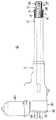
図1に示されているように、本実施の形態に係るリニアアクチュエータは医療・介護用ベッド(以下、ベッドという。)の背部の寝床を起伏させるためのものとして構成されている。
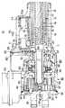
すなわち、図2および図3に示されているように、リニアアクチュエータ7はハウジング11と、ハウジング11に対して進退する移動筒12とからなるアクチュエータ本体10を備えており、リニアアクチュエータ7の固定端側であるハウジング11がベッド1のフレーム2に枢軸3によって回転自在に枢支され、リニアアクチュエータ7の自由端側である移動筒12の先端が背部の寝床(以下、寝床という。)4を起伏させるためのリンク5に枢軸6によって回転自在に連結されている。
図1(a)に示されているように、リニアアクチュエータ7の移動筒12が短縮した状態で、寝床4は水平に倒伏されており、リニアアクチュエータ7の移動筒12が伸長すると、寝床4は図1(b)に示されているように起立されるようになっている。As shown in FIG. 1, the linear actuator according to the present embodiment is configured to raise and lower the bed on the back of a medical / care bed (hereinafter referred to as a bed).
That is, as shown in FIGS. 2 and 3, the
As shown in FIG. 1A, the
図3に示されているように、リニアアクチュエータ7(アクチュエータ本体10)のハウジング11は樹脂が使用されて略円筒形状に形成されており、ハウジング11の一端部(以下、先端部とする。)には、支持筒13の一端部が嵌入されて支持されている。支持筒13は外径がハウジング11の内径と等しい断面円筒形の丸パイプ形状に形成されている。
支持筒13の内周面には雌ねじ部材を回り止めするための回り止め部14が一対、略全長にわたってそれぞれ敷設されており、両回り止め部14、14は軸方向に一定幅一定高さに延在する細長いキー形状にそれぞれ形成されている。
図2に示されているように、支持筒13の先端開口部には外周に鍔部を有する円筒形状に形成されたプラグ部15が嵌入されている。As shown in FIG. 3, the housing 11 of the linear actuator 7 (actuator body 10) is formed in a substantially cylindrical shape using resin, and is one end portion (hereinafter referred to as a tip portion) of the housing 11. One end portion of the
A pair of
As shown in FIG. 2, a plug portion 15 formed in a cylindrical shape having a flange portion on the outer periphery is fitted into the distal end opening portion of the
支持筒13の筒心上には送りねじ軸としてのシャフト16が軸架されている。シャフト16の支持筒13に対応する領域の外周には送り用の雄ねじ部17が形成されており、雄ねじ部17には雌ねじ部18が螺合されたナット19が進退自在に装着されている。
ナット19の基端部の外周部には、キー溝形状に形成された回り止め部20が一対それぞれ形成されており、両回り止め部20、20は支持筒13の内周面の一対の回り止め部14、14に軸方向に摺動自在にそれぞれ嵌合されている。したがって、ナット19は支持筒13に回り止め部14、20によって回り止めされた状態で、軸方向に摺動するようになっている。A
A pair of
ナット19の先端部外周には移動筒12の基端部が嵌入されており、移動筒12はナット19に固定部23によって固定されている。移動筒12は支持筒13よりも長い丸パイプ形状に形成されている。 The base end portion of the
図2に示されているように、移動筒12の先端部は、支持筒13に嵌着されたプラグ部15から先方に突き出されており、移動筒12の中間部はプラグ部15によって摺動自在に支承されている。
移動筒12の先端部には移動筒12をベッド1のリンク5に連結するための連結具25の基端部26が嵌入されており、連結具25は移動筒12の先端開口部に固定されている。連結具25の先端部には取付孔27が開設されており、枢軸6が取付孔27に挿入されることにより、移動筒12がリンク5に連結されるようになっている。As shown in FIG. 2, the distal end portion of the
A
図3に示されているように、ハウジング11の基端面にはサブハウジング30が当接されている。サブハウジング30は外径がハウジング11の外径と同一でハウジング11と反対側の端面が開口した筒形状に形成されており、その開口部にはハウジング11をベッド1のフレーム2に連結するための連結具32の閉塞部33が被せられている。サブハウジング30および連結具32の閉塞部33はハウジング11に、複数本のビスによって一緒に締結されている。
連結具32の外側端面にはブラケット34が突設されており、ブラケット34には取付孔35が開設されている。枢軸3が取付孔35に挿入されることにより、リニアアクチュエータ10の基端部がフレーム2に連結されるようになっている。As shown in FIG. 3, the
A bracket 34 protrudes from the outer end surface of the
図3に示されているように、サブハウジング30における開口部31と直角の位置にはモータ装着部36が開設されており、モータ装着部36にはモータ40が、回転軸がサブハウジング30の中心線方向と直交するように配されて装着されている。
モータ40の回転軸の一端部はサブハウジング30の内部に挿入されており、回転軸の中間部はモータ装着部36に回転自在に支承されている。As shown in FIG. 3, a
One end portion of the rotation shaft of the
回転軸のサブハウジング30内の挿入部分の外周には、互いに反対向きの捩れを有する一対のウオーム42、43がそれぞれ一体的に形成されている。サブハウジング30の一対のウオーム42、43にそれぞれ対向する位置であって回転軸の互いに反対側の位置には、一対の支持軸44、45がサブハウジング30の中心線方向と平行にそれぞれ植設されている。
一対の支持軸44、45には一対のウオームホイール46、47がそれぞれ嵌合されて回転自在に支承されており、一対のウオームホイール46、47は一対のウオーム42、43にそれぞれ噛合されている。一対のウオームホイール46、47には一対の中間ギヤ48、49が軸芯合わせされて一体的にそれぞれ連設されており、一対の中間ギヤ48、49は同一の駆動ギヤ50にそれぞれ噛合されている。A pair of worms 42 and 43 having twists opposite to each other are integrally formed on the outer periphery of the insertion portion in the
A pair of
図3に示されているように、駆動ギヤ50はサブハウジング30からハウジング11にわたって軸架されたサブシャフト52に滑りキー結合されることにより、軸方向に摺動自在で一体的に回転するように結合されている。
このように駆動ギヤ50をサブシャフト52に軸方向に摺動自在で一体的に回転するように結合することにより、サブシャフト52に加わる軸方向(スラスト方向)の荷重(力)が駆動ギヤ50に伝達されるのを防止することができる。
但し、駆動ギヤ50はサブシャフト52に一体成形してもよい。As shown in FIG. 3, the drive gear 50 is slidably coupled to a sub-shaft 52 that extends from the sub-housing 30 to the housing 11 so as to be slidable in the axial direction and rotate integrally. Is bound to.
In this way, the drive gear 50 is coupled to the
However, the drive gear 50 may be integrally formed with the
図3に示されているように、ハウジング11のサブハウジング30に隣接する部分には軸受設置部53が形成されており、軸受設置部53には深溝玉軸受54が設置されている。深溝玉軸受54のインナレースはシャフト16の基端部の外周にカラー55を介して嵌合されており、シャフト16の基端部は深溝玉軸受54によって回転自在に支承されている。
深溝玉軸受54はシャフト16のラジアル荷重だけでなくシャフト16のスラスト荷重も支承し得るようにサイズが大きめに設定されており、軸受設置部53は深溝玉軸受54のアウタレースの外周面を摺動させる構造に構成されている。
このようにシャフト16を回転自在に支承するラジアル転がり軸受をサイズが大きめの深溝玉軸受54によって構成し、外周面で摺動し得るように設定することにより、シャフト16のスラスト荷重を支承するスラスト軸受を省略することができる。As shown in FIG. 3, a
The deep
Thus, the radial rolling bearing that rotatably supports the
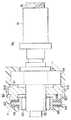
図3および図4に示されているように、ハウジング11の軸受設置部53に隣接する部位には、ブレーキ機構設置部56が軸受設置部53と連続して形成されており、ブレーキ機構設置部56には、シャフト16の一端側に配されてシャフト16の一方向の回転時にカラー55すなわちシャフト16とハウジング11との間で制動力を発揮するブレーキ機構60が設置されている。 As shown in FIGS. 3 and 4, a brake
ブレーキ機構60は可動ブロック61およびブレーキプレート62を備えている。
可動ブロック61は深溝玉軸受54とハウジング11との間に配置されており、深溝玉軸受54側端が深溝玉軸受54のアウタレースに当接可能に設けられているとともに、その外周の4箇所には軸方向に長いガイド突起61Aが周方向に等間隔に設けられている。また、ハウジング11には、回転方向に一体回転可能かつ軸方向に移動可能にガイド突起61Aと係合する4条のガイド溝11Aが設けられ、これにより、可動ブロック61はカラー55すなわちシャフト16と一体回転不可能かつハウジング11に対して回転方向に一体回転可能かつ軸方向に移動可能に設けられている。
ブレーキプレート62は可動ブロック61の深溝玉軸受54側と反対側端とハウジング11との間に設けられており、内部にはワンウエイ機構としてのワンウエイクラッチ63が設けられている。ワンウエイクラッチ63はシャフト16の一方向の回転時にシャフト16と一体回転可能に構成されている。
ブレーキプレート62は円形リング形状に形成されたベースプレート64を備えており、ベースプレート64はワンウエイクラッチ63の外周に突設されている。ベースプレート64の可動ブロック61との対向面には、円形リング形状に形成された第一摩擦板65が一体的に設けられており、第一摩擦板65は可動ブロック61との間において摩擦力を発揮するように構成されている。ベースプレート64のハウジング11との対向面には円形リング形状に形成された第二摩擦板66が一体的に設けられており、第二摩擦板66はハウジング11との間において摩擦力を発揮するように構成されている。
なお、可動ブロック61のブレーキプレート62との対向面すなわち可動ブロック61と第一摩擦板65との対向面と、ハウジング11のブレーキプレート62との対向面すなわちハウジング11と第二摩擦板66との対向面には、所定の摩擦力を発揮するように面加工された受面61B、11Bとされている。The
The
The
The
Note that the surface of the
図3に示されているように、ハウジング11のシャフト16基端部脇には位置検出機構設置部70が構成されており、位置検出機構設置部70内には位置検出機構71が設置されている。
位置検出機構71はハウジング11の内側に固定された一対のブラケット72A、72Aとブラケット72A、72A間に固定された基板72Bとを備えており、基板72Bは位置検出機構設置部70内にシャフト16と平行に固定されている。ブラケット72A、72Aの間には位置検出シャフト73が、シャフト16と平行に軸架された状態でその両端が回転自在に支持されている。位置検出シャフト73は全長がシャフト16よりも短く、雄ねじ部74が略全長にわたって形成されており、雄ねじ部74にはストライカ75が進退自在に螺合されている。すなわち、ストライカ75はハウジング11またはブラケット72に回り止めされた状態で摺動自在に案内されるようになっている。
なお、本実施の形態においては、雄ねじ部74のピッチはシャフト16の雄ネジ部17のピッチと同じに設定されている。
基板72Bのブラケット72A、72A寄りのそれぞれの位置の両端部には一対の位置検出スイッチ76、77が、位置検出シャフト73に対向するように固定されており、図5に示されているように、一対の位置検出スイッチ76、77はストライカ75の移動両端部の位置をそれぞれ検出するようになっている。すなわち、位置検出シャフト73の基端側端部に配置された位置検出スイッチ(以下、下限スイッチという)76は、位置検出シャフト73の基端側端部に位置するストライカ75を検出し、位置検出シャフト73の先端側端部に配置された位置検出スイッチ(以下、上限スイッチという)77は、位置検出シャフト73の先端側端部に位置するストライカ75を検出するようになっている。
なお、図示しないが、基板72B上にはストライカ75の位置検出に必要なその他の電気素子が配されている。As shown in FIG. 3, a position detection mechanism installation portion 70 is configured beside the base end portion of the
The
In the present embodiment, the pitch of the
A pair of position detection switches 76 and 77 are fixed to both ends of the
Although not shown, other electric elements necessary for detecting the position of the
図3および図5に示されているように、位置検出機構71は歯車減速装置80を備えており、歯車減速装置80の原動ギヤ81はシャフト16の基端部に固定されている。原動ギヤ81には原動ギヤ81よりも大径すなわち歯数の大きい従動ギヤ82が噛合されており、従動ギヤ82はハウジング11に回転自在に支持されている。従動ギヤ82には第二段原動ギヤ83が一体回転するように固定されており、第二段原動ギヤ83には第二段原動ギヤ83よりも大径すなわち歯数の大きい第二段従動ギヤ84が噛合されている。第二段従動ギヤ84は位置検出シャフト73の基端側端部に固定されている。
シャフト16の回転は、原動ギヤ81→従動ギヤ82→第二段原動ギヤ83→第二段従動ギヤ84を経由して減速され、位置検出シャフト73に伝達される。As shown in FIGS. 3 and 5, the
The rotation of the
次に、作用および効果を説明する。 Next, functions and effects will be described.
予め、リニアアクチュエータ7(アクチュエータ本体10)はベッド1に、図1に示されているように組み付けられる。すなわち、枢軸3がベッド1のフレーム2に挿通されてリニアアクチュエータ7の連結具32に挿通されることにより、リニアアクチュエータ7枢軸3によってベッド1のフレーム2に回転自在に枢支され、寝床4側の枢軸6がリニアアクチュエータ7の移動筒12側の連結具25に挿通されることにより、リニアアクチュエータ7は寝床4に枢軸6によって回転自在に連結される。 The linear actuator 7 (actuator body 10) is assembled to the bed 1 in advance as shown in FIG. That is, the
リニアアクチュエータ7がベッド1に組み付けられた後に、操作者が寝床4を起立させるべく正回転側の操作ボタンを押すことにより、図1(a)の状態から、モータ40が正方向に回転運転されると、回転軸の駆動力が一対のウオーム42、43、一対のウオームホイール46、47、一対の中間ギヤ48、49および駆動ギヤ50を介してサブシャフト52に伝達される。サブシャフト52の正回転はカラー55を介してシャフト16に伝達される。
このシャフト16の正回転時にはワンウエイ機構が働かず、ワンウエイクラッチ63とシャフト16との連結が解除されるために、ブレーキ機構60の制動力は起こらない。After the
During the forward rotation of the
シャフト16がモータ40によって正回転されると、ナット19は支持筒13に沿って前進される状態になるために、ナット19に連結された移動筒12は支持筒13から押し出されて行く。この際、ナット19は支持筒13の回り止め部14に沿って摺動する。
なお、回り止め機構はリニアアクチュエータ7がベッド1に取り付けられていない時に移動筒12が回ってしまい、位置検出機構71と移動筒12との位置関係に狂いが出てしまうのを防止するためのものであり、リニアアクチュエータ7がベッド1に取り付いてしまうと、移動筒12がベッド1に固定された状態になるので、不要になる。When the
The anti-rotation mechanism is for preventing the moving
移動筒12の前進によって移動筒12の連結具25に連結されたベッド1の寝床4が、図1(b)に示されているように起立されて行く。 The
他方、シャフト16の正回転は、原動ギヤ81→従動ギヤ82→第二段原動ギヤ83→第二段従動ギヤ84を経由して、位置検出シャフト73に減速されて伝達される。位置検出シャフト73の正回転に伴って、ストライカ75は先端側に向かって前進する。
ストライカ75が上限位置まで前進すると、上限スイッチ77がストライカ75を検出するので、モータ40は自動的に停止される。On the other hand, the forward rotation of the
When the
モータ40の運転が停止されると、ベッド1の寝床4の荷重(患者の体重等)がナット19へ、ナット19を後退させる方向の力として移動筒12を介して作用する状態になるために、シャフト16には移動筒12すなわち負荷側から逆回転させようとする負荷側逆回転作用力が、ナット19の雌ねじ部18およびシャフト16の送り用雄ねじ部17の作用によって加わる。
この負荷側逆回転作用力はブレーキプレート62とシャフト16すなわちカラー55とを連結させるように作用するために、ワンウエイクラッチ63を内蔵したブレーキプレート62の第一摩擦板65および第二摩擦板66によって制動面が形成され、シャフト16は逆回転を阻止される。したがって、リニアアクチュエータ7は寝床4の荷重を持ち上げたままの状態で支持することができる。When the operation of the
This load side reverse rotation force acts to connect the
その後に、操作者が寝床4を倒伏させるべく逆回転側の操作ボタンを押すことにより、モータ40が逆方向に回転運転されると、回転軸の逆回転駆動力は一対のウオーム42、43、一対のウオームホイール46、47、一対の中間ギヤ48、49および駆動ギヤ50を介してサブシャフト52に伝達される。サブシャフト52の逆回転はカラー55を介してシャフト16に伝達される。
シャフト16がモータ40によって逆回転されると、ナット19は支持筒13に沿って後退される状態になるために、ナット19に連結された移動筒12は支持筒13に引き込まれて行く。移動筒12の後退によって移動筒12の連結具25に連結されたベッド1の寝床4が倒されて行く。
この際にはシャフト16が逆回転するために、ワンウエイクラッチ63は連結した状態になるが、ブレーキプレート62の第一摩擦板65および第二摩擦板66の制動力は、シャフト16の逆回転力よりも僅かに大きく設定されているため、モータ40はこの制動力と逆回転力との差の分だけ駆動すればよく、クラッチケース58はカラー55に対してワンウエイ機構で連結されていても、モータ40は小さな駆動力でシャフト16のハウジング11に対する逆回転を許容する。
つまり、シャフト16がハウジング11に対して逆回転することにより、ナット19を支持筒13に沿って後退させるので、ナット19に連結された移動筒12を支持筒13に引き込み、移動筒12の連結具25に連結されたベッド1の寝床4を倒して行く。After that, when the operator presses the operation button on the reverse rotation side to lie down the
When the
At this time, since the
That is, when the
他方、シャフト16の逆回転は、原動ギヤ81→従動ギヤ82→第二段原動ギヤ83→第二段従動ギヤ84を経由して、位置検出シャフト73に減速されて伝達される。位置検出シャフト73の逆回転に伴って、ストライカ75は基端側に向かって後退する。
ストライカ75が下限位置まで前進すると、下限スイッチ76がストライカ75を検出するので、モータ40は自動的に停止される。On the other hand, the reverse rotation of the
When the
モータ40の運転が停止されると、寝床4の荷重(患者の体重等)はベッド1のフレーム2によって機械的に支持されることにより、移動筒12にはナット19に後退させる方向の力が作用する状態にならないために、負荷側逆回転作用力がシャフト16に作用することはない。
但し、寝床4が倒伏した状態で、負荷側逆回転力がシャフト16に常に加わったとしても、シャフト16の逆回転は前述した作用によって防止されることになる。When the operation of the
However, even if the load-side reverse rotational force is constantly applied to the
本実施の形態によれば、次のような効果を得ることができる。 According to the present embodiment, the following effects can be obtained.
1) ブレーキプレートの両端面をブレーキ面として使用することにより、2倍のブレーキ力を創出することができるので、従来のブレーキ面と同一直径の場合にはブレーキ力を2倍に増強することができ、従来のブレーキ力と同一のブレーキ力の場合には直径を半分に抑制することができる。1) By using both end faces of the brake plate as the brake surface, it is possible to create twice the braking force, so if the diameter is the same as that of the conventional brake surface, the braking force can be doubled. In the case of the same braking force as the conventional braking force, the diameter can be reduced to half.
2) ワンウエイクラッチをブレーキプレートとシャフトとの間に設けることにより、直径をより一層小さく抑制することができる。2) By providing the one-way clutch between the brake plate and the shaft, the diameter can be further reduced.
3) ベースプレートの可動ブロックとの対向面に第一摩擦板を設け、ベースプレートのハウジングとの対向面には第二摩擦板を設けることにより、所望の摩擦力を任意かつ精密に設計することができる。3) By providing the first friction plate on the surface of the base plate facing the movable block and providing the second friction plate on the surface of the base plate facing the housing, the desired friction force can be designed arbitrarily and precisely. .
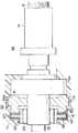
図6は本発明の第二実施形態であるリニアアクチュエータのブレーキ機構を示す模式図である。 FIG. 6 is a schematic diagram showing a brake mechanism of a linear actuator according to the second embodiment of the present invention.
本実施形態が前記実施形態と異なる点は、ブレーキプレート62外周とハウジング11の内周との間には、所定の摩擦力を発揮する摩擦部材67が設けられるとともに、ハウジング11のブレーキプレート62との対向面すなわちハウジング11と摩擦部材67との対向面には、所定の摩擦力を発揮するように面加工された受面11Cが設けられている点である。 The present embodiment is different from the above-described embodiment in that a friction member 67 that exhibits a predetermined friction force is provided between the outer periphery of the
本実施形態によれば、ブレーキプレート62外周とハウジング11の内周との間の摩擦力を摩擦部材67によって増強することができる。 According to this embodiment, the friction force between the outer periphery of the
なお、本発明は前記実施の形態に限定されるものではなく、その要旨を逸脱しない範囲で種々に変更が可能であることはいうまでもない。 Needless to say, the present invention is not limited to the above-described embodiment, and various modifications can be made without departing from the scope of the invention.
前記実施形態では、ベッドの背部の寝床を起伏させる場合について説明したが、本発明に係るリニアアクチュエータは、ベッドの床面を上下させるように構成してもよい。 In the above embodiment, the case where the bed on the back of the bed is raised and lowered has been described. However, the linear actuator according to the present invention may be configured to move the floor of the bed up and down.
また、前記実施形態においては、寝床の荷重(患者の体重等)をベッドのフレームによって機械的に支持する構造に適用したものを説明したが、本発明に係るブレーキ機構は、寝床の荷重をリニアアクチュエータ側で支持する構造に適用することもできる。 Further, in the above embodiment, the description has been given of the case where the bed load (such as the patient's weight) is mechanically supported by the bed frame. However, the brake mechanism according to the present invention linearizes the bed load. The present invention can also be applied to a structure that is supported on the actuator side.
また、前記実施の形態においては、リニアアクチュエータが医療・介護用ベッドに使用される場合について説明したが、本発明に係るアクチュエータはこれに限らず、自動車電装品等の用途にも適用することができる。 Moreover, in the said embodiment, although the case where a linear actuator was used for the bed for medical care and nursing care was demonstrated, the actuator which concerns on this invention is applicable not only to this but to uses, such as a vehicle electrical component. it can.
さらに、前記実施の形態においては、可動ブロックの第一摩擦板との対向面と、ハウジングの第二摩擦板との対向面と、ハウジングの摩擦部材との対向面とに、所定の摩擦力を発揮する受面を設けたものを示したが、これに限らず、各対向面として各部材の成形時の面をそのまま使うようにしてもよく、また、これらの受面を別部材にて構成して一体化するようにしてもよい。 Further, in the above-described embodiment, a predetermined friction force is applied to the surface facing the first friction plate of the movable block, the surface facing the second friction plate of the housing, and the surface facing the friction member of the housing. Although the one provided with the receiving surface to be demonstrated is shown, the surface at the time of molding of each member may be used as it is as each facing surface as it is, and these receiving surfaces are constituted by separate members. And may be integrated.
さらに、前記実施の形態においては、可動ブロックの外周に4条のガイド突起を設け、ハウジングの内壁のガイド溝と摺動自在に係合するようにした例を示したが、ガイド突起は4条に限らず、また、ブレーキ面の有効面積を確保するために、可動ブロックとハウジングとはスプラインやセレーションによる係合としてもよい。 Furthermore, in the above-described embodiment, an example in which four guide protrusions are provided on the outer periphery of the movable block and slidably engaged with the guide groove on the inner wall of the housing has been shown. In addition, the movable block and the housing may be engaged by splines or serrations in order to secure an effective area of the brake surface.
1…ベッド(医療・介護用ベッド)、2…フレーム、3…枢軸、4…寝床、5…リンク、6…枢軸、7…リニアアクチュエータ、
10…アクチュエータ本体、11…ハウジング、11A…ガイド溝、11B…受面、11C…受面、12…移動筒、13…支持筒、14…回り止め部、15…プラグ部、16…シャフト(送りねじ軸)、17…雄ねじ部、18…雌ねじ部、19…ナット、20…回り止め部、23…固定部、25…連結具、26…基端部、27…取付孔、
30…サブハウジング、31…開口部、32…連結具、33…閉塞部、34…ブラケット、35…取付孔、36…モータ装着部、40…モータ、
42、43…ウオーム、44、45…支持軸、46、47…ウオームホイール、48、49…中間ギヤ、50…駆動ギヤ、
52…サブシャフト、53…軸受設置部、54…深溝玉軸受、55…カラー、
60…ブレーキ機構、61…可動ブロック、61A…ガイド突起、61B…受面、62…ブレーキプレート、63…ワンウエイクラッチ、64…ベースプレート、65…第一摩擦板、66…第二摩擦板、67…摩擦部材、
70…位置検出機構設置部、71…位置検出機構、72A…ブラケット、72B…基板、73…位置検出シャフト、74…雄ねじ部、75…ストライカ、76、77…位置検出スイッチ、
80…歯車減速装置、81…原動ギヤ、82…従動ギヤ、83…第二段原動ギヤ、84…第二段従動ギヤ、85…第三段原動ギヤ、86…第三段従動ギヤ、
90…ポテンショセンサ、91…センサ軸、92…ポテンショメータ。DESCRIPTION OF SYMBOLS 1 ... Bed (medical / care bed), 2 ... Frame, 3 ... Axis, 4 ... Sleeping bed, 5 ... Link, 6 ... Axis, 7 ... Linear actuator,
DESCRIPTION OF
DESCRIPTION OF
42, 43 ... Worm, 44, 45 ... Support shaft, 46, 47 ... Worm wheel, 48, 49 ... Intermediate gear, 50 ... Drive gear,
52 ... Sub shaft, 53 ... Bearing installation part, 54 ... Deep groove ball bearing, 55 ... Color,
60 ...
DESCRIPTION OF SYMBOLS 70 ... Position detection mechanism installation part, 71 ... Position detection mechanism, 72A ... Bracket, 72B ... Board | substrate, 73 ... Position detection shaft, 74 ... Male screw part, 75 ... Striker, 76, 77 ... Position detection switch,
80: gear reduction device, 81: driving gear, 82: driven gear, 83: second stage driving gear, 84: second stage driving gear, 85: third stage driving gear, 86: third stage driving gear,
90 ... potentiometer sensor, 91 ... sensor shaft, 92 ... potentiometer.
Claims (2)
Translated fromJapanese前記ブレーキ機構は、
前記軸受と前記ハウジングとの間で一端側が前記軸受に当接可能に設けられるとともに、前記送りねじ軸と一体回転不可能かつ前記ハウジングに対して回転方向に一体回転可能かつ軸方向に移動可能に設けられた可動ブロックと、
該可動ブロックの他端側と前記ハウジングとの間に設けられるとともに、内部に前記送りねじ軸の一方向の回転時に前記送りねじ軸と一体回転可能に設けられたワンウエイクラッチが設けられるとともに、前記可動ブロックとの接触面と、前記ハウジングとの接触面とにおいて摩擦力を発揮するブレーキ面を備えたブレーキプレートと、
から構成されており、
前記ブレーキプレートと前記ハウジングとの間には、所定の摩擦力を発揮する摩擦部材が設けられている、
ことを特徴とするリニアアクチュエータ。A motor coupled to the housing; a feed screw shaft rotatably supported by a bearing on the housing; and an output shaft of the motor and the feed screw shaft interposed therebetween to rotate the output shaft of the motor. A speed reduction device that decelerates and transmits it to the feed screw shaft, a nut that is screwed to the feed screw shaft so as to advance and retreat, a moving cylinder that is connected to the nut so as to move integrally, and the feed screw shaft A brake mechanism that is disposed on one end of the feed screw shaft and exerts a braking force between the feed screw shaft and the housing when rotating in one direction of the feed screw shaft,
The brake mechanism is
One end side is contactable to said bearings between said bearing housing, movablyintegrally rotatable and axiallyin the direction of rotation relative to said feed screw shaft integrally rotatingimpossible and the housing A movable block provided;
A one-way clutch provided between the other end side of the movable block and the housing, and provided therein so as to be integrally rotatable with the feed screw shaft when rotating in one direction of the feed screw shaft, A brake plate having a brake surface that exerts a frictional force on the contact surface with the movable block and the contact surface with the housing;
Consists of
Between the brake plate and the housing, a friction member that exhibits a predetermined friction force is provided,
A linear actuator characterized by that.
リング形状に形成されたベースプレートと、
該ベースプレートの前記可動ブロックとの当接面と、前記ハウジングとの当接面とに一体的にリング形状に設けられ、所定の摩擦力を発揮する摩擦板と、
から構成されることを特徴とする請求項1に記載のリニアアクチュエータ。The brake plate is
A base plate formed in a ring shape;
A friction plate that is provided integrally with a contact surface of the base plate with the movable block and a contact surface with the housing and that exhibits a predetermined friction force;
The linear actuator according to claim 1, comprising:
Priority Applications (1)
| Application Number | Priority Date | Filing Date | Title |
|---|---|---|---|
| JP2008233163AJP5123121B2 (en) | 2008-09-11 | 2008-09-11 | Linear actuator |
Applications Claiming Priority (1)
| Application Number | Priority Date | Filing Date | Title |
|---|---|---|---|
| JP2008233163AJP5123121B2 (en) | 2008-09-11 | 2008-09-11 | Linear actuator |
Publications (2)
| Publication Number | Publication Date |
|---|---|
| JP2010065772A JP2010065772A (en) | 2010-03-25 |
| JP5123121B2true JP5123121B2 (en) | 2013-01-16 |
Family
ID=42191518
Family Applications (1)
| Application Number | Title | Priority Date | Filing Date |
|---|---|---|---|
| JP2008233163AExpired - Fee RelatedJP5123121B2 (en) | 2008-09-11 | 2008-09-11 | Linear actuator |
Country Status (1)
| Country | Link |
|---|---|
| JP (1) | JP5123121B2 (en) |
Families Citing this family (2)
| Publication number | Priority date | Publication date | Assignee | Title |
|---|---|---|---|---|
| JP6021449B2 (en)* | 2012-06-05 | 2016-11-09 | Thk株式会社 | Actuator |
| WO2013183278A1 (en)* | 2012-06-05 | 2013-12-12 | Thk株式会社 | Actuator |
Family Cites Families (2)
| Publication number | Priority date | Publication date | Assignee | Title |
|---|---|---|---|---|
| JPS58167335U (en)* | 1982-04-30 | 1983-11-08 | 三菱電機株式会社 | electromagnetic brake |
| JPH09100892A (en)* | 1995-10-03 | 1997-04-15 | Mitsuba Corp | Actuator |
- 2008
- 2008-09-11JPJP2008233163Apatent/JP5123121B2/ennot_activeExpired - Fee Related
Also Published As
| Publication number | Publication date |
|---|---|
| JP2010065772A (en) | 2010-03-25 |
Similar Documents
| Publication | Publication Date | Title |
|---|---|---|
| JP5225599B2 (en) | Linear actuator for bed | |
| JP5097551B2 (en) | Linear actuator | |
| JP4633355B2 (en) | Linear actuator | |
| EP2232101B1 (en) | Linear actuator | |
| US20050160846A1 (en) | Linear actuator | |
| US9797491B2 (en) | Electric actuator assembly | |
| US20140202271A1 (en) | An electromotive linear drive | |
| JP5185278B2 (en) | Linear actuator | |
| JP2007187279A (en) | Linear actuator | |
| US10316945B2 (en) | Linear actuator device | |
| JP5123121B2 (en) | Linear actuator | |
| JP5049932B2 (en) | Linear actuator | |
| JP2010263670A (en) | Linear actuator | |
| JP2014029190A (en) | Linear actuator | |
| JP2010065771A (en) | Linear actuator | |
| JP4585761B2 (en) | Linear actuator | |
| JPH0842657A (en) | Actuator | |
| JP4578801B2 (en) | Linear actuator | |
| JP4981627B2 (en) | Linear actuator | |
| JP2007154954A (en) | Linear actuator | |
| JP4480998B2 (en) | Linear actuator | |
| JP2014101979A (en) | Linear actuator | |
| CN104214296A (en) | Electric cylinder with position detection mechanism | |
| JP2006105186A (en) | Linear actuator | |
| JP2009041698A (en) | Linear actuator |
Legal Events
| Date | Code | Title | Description |
|---|---|---|---|
| A621 | Written request for application examination | Free format text:JAPANESE INTERMEDIATE CODE: A621 Effective date:20110407 | |
| A977 | Report on retrieval | Free format text:JAPANESE INTERMEDIATE CODE: A971007 Effective date:20120326 | |
| A131 | Notification of reasons for refusal | Free format text:JAPANESE INTERMEDIATE CODE: A131 Effective date:20120403 | |
| A521 | Request for written amendment filed | Free format text:JAPANESE INTERMEDIATE CODE: A523 Effective date:20120531 | |
| A131 | Notification of reasons for refusal | Free format text:JAPANESE INTERMEDIATE CODE: A131 Effective date:20120710 | |
| A521 | Request for written amendment filed | Free format text:JAPANESE INTERMEDIATE CODE: A523 Effective date:20120828 | |
| TRDD | Decision of grant or rejection written | ||
| A01 | Written decision to grant a patent or to grant a registration (utility model) | Free format text:JAPANESE INTERMEDIATE CODE: A01 Effective date:20121023 | |
| A01 | Written decision to grant a patent or to grant a registration (utility model) | Free format text:JAPANESE INTERMEDIATE CODE: A01 | |
| A61 | First payment of annual fees (during grant procedure) | Free format text:JAPANESE INTERMEDIATE CODE: A61 Effective date:20121025 | |
| FPAY | Renewal fee payment (event date is renewal date of database) | Free format text:PAYMENT UNTIL: 20151102 Year of fee payment:3 | |
| R150 | Certificate of patent or registration of utility model | Free format text:JAPANESE INTERMEDIATE CODE: R150 Ref document number:5123121 Country of ref document:JP Free format text:JAPANESE INTERMEDIATE CODE: R150 | |
| LAPS | Cancellation because of no payment of annual fees |