JP5122550B2 - PTC heater control method and air conditioner - Google Patents
PTC heater control method and air conditionerDownload PDFInfo
- Publication number
- JP5122550B2 JP5122550B2JP2009268882AJP2009268882AJP5122550B2JP 5122550 B2JP5122550 B2JP 5122550B2JP 2009268882 AJP2009268882 AJP 2009268882AJP 2009268882 AJP2009268882 AJP 2009268882AJP 5122550 B2JP5122550 B2JP 5122550B2
- Authority
- JP
- Japan
- Prior art keywords
- ptc heater
- current value
- duty
- duty ratio
- heater
- Prior art date
- Legal status (The legal status is an assumption and is not a legal conclusion. Google has not performed a legal analysis and makes no representation as to the accuracy of the status listed.)
- Expired - Fee Related
Links
Images


Classifications
- F—MECHANICAL ENGINEERING; LIGHTING; HEATING; WEAPONS; BLASTING
- F24—HEATING; RANGES; VENTILATING
- F24F—AIR-CONDITIONING; AIR-HUMIDIFICATION; VENTILATION; USE OF AIR CURRENTS FOR SCREENING
- F24F1/00—Room units for air-conditioning, e.g. separate or self-contained units or units receiving primary air from a central station
- F24F1/02—Self-contained room units for air-conditioning, i.e. with all apparatus for treatment installed in a common casing
- F24F1/022—Self-contained room units for air-conditioning, i.e. with all apparatus for treatment installed in a common casing comprising a compressor cycle
- F—MECHANICAL ENGINEERING; LIGHTING; HEATING; WEAPONS; BLASTING
- F24—HEATING; RANGES; VENTILATING
- F24F—AIR-CONDITIONING; AIR-HUMIDIFICATION; VENTILATION; USE OF AIR CURRENTS FOR SCREENING
- F24F11/00—Control or safety arrangements
- F24F11/30—Control or safety arrangements for purposes related to the operation of the system, e.g. for safety or monitoring
- F—MECHANICAL ENGINEERING; LIGHTING; HEATING; WEAPONS; BLASTING
- F24—HEATING; RANGES; VENTILATING
- F24F—AIR-CONDITIONING; AIR-HUMIDIFICATION; VENTILATION; USE OF AIR CURRENTS FOR SCREENING
- F24F11/00—Control or safety arrangements
- F24F11/62—Control or safety arrangements characterised by the type of control or by internal processing, e.g. using fuzzy logic, adaptive control or estimation of values
- F24F11/63—Electronic processing
- F—MECHANICAL ENGINEERING; LIGHTING; HEATING; WEAPONS; BLASTING
- F24—HEATING; RANGES; VENTILATING
- F24F—AIR-CONDITIONING; AIR-HUMIDIFICATION; VENTILATION; USE OF AIR CURRENTS FOR SCREENING
- F24F11/00—Control or safety arrangements
- F24F11/70—Control systems characterised by their outputs; Constructional details thereof
- F24F11/72—Control systems characterised by their outputs; Constructional details thereof for controlling the supply of treated air, e.g. its pressure
- F24F11/74—Control systems characterised by their outputs; Constructional details thereof for controlling the supply of treated air, e.g. its pressure for controlling air flow rate or air velocity
- F24F11/77—Control systems characterised by their outputs; Constructional details thereof for controlling the supply of treated air, e.g. its pressure for controlling air flow rate or air velocity by controlling the speed of ventilators
- F—MECHANICAL ENGINEERING; LIGHTING; HEATING; WEAPONS; BLASTING
- F24—HEATING; RANGES; VENTILATING
- F24F—AIR-CONDITIONING; AIR-HUMIDIFICATION; VENTILATION; USE OF AIR CURRENTS FOR SCREENING
- F24F11/00—Control or safety arrangements
- F24F11/70—Control systems characterised by their outputs; Constructional details thereof
- F24F11/80—Control systems characterised by their outputs; Constructional details thereof for controlling the temperature of the supplied air
- F—MECHANICAL ENGINEERING; LIGHTING; HEATING; WEAPONS; BLASTING
- F24—HEATING; RANGES; VENTILATING
- F24F—AIR-CONDITIONING; AIR-HUMIDIFICATION; VENTILATION; USE OF AIR CURRENTS FOR SCREENING
- F24F11/00—Control or safety arrangements
- F24F11/88—Electrical aspects, e.g. circuits
- H—ELECTRICITY
- H05—ELECTRIC TECHNIQUES NOT OTHERWISE PROVIDED FOR
- H05B—ELECTRIC HEATING; ELECTRIC LIGHT SOURCES NOT OTHERWISE PROVIDED FOR; CIRCUIT ARRANGEMENTS FOR ELECTRIC LIGHT SOURCES, IN GENERAL
- H05B1/00—Details of electric heating devices
- H05B1/02—Automatic switching arrangements specially adapted to apparatus ; Control of heating devices
- H05B1/0227—Applications
- H05B1/0252—Domestic applications
- H05B1/0275—Heating of spaces, e.g. rooms, wardrobes
- H05B1/028—Airconditioning
- F—MECHANICAL ENGINEERING; LIGHTING; HEATING; WEAPONS; BLASTING
- F24—HEATING; RANGES; VENTILATING
- F24F—AIR-CONDITIONING; AIR-HUMIDIFICATION; VENTILATION; USE OF AIR CURRENTS FOR SCREENING
- F24F11/00—Control or safety arrangements
- F24F11/50—Control or safety arrangements characterised by user interfaces or communication
- F24F11/56—Remote control
- F—MECHANICAL ENGINEERING; LIGHTING; HEATING; WEAPONS; BLASTING
- F24—HEATING; RANGES; VENTILATING
- F24F—AIR-CONDITIONING; AIR-HUMIDIFICATION; VENTILATION; USE OF AIR CURRENTS FOR SCREENING
- F24F2140/00—Control inputs relating to system states
- F—MECHANICAL ENGINEERING; LIGHTING; HEATING; WEAPONS; BLASTING
- F24—HEATING; RANGES; VENTILATING
- F24F—AIR-CONDITIONING; AIR-HUMIDIFICATION; VENTILATION; USE OF AIR CURRENTS FOR SCREENING
- F24F2221/00—Details or features not otherwise provided for
- F24F2221/34—Heater, e.g. gas burner, electric air heater
- F—MECHANICAL ENGINEERING; LIGHTING; HEATING; WEAPONS; BLASTING
- F24—HEATING; RANGES; VENTILATING
- F24F—AIR-CONDITIONING; AIR-HUMIDIFICATION; VENTILATION; USE OF AIR CURRENTS FOR SCREENING
- F24F2221/00—Details or features not otherwise provided for
- F24F2221/54—Heating and cooling, simultaneously or alternatively
Landscapes
- Engineering & Computer Science (AREA)
- Chemical & Material Sciences (AREA)
- Combustion & Propulsion (AREA)
- Mechanical Engineering (AREA)
- General Engineering & Computer Science (AREA)
- Physics & Mathematics (AREA)
- Signal Processing (AREA)
- Fuzzy Systems (AREA)
- Mathematical Physics (AREA)
- Fluid Mechanics (AREA)
- Air Conditioning Control Device (AREA)
- Air-Conditioning For Vehicles (AREA)
Description
Translated fromJapanese本発明は、PTCヒータの制御方法及びPTCヒータを備えた空気調和機に関する。 The present invention relates to a method for controlling a PTC heater and an air conditioner including the PTC heater.
従来の空気調和機は特許文献1に開示されている。この空気調和機は室内に配される室内部が前部に配され、室外に配される室外部が後部に配された一体型に構成される。室外部には冷凍サイクルを運転する圧縮機と、圧縮機に接続される室外熱交換器とが配される。室内部は吸込口及び吹出口が開口し、内部には冷媒管を介して圧縮機に接続される室内熱交換器と、PTC(Positive Temperature Coefficient)ヒータを有する加熱部とが配される。 A conventional air conditioner is disclosed in
冷房運転を開始すると圧縮機の駆動によって冷凍サイクルが運転され、室内熱交換器が冷凍サイクルの低温側の蒸発器となり、室外熱交換器が冷凍サイクルの高温側の凝縮器となる。室内の空気は吸込口から室内部に流入し、室内熱交換器と熱交換して降温された空気が吹出口から室内に送出される。これにより、室内の冷房が行われる。 When the cooling operation is started, the refrigeration cycle is operated by driving the compressor, the indoor heat exchanger becomes an evaporator on the low temperature side of the refrigeration cycle, and the outdoor heat exchanger becomes a condenser on the high temperature side of the refrigeration cycle. The indoor air flows into the room through the suction port, and the air that has been cooled down by exchanging heat with the indoor heat exchanger is sent into the room through the outlet. Thereby, indoor cooling is performed.
暖房運転を開始すると圧縮機の駆動によって冷凍サイクルが運転され、室内熱交換器が冷凍サイクルの高温側の凝縮器となり、室外熱交換器が冷凍サイクルの低温側の蒸発器となる。室内の空気は吸込口から室内部に流入し、室内熱交換器と熱交換して昇温される。また、加熱部の駆動によって室内部に流入した空気が更に昇温される。昇温された空気は吹出口から室内に送出され、室内の暖房が行われる。 When the heating operation is started, the refrigeration cycle is operated by driving the compressor, the indoor heat exchanger becomes a condenser on the high temperature side of the refrigeration cycle, and the outdoor heat exchanger becomes an evaporator on the low temperature side of the refrigeration cycle. Indoor air flows into the room through the suction port, and heat is exchanged with the indoor heat exchanger to raise the temperature. Further, the temperature of the air flowing into the room is further increased by driving the heating unit. The heated air is sent into the room through the outlet and the room is heated.
加熱部のPTCヒータはPTC特性を有する発熱素子を電極で挟んで形成され、電極間に電圧を印加して駆動される。発熱素子はキュリー点を超えると抵抗値が急激に増加して電流値及び発熱量が減少する。これにより、加熱部の発熱量が安定して所定の温度の温風を容易に発生させることができるとともに、過加熱を防止することができる。 The PTC heater of the heating unit is formed by sandwiching a heating element having PTC characteristics between electrodes, and is driven by applying a voltage between the electrodes. When the heating element exceeds the Curie point, the resistance value increases rapidly, and the current value and the heat generation amount decrease. Thereby, while the calorific value of a heating part can be stabilized and warm air of predetermined temperature can be generated easily, overheating can be prevented.
この時、PTCヒータは始動時に低温であるため発熱素子の抵抗値が低く、過電流が流れて電源容量を超える危険がある。発熱素子にNTC(Negative Temperature Coefficient)特性を有する成分を含有すると、始動時の過電流を抑制することができることが知られている。しかし、PTC特性を有する成分とNTC特性を有する成分との熱膨張係数の差によってPTCヒータの特性劣化が早くなる。 At this time, since the PTC heater is at a low temperature at the time of starting, the resistance value of the heating element is low, and there is a danger that an overcurrent flows and exceeds the power supply capacity. It is known that when the heat generating element contains a component having NTC (Negative Temperature Coefficient) characteristics, an overcurrent at start-up can be suppressed. However, the characteristic deterioration of the PTC heater is accelerated due to the difference in thermal expansion coefficient between the component having the PTC characteristic and the component having the NTC characteristic.
このため、特許文献2には始動時にPTCヒータに流れる電流を監視して電源容量を超えないようにPTCヒータの駆動を制御する制御方法が開示されている。即ち、PTCヒータはトライアック制御され、トライアックのゲート信号のパルス幅を可変するDUTY制御が行われる。 For this reason,
PTCヒータはゲート信号のパルス幅を0にして駆動開始され、その後パルス幅が1ビットずつ増加される。そして、PTCヒータの電流値が所定の許容範囲内に入るとパルス幅の増加を停止し、許容範囲を超えるとゲート信号のパルス幅を減少させる。また、許容範囲よりも電流値が下がるとパルス幅を増加する。これにより、PTCヒータを流れる電流が該許容範囲内で推移し、始動時の過電流を防止することができる。 The PTC heater is driven by setting the pulse width of the gate signal to 0, and then the pulse width is increased by 1 bit. When the current value of the PTC heater falls within a predetermined allowable range, the increase in the pulse width is stopped, and when the current value exceeds the allowable range, the pulse width of the gate signal is decreased. Further, when the current value falls below the allowable range, the pulse width is increased. Thereby, the electric current which flows through a PTC heater changes within this tolerance, and it can prevent overcurrent at the time of starting.
しかしながら、上記特許文献2に開示されたPTCヒータの駆動制御によると、周囲温度や風量によってPTCヒータの初期温度が非常に低温となる場合がある。この時、トライアックのゲート信号のパルス幅を増加させるタイミングが速いとPTCヒータに過電流が流れ、電源容量を超えてブレーカが遮断される問題があった。 However, according to the drive control of the PTC heater disclosed in
本発明は、始動時の過電流を確実に防止できるPTCヒータの制御方法を提供することを目的とする。また本発明は、始動時の過電流を確実に防止できるPTCヒータを備えた空気調和機を提供することを目的とする。 An object of this invention is to provide the control method of the PTC heater which can prevent the overcurrent at the time of starting reliably. It is another object of the present invention to provide an air conditioner including a PTC heater that can reliably prevent overcurrent at the time of starting.
上記目的を達成するために本発明は、PTCヒータと、前記PTCヒータをDUTY制御するヒータ制御部と、前記PTCヒータの電流値を検知する電流検知部とを備え、前記PTCヒータにより昇温された空気を室内に送出して暖房運転を行う空気調和機において、所定のDUTY比で前記PTCヒータの駆動を開始し、前記電流検知部により検知した電流値が極大値となった際に前記PTCヒータのDUTY比を所定量だけ増加させるDUTY増加処理をDUTY比が100%になるまで繰り返すことを特徴としている。 In order to achieve the above object, the present invention comprises a PTC heater, a heater control unit that performs DUTY control of the PTC heater, and a current detection unit that detects a current value of the PTC heater, and the temperature is increased by the PTC heater. In the air conditioner that performs heating operation by sending out the air into the room, the PTC heater starts to be driven at a predetermined DUTY ratio, and the current value detected by the current detection unit reaches the maximum value. The DUTY increasing process for increasing the DUTY ratio of the heater by a predetermined amount is repeated until the DUTY ratio reaches 100%.
この構成によると、暖房運転が開始されるとヒータ制御部によって例えばDUTY比が50%の駆動電圧がPTCヒータに印加される。電流検知部はPTCヒータの電流値を監視し、ヒータ制御部はPTCヒータの電流値が極大値になるとDUTY比を例えば10%分増加する。この処理を繰り返してDUTY比が徐々に増加し、DUTY比が100%でPTCヒータが駆動される。そして、PTCヒータにより昇温された空気が室内に送出される。 According to this configuration, when the heating operation is started, a drive voltage having a duty ratio of 50%, for example, is applied to the PTC heater by the heater control unit. The current detection unit monitors the current value of the PTC heater, and the heater control unit increases the DUTY ratio by, for example, 10% when the current value of the PTC heater reaches a maximum value. By repeating this process, the DUTY ratio gradually increases, and the PTC heater is driven when the DUTY ratio is 100%. And the air heated up by the PTC heater is sent out indoors.
また本発明は、上記構成の空気調和機において、前記電流検知部により検知した電流値が所定値よりも小さいときに前記DUTY増加処理を行うとともに、前記電流検知部により検知した電流値が所定値よりも大きいときに前記PTCヒータのDUTY比を所定量だけ減少させるDUTY減少処理を行うことが好ましい。 In the air conditioner having the above configuration, the present invention performs the DUTY increasing process when the current value detected by the current detection unit is smaller than a predetermined value, and the current value detected by the current detection unit is a predetermined value. It is preferable to perform a DUTY reduction process for reducing the DUTY ratio of the PTC heater by a predetermined amount when the value is larger than the DUTY ratio.
この構成によると、電流検知部により検知した電流値が所定の閾値よりも小さい場合は、DUTY増加処理によって電流値が極大値となるとPTCヒータのDUTY比が例えば10%分増加する。電流検知部により検知した電流値が所定の閾値よりも大きくなると、DUTY減少処理によってPTCヒータのDUTY比が例えば10%分減少する。これにより、PTCヒータの過電流が防止される。DUTY増加処理に切り替える閾値がDUTY減少処理に切り替える閾値よりも低くてもよく、一致してもよい。また、DUTY増加処理によるDUTY比の増加量とDUTY減少処理によるDUTY比の減少量とは異なってもよい。 According to this configuration, when the current value detected by the current detection unit is smaller than the predetermined threshold value, the DUTY ratio of the PTC heater increases by, for example, 10% when the current value becomes the maximum value by the DUTY increase process. When the current value detected by the current detection unit becomes larger than a predetermined threshold value, the DUTY ratio of the PTC heater is reduced by, for example, 10% by the DUTY reduction process. Thereby, the overcurrent of the PTC heater is prevented. The threshold value for switching to the DUTY increase process may be lower than or consistent with the threshold value for switching to the DUTY decrease process. Further, the amount of increase in the DUTY ratio by the DUTY increase process may be different from the amount of decrease in the DUTY ratio by the DUTY decrease process.
また本発明は、上記構成の空気調和機において、前記PTCヒータに向かう気流を発生する送風機を備え、前記PTCヒータの駆動開始時に前記送風機を第1の回転数で駆動するとともに、前記PTCヒータのDUTY比が100%になった際に前記送風機を第1の回転数よりも大きな第2の回転数で駆動することが好ましい。 According to the present invention, in the air conditioner having the above-described configuration, the air conditioner includes a blower that generates an air flow toward the PTC heater, and drives the blower at a first rotational speed at the start of driving the PTC heater. It is preferable to drive the blower at a second rotational speed greater than the first rotational speed when the DUTY ratio reaches 100%.
この構成によると、PTCヒータの駆動が開始されると送風機が低速の第1の回転数で回転し、PTCヒータの昇温が促進される。PTCヒータのDUTY比が100%になると送風機が高速の第2の回転数で回転し、PTCヒータと空気との熱交換が促進される。 According to this configuration, when the driving of the PTC heater is started, the blower rotates at the first low-speed rotation, and the temperature rise of the PTC heater is promoted. When the DUTY ratio of the PTC heater reaches 100%, the blower rotates at the high-speed second rotation speed, and heat exchange between the PTC heater and the air is promoted.
また本発明は、上記構成の空気調和機において、前記PTCヒータのDUTY比が100%になるまでの間に、前記送風機の回転数を第1の回転数から徐々に低下させることが好ましい。この構成によると、PTCヒータの駆動が開始されると送風機が第1の回転数で回転し、徐々に回転数が低下して低速で回転する。これにより、PTCヒータの熱交換を促進する度合を弱め、発熱素子の熱衝撃が抑制される。そして、PTCヒータのDUTY比が100%になると送風機が高速の第2の回転数で回転する。 In the air conditioner configured as described above, it is preferable that the rotational speed of the blower is gradually decreased from the first rotational speed until the DUTY ratio of the PTC heater reaches 100%. According to this configuration, when driving of the PTC heater is started, the blower rotates at the first rotation speed, and the rotation speed gradually decreases and rotates at a low speed. As a result, the degree of promoting the heat exchange of the PTC heater is weakened, and the thermal shock of the heating element is suppressed. When the DUTY ratio of the PTC heater reaches 100%, the blower rotates at the second high speed.
また本発明は、上記構成の空気調和機において、前記電流検知部により検知される電流値を所定周期で取得し、前回の電流値に対して同じまたは低下した際に極大値と判断することが好ましい。 Further, in the air conditioner having the above-described configuration, the present invention acquires the current value detected by the current detection unit at a predetermined period, and determines that the current value is the maximum value when the current value is the same as or decreased from the previous current value. preferable.
また本発明は、上記構成の空気調和機において、前記ヒータ制御部は前記PTCヒータをトライアック制御することが好ましい。 In the air conditioner configured as described above, it is preferable that the heater control unit performs triac control on the PTC heater.
また本発明のPTCヒータの制御方法は、PTCヒータをDUTY制御するヒータ制御部と、前記PTCヒータの電流値を検知する電流検知部とを備え、所定のDUTY比で前記PTCヒータの駆動を開始し、前記電流検知部により検知した電流値が極大値となった際に前記PTCヒータのDUTY比を所定量だけ増加させるDUTY増加処理をDUTY比が100%になるまで繰り返すことを特徴としている。 The method for controlling a PTC heater according to the present invention includes a heater control unit that performs DUTY control of the PTC heater and a current detection unit that detects a current value of the PTC heater, and starts driving the PTC heater at a predetermined DUTY ratio. When the current value detected by the current detector reaches a maximum value, the DUTY increasing process for increasing the DUTY ratio of the PTC heater by a predetermined amount is repeated until the DUTY ratio reaches 100%.
また本発明は、上記構成のPTCヒータの制御方法において、前記PTCヒータに向かう気流を発生する送風機を備え、前記PTCヒータの駆動開始時に前記送風機を第1の回転数で駆動するとともに、前記PTCヒータのDUTY比が100%になった際に前記送風機を第1の回転数よりも大きな第2の回転数で駆動することが好ましい。 According to the present invention, in the method for controlling a PTC heater having the above-described configuration, a blower that generates an airflow toward the PTC heater is provided, and the blower is driven at a first rotational speed when the PTC heater starts to be driven. When the DUTY ratio of the heater reaches 100%, it is preferable to drive the blower at a second rotational speed greater than the first rotational speed.
本発明によると、所定のDUTY比でPTCヒータの駆動を開始し、PTCヒータの電流値が極大値となった際にDUTY比を所定量だけ増加させるDUTY増加処理をDUTY比が100%になるまで繰り返すので、駆動開始時にPTCヒータが低温であってもDUTY比を増加させるタイミングが速くならず、PTCヒータの始動時の過電流を確実に防止することができる。 According to the present invention, the driving of the PTC heater is started at a predetermined DUTY ratio, and when the current value of the PTC heater reaches the maximum value, the DUTY increasing process for increasing the DUTY ratio by a predetermined amount becomes 100%. Therefore, even when the PTC heater is at a low temperature at the start of driving, the timing for increasing the DUTY ratio is not fast, and an overcurrent at the start of the PTC heater can be reliably prevented.
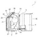
以下に本発明の実施形態を図面を参照して説明する。図1、図2は第1実施形態の空気調和機の斜視図及び側面断面図を示している。尚、図1は外装カバー30(図2参照)を取り外した状態を示している。空気調和機1は室内に配される室内部2と、室内部2に隣接して室外に配される室外部4とを有した一体型に構成される。 Embodiments of the present invention will be described below with reference to the drawings. 1 and 2 show a perspective view and a side sectional view of the air conditioner of the first embodiment. FIG. 1 shows a state in which the exterior cover 30 (see FIG. 2) is removed. The
室内部2の正面には吸込口21が設けられ、室外部4の正面には室外熱交換器42が設けられる。以下の説明において、吸込口21側を前側、室外熱交換器42側を後側(背面側)と称する。また、吸込口21に正面対峙した際の右側及び左側を空気調和機1の右側、左側と称する。 A
室内部2と室外部4とは底板3上に設置され、仕切壁5で前後に分離される。室内部2は底板3、仕切壁5及び外装カバー30によって外側を囲まれた筐体20を形成する。室外部4も同様に底板3、仕切壁5及び外装カバー(不図示)によって外側を囲まれた筐体40を形成する。 The
室外部4には冷凍サイクルを運転する圧縮機41が右側の端部に配される。室外部4の背面には冷媒管47を介して圧縮機41に接続される室外熱交換器42が配される。プロペラファンから成る室外ファン43は室外熱交換器42に対峙して左右方向の中央部に配され、室外熱交換器42を冷却する。室外ファン43及び室外熱交換器42はハウジング44内に配され、ハウジング44によって室外ファン43から気流を室外熱交換器42に導くダクトが形成される。ハウジング44はブラケット45を介して仕切壁5に支持される。 A
室内部2を覆う外装カバー30の前面には吸込口21が開口し、吸込口21の上方には吹出口22が開口する。室内部2内には吸込口21と吹出口22とを連結する送風ダクト24によって送風通路23が形成される。送風ダクト24は外装カバー30を取り外した際に着脱自在のダクト部材29を上部に有し、送風通路23の吹出口22近傍の下壁はダクト部材29により形成されている。 A
送風通路23内にはクロスフローファンから成る室内ファン25(送風機)が設けられる。送風通路23内の吹出口22の近傍には風向を可変するルーバ26が設けられる。室内ファン25と吸込口21との間には冷媒管47を介して圧縮機41に接続される室内熱交換器27が配される。 An indoor fan 25 (blower) composed of a cross flow fan is provided in the
室内ファン25と室内熱交換器27との間には複数のPTCヒータ55(図3参照)を有する加熱部28が配される。室内ファン25によって吸込口21から加熱部28に向かって流通する気流が送風通路23内に形成される。室内熱交換器27及び加熱部28の上方はダクト部材29により覆われる。ダクト部材29を取り外して加熱部28を着脱自在になっている。 A
図3は空気調和機1の構成を示すブロック図である。空気調和機1は各部を制御する制御部50を有している。制御部50には圧縮機41、室内ファン25、室外ファン43、操作部51、記憶部52 電流検知部53及びヒータ制御部54が接続される。ヒータ制御部54には加熱部28のPTCヒータ55が接続される。 FIG. 3 is a block diagram showing the configuration of the
操作部51は筐体20の表面に設けられた操作ボタンやリモートコントローラから成り、空気調和機1の運転指示や設定入力を行う。記憶部52はROM及びRAMから成り、空気調和機1の動作プログラムや設定条件等を記憶するとともに、制御部50の演算の一時記憶を行う。尚、記憶部52を制御部50の外部に接続しているが、制御部50の内部に記憶部52を設けてもよい。 The operation unit 51 includes operation buttons and a remote controller provided on the surface of the
電流検知部53はPTCヒータ55に流れる電流値を検知する。ヒータ制御部54はPTCヒータ55の駆動を制御する。ヒータ制御部54はトライアック回路やリレー回路から成り、PTCヒータ55をDUTY制御する。ヒータ制御部54をトライアック回路により形成するとリレー回路よりもスイッチングの入切音を低減することができるのでより望ましい。PTCヒータ55はPTC特性を有する発熱素子を電極で挟んで形成され、ヒータ制御部54により電極間に駆動電圧が印加されて発熱する。 The
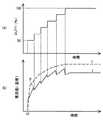
図4、図5(a)、(b)はヒータ制御部54によるPTCヒータ55の駆動制御の動作を示すフローチャート及びタイムチャートである。図5(a)はPTCヒータ55の駆動電圧のDUTY比(単位:%)を示している。図5(b)は電流検知部53により検知される電流値(図中、Iで示す)及びPTCヒータ55の温度(図中、Tで示す)を示している。 4, 5A, and 5B are a flowchart and a time chart showing an operation of driving control of the
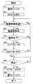
図4のステップ#11では室内ファン25が所定の回転数(例えば、1140rpm)で駆動される。ステップ#12ではDUTY比が50%でPTCヒータ55が駆動開始される(時間t0)。これにより、PTCヒータ55の温度が上昇するとともに、発熱素子がキュリー点に到達するまでPTCヒータ55に流れる電流が増加する。 In
尚、駆動開始時のDUTY比はPTCヒータ55の発熱素子がキュリー点を僅かに超えて抵抗値が増加し始める温度まで昇温されるように設定される。このため、PTCヒータ55の特性や風量に応じて異なるDUTY比が設定される。 The DUTY ratio at the start of driving is set so that the heating element of the
ヒータ制御部54は所定時間の周期で電流検知部53の検知結果を取得し、ステップ#13では該所定時間が経過するまで待機する。所定時間が経過するとステップ#21で電流検知部53で検知された電流値が取得される。ステップ#25では電流検知部53から取得した電流値が前回取得された電流値に対して低下したか否かが判断される。電流検知部53から取得した電流値が前回取得された電流値に対して低下していない場合はステップ#13に戻り、ステップ#13〜#25が繰り返し行われる。 The
PTCヒータ55の温度が上昇して発熱素子がキュリー点を超えると発熱素子の抵抗値が増加し、PTCヒータ55の電流値が極大値P(図5(b)参照)をとる。このため、電流検知部53から取得した電流値が前回取得された電流値に対して低下すると、極大値Pが発生したと判断してステップ#26に移行する。 When the temperature of the
ステップ#26ではPTCヒータ55のDUTY比を10%分(100%に対する10%を表わしている)だけ増加させるDUTY増加処理が行われる。これにより、DUTY比が60%でPTCヒータ55が駆動される。DUTY比の増加によってPTCヒータ55の電流値が再度上昇する。尚、DUTY比の増加量は10%以外でもよい。 In
ステップ#27ではPTCヒータ55のDUTY比が100%に到達したか否かが判断される。PTCヒータ55のDUTY比が100%に到達していない場合はステップ#13に戻り、ステップ#13〜#27が繰り返し行われる。そして、上記と同様に、PTCヒータ55の温度が上昇すると発熱素子の抵抗値が増加してPTCヒータ55の電流値が極大値Pを取る。これにより、PTCヒータ55のDUTY比がステップ#26のDUTY増加処理によって10%分ずつ増加し、電流値が徐々に増加する。 In
PTCヒータ55のDUTY比が100%に到達するとステップ#31に移行し、操作部51による停止の指示があるまでPTCヒータ55の駆動が継続される。停止の指示があるとステップ#32でPTCヒータ55が停止され、ステップ#33で室内ファン25が停止されて終了する。 When the DUTY ratio of the
上記構成の空気調和機1において、冷房運転を開始すると圧縮機41の駆動によって冷凍サイクルが運転される。これにより、室内熱交換器27が冷凍サイクルの低温側の蒸発器となり、室外熱交換器42が冷凍サイクルの高温側の凝縮器となる。室外熱交換器42は室外ファン43により冷却されて放熱する。室内ファン25の駆動によって室内の空気が吸込口21から送風通路23内に流入し、室内熱交換器27と熱交換して降温された空気が吹出口22から室内に送出される。これにより、室内の冷房が行われる。 In the
暖房運転を開始すると圧縮機41の駆動によって冷凍サイクルが運転される。これにより、室内熱交換器27が冷凍サイクルの高温側の凝縮器となり、室外熱交換器42が冷凍サイクルの低温側の蒸発器となる。室外熱交換器42は室外ファン43により昇温される。室内ファン25の駆動によって室内の空気が吸込口21から送風通路23内に流入し、室内熱交換器27と熱交換して昇温される。 When the heating operation is started, the refrigeration cycle is operated by driving the
また、加熱部28が駆動されるとPTCヒータ55が前述の制御方法によって駆動制御され、送風通路23内の空気がPTCヒータ55により更に昇温される。室内熱交換器27及び加熱部28により昇温された空気は吹出口22から室内に送出され、室内の暖房が行われる。暖房運転時に圧縮機41を停止して加熱部28のみによって空気を昇温してもよい。 When the
本実施形態によると、所定のDUTY比でPTCヒータ55の駆動を開始し、PTCヒータ55の電流値が極大値Pとなった際にDUTY比を所定量だけ増加させるDUTY増加処理(ステップ#26)をDUTY比が100%になるまで繰り返すので、駆動開始時にPTCヒータ55が低温であってもDUTY比を増加させるタイミングが速くならず、PTCヒータ55の始動時の過電流を確実に防止することができる。 According to the present embodiment, driving of the
また、電流検知部53によりPTCヒータ55の電流値を所定周期で取得し、前回の電流値に対して低下した際に極大値Pと判断するので、電流値の極大値Pを容易に検知することができる。尚、電流検知部53から取得した電流値が前回の電流値と同じ時に極大値Pが発生したと判断してもよい。 Further, the
次に、図6は第2実施形態の空気調和機1のヒータ制御部54によるPTCヒータ55の駆動制御の動作を示すフローチャートである。本実施形態は前述の図4に示す第1実施形態の動作に対してステップ#22〜#24の処理が追加されている。その他の部分は第1実施形態と同様であるので説明を省略する。 Next, FIG. 6 is a flowchart showing the drive control operation of the
ステップ#21で電流検知部53により検知されたPTCヒータ55の電流値が取得されると、ステップ#22に移行する。ステップ#22では電流検知部53から取得した電流値が所定の電流値I1よりも大きいか否かが判断される。電流値I1は電源容量に基づいて設定され、電流値I1を超えるとPTCヒータ55に流れる電流が大きく、電源容量を超える可能性がある過電流状態となる。 When the current value of the
このため、電流検知部53から取得した電流値が電流値I1よりも大きい場合はステップ#23でPTCヒータ55のDUTY比を10%分だけ下げるDUTY減少処理が行われる。これにより、過電流状態から脱することができ、ステップ#13に戻る。 For this reason, when the current value acquired from the
電流検知部53から取得した電流値が電流値I1よりも大きくない場合はステップ#24で所定の電流値I2よりも小さいか否かが判断される。電流値I2は電流値I1よりも低く設定される。電流検知部53から取得した電流値が電流値I2よりも小さい場合はステップ#25に移行し、極大値Pが検出されるとステップ#26のDUTY増加処理が行われる。 If the current value acquired from the
電流検知部53から取得した電流値が電流値I2よりも小さくない場合はステップ#13に戻る。即ち、極大値Pの発生に拘わらず、PTCヒータ55のDUTY比が維持される。これにより、電流値I1と電流値I2との間ではDUTY比の増減が行われず、過電流状態になることを未然に防ぐことができる。 If the current value acquired from the
本実施形態によると、第1実施形態と同様の効果を得ることができる。加えて、電流検知部53から取得した電流値が電流値I1よりも大きい場合にステップ#23のDUTY減少処理を行うので、PTCヒータ55の過電流状態を脱して電流値が電源容量を超えることをより確実に防止することができる。 According to this embodiment, the same effect as that of the first embodiment can be obtained. In addition, when the current value acquired from the
また、電流検知部53から取得した電流値が電流値I1と電流値I2との間の場合にステップ#26のDUTY増加処理を行わないので、PTCヒータ55が過電流状態になることを未然に防ぐことができる。 In addition, when the current value acquired from the
尚、電流値I1と電流値I2とを一致させ、ステップ#24を省いてもよい。また、ステップ#26のDUTY増加処理によるDUTY比の増加量とステップ#23のDUTY減少処理によるDUTY比の減少量とは異なってもよい。 Note that the current value I1 and the current value I2 may be matched, and
次に、図7は第3実施形態の空気調和機1のヒータ制御部54によるPTCヒータ55の駆動制御の動作を示すフローチャートである。本実施形態は前述の図6に示す第2実施形態の動作に対してステップ#11の動作が異なり、ステップ#28の処理が追加されている。その他の部分は第2実施形態と同様であるので説明を省略する。 Next, FIG. 7 is a flowchart showing the drive control operation of the
ステップ#11では室内ファン25が第1の回転数(例えば、600RPM)で駆動され、ステップ#12でPTCヒータ55がDUTY比50%で駆動される。そして、PTCヒータ55のDUTY比が100%になると、ステップ#28で室内ファン25が第1の回転数よりも大きな第2の回転数(例えば、1140RPM)で駆動される。 In
従って、第2実施形態と同様の効果を得ることができるとともに、始動時の室内ファン25の風量を減らすことによってPTCヒータ55と空気との熱交換が促進される。従って、PTCヒータ55の昇温を速くすることができる。 Accordingly, the same effects as those of the second embodiment can be obtained, and heat exchange between the
また、空気調和機1は設置する際にDUTY比が100%の時の電流値が電源容量よりも低くなるように複数のPTCヒータ55の接続数量が決められる。PTCヒータ55の発熱素子はDUTY比が100%の時よりも70〜80%の時に電流値が最大となる特性を有する場合がある。このため、DUTY比が70〜80%の時に電源容量を超える危険がある。しかし、DUTY比が100%の時に対して室内ファン25の風量を減らすことによってPTCヒータ55の温度を急速に上昇させ、電流値を下げることができる。 Further, when the
次に、図8、図9(a)〜(c)は第4実施形態の空気調和機1のヒータ制御部54によるPTCヒータ55の駆動制御の動作を示すフローチャート及びタイムチャートである。本実施形態は前述の図7に示す第3実施形態の動作に対してステップ#11の動作が異なり、ステップ#14の処理が追加されている。その他の部分は第3実施形態と同様であるので説明を省略する。 Next, FIG. 8, FIG. 9 (a)-(c) is a flowchart and time chart which show the drive control operation | movement of the
図9(a)はPTCヒータ55の駆動電圧のDUTY比(単位:%)を示している。図9(b)は電流検知部53により検知される電流値(図中、Iで示す)及びPTCヒータ55の温度(図中、Tで示す)を示している。図9(c)は室内ファン25の回転数(単位:RPM)を示している。 FIG. 9A shows the DUTY ratio (unit:%) of the drive voltage of the
ステップ#11では室内ファン25が第1の回転数(例えば、900RPM)で駆動され、ステップ#12でPTCヒータ55がDUTY比50%で駆動される。ステップ#13で電流検知部53から電流値を取得する周期が経過すると、ステップ#14で室内ファン25の回転数を所定量だけ低下させる。これにより、室内ファン25の回転数は徐々に低下する。本実施形態では時間t1(例えば、10分)が経過した時に室内ファン25の回転数が900RPMから550RPMになる低下率で低下させている。 In
そして、PTCヒータ55のDUTY比が100%になると、ステップ#28で室内ファン25が第1の回転数よりも大きな第2の回転数(例えば、1140RPM)で駆動される。この時、PTCヒータ55の冷却量が増加してPTCヒータ55の温度Tが若干低下する(前述の第3実施形態も同様である)。 When the DUTY ratio of the
本実施形態によると、第1〜第3実施形態と同様の効果を得ることができる。また、第3実施形態に比してPTCヒータ55の熱交換を促進する度合が弱められる。これにより、発熱素子の熱衝撃が抑制され、クラック等の発生を抑制することができる。従って、PTCヒータ55の短寿命化を抑制しつつ、PTCヒータ55の昇温を速くすることができる。 According to this embodiment, the same effects as those of the first to third embodiments can be obtained. Further, the degree of promoting the heat exchange of the
本発明によると、PTCヒータを有する空気調和機や暖房機等に利用することができる。 According to the present invention, it can be used for an air conditioner or a heater having a PTC heater.
1 空気調和機
2 室内部
3 底板
4 室外部
5 仕切壁
20 筐体
21 吸込口
22 吹出口
23 送風通路
24 送風ダクト
25 室内ファン
26 ルーバー
27 室内熱交換器
28 加熱部
30 外装カバー
41 圧縮機
42 室外熱交換器
43 室外ファン
47 冷媒管
50 制御部
51 操作部
52 記憶部
53 電流検知部
54 ヒータ制御部
55 PTCヒータDESCRIPTION OF
Claims (8)
Translated fromJapanese所定のDUTY比で前記PTCヒータの駆動を開始し、前記電流検知部により検知される前記PTCヒータの電流値を所定周期で取得して前回の電流値に対して同じまたは低下した際に極大値と判断し、
前記電流検知部により検知した電流値が極大値となった際に前記PTCヒータのDUTY比を所定量だけ増加させるDUTY増加処理を行って前記PTCヒータの電流値を上昇させ、
前記DUTY増加処理をDUTY比が100%になるまで繰り返して前記PTCヒータの電流値を徐々に増加させることを特徴とする空気調和機。A PTC heater; a heater control unit that performs DUTY control of the PTC heater; and a current detection unit that detects a current value of the PTC heater, and performs heating operation by sending air heated by the PTC heater into the room In the air conditioner to perform,
The driving of the PTC heater is started at a predetermined DUTY ratio, the current value of the PTC heater detected by the current detection unit is acquired at a predetermined period, and the maximum value when the current value is the same or lower than the previous current value Judging
When the current value detected by the current detection unit reaches a maximum value, a DUTY increase process for increasing the DUTY ratio of the PTC heater by a predetermined amount is performed to increase the current value of the PTC heater,
An air conditioner characterized in that the current value of the PTC heater is gradually increased by repeating the DUTY increasing process until the DUTY ratio reaches 100%.
所定のDUTY比で前記PTCヒータの駆動を開始し、前記電流検知部により検知される前記PTCヒータの電流値を所定周期で取得し、前回の電流値に対して同じまたは低下した際に極大値と判断し、
前記電流検知部により検知した電流値が極大値となった際に前記PTCヒータのDUTY比を所定量だけ増加させるDUTY増加処理をDUTY比が100%になるまで繰り返し、
前記電流検知部により検知した電流値が第1の所定値よりも大きいときに前記PTCヒータのDUTY比を所定量だけ減少させるDUTY減少処理を行い、
前記電流検知部により検知した電流値が第1の所定値よりも低い第2の所定値よりも小さいときに前記DUTY増加処理を行い、
前記電流検知部により検知した電流値が第1の所定値と第2の所定値との間のときに前記PTCヒータのDUTY比の増減を行わないことを特徴とする空気調和機。A PTC heater; a heater control unit that performs DUTY control of the PTC heater; and a current detection unit that detects a current value of the PTC heater, and performs heating operation by sending air heated by the PTC heater into the room In the air conditioner to perform,
The driving of the PTC heater is started at a predetermined DUTY ratio,the current value of the PTC heater detected by the current detection unit is acquired at a predetermined period, and the maximum value when the current value is the same or lower than the previous current value Judging
When the current value detected by the current detector reaches a maximum value, the DUTY increasing process for increasing the DUTY ratio of the PTC heater by a predetermined amount is repeated until the DUTY ratio reaches 100%.
When the current value detected by the current detection unit is greater than a first predetermined value, a DUTY reduction process is performed to decrease the DUTY ratio of the PTC heater by a predetermined amount,
When the current value detected by the current detection unit is smaller than a second predetermined value lower than the first predetermined value, the DUTY increasing process is performed,
An air conditioner characterized by not increasing or decreasing the DUTY ratio of the PTC heater when the current value detected by the current detection unit is between a first predetermined value and a second predetermined value.
Priority Applications (4)
| Application Number | Priority Date | Filing Date | Title |
|---|---|---|---|
| JP2009268882AJP5122550B2 (en) | 2009-11-26 | 2009-11-26 | PTC heater control method and air conditioner |
| US12/953,990US9182134B2 (en) | 2009-11-26 | 2010-11-24 | Air conditioner having positive temperature coefficient heater |
| CA 2722746CA2722746C (en) | 2009-11-26 | 2010-11-24 | Air conditioner |
| CN2010105673955ACN102080866B (en) | 2009-11-26 | 2010-11-26 | Air conditioner and method for controlling positive temperature coefficient (ptc) heater |
Applications Claiming Priority (1)
| Application Number | Priority Date | Filing Date | Title |
|---|---|---|---|
| JP2009268882AJP5122550B2 (en) | 2009-11-26 | 2009-11-26 | PTC heater control method and air conditioner |
Publications (2)
| Publication Number | Publication Date |
|---|---|
| JP2011112281A JP2011112281A (en) | 2011-06-09 |
| JP5122550B2true JP5122550B2 (en) | 2013-01-16 |
Family
ID=44062153
Family Applications (1)
| Application Number | Title | Priority Date | Filing Date |
|---|---|---|---|
| JP2009268882AExpired - Fee RelatedJP5122550B2 (en) | 2009-11-26 | 2009-11-26 | PTC heater control method and air conditioner |
Country Status (4)
| Country | Link |
|---|---|
| US (1) | US9182134B2 (en) |
| JP (1) | JP5122550B2 (en) |
| CN (1) | CN102080866B (en) |
| CA (1) | CA2722746C (en) |
Families Citing this family (20)
| Publication number | Priority date | Publication date | Assignee | Title |
|---|---|---|---|---|
| GB0903682D0 (en) | 2009-03-04 | 2009-04-15 | Dyson Technology Ltd | A fan |
| JP5122550B2 (en)* | 2009-11-26 | 2013-01-16 | シャープ株式会社 | PTC heater control method and air conditioner |
| JP5027863B2 (en)* | 2009-11-26 | 2012-09-19 | シャープ株式会社 | Air conditioner |
| JP5221596B2 (en)* | 2010-06-10 | 2013-06-26 | シャープ株式会社 | Air conditioner |
| GB2482547A (en) | 2010-08-06 | 2012-02-08 | Dyson Technology Ltd | A fan assembly with a heater |
| GB2482548A (en) | 2010-08-06 | 2012-02-08 | Dyson Technology Ltd | A fan assembly with a heater |
| CN103062859B (en)* | 2011-10-19 | 2015-06-10 | 珠海格力电器股份有限公司 | Air conditioner with auxiliary heating system and control method thereof |
| GB2500903B (en)* | 2012-04-04 | 2015-06-24 | Dyson Technology Ltd | Heating apparatus |
| GB2501301B (en) | 2012-04-19 | 2016-02-03 | Dyson Technology Ltd | A fan assembly |
| WO2014114330A1 (en)* | 2013-01-23 | 2014-07-31 | Stadler Form Aktiengesellschaft | Heating device comprising an electrically heatable ptc element and method for operating such a heating device |
| US10085584B2 (en)* | 2014-06-09 | 2018-10-02 | Whirlpool Corporation | Method of regulating temperature for sous vide cooking and apparatus therefor |
| CN104880602B (en)* | 2015-04-30 | 2017-11-10 | 广东美的制冷设备有限公司 | A kind of air conditioner and its electric heating device detection method and device |
| CN105423513B (en)* | 2015-12-30 | 2018-04-10 | 四川长虹空调有限公司 | Power continuously adjustabe electric heating system and its control method |
| CN106347067B (en)* | 2016-07-29 | 2018-09-11 | 北京新能源汽车股份有限公司 | Electric automobile and control method and system for PTC electric heater of electric automobile |
| CN108731147A (en)* | 2018-04-02 | 2018-11-02 | 霍尼韦尔环境自控产品(天津)有限公司 | Heating control apparatus and method for air purifier |
| CN110398049B (en)* | 2019-07-26 | 2021-03-19 | 广东美的暖通设备有限公司 | Air conditioner control method, air conditioner and computer readable storage medium |
| CN111237997B (en)* | 2020-01-19 | 2021-04-20 | 广东美的制冷设备有限公司 | Air conditioner and control method and control device thereof |
| JP2022161049A (en)* | 2021-04-08 | 2022-10-21 | パナソニックIpマネジメント株式会社 | air conditioner |
| DE102021207253A1 (en)* | 2021-07-08 | 2023-01-12 | Mahle International Gmbh | Method of regulating a heater and the heater |
| JP2023044050A (en)* | 2021-09-17 | 2023-03-30 | パナソニックIpマネジメント株式会社 | air conditioner |
Family Cites Families (45)
| Publication number | Priority date | Publication date | Assignee | Title |
|---|---|---|---|---|
| GB1074296A (en)* | 1964-03-09 | 1967-07-05 | Ranco Inc | Condition responsive motor speed control circuits |
| US4459519A (en)* | 1974-06-24 | 1984-07-10 | General Electric Company | Electronically commutated motor systems and control therefor |
| US4285210A (en)* | 1980-04-28 | 1981-08-25 | General Electric Company | Self-contained heating and cooling apparatus |
| US4346755A (en)* | 1980-05-21 | 1982-08-31 | General Electric Company | Two stage control circuit for reversible air cycle heat pump |
| JPS6012532B2 (en)* | 1980-10-13 | 1985-04-02 | 株式会社東芝 | Air conditioner control method |
| US4439995A (en)* | 1982-04-05 | 1984-04-03 | General Electric Company | Air conditioning heat pump system having an initial frost monitoring control means |
| JPS62129639A (en)* | 1985-11-29 | 1987-06-11 | Toshiba Corp | air conditioner |
| JPS60142140A (en)* | 1983-12-28 | 1985-07-27 | Matsushita Electric Ind Co Ltd | Air conditioner |
| US4534179A (en)* | 1984-10-04 | 1985-08-13 | General Electric Company | Air conditioning apparatus |
| US4732009A (en)* | 1986-06-26 | 1988-03-22 | Whirlpool Corporation | Refrigerator compartment and method for accurately controlled temperature |
| JP2601514B2 (en) | 1988-04-27 | 1997-04-16 | 出光興産株式会社 | Lubricating oil composition |
| JPH037853A (en)* | 1989-06-05 | 1991-01-16 | Toshiba Corp | air conditioner |
| JPH0820094B2 (en)* | 1989-08-24 | 1996-03-04 | シャープ株式会社 | Air conditioner |
| JPH04240337A (en)* | 1991-01-21 | 1992-08-27 | Fujitsu General Ltd | air conditioner |
| KR960001985B1 (en)* | 1991-06-07 | 1996-02-08 | 삼성전자주식회사 | Refrigerator |
| US5592647A (en)* | 1991-08-26 | 1997-01-07 | Nippon Tungsten Co., Ltd. | PTC panel heater with small rush current characteristic and highly heat insulating region corresponding to heater location to prevent local overheating |
| KR940002220B1 (en)* | 1991-09-12 | 1994-03-19 | 주식회사 금성사 | Temperature control method in refrigerator |
| JP3167372B2 (en)* | 1991-10-11 | 2001-05-21 | 東芝キヤリア株式会社 | Air conditioner |
| JPH05118719A (en)* | 1991-10-15 | 1993-05-14 | Sanden Corp | Revolution control of motor-driven compressor |
| KR0133053B1 (en)* | 1992-06-18 | 1998-04-21 | 강진구 | Compressor Operation Frequency Control Method of Air Conditioner |
| US5255530A (en)* | 1992-11-09 | 1993-10-26 | Whirlpool Corporation | System of two zone refrigerator temperature control |
| DE69309645T2 (en)* | 1992-12-21 | 1997-10-02 | Matsushita Electric Ind Co Ltd | Method and apparatus for heating with microwaves |
| JPH07332740A (en)* | 1994-06-03 | 1995-12-22 | Toshiba Corp | Air conditioner operation control method |
| JPH08152179A (en) | 1994-11-28 | 1996-06-11 | Hitachi Ltd | Control method of air conditioner using PTC heater |
| KR0176692B1 (en)* | 1996-04-29 | 1999-10-01 | 윤종용 | Temp.control method and device thereof in ref. |
| DK174114B1 (en)* | 1996-10-09 | 2002-06-24 | Danfoss Compressors Gmbh | Method for speed control of a compressor as well as control using the method |
| KR19980083487A (en)* | 1997-05-15 | 1998-12-05 | 윤종용 | Refrigeration control device and method |
| GB2342711B (en)* | 1998-10-12 | 2003-01-22 | Delphi Tech Inc | Air conditioning system for a motor vehicle |
| JP3609286B2 (en) | 1999-05-25 | 2005-01-12 | シャープ株式会社 | Air conditioning equipment |
| BE1013150A3 (en)* | 1999-11-24 | 2001-10-02 | Atlas Copco Airpower Nv | Device and method for cool drying. |
| US6516622B1 (en)* | 2000-06-13 | 2003-02-11 | Belair Technologies, Llc | Method and apparatus for variable frequency controlled compressor and fan |
| JP4782941B2 (en)* | 2001-05-16 | 2011-09-28 | サンデン株式会社 | Air conditioner for vehicles |
| JP2003059623A (en)* | 2001-08-17 | 2003-02-28 | Nippon Dainatekku Kk | Current control method, and current control device for practicing current control method |
| US7036329B2 (en)* | 2003-11-17 | 2006-05-02 | Delphi Technologies, Inc. | Lowering of refrigerant emissions by cycling of a variable displacement compressor |
| DE202004007039U1 (en)* | 2004-05-03 | 2005-06-30 | Eichenauer Heizelemente Gmbh & Co. Kg | Device for separating fluid flows in a heating device |
| US7340910B2 (en)* | 2004-06-02 | 2008-03-11 | Thompson Thomas W | System and method of increasing efficiency of heat pumps |
| KR100697195B1 (en)* | 2004-12-28 | 2007-03-21 | 엘지전자 주식회사 | Unitary air conditioner and its variable driving control method |
| KR100697196B1 (en)* | 2004-12-28 | 2007-03-21 | 엘지전자 주식회사 | Compressor rapid on / off prevention control method of unit air conditioner |
| US7730731B1 (en)* | 2005-11-01 | 2010-06-08 | Hewlett-Packard Development Company, L.P. | Refrigeration system with serial evaporators |
| US7739882B2 (en)* | 2006-02-28 | 2010-06-22 | Dometic, LLC | Variable speed control |
| US20080124060A1 (en)* | 2006-11-29 | 2008-05-29 | Tianyu Gao | PTC airflow heater |
| JP5027863B2 (en)* | 2009-11-26 | 2012-09-19 | シャープ株式会社 | Air conditioner |
| JP5122550B2 (en)* | 2009-11-26 | 2013-01-16 | シャープ株式会社 | PTC heater control method and air conditioner |
| US8309894B2 (en)* | 2010-02-12 | 2012-11-13 | General Electric Company | Triac control of positive temperature coefficient (PTC) heaters in room air conditioners |
| JP5221596B2 (en)* | 2010-06-10 | 2013-06-26 | シャープ株式会社 | Air conditioner |
- 2009
- 2009-11-26JPJP2009268882Apatent/JP5122550B2/ennot_activeExpired - Fee Related
- 2010
- 2010-11-24CACA 2722746patent/CA2722746C/ennot_activeExpired - Fee Related
- 2010-11-24USUS12/953,990patent/US9182134B2/ennot_activeExpired - Fee Related
- 2010-11-26CNCN2010105673955Apatent/CN102080866B/ennot_activeExpired - Fee Related
Also Published As
| Publication number | Publication date |
|---|---|
| CA2722746C (en) | 2015-04-14 |
| JP2011112281A (en) | 2011-06-09 |
| CA2722746A1 (en) | 2011-05-26 |
| US20110123181A1 (en) | 2011-05-26 |
| CN102080866A (en) | 2011-06-01 |
| CN102080866B (en) | 2013-12-04 |
| US9182134B2 (en) | 2015-11-10 |
Similar Documents
| Publication | Publication Date | Title |
|---|---|---|
| JP5122550B2 (en) | PTC heater control method and air conditioner | |
| JP5221596B2 (en) | Air conditioner | |
| JP6397050B2 (en) | Air conditioner | |
| EP2525102A2 (en) | Air volume adjustment device for air conditioner | |
| JP6401585B2 (en) | Air conditioner | |
| JP2009287895A (en) | Heat pump hot water heating system | |
| JP2009023482A (en) | Rear unit and its control device | |
| JP6051416B2 (en) | Simple inverter control type refrigerator, inverter control unit for refrigerator, and inverter compressor using the same | |
| CN110671780A (en) | Air conditioner control method and device and air conditioner | |
| JP2013044248A (en) | Cooling control device for engine | |
| CN112556248A (en) | Self-cleaning method of automobile air conditioner heat pump system | |
| JP4549242B2 (en) | Air conditioner | |
| CN115218294B (en) | Chip cooling control method for air conditioner | |
| JPS621499B2 (en) | ||
| JPH10122626A (en) | Air conditioner | |
| JP2006153320A (en) | Outdoor unit for air conditioning device | |
| JPH01247940A (en) | Air conditioner | |
| JP2639267B2 (en) | Operation control device for air conditioner | |
| KR0177691B1 (en) | Control method of compressor operation of inverter air conditioner | |
| JP2009229004A (en) | Air conditioner | |
| JPH043844A (en) | Method of controlling air conditioner | |
| JP2011202883A (en) | Heat source machine of refrigeration cycle device | |
| CN119958011A (en) | Air conditioner outdoor unit and control method thereof | |
| CN119353713A (en) | Heater control method, device, readable storage medium and heater | |
| CN120403011A (en) | Air conditioner and control method thereof |
Legal Events
| Date | Code | Title | Description |
|---|---|---|---|
| A977 | Report on retrieval | Free format text:JAPANESE INTERMEDIATE CODE: A971007 Effective date:20110902 | |
| A131 | Notification of reasons for refusal | Free format text:JAPANESE INTERMEDIATE CODE: A131 Effective date:20110913 | |
| A521 | Request for written amendment filed | Free format text:JAPANESE INTERMEDIATE CODE: A523 Effective date:20111109 | |
| A131 | Notification of reasons for refusal | Free format text:JAPANESE INTERMEDIATE CODE: A131 Effective date:20120522 | |
| A521 | Request for written amendment filed | Free format text:JAPANESE INTERMEDIATE CODE: A523 Effective date:20120625 | |
| TRDD | Decision of grant or rejection written | ||
| A01 | Written decision to grant a patent or to grant a registration (utility model) | Free format text:JAPANESE INTERMEDIATE CODE: A01 Effective date:20121002 | |
| A01 | Written decision to grant a patent or to grant a registration (utility model) | Free format text:JAPANESE INTERMEDIATE CODE: A01 | |
| A61 | First payment of annual fees (during grant procedure) | Free format text:JAPANESE INTERMEDIATE CODE: A61 Effective date:20121024 | |
| FPAY | Renewal fee payment (event date is renewal date of database) | Free format text:PAYMENT UNTIL: 20151102 Year of fee payment:3 | |
| R150 | Certificate of patent or registration of utility model | Ref document number:5122550 Country of ref document:JP Free format text:JAPANESE INTERMEDIATE CODE: R150 Free format text:JAPANESE INTERMEDIATE CODE: R150 | |
| S531 | Written request for registration of change of domicile | Free format text:JAPANESE INTERMEDIATE CODE: R313531 | |
| R350 | Written notification of registration of transfer | Free format text:JAPANESE INTERMEDIATE CODE: R350 | |
| LAPS | Cancellation because of no payment of annual fees |