JP5121838B2 - Radio base station apparatus and transmission control method - Google Patents
Radio base station apparatus and transmission control methodDownload PDFInfo
- Publication number
- JP5121838B2 JP5121838B2JP2009534178AJP2009534178AJP5121838B2JP 5121838 B2JP5121838 B2JP 5121838B2JP 2009534178 AJP2009534178 AJP 2009534178AJP 2009534178 AJP2009534178 AJP 2009534178AJP 5121838 B2JP5121838 B2JP 5121838B2
- Authority
- JP
- Japan
- Prior art keywords
- cell
- interference
- base station
- transmission
- power
- Prior art date
- Legal status (The legal status is an assumption and is not a legal conclusion. Google has not performed a legal analysis and makes no representation as to the accuracy of the status listed.)
- Expired - Fee Related
Links
Images


Classifications
- H—ELECTRICITY
- H04—ELECTRIC COMMUNICATION TECHNIQUE
- H04W—WIRELESS COMMUNICATION NETWORKS
- H04W72/00—Local resource management
- H04W72/50—Allocation or scheduling criteria for wireless resources
- H04W72/54—Allocation or scheduling criteria for wireless resources based on quality criteria
- H04W72/541—Allocation or scheduling criteria for wireless resources based on quality criteria using the level of interference
- H—ELECTRICITY
- H04—ELECTRIC COMMUNICATION TECHNIQUE
- H04L—TRANSMISSION OF DIGITAL INFORMATION, e.g. TELEGRAPHIC COMMUNICATION
- H04L5/00—Arrangements affording multiple use of the transmission path
- H04L5/003—Arrangements for allocating sub-channels of the transmission path
- H04L5/0032—Distributed allocation, i.e. involving a plurality of allocating devices, each making partial allocation
- H—ELECTRICITY
- H04—ELECTRIC COMMUNICATION TECHNIQUE
- H04W—WIRELESS COMMUNICATION NETWORKS
- H04W52/00—Power management, e.g. Transmission Power Control [TPC] or power classes
- H04W52/04—Transmission power control [TPC]
- H04W52/18—TPC being performed according to specific parameters
- H04W52/24—TPC being performed according to specific parameters using SIR [Signal to Interference Ratio] or other wireless path parameters
- H04W52/243—TPC being performed according to specific parameters using SIR [Signal to Interference Ratio] or other wireless path parameters taking into account interferences
- H—ELECTRICITY
- H04—ELECTRIC COMMUNICATION TECHNIQUE
- H04W—WIRELESS COMMUNICATION NETWORKS
- H04W72/00—Local resource management
- H04W72/20—Control channels or signalling for resource management
- H04W72/21—Control channels or signalling for resource management in the uplink direction of a wireless link, i.e. towards the network
Landscapes
- Engineering & Computer Science (AREA)
- Quality & Reliability (AREA)
- Computer Networks & Wireless Communication (AREA)
- Signal Processing (AREA)
- Mobile Radio Communication Systems (AREA)
Description
Translated fromJapanese本発明は、無線基地局装置及び送信制御方法に関し、特にアダプティブFFR(fractional frequency reuse)が適用される無線基地局装置及び送信制御方法に関する。The present invention relates to aradio base station apparatus and a transmission control method , and more particularly to aradio base station apparatus and a transmission control method to which adaptive FFR (fractional frequency reuse) is applied.
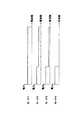
セル間干渉に起因するスループット劣化を改善する技術として、Adaptive FFR(Fractional Frequency Reuse)が提案されている。Adaptive FFRでは、送信利用帯域が、高電力送信帯域と低電力送信帯域とに分割される。低電力送信帯域では、送信電力が段階的に可変となっており、各段階に対応したモードが用意されている(図1参照)。 Adaptive FFR (Fractional Frequency Reuse) has been proposed as a technique for improving throughput degradation caused by inter-cell interference. In Adaptive FFR, the transmission use band is divided into a high power transmission band and a low power transmission band. In the low power transmission band, the transmission power is variable in stages, and a mode corresponding to each stage is prepared (see FIG. 1).
このAdaptive FFRが適用される無線通信システムにおいて、基地局(NB)は、無線端末(UE)から送信される干渉レポートに基づいてモードを選択し、この選択されたモードに対応する送信パワーに変更した上で下りの送信を行う。その後、隣接するNBへモードを変更したことが通知され、これに応じて隣接のNBでもモードの変更が行われる。ここで、モードの番号を上げることは、リユースファクタを下げることに相当する。 In a radio communication system to which this adaptive FFR is applied, a base station (NB) selects a mode based on an interference report transmitted from a radio terminal (UE), and changes the transmission power to correspond to the selected mode. Then, downlink transmission is performed. Thereafter, the adjacent NB is notified that the mode has been changed, and the mode is also changed in the adjacent NB accordingly. Here, increasing the mode number corresponds to decreasing the reuse factor.
こうして隣接セル間の干渉を排除して、スループットを改善することができる。
しかしながら、モードを変更する際に、基地局間でモード変更通知が通信されて初めて隣接セル全体のモード変更がなされるため、セル間干渉が改善されるまでに遅延が発生してしまう。この基地局間の通信による遅延により、システムスループットが劣化する問題がある。 However, when the mode is changed, since the mode change of the entire adjacent cell is made only after the mode change notification is communicated between the base stations, a delay occurs until the inter-cell interference is improved. There is a problem that the system throughput deteriorates due to a delay caused by communication between the base stations.
本発明の目的は、セル間干渉が改善されるまでの時間を短縮してシステムスループットを向上する無線基地局装置及び送信制御方法を提供することである。An object of the present invention is to provide anon-linear base station apparatus置及 beauty transmission controlhow to increase system throughput by shortening the time until inter-cell interference is improved.
本発明の無線基地局装置は、自装置がカバーする自セルに隣接する複数の隣接セルに存在する複数の無線端末の各々にて下り回線の受信品質に基づいて複数のキャリアの中から選択されたキャリアを用いて、前記複数の無線端末から送信された複数の干渉レポートを受信する受信手段と、前記複数の干渉レポートの受信電力分布に基づいて、前記自セルの下り回線におけるアダプティブFFR処理を制御するアダプティブFFR制御手段と、を具備する構成を採る。また、本発明の無線基地局装置は、自装置がカバーする自セルに隣接する複数の隣接セルのそれぞれに対応づけられた複数のキャリアの中から前記複数の隣接セルのそれぞれに基づいて選択されたキャリアを用いて、複数の無線端末から送信された複数の干渉レポートを受信する受信手段と、前記複数の干渉レポートの受信電力分布に基づいて、前記自セルの下り回線におけるアダプティブFFR処理を制御するアダプティブFFR制御手段と、を具備する構成を採る。The radio base station apparatus of the present invention is selected from a plurality of carriers based on downlink reception quality at each of a plurality of radio terminals existing in a plurality of adjacent cells adjacent to the own cell covered by the own apparatus. And receiving means for receiving a plurality of interference reports transmitted from the plurality ofradio terminals using the received carrier, and adaptive FFR processing in the downlink of the own cell based on the received power distribution of the plurality of interference reports. And an adaptive FFR control means for controlling. Further, the radio base station apparatus of the present invention is selected based on each of the plurality of neighboring cells from among a plurality of carriers associated with each of a plurality of neighboring cells adjacent to the own cell covered by the own apparatus. by using thecarrier, receiving means for receiving a plurality of interference reports transmitted frommultipleradio terminals, based on the received power distribution of the plurality of interference reports, adaptive FFR processing in downlink of the local cell And an adaptive FFR control means for controlling.
本発明の送信制御方法は、基地局装置がカバーする自セルに隣接する複数の隣接セルに存在する複数の無線端末の各々にて下り回線の受信品質に基づいて複数のキャリアの中から選択されたキャリアを用いて、前記複数の無線端末から送信された複数の干渉レポートを受信する受信ステップと、前記複数の干渉レポートの受信電力分布に基づいて、前記自セルにおけるアダプティブFFR処理を制御する制御ステップと、を具備する。また、本発明の送信制御方法は、基地局装置がカバーする自セルに隣接する複数の隣接セルのそれぞれに対応付けられた複数のキャリアの中から前記複数の隣接セルのそれぞれに基づいて選択されたキャリアを用いて、複数の無線端末から送信された複数の干渉レポートを受信する受信ステップと、前記複数の干渉レポートの受信電力分布に基づいて、前記自セルにおけるアダプティブFFR処理を制御する制御ステップと、を具備する。The transmission control method of the present invention is selected from a plurality of carriers on the basis of downlink reception quality in each of aplurality of radio terminals existing in aplurality of adjacent cells adjacent to the own cell covered by the base station apparatus. A reception step of receiving a plurality of interference reports transmitted from the plurality ofwireless terminals using a carrier, and a control for controlling adaptive FFR processing in the own cell based on a received power distribution of the plurality of interference reports Steps. The transmission control method of the present invention is selected based on each of the plurality of neighboring cells from among a plurality of carriers associated with each of a plurality of neighboring cells adjacent to the own cell covered by the base station apparatus. by using thecarrier, a receiving step of receiving a plurality of interference reports transmitted frommultipleradio terminals, based on the received power distribution of the plurality of interference reports, which controls adaptive FFR processing in the own cell control Steps.
本発明によれば、セル間干渉が改善されるまでの時間を短縮してシステムスループットを向上する無線基地局装置及び送信制御方法を提供することができる。According to the present invention, it is possible to provide anon-linear base station apparatus置及 beauty transmission controlhow to increase system throughput by shortening the time until inter-cell interference is improved.
以下、本発明の実施の形態について図面を参照して詳細に説明する。なお、実施の形態において、同一の構成要素には同一の符号を付し、その説明は重複するので省略する。 Hereinafter, embodiments of the present invention will be described in detail with reference to the drawings. In the embodiment, the same components are denoted by the same reference numerals, and the description thereof will be omitted because it is duplicated.
(実施の形態1)
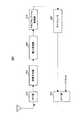
図2に示すように本実施の形態の無線端末(UE)100は、FFT部110と、干渉電力測定部120と、干渉レポート生成部130と、変調部140と、マッピング部150と、IFFT部160とを有する。(Embodiment 1)
As shown in FIG. 2, radio terminal (UE) 100 of this embodiment includes an
FFT部110は、アンテナを介して受信したOFDM信号を入力とし、入力信号に対してフーリエ変換を施す。フーリエ変換後の信号は、干渉電力測定部120に送出される。また、入力OFDM信号は、無線受信信号が無線受信処理部(図示せず)にて所定の無線受信処理(ダウンコンバート、A/D変換など)を施されたものである。 The
干渉電力測定部120は、フーリエ変換後の受信信号を用いて、受信対象の信号(所望信号)以外の干渉信号に係る電力(干渉電力)を測定する。干渉電力測定部120は、干渉電力測定値を干渉レポート生成部130に送出する。 The interference
干渉レポート生成部130は、干渉電力測定部120から受け取る干渉電力測定値に応じた干渉レポート信号を生成する。干渉レポート生成部130は、干渉電力測定値がレポート生成判断しきい値よりも大きい場合、干渉があると判断し、干渉レポート信号を生成する。例えば、干渉があると判断される場合には、ビット「1」を表す1ビットの信号が干渉レポート信号として生成される。一方、干渉がないと判断される場合には、ビット「0」を表す1ビットの信号が干渉レポート信号として生成される。 The interference
変調部140は、干渉レポート生成部130にて生成された干渉レポート信号を変調し、変調後の干渉レポート信号をマッピング部150に送出する。
マッピング部150は、変調部140から受け取る干渉レポート信号を、所定の「無線リソース」にマッピングする。ここで「無線リソース」は、キャリア、タイミング、及び、拡散コードにより規定される。 The
IFFT部160は、干渉レポートがマッピングされた信号系列を周波数領域から時間領域に変換することにより、OFDM信号を形成する。このOFDM信号は、無線送信部(図示せず)で所定の無線送信処理(D/A変換、アップコンバートなど)を施され、アンテナを介して送信される。 The
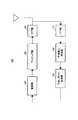
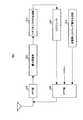
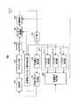
図3に示すように本実施の形態の基地局(NB)200は、FFT部210と、電力測定部220と、アダプティブFFR(fractional frequency reuse)処理部230と、スケジューラ240と、IFFT部250とを有する。 As shown in FIG. 3, the base station (NB) 200 of this embodiment includes an
FFT部210は、アンテナを介して受信したOFDM信号を入力とし、入力信号に対してフーリエ変換を施す。フーリエ変換後の受信信号は、電力測定部220に送出される。また、入力OFDM信号は、無線受信信号が無線受信処理部(図示せず)にて所定の無線受信処理(ダウンコンバート、A/D変換など)を施されたものである。 The
電力測定部220は、上記干渉レポート信号が重畳される所定の無線リソースにおける電力を測定する。この所定の無線リソースは、基地局200のセル(自セル)に隣接するセル(隣接セル)内に存在する無線端末100で共通する。このため、この所定の無線リソースを「共通無線リソース」と呼ぶことがある。なお本実施の形態では、自セル内に存在する無線端末100も、この「共通無線リソース」を使用する。 The
アダプティブFFR処理部230は、無線端末100から送信された干渉レポートに基づいて、アダプティブFFR処理を制御する。 The adaptive
アダプティブFFR処理部230は、電力測定部220にて測定された、共通無線リソースの測定電力値と、モード変更判断しきい値とを比較し、この比較結果に基づいて送信モードを変更する。アダプティブFFR処理部230は、共通無線リソースの測定電力値がモード変更判断しきい値よりも大きい場合、隣接セルでは他セルから受ける干渉が大きいと判断し、自セルから隣接セルへ与える干渉が小さくなるように送信モードを変更する。 The adaptive
例えば、背景技術の説明にある送信モードでは、モードの番号が大きくなる程、低電力送信帯域の送信電力が小さく設定される。すなわち、モードの番号が大きくなる程、リユースファクタが小さく設定される。このような送信モードが基地局200に用意されている場合には、アダプティブFFR処理部230は、現在設定されているモードよりも一つ番号の大きいモードに、送信モードを変更する。すなわち、アダプティブFFR処理部230は、現在設定されているリユースファクタよりも一つ小さいリユースファクタに変更する。 For example, in the transmission mode described in the background art, the transmission power of the low power transmission band is set to be smaller as the mode number is larger. That is, the reuse factor is set smaller as the mode number increases. When such a transmission mode is prepared in the
スケジューラ240は、モード変更後、自セル内にある無線端末100に対応する下りリソースの割当を変更する。スケジューラ240は、その割当に従って、下り回線の送信信号系列を形成する。 The
IFFT部250は、スケジューラ240にて形成された送信信号系列とパイロット信号とを入力とし、入力信号に対して逆フーリエ変換を施すことによりOFDM信号を形成する。このOFDM信号は、無線送信部(図示せず)で所定の無線送信処理(D/A変換、アップコンバートなど)を施され、アンテナを介して送信される。 IFFT
次に、上記構成を有する無線端末100及び基地局200から構成される無線通信システムについて説明する。 Next, a radio communication system including
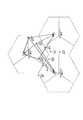
図4に示すように無線通信システムは、1つの基地局200のセルの周りを隣接セルが取り囲み、各隣接セルには他の基地局200が配置されている。同図では、セルAの基地局200をNB−Aと表し、同様にセルBの基地局200をNB−B、セルCの基地局200をNB−Cと表す。セルAには、それぞれ無線端末100である、UE−A,B,Cが存在している。セルBには、UE−D,E,Fが存在し、セルCには、UE−G,H,Iが存在している。 As shown in FIG. 4, in the wireless communication system, adjacent cells surround a cell of one
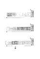
NB−Aは、セルAの隣接セルであるセルB,Cに存在するUE−D,E,F,G,H,Iから、共通無線リソースを用いて送信された干渉レポートを受信する。本実施の形態では、共通無線リソースとして、特定の1つのサブキャリアが用いられる(図5参照)。さらに、そのサブキャリアには、干渉レポートが随時重畳されるのではなく、フレームの一部、例えばフレームにおける特定の1シンボルにだけ重畳される(図6参照)。また、本実施の形態では、NB−Aは、自セルに存在するUE−A,B,Cから、その共通無線リソースを用いて送信された干渉レポートを受信する。 NB-A receives an interference report transmitted using common radio resources from UE-D, E, F, G, H, and I existing in cells B and C that are neighboring cells of cell A. In the present embodiment, one specific subcarrier is used as the common radio resource (see FIG. 5). Further, an interference report is not superimposed on the subcarriers as needed, but only on a part of the frame, for example, a specific symbol in the frame (see FIG. 6). Moreover, in this Embodiment, NB-A receives the interference report transmitted using the common radio | wireless resource from UE-A, B, C which exists in an own cell.
すなわち、図7に示すようにNB−Aは、自セル及び隣接セルに存在するUEから、共通無線リソースを用いて送信された干渉レポートを受信する。同様に、NB−B,Cもそれぞれ、自セル及び隣接セルに存在するUEから、共通無線リソースを用いて送信された干渉レポートを受信する。 That is, as shown in FIG. 7, NB-A receives the interference report transmitted using the common radio | wireless resource from UE which exists in a self-cell and an adjacent cell. Similarly, each of NB-B and C receives an interference report transmitted using common radio resources from UEs existing in its own cell and neighboring cells.
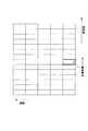
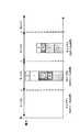
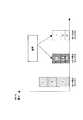
NB−A,B,Cのそれぞれの電力測定部220では、図8に示すように共通無線リソースで送信された干渉レポートの受信電力が測定される。すなわち、自セル及び隣接セルに存在するUEから共通無線リソースで送信された各干渉レポートの受信電力が足し合わされて合成された合成受信電力が測定される。 In each of the
そして、図9に示すようにNB−A,B,CのそれぞれのアダプティブFFR処理部230は、その合成受信電力に基づいて、アダプティブFFR処理を制御する。同図には、セルAの場合が示されている。 And as shown in FIG. 9, each adaptive
まず、NB−Aは、セルAに存在するUEに対して、基準信号(RS:reference signal)とデータとを送信する。この送信信号は、他のUEにとって干渉信号である。セルA及びこの隣接セルに存在するUEは、干渉レポート生成部130にて生成する干渉レポートを共通無線リソースを用いて送信する。 First, NB-A transmits a reference signal (RS) and data to UEs existing in cell A. This transmission signal is an interference signal for other UEs. The UE existing in the cell A and the adjacent cell transmits the interference report generated by the interference
このときNB−Aの電力測定部220にて測定される共通無線リソースの合成受信電力が図9左図のような場合、合成受信電力は、モード変更判断しきい値を超えた状況となっている。このため、アダプティブFFR処理部230は、隣接セルでは他セルから受ける干渉が大きいと判断し、自セルから隣接セルへ与える干渉が小さくなるように送信モードを変更する。この場合、モードの番号が1段階上げられる。 At this time, if the combined received power of the common radio resource measured by the
この送信モードの変更後、NB−Aのスケジューラ240は、自セル内にある無線端末100に対応する下りリソースの割当を変更した上で、RSとデータとを送信する。そして、セルA及びこの隣接セルに存在するUEは、干渉レポート生成部130にて生成する干渉レポートを共通無線リソースを用いて送信する。 After the change of the transmission mode, the
NB−Aの電力測定部220にて測定される共通無線リソースの合成受信電力が図9中央図のような場合、合成受信電力は、モード変更判断しきい値をまだ超えた状況となっている。このため、送信モードの番号がもう1段階上げられる。 When the combined received power of the common radio resource measured by the
この送信モードの変更後、再度、RSとデータとが送信され、さらに、干渉レポートの送信が行われる。 After the change of the transmission mode, RS and data are transmitted again, and further an interference report is transmitted.
NB−Aの電力測定部220にて測定される共通無線リソースの合成受信電力が図9右図のような場合、合成受信電力は、モード変更判断しきい値より小さい。この場合には、アダプティブFFR処理部230は、現在の送信モードより番号が小さいモードが存在すれば、送信モードを1段階下げる処理を行う。 When the combined received power of the common radio resource measured by the NB-A
このように本実施の形態によれば、基地局200では、干渉レポート受信手段としての無線受信部(図示せず)及びFFT部210が、それぞれ異なる隣接セルに存在する複数の無線端末100から隣接セルの間で共通する共通無線リソースを用いて送信された、干渉レポートを受信し、アダプティブFFR処理部230が、受信干渉レポートに基づいて、自セルの下り回線におけるアダプティブFFR処理を制御する。 Thus, according to the present embodiment, in
こうして隣接セルに存在する無線端末100から直接的に干渉レポートの報告を受けて、隣接セルの干渉状況を考慮した上で送信モードの変更を行うことができる。このため、従来、隣接する基地局200の間で行われていた送信モード変更の報告を行う必要がなくなる。その結果、システムで必要なシグナリングが削減されるので、システムスループットを向上することができる。 In this way, it is possible to receive the report of the interference report directly from the
さらに本実施の形態では、共通無線リソースとして、1シンボル(特定の1つのキャリアの特定の1タイミング)が、自セル及び隣接セルに存在する無線端末100の数に関わらず用いられる。こうすることにより、干渉レポートのような制御信号以外の送信データに無線リソースを多く割り当てることができる。 Furthermore, in the present embodiment, one symbol (a specific timing of a specific carrier) is used as a common radio resource regardless of the number of
また本実施の形態では、干渉レポートの合成受信電力とモード変更判断しきい値との比較結果に応じて、送信モードが1段階ずつ段階的に変更される。 In this embodiment, the transmission mode is changed step by step in accordance with the comparison result between the combined received power of the interference report and the mode change determination threshold.
こうすることにより、上述のように自セル及び隣接セルにおいて共通の1シンボルで干渉レポートが送信されても、適切に送信モードを変更することができる。 By doing so, the transmission mode can be appropriately changed even if the interference report is transmitted with one common symbol in the own cell and adjacent cells as described above.
なお、このような送信モード変更処理の代わりに、次のような処理を行ってもよい。まず、モード切り上げ変更しきい値及びこのしきい値より小さい値を持つモード切り下げ変更しきい値という2つのしきい値を用意する。そして、合成受信電力がモード切り上げ変更しきい値より大きい場合には、送信モードが1段階上げられる。また、合成受信電力がモード切り下げ変更しきい値より小さい場合には、送信モードが1段階下げられる。また、合成受信電力が両しきい値の間にある場合には、現在の送信モードが維持される。 Instead of such a transmission mode change process, the following process may be performed. First, two threshold values are prepared: a mode round-up change threshold value and a mode round-down change threshold value having a value smaller than this threshold value. If the combined received power is larger than the mode rounding up change threshold, the transmission mode is raised by one step. When the combined received power is smaller than the mode devaluation change threshold, the transmission mode is decremented by one level. Further, when the combined reception power is between both threshold values, the current transmission mode is maintained.
(実施の形態2)
実施の形態1では、共通無線リソースとして、1つのキャリアが用いられている。これに対して、本実施の形態では、共通無線リソースとして、複数のキャリアが用いられる。(Embodiment 2)
In the first embodiment, one carrier is used as a common radio resource. On the other hand, in this Embodiment, a some carrier is used as a common radio | wireless resource.
図10に示すように無線端末300は、干渉レベル選択部310と、干渉レポート信号生成部320と、キャリア選択部330と、マッピング部340とを有する。 As illustrated in FIG. 10, the
干渉レベル選択部310は、干渉電力値に応じた干渉レベルを記憶している。例えば、受信SIRが−6dB以下の領域は干渉レベル4とされ、−6dBから−3dBの領域は干渉レベル3とされ、−3dBから0dBの領域は干渉レベル2とされ、0dB以上の領域は干渉レベル1とされる。 The interference
干渉レベル選択部310は、干渉電力測定部120から受け取る干渉電力測定値と対応する干渉レベルを選択する。選択された干渉レベルは、干渉レポート信号生成部320及びキャリア選択部330に出力される。 The interference
干渉レポート信号生成部320は、干渉レベル選択部310から入力される入力干渉レベルに応じて干渉レポート信号を生成する。 The interference report
キャリア選択部330は、共通無線リソースを構成する複数のキャリアの中から、入力干渉レベルに対応するキャリアを選択する。
マッピング部340は、変調部140を介して得られる干渉レポート信号を、キャリア選択部330にて選択されたキャリアにマッピングする。
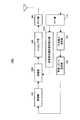
図11に示すように基地局400は、電力測定部410と、アダプティブFFR処理部420とを有する。 As illustrated in FIG. 11, the
電力測定部410は、干渉レポート信号が重畳される所定の無線リソースにおける電力を測定する。電力測定部410は、共通無線リソースを構成するn本のキャリアのそれぞれに対応するキャリア電力測定部411−1〜nを有している。同図には、n=3の場合が示されている。キャリア電力測定部411は、対応するキャリアの電力を測定し、測定結果をアダプティブFFR処理部420に送出する。 The
アダプティブFFR処理部420は、干渉レベル判定部421と、モード選択部422とを有する。アダプティブFFR処理部420は、所定の期間に電力測定部410から受け取る電力測定結果が所定のしきい値より大きいキャリアと対応する送信モードに切り換える。具体的には、干渉レベル判定部421が、各キャリア電力測定部411から受け取る電力測定結果と干渉有無判断しきい値とを比較し、干渉有無判断しきい値より大きい電力測定結果が得られたキャリアを示すキャリア識別情報をモード選択部422に出力する。そして、モード選択部422は、干渉レベル判定部421から受け取るキャリア識別情報と対応する送信モードを選択する。 The adaptive
次に、上記構成を有する無線端末300及び基地局400から構成される無線通信システムについて説明する。なおここでも、無線通信システムは、図4に示すような状況であるものとして説明する。 Next, a radio communication system including
実施の形態1と同様に、NB−Aは、自セル及び隣接セルに存在するUEから、共通無線リソースを用いて送信された干渉レポートを受信する。ただし、実施の形態2では、共通無線リソースは複数のキャリアを含んでいる。 Similar to
UEは、その複数のキャリアの中から、下り回線の受信品質(例えば、受信SIR)に応じたキャリアを選択し、選択されたキャリアを用いて干渉レポートを送信する。なお、本実施の形態では、最も受信品質が良好な場合に選択される送信モードに対応するキャリアは用意されていない。 The UE selects a carrier according to downlink reception quality (for example, reception SIR) from among the plurality of carriers, and transmits an interference report using the selected carrier. In the present embodiment, no carrier corresponding to the transmission mode selected when the reception quality is the best is not prepared.
このようにしてUEから送信される干渉レポートは、例えば、NB−Aにおいて、図12に示すような電力分布で受信される。 The interference report transmitted from the UE in this way is received with a power distribution as shown in FIG. 12, for example, in NB-A.
NB−Aは、干渉有無判断しきい値よりもキャリアの電力測定値が大きいキャリアに応じて、送信モードを変更する。この送信モードの変更は、以下の方法により行うことができる。 NB-A changes the transmission mode according to the carrier whose carrier power measurement value is larger than the interference presence / absence determination threshold value. The transmission mode can be changed by the following method.
第1の方法としては、干渉有無判断しきい値よりも電力測定値が大きいキャリアのうち下り受信品質が最も低いキャリアに対応するモードに変更するものである。こうすることで、自セル及び隣接セルに存在するすべてのUEにおける干渉レベルを低減することができる。 As a first method, the mode is changed to the mode corresponding to the carrier having the lowest downlink reception quality among the carriers having the power measurement value larger than the interference presence / absence determination threshold value. By doing so, it is possible to reduce the interference level in all UEs existing in the own cell and adjacent cells.
第2の方法としては、干渉有無判断しきい値よりも電力測定値が大きいキャリアのうち最も電力測定値が大きいキャリアに対応するモードに変更するものである。こうすることで、自セル及び隣接セルにおいて、最も多くのUEが干渉レポートを送信する際に用いたキャリアに対応するモードに変更することができる。 As a second method, the mode is changed to the mode corresponding to the carrier having the largest power measurement value among the carriers having the power measurement value larger than the interference presence / absence determination threshold. By carrying out like this, it can change to the mode corresponding to the carrier used when most UEs transmit an interference report in an own cell and an adjacent cell.
なお、いずれの方法であっても、最も受信品質が良好な場合に選択される送信モード(図12では、モード1)は、これ以外の送信モードに対応するキャリアに関する電力測定値がいずれも干渉有無判断しきい値よりも小さいときに選択される。 In any method, the transmission mode (
すなわち、NB−Aで図12のような電力分布が観測される場合、第1の方法ではモード4が選択され、第2の方法ではモード2が選択される。また、NB−Aで図13のような電力分布が観測される場合、第1の方法及び第2の方法のいずれもモード3が選択される。 That is, when a power distribution as shown in FIG. 12 is observed in NB-A, mode 4 is selected in the first method, and
このように本実施の形態によれば、無線端末300では、キャリア選択部330が受信SIRに応じたキャリアを共通無線リソースから選択し、マッピング部340が選択されたキャリアに干渉レポート信号をマッピングする。 Thus, according to the present embodiment, in
こうすることにより、干渉レポート信号の受信側は干渉レポート信号の重畳されているキャリアを特定することで、その干渉レポートを送信した無線端末300の干渉レベルを把握することができる。また、干渉レポート信号の受信側である基地局は、自セル及び隣接セルに存在する無線端末300から干渉レポート信号を受信するので、自セル及び隣接セルにおける干渉レベル分布を把握することができる。 By doing so, the reception side of the interference report signal can identify the carrier on which the interference report signal is superimposed, thereby grasping the interference level of the
また、基地局400では、アダプティブFFR処理部420が、同じ期間で受信された複数の干渉レポートの送信に用いられているキャリアと対応する送信モードに切り換える。 In
こうすることにより、段階的に送信モードを変更する実施の形態1と異なり、干渉レポートの重畳されているキャリアと対応する送信モードに直接的に切り換えるので、適切な送信モードに高速に切り換えることができる。 By doing so, unlike the first embodiment in which the transmission mode is changed step by step, the transmission mode is directly switched to the transmission mode corresponding to the carrier on which the interference report is superimposed. it can.
(実施の形態3)
実施の形態1では、共通無線リソースの測定電力値とモード変更判断しきい値との比較結果に基づいて送信モードを段階的に変更している。これに対して、本実施の形態では、送信モードと電力値の範囲とを予め対応づけておき、測定電力値の収まる電力値の範囲と対応する送信モードに直接的に変更する。(Embodiment 3)
In the first embodiment, the transmission mode is changed stepwise based on the comparison result between the measured power value of the common radio resource and the mode change determination threshold value. On the other hand, in the present embodiment, the transmission mode and the power value range are associated in advance, and the transmission mode is directly changed to the transmission mode corresponding to the power value range in which the measured power value falls.
図14に示すように本実施の形態の基地局500は、アダプティブFFR処理部510を有する。 As shown in FIG. 14,
アダプティブFFR処理部510は、電力測定部220にて測定された、共通無線リソースの測定電力値に対応する送信モードに変更する。 Adaptive
アダプティブFFR処理部510は、各隣接送信モード間の境界であり、モード変更判断に利用されるモード変更判断しきい値を予め保持している。アダプティブFFR処理部510は、共通無線リソースの測定電力値が挟まれる2つのモード変更判断しきい値を特定し、この2つのモード変更判断しきい値で規定される範囲に対応する送信モードを選択する。アダプティブFFR処理部510は、現在の送信モードから、この選択された送信モードに、送信モードを直接変更する。 Adaptive
アダプティブFFR処理部510は、例えば、図15に示すようにモード変更判断しきい値Th1〜3を保持している。そして、図15のような測定電力値が得られた場合、モード変更判断しきい値Th2及びTh3により規定されるモード3に送信モードが変更される。 The adaptive
このように本実施の形態によれば、基地局500では、アダプティブFFR処理部510が、送信モードと電力値の範囲とを予め対応づけておき、合成受信電力値の収まる電力値範囲と対応する送信モードに直接的に切り換える。 As described above, according to the present embodiment, in
こうすることにより、段階的に送信モードを変更する実施の形態1と異なり、合成受信電力値の収まる電力値範囲と対応する送信モードに直接的に切り換えるので、適切な送信モードに高速に切り換えることができる。 In this way, unlike the first embodiment in which the transmission mode is changed step by step, the transmission mode is directly switched to the transmission mode corresponding to the power value range in which the combined reception power value is accommodated. Can do.
(実施の形態4)
本実施の形態では、実施の形態3の基地局の構成に、受信電力を時間平均する時間平均部を設ける。(Embodiment 4)
In the present embodiment, a time averaging unit that averages received power over time is provided in the configuration of the base station of the third embodiment.
図16に示すように本実施の形態の基地局600は、FFT部210と、電力測定部220との間に、時間平均部610を有する。 As shown in FIG. 16,
時間平均部610は、電力測定部220への入力信号の電力を時間方向で平均化する。 The time averaging unit 610 averages the power of the input signal to the
ここで、厳密には、各UEから送られた干渉レポートの受信電力レベルは、それぞれ異なる。さらに、干渉レポート信号が互いに弱めあったり強め合ったりするので、共通無線リソースの電力は変動しやすい(レイリー分布)。そのため、その変動が激しい場合には、適切に送信モード(リユースファクタ)を選択できない可能性がある。 Here, strictly speaking, the reception power levels of the interference reports transmitted from the UEs are different. Furthermore, since the interference report signals weaken or strengthen each other, the power of the common radio resource is likely to fluctuate (Rayleigh distribution). Therefore, when the fluctuation is severe, there is a possibility that the transmission mode (reuse factor) cannot be selected appropriately.
そこで、本実施の形態では、時間平均部610を設け、共通無線リソースの電力変動のリユースファクタ選択に対する影響がなくなるように、電力測定部220への入力信号の電力を時間方向で平均化する。こうすることで、信号電力の分散が小さくなるので、共通無線リソースにおける電力変動を少なくでき、この結果、適切にリユースファクタを選択できる。 Therefore, in the present embodiment, a time averaging unit 610 is provided, and the power of the input signal to the
(実施の形態5)
実施の形態1乃至4では、自セルに存在する無線端末から送信される干渉レポートも、モード変更の判断材料として扱っている。すなわち、送信モードは、自セルのUEが受ける干渉の影響も考慮された上で、決定されている。(Embodiment 5)
In
より適切に送信モードを変更するためには、自セルが隣接セルに与える干渉のみに基づいて送信モードを決定することが好ましい。そこで、本実施の形態では、自セルに存在する無線端末からの干渉レポートがモード変更の判断材料から除かれる、送信モード変更方法が示される。特に、この方法が実施の形態3に適用された場合を例にとり説明する。 In order to change the transmission mode more appropriately, it is preferable to determine the transmission mode based only on the interference that the own cell gives to the neighboring cells. Therefore, in the present embodiment, a transmission mode change method is shown in which interference reports from wireless terminals existing in the own cell are excluded from the material for determining the mode change. In particular, the case where this method is applied to the third embodiment will be described as an example.
図17に示すように本実施の形態の無線端末700は、送信停止タイミング信号検出部710と、タイミング調整部720とを有する。 As shown in FIG. 17,
送信停止タイミング信号検出部710は、FFT部110を介して受け取る受信信号に含まれる送信停止タイミング信号を検出する。送信停止タイミング信号検出部710は、無線端末700の位置するセルの基地局から送信された送信停止タイミング信号を検出する。 The transmission stop timing
タイミング調整部720は、送信停止タイミング信号検出部710にて検出される送信停止タイミング信号に基づいて、干渉レポートの送信タイミングを調整する。 The
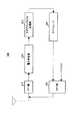
図18に示すように本実施の形態の基地局800は、送信停止タイミング信号生成部810を有する。 As shown in FIG. 18,
送信停止タイミング信号生成部810は、自セルの無線端末700が干渉レポートの送信を、隣接セルの干渉レポート送信期間に行わないように制御するための送信停止タイミング信号を生成する。この送信停止タイミング信号は、自セルに存在する無線端末700に送信される。 The transmission stop timing
次に上記構成を有する無線端末700及び基地局800から構成される無線通信システムについて説明する。なおここでも、無線通信システムは、図4に示すような状況であるものとして説明する。 Next, a radio communication system including
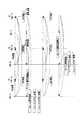
図19に示すように、NB−A,B,Cは、RSとデータとを、UEに向けてそれぞれ送信する。セルA,B,Cに存在する各UEは、SIRを測定する。 As shown in FIG. 19, NB-A, B, and C transmit RS and data toward UE, respectively. Each UE present in cells A, B, and C measures SIR.
そしてまずNB−Aにおいて、隣接セルに存在するUEからの干渉レポートに基づく送信モードの変更処理が行われる。 First, in NB-A, a transmission mode change process based on an interference report from a UE existing in a neighboring cell is performed.
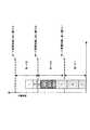
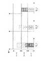
具体的には、セルB,Cに存在するUEは、測定したSIRに基づいて干渉レポート信号を生成し、この干渉レポート信号を共通無線リソースを用いて送信する。このとき、NB−Aは、送信停止タイミング信号を送信することにより、セルAに存在するUEの干渉レポートの送信を停止させている。すなわち、図20Aに示すように、セルB及びCに存在するUE−D〜I(同図では、円で囲まれている)が干渉レポート信号を送信するタイミングで、セルAに存在するUE−A〜Cは、干渉レポート信号の送信を停止している。こうすることにより、NB−Aは、隣接セルから送信された干渉レポートのみを受信することができる(図21左図参照)。 Specifically, UEs existing in cells B and C generate an interference report signal based on the measured SIR, and transmit the interference report signal using a common radio resource. At this time, the NB-A stops transmitting the interference report of the UE existing in the cell A by transmitting a transmission stop timing signal. That is, as shown in FIG. 20A, UE-D to I (encircled in FIG. 20) existing in the cells B and C transmit UEs that are present in the cell A at the timing of transmitting the interference report signal. A to C stop transmitting the interference report signal. By doing so, the NB-A can receive only the interference report transmitted from the neighboring cell (see the left diagram in FIG. 21).
そして、NB−Aは、隣接セルから送信された干渉レポートに基づいて、リユースファクタを決定し、このリユースファクタに変更する。 And NB-A determines a reuse factor based on the interference report transmitted from the adjacent cell, and changes to this reuse factor.
そして、NB−Aは、リユースファクタの変更後、下り回線の割当を変更した上で、RSとデータとをUEに向けて送信する。このとき、NB−B,Cも、UEに向けてRSとデータとを送信する。そして、セルA,B,Cに存在する各UEは、SIRを測定する。 Then, after changing the reuse factor, the NB-A changes the downlink allocation and then transmits RS and data to the UE. At this time, NB-B and C also transmit RS and data toward the UE. And each UE which exists in cell A, B, C measures SIR.
そして次にNB−Bにおいて、隣接セルに存在するUEからの干渉レポートに基づく送信モードの変更処理が行われる。 Then, in NB-B, transmission mode change processing is performed based on interference reports from UEs existing in neighboring cells.
今回はNB−Bが送信モードの変更処理を行う順番なので、セルBに存在するUEの干渉レポートの送信が停止されている。すなわち、図20Bに示すように、セルA及びCに存在するUE−A〜C,E〜I(同図では、円で囲まれている)が干渉レポート信号を送信するタイミングで、セルBに存在するUE−D〜Fは、干渉レポート信号の送信を停止している。こうすることにより、NB−Bは、隣接セルから送信された干渉レポートのみを受信することができる(図21中央図参照)。 Since this time is the order in which the NB-B performs the transmission mode change process, transmission of the interference report of the UE existing in the cell B is stopped. That is, as shown in FIG. 20B, UE-A to C and E to I (encircled in the figure) existing in cells A and C transmit to the cell B at the timing of transmitting the interference report signal. The existing UE-D to F stop transmission of the interference report signal. By doing so, the NB-B can receive only the interference report transmitted from the neighboring cell (see the central diagram in FIG. 21).
同様にして、NB−Cも、隣接セルから送信された干渉レポートのみを受信することができる(図21右図参照)。以上のように本実施の形態の無線通信システムでは、近接する複数の基地局が順番に自セル内の干渉レポートの送信を停止させることにより、各基地局は自セルの停止区間に隣接セルの干渉レポートのみを取得することができる。 Similarly, the NB-C can receive only the interference report transmitted from the neighboring cell (see the right diagram in FIG. 21). As described above, in the radio communication system according to the present embodiment, a plurality of neighboring base stations sequentially stop the transmission of interference reports in the own cell, so that each base station Only interference reports can be obtained.
このように本実施の形態によれば、基地局800では、送信停止タイミング信号生成部810が、自セルにある無線端末の干渉レポートの送信を前記隣接セルにある複数の無線端末が干渉レポートを送信する送信区間に停止するために、送信停止タイミング信号を送信する。 As described above, according to the present embodiment, in
こうすることにより、基地局800は自セルの干渉レポートを除いた隣接セルからの干渉レポートにのみ基づいて送信モードを選択できるので、より適切に送信モードを変更することができる。 By doing so,
(実施の形態6)
実施の形態5では、UEの干渉レポートの送信を、隣接するセルの間で順次停止することにより、隣接セルから送信される干渉レポートにのみ基づいて送信モードを変更する。本実施の形態では、無線端末の干渉レポートの送信が停止されているセルの基地局から、下り回線で送信される信号に基づいて、その基地局との間の下り回線のパスロスを無線端末が測定する。そして、その基地局の隣接セルに存在する無線端末は、そのパスロスに基づいて送信電力を制御した上で、干渉レポートを送信する。(Embodiment 6)
In Embodiment 5, the transmission mode is changed based on only the interference report transmitted from the neighboring cell by sequentially stopping the transmission of the UE interference report between the neighboring cells. In the present embodiment, a wireless terminal determines a downlink path loss with a base station based on a signal transmitted from a base station of a cell in which transmission of an interference report of the wireless terminal is stopped. taking measurement. And the radio | wireless terminal which exists in the adjacent cell of the base station transmits an interference report, controlling transmission power based on the path loss.
図22に示すように本実施の形態の無線端末900は、パスロス測定部910と、送信電力設定部920と、増幅部930とを有する。 As shown in FIG. 22,
パスロス測定部910は、自セルの隣接セルのそれぞれに対応するm個のパスロス測定部911を有する。同図には、m=2の場合が示されている。すなわち、パスロス測定部910は、自セルに対応するパスロス測定部911も含めて3つのパスロス測定部911−1〜3を有している。パスロス測定部911−1〜3は、それぞれが対応するセルで干渉レポートの送信が停止されている期間にそのセルから下り回線で送信される信号を用いて、そのセルの基地局と自装置との間の下り回線のパスロスを測定する。 The path
送信電力設定部920は、自装置が存在するセルの隣接セルに対応する測定パスロス値に基づいて、送信電力を制御する。送信電力設定部920は、自装置が存在するセルの隣接セルに対応する測定パスロス値に基づいて、増幅部930の増幅率を設定する。 The transmission
増幅部930は、送信電力設定部920により設定された増幅率で、干渉レポートを増幅する。 The
ここで上述のように、各UEから送られた干渉レポートの受信電力レベルは、それぞれ異なる。さらに、干渉レポート信号が互いに弱めあったり強め合ったりするので、共通無線リソースの電力は変動しやすい(レイリー分布)。そのため、その変動が激しい場合には、適切にリユースファクタを選択できない可能性がある。 Here, as described above, the reception power levels of the interference reports transmitted from the UEs are different. Furthermore, since the interference report signals weaken or strengthen each other, the power of the common radio resource is likely to fluctuate (Rayleigh distribution). Therefore, when the fluctuation is severe, there is a possibility that the reuse factor cannot be selected appropriately.
そこで、本実施の形態では、無線端末900は、自装置が存在するセルの隣接セルに対応する測定パスロス値に基づいて、送信電力を制御する。こうすることにより、基地局における干渉レポート信号の平均受信電力が一定となり、共通無線リソースにおける干渉レポート信号の合成受信電力の変動が少なくなる。これは、等利得合成の送信ダイバーシチにおいて平均受信電力が一定であれば、送信アンテナ数が多くなるほど分散が減ることに基づいている。以上のことから、基地局において、適切にリユースファクタを選択することが可能となる。 Therefore, in the present embodiment,
(実施の形態7)
本実施の形態では、実施の形態5と同様に、自セルに存在する無線端末からの干渉レポートがモード変更の判断材料から除かれる、送信モード変更方法が示される。具体的には、セルごとに異なるキャリアを用いて干渉レポートが送信される。こうすることで、隣接セルから送信された干渉レポートにのみ基づいて、送信モードを変更することができる。(Embodiment 7)
In the present embodiment, as in the fifth embodiment, a transmission mode change method is shown in which interference reports from radio terminals existing in the own cell are excluded from the material for determining the mode change. Specifically, the interference report is transmitted using a different carrier for each cell. In this way, the transmission mode can be changed based only on the interference report transmitted from the neighboring cell.
図23に示すように本実施の形態の無線端末1000は、キャリア通知信号検出部1010と、マッピング部1020とを有する。 As shown in FIG. 23,
キャリア通知信号検出部1010は、FFT部110を介して受け取る受信信号に含まれるキャリア通知信号を検出する。この検出されるキャリア通知信号は、自装置が存在するセルの基地局から送信された信号であり、共通無線リソースを構成する複数のキャリアのうち、そのセルに存在する無線端末1000が干渉レポートの送信に利用するキャリアを示している。 Carrier notification
マッピング部1020は、キャリア通信信号検出部1010にて検出されたキャリア通知信号が示すキャリアに、干渉レポート信号をマッピングする。
図24に示すように本実施の形態の基地局1100は、アダプティブFFR処理部1110と、キャリア通知信号生成部1120とを有する。 As shown in FIG. 24,
アダプティブFFR処理部1110は、共通無線リソースを構成する複数のキャリアのうち、隣接セルに対応するキャリアにおける測定電力値をすべて加算する。アダプティブFFR処理部1110は、その加算結果に基づいて、送信モードを変更する。 Adaptive
キャリア通知信号生成部1120は、共通無線リソースを構成する複数のキャリアのうち、基地局1100のカバーするセルに存在する無線端末1000が利用すべきキャリアを示すキャリア通知信号を生成する。 The carrier notification
図25には、無線通信システムが図4に示すような状況である場合に、NB−Aにおいて観測される電力分布の一例が示されている。干渉レポートの送信には、セルAではキャリア1が用いられ、セルB及びセルCではそれぞれキャリア2及びキャリア3が用いられる。よって、NB−Aは、キャリア2及びキャリア3にて観測される合成受信電力を加算した加算電力値に基づいて、送信モードを変更する。 FIG. 25 shows an example of the power distribution observed in NB-A when the wireless communication system is in the situation shown in FIG. For transmission of the interference report,
こうして、自セルが隣接セルに与える干渉のみに基づいて送信モードを決定するので、より適切な送信モードの変更を行うことができる。 In this way, since the transmission mode is determined based only on the interference that the own cell gives to the adjacent cells, it is possible to change the transmission mode more appropriately.
このように本実施の形態によれば、基地局1100では、アダプティブFFR処理部1110が、隣接セルと対応するキャリアにおける干渉レポートの受信電力が合成された合成受信電力に基づいて、送信モードを切り換える。また、干渉レポートの送信に利用されるキャリアは、隣接セルごとに異なっている。 As described above, according to the present embodiment, in
こうすることにより、基地局1100は自セルの干渉レポートを除いた隣接セルからの干渉レポートにのみ基づいて送信モードを変更できるので、より適切に送信モードを変更することができる。 By doing so, the
(実施の形態8)
本実施の形態では、実施の形態5と同様に、自セルに存在する無線端末からの干渉レポートがモード変更の判断材料から除かれる、送信モード変更方法が示される。具体的には、無線端末は、自身が存在するセルの基地局に対して送信電力が小さい方向(ヌル方向)が向くように、アンテナ指向性を制御して干渉レポートを送信する。こうすることで、隣接セルから送信された干渉レポートにのみ基づいて、送信モードを変更することができる。(Embodiment 8)
In the present embodiment, as in the fifth embodiment, a transmission mode change method is shown in which interference reports from radio terminals existing in the own cell are excluded from the material for determining the mode change. Specifically, the wireless terminal transmits the interference report by controlling the antenna directivity so that the direction in which the transmission power is small (null direction) is directed to the base station of the cell in which the wireless terminal is present. In this way, the transmission mode can be changed based only on the interference report transmitted from the neighboring cell.
図26に示すように本実施の形態の無線端末1200は、指向性形成計算部1210と、指向性制御部1220とを有する。 As shown in FIG. 26,
指向性形成計算部1210は、自装置が存在するセルの基地局に対してヌル方向が向くような、指向性重み係数を算出する。指向性形成計算部1210は、例えば、自装置が存在するセルの基地局から送信された信号の受信品質が最も良くなるような受信時の指向性重み計数を特定する。この特定された受信時の指向性重み計数は、自装置が存在するセルの基地局に対して指向性が形成され、その基地局とは反対側にヌル方向が向いているときの重み計数である。指向性形成計算部1210は、この特定された受信時の指向性重み計数に基づいて、自装置が存在するセルの基地局に対してヌル方向が向くような、指向性重み係数を算出する。 The directivity
指向性制御部1220は、指向性形成計算部1210にて算出された指向性重み計数を用いてアンテナ指向性を制御しつつ、IFFT部160を介して受け取る干渉レポート信号を送信する。 The
無線通信システムの各セルに存在する各無線端末1200が、自装置が存在するセルの基地局に対してヌル方向が向くようにアンテナ指向性を制御することにより、無線通信システムは、図27に示すような状況となる。 Each
そして無線通信システムの基地局では、図28に示すように自セルの無線端末1200から送信される干渉レポートが除かれた合成受信電力が観測される。本実施の形態では、実施の形態3で説明した基地局500と同様の構成を持つ基地局を用いることができる。 Then, in the base station of the wireless communication system, the combined received power from which the interference report transmitted from the
このように本実施の形態によれば、無線端末1200では、指向性形成計算部1210が、自装置が存在するセルの基地局に対してヌル方向が向くような、指向性重み係数を算出し、指向性制御部1220が、指向性形成計算部1210にて算出された指向性重み計数を用いてアンテナ指向性を制御しつつ干渉レポート信号を送信する。 As described above, according to the present embodiment, in
こうすることにより、基地局は自セルの干渉レポートを除いた隣接セルからの干渉レポートにのみ基づいて送信モードを選択できるので、より適切に送信モードを変更することができる。 By doing so, the base station can select the transmission mode based only on the interference report from the neighboring cell excluding the interference report of its own cell, and can change the transmission mode more appropriately.
(実施の形態9)
本実施の形態では、実施の形態5と同様に、自セルに存在する無線端末からの干渉レポートがモード変更の判断材料から除かれる、送信モード変更方法が示される。具体的には、セルごとに異なる拡散コードを用いて拡散された干渉レポートが送信される。こうすることで、隣接セルから送信された干渉レポートにのみ基づいて、送信モードを変更することができる。(Embodiment 9)
In the present embodiment, as in the fifth embodiment, a transmission mode change method is shown in which interference reports from radio terminals existing in the own cell are excluded from the material for determining the mode change. Specifically, an interference report spread using a different spreading code for each cell is transmitted. In this way, the transmission mode can be changed based only on the interference report transmitted from the neighboring cell.
図29に示すように本実施の形態の無線端末1300は、拡散系列通知信号検出部1310と、拡散部1320とを有する。 As shown in FIG. 29,
拡散系列通知信号検出部1310は、FFT部110を介して受け取る受信信号に含まれる拡散系列通知信号を検出する。この検出される拡散系列通知信号は、自装置が存在するセルの基地局から送信された信号であり、そのセル内に存在する無線端末1000が利用する拡散系列を示している。 Spreading sequence notification
拡散部1320は、拡散系列通知信号検出部1310にて検出された拡散系列を用いて、干渉レポート信号を拡散する。 Spreading
図30に示すように本実施の形態の基地局1400は、逆拡散部1410と、合成部1420と、拡散系列通知信号生成部1430とを有する。 As shown in FIG. 30,
逆拡散部1410は、隣接セルのそれぞれに対応するm個の逆拡散部1411を有している。m個の隣接セルには、それぞれ異なる拡散系列が割り当てられている。逆拡散部1411は、対応する隣接セルに割り当てられている拡散系列を用いて、FFT部210を介して受け取る受信信号を逆拡散する。 The
合成部1420は、各逆拡散部1411で逆拡散された後の信号を電力合成し、合成後の信号を電力測定部220に出力する。電力測定部220では、この合成後の信号の電力が測定される。 Combining
拡散系列通知信号生成部1430は、自セルに割り当てられている拡散系列を示す拡散系列通知信号を生成する。この拡散系列通知信号は、IFFT部250を介して送信される。 Spreading sequence notification
なお、各実施の形態において、共通無線リソースとして、OFDM通信に利用されるサブキャリアのうち直流成分からなるキャリア(DCキャリア)を用いることができる。こうして通常データ伝送に使用されないDCキャリアを有効に利用することができる。 In each embodiment, a carrier (DC carrier) composed of a direct current component among subcarriers used for OFDM communication can be used as a common radio resource. Thus, a DC carrier that is not normally used for data transmission can be used effectively.
2007年9月26日出願の特願2007−249896の日本出願に含まれる明細書、図面および要約書の開示内容は、すべて本願に援用される。 The disclosure of the specification, drawings, and abstract included in the Japanese application of Japanese Patent Application No. 2007-249896, filed on Sep. 26, 2007 is incorporated herein by reference.
本発明の無線基地局装置及び送信制御方法は、セル間干渉が改善されるまでの時間を短縮してシステムスループットを向上するものとして有用である。No line base station apparatus置及 beauty transmission control methodof the present invention is useful for improving the system throughput by shortening the time until inter-cell interference is improved.
Claims (9)
Translated fromJapanese前記複数の干渉レポートの受信電力分布に基づいて、前記自セルの下り回線におけるアダプティブFFR処理を制御するアダプティブFFR制御手段と、
を具備する無線基地局装置。Using a plurality of carriers selected from a plurality of carriers based on reception quality of a downlink at each of a plurality of wireless terminals existing in a plurality of adjacent cells adjacent to the own cell covered by the own device, Receiving means for receiving a plurality of interference reports transmitted from thewireless terminal;
Adaptive FFR control means for controlling adaptive FFR processing in the downlink of the own cell based on the received power distribution of the plurality of interference reports;
A radio base station apparatus comprising:
前記複数の干渉レポートの受信電力分布に基づいて、前記自セルの下り回線におけるアダプティブFFR処理を制御するアダプティブFFR制御手段と、
を具備する無線基地局装置。Using a plurality of carriers selected based on each of the plurality of adjacent cells from a plurality of carriers associated with the respective adjacent cells adjacent to the local cell in which its own devicecovers, multiplewireless terminals Receiving means for receiving a plurality of interference reports transmitted from
Adaptive FFR control means for controlling adaptive FFR processing in the downlink of the own cell based on the received power distribution of the plurality of interference reports;
A radio base station apparatus comprising:
請求項1または2に記載の無線基地局装置。The adaptive FFR control means switches a transmission mode based on a received power distribution of combined received power obtained by combining received power of the plurality of interference reports.
The radio base station apparatus according to claim 1 or 2.
請求項1または2に記載の無線基地局装置。The adaptive FFR control means stores a correspondence relationship between each transmission mode and a power range corresponding to each transmission mode, and corresponds to the power range in which a combined reception power obtained by combining the reception powers of the plurality of interference reports is contained. Select the transmission mode to be used,
The radio base station apparatus according to claim 1 or 2.
請求項4に記載の無線基地局装置。Averaged means for averaging the combined received power over time,
The radio base station apparatus according to claim 4.
前記アダプティブFFR制御手段は、前記共通送信区間で前記複数の無線端末から送信された干渉レポートの受信電力が合成された合成受信電力の受信電力分布に基づいて、送信モードを切り換える、
請求項1または2に記載の無線基地局装置。Stop signal for transmitting an interference report stop signal for stopping transmission of an interference report of a wireless terminal existing in the own cell in a common transmission section in which a plurality of wireless terminals existing in the plurality of neighboring cells transmit an interference report Comprising a transmission means;
The adaptive FFR control means switches a transmission mode based on a received power distribution of combined received power obtained by combining received power of interference reports transmitted from the plurality of wireless terminals in the common transmission section.
The radio base station apparatus according to claim 1 or 2.
受信した前記複数の干渉レポートを前記複数の隣接セルのそれぞれの拡散コードで逆拡散し、逆拡散後の信号を出力する逆拡散手段と、
前記逆拡散後の信号を前記複数の隣接セルについて電力合成する電力合成手段と、
を具備し、
前記アダプティブFFR制御手段は、前記電力合成手段にて電力合成された信号の電力値に基づいて、送信モードを切り換える、
請求項1または2に記載の無線基地局装置。The radio base station apparatus receives a plurality of interference reports spread with different spreading sequences in each of the plurality of neighboring cells,
Despreading means for despreading the received interference reports with respective spreading codes of the plurality of neighboring cells and outputting a signal after despreading;
Power combining means for combining the power of the despread signals for the plurality of neighboring cells;
Comprising
The adaptive FFR control means switches the transmission mode based on the power value of the signal that has been subjected to power combining by the power combining means.
The radio base station apparatus according to claim 1 or 2.
前記複数の干渉レポートの受信電力分布に基づいて、前記自セルにおけるアダプティブFFR処理を制御する制御ステップと、
を具備する送信制御方法。Using the carrier selected from a plurality of carriers based on downlink reception quality at each of aplurality of wireless terminals existing in aplurality of adjacent cells adjacent to the own cell covered by the base station apparatus, A receiving step of receiving a plurality of interference reports transmitted from thewireless terminal;
A control step of controlling adaptive FFR processing in the own cell based on the received power distribution of the plurality of interference reports;
A transmission control method comprising:
前記複数の干渉レポートの受信電力分布に基づいて、前記自セルにおけるアダプティブFFR処理を制御する制御ステップと、
を具備する送信制御方法。Using a plurality of carriers selected based on each of the plurality of adjacent cells from a plurality of carriers associated with the respective neighboring cell adjacent to the local cell of the base station apparatuscovers, themultipleradio A receiving step for receiving a plurality of interference reports transmitted from the terminal;
A control step of controlling adaptive FFR processing in the own cell based on the received power distribution of the plurality of interference reports;
A transmission control method comprising:
Priority Applications (1)
| Application Number | Priority Date | Filing Date | Title |
|---|---|---|---|
| JP2009534178AJP5121838B2 (en) | 2007-09-26 | 2008-09-25 | Radio base station apparatus and transmission control method |
Applications Claiming Priority (4)
| Application Number | Priority Date | Filing Date | Title |
|---|---|---|---|
| JP2007249896 | 2007-09-26 | ||
| JP2007249896 | 2007-09-26 | ||
| JP2009534178AJP5121838B2 (en) | 2007-09-26 | 2008-09-25 | Radio base station apparatus and transmission control method |
| PCT/JP2008/002656WO2009041040A1 (en) | 2007-09-26 | 2008-09-25 | Radio communication system, radio base station device, and transmission control method |
Publications (2)
| Publication Number | Publication Date |
|---|---|
| JPWO2009041040A1 JPWO2009041040A1 (en) | 2011-01-20 |
| JP5121838B2true JP5121838B2 (en) | 2013-01-16 |
Family
ID=40510945
Family Applications (1)
| Application Number | Title | Priority Date | Filing Date |
|---|---|---|---|
| JP2009534178AExpired - Fee RelatedJP5121838B2 (en) | 2007-09-26 | 2008-09-25 | Radio base station apparatus and transmission control method |
Country Status (5)
| Country | Link |
|---|---|
| US (1) | US9226301B2 (en) |
| EP (1) | EP2194741A1 (en) |
| JP (1) | JP5121838B2 (en) |
| CN (1) | CN101810021A (en) |
| WO (1) | WO2009041040A1 (en) |
Families Citing this family (21)
| Publication number | Priority date | Publication date | Assignee | Title |
|---|---|---|---|---|
| US8718658B2 (en)* | 2009-06-25 | 2014-05-06 | Samsung Electronics Co., Ltd. | Communication system for distributedly managing interference using feedback message |
| US8428629B2 (en)* | 2010-03-31 | 2013-04-23 | Qualcomm Incorporated | Methods and apparatus for determining a communications mode and/or using a determined communications mode |
| CN102238718B (en)* | 2010-04-30 | 2015-09-16 | 中兴通讯股份有限公司 | Transmitting diversity implementation method in a kind of multi-user system and equipment |
| US9585024B2 (en) | 2010-07-27 | 2017-02-28 | Huawei Technologies Co., Ltd. | System and method for self-organized inter-cell interference coordination |
| EP2630831A4 (en)* | 2010-10-20 | 2016-10-26 | Nokia Technologies Oy | Interference-aware scheduling with broadcast/multicast signaling |
| WO2012093289A1 (en)* | 2011-01-04 | 2012-07-12 | Nokia Corporation | Frame structure and signaling arrangement for interference aware scheduling |
| JP5769190B2 (en)* | 2011-03-14 | 2015-08-26 | 国立研究開発法人情報通信研究機構 | Self-coexistence mechanism when merging cells in wireless networks |
| WO2012103850A2 (en)* | 2012-04-11 | 2012-08-09 | 华为技术有限公司 | Method and device for configuring transmission mode |
| US10085154B2 (en) | 2012-10-17 | 2018-09-25 | Huawei Technologies Co., Ltd. | System and method for dynamic inter-cell interference coordination |
| KR102089437B1 (en)* | 2013-03-07 | 2020-04-16 | 삼성전자 주식회사 | Method and apparatus for controlling interference in wireless communication system |
| JP6497726B2 (en)* | 2014-03-14 | 2019-04-10 | シャープ株式会社 | Terminal, base station, communication system, communication method, and program |
| CN105554885A (en)* | 2015-03-17 | 2016-05-04 | 西安电子科技大学 | Adaptive-frequency-spectrum-reuse-based femtocell interference reduction method |
| CN107710802B (en) | 2015-06-26 | 2022-02-18 | 瑞典爱立信有限公司 | Method used in control node and serving radio node and related equipment |
| US10085206B2 (en)* | 2016-03-08 | 2018-09-25 | Wipro Limited | Methods and systems for optimization of cell selection in TD-SCDMA networks |
| BR112020001375A2 (en) | 2017-08-01 | 2020-08-11 | Telefonaktiebolaget Lm Ericsson (Publ) | methods of selecting a bundle and monitoring a bundle, base station, user equipment, and computer program product. |
| CN109086225B (en)* | 2018-07-23 | 2021-06-04 | 广州慧睿思通信息科技有限公司 | Data processing method for removing direct current carrier and outputting segmented shift by FFTC (frequency filter time division multiple access) output based on PKTDMA (public key time division multiple access) |
| US12041589B2 (en)* | 2020-08-17 | 2024-07-16 | Charter Communications Operating, Llc | Methods and apparatus for spectrum utilization coordination between wireline backhaul and wireless systems |
| US11582055B2 (en) | 2020-08-18 | 2023-02-14 | Charter Communications Operating, Llc | Methods and apparatus for wireless device attachment in a managed network architecture |
| US11563593B2 (en) | 2020-08-19 | 2023-01-24 | Charter Communications Operating, Llc | Methods and apparatus for coordination between wireline backhaul and wireless systems |
| US11844057B2 (en) | 2020-09-09 | 2023-12-12 | Charter Communications Operating, Llc | Methods and apparatus for wireless data traffic management in wireline backhaul systems |
| EP4552399A1 (en)* | 2022-07-08 | 2025-05-14 | Cisco Technology, Inc. | Coordinating puncturing in wireless access points |
Citations (2)
| Publication number | Priority date | Publication date | Assignee | Title |
|---|---|---|---|---|
| WO2006043588A1 (en)* | 2004-10-19 | 2006-04-27 | Sharp Kabushiki Kaisha | Base station device, wireless communication system, and wireless transmission method |
| WO2006087797A1 (en)* | 2005-02-18 | 2006-08-24 | Fujitsu Limited | Base station and interference reduction method in the base station |
Family Cites Families (4)
| Publication number | Priority date | Publication date | Assignee | Title |
|---|---|---|---|---|
| WO2005096523A1 (en)* | 2004-03-30 | 2005-10-13 | Matsushita Electric Industrial Co., Ltd. | Base station device, mobile station device, and data channel allocation method |
| EP1999982B1 (en)* | 2006-03-20 | 2018-08-29 | BlackBerry Limited | Method&system for fractional frequency reuse in a wireless communication network |
| CN102595616B (en)* | 2006-03-21 | 2017-04-26 | 艾利森电话股份有限公司 | Measurement-assisted dynamic frequency-reuse in cellular telecommuncations networks |
| EP1887709B1 (en)* | 2006-08-10 | 2009-12-23 | Alcatel Lucent | Method and apparatus for uplink transmission power control based on interference from neighbouring cells |
- 2008
- 2008-09-25JPJP2009534178Apatent/JP5121838B2/ennot_activeExpired - Fee Related
- 2008-09-25WOPCT/JP2008/002656patent/WO2009041040A1/enactiveApplication Filing
- 2008-09-25USUS12/678,099patent/US9226301B2/ennot_activeExpired - Fee Related
- 2008-09-25CNCN200880108748Apatent/CN101810021A/enactivePending
- 2008-09-25EPEP08834426Apatent/EP2194741A1/ennot_activeWithdrawn
Patent Citations (2)
| Publication number | Priority date | Publication date | Assignee | Title |
|---|---|---|---|---|
| WO2006043588A1 (en)* | 2004-10-19 | 2006-04-27 | Sharp Kabushiki Kaisha | Base station device, wireless communication system, and wireless transmission method |
| WO2006087797A1 (en)* | 2005-02-18 | 2006-08-24 | Fujitsu Limited | Base station and interference reduction method in the base station |
Non-Patent Citations (2)
| Title |
|---|
| CSNC201110033167; Nortel: 'Further Discussion on Adaptive Fractional Frequency Reuse' 3GPP TSG-RAN WG1#48b R1-071449 , 20070330, インターネット<URL:http://www.3gpp.org/ftp/tsg_ra* |
| JPN6012028199; Nortel: 'Further Discussion on Adaptive Fractional Frequency Reuse' 3GPP TSG-RAN WG1#48b R1-071449 , 20070330, インターネット<URL:http://www.3gpp.org/ftp/tsg_ra* |
Also Published As
| Publication number | Publication date |
|---|---|
| US20100222003A1 (en) | 2010-09-02 |
| EP2194741A1 (en) | 2010-06-09 |
| WO2009041040A1 (en) | 2009-04-02 |
| CN101810021A (en) | 2010-08-18 |
| JPWO2009041040A1 (en) | 2011-01-20 |
| US9226301B2 (en) | 2015-12-29 |
Similar Documents
| Publication | Publication Date | Title |
|---|---|---|
| JP5121838B2 (en) | Radio base station apparatus and transmission control method | |
| JP6983669B2 (en) | Downlink interference measurement method and equipment in orthogonal frequency division multiple access mobile communication system | |
| KR101587005B1 (en) | Apparatus and method for transmitting control information for interference mitigation in multiple antenna system | |
| EP2074763B1 (en) | A method and apparatus for fast other sector interference (osi) adjustment | |
| US9924524B2 (en) | Base station apparatus and communication control method | |
| EP2533444B1 (en) | Radio communication device and radio communication method | |
| EP2642781B1 (en) | Wireless communication system and wireless communication method | |
| JP5689124B2 (en) | Method and apparatus for uplink multi-carrier transmission diversity | |
| US20110085448A1 (en) | Wireless communication system, wireless base station apparatus, and wireless communication method | |
| JP5103357B2 (en) | Mobile terminal apparatus and radio base station apparatus | |
| KR20090106504A (en) | Base station apparatus, user apparatus and method used in mobile communication system | |
| US20110273997A1 (en) | Radio communication system, scheduling method, radio base station device, and radio terminal | |
| EP3340678B1 (en) | Wireless communication system and wireless communication method | |
| CN110267341A (en) | Power is controlled in unauthorized band | |
| US9572170B2 (en) | Method and device for applying adaptive link in communication system | |
| KR20160046697A (en) | Apparatus and method for traffic load balancing using inter-site carrier aggregation | |
| KR20140057120A (en) | Apparatus and method for interference measurement in a communication system | |
| US20100254326A1 (en) | Base station apparatus, user apparatus and communication control method | |
| CN107660327A (en) | Method and apparatus for determining channel condition information | |
| US8983485B2 (en) | Base station apparatus, mobile terminal apparatus and scheduling method | |
| US20150124720A1 (en) | Radio communication system, radio base station, and communication control method | |
| US20110261782A1 (en) | Radio communication system, radio base station, and threshold setting method | |
| US20160204919A1 (en) | Method and Controlling Node for Controlling Radio Communication in a Cellular Network | |
| KR20090077821A (en) | Methods and apparatus for determining, communicating, and using information that can be used for interference control purposes | |
| Ghimire et al. | Heuristic thresholds for busy burst signalling in a decentralised coordinated multipoint network |
Legal Events
| Date | Code | Title | Description |
|---|---|---|---|
| A621 | Written request for application examination | Free format text:JAPANESE INTERMEDIATE CODE: A621 Effective date:20110404 | |
| A131 | Notification of reasons for refusal | Free format text:JAPANESE INTERMEDIATE CODE: A131 Effective date:20120605 | |
| A521 | Request for written amendment filed | Free format text:JAPANESE INTERMEDIATE CODE: A523 Effective date:20120723 | |
| A131 | Notification of reasons for refusal | Free format text:JAPANESE INTERMEDIATE CODE: A131 Effective date:20120814 | |
| A521 | Request for written amendment filed | Free format text:JAPANESE INTERMEDIATE CODE: A523 Effective date:20120903 | |
| TRDD | Decision of grant or rejection written | ||
| A01 | Written decision to grant a patent or to grant a registration (utility model) | Free format text:JAPANESE INTERMEDIATE CODE: A01 Effective date:20121002 | |
| A01 | Written decision to grant a patent or to grant a registration (utility model) | Free format text:JAPANESE INTERMEDIATE CODE: A01 | |
| A61 | First payment of annual fees (during grant procedure) | Free format text:JAPANESE INTERMEDIATE CODE: A61 Effective date:20121023 | |
| FPAY | Renewal fee payment (event date is renewal date of database) | Free format text:PAYMENT UNTIL: 20151102 Year of fee payment:3 | |
| R150 | Certificate of patent or registration of utility model | Ref document number:5121838 Country of ref document:JP Free format text:JAPANESE INTERMEDIATE CODE: R150 Free format text:JAPANESE INTERMEDIATE CODE: R150 | |
| S111 | Request for change of ownership or part of ownership | Free format text:JAPANESE INTERMEDIATE CODE: R313113 | |
| R350 | Written notification of registration of transfer | Free format text:JAPANESE INTERMEDIATE CODE: R350 | |
| LAPS | Cancellation because of no payment of annual fees |