JP5117877B2 - Lighting equipment for passenger conveyors - Google Patents
Lighting equipment for passenger conveyorsDownload PDFInfo
- Publication number
- JP5117877B2 JP5117877B2JP2008025318AJP2008025318AJP5117877B2JP 5117877 B2JP5117877 B2JP 5117877B2JP 2008025318 AJP2008025318 AJP 2008025318AJP 2008025318 AJP2008025318 AJP 2008025318AJP 5117877 B2JP5117877 B2JP 5117877B2
- Authority
- JP
- Japan
- Prior art keywords
- plate
- passenger conveyor
- unit
- led
- tread
- Prior art date
- Legal status (The legal status is an assumption and is not a legal conclusion. Google has not performed a legal analysis and makes no representation as to the accuracy of the status listed.)
- Active
Links
Images


Landscapes
- Escalators And Moving Walkways (AREA)
Description
Translated fromJapanese本発明は、エスカレータや動く歩道等の乗客コンベアに備えられ、乗降部付近を照明するLEDを有する乗客コンベアの照明装置に関する。 The present invention relates to a lighting device for a passenger conveyor that is provided on a passenger conveyor such as an escalator or a moving sidewalk, and that has an LED that illuminates the vicinity of a boarding / alighting section.
従来、乗客コンベアでは、乗客が乗降する乗降部の近傍の、踏面と乗降部のそれぞれの両脇に位置するスカートに、開口部を設け、この開口部から乗客の注意を喚起する照明を照光するようにした照明装置が知られている。 Conventionally, in a passenger conveyor, an opening is provided in a skirt located on both sides of a tread surface and a boarding / alighting part in the vicinity of a boarding / alighting part where passengers get on / off, and illumination for illuminating the passengers' attention is emitted from this opening. Such a lighting device is known.
この照明装置は、蛍光灯から成るものであった。しかし、蛍光灯は電極フィラメントに高圧の交流を印加し、多量の熱電子を放出することによって光を発するようになっているため、消費電力が比較的大きくなる。また、電極フィラメントの消耗により蛍光灯が点灯しなくなるため、寿命が比較的短い。これに伴って、蛍光灯の交換を頻繁に行なうことが必要になり、このような交換作業は、作業員の負担を招いていた。さらに蛍光灯は、内部に水銀やアルゴンガスが封入されており、蛍光灯の寿命等により蛍光灯を廃棄する際、破砕した蛍光灯のガラス片には水銀が付着している。このため、それらのガラス片を産業廃棄物としてそのまま地中に埋めると、土壌を汚染してしまうことになる。 This illuminating device consisted of a fluorescent lamp. However, since the fluorescent lamp emits light by applying a high-voltage alternating current to the electrode filament and emitting a large amount of thermoelectrons, the power consumption becomes relatively large. In addition, the life of the fluorescent lamp is relatively short because the fluorescent lamp is not lit due to consumption of the electrode filament. Along with this, it is necessary to frequently exchange fluorescent lamps, and such exchange work has caused a burden on workers. Further, the fluorescent lamp is filled with mercury or argon gas, and when the fluorescent lamp is discarded due to the life of the fluorescent lamp or the like, mercury adheres to the glass piece of the crushed fluorescent lamp. For this reason, if those glass pieces are buried in the ground as industrial waste, the soil is contaminated.
このような問題を解決しようとして、特許文献1に示される乗客コンベアの照明装置が提案されている。この従来の照明装置は、通電によりそれぞれ発光する複数個のLED体を備えたLED照明灯であり、このLED照明灯は、細長の剛性材から成り、複数個のLED体が上面側の長手方向に沿って所定間隔で配設されるプリント基板と、このプリント基板を収納し、透光性及び保形性を有する細長管と、プリント基板の下面側に配設される全波整流ダイオード、及び複数個の電流制限抵抗を含む電気部品と、細長管の両端に取り付けられ、プリント基板を細長管内に固定する絶縁材から成る一対のブッシングと、これらのブッシングの外周のそれぞれに装着される一対の口金具と、これらの口金具にそれぞれ設けられる一対の電極ピンと、これらの電極ピンとプリント基板との電気的接続を行なう接続体などを備えた構成になっている。
しかしながら、前述した特許文献1に開示される従来技術では、LED体は細長管内に設置されているが、細長管自体の防護はされておらず、上部の隙間等から雨水などが浸入する虞があり、防水性に問題がある。また、LEDは熱に弱く、自ら発する熱により寿命を縮めてしまうため放熱対策が実施されるべきであるが、特許文献1に開示される従来技術では、前述の蛍光灯を設置する場合と同じ設置方法で設置している。すなわち、LED照明灯から成る特許文献1に開示される従来技術は、LEDをより長寿命、高輝度で活用するために必要な放熱対策については、考慮がなされていなかった。 However, in the prior art disclosed in
本発明は、前述した従来技術における実状からなされたもので、その目的は、LEDを備えたものにおいて、優れた防水性と放熱性を確保することができる乗客コンベアの照明装置を提供することにある。 The present invention was made from the actual situation in the above-described prior art, and an object of the present invention is to provide an illumination device for a passenger conveyor that can ensure excellent waterproofness and heat dissipation in an LED. is there.
前記目的を達成するために、本発明に係る乗客コンベアの照明装置は、乗客を運搬可能な踏面と、この踏面の進行方向に沿って配置される床と、この床と前記踏面との境界に配置される乗降部と、前記踏面及び前記乗降部それぞれの両脇に配置されるスカートと、前記床と所定の距離に維持され、前記スカートに設けられた開口部と、この開口部を覆うように配置され、光を透過させる遮蔽板とを有する乗客コンベアに備えられ、前記スカートの反踏面側の前記開口部位置よりも上方の位置に配置され、放熱性の高い素材で水平面に対して傾斜した下部延設部を有するL字形のプレートと、前記下部延設部の下側に当接するように固定したLED照明部と、前記下部延設部の下側に固定され、前記LED照明部を光らせる駆動部とを備え、前記LED照明部と前記駆動部は、水平面に対して傾斜した前記下部延設部の傾斜上方側に前記LED照明部を、傾斜下方側に前記駆動部を固定したことを特徴としている。In order to achieve the above object, a lighting device for a passenger conveyor according to the present invention includes a tread that can carry passengers, a floor that is arranged along the traveling direction of the tread, and a boundary between the floor and the tread. A boarding / alighting part, a skirt arranged on both sides of the tread and the boarding / alighting part, an opening maintained at a predetermined distance from the floor and covering the opening. arranged, provided in the passenger conveyor having a shielding plate for transmitting light, are disposed in a position above the said opening position of the anti-tread side of theskirt,inclined relative to the horizontal plane at a highrelease thermophilic material a plateof L-shaped having a bottom extending portion obtained by the LED lighting portion which is fixed to be in contact with a lower side of thelower extension portion is fixed to the underside of thelower extension portion, the LED lighting unit and a drive unit which illuminatethe front The driver and the LED lighting unit is characterized inthat the LED lighting unit in the inclined upper side of the lower extension portion that is inclined with respect to the horizontal plane, and the drive unit is fixed to the inclined lower side.
このように構成した本発明は、上部の隙間等から浸入した雨水等がLED照明部に接触しないように、これらの雨水等を水平面に対して傾斜したプレートによって排出させることができ、また、プレートとの当接を介して、LED照明部で生じた熱をプレートによって放熱させることができ、LED照明部を備えたものにあって、優れた防水性と放熱性を確保することができる。 In the present invention configured as described above, the rainwater or the like that has entered from the upper gap or the like can be discharged by a plate that is inclined with respect to the horizontal plane so that the rainwater or the like that does not come into contact with the LED illuminating unit can be discharged. The heat generated in the LED illumination unit can be radiated by the plate through the contact with the LED illumination unit, and the LED illumination unit can be provided with excellent waterproofness and heat dissipation.
また、本発明に係る乗客コンベアの照明装置は、前記発明において、前記LED照明部の反開口部側を形成する背面に、放熱板を備えたことを特徴としている。 Moreover, the lighting device for a passenger conveyor according to the present invention is characterized in that, in the above invention, a heat sink is provided on the back surface forming the side opposite to the opening of the LED lighting unit.
また、本発明に係る乗客コンベアの照明装置は、前記発明において、前記LED照明部と前記駆動部とが固定される前記プレートの部分に複数の穴を設け、前記プレートの上方位置に、水平面に対して傾斜した放熱性の高い素材から成る別のプレートを備えたことを特徴としている。 In the passenger conveyor lighting device according to the present invention, in the invention described above, a plurality of holes are provided in a portion of the plate to which the LED lighting unit and the driving unit are fixed, and a horizontal plane is provided above the plate. It is characterized by having another plate made of highly heat-dissipating material that is inclined with respect to it.
また、本発明に係る乗客コンベアの照明装置は、前記発明において、前記別のプレートは、水平面に対して傾斜した下部延設部を有し、前記プレートの全体を覆う形状寸法に設定されたL字形のプレートから成ることを特徴としている。 Further, in the lighting device for a passenger conveyor according to the present invention, in the invention, the another plate has a lower extending portion inclined with respect to a horizontal plane, and is set to a shape dimension covering the whole of the plate. It is characterized by comprising a letter-shaped plate.
本発明によれば、放熱性の高い素材で水平面に対して傾斜した下部延設部を有するL字形のプレートと、下部延設部の下側に当接するように固定したLED照明部と、下部延設部の下側に固定され、LED照明部を光らせる駆動部とを備え、LED照明部と駆動部は、水平面に対して傾斜した下部延設部の傾斜上方側にLED照明部を、傾斜下方側に駆動部を固定したことから、上部の隙間等から浸入した雨水等を傾斜したプレートの下部延設部によって排出させることができ、また、LED照明部で生じた熱をプレートによって放熱させることができる。すなわち、LED照明部を備えたものにあって、優れた防水性と放熱性を確保することができ、これによりLED照明部の長期間にわたる高輝度の維持と長寿命化を実現させることができる。これに伴って、LED照明部の交換の頻度を少なくすることができ、このLED照明部の交換作業を行なう保守員の労力を従来に比べて軽減させることができる。According to the presentinvention, a plateof L-shaped having a lower extension portion that is inclined relative to the horizontal plane at a highrelease heat material, a LED lighting unit fixed to be in contact with a lower side of thelower extensionportion,the lower portion The LED lighting unit and the driving unit are fixed to the lower side of the extending portion and illuminate the LED lighting unit. The LED lighting unit and the driving unit are inclined to the upper side of the lower extending portion inclined with respect to the horizontal plane. Since the drive unit is fixed on the lower side, rainwater or the like that has entered from the upper gap can be discharged bythe lower extending portion of the inclined plate, and the heat generated in the LED illumination unit is radiated by the plate. be able to. That is, in the thing provided with the LED illumination part, the outstanding waterproofness and heat dissipation can be ensured, and by this, maintenance of the high brightness over a long period of time and long life of the LED illumination part can be realized. . Along with this, the frequency of replacement of the LED illumination unit can be reduced, and the labor of maintenance personnel performing the replacement operation of the LED illumination unit can be reduced as compared with the conventional case.
以下、本発明の乗客コンベアの照明装置に関する実施形態を図に基づいて説明する。 DESCRIPTION OF EMBODIMENTS Hereinafter, embodiments relating to a passenger conveyor lighting device of the present invention will be described with reference to the drawings.
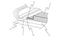
図1は本発明に係る照明装置の第1実施形態が備えられる乗客コンベアの乗降部を示す斜視図である。 FIG. 1 is a perspective view showing a boarding / alighting portion of a passenger conveyor provided with a first embodiment of a lighting device according to the present invention.
本発明に係る照明装置の第1実施形態が備えられる乗客コンベアは、図1に示すように、乗客を運搬可能な踏面1と、この踏面1の進行方向に沿って配置される床2と、この床2と踏面1との境界に配置される乗降部3と、踏面1及び乗降部3それぞれの両脇に配置されるスカート4と、床2と所定の距離に維持され、スカート4に設けられた開口部5と、この開口部5を例えば反踏面側から覆うように配置され、光を透過させる半透明な遮蔽板6とを備えている。 As shown in FIG. 1, a passenger conveyor provided with the first embodiment of the lighting device according to the present invention includes a
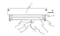
図2は図1のX矢視図であって、説明を容易にするためにスカートを省略して描いた図、図3は図2のY矢視図であって、説明を明確にするためにスカートを加えて描いた図である。 2 is a view taken in the direction of the arrow X in FIG. 1 and is drawn with the skirt omitted for ease of explanation. FIG. 3 is a view taken in the direction of the arrow Y in FIG. It is the figure drawn by adding a skirt to.
本発明に係る照明装置の第1実施形態は、これらの図2,3に示すように、スカート4の反踏面側の開口部5位置よりも上方の位置に配置され、例えば水平面に対して傾斜した下部延設部7Aを有し、放熱性の高い素材から成るL字形のプレート7と、このプレート7の下部延設部7Aの下側に当接するように固定したLED照明部8と、プレート7の下部延設部7Aの下側に固定され、LED照明部8を光らせる駆動部9とを備えている。また、LED照明部8と駆動部9を接続する第1配線コード10と、電源回路部11と駆動部9を接続する第2配線コード12とを備えている。図3に示すように、LED照明部8と駆動部9は、水平面に対して傾斜した下部延設部7Aの傾斜上方側にLED照明部8を、下方側に駆動部9を固定してある。As shown in FIGS. 2 and 3, the first embodiment of the lighting device according to the present invention is disposed at a position above the position of the
開口部5は、LED照明部8から発せられた光を乗降部3の方向に不足なく通し、乗客の足元を照らすことができる。また、遮蔽板6は、開口部5を完全に覆うように配置され、乗降部3の方向から塵埃等の異物が侵入してLED照明部8や駆動部9に付着することを防ぐとともに、半透明から成る材質で形成されていることによりLED照明部8から発せられた光を、乗降部3の方向に不足なく透過させることができる。 The
プレート7は、LED照明部8の上側を完全に覆い、上方の隙間等から浸入した雨水等、及び塵埃等の異物がLED照明部8に付着することを阻止する。また、L字形のプレート7の折り曲げ角度θ1は、90°よりも僅かに大きい鈍角となっている。 The
なお、LED照明部8の放熱は、LED照明部8の長期間にわたる高輝度の維持と長寿命化にあたって極めて重要な役割を果たしている。一般に、LEDは他のどのような発光デバイスよりも発熱する上、LED自身が熱に弱いデバイスであるため、積極的な放熱対策を行なわない状態での使用では、輝度の減少や4万時間といわれる寿命の短命化や、破損を招くことになる。LEDデバイスからの赤外線輻射による空気中への直接の放熱はほとんどなく、LEDが直接接触している基板と、基板が接触している部材への伝熱に依存する。したがって、本実施形態に備えられるプレート7の高い放熱性は、LED照明部8の長期間にわたる高輝度の維持と長寿命化を実現させるものである。 The heat radiation of the
このように構成した第1実施形態によれば、上部の隙間等から浸入した雨水等がLED照明部8に接触しないように、これらの雨水等を水平面に対して傾斜したプレート7の下部延設部7Aによって排出させることができる。また、プレート7の下部延設部7Aとの当接を介して、LED照明部8で生じた熱をプレート7によって放熱させることができる。すなわち、LED照明部8を備えたものにあって、優れた防水性と放熱性を確保することができ、これによりLED照明部8の長期間にわたる高輝度の維持と長寿命化を実現させることができる。これに伴って、LED照明部8の交換の頻度を少なくすることができ、この交換作業を行なう保守員の労力を軽減させることができる。 According to the first embodiment configured as described above, the lower portion of the
また、プレート7は、水平面に対して傾斜した下部延設部7Aを有する簡単な形状であることから、実用的であるとともに、製作コストを抑えることに貢献する。 Moreover, since the
図4は本発明の第2実施形態を示す図で、第1実施形態を示す図3に対応させて描いた図である。 FIG. 4 is a view showing a second embodiment of the present invention, and is a drawing corresponding to FIG. 3 showing the first embodiment.
この図4に示す第2実施形態は、前述した第1実施形態の構成に加えて、LED照明部8の反開口部5側を形成する背面に、放熱板、すなわち例えば平板から成る別のプレート13を当接するように設けた構成にしてある。 In addition to the configuration of the first embodiment described above, the second embodiment shown in FIG. 4 is a heat sink, that is, another plate made of, for example, a flat plate on the back surface forming the side opposite to the
プレート13は、プレート7と同様に放熱性の高い素材から成り、LED照明部8が発した熱が伝導されて効率的な放熱を可能とするものである。前述のように、LED照明部8は、このLED照明部8に接する部材への伝熱に依存するため、この第2実施形態によれば、放熱性の高いプレート7と別のプレート13の双方における放熱によって、第1実施形態におけるよりもさらに優れた放熱性を確保することができる。なお、別のプレート13は簡単な形状であることから、実用的であるとともに、製作コストを抑えることに貢献する。 The plate 13 is made of a material having a high heat dissipation property like the
図5は本発明の第3実施形態を示す図で、第1実施形態を示す図3に対応させて描いた図である。 FIG. 5 is a diagram showing a third embodiment of the present invention, and is a diagram corresponding to FIG. 3 showing the first embodiment.
この図5に示す第3実施形態は、前述した第1実施形態の構成に加えて、LED照明部8と駆動部9とが固定されるプレート7の部分、すなわち下部延設部7Aに複数の穴、例えば円穴14を設け、プレート7の上方位置に、例えば水平面に対して傾斜した下部延設部15Aを有し、放熱性の高い素材から成るL字形の別のプレート15を備えた構成にしてある。この別のプレート15の下部延設部15Aは、プレート7の上側の全体を覆うことが可能な形状寸法に設定されている。 In addition to the configuration of the first embodiment described above, the third embodiment shown in FIG. 5 includes a plurality of portions on the
このように構成した第3実施形態によれば、プレート7は、複数設けられた円穴14を介して、さらに効率の良い放熱を実現できる。しかしながら、上方から雨水等が侵入した場合、その雨水等が円穴14から入り込み、LED照明部8や駆動部9に接触する虞がある。このことを考慮して、L字形の別のプレート15の折り曲げ角度θ2は、90°よりも僅かに大きい鈍角に形成し、これによって下部延設部15Aを水平面に対して傾斜させ、下部延設部15Aに付着した雨水等を、この下部延設部15Aを介して排出させるようにしてある。この第3実施形態にあっても、高い放熱性と防水性を確保することができる。また、別のプレート15も前述したプレート7と同様に、水平面に対して傾斜した下部延設部15Aを有する簡単な形状であることから、実用的であるとともに、製作コストを抑えることに貢献する。 According to 3rd Embodiment comprised in this way, the
1 踏面
2 床
3 乗降部
4 スカート
5 開口部
6 遮蔽板
7 プレート
7A 下部延設部
8 LED照明部
9 駆動部
13 別のプレート(放熱板)
14 円穴
15 別のプレート
15A 下部延設部DESCRIPTION OF
14
Claims (4)
Translated fromJapanese前記スカートの反踏面側の前記開口部位置よりも上方の位置に配置され、放熱性の高い素材で水平面に対して傾斜した下部延設部を有するL字形のプレートと、前記下部延設部の下側に当接するように固定したLED照明部と、前記下部延設部の下側に固定され、前記LED照明部を光らせる駆動部とを備え、
前記LED照明部と前記駆動部は、水平面に対して傾斜した前記下部延設部の傾斜上方側に前記LED照明部を、傾斜下方側に前記駆動部を固定したことを特徴とする乗客コンベアの照明装置。A tread that can carry passengers, a floor that is arranged along the direction of travel of the tread, a boarding / alighting section that is arranged at the boundary between the floor and the tread, and both sides of each of the tread and the boarding / alighting part Provided at a passenger conveyor having a skirt, an opening provided in the skirt, which is maintained at a predetermined distance from the floor, and a shielding plate which is disposed so as to cover the opening and transmits light.
Said than the opening position of the anti-tread side of the skirt are located above thepositionof the L-shaped having a lower extension portion that is inclined relative to the horizontal plane at a highrelease thermophilic material plate and of thelower extension portion An LED illuminating unit fixed so as to abut on the lower side, and a driving unit fixed on the lower side of thelower extending portion and causing the LED illuminating unit to shine,
The LED lighting unit and the driving unit are fixed to the upper side of the lower extending portion that is inclined with respect to a horizontal plane, and the driving unit is fixed to the lower side of the inclination . Lighting device.
前記LED照明部の反開口部側を形成する背面に、放熱板を備えたことを特徴とする乗客コンベアの照明装置。In the passenger conveyor lighting device accordingto claim 1,
An illuminating device for a passenger conveyor, comprising a heat radiating plate on a back surface forming the side opposite to the opening of the LED illuminating unit .
前記LED照明部と前記駆動部とが固定される前記プレートの部分に複数の穴を設け、前記プレートの上方位置に、水平面に対して傾斜した放熱性の高い素材から成る別のプレートを備えたことを特徴とする乗客コンベアの照明装置。In the passenger conveyor lighting device accordingto claim 1,
Aplurality of holes are provided in a portion of the plate to which the LED illumination unitand the driving unit are fixed, and another plate made of a highly heat-dissipating material that is inclined with respect to a horizontal plane is provided above the plate . A lighting device for a passenger conveyor.
前記別のプレートは、水平面に対して傾斜した下部延設部を有し、前記プレートの全体を覆う形状寸法に設定されたL字形のプレートから成ることを特徴とする乗客コンベアの照明装置。In the illumination device of the passenger conveyor accordingto claim3 ,
The saidanother plate has the lower extension part inclined with respect to the horizontal surface, and consists of an L-shaped plate set to the shape dimension which covers the said whole plate, The illuminating device of the passenger conveyor characterized by the above-mentioned.
Priority Applications (1)
| Application Number | Priority Date | Filing Date | Title |
|---|---|---|---|
| JP2008025318AJP5117877B2 (en) | 2008-02-05 | 2008-02-05 | Lighting equipment for passenger conveyors |
Applications Claiming Priority (1)
| Application Number | Priority Date | Filing Date | Title |
|---|---|---|---|
| JP2008025318AJP5117877B2 (en) | 2008-02-05 | 2008-02-05 | Lighting equipment for passenger conveyors |
Publications (2)
| Publication Number | Publication Date |
|---|---|
| JP2009184772A JP2009184772A (en) | 2009-08-20 |
| JP5117877B2true JP5117877B2 (en) | 2013-01-16 |
Family
ID=41068433
Family Applications (1)
| Application Number | Title | Priority Date | Filing Date |
|---|---|---|---|
| JP2008025318AActiveJP5117877B2 (en) | 2008-02-05 | 2008-02-05 | Lighting equipment for passenger conveyors |
Country Status (1)
| Country | Link |
|---|---|
| JP (1) | JP5117877B2 (en) |
Families Citing this family (1)
| Publication number | Priority date | Publication date | Assignee | Title |
|---|---|---|---|---|
| CN106494986A (en)* | 2016-11-09 | 2017-03-15 | 日立电梯(广州)自动扶梯有限公司 | Anti-clamping device for skirt plate and escalator |
Family Cites Families (12)
| Publication number | Priority date | Publication date | Assignee | Title |
|---|---|---|---|---|
| JPH03259895A (en)* | 1990-03-09 | 1991-11-19 | Toshiba Corp | Safety device of man conveyer |
| JPH07144865A (en)* | 1993-11-19 | 1995-06-06 | Toshiba Corp | Escalator |
| JPH1050136A (en)* | 1996-05-30 | 1998-02-20 | Toshiba Lighting & Technol Corp | Lighting fixtures and lighting systems |
| JP3269387B2 (en)* | 1996-06-06 | 2002-03-25 | 三菱電機株式会社 | Lighting equipment for passenger conveyors |
| JP2000251503A (en)* | 1999-02-26 | 2000-09-14 | Yamada Shomei Kk | Lighting equipment |
| JP3814714B2 (en)* | 2000-06-21 | 2006-08-30 | 株式会社日立製作所 | Railing lighting system for passenger conveyor |
| JP2003335490A (en)* | 2002-05-17 | 2003-11-25 | Toshiba Elevator Co Ltd | Man conveyor with handrail illuminating device |
| JP2006244725A (en)* | 2005-02-28 | 2006-09-14 | Atex Co Ltd | Led lighting system |
| JP2006292221A (en)* | 2005-04-07 | 2006-10-26 | Toshiba Corp | refrigerator |
| JP2007119227A (en)* | 2005-10-31 | 2007-05-17 | Toshiba Elevator Co Ltd | Passenger conveyor |
| JP5026704B2 (en)* | 2006-01-18 | 2012-09-19 | 東芝エレベータ株式会社 | Passenger conveyor |
| JP2007317778A (en)* | 2006-05-24 | 2007-12-06 | Harison Toshiba Lighting Corp | Backlight unit |
- 2008
- 2008-02-05JPJP2008025318Apatent/JP5117877B2/enactiveActive
Also Published As
| Publication number | Publication date |
|---|---|
| JP2009184772A (en) | 2009-08-20 |
Similar Documents
| Publication | Publication Date | Title |
|---|---|---|
| TWI557363B (en) | Assembly of substrate and lighting equipment | |
| JP5442708B2 (en) | Lighting device using light emitting diode | |
| US6929382B2 (en) | Lighting fixture | |
| KR101020807B1 (en) | LED lighting | |
| US20130343045A1 (en) | LED Light Module | |
| CN101737673A (en) | Illumination device | |
| EP3040610B1 (en) | Led streetlamp | |
| US20140003049A1 (en) | Luminaire | |
| JP4277047B1 (en) | LED lamp | |
| KR20120108662A (en) | Led lamp | |
| KR20230037813A (en) | LED floor pedestrian traffic light | |
| JP5510744B2 (en) | lighting equipment | |
| KR20080104708A (en) | Lamp using LED | |
| JP5117877B2 (en) | Lighting equipment for passenger conveyors | |
| EP2644978B1 (en) | Led lighting apparatus | |
| KR20110131385A (en) | LED luminaire with cortex pad | |
| KR101096640B1 (en) | LED module light for mat | |
| JP2013143319A (en) | Lighting fixture | |
| CN102563406A (en) | Lighting fixture | |
| KR100770970B1 (en) | Body work light for emergency vehicle | |
| JP2013067449A (en) | Elevator lighting apparatus | |
| KR101590376B1 (en) | Down light | |
| CN104566031A (en) | Lamp and mounting method thereof | |
| KR20160108851A (en) | The led lighting for street light | |
| KR20130129705A (en) | Light-emitting device illumination apparatus |
Legal Events
| Date | Code | Title | Description |
|---|---|---|---|
| A621 | Written request for application examination | Free format text:JAPANESE INTERMEDIATE CODE: A621 Effective date:20100301 | |
| A977 | Report on retrieval | Free format text:JAPANESE INTERMEDIATE CODE: A971007 Effective date:20111220 | |
| A131 | Notification of reasons for refusal | Free format text:JAPANESE INTERMEDIATE CODE: A131 Effective date:20120626 | |
| A521 | Written amendment | Free format text:JAPANESE INTERMEDIATE CODE: A523 Effective date:20120814 | |
| TRDD | Decision of grant or rejection written | ||
| A01 | Written decision to grant a patent or to grant a registration (utility model) | Free format text:JAPANESE INTERMEDIATE CODE: A01 Effective date:20121009 | |
| A01 | Written decision to grant a patent or to grant a registration (utility model) | Free format text:JAPANESE INTERMEDIATE CODE: A01 | |
| A61 | First payment of annual fees (during grant procedure) | Free format text:JAPANESE INTERMEDIATE CODE: A61 Effective date:20121018 | |
| R150 | Certificate of patent or registration of utility model | Free format text:JAPANESE INTERMEDIATE CODE: R150 Ref document number:5117877 Country of ref document:JP Free format text:JAPANESE INTERMEDIATE CODE: R150 | |
| FPAY | Renewal fee payment (event date is renewal date of database) | Free format text:PAYMENT UNTIL: 20151026 Year of fee payment:3 | |
| S531 | Written request for registration of change of domicile | Free format text:JAPANESE INTERMEDIATE CODE: R313531 | |
| R350 | Written notification of registration of transfer | Free format text:JAPANESE INTERMEDIATE CODE: R350 |