JP5112270B2 - Scalp care equipment - Google Patents
Scalp care equipmentDownload PDFInfo
- Publication number
- JP5112270B2 JP5112270B2JP2008311215AJP2008311215AJP5112270B2JP 5112270 B2JP5112270 B2JP 5112270B2JP 2008311215 AJP2008311215 AJP 2008311215AJP 2008311215 AJP2008311215 AJP 2008311215AJP 5112270 B2JP5112270 B2JP 5112270B2
- Authority
- JP
- Japan
- Prior art keywords
- nozzle
- scalp care
- blower
- air
- body case
- Prior art date
- Legal status (The legal status is an assumption and is not a legal conclusion. Google has not performed a legal analysis and makes no representation as to the accuracy of the status listed.)
- Expired - Fee Related
Links
Images


Landscapes
- Cleaning And Drying Hair (AREA)
- Massaging Devices (AREA)
Description
Translated fromJapanese本発明は、送風を吹き付けることにより頭皮のマッサージを行なう頭皮ケア装置に関するものである。 The present invention relates to a scalp care device that massages the scalp by blowing air.
通常、上記のような頭皮ケア装置は、送風機を収容する本体ケースと、同本体ケースに取着されるノズルとを備えている。即ち、使用者は、ノズルの先端に形成された吹出口から吹き出される送風を頭皮に吹き付けることにより、その風圧によるマッサージ効果(血行促進とそれによる頭皮細胞及び毛根(毛母細胞)の活性化等)を得ることができる。そして、更に、例えば、特許文献1に記載の頭皮ケア装置では、ノズル先端にイボ状突起を有するローラーを突設し、同ローラーを頭皮に接触させた状態で使用することにより、併せて、当該イボ状突部の押圧によるマッサージ効果を得ることが可能となっている。
しかしながら、上記従来の構成には、その送風の吹き付け位置を移動させる際にローラーが毛髪に絡みつき切れ毛や脱毛を起こしてしまう可能性がある。また、使用時の風音や風圧は、多分に個々人の趣向に依存するものであり、ノズル先端から突設されたローラーにより規定されるその送風の吹き付け距離が、必ずしも全ての使用者に快適であるとはいえない。そのため、その風音や風圧に使用者が違和感を覚えるおそれがあり、この点において、なお改善の余地を残すものとなっていた。 However, in the above-described conventional configuration, there is a possibility that the roller entangles with the hair when moving the blowing position of the air blow and causes hair breakage or hair loss. In addition, the wind noise and pressure during use depend on the taste of the individual, and the blowing distance of the air blown by the roller protruding from the nozzle tip is not necessarily comfortable for all users. There is no such thing. Therefore, the user may feel uncomfortable with the wind noise and wind pressure, and there is still room for improvement in this respect.
本発明は、上記問題点を解決するためになされたものであって、その目的は、安全且つ快適な使用感を確保しつつ、より高いマッサージ効果を得ることのできる頭皮ケア装置を提供することにある。 The present invention has been made to solve the above-described problems, and an object of the present invention is to provide a scalp care device capable of obtaining a higher massage effect while ensuring a safe and comfortable feeling of use. It is in.
上記問題点を解決するために、請求項1に記載の発明は、送風機を収容する本体ケースと、前記本体ケースに取着されるノズルとを備え、前記ノズルの先端には、前記送風機に圧送された送風が収束されて吹き出される吹出口が形成された頭皮ケア装置において、前記ノズルを回転させる回転機構を備えるとともに、前記吹出口は、断面が全体として細長の矩形状に形成されて、前記ノズルの回転軸を基準とした非同心円形状に形成されており、前記吹出口の長手方向の中央部に、該吹出口を閉塞する閉塞部を備え、前記閉塞部により、前記吹出口が該閉塞部の両側に設けられた二つの流路に区画されること、を要旨とする。In order to solve the above-mentioned problems, the invention described in claim 1 includes a main body case that houses a blower and a nozzle that is attached to the main body case, and the tip of the nozzle is pumped to the blower. In the scalp care device in which a blowout outlet is formed by which the blown air is converged and blown out, it is provided with a rotation mechanism that rotates the nozzle, and the blowout outlet isformed in an elongated rectangular shape as a whole, The nozzle is formed in a non-concentric circular shape with reference to the rotation axis of the nozzle,and includes a closing portion that closes the outlet in the center in the longitudinal direction of the outlet. The gistis that it is dividedinto two flow paths provided on both sides of the blocking portion .
上記構成によれば、吹出口からの送風が吹き付けられる頭皮の位置は、ノズルの回転により移動する。その結果、より幅広い範囲のマッサージが可能となる。更に、ノズルの回転に伴い送風方向が変化することにより毛髪が掻き分けられる。これにより、より直接的に送風を頭皮に吹き付けることが可能になる。その結果、安全且つ快適な使用感を実現しつつ、より高いマッサージ効果を得ることができるようになる。 According to the said structure, the position of the scalp where the ventilation from a blower outlet is sprayed moves by rotation of a nozzle. As a result, a wider range of massages is possible. Further, the hair is scraped by changing the blowing direction with the rotation of the nozzle. As a result, it is possible to blow air directly onto the scalp. As a result, a higher massage effect can be obtained while realizing a safe and comfortable feeling of use.
また、上記構成によれば、局所的に風圧を上昇させて、そのマッサージ効果を高めることができる。さらに、ノズルが回転することで複数の流束が螺旋状となり、その相乗効果によって風圧が高まるポイントが生ずる。そして、その高い風圧を利用することで、より一層高いマッサージ効果を得ることができるようになる。Moreover, according tothe said structure, a wind pressure can be raised locally and the massage effect can be heightened. Furthermore, when the nozzle is rotated, a plurality of fluxes are spiraled, and a synergistic effect causes a point where the wind pressure increases. And by using the high wind pressure, an even higher massage effect can be obtained.
請求項2に記載の発明は、前記送風を加熱するヒータを備えること、を要旨とする。
上記構成によれば、その吹出口から同ヒータにより加熱された温風を吹き出させることが可能になる。その結果、そのマッサージ効果を高めるとともに、毛髪の乾燥機能をも付加することができる。The gist of the invention described in
According to the said structure, it becomes possible to blow off the warm air heated by the heater from the blower outlet. As a result, the massage effect can be enhanced and a hair drying function can be added.
請求項3に記載の発明は、前記送風の吹出方向に液体を噴霧する液体噴霧装置を備えること、を要旨とする。
請求項4に記載の発明は、帯電微粒子を発生可能な帯電微粒子発生装置を備えること、を要旨とする。The gist of the invention described in
The gist of the invention described in
上記各構成によれば、その液剤や帯電微粒子による相乗効果を期待することができる。
請求項5に記載の発明は、前記ノズルは、前記本体ケースに対して着脱可能であること、を要旨とする。According to each said structure, the synergistic effect by the liquid agent and charged fine particles can be anticipated.
The gist of the invention described in
上記構成によれば、使用者の用途や趣向にあわせて、多種多様な形状のノズルを選択して用いることが可能になる。
請求項6に記載の発明は、前記回転機構は、前記送風機のモータにより駆動されること、を要旨とする。According to the above configuration, it is possible to select and use variously shaped nozzles according to the user's application and taste.
The gist of the invention described in claim6 is that the rotating mechanism is driven by a motor of the blower.
上記構成によれば、ノズル回転用のモータを設ける構成と比較して電気的構成が簡素になる。その結果、軽量化及び低コスト化を図ることができるようになる。 According to the said structure, compared with the structure which provides the motor for nozzle rotation, an electrical structure becomes simple. As a result, weight reduction and cost reduction can be achieved.
本発明によれば、安全且つ快適な使用感を確保しつつ、より高いマッサージ効果を得ることが可能な頭皮ケア装置を提供することにある。 According to the present invention, there is provided a scalp care device capable of obtaining a higher massage effect while ensuring a safe and comfortable feeling of use.
(第1の実施形態)
以下、本発明を具体化した第1の実施形態を図面に従って説明する。
図1に示すように、本実施形態の頭皮ケア装置1は、略円筒状に形成された本体ケース2を備えており、同本体ケース2内には、モータ3によりファン4を回転駆動する送風機5が設けられている。(First embodiment)
Hereinafter, a first embodiment of the present invention will be described with reference to the drawings.
As shown in FIG. 1, the scalp care device 1 of this embodiment includes a
本実施形態では、本体ケース2の軸方向端部の一方(後方開口部6、同図中、左側の端部)には、吸入口7が形成されており、送風機5は、そのファン4の回転により、同吸入口7から本体ケース2内に吸入された空気を他方側の軸方向端部(前方開口部8、同図中、右側の端部)方向へと圧送する構成となっている。 In the present embodiment, a
尚、本実施形態では、吸入口7には、網目状の格子部9が設けられており、これにより本体ケース2内への異物の吸引を防止する構成となっている。また、本体ケース2の側面には、その軸線と略直交する方向に延設されたハンドル部10が設けられており、同ハンドル部10には、使用者により操作されるスイッチ11、モータ制御基板12、及びモータ制御基板12と外部電源とを接続する給電コード13が内蔵されている。そして、送風機5(のモータ3)は、そのスイッチ11に対する操作入力に応じたモータ制御基板12からの電力供給に基づき回転し、これにより上記の送風が行なわれる構成となっている。 In the present embodiment, the
また、本実施形態体では、本体ケース2の前方開口部8には、送風機5により圧送された送風を収束して吹き出すためのノズル15が取着されている。
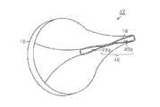
図2に示すように、本実施形態のノズル15は、本体ケース2に取着される基端部16側が当該本体ケース2の前方開口部8の形状にあわせて円筒状に形成される一方、吹出口17の形成された先端部18は扁平角筒状をなしている。即ち、本実施形態のノズル15では、その外径を軸方向に沿って徐々に絞り込むことにより基端部16側から先端部18側へと形状を徐々に変化させることで、その断面積を減少させている。つまり、その内部を通過する送風を収束して流速を高めることが可能となっている。そして、本実施形態の頭皮ケア装置1では、このように構成されたノズル15は、本体ケース2の前方開口部8に対して回転自在に取着されるとともに、その軸線Lを回転軸として同ノズル15を回転させる回転機構19が設けられている。Moreover, in this embodiment body, the
As shown in FIG. 2, the
詳述すると、図1に示すように、本実施形態では、本体ケース2の前方開口部8には、外径が小さく設定された小径部20が形成されている。具体的には、この小径部20の外径は、ノズル15の基端部16の内径よりも僅かに小さく設定されている。そして、ノズル15は、その基端部16が当該小径部20に遊嵌されることにより、本体ケース2に対し、その軸線Lを中心として回転自在に取着されている。 Specifically, as shown in FIG. 1, in the present embodiment, the
また、本実施形態では、本体ケース2の前方開口部8近傍には、上記回転機構19を収容する収容部21が形成されており、同収容部21には、モータ22と同モータ22により回転駆動されるロータ23が収容されている。 In the present embodiment, a
具体的には、モータ22は、上記送風機5の駆動源であるモータ3と同様、モータ制御基板12からの電力供給に基づき回転する。また、ロータ23は、上記のように小径部20に遊嵌されたノズル15の基端部16、詳しくは、その外周面25に当接されている。尚、本実施形態では、ロータ23は、ゴム系素材のような摩擦力の大きな弾性部材により形成されている。そして、本実施形態の回転機構19は、ハンドル部10に設けられたスイッチ11に対する操作入力による送風機5の作動、即ち送風開始とともに、その駆動源であるモータ22の回転がロータ23を介してノズル15に伝達されることにより、同ノズル15を回転させる構成となっている(図3参照)。 Specifically, the
次に、上記のように構成された頭皮ケア装置1の使用例について説明する。
使用者は、そのノズル15の先端側を頭部に向けた状態で頭皮ケア装置1のハンドル部10を把持し、同ハンドル部10に設けられたスイッチ11を操作する。そして、吹出口17から吹き出される送風を頭皮に吹き付けることにより、そのマッサージを行なうことが可能となっている。Next, the usage example of the scalp care apparatus 1 comprised as mentioned above is demonstrated.
The user grips the
尚、このような送風の吹き付けによるマッサージは、その頭皮に吹き付けられる風圧が、約25〜125kPa(キロパスカル)程度である場合に高い効果を得ることができ、更に、約50〜60kPa程度である場合にその効果が最大となる。そして、本実施形態の頭皮ケア装置1では、上記ハンドル部10に設けられたスイッチ11を操作することにより、その吹出口17から約100mm離れた送風位置において上記のような最適範囲の風圧が得られるように構成されている。つまり、本実施形態の頭皮ケア装置1は、そのノズル15をマッサージしようとする部位から約100mm程度離した位置において使用することが望ましい。In addition, such a massage by blowing air can obtain a high effect when the wind pressure blown on the scalp is about 25 to 125 kPa (kilopascal), and is further about 50 to 60 kPa. In some cases, the effect is maximized. And in the scalp care apparatus 1 of this embodiment, by operating the
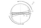
また、図2に示すように、本実施形態におけるノズル15の先端部18は扁平角筒状に形成されており、当該先端部18に形成された吹出口17もまた、その断面が細長の矩形状となっている。即ち、吹出口17は、ノズル15の回転軸(軸線L)に対して非同心円形状に形成されており、当該吹出口17からの送風が吹き付けられる頭皮の位置は、そのノズル15の回転により移動する。そして、本実施形態では、これにより、より幅広い範囲のマッサージが可能となっている。また、ノズル15の回転に伴い送風方向が変化することにより毛髪が掻き分けられ、これにより直接的に送風が頭皮に吹き付けることが可能になる。そして、本実施形態では、これにより、安全且つ快適な使用感を実現しつつ、より高いマッサージ効果を得ることが可能な構成となっている。 In addition, as shown in FIG. 2, the
尚、上記のような効果を得るためには、ノズル15の回転速度は、約60〜240rpm程度であることが望ましく、更には約100〜130rpmであることがより好ましい。そして、本実施形態では、上記ハンドル部10に設けられたスイッチ11を操作することにより、そのノズル15の回転速度をこのような最適な範囲内に制御することが可能となっている。 In order to obtain the effects as described above, the rotation speed of the
以上、本実施形態によれば、以下のような作用・効果を得ることができる。
頭皮ケア装置1は、略円筒状に形成された本体ケース2と送風機5とを備える。また、本体ケース2の前方開口部8には、送風機5により圧送された送風を収束して吹き出すノズル15が回転自在に取着されるとともに、その軸線Lを回転軸として同ノズル15を回転させる回転機構19が設けられている。そして、その先端部18に形成された吹出口17の断面は細長の矩形状に形成、即ち、そのノズル15の回転軸(軸線L)を基準とした非同心円形状に形成される。As described above, according to the present embodiment, the following operations and effects can be obtained.
The scalp care device 1 includes a
上記構成によれば、吹出口17からの送風が吹き付けられる頭皮の位置は、そのノズル15の回転に伴って移動する。その結果、より幅広い範囲のマッサージが可能となる。更に、ノズル15の回転に伴い送風方向が変化することにより毛髪が掻き分けられる。これにより、より直接的に送風を頭皮に吹き付けることが可能になる。その結果、安全且つ快適な使用感を実現しつつ、より高いマッサージ効果を得ることができるようになる。 According to the above configuration, the position of the scalp where the air blown from the
(第2の実施形態)
以下、本発明を具体化した第2の実施形態を図面に従って説明する。尚、説明の便宜上、上記第1の実施形態と同一の構成については、同一の符号を付すことにより、その説明を省略する。(Second Embodiment)
Hereinafter, a second embodiment of the present invention will be described with reference to the drawings. For convenience of explanation, the same components as those in the first embodiment are denoted by the same reference numerals, and the description thereof is omitted.
図4に示すように、本実施形態の頭皮ケア装置31では、本体ケース2は、送風機5を収容するとともに外周にハンドル部10が設けられた外筒体32と、同外筒体32の内側に同軸配置されるとともに軸受33,34により回転自在に支承された内筒体35とにより構成されている。また、本実施形態では、ノズル15は、その基端部16が内筒体35の前方開口部36(同図中、右側の軸方向端部)にスプライン嵌合されることにより、同内筒体35に対して相対回転不能に取着される。そして、本実施形態の回転機構37は、送風機5のモータ3を駆動源として、この内筒体35とノズル15とを一体に回転させる構成になっている。 As shown in FIG. 4, in the
詳述すると、本実施形態では、上記の内筒体35は外筒体32の前方開口部38(同図中、右側の軸方向端部)近傍に設けられている。また、送風機5の駆動源であるモータ3は、外筒体32の内部において同内筒体35によりも後方(同図中、左側)に配置されており、モータ軸39の先端に設けられたファン4は、同モータ軸39を延伸することにより内筒体35内に配置されている。そして、内筒体35には、そのモータ軸39の回転を内筒体35に伝達する伝達機構40が設けられている。 More specifically, in the present embodiment, the inner
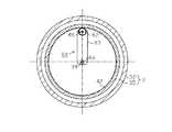
さらに詳述すると、図5に示すように、モータ軸39には、第1のサンギヤ41が設けられている。また、内筒体35の内周には、リングギヤ42が形成されるとともに、このリングギヤ42には第2のサンギヤ43が噛合されている。そして、これら第1のサンギヤ41及び第2のサンギヤ43が第3のサンギヤ44に噛合されることにより、モータ軸39と内筒体35とが駆動連結されている。 More specifically, as shown in FIG. 5, the
即ち、本実施形態では、その前方開口部36にノズル15が固定された内筒体35と、同内筒体35とモータ軸39とを駆動連結する伝達機構(上記各ギヤ(41〜44))により、回転機構37が形成されている。 That is, in this embodiment, the
また、本実施形態では、内筒体35内には、送風機5の送風を加熱するヒータ45が設けられている。尚、このヒータ45は、ハンドル部10内に収容されたヒータ制御基板46から供給される電力に応じた熱量を発生する構成となっており、作業者は、ハンドル部10に設けられたスイッチ11を操作することにより、そのヒータ45への電力供給量、即ちヒータ45の発熱を制御することが可能となっている。そして、ノズル15の先端部18(の吹出口17)からは、このヒータ45により加熱された温風が吹き出される構成となっている。 In the present embodiment, the
尚、このような温風の吹き付けによるマッサージ効果は、その頭皮に吹き付けられる際の温度が、約10〜50℃程度であることが望ましく、更に、その効果は約35〜42℃である場合に最大となる。また、毛髪を乾燥させるためのドライヤーとして用いる場合、その毛髪に吹き付けられる際の温度は、約60〜150℃程度であることが望ましく、更には、約80〜120℃であることがより好ましい。そして、本実施形態の頭皮ケア装置1では、上記ハンドル部10に設けられたスイッチ11を操作することによって、その吹出口17から約100mm離れた送風位置において上記最適な温度範囲を有する温風が得られるように構成されている。In addition, it is desirable that the temperature when the scalp is sprayed is about 10 to 50 ° C., and the effect is about 35 to 42 ° C. Maximum. Moreover, when using as a dryer for drying hair, it is desirable that the temperature at which the hair is sprayed is about 60 to 150 ° C, and more preferably about 80 to 120 ° C. And in scalp care apparatus 1 of this embodiment, the hot air which has the said optimal temperature range in the ventilation position about 100mm away from the
以上、本実施形態によれば、以下のような作用・効果を得ることができる。
(1)本体ケース2は、送風機5を収容する外筒体32と、同外筒体32の内側において回転自在に支承された内筒体35とを備えてなる。また、ノズル15は、その基端部16が内筒体35の前方開口部36にスプライン嵌合されることにより、同内筒体35に対して相対回転不能に取着される。そして、回転機構37は、送風機5のモータ3を駆動源として、この内筒体35とノズル15とを一体に回転させる。As described above, according to the present embodiment, the following operations and effects can be obtained.
(1) The
上記構成によれば、ノズル回転用のモータを設ける構成と比較して電気的構成が簡素になる。その結果、軽量化及び低コスト化を図ることができるようになる。そして、更に、ノズル15を脱落させることなく、安定的に同ノズル15を回転させることができるようになる。 According to the said structure, compared with the structure which provides the motor for nozzle rotation, an electrical structure becomes simple. As a result, weight reduction and cost reduction can be achieved. Further, the
(2)内筒体35内には、送風機5の送風を加熱するヒータ45が設けられている。これにより、ノズル15の先端部18(の吹出口17)から同ヒータ45により加熱された温風を吹き出させることが可能になる。その結果、そのマッサージ効果を高めるとともに、毛髪の乾燥機能をも付加することができる。 (2) In the
なお、上記各実施形態は以下のように変更してもよい。
・上記各実施形態では、ノズル15の先端部18に形成された吹出口17は、断面細長の矩形状をなすこととした。しかし、これに限らず、ノズル15の回転軸(軸線L)を基準とした非同心円形状であれば、その他の形状であってもよい。即ち、その形状がノズル15の回転軸を基準とした同心円形状である場合には、同ノズル15の回転によっても、その送風の吹き付け位置が移動せず、上記の効果が得られないためである。In addition, you may change each said embodiment as follows.
In each of the above embodiments, the
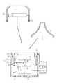
・また、図6に示すノズル47のように、その吹出口48が、複数の流路49a,49bに区画された構成であってもよい。このような構成とすれば、局所的に風圧を上昇させて、そのマッサージ効果を高めることができる。さらに、ノズル15が回転することで複数の流束が螺旋状となり、その相乗効果によって風圧が高まるポイントが生ずる。そして、その高い風圧を利用することで、より一層高いマッサージ効果を得ることができる。尚、吹出口として区画された流路の数、及びその形状は、図6に示される例に限定されないことは言うまでもない。 -Moreover, the structure by which the
・上記第2の実施形態では、本体ケース2が外筒体32の内側において回転する内筒体35を有する構成において、同内筒体35の内側に送風以外の付加機能部としてヒータ45を設ける構成とした。しかし、これに限らず、図7に示すように、第1の実施形態のように、内筒体のような構成を有せず、直接的にノズル15を回転させる構成について、ヒータ45を設ける構成としてもよい。 In the second embodiment, in the configuration in which the
・また、送風以外の付加機能部として、図8に示すように、液体を貯留可能なタンク51とその吐出部52を設けることで、その送風の吹出方向に液体を噴霧可能な液体噴霧装置53を形成し、水やスチームの他、トリートメント剤やセット剤、或いは育毛剤等の液剤を噴霧可能な構成としてもよい。これにより、その液剤噴霧との相乗効果を期待することができる。更に、このような液体噴霧装置53に代えて帯電微粒子発生装置54を設けても良く、この場合にも、同様の相乗効果が期待できる。尚、これらの付加機能部は、本体ケース2の内側に設ける構成であってもよい。そして、更には、一の装置で、ヒータ45、液体噴霧装置53、及び帯電微粒子発生装置54の少なくとも一つを含む複数の付加機能を有するものを用いる構成であってもよい。 Further, as shown in FIG. 8, as an additional function unit other than air blowing, by providing a
・本実施形態では、特に言及しなかったが、ノズル15は、本体ケース2(内筒体35)に対して着脱可能であることが望ましい。これにより、使用者の用途や趣向にあわせて、多種多様な形状のノズル15を選択して用いることが可能になる。 -Although it did not mention in this embodiment in particular, it is desirable for the
・更に、ノズル側に上記ヒータ45、液体噴霧装置53、及び帯電微粒子発生装置54のような付加機能部を設ける構成とするとよい。例えば、図9に示すように、ノズル55内にヒータ45を設ける。尚、ヒータ45への電力供給は、本体ケース2(外筒体32)及びノズル55の双方にスリップリングのような接点56,57を設けるとよい。 Further, it is preferable to provide an additional function unit such as the
このような構成とすれば、ノズル15からノズル55に換装することで、ドライヤーとしての使用が可能になる。また、ノズル15に換装し頭皮ケア装置として使用する場合には、ヒータ45がない分だけ、装置が小型になり操作性が向上する。そして、更に、送風機5からノズル15の吹出口17までの距離が短くなることで圧力損失が少なくなり、その結果、より高いマッサージ効果を得ることができるようになる。 If it is set as such a structure, the use as a dryer will be attained by replacing the
・また、単なるドライヤーとして用いる場合には、その換装したノズルが回転しない構成としてもよい。
・上記第1の実施形態におけるロータはギヤの噛み合いによりノズル15を回転させる構成であってもよい。また、反対に、上記第2の実施形態における伝達機構40は、ギヤの噛み合いによるものでなく、ゴム系素材等を用いた摩擦力による駆動力伝達によるものであってもよい。そして、更には、このような物理的な接触によるものではなく、磁気誘導等、電磁的に回転伝達を行うものであってもよい。-Moreover, when using as a mere dryer, it is good also as a structure where the replaced nozzle does not rotate.
-The rotor in the said 1st Embodiment may be the structure which rotates the
・上記各実施形態では、特に言及しなかったが、ノズル15(55)の回転方向は、一方向であっても、往復動作を行なうものであってもよい。
・上記第2の実施形態においては、3つのサンギヤ(41,43,34)、及び内筒体35の内周に形成されたリングギヤ42により、モータ軸39の回転を内筒体35に伝達する伝達機構40を構成することとした(図4及び図5参照)。しかし、これに限らず、例えば、4以上のギヤを用いて伝達機構40を構成する等としてもよい。-Although not mentioned in particular in each said embodiment, even if the rotation direction of the nozzle 15 (55) is one direction, you may perform reciprocation.
In the second embodiment, the rotation of the
更に、図10,図11に示されるように、リングギヤ42に噛合されるサンギヤ62とモータ軸39との間に減速機63を介在させることにより伝達機構60を構成してもよい。具体的には、図示しない減速機構が内蔵された減速機63の入力軸64にモータ軸39を連結し、同減速機63の出力軸65にサンギヤ62を連結すればよい。尚、上記のような伝達機構の変速比は、約1:100程度が望ましい。 Further, as shown in FIGS. 10 and 11, the
次に、以上の実施形態から把握することのできる請求項以外の技術的思想をその作用とともに記載する。
(付記1)前記ノズルは、前記本体ケースに対して着脱可能であるとともに、前記ノズルには、前記送風を加熱するヒータ、前記送風の吹出方向に液体を噴霧する液体噴霧装置、及び帯電微粒子を発生可能な帯電微粒子発生装置の少なくとも一つの機能を有する付加機能部が設けられること、を特徴とする頭皮ケア装置。Next, technical ideas other than the claims that can be grasped from the above embodiments will be described together with the operation thereof.
(Supplementary Note1) before SL nozzle, wherein together detachable from the main body casing, the nozzle, the blowing heater for heating the liquid spray device for spraying a liquid in the delivery direction of the air blowing, and the charged particles A scalp care device, characterized in that an additional function part having at least one function of a charged particle generator capable of generating a hair is provided.
上記構成によれば、そのノズルの換装により、例えば、ドライヤー専用としての使用が可能になる。また、ノズル内に付加機能部を有さない頭皮ケア装置と使用する場合には、当該付加機能部の分だけ装置が小型になり、その結果、操作性が向上する。そして、更に、送風機から吹出口までの距離が短くなることで圧力損失が少なくなる。その結果、より高いマッサージ効果を得ることができるようになる。 According to the said structure, the use only for a dryer becomes possible, for example by replacement | exchange of the nozzle. Moreover, when using with the scalp care apparatus which does not have an additional function part in a nozzle, an apparatus becomes small by the part of the said additional function part, As a result, operativity improves. And furthermore, pressure loss decreases because the distance from a blower to a blower outlet becomes short. As a result, a higher massage effect can be obtained.
(付記2)前記回転機構は、回転自在に前記本体ケースのハウジング内に支承された筒体と、該筒体に前記モータの回転を伝達する伝達機構とを備えてなり、前記ノズルは前記筒体の開口端に前記取着されること、を特徴とする頭皮ケア装置。(Supplementary Note2) before Symbol rotation mechanism includes a rotatably the main body case supporting in-cylinder body in a housing of, be provided with a transmission mechanism for transmitting the rotation of the motor to the tube body, the nozzle is the A scalp care device, wherein the scalp care device is attached to an open end of a cylindrical body.
上記構成によれば、ノズル回転用のモータを設ける構成と比較して電気的構成が簡素になる。その結果、軽量化及び低コスト化を図ることができるようになる。そして、更に、ノズルを脱落させることなく、安定的に同ノズルを回転させることができるようになる。 According to the said structure, compared with the structure which provides the motor for nozzle rotation, an electrical structure becomes simple. As a result, weight reduction and cost reduction can be achieved. Further, the nozzle can be stably rotated without dropping the nozzle.
1,31…頭皮ケア装置、2…本体ケース、3…モータ、4…ファン、5…送風機、8…前方開口部、10…ハンドル部、11…スイッチ、12…モータ制御基板、15,47,55…ノズル、16…基端部、17,48…吹出口、18…先端部、19,37…回転機構、20…小径部、22…モータ、23…ロータ、24…内周、25…外周面、32…外筒体、35…内筒体、36,38…前方開口部、39…モータ軸、40,60…伝達機構、45…ヒータ、46…ヒータ制御基板、49a,49b…流路、51…タンク、52…吐出部、53…液体噴霧装置、54…帯電微粒子発生装置、L…軸線(回転軸)。 DESCRIPTION OF
Claims (6)
Translated fromJapanese前記ノズルを回転させる回転機構を備えるとともに、
前記吹出口は、断面が全体として細長の矩形状に形成されて、前記ノズルの回転軸を基準とした非同心円形状に形成されており、
前記吹出口の長手方向の中央部に、該吹出口を閉塞する閉塞部を備え、
前記閉塞部により、前記吹出口が該閉塞部の両側に設けられた二つの流路に区画されること、
を特徴とする頭皮ケア装置。A scalp care comprising a main body case that houses a blower and a nozzle that is attached to the main body case, and at the tip of the nozzle, an air outlet is formed by which the air blown to the blower is converged and blown out. In the device
A rotation mechanism for rotating the nozzle,
The blower outlet isformed in a non-concentric circular shape with across section formed in an elongated rectangular shape as a whole, with the rotation axis of the nozzle as a reference,
A central portion in the longitudinal direction of the air outlet includes a closing portion that closes the air outlet,
By the blocking part, the outlet is divided into two flow paths provided on both sides of the blocking part,
Scalp care device characterized by.
前記送風を加熱するヒータを備えること、を特徴とする頭皮ケア装置。The scalp care device accordingto claim1 ,
A scalp care device comprising a heater for heating the air.
前記送風の吹出方向に液体を噴霧する液体噴霧装置を備えること、
を特徴とする頭皮ケア装置。In the scalp care apparatus ofClaim 1or Claim 2 ,
Comprising a liquid spraying device for spraying liquid in the blowing direction of the air flow;
Scalp care device characterized by.
帯電微粒子を発生可能な帯電微粒子発生装置を備えること、
を特徴とする頭皮ケア装置。In the scalp care apparatus as described in any one of Claims1-3 ,
Having a charged particle generator capable of generating charged particles;
Scalp care device characterized by.
前記ノズルは、前記本体ケースに対して着脱可能であること、
を特徴とする頭皮ケア装置。In the scalp care apparatus as described in any one of Claims1-4 ,
The nozzle is detachable from the body case;
Scalp care device characterized by.
前記回転機構は、前記送風機のモータにより駆動されること、
を特徴とする頭皮ケア装置。In the scalp care apparatus as described in any one of Claims1-5 ,
The rotating mechanism is driven by a motor of the blower;
Scalp care device characterized by.
Priority Applications (1)
| Application Number | Priority Date | Filing Date | Title |
|---|---|---|---|
| JP2008311215AJP5112270B2 (en) | 2008-12-05 | 2008-12-05 | Scalp care equipment |
Applications Claiming Priority (1)
| Application Number | Priority Date | Filing Date | Title |
|---|---|---|---|
| JP2008311215AJP5112270B2 (en) | 2008-12-05 | 2008-12-05 | Scalp care equipment |
Publications (2)
| Publication Number | Publication Date |
|---|---|
| JP2010131259A JP2010131259A (en) | 2010-06-17 |
| JP5112270B2true JP5112270B2 (en) | 2013-01-09 |
Family
ID=42343207
Family Applications (1)
| Application Number | Title | Priority Date | Filing Date |
|---|---|---|---|
| JP2008311215AExpired - Fee RelatedJP5112270B2 (en) | 2008-12-05 | 2008-12-05 | Scalp care equipment |
Country Status (1)
| Country | Link |
|---|---|
| JP (1) | JP5112270B2 (en) |
Families Citing this family (83)
| Publication number | Priority date | Publication date | Assignee | Title |
|---|---|---|---|---|
| GB0814835D0 (en) | 2007-09-04 | 2008-09-17 | Dyson Technology Ltd | A Fan |
| GB2463698B (en) | 2008-09-23 | 2010-12-01 | Dyson Technology Ltd | A fan |
| GB2464736A (en) | 2008-10-25 | 2010-04-28 | Dyson Technology Ltd | Fan with a filter |
| GB2468322B (en) | 2009-03-04 | 2011-03-16 | Dyson Technology Ltd | Tilting fan stand |
| NZ593318A (en) | 2009-03-04 | 2012-11-30 | Dyson Technology Ltd | An annular fan assembly with a silencing member |
| PL2276933T3 (en) | 2009-03-04 | 2011-10-31 | Dyson Technology Ltd | A fan |
| GB2468317A (en) | 2009-03-04 | 2010-09-08 | Dyson Technology Ltd | Height adjustable and oscillating fan |
| KR101395177B1 (en) | 2009-03-04 | 2014-05-15 | 다이슨 테크놀러지 리미티드 | A fan |
| GB2468326A (en) | 2009-03-04 | 2010-09-08 | Dyson Technology Ltd | Telescopic pedestal fan |
| GB2468323A (en) | 2009-03-04 | 2010-09-08 | Dyson Technology Ltd | Fan assembly |
| GB2468315A (en) | 2009-03-04 | 2010-09-08 | Dyson Technology Ltd | Tilting fan |
| CN202056982U (en) | 2009-03-04 | 2011-11-30 | 戴森技术有限公司 | Humidifying device |
| GB2468329A (en) | 2009-03-04 | 2010-09-08 | Dyson Technology Ltd | Fan assembly |
| GB2468331B (en) | 2009-03-04 | 2011-02-16 | Dyson Technology Ltd | A fan |
| GB0903682D0 (en) | 2009-03-04 | 2009-04-15 | Dyson Technology Ltd | A fan |
| GB2468320C (en) | 2009-03-04 | 2011-06-01 | Dyson Technology Ltd | Tilting fan |
| GB2468312A (en) | 2009-03-04 | 2010-09-08 | Dyson Technology Ltd | Fan assembly |
| GB0919473D0 (en) | 2009-11-06 | 2009-12-23 | Dyson Technology Ltd | A fan |
| GB2478925A (en) | 2010-03-23 | 2011-09-28 | Dyson Technology Ltd | External filter for a fan |
| GB2478927B (en) | 2010-03-23 | 2016-09-14 | Dyson Technology Ltd | Portable fan with filter unit |
| SG186071A1 (en) | 2010-05-27 | 2013-01-30 | Dyson Technology Ltd | Device for blowing air by means of narrow slit nozzle assembly |
| GB2482549A (en) | 2010-08-06 | 2012-02-08 | Dyson Technology Ltd | A fan assembly with a heater |
| GB2482547A (en) | 2010-08-06 | 2012-02-08 | Dyson Technology Ltd | A fan assembly with a heater |
| GB2482548A (en) | 2010-08-06 | 2012-02-08 | Dyson Technology Ltd | A fan assembly with a heater |
| GB2483448B (en) | 2010-09-07 | 2015-12-02 | Dyson Technology Ltd | A fan |
| JP5588565B2 (en) | 2010-10-13 | 2014-09-10 | ダイソン テクノロジー リミテッド | Blower assembly |
| GB2484669A (en)* | 2010-10-18 | 2012-04-25 | Dyson Technology Ltd | A fan assembly comprising an adjustable nozzle for control of air flow |
| EP2630373B1 (en) | 2010-10-18 | 2016-12-28 | Dyson Technology Limited | A fan assembly |
| GB2484670B (en) | 2010-10-18 | 2018-04-25 | Dyson Technology Ltd | A fan assembly |
| JP5778293B2 (en) | 2010-11-02 | 2015-09-16 | ダイソン テクノロジー リミテッド | Blower assembly |
| GB2486019B (en) | 2010-12-02 | 2013-02-20 | Dyson Technology Ltd | A fan |
| US20120260516A1 (en)* | 2011-04-15 | 2012-10-18 | Kiss Nail Products, Inc. | Rotating air directing apparatus for a hair dryer |
| US9072358B2 (en) | 2011-04-15 | 2015-07-07 | Kiss Nail Products, Inc. | Rotating air directing apparatus for a hair dryer |
| FR2976776B1 (en)* | 2011-06-24 | 2014-01-10 | Seb Sa | FINE NOZZLE FOR HAIRDRYER |
| GB2493506B (en) | 2011-07-27 | 2013-09-11 | Dyson Technology Ltd | A fan assembly |
| BR112014001474A2 (en) | 2011-07-27 | 2017-02-21 | Dyson Technology Ltd | fan assembly |
| GB201119500D0 (en) | 2011-11-11 | 2011-12-21 | Dyson Technology Ltd | A fan assembly |
| GB2496877B (en) | 2011-11-24 | 2014-05-07 | Dyson Technology Ltd | A fan assembly |
| GB2498547B (en) | 2012-01-19 | 2015-02-18 | Dyson Technology Ltd | A fan |
| GB2499044B (en) | 2012-02-06 | 2014-03-19 | Dyson Technology Ltd | A fan |
| GB2499042A (en) | 2012-02-06 | 2013-08-07 | Dyson Technology Ltd | A nozzle for a fan assembly |
| GB2499041A (en) | 2012-02-06 | 2013-08-07 | Dyson Technology Ltd | Bladeless fan including an ionizer |
| GB2500010B (en) | 2012-03-06 | 2016-08-24 | Dyson Technology Ltd | A humidifying apparatus |
| GB2500011B (en) | 2012-03-06 | 2016-07-06 | Dyson Technology Ltd | A Humidifying Apparatus |
| GB2500012B (en) | 2012-03-06 | 2016-07-06 | Dyson Technology Ltd | A Humidifying Apparatus |
| GB2500017B (en) | 2012-03-06 | 2015-07-29 | Dyson Technology Ltd | A Humidifying Apparatus |
| GB2512192B (en) | 2012-03-06 | 2015-08-05 | Dyson Technology Ltd | A Humidifying Apparatus |
| RU2606194C2 (en) | 2012-03-06 | 2017-01-10 | Дайсон Текнолоджи Лимитед | Fan unit |
| GB2500903B (en) | 2012-04-04 | 2015-06-24 | Dyson Technology Ltd | Heating apparatus |
| GB2501301B (en) | 2012-04-19 | 2016-02-03 | Dyson Technology Ltd | A fan assembly |
| GB2532557B (en) | 2012-05-16 | 2017-01-11 | Dyson Technology Ltd | A fan comprsing means for suppressing noise |
| GB2518935B (en) | 2012-05-16 | 2016-01-27 | Dyson Technology Ltd | A fan |
| EP2850324A2 (en) | 2012-05-16 | 2015-03-25 | Dyson Technology Limited | A fan |
| GB2503907B (en) | 2012-07-11 | 2014-05-28 | Dyson Technology Ltd | A fan assembly |
| KR101345488B1 (en) | 2012-07-24 | 2013-12-27 | (주)아쿠아인 | Hair dryer with swivel nozzle |
| CN103876440B (en)* | 2012-08-01 | 2017-08-11 | 凯司指甲制品公司 | Rotary air guide device for hair drier |
| GB2508872B (en)* | 2012-12-13 | 2015-08-19 | Dyson Technology Ltd | Hand dryer |
| BR302013003358S1 (en) | 2013-01-18 | 2014-11-25 | Dyson Technology Ltd | CONFIGURATION APPLIED ON HUMIDIFIER |
| AU350181S (en) | 2013-01-18 | 2013-08-15 | Dyson Technology Ltd | Humidifier or fan |
| AU350179S (en) | 2013-01-18 | 2013-08-15 | Dyson Technology Ltd | Humidifier or fan |
| AU350140S (en) | 2013-01-18 | 2013-08-13 | Dyson Technology Ltd | Humidifier or fan |
| SG11201505665RA (en) | 2013-01-29 | 2015-08-28 | Dyson Technology Ltd | A fan assembly |
| GB2510195B (en) | 2013-01-29 | 2016-04-27 | Dyson Technology Ltd | A fan assembly |
| CA152657S (en) | 2013-03-07 | 2014-05-20 | Dyson Technology Ltd | Fan |
| CA152656S (en) | 2013-03-07 | 2014-05-20 | Dyson Technology Ltd | Fan |
| BR302013004394S1 (en) | 2013-03-07 | 2014-12-02 | Dyson Technology Ltd | CONFIGURATION APPLIED TO FAN |
| CA152655S (en) | 2013-03-07 | 2014-05-20 | Dyson Technology Ltd | Fan |
| CA152658S (en) | 2013-03-07 | 2014-05-20 | Dyson Technology Ltd | Fan |
| USD729372S1 (en) | 2013-03-07 | 2015-05-12 | Dyson Technology Limited | Fan |
| GB2516058B (en) | 2013-07-09 | 2016-12-21 | Dyson Technology Ltd | A fan assembly with an oscillation and tilt mechanism |
| TWD172707S (en) | 2013-08-01 | 2015-12-21 | 戴森科技有限公司 | A fan |
| CA154722S (en) | 2013-08-01 | 2015-02-16 | Dyson Technology Ltd | Fan |
| CA154723S (en) | 2013-08-01 | 2015-02-16 | Dyson Technology Ltd | Fan |
| GB2518638B (en) | 2013-09-26 | 2016-10-12 | Dyson Technology Ltd | Humidifying apparatus |
| GB2528704A (en) | 2014-07-29 | 2016-02-03 | Dyson Technology Ltd | Humidifying apparatus |
| GB2528709B (en) | 2014-07-29 | 2017-02-08 | Dyson Technology Ltd | Humidifying apparatus |
| GB2528708B (en) | 2014-07-29 | 2016-06-29 | Dyson Technology Ltd | A fan assembly |
| US11678730B2 (en) | 2015-11-10 | 2023-06-20 | Koninklijke Philips N.V. | Hair care device |
| JP6764239B2 (en)* | 2016-03-18 | 2020-09-30 | シャープ株式会社 | Hair dryer |
| WO2018042698A1 (en)* | 2016-09-02 | 2018-03-08 | シャープ株式会社 | Scalp environment improvement device and scalp environment improvement method |
| EP3626107B1 (en)* | 2018-09-19 | 2021-08-18 | Lg Electronics Inc. | Dryer |
| EP3626109B1 (en)* | 2018-09-19 | 2021-05-19 | LG Electronics Inc. | Method of controlling dryer and dryer stand |
| KR102584430B1 (en)* | 2018-09-19 | 2023-09-27 | 엘지전자 주식회사 | Dryer |
Family Cites Families (4)
| Publication number | Priority date | Publication date | Assignee | Title |
|---|---|---|---|---|
| JPS59168205U (en)* | 1983-04-25 | 1984-11-10 | 松下電工株式会社 | hair dryer |
| JPH01160907U (en)* | 1988-04-26 | 1989-11-08 | ||
| JPH0563404U (en)* | 1992-02-14 | 1993-08-24 | 株式会社ビーム総研 | Rotary hair dryer |
| JP4665934B2 (en)* | 2006-06-30 | 2011-04-06 | パナソニック電工株式会社 | Heating blower |
- 2008
- 2008-12-05JPJP2008311215Apatent/JP5112270B2/ennot_activeExpired - Fee Related
Also Published As
| Publication number | Publication date |
|---|---|
| JP2010131259A (en) | 2010-06-17 |
Similar Documents
| Publication | Publication Date | Title |
|---|---|---|
| JP5112270B2 (en) | Scalp care equipment | |
| CN110916325B (en) | Dryer | |
| US6966125B2 (en) | Automatic air movement for hair dryers | |
| US6786878B2 (en) | Warm air massager | |
| CN111374420B (en) | Heating hair-cutting accessory | |
| JP6530415B2 (en) | Hairdryer with noise reduction end cap | |
| JP2010131260A (en) | Scalp care appliance | |
| KR101563468B1 (en) | The hair dryer | |
| JP2021169814A (en) | Air-conditioning circulation fan with variable air passage | |
| KR20130104439A (en) | Hair dryer assembly which can dry scalp and hair simultaneously and brush unit for the same | |
| CN111374421B (en) | Hairdressing equipment | |
| KR101310663B1 (en) | Heater guide cover spin roll hair iron | |
| US20130008461A1 (en) | Hair Styler Used for Conditioning, Drying and Curling Hair | |
| CN210440256U (en) | Heating and cooling fan | |
| CN108175669A (en) | Hand held neck massaging beauty instrument | |
| KR20170000976U (en) | Hair drier and compact air purifier | |
| JP2019025040A (en) | Drying device | |
| CN107549973B (en) | A hair dryer with a rotating mechanism | |
| KR101957631B1 (en) | Automatic hair washing system | |
| CN218075417U (en) | Body surface quick-heating burn therapy instrument | |
| CN202722902U (en) | Multifunctional hair drier | |
| CN213642103U (en) | Shoulder moxibustion equipment | |
| CN201631610U (en) | Therapeutic instrument | |
| WO2024047432A1 (en) | A haircare appliance | |
| KR200277188Y1 (en) | The rotary hair dry-cleaning machine which uses the Hot battle heat generation body |
Legal Events
| Date | Code | Title | Description |
|---|---|---|---|
| A621 | Written request for application examination | Free format text:JAPANESE INTERMEDIATE CODE: A621 Effective date:20101118 | |
| A711 | Notification of change in applicant | Free format text:JAPANESE INTERMEDIATE CODE: A712 Effective date:20120111 | |
| A977 | Report on retrieval | Free format text:JAPANESE INTERMEDIATE CODE: A971007 Effective date:20120518 | |
| A131 | Notification of reasons for refusal | Free format text:JAPANESE INTERMEDIATE CODE: A131 Effective date:20120522 | |
| A521 | Written amendment | Free format text:JAPANESE INTERMEDIATE CODE: A523 Effective date:20120622 | |
| TRDD | Decision of grant or rejection written | ||
| A01 | Written decision to grant a patent or to grant a registration (utility model) | Free format text:JAPANESE INTERMEDIATE CODE: A01 Effective date:20121002 | |
| A01 | Written decision to grant a patent or to grant a registration (utility model) | Free format text:JAPANESE INTERMEDIATE CODE: A01 | |
| A61 | First payment of annual fees (during grant procedure) | Free format text:JAPANESE INTERMEDIATE CODE: A61 Effective date:20121010 | |
| FPAY | Renewal fee payment (event date is renewal date of database) | Free format text:PAYMENT UNTIL: 20151019 Year of fee payment:3 | |
| R150 | Certificate of patent or registration of utility model | Free format text:JAPANESE INTERMEDIATE CODE: R150 | |
| LAPS | Cancellation because of no payment of annual fees |