JP5108451B2 - Manufacturing method of residential duct pipe, residential duct pipe, and connecting structure of residential duct pipe - Google Patents
Manufacturing method of residential duct pipe, residential duct pipe, and connecting structure of residential duct pipeDownload PDFInfo
- Publication number
- JP5108451B2 JP5108451B2JP2007277427AJP2007277427AJP5108451B2JP 5108451 B2JP5108451 B2JP 5108451B2JP 2007277427 AJP2007277427 AJP 2007277427AJP 2007277427 AJP2007277427 AJP 2007277427AJP 5108451 B2JP5108451 B2JP 5108451B2
- Authority
- JP
- Japan
- Prior art keywords
- residential
- duct pipe
- duct
- peripheral surface
- residential duct
- Prior art date
- Legal status (The legal status is an assumption and is not a legal conclusion. Google has not performed a legal analysis and makes no representation as to the accuracy of the status listed.)
- Active
Links
- 238000004519manufacturing processMethods0.000titleclaimsdescription23
- 230000002093peripheral effectEffects0.000claimsdescription36
- 239000011248coating agentSubstances0.000claimsdescription33
- 238000000576coating methodMethods0.000claimsdescription33
- 239000006261foam materialSubstances0.000claimsdescription20
- XAGFODPZIPBFFR-UHFFFAOYSA-NaluminiumChemical compound[Al]XAGFODPZIPBFFR-UHFFFAOYSA-N0.000claimsdescription19
- 229910052782aluminiumInorganic materials0.000claimsdescription19
- 239000011888foilSubstances0.000claimsdescription11
- 239000011162core materialSubstances0.000description15
- 239000000463materialSubstances0.000description14
- 239000000853adhesiveSubstances0.000description12
- 230000001070adhesive effectEffects0.000description12
- 239000000126substanceSubstances0.000description11
- 238000005187foamingMethods0.000description8
- QTBSBXVTEAMEQO-UHFFFAOYSA-NAcetic acidChemical compoundCC(O)=OQTBSBXVTEAMEQO-UHFFFAOYSA-N0.000description6
- CSCPPACGZOOCGX-UHFFFAOYSA-NAcetoneChemical compoundCC(C)=OCSCPPACGZOOCGX-UHFFFAOYSA-N0.000description6
- UHOVQNZJYSORNB-UHFFFAOYSA-NBenzeneChemical compoundC1=CC=CC=C1UHOVQNZJYSORNB-UHFFFAOYSA-N0.000description6
- YMWUJEATGCHHMB-UHFFFAOYSA-NDichloromethaneChemical compoundClCClYMWUJEATGCHHMB-UHFFFAOYSA-N0.000description6
- YXFVVABEGXRONW-UHFFFAOYSA-NTolueneChemical compoundCC1=CC=CC=C1YXFVVABEGXRONW-UHFFFAOYSA-N0.000description6
- 230000008878couplingEffects0.000description6
- 238000010168coupling processMethods0.000description6
- 238000005859coupling reactionMethods0.000description6
- VLKZOEOYAKHREP-UHFFFAOYSA-Nn-HexaneChemical compoundCCCCCCVLKZOEOYAKHREP-UHFFFAOYSA-N0.000description6
- 238000000465mouldingMethods0.000description5
- 238000000034methodMethods0.000description4
- 230000002411adverseEffects0.000description3
- 238000009413insulationMethods0.000description3
- JOYRKODLDBILNP-UHFFFAOYSA-NEthyl urethaneChemical compoundCCOC(N)=OJOYRKODLDBILNP-UHFFFAOYSA-N0.000description2
- 239000004743PolypropyleneSubstances0.000description2
- 239000003795chemical substances by applicationSubstances0.000description2
- 230000000694effectsEffects0.000description2
- 239000006082mold release agentSubstances0.000description2
- -1polypropylenePolymers0.000description2
- 229920001155polypropylenePolymers0.000description2
- 239000000843powderSubstances0.000description2
- 239000011347resinSubstances0.000description2
- 229920005989resinPolymers0.000description2
- 239000011550stock solutionSubstances0.000description2
- 239000002699waste materialSubstances0.000description2
- KYKAJFCTULSVSH-UHFFFAOYSA-Nchloro(fluoro)methaneChemical compoundF[C]ClKYKAJFCTULSVSH-UHFFFAOYSA-N0.000description1
- 238000010276constructionMethods0.000description1
- 238000001816coolingMethods0.000description1
- 239000006260foamSubstances0.000description1
- 239000011491glass woolSubstances0.000description1
- 238000010438heat treatmentMethods0.000description1
- 239000011810insulating materialSubstances0.000description1
- 229920006327polystyrene foamPolymers0.000description1
- 238000007493shaping processMethods0.000description1
- 238000009423ventilationMethods0.000description1
- XLYOFNOQVPJJNP-UHFFFAOYSA-NwaterSubstancesOXLYOFNOQVPJJNP-UHFFFAOYSA-N0.000description1
- 210000002268woolAnatomy0.000description1
Images


Landscapes
- Rigid Pipes And Flexible Pipes (AREA)
- Duct Arrangements (AREA)
Description
Translated fromJapanese本発明は、一戸建て住宅をはじめとする各種住宅(建物)の天井裏、屋根裏などに施工される住宅用ダクト管の製造方法、住宅用ダクト管及び住宅用ダクト管同士の連結構造に関するものである。The present invention, the ceiling of various houses (buildings), including single-family homes, a method of manufacturing aresidentialduct tube which is construction such as in the attic, regarding connection structure betweenresidentialduct tube andresidentialduct pipe Is.
一戸建て住宅をはじめとする各種住宅(建物)の天井裏、屋根裏などには、冷・暖房用気体、換気用気体等を流すダクトが配管施工されている。ダクトとして使用される従来のダクト用管は次のようにして製造されていた。図4(a)に示す発泡ウレタン製、他の発泡材料製のブロックAから、円筒ダクトを数個に区画した端面円弧状のダクト部品Bを切り出し、これらダクト部品Bを図4(b)に示すように周方向に連結して円筒状のダクト用管Fにしていた。この場合ダクト部品Bの幅方向一端の連結凸部Cと他端の連結凹部Dとを連結して筒状にし、連結部分Eを接着剤で接着している。 Ducts for flowing air for cooling and heating, gas for ventilation, etc. are installed in the ceiling and attic of various houses (buildings) including single-family houses. A conventional duct tube used as a duct has been manufactured as follows. 4A is cut out from the block A made of urethane foam and other foamed material shown in FIG. 4A, and the end-arc-shaped duct parts B having a plurality of cylindrical ducts are cut out, and these duct parts B are shown in FIG. 4B. As shown, the pipes F were connected in the circumferential direction to form a cylindrical duct pipe F. In this case, the connecting convex part C at one end in the width direction of the duct part B and the connecting concave part D at the other end are connected to form a cylinder, and the connecting part E is bonded with an adhesive.
前記ダクト用管の製造方法と、その製造方法で製造されるダクト用管には次のような課題がある。
(1)ブロックAからダクト部品Bを一つ一つ削り出す必要があるため、ダクト部品Bの製作に多大な労力を要し、材料の無駄も多く、結果的にダクト用管Fがコスト高になる。
(2)完成したダクト用管Fの内周面は、削り出したままの発泡材料がむき出しになっており、内部をエアが通過する際、発泡材料の微細な粉末や、各種有害物質(例えば、フロン、ジクロロメタン、ヘキサン、ベンゼン、トルエン、アセトン、酢酸等)がエアに混ざって室内に排出されてしまい、それらが人体に悪影響を与える。この課題を防止するために内周面にアルミ箔を貼り付けると、その貼り付けに接着剤が使用されるため、内部を通過するエアと共に接着剤に含まれる有害物質も室内に排出されて人体に悪影響を与える。また、アルミ箔の貼り付け作業が面倒である。
(3)ダクト用管Fの内周面を材料を削り出したままの粗面にしておくと、内部を通過するエアの抵抗が大きくなり馬力の大きな送風機が必要になる。馬力の大きな送風機は大型、コスト高になる。
(4)ダクト部品B同士が連結されているため耐外圧強度が弱い。
(5)連結部分Eから暖気や冷気が漏れる虞があり断熱効率が十分ではない。The manufacturing method of the duct tube and the duct tube manufactured by the manufacturing method have the following problems.
(1) Since it is necessary to cut out the duct parts B from the block A one by one, a great amount of labor is required for the production of the duct parts B, and there is a lot of waste of materials. As a result, the duct pipe F is expensive. become.
(2) The inner peripheral surface of the completed duct tube F is exposed to the foam material that has been cut out. When air passes through the inside, the fine powder of the foam material and various harmful substances (for example, , Freon, dichloromethane, hexane, benzene, toluene, acetone, acetic acid, etc.) are mixed into the air and discharged into the room, which adversely affects the human body. When aluminum foil is pasted on the inner peripheral surface to prevent this problem, an adhesive is used for the pasting. Therefore, harmful substances contained in the adhesive are discharged into the room together with air passing through the inside. Adversely affects. Also, the work of attaching the aluminum foil is troublesome.
(3) If the inner peripheral surface of the duct tube F is a rough surface with the material cut out, the resistance of the air passing through the inside increases, and a blower with high horsepower is required. A large horsepower blower is large and expensive.
(4) Since the duct parts B are connected to each other, the external pressure resistance is weak.
(5) Warm air or cold air may leak from the connecting portion E, and the heat insulation efficiency is not sufficient.
本発明は円筒状で内周面にフィルムが貼り付けられたダクト用管を成型により製造できる住宅用ダクト管の製造方法と、ダクト用管の材料である発泡材料に含まれる有害物質が内部を通過するエアに混入せず、強度や断熱性も十分な住宅用ダクト管と、そのダクト用管同士を長手方向に連結した住宅用ダクト管の連結構造を提供するものである。The present invention is an internal harmful substances contained in the method of manufacturing theresidentialduct tubes can be produced by molding the duct tube film on the inner circumferential surface is attached in a cylindrical shape, the foam material is a material of duct tube the not mixed into the air passing through, the strength and thermal insulation is also sufficientresidentialduct pipe, in which the duct pipe each other to provide a connection structureof longitudinally linkedresidentialduct tube.
本件出願の住宅用ダクト管の製造方法は、芯型の外周に内壁被覆フィルムを巻きつけておき、その周囲に外型を配置し、その両型間に発泡材料を充填、発泡させて、内周面が内面被覆フィルムで被覆された筒型に成型する方法である。また、前記ダクト用管製造方法において、成型後の筒の外周面を外面被覆フィルムで被覆することもできる。Method of manufacturing aresidentialduct pipe of the present application can be immersed up the outer periphery to the inner wall coating film of the core type, place the outer mold around it, filling the foamed material between the dies, by foaming, In this method, the inner peripheral surface is molded into a cylindrical shape coated with an inner surface coating film. Moreover, in the said duct pipe manufacturing method, the outer peripheral surface of the cylinder after shaping | molding can also be coat | covered with an outer surface coating film.
本件出願の住宅用ダクト管は、発泡材料で一体成型した筒の内周面又は内周面及び外周面をフィルムで被覆したものである。Residentialduct pipe of the present application is obtained by coating the integral inner peripheral surface of the molded-cylinder or the inner peripheral surface and outer peripheral surface with a film of a foam material.
本件出願の住宅用ダクト管の連結構造は、外周に鍔が形成された筒状のソケットで、前記ダクト用管を二本長手方向に連結させる構造であって、一方又は他方のダクト用管の軸方向端部内面に前記鍔を嵌入させる凹部を形成し、両ダクト用管内にソケットの一端側を嵌入し、且つ、鍔を凹部に嵌入して、両ダクト用管の軸方向端面同士を突き合わせて両ダクト用管を連結したものである。Couplingstructureresidentialduct pipe of the present application is the cylindrical socket collar formed on the outer periphery, a structure for connecting the duct pipe into two longitudinally, one or the other duct pipe A recess for fitting the flange is formed on the inner surface of the axial end of each of the sockets, one end of the socket is inserted into the duct pipes, and the flange is inserted into the recess, so that the axial end faces of the duct pipes are The pipes for both ducts are connected to each other.
本発明の住宅用ダクト管の製造方法は次のような効果がある。
(1)芯型の外周に内壁被覆フィルムを巻きつけておき、その周囲に外型を配置し、その両型間に発泡材料を充填、発泡させて、内周面が内面被覆フィルムで被覆された筒型に成型するため、住宅用ダクト管の内周面に発泡材料が露出せず、内部を通過するエアに有害物質が混ざらない住宅用ダクト管を製造することができる。また、筒内部をエアが通過する際の抵抗も小さくなり、エアをスムースに通過させることができるようになる。
(2)内壁被覆フィルムによるダクト用管内周面の被覆に接着剤が必要ないため、接着剤に由来する有害物質の発生もない。また、予め芯型の外周に内壁被覆フィルムを巻きつけて成型するため、成型後は、離型剤なしで芯型を容易に引き抜くことができ、離型剤に由来する有害物質も付着しない。
(3)発泡材料を外型と芯型の間に入れて一体成型するため、従来のような材料削り出し作業や材料連結作業が一切不要となり、容易に住宅用ダクト管を製造できるようになる。発泡材料の無駄もなく、住宅用ダクト管のコスト減に資する。
(4)継ぎ目のない住宅用ダクト管を製造できるため、耐外圧強度や断熱性を十分に備える住宅用ダクト管を製造できる。
(5)成型後の筒の外周面を外面被覆フィルムで被覆すれば、更に耐外圧強度が補強された住宅用ダクト管を製造することができる。Methodof manufacturingaresidentialduct pipe of the present invention has the following effects.
(1) An inner wall covering film is wound around the outer periphery of the core mold, an outer mold is disposed around the core mold, a foam material is filled between both molds and foamed, and the inner peripheral surface is covered with an inner surface coating film. and for molding the cylindrical, foam material on the inner peripheral surface ofresidentialduct pipe without the exposure, it is possible to produce aresidentialduct tube immiscible harmful substances into the air is passing through the interior. Further, the resistance when air passes through the inside of the cylinder is reduced, and air can be passed smoothly.
(2) Since no adhesive is required for covering the inner peripheral surface of the duct pipe with the inner wall covering film, no harmful substances derived from the adhesive are generated. Moreover, since the inner wall covering film is wound around the outer periphery of the core mold in advance and molded, the core mold can be easily pulled out without the mold release agent, and no harmful substances derived from the mold release agent are attached.
(3) a foaming material for molded integrally placed between the outer mold and the core mold, the material shaving work and materials connecting operation, such as in the prior art all unnecessary and easily to allow production ofresidentialduct pipe Become. Without waste also of the foam material, contribute to the cost reduction ofresidentialduct tube.
(4) because it can produce aresidentialduct pipe seamless can be producedresidentialduct tube with耐Gaiatsu strength and heat insulating properties and sufficient.
(5) the outer peripheral surface of the cylindrical after molding if coated at the outer surface coating film, it is possible to further withstand external pressure strength to produce aductpipe reinforcedhousing.
本発明の住宅用ダクト管は次のような効果がある。
(1)発泡材料製の筒の内周面が内面被覆フィルムで被覆されているので、エアの通路に発泡材料が露出せず、有害物質がエアに混ざることがなくなる。また、筒内部をエアが通過する際の抵抗も小さくなり、エアをスムースに通過させることができるようになる。
(2)筒が発泡材料で一体成型されており接着剤を使用していないため、接着剤に由来する有害物質も発生しない。また、継ぎ目がないため、耐外圧強度や断熱性も十分確保できる。
(3)筒の外周面も外面被覆フィルムで被覆されているので、住宅用ダクト管の耐外圧強度が更に向上する。Residentialduct pipe of the present invention has the following effects.
(1) Since the inner peripheral surface of the foam material cylinder is covered with the inner surface coating film, the foam material is not exposed in the air passage, and the harmful substances are not mixed with the air. Further, the resistance when air passes through the inside of the cylinder is reduced, and air can be passed smoothly.
(2) Since the cylinder is integrally formed of a foam material and does not use an adhesive, harmful substances derived from the adhesive are not generated. Moreover, since there is no seam, sufficient resistance to external pressure and heat insulation can be secured.
(3) Since the outer peripheral surface of the cylindrical well is coated with an outer surface coating film, resistant external pressure strength ofresidentialduct tube is further improved.
本発明の住宅用ダクト管の連結構造は、一方又は他方の住宅用ダクト管の軸方向端部内面に前記鍔を嵌入させる凹部を形成し、両住宅用ダクト管内にソケットの一端側を嵌入し、且つ、鍔を凹部に嵌入して、両住宅用ダクト管の軸方向端面同士を突き合わせて両住宅用ダクト管を連結したので、二本の住宅用ダクト管を長手方向に密に連結することができ、エア漏れなく連通させることができる。また、ソケットが外部から見えないように連結されるため、連結部の外観も良い。Couplingstructureresidentialduct pipe of the present invention, one or the other ofresidentialduct pipe axial end a recess for fitting the collar to the inner surface of one end of the socket on bothresidentialduct innertube fitted side, and, by fitting the flange into the recess, since the connecting bothresidentialduct pipeductpipe bothresidential against the axial end faces ofduct tubefor twohousing longitudinal It can be tightly connected in the direction and can be communicated without air leakage. Further, since the sockets are connected so as not to be seen from the outside, the appearance of the connecting part is good.
(住宅用ダクト管の製造方法の実施形態1)
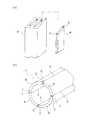
本発明の住宅用ダクト管の製造方法の実施形態の一例を図1、図2に基づいて説明する。この住宅用ダクト管の製造方法は、図1に示すような、発泡材料で一体成型された筒2の内周面3が内面被覆フィルム4で、外周面5が外面被覆フィルム6で夫々被覆された住宅用ダクト管1を製造する方法であって、以下の手順で住宅用ダクト管1を製造する。
(1)図2(a)に示すように、芯型7の外周に内面被覆フィルム4を予め巻いておく。内面被覆フィルム4としては、例えばグラスウールメッシュやポリプロピレンシート等の各種芯材(図示しない)の上にアルミ箔を貼り付けたアルミシート等を使用する。この場合、芯型7に離型剤を塗布する必要はない。
(2)図2(b)に示すように、内面被覆フィルム4を巻いた芯型7の外側に外型8を配置する。
(3)両型7、8間に発泡材料を充填し、発泡させて筒2を完成させる。このとき、芯型7に巻きつけた内面被覆フィルム4は筒2の内周面3に密着し、筒2の内周面3を被覆する。発泡材料の発泡倍率は例えば原液対比30倍とする等、任意とすることができる。また、発泡後の発泡材料の密度も任意とすることができる。
(4)外型8を外し、芯型7を抜いて、筒2を取り出す。なお、前記芯型7を抜く際に離型剤は必要ない。
(5)筒2の外周面5に外面被覆フィルム6を接着剤等によって密着させて貼り付け、図1に示すような住宅用ダクト管1を完成させる。外面被覆フィルム6としては、例えばアルミ箔等を使用する。(Embodiment 1 of the manufacturing method ofresidentialduct tube)
An example embodiment of a method for manufacturing aresidentialduct pipe of the present invention FIG. 1 will be described with reference to FIG. Method of manufacturing thisresidentialduct tube, as shown in FIG. 1, the inner
(1) As shown in FIG. 2 (a), the inner
(2) As shown in FIG. 2B, the
(3) A foam material is filled between the
(4) The
(5) the outer
(住宅用ダクト管の製造方法の実施形態2)
本発明の住宅用ダクト管の製造方法では、外型8の内面に予め外面被覆フィルム6を備えておき、両型7、8間に発泡材料を充填し、発泡させることによって、筒2の外周面5に外面被覆フィルム6を密着させることもできる。この場合、外面被覆フィルム6の貼り付けには接着剤が不要である。(
In the method of manufacturing aresidentialduct pipe of the present invention, previously provided with an outer surface coated
(住宅用ダクト管の製造方法のその他の実施形態)
筒2の外周面5の外面被覆フィルム6を省略して住宅用ダクト管1を完成させることもできる。(Other embodiment of a method for manufacturing aresidentialduct tube)
It may be omitted an outer
(住宅用ダクト管の実施形態1)
本発明の住宅用ダクト管の実施形態の一例を図1に基づいて説明する。本発明の住宅用ダクト管1は、前記製造方法によって製造される住宅用ダクト管であって、図1に示すように、発泡材料で一体成型された筒2の内周面3が内面被覆フィルム4で、外周面5が外面被覆フィルム6で夫々被覆されてなるものである。(According to the first embodiment of theresidentialduct tube)
An example embodiment ofresidentialduct pipe of the present invention will be described with reference to FIG.Residentialduct tube 1 of the present invention, the aresidentialduct pipe manufactured by the manufacturing method, as shown in FIG. 1, the inner
図1の筒2は、発泡材料で一体成型された筒状部材である。筒2の成型に用いられる発泡材料としては、例えばウレタンや発泡スチロール等、任意の発泡材料を用いることができるが、断熱性のある素材を使用することが望ましい。筒2の発泡材料の発泡倍率は例えば原液対比30倍とする等、任意とすることができる。また、発泡後の発泡材料の密度も任意とすることができる。また、この筒2は、蛇腹状に成型して可撓性を備えるものとすることもできる。 A
図1の内面被覆フィルム4は、筒2の成型時に内周面3に密着させて備えられ、内周面3を被覆する表面が平滑なフィルム状部材である。この内面被覆フィルム4の筒2の内周面3への密着は、接着剤を用いずに行われている。この内面被覆フィルム4には、例えばグラスウールメッシュやポリプロピレンシート等の各種芯材(図示しない)の上にアルミ箔を貼り付けたアルミシート等を使用することができる。もっとも、内面被覆フィルム4は前記アルミシートには限られず、樹脂膜等、有害物質を発散せず、表面が平滑あれば任意のフィルムや膜やシート状部材等を用いることができる。この内面被覆フィルム4を備えることにより、筒2の内部空間13を通過するエアに、発泡材料の微粉末や、各種有害物質(例えば、フロン、ジクロロメタン、ヘキサン、ベンゼン、トルエン、アセトン、酢酸等)が混入するおそれが殆どなくなり、ダクトを通過したエアが人体に悪影響を与えることがなくなる。また、内面被覆フィルム4の表面が平滑であるため、通過するエアの抵抗が少なくなり、スムースにエアを通過させることができるようになる。 The inner
図1の外面被覆フィルム6は、筒2の外周面5に密着させて備えられ、外周面5を被覆するフィルム状部材である。この外面被覆フィルム6は、筒2の成型後に接着剤を用いて外周面5に貼り付けることも、筒2の成型時に外型8内に備えておき、接着剤を用いずに密着させることもできる。外面被覆フィルム6としては前記内面被覆フィルム4と同様に、アルミ箔や樹脂膜等、有害物質を発散しないものであれば任意のフィルムや膜やシート状部材等を用いることができる。この外面被覆フィルム6を備えることにより、住宅用ダクト管1の強度や耐水性を向上させることができる。The outer
(住宅用ダクト管の実施形態2)
本発明の住宅用ダクト管では、筒2の外周面5の外面被覆フィルム6を省略することもできる。(Second embodiment of theresidentialduct tube)
Inresidentialduct pipe of the present invention, it is also possible to omit the outer
(住宅用ダクト管の連結構造の実施形態1)
本発明の住宅用ダクト管の連結構造の実施形態の一例を図3に基づいて説明する。この連結構造は、図3に示すように、外周に鍔11が形成された筒状のソケット10を用いて、前記住宅用ダクト管1を二本長手方向に連結させる構造である。この連結構造によって二本の住宅用ダクト管1を連結させるには、図3に示すように、一方の住宅用ダクト管1(図中右側)の軸方向端部内面に前記鍔11を嵌入させる凹部12を形成し、その一方の住宅用ダクト管1の内部空間13にソケット10の一端側を嵌入し、且つ、鍔11を凹部12に嵌入し、他方の住宅用ダクト管1(図中左側)の内部空間13にソケット10の他端側を嵌入させて、両住宅用ダクト管1の軸方向端面同士を突き合わせて両住宅用ダクト管1を連結する。連結された二本の住宅用ダクト管1の内部空間13同士は筒状のソケット10によって連通され、エアを漏らさず通過させられる。また、ソケット10の鍔11が凹部12内に嵌入されるため、ソケット10と鍔11のいずれも外周面5に露出せず、外観も良い。(Embodiment 1 of the coupling structureofresidentialduct tube)
An example of embodiment of the coupling structureofresidentialduct pipe of the present invention will be described with reference to FIG. This connection structure, as shown in FIG. 3, with a
(住宅用ダクト管の連結構造のその他の実施形態)
本発明の住宅用ダクト管の連結構造では、連結する二本の住宅用ダクト管1の双方の軸方向端部内側に凹部12を備え、ソケット10の鍔11を双方の凹部12内に半分ずつ嵌入させて、両住宅用ダクト管1の軸方向端面同士を突き合わせて両住宅用ダクト管1同士を連結させることもできる。この他にも、外周に鍔11が形成された筒状のソケット10を用いて、前記住宅用ダクト管1を二本長手方向に連結させられれば任意の構造とすることもできる。(Other embodiments of the connection structureofresidentialduct tube)
In the connection structureofresidentialduct pipe of the present invention is provided with tworesidential both
本発明の住宅用ダクト管の製造方法、その製造方法で製造した住宅用ダクト管、住宅用ダクト管の連結構造は、エアダクト用の住宅用ダクト管に限らず、任意の管状部材に応用することもできる。Method of manufacturing aresidentialduct pipe of the present invention,residentialduct tube was prepared in the manufacturing process, the coupling structureofresidentialduct tube is not limited toresidentialduct tube for air duct, any tubular member It can also be applied to.
1住宅用ダクト管
2 筒
3 内周面
4 内面被覆フィルム
5 外周面
6 外面被覆フィルム
7 芯型
8 外型
10 ソケット
11 鍔
12 凹部
13 内部空間
1
Claims (3)
Translated fromJapanesePriority Applications (1)
| Application Number | Priority Date | Filing Date | Title |
|---|---|---|---|
| JP2007277427AJP5108451B2 (en) | 2007-10-25 | 2007-10-25 | Manufacturing method of residential duct pipe, residential duct pipe, and connecting structure of residential duct pipe |
Applications Claiming Priority (1)
| Application Number | Priority Date | Filing Date | Title |
|---|---|---|---|
| JP2007277427AJP5108451B2 (en) | 2007-10-25 | 2007-10-25 | Manufacturing method of residential duct pipe, residential duct pipe, and connecting structure of residential duct pipe |
Publications (2)
| Publication Number | Publication Date |
|---|---|
| JP2009103396A JP2009103396A (en) | 2009-05-14 |
| JP5108451B2true JP5108451B2 (en) | 2012-12-26 |
Family
ID=40705231
Family Applications (1)
| Application Number | Title | Priority Date | Filing Date |
|---|---|---|---|
| JP2007277427AActiveJP5108451B2 (en) | 2007-10-25 | 2007-10-25 | Manufacturing method of residential duct pipe, residential duct pipe, and connecting structure of residential duct pipe |
Country Status (1)
| Country | Link |
|---|---|
| JP (1) | JP5108451B2 (en) |
Families Citing this family (1)
| Publication number | Priority date | Publication date | Assignee | Title |
|---|---|---|---|---|
| JP6745552B1 (en)* | 2019-11-15 | 2020-08-26 | 株式会社エスコ | Duct fitting |
Family Cites Families (12)
| Publication number | Priority date | Publication date | Assignee | Title |
|---|---|---|---|---|
| JPS56136337A (en)* | 1980-03-28 | 1981-10-24 | Sekisui Chem Co Ltd | Production of warming tube |
| JPH0231093A (en)* | 1988-07-16 | 1990-02-01 | Arisawa Mfg Co Ltd | FRP pipe with film adhered to the inner surface and its manufacturing method |
| JPH0510577A (en)* | 1991-07-01 | 1993-01-19 | Sekisui Chem Co Ltd | Piping material and ventilating device |
| JP3348896B2 (en)* | 1993-01-11 | 2002-11-20 | 三菱樹脂株式会社 | Forming method of tube spout |
| JPH074627A (en)* | 1993-06-18 | 1995-01-10 | Sanyo Electric Co Ltd | Incinerator |
| JPH0768672A (en)* | 1993-06-23 | 1995-03-14 | Sekisui Chem Co Ltd | Treatment of pipe end of foamed resin pipe and connection structure |
| JPH08320095A (en)* | 1994-11-10 | 1996-12-03 | Nippon Maintech Kk | Polyethylene pipe connecting method and polyethylene pipe |
| JP3318160B2 (en)* | 1995-08-18 | 2002-08-26 | 松下精工株式会社 | Pipe fittings |
| JPH09222185A (en)* | 1995-11-22 | 1997-08-26 | Sekisui Chem Co Ltd | Composite pipe and its manufacture |
| JPH1194341A (en)* | 1997-09-22 | 1999-04-09 | Shigeo Morimoto | Sound proof and heat insulating hose and manufacture therefor |
| JP2000246262A (en)* | 1999-03-03 | 2000-09-12 | Nuclear Fuel Ind Ltd | Method of reducing sludge generated when removing heavy metals from waste liquid |
| JP2002235948A (en)* | 2001-02-09 | 2002-08-23 | Shinko Kogyo Co Ltd | Air conditioner |
- 2007
- 2007-10-25JPJP2007277427Apatent/JP5108451B2/enactiveActive
Also Published As
| Publication number | Publication date |
|---|---|
| JP2009103396A (en) | 2009-05-14 |
Similar Documents
| Publication | Publication Date | Title |
|---|---|---|
| CA2873587C (en) | Hybrid component and production method | |
| US20030051764A1 (en) | Air handling system ductwork component and method of manufacture | |
| KR20130122769A (en) | Fluid handling assembly having a multilayered composite pipe employing a mechanical coupling and method of assembling the fluid handling assembly | |
| JP5108451B2 (en) | Manufacturing method of residential duct pipe, residential duct pipe, and connecting structure of residential duct pipe | |
| US20090152775A1 (en) | Method and apparatus for manufacturing of an article including an empty space | |
| US20180356117A1 (en) | HVAC Duct System, Method and Machine | |
| CN101634376A (en) | Compound air duct and method thereof | |
| JP4592351B2 (en) | Corrugated flexible tube | |
| CN104708839A (en) | Manufacturing method and equipment for prefabricated polyethylene foamed heat-insulating pipe | |
| JP2992508B2 (en) | Manufacturing method of composite pipe | |
| JP3682204B2 (en) | Method of manufacturing a water heater | |
| JP4978948B2 (en) | Manufacturing method of pipe lining material | |
| JP5843139B2 (en) | Paper round cylindrical duct | |
| JPH0725540Y2 (en) | Air duct connection structure | |
| JP2010185578A (en) | Method of forming and manufacturing corrugated flexible pipe | |
| FI127375B (en) | Pipes and process for the manufacture of a pipe | |
| JP2009008276A (en) | Knock-down duct | |
| JP4488501B2 (en) | Insulating duct and inner surface layer exchange method thereof | |
| JP2873199B2 (en) | Elbow insulation unit and method of using elbow insulation unit | |
| CN101223396A (en) | Improved multilayer composite pipe | |
| JPS639834Y2 (en) | ||
| KR102218180B1 (en) | Sleeves for dry air ducts equipped with foam and their manufacturing methods | |
| JP2004324803A (en) | Line forming tube | |
| JP2017025967A (en) | Shell | |
| JPH0510552B2 (en) |
Legal Events
| Date | Code | Title | Description |
|---|---|---|---|
| A621 | Written request for application examination | Free format text:JAPANESE INTERMEDIATE CODE: A621 Effective date:20100921 | |
| A977 | Report on retrieval | Free format text:JAPANESE INTERMEDIATE CODE: A971007 Effective date:20120126 | |
| A131 | Notification of reasons for refusal | Free format text:JAPANESE INTERMEDIATE CODE: A131 Effective date:20120221 | |
| A521 | Request for written amendment filed | Free format text:JAPANESE INTERMEDIATE CODE: A523 Effective date:20120420 | |
| TRDD | Decision of grant or rejection written | ||
| A01 | Written decision to grant a patent or to grant a registration (utility model) | Free format text:JAPANESE INTERMEDIATE CODE: A01 Effective date:20120911 | |
| A01 | Written decision to grant a patent or to grant a registration (utility model) | Free format text:JAPANESE INTERMEDIATE CODE: A01 | |
| A61 | First payment of annual fees (during grant procedure) | Free format text:JAPANESE INTERMEDIATE CODE: A61 Effective date:20121005 | |
| R150 | Certificate of patent or registration of utility model | Ref document number:5108451 Country of ref document:JP Free format text:JAPANESE INTERMEDIATE CODE: R150 Free format text:JAPANESE INTERMEDIATE CODE: R150 | |
| FPAY | Renewal fee payment (event date is renewal date of database) | Free format text:PAYMENT UNTIL: 20151012 Year of fee payment:3 | |
| R250 | Receipt of annual fees | Free format text:JAPANESE INTERMEDIATE CODE: R250 | |
| R250 | Receipt of annual fees | Free format text:JAPANESE INTERMEDIATE CODE: R250 | |
| R250 | Receipt of annual fees | Free format text:JAPANESE INTERMEDIATE CODE: R250 | |
| R250 | Receipt of annual fees | Free format text:JAPANESE INTERMEDIATE CODE: R250 | |
| R250 | Receipt of annual fees | Free format text:JAPANESE INTERMEDIATE CODE: R250 | |
| R250 | Receipt of annual fees | Free format text:JAPANESE INTERMEDIATE CODE: R250 | |
| R250 | Receipt of annual fees | Free format text:JAPANESE INTERMEDIATE CODE: R250 | |
| R250 | Receipt of annual fees | Free format text:JAPANESE INTERMEDIATE CODE: R250 | |
| R250 | Receipt of annual fees | Free format text:JAPANESE INTERMEDIATE CODE: R250 | |
| R250 | Receipt of annual fees | Free format text:JAPANESE INTERMEDIATE CODE: R250 |