JP5104773B2 - Data transfer system, data transfer device, and data transfer method - Google Patents
Data transfer system, data transfer device, and data transfer methodDownload PDFInfo
- Publication number
- JP5104773B2 JP5104773B2JP2009031267AJP2009031267AJP5104773B2JP 5104773 B2JP5104773 B2JP 5104773B2JP 2009031267 AJP2009031267 AJP 2009031267AJP 2009031267 AJP2009031267 AJP 2009031267AJP 5104773 B2JP5104773 B2JP 5104773B2
- Authority
- JP
- Japan
- Prior art keywords
- signal line
- data
- transmission
- unit
- reception
- Prior art date
- Legal status (The legal status is an assumption and is not a legal conclusion. Google has not performed a legal analysis and makes no representation as to the accuracy of the status listed.)
- Expired - Fee Related
Links
Images


Classifications
- H—ELECTRICITY
- H04—ELECTRIC COMMUNICATION TECHNIQUE
- H04L—TRANSMISSION OF DIGITAL INFORMATION, e.g. TELEGRAPHIC COMMUNICATION
- H04L69/00—Network arrangements, protocols or services independent of the application payload and not provided for in the other groups of this subclass
- H04L69/40—Network arrangements, protocols or services independent of the application payload and not provided for in the other groups of this subclass for recovering from a failure of a protocol instance or entity, e.g. service redundancy protocols, protocol state redundancy or protocol service redirection
- H—ELECTRICITY
- H04—ELECTRIC COMMUNICATION TECHNIQUE
- H04L—TRANSMISSION OF DIGITAL INFORMATION, e.g. TELEGRAPHIC COMMUNICATION
- H04L69/00—Network arrangements, protocols or services independent of the application payload and not provided for in the other groups of this subclass
- H04L69/14—Multichannel or multilink protocols
- H—ELECTRICITY
- H04—ELECTRIC COMMUNICATION TECHNIQUE
- H04L—TRANSMISSION OF DIGITAL INFORMATION, e.g. TELEGRAPHIC COMMUNICATION
- H04L69/00—Network arrangements, protocols or services independent of the application payload and not provided for in the other groups of this subclass
- H04L69/28—Timers or timing mechanisms used in protocols
Landscapes
- Engineering & Computer Science (AREA)
- Computer Security & Cryptography (AREA)
- Computer Networks & Wireless Communication (AREA)
- Signal Processing (AREA)
- Data Exchanges In Wide-Area Networks (AREA)
Description
Translated fromJapanese本願発明はデータ転送システム、データ転送装置およびデータ転送方法に係り、特に複数の信号線の他に代替信号線を使用してパケットの送信を行うデータ転送システム、データ転送装置およびデータ転送方法に関する。 The present invention relates to a data transfer system, a data transfer apparatus, and a data transfer method, and more particularly, to a data transfer system, a data transfer apparatus, and a data transfer method for transmitting a packet using alternative signal lines in addition to a plurality of signal lines.
制御データである制御パケットの送信において、制御パケットを、マルチリンクを構成する回線群の2本の回線にだけ送信し、通常のデータパケットを回線群内の前記2本以外の回線のどれかに分散して送信する技術が提案されている。 In transmitting a control packet which is control data, the control packet is transmitted only to two lines of the line group constituting the multilink, and a normal data packet is transmitted to any one of the lines other than the two lines in the line group. Techniques for transmitting in a distributed manner have been proposed.
またデータ伝送において、障害発生経路を特定し切り離し、正常経路のみでデータ転送を再構築し代替的に伝送を可能とする技術が提案されている。 In data transmission, a technique has been proposed in which a failure occurrence path is identified and separated, data transfer is reconstructed using only a normal path, and transmission can be performed alternatively.
複数の信号線および代替信号線を使用してデータパケットおよび制御パケットを送信する際、複数の信号線および代替信号線の効率的な利用を図ることを目的とする。 It is an object of the present invention to efficiently use a plurality of signal lines and alternative signal lines when transmitting data packets and control packets using the plurality of signal lines and alternative signal lines.
データ転送システムにおいて、複数の信号線の正常時にはデータ本体としてのデータパケットを複数の信号線で送信する一方、制御データとしての制御パケットを代替信号線で送信し、複数の信号線のいずれかの故障時にはデータパケットおよび制御パケットを故障信号線以外の信号線および代替信号線で送信する。 In a data transfer system, when a plurality of signal lines are normal, a data packet as a data body is transmitted through a plurality of signal lines, while a control packet as control data is transmitted through an alternative signal line and one of the plurality of signal lines is transmitted. When a failure occurs, the data packet and the control packet are transmitted through a signal line other than the failure signal line and an alternative signal line.
複数の信号線の正常時にはデータパケットを複数の信号線で送信する一方、制御パケットを代替信号線で送信するため、複数の信号線および代替信号線の効率的な利用が実現できる。 When the plurality of signal lines are normal, the data packet is transmitted through the plurality of signal lines, while the control packet is transmitted through the alternative signal line. Therefore, efficient use of the plurality of signal lines and the alternative signal line can be realized.
実施例は、データ送信装置とデータ受信装置との間が複数の信号線によって接続され、当該複数の信号線を用いてパケットの転送を行うデータ転送システムに係る。当該データ転送システムにおいては、前記複数の信号線に異常があった際に当該異常があった信号線の代わりに使用することができる代替信号線が用意されている。当該データ転送システムでは、前記複数の信号線が正常の場合、前記代替信号線に制御パケットを通すため、以下に述べる構成を設けた。すなわちデータ送信装置において、複数種類の制御パケットのうち、いずれの制御パケットを代替信号線に通すかを選択する選択回路と、制御パケットを代替信号線に送出する送信部とを設けた。またデータ受信装置に届いた、代替信号線で受信された制御パケットを受信する代替信号線受信部をデータ受信装置に設ける。このように実施例によれば前記複数の信号線が正常の場合、代替信号線に制御パケットを通すため、複数の信号線が正常である場合のパケットの転送の効率をあげることができる。 The embodiment relates to a data transfer system in which a data transmission device and a data reception device are connected by a plurality of signal lines, and packets are transferred using the plurality of signal lines. In the data transfer system, an alternative signal line that can be used in place of the signal line having the abnormality when the plurality of signal lines are abnormal is prepared. In the data transfer system, when the plurality of signal lines are normal, the configuration described below is provided in order to pass the control packet through the alternative signal line. In other words, the data transmission apparatus includes a selection circuit that selects which control packet is to be passed through the alternative signal line from among a plurality of types of control packets, and a transmission unit that transmits the control packet to the alternative signal line. In addition, the data receiving apparatus is provided with an alternative signal line receiving unit that receives the control packet received by the alternative signal line that has reached the data receiving apparatus. As described above, according to the embodiment, when the plurality of signal lines are normal, the control packet is passed through the alternative signal line. Therefore, the efficiency of packet transfer when the plurality of signal lines is normal can be increased.
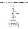
図1は実施例のデータ転送システムを構成する情報処理装置(以下単に情報処理装置と称する)の全体構成を示すブロック図である。当該情報処理装置は、それぞれがデータ送信装置又はデータ受信装置として、或いはデータ送信装置およびデータ受信装置としての機能を有する複数のLSIを含む。 FIG. 1 is a block diagram illustrating an overall configuration of an information processing apparatus (hereinafter simply referred to as an information processing apparatus) that constitutes a data transfer system according to an embodiment. The information processing apparatus includes a plurality of LSIs each having a function as a data transmission apparatus or a data reception apparatus or as a data transmission apparatus and a data reception apparatus.
当該情報処理装置は図1に示す如く、演算処理装置としてのCPU(Central Processing Unit)11およびメモリ制御装置としてのMCU(Memory Control Unit)12を有する。当該情報処理装置は更に、記憶装置としてのメモリ13、I/O装置制御装置としてのIOU(Input/Output Unit)14およびI/Oアダプタ15〜17を有する。当該情報処理装置の構成要素中、CPU11、MCU12、IOU14およびI/Oアダプタ15〜17の各々は、データ送信装置又はデータ受信装置として、或いはデータ送信装置およびデータ受信装置としての機能を有するLSIである。ここで上記データ送信装置又はデータ受信装置として、或いはデータ送信装置およびデータ受信装置としての機能を有するLSIは又、データ転送装置としての機能を有するLSIでもある。 As shown in FIG. 1, the information processing apparatus includes a CPU (Central Processing Unit) 11 as an arithmetic processing unit and an MCU (Memory Control Unit) 12 as a memory control unit. The information processing apparatus further includes a
CPU11は種々の演算処理および当該情報処理装置全体の制御を行う。メモリ13はCPU11が前記演算処理および制御を行う際に使用する各種データを格納するとともに、当該演算処理および制御をCPU11に実行させるためのプログラムを格納する。MCU12はメモリ13並びにIOU14およびI/Oアダプタ15〜17を介して外部に接続されるディスク等の入出力装置が格納する情報を管理する。I/Oアダプタ15〜17は当該情報処理装置の外部に接続される上記入出力装置との間の情報のやりとりに必要なインタフェースを提供する。IOU14は複数のI/Oアダプタ15〜17を介して情報処理装置の外部に接続される入出力装置をまとめて管理する。 The CPU 11 performs various arithmetic processes and controls the entire information processing apparatus. The
図1中、CPU11とMCU12との間のデータの転送、MCU12とIOU14との間のデータの転送、IOU14とI/Oアダプタ15〜17の各々との間のデータ転送の各々において、複数の信号線および代替信号線が使用される。ここで上記の如く、CPU11、MCU12、IOU14およびI/Oアダプタ15〜17の各々はデータ送信装置又はデータ受信装置として、或いはデータ送信装置およびデータ受信装置として機能する。したがってCPU11、MCU12、IOU14およびI/Oアダプタ15〜17の各々を、データ送信装置として機能する場合にはデータ送信装置と称し、データ受信装置としての機能する場合にはデータ受信装置と称する場合がある。更にCPU11、MCU12、IOU14およびI/Oアダプタ15〜17の各々をデータ転送装置と称する場合もある。 In FIG. 1, a plurality of signals are used in each of data transfer between the CPU 11 and the
上記の如くデータ送信装置とデータ受信装置との間のデータの転送に複数の信号線および代替信号線が使用される実施例の情報処理装置では、当該データ送信装置とデータ受信装置との間で、通常のデータパケット(すなわちメモリリード、メモリライト、キャッシュコヒーレンシに関する命令等を格納したパケットをいい、以下単にデータパケットと称する。)が転送される。更に当該データ送信装置とデータ受信装置との間でデータパケット以外に、データ送信装置とデータ受信装置との間のパケットの転送を制御するフロー制御パケット、割り込みによるパケット等が転送される。以下に参考例のデータ送信装置とデータ受信装置との間のパケットの転送の方法につき、図2〜5とともに説明する。 In the information processing apparatus of the embodiment in which a plurality of signal lines and alternative signal lines are used for data transfer between the data transmission apparatus and the data reception apparatus as described above, between the data transmission apparatus and the data reception apparatus. A normal data packet (that is, a packet storing instructions relating to memory read, memory write, cache coherency, and the like, hereinafter simply referred to as a data packet) is transferred. Further, in addition to the data packet, a flow control packet for controlling transfer of the packet between the data transmission device and the data reception device, a packet due to an interrupt, and the like are transferred between the data transmission device and the data reception device. A method for transferring packets between the data transmitting apparatus and the data receiving apparatus of the reference example will be described below with reference to FIGS.
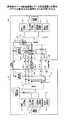
参考例のデータ送信装置とデータ受信装置との間のパケットの転送では、図3に示されるごとく、前記複数の信号線w1〜wNが正常の場合、データパケットおよび制御パケットが当該複数の信号線w1〜wNを使用してデータ送信装置とデータ受信装置との間を転送される。ここでデータ送信装置とデータ受信装置との間とは、図2〜図5に示される、データ送信装置100とデータ受信装置200との間をいう(以下同様)。ここで制御パケットとはフロー制御パケット、送達確認パケットおよびで割り込みパケットのうちの何れかのパケットをいう(以下同様)。またフロー制御パケット、送達確認パケットおよびで割り込みパケットは、それぞれ図2とともに後述するフロー制御パケット生成回路112、送達確認パケット生成回路113および割り込みパケット生成回路114で生成される。In the transfer of the packet between the data transmitting device and the data receiving device of the reference example, as shown in FIG. 3, when the plurality of signal lines w1 to wN are normal, the data packet and the control packet The signal lines w1 to wN are transferred between the data transmitting device and the data receiving device. Here, between the data transmitting device and the data receiving device means between the
ここで当該複数の信号線w1〜wNのうちのいずれかが何らかの原因で故障してしまった場合を想定する。この場合、上記故障した信号線はパケットの転送に使用できなくなる。この場合に上記故障した信号線の代わりに使用する信号線として、代替信号線wSが用意されている。その結果、上記故障した信号線を代替信号線wSと交換することにより、前記信号線の故障前と同様の態様にてパケットの転送を続けることができるようになる。当該参考例では前記複数の信号線のいずれにも故障が発生していない場合、前記代替信号線wSはパケットの転送には使用されない。すなわち参考例の場合、代替信号線wSは純粋な予備線として使用される。Here, it is assumed that any one of the plurality of signal lines w1 to wN has failed for some reason. In this case, the failed signal line cannot be used for packet transfer. In this case, an alternative signal line wS is prepared as a signal line to be used in place of the failed signal line. As a result, by exchanging the failed signal line with the alternative signal line wS , packet transfer can be continued in the same manner as before the signal line failure. In the reference example, when no failure occurs in any of the plurality of signal lines, the alternative signal line wS is not used for packet transfer. That is, in the case of the reference example, the alternative signal line wS is used as a pure spare line.
当該参考例のデータ送信装置とデータ受信装置との間のパケットの転送方法につき、図2〜図5とともに以下に詳細に説明する。 A method for transferring a packet between the data transmitting apparatus and the data receiving apparatus of the reference example will be described in detail below with reference to FIGS.
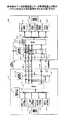
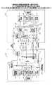
図2は、データ送信装置100およびデータ受信装置200のそれぞれにおける、双方間のパケットの転送に係る部分を特に抽出して示す。なお当該データ送信装置100およびデータ受信装置200における当該データ送信装置とデータ受信装置との間のパケットの転送に係る部分以外の構成は、それぞれ周知のCPU、MCU等のLSIと同様の構成とすることができ、ここでの詳細な説明を省略する。 FIG. 2 particularly shows a part relating to packet transfer between the
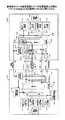
図3は図2の構成において、通常時、すなわち複数の信号線w1〜wNのいずれもが正常である場合の、各パケットの流れを示す。図4は図2の構成において、複数の信号線w1〜wNのうちの何れかが故障し、当該故障が検知され、故障した信号線が代替信号線wSに切り替えられる際の信号の流れを示す。図5は図2の構成において、上記の如く故障した信号線が代替信号線wSに切り替えられた後の、各パケットの流れを示す。FIG. 3 shows the flow of each packet in the configuration of FIG. 2 at the normal time, that is, when all of the signal lines w1 to wN are normal. FIG. 4 shows the signal when the signal line w1 to wN fails in the configuration of FIG. 2, the failure is detected, and the failed signal line is switched to the alternative signal line wS. Show the flow. FIG. 5 shows the flow of each packet after the failed signal line is switched to the alternative signal lineWS in the configuration of FIG.
図2に示される如く、データ送信装置とデータ受信装置との間には、パケットの転送のためのN本の信号線w1〜wNと、当該N本の信号線w1〜wNのいずれかが故障した際に切り替えるための代替信号線wSと、前記故障した信号線の切り替えタイミングを通知する故障通知信号を送信するための信号線wFとが接続されている。上記N本の信号線w1〜wNは、データ送信装置100,データ受信装置200のそれぞれに設けられているN個の送信バッファ120−1〜120−NとN個の受信バッファ210−1〜210−Nとの間をそれぞれ接続している。又代替信号線wSは、データ送信装置100の送信バッファ121と、データ受信装置200の受信バッファ211との間を接続している。又故障通知信号の送信のための信号線wFは、図示の如く、データ送信装置100に設けられた信号線選択指示回路118と、データ受信装置200に設けられた信号線選択指示回路212との間を接続している。As shown in FIG. 2, between the data transmission apparatus and the data receiving apparatus, the N signal lines w1 to wN for the transfer of packets, of the N signal lines w1 to wN An alternative signal line wS for switching when one of the faults is connected to a signal line wF for transmitting a fault notification signal for notifying the switching timing of the faulty signal line. The N signal lines w1 to wN include N transmission buffers 120-1 to 120 -N and N reception buffers 210-1 provided in the
データ送信装置100中、データ受信装置200に対するパケットの送信に係る部分には、データパケットを生成する通常データパケット生成回路111が設けられている。更にデータ送信装置100中、データ受信装置200に対するパケットの送信に係る部分には、データ受信装置200の受信バッファの空き状況を通知するためのフロー制御パケットを生成するフロー制御パケット生成部112が設けられている。又データ送信装置100中、データ受信装置200の対するパケットの送信に係る部分には、受信したパケットが正常に受信できたかを通知するための送達確認パケットを生成する送達確認パケット生成回路113と、割り込みパケットを生成制するための割り込みパケット生成回路114とが設けられている。 In the
更にデータ送信装置100中のデータ受信装置200に対するパケットの送信に係る部分には、データ受信装置に対し送信するパケットを選択する送信パケット選択回路115が設けられている。更にデータ送信装置100中のデータ受信装置200に対するパケットの送信に係る部分には、送信するパケットをN個に分割して上記N本の信号線w1〜wNのそれぞれに送出する送信部117が設けられている。更に送信パケット選択回路115の制御の下、送信するパケットを選択して送信部117に入力するマルチプレクサ116が設けられている。更にデータ送信装置100中、データ受信装置200に対するパケットの送信に係る部分には、複数の信号線w1〜wN中の何れかの信号線の故障が検知された場合に、故障した信号線を切り離し、代替信号線wSに切り替える信号線選択指示回路118が設けられている。また信号線選択指示部118の制御下、送信部117から出力される信号のうち、代替信号線wSに送出する信号を選択して代替信号線wSに送出するマルチプレクサ119が設けられている。Furthermore, a transmission
他方データ受信装置200中、データ送信装置100からのパケットの受信に係る部分には、受信したデータパケットを処理する通常データパケット処理部216と,上記フロー制御パケットを処理するフロー制御パケット処理部217とが設けられている。またデータ受信装置200中、データ送信装置100からのパケットの受信に係る部分には、上記送達確認パケットを処理する送達確認パケット処理部218と、上記割り込みパケットを処理する割り込みパケット処理部219とが設けられている。更にデータ受信装置200中、データ送信装置100からのパケットの受信に係る部分には、N本の信号線w1〜wNに分割されて送信されてきたパケットを組み立て直す受信部214と、信号線の異常を検出する故障検知回路214dとが設けられている。またデータ受信装置200中、データ送信装置100からのパケットの受信に係る部分には、故障検知回路214dによる故障検知時に故障した信号線を切り離し代替信号線wSに切り替える信号線選択指示回路212が設けられている。更にデータ受信装置200中、データ送信装置100からのパケットの受信に係る部分には、N本の信号線w1〜wNのそれぞれに対し設けられ、対応する信号線および代替信号線wSの何れかを選択するN個のマルチプレクサ213−1〜213−Nが設けられている。上記N個のマルチプレクサ213−1〜213−Nは信号線選択指示回路212の制御下で動作し、それぞれに選択された信号は受信部214に入力される。またデータ受信装置200中、データ送信装置100からのパケットの受信に係る部分には、受信部214から出力されるパケットを、上記それぞれの処理部216〜219のうちの対応する処理部に振り分けるデマルチプレクサ215が設けられている。On the other hand, in the data receiving device 200, the portion related to the reception of the packet from the
又データ送信装置100,データ受信装置200の各々には、データ送信装置100,データ受信装置200の各々に含まれる各部の動作を制御するための装置制御回路101,201が含まれている。 Each of the
以下に上記参考例のデータ送信装置とデータ受信装置との間のパケットの転送に係る動作の流れを説明する。 The flow of operations relating to packet transfer between the data transmitting device and the data receiving device of the reference example will be described below.
まず通常動作時、すなわちN本の信号線w1〜wNのいずれもが正常の場合の動作につき、図3とともに説明する。この場合、データ送信装置100において、各パケット生成回路111〜114からのパケットの送信要求に応じ、送信パケット選択回路115の制御下、マルチプレクサ116が送信するパケットを選択して送信部117に入力する。送信部117は入力されたパケットをN個に分割してそれぞれN本の信号線w1〜wNに送出する。データ受信装置200の受信部214は、当該N個に分割されてN本の信号線w1〜wNで送信されてきたパケットを組み立て直し、得られたパケットが正しく受信できたかを判断する。正しく受信できたとの判断が得られた場合、受信部214は当該パケットの種類に応じ、それぞれのパケット処理部216〜219のうち対応するパケット処理部に振り分ける。他方受信部214における上記判断において、上記得られたパケットに異常が検出された場合、故障検知回路214dはN本の信号線w1〜wNにおいてになんからの故障が発生したと判断する。上記正しく受信されたとの判断が得られたパケットは対応するパケット処理部で内容が解析され、必要な処理が実行される。故障検知回路214dにて、異常が発生した信号線を特定するため、予めデータ送信装置100の各パケット生成部111〜114では、生成するパケットに、故障した信号線を特定するためのエラーチェックコード(すなわちECC、以下同様)を付加する。なお異常が発生した信号線を特定するための具体的な方法につき、図10,11とともに後述する。また、N本の信号線w1〜wNのいずれもが正常の場合には、代替信号線wSは何らデータの転送に使用されない。First, the operation during normal operation, that is, when all of the N signal lines w1 to wN are normal will be described with reference to FIG. In this case, in the
上記の如くデータ受信装置200の故障検知部214dが信号線の故障を検知したとき、以下の動作がなされる。すなわち図4に示されるように、データ受信装置200の故障検知回路214dがデータ受信装置200およびデータ送信装置100の双方のそれぞれの信号線選択指示回路212,118に対し、故障した信号線の情報と故障通知信号とを送る。データ受信装置200の信号線選択指示回路212は当該故障通知信号を受け取り、当該故障した信号線を代替信号線wSに切り替え、データ送信装置100においても同様に当該故障した信号線を代替信号線wSに切り替える。ここでは説明の便宜上、上記故障した信号線を信号線w3と仮定する。この場合、データ受信装置200の信号線選択指示回路212は対応するマルチプレクサ213−3に代替信号線wSを選択させる。他方、故障した信号線の情報と故障通知信号とを受けたデータ送信装置100の信号線選択指示回路118は、故障した信号線w3が接続されていた送信部117の出力端子に代替信号線wSが接続されるようにマルチプレクサ119を切り替える。その結果、データ送信装置100では元々信号線w3に送出されていた信号が代替信号線wSに送出されるようになる。同様にデータ受信装置200では、元々信号線w3を選択していたマルチプレクサ213−3が代替信号線wSを選択するようになる。したがって元々信号線w3によって送信されていた信号は代替信号線wSを使用して送信されるようになる。As described above, when the
上記の如く、データ受信装置200およびデータ送信装置100の双方の信号選択回路212,118の機能により元々信号線w3によって送信されていた信号は代替信号線wSを使用して送信されるようになる。その後、図5に示されるように、図3の場合同様、データパケット、フロー制御パケット、送達確認パケット、割り込みパケット等、全てのパケットが送信部117から送出される態様でパケットの転送が再開される。データ受信装置200においても同様に、受信部214が全てのパケットを受信する。上記した動作の結果、故障した信号線w3は切り離され、故障した信号線w3が担っていた信号の転送は代替信号線wSが担うようになる。このときデータ受信装置200では、データ送信装置100が故障した信号線w3を切り離し故障した信号線が担っていた信号の転送が代替信号線wSで担われるように切り替えがなされケットの転送が再開されるのを検知して、受信処理を再開する。ここでデータ受信装置200が上記データ送信装置100における信号線の接続の切り替えを検知するための方法として、以下の3つの方法が考えられる。
(第1の方法)
送信を再開する最初のパケットとして特殊パケットを用い、特殊パケットを検出することで再開を検知する。
(第2の方法)
送信側と受信側とで同じ時間を刻むタイマを用意しておき、信号線の切り替え指示後、決められたタイミングでパケットの転送を再開する。
(第3の方法)
外部に制御用装置を用意しておき、その外部制御装置によりパケットの転送再開のタイミングを通知する。As described above, the signal originally transmitted by the signal line w3 by the function of the
(First method)
The special packet is used as the first packet for restarting transmission, and the restart is detected by detecting the special packet.
(Second method)
A timer that ticks the same time is prepared on the transmission side and the reception side, and after a signal line switching instruction, packet transfer is resumed at a predetermined timing.
(Third method)
A control device is prepared outside, and the external control device notifies the timing of resuming packet transfer.
これら第1〜第3の方法については図14〜19とともに後述する。 These first to third methods will be described later with reference to FIGS.
ここで図2〜図5とともに上述した参考例のデータ送信装置とデータ受信装置との間のパケットの転送方法では、代替信号線wSは以下の機能を有する。すなわち、通常時にパケットの転送を行っている複数の信号線w1〜wNのいずれに故障が生じた際、当該故障した信号線に代わって信号の送信を継続させるための信号線として使用される。したがって通常時、すなわち複数の信号線w1〜wNのいずれもが正常の場合、代替信号線wSは使用されない。また当該参考例のデータ送信装置とデータ受信装置との間のパケットの転送において、データ送信装置100はデータ受信装置200の受信バッファの空き具合を確認しながら転送を行う。このため、受信バッファの大きさが十分にないと、受信バッファの空き具合を知らせるためのフロー制御パケットを頻繁に転送しなければならなくなる。このため、データパケットに対しフロー制御パケットの比率が大きくなりデータパケットの転送の効率が低下することが想定される。さらにネットワークアダプタのように他装置からのデータの受信があった時データを転送するようなデータ送信装置およびデータ受信装置の各々として機能するLSIの場合、データの受信があったことを知らせる割り込み制御を行う必要がある。この割り込み制御を行う制御パケットをデータパケットの転送と平行して行うのでデータパケットの転送の効率が低下することが想定される。Here, in the packet transfer method between the data transmitting apparatus and the data receiving apparatus of the reference example described above with reference to FIGS. 2 to 5, the alternative signal line wS has the following functions. That is, when a failure occurs in any of the plurality of signal lines w1 to wN that normally transfer packets, it is used as a signal line for continuing signal transmission instead of the failed signal line. The Therefore, the substitute signal line wS is not used at normal time, that is, when all of the plurality of signal lines w1 to wN are normal. Further, in the packet transfer between the data transmission device and the data reception device of the reference example, the
実施例のデータ送信装置とデータ受信装置との間のパケットの転送方法によれば、データ送信装置とデータ受信装置との間が複数の信号線によって接続され、当該複数の信号線を用いてパケットの転送を行う構成において、複数の信号線のいずれもが正常の場合、代替信号線を有効に活用する。その結果データパケットの転送効率をあげることが可能となり、情報処理装置の性能を向上させることができる。 According to the packet transfer method between the data transmission device and the data reception device of the embodiment, the data transmission device and the data reception device are connected by a plurality of signal lines, and the packet is transmitted using the plurality of signal lines. In the configuration in which the transfer is performed, when all of the plurality of signal lines are normal, the alternative signal line is effectively used. As a result, it is possible to increase the transfer efficiency of the data packet and improve the performance of the information processing apparatus.
すなわち実施例では、正常動作時において、代替信号線に、フロー制御や送達確認、割り込みなどの制御パケットを送出する。すなわちデータ送信装置にて、複数種の制御パケットのうち、いずれの種類の制御パケットを代替信号線に送出するかを選択する制御パケット送信選択回路と、制御パケットを代替信号線に送出する代替信号線送信部とを設ける。又データ受信装置には、データ受信装置に届いた、代替信号線を通ってきた制御パケットを受信する代替信号線受信部を設ける。 That is, in the embodiment, during normal operation, control packets such as flow control, delivery confirmation, and interrupt are sent to the alternative signal line. That is, in the data transmission device, a control packet transmission selection circuit that selects which type of control packet is to be sent to the alternative signal line from among a plurality of types of control packets, and an alternative signal that sends the control packet to the alternative signal line And a line transmission unit. The data receiving apparatus is provided with an alternative signal line receiving unit that receives a control packet that has reached the data receiving apparatus and has passed through the alternative signal line.
実施例によれば、参考例では正常動作時に使用していなかった代替信号線に、データパケットの転送に関するフロー制御、到達確認、割り込みなどの制御パケットを通す。その結果、データパケットの転送機会が増加し、パケットの転送効率が向上する。 According to the embodiment, control packets such as flow control related to data packet transfer, arrival confirmation, and interrupt are passed through an alternative signal line that is not used in normal operation in the reference example. As a result, data packet transfer opportunities increase, and packet transfer efficiency improves.
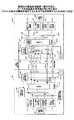
図6は実施例に係る、データ送信装置100Aおよびデータ受信装置200Aのうち、相互のパケットの転送に係るそれぞれの部分を抽出して示す。なお当該データ送信装置100Aおよびデータ受信装置200Aにおける相互のパケットの転送に係る部分以外の構成は、それぞれ周知のCPU、MCU等のLSIの構成と同様とすることができ、ここでの詳細な説明を省略する。 FIG. 6 shows extracted portions of the
実施例のデータ送信装置100Aおよびデータ受信装置200A中、相互のパケットの転送に係るそれぞれの部分において、上記参考例のデータ送信装置100およびデータ受信装置200中、相互のパケットの転送に係るそれぞれの部分におけるものと同一の部分に同じ符号を付し説明を省略する。 In the
実施例のデータ送信装置100A中、データ受信装置200Aに対するパケットの送信に係る部分には、送信する制御パケットを選択する制御パケット送信選択回路116Cと、選択された制御パケットを送信する送信部117Aとが設けられている。また実施例のデータ送信装置100A中、データ受信装置200Aに対するパケットの送信に係る部分には、信号線選択指示回路118Aから送信パケット選択回路115Aへの指示信号線が設けられている。すなわち、N本の信号線w1〜wNのうちのいずれかの故障が検出された際、信号線選択指示回路118Aにより、故障した信号線から代替信号線wSへと切り替えを行うための指示が出される。その際信号線選択指示回路118Aは上記指示信号線により送信パケット選択回路115Aに指示を与え、制御パケットが送信部117へ出力されるよう、切り替えを行わせる。更に実施例のデータ送信装置100A中、データ受信装置200Aに対するパケットの送信に係る部分は、3種の制御パケット中、いずれの種類の制御パケットを送信するかを選択するマルチプレクサ116Bを有する。マルチプレクサ116Bの動作は制御パケット送信選択回路116Cにより制御される。更に実施例のデータ送信装置100A中、データ受信装置200Aに対するパケットの送信に係る部分は、通常データパケット生成部で生成されるデータパケットと、マルチプレクサ116Bで選択される制御パケットとのうち、いずれを選択するマルチプレクサ116Aを有する。マルチプレクサ116Aの動作は送信パケット選択回路115Aにより制御される。In the
またデータ受信装置200A中、データ送信装置100Aからのパケットの受信に係る部分には、制御パケットを受信する受信部214Aと、信号線選択指示回路212Aがマルチプレクサ215Bを制御するための切り替え信号線とが設けられている。信号線選択指示回路212Aは、N本の信号線w1〜wNのうちのいずれかの故障時に故障した信号線の切り替え指示を行う。信号線選択指示回路212Aは又、受信部214から出力される制御パケットを対応するパケット処理部に振り分けるため、マルチプレクサ215Bを制御する。またデータ受信装置200A中、データ送信装置100Aからのパケットの受信に係る部分は、受信部214から出力されるパケットを通常データパケット処理部216およびマルチプレクサ215Bに振り分けるデマルチプレクサ215Aを有する。更に、マルチプレクサ215Bで選択された制御パケットを対応するパケット処理部へ振り分けるデマルチプレクサ215Cが設けられている。In the
以下図7〜9とともに、図6とともに上記した実施例に係るデータ送信装置100Aおよびデータ受信装置200Aの、相互間のパケットの転送に係る動作の流れを説明する。 Hereinafter, the flow of operations related to packet transfer between the
図7は通常動作時(すなわちN本の信号線w1〜wNのいずれもが正常の場合、以下同様)の各パケットの流れを示す。図8は信号線の故障が検知され代替信号線に切り替わる際の信号の流れを示し、図9は信号線の故障後に代替信号線に切り替わった後の各パケットの流れを示す。FIG. 7 shows the flow of each packet during normal operation (ie, when all of theN signal lines w1 to wN are normal). FIG. 8 shows the signal flow when a signal line failure is detected and switched to an alternative signal line, and FIG. 9 shows the flow of each packet after switching to the alternative signal line after a signal line failure.
通常動作時は図7で示されるように、データ送信装置100Aにおいて、通常データパケット生成回路111からデータパケットの送信要求があると、送信部117は上記データパケットをN個に分割し、N本の信号線w1〜wNに送出する。すなわちこの場合、データ送信装置100Aの送信パケット選択回路115Aはマルチプレクサ116Aを制御し、通常データパケット生成回路111を選択的に送信部117へ接続する。またデータ受信装置200Aの受信部214は、N本の信号線w1〜wNに分割して送信されてきたデータパケットを組み立て直し、当該データパケットが正しく受信できたことを確認した上で、当該データパケットを通常データパケット処理部216に送る。すなわちこの場合、データ受信装置200Aのマルチプレクサ213−1〜213−Nの各々は、信号線選択指示回路212Aの制御下、N本の信号線w1〜wNのうちの対応する信号線を選択的に受信部214に接続する。またデマルチプレクサ215Aは受信部214から出力されたパケットを通常データパケット処理部216へ渡す。In the normal operation, as shown in FIG. 7, in the
一方、各パケット生成回路112,113,114で生成された制御パケットはマルチプレクサ116Bを介して送信部117Aに送られ、更にマルチプレクサ119および送信バッファ121を介して代替信号線wSに送出される。データ受信装置200Aでは代替信号線wSで送信された当該制御パケットを受信バッファ211を介し受信部214Aが受信する。当該制御パケットは受信部214Aからマルチプレクサ215Bおよびデマルチプレクサ215Cを介し、該当する各パケット処理部217,218,219に振り分けられる。すなわちこの場合、データ送信装置100Aのマルチプレクサ116Bは制御パケット送信選択回路116Cの制御下、各制御パケット生成回路112,113,114で生成された制御パケットのうちの何れかの制御パケットを選択して送信部117Aに渡す。又マルチプレクサ119は信号線選択指示回路118Aの制御下、送信部117Aから出力されたパケットを選択的に代替信号線wSに送出する。データ受信装置200Aのマルチプレクサ215Bは信号線選択指示回路212Aの制御下、受信部214Aから出力されるパケットを選択的にデマルチプレクサ215Cに出力する。On the other hand, the control packet generated by each of the
ここでN本の信号線w1〜wNのうちの何れかの信号線の故障が生じた場合、図8に示されるように、データ受信装置200Aの故障検知回路214dが前記信号線の故障を検知する。ここでは説明の便宜上、信号線w3が故障した場合を想定する。上記故障検知回路214dはデータ受信装置200A、データ送信装置100Aのそれぞれの信号線選択指示回路212A,118Aに対し、故障した信号線w3の故障の情報と故障通知信号とを送る。Here, when a failure occurs in any one of theN signal lines w1 to wN , as shown in FIG. 8, the
データ受信装置200Aは故障した信号線w3の情報と故障通知信号とを受け取ると、装置制御回路201の制御下、パケットの受信および処理を停止し、故障した信号線w3を代替信号線wSに切り替える。すなわちこの場合データ受信装置200Aにおいて、信号線選択指示回路212Aの制御下、代替信号線wSを選択的に受信部214へ接続するように、故障した信号線w3に対応するマルチプレクサ213−3の接続が切り替えられる。また信号線選択指示回路212Aの制御下、デマルチプレクサ215Aから出力される制御パケットを選択的にデマルチプレクサ215Cに接続するよう、マルチプレクサ215Bの接続が切り替えられる。When the
また故障した信号線w3の情報と故障通知信号とを受けたデータ送信装置100Aでは、装置制御回路101の制御下、新しいパケットの生成および送信を停止し、故障した信号線w3を代替信号線wSに切り替える。このとき、各制御パケット生成部112,113,114から出力される制御パケットの出力先が、送信部117Aから送信部117に切り替えられる。すなわちこの場合、通常データパケット生成回路111の出力に加え、マルチプレクサ116Bの出力も選択的に送信部117へ出力されるように、マルチプレクサ116Aの接続が切り替えられる。マルチプレクサ116Aの接続の切り替えは、信号線選択指示回路118Aから指示を受けた送信パケット選択回路115Aによって行われる。また信号線選択指示回路118Aの制御下、代替信号線wSの接続先が、送信部117Aから、故障した信号線w3に対応する送信部117の出力端子に切り替わるように、マルチプレクサ119の接続が切り替えられる。In addition the failed signal line w3 information and fault notification signal and the received
上記の如くデータ受信装置200A,データ送信装置100Aにおける信号線の切り替えが完了すると、それぞれの装置制御回路201,101の制御下、図9に示されるように、パケットの転送が再開される。この場合データ送信装置100Aでは、通常パケット生成回路111で生成されたデータパケットに加え、フロー制御パケット、送達確認パケット、割り込みパケットの各制御パケットが送信部117に送られる。各制御パケットはマルチプレクサ116B,マルチプレクサ116Aを介して送信部117へ送られる。その結果、送信部117から出力されるパケットは、図7とともに上述した、信号線の切り替え以前の状態と同様、N個に分割され、故障していない(N−1)本の信号線w1、w2,w4〜wNに代替信号線wSを加えた計N本の信号線にそれぞれ送出される。この場合、前記信号線の切り替え前の図7の状態において故障した信号線w3に送出されていた信号は、マルチプレクサ119を介して代替信号線wSに送出される。他方前記信号線の切り替え前の状態において送信部117Aおよびマルチプレクサ119を介して代替信号線wSに送出されていた制御パケットは、マルチプレクサ116Aを介して送信部117に出力される。その後制御パケットは送信部117でN個に分割され、上記(N−1)本の信号線w1、w2,w4〜wNに代替信号線wSを加えた計N本の信号線にそれぞれ送出される。When the signal line switching in the
またデータ受信装置200Aでは、上記(N−1)本の信号線w1、w2,w4〜wNに代替信号線wSを加えた計N本の信号線で送信されたパケットが受信部214で受信される。受信部214は、上記計N本の信号線w1、w2,w4〜wN、wSに分割されて送信されてきたパケットを組み立て直し、当該パケットが正しく受信できたかを確認する。正しく受信されたことが確認されたパケットは当該パケットの種類に応じ、対応する各パケット処理部216〜219に振り分けられる。この場合、故障した信号線w3は切り離され、パケットの転送に使用されることはない。すなわちこの場合、代替信号線wSで送信されてきた信号は、故障した信号線w3に対応するマルチプレクサ213−3によって選択的に受信部214に出力される。またマルチプレクサ215Bはデマルチプレクサ215Aで振り分けられる制御パケットを選択的にデマルチプレクサ215Cに出力する。Also in the
以下にデータ受信装置200Aの故障検知回路214dがN本の信号線w1〜wNの故障を検出する方法について説明する。故障検知回路214dがN本の信号線w1〜wNの故障を検出する方法としては周知の方法を使用することができる。以下に使用可能な方法の具体例について述べる。使用可能な一の方法として、図10に示される如く、N本の信号線を(N−K)本とK本とに分け、データ送信装置にて、(N−K)本にはデータ本体を通し、残りのK本にはN本の信号線のうちどの信号線が異常かを示すECCを通す。データ受信装置では常に同じタイミングt0、t1、t2、...で受信されたデータをチェックすることで、故障が発生した信号線を判別する。A method for detecting a failure in theN signal lines w1 to w N by the
使用可能な他の方法として、図11に示されるように、N本の信号線それぞれに通すmビットのデータに対し、データ送信装置にて、パリティやCRC等のECCを付加する。データ受信装置では、mビットのデータと、後に続くECCとをチェックし、チェックの結果エラーが検出された該当する信号線を故障と判断する。 As another usable method, as shown in FIG. 11, ECC such as parity or CRC is added to m-bit data passed through each of N signal lines by a data transmission device. In the data receiving apparatus, the m-bit data and the subsequent ECC are checked, and the corresponding signal line in which an error is detected as a result of the check is determined as a failure.
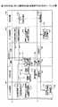
図12,13とともに、図7〜9とともに上述した信号線の切り替えの動作の流れを再度説明する。図12,13中、時刻t0では、データ送信装置100Aおよびデータ受信装置200Aにおいてエラーはなく(ステップS1,S4)、N本の信号線w1〜wNはデータパケットの送信に使用され(ステップS3)、代替信号線wSは制御パケットの送信に使用されている(ステップS2)。The flow of the signal line switching operation described above with reference to FIGS. 12 and 13, at time t0 , there is no error in
ここで時刻t1で、N本の信号線w1〜wNのうちのいずれか(上記同様、信号線w3とする)が故障した場合(ステップS5)を想定する。その場合、当該故障がデータ受信装置200Aの故障検知回路214dで検出され(ステップS6)、当該故障の情報がデータ送信装置100Aに通知される(ステップS7)。データ受信装置200Aでは装置制御回路201の制御下、受信パケットの処理を停止し(ステップS8),データ送信装置100Aでは装置制御回路101の制御下、送信パケットの生成を停止する(ステップS9)。その結果、N本の信号線w1〜wNおよび代替信号線wSは信号の送信には使用されなくなる(ステップS11,S10)。Here, it is assumed thatone of the N signal lines w1 to wN (same as the signal line w3 as described above) fails at time t1 (step S5). In that case, the failure is detected by the
またデータ送信装置100A、データ受信装置200Aのそれぞれの信号線選択指示回路118A,212Aは、故障した信号線w3の使用を停止し、代替信号線を使用するべく指示を出す(ステップS12,S13,S14,S15)。その結果、データ送信装置100のマルチプレクサ116A,119の接続が切り替えられる。その結果、制御パケットの送出先が、送信部117Aから送信部117へと切り替えられる(ステップS16)。また故障した信号線w3に接続されていた送信部117の出力端子が代替信号線wSに接続される。その結果、故障した信号線w3を使用して送信されていた信号を、代替信号線wSを使用して送信することが可能となる(ステップS17,S18)。The
又故障した信号線w3に対応する受信側のマルチプレアクサ213−3、およびマルチプレクサ215Bの接続が切り替えられる。その結果、制御パケットを処理する各パケット処理部217〜219が対応する制御パケットを受け取る元が、受信部214Aから受信部214に切り替えられる。(ステップS19)。また故障した信号線w3に接続されていた受信部214の入力端子が代替信号線wSに接続される。その結果、故障した信号線w3から受信していた信号を、代替信号線wSから受信することが可能となる(ステップS20,S21)。すなわち故障した信号線w3は切り離され、代わりに代替信号線wSが使用可能となる(ステップS22,S23)。The failed signal linew 3 multiplayer AXA the reception side corresponding to 213-3, and the connection of the multiplexer 215B is switched. As a result, the source from which each
ステップS22、S23にて故障した信号線w3は切り離され、代わりに代替信号線wSが使用可能となった時点、すなわち時刻t2にて、装置制御回路101の制御下、以下の動作がなされる。すなわち上記時刻t0における場合同様、データ送信装置100Aの各パケット生成回路111〜114による送信パケットの生成が開始される(ステップS31,S32)。ここでは故障していない(N−1)本の信号線w1、w2,w4〜wNおよび代替信号線wSが信号の送信に使用され(ステップS35,S33)、故障した信号線w3が切り離された状態である(ステップS34)。またデータ受信装置200Aでは、装置制御回路201の制御下、(N−1)本の信号線w1、w2,w4〜wNに代替信号線wSを加えた計N本の信号線により送信されたパケットを受信し、上記時刻t0における場合同様、以下の動作がなされる。すなわち。各パケット処理部216〜219による、受信されたパケットの処理が開始される(ステップS36、S37)。Step S22, S23 signal line w3 failed at is disconnected, when the place of the alternative signal line wS becomes available, i.e. at time t2, the under the control of the
以下に、データ受信装置200Aが信号線の切り替えを検知するための具体的な方法について説明する。ここで信号線の切り替えとは、N本の信号線w1〜wNのうちのいずれかが故障した場合に、故障した信号線(上記例では信号線w3)の代わりに代替信号線wSを使用するように接続の切り替えがなされることをいう。Hereinafter, a specific method for the
データ受信装置200が信号線の切り替えを検知するための具体的な方法としての上記第1の方法は、特殊パケットを用いて通知を行う方法である。当該第1の方法につき図14,図15とともに説明する。 The first method as a specific method for the data receiving apparatus 200 to detect the switching of the signal line is a method of performing notification using a special packet. The first method will be described with reference to FIGS.
ここで特殊パケットとは、「このパケットの次から有効なパケットが転送される」ことを受信部214に通知するためのものである。 Here, the special packet is for notifying the receiving
図14は第1の方法を用いた場合の、データ送信装置100Bおよびデータ受信装置200B中、パケット転送に係るそれぞれの部分を抽出して示す。この場合、データ送信装置100Bには、特殊パケットを生成する特殊パケット生成回路130が設けられ、データ受信装置200Bには特殊パケットを検知する特殊パケット検知回路214sが設けられている。他の部分は図6に示すデータ送信装置100Aおよびデータ受信装置200A中、パケット転送に係るそれぞれの部分と同様であり、重複する説明を省略する。 FIG. 14 shows the respective portions related to packet transfer extracted from the data transmitting apparatus 100B and the data receiving apparatus 200B when the first method is used. In this case, the data transmission device 100B is provided with a special packet generation circuit 130 that generates a special packet, and the data reception device 200B is provided with a special packet detection circuit 214s that detects a special packet. The other parts are the same as the parts related to the packet transfer in the
図15は、上述の図12中、時刻t2にて故障した信号線w3から代替信号線wSへの切り替えのための準備が完了する直前の動作以降の動作の流れを示している。時刻t2にて故障した信号線w3から代替信号線wSへの切り替えのための準備が完了する直前の動作以前の動作は図12、図13ともに上述した動作と同様であり、重複する説明を省略する。FIG. 15 shows the flow of operations after the operation immediately before the preparation for switching from the signal line w3 that failed at time t2 to the alternative signal line wS in FIG. 12 is completed. The operations before the operation immediately before the preparation for switching from the failed signal line w3 to the alternative signal line wS at time t2 are the same as those described above in FIGS. Description is omitted.
データ送信装置100Bにて故障した信号線が代替信号線に切り替わる(ステップS23)と、装置制御回路101の制御下、データ送信装置100Bは、データ受信装置200Bにてパケットを受信し処理し得る状態になるのに要される時間分、待機する(ステップS23A)。その後データ送信装置100Bの特殊パケット生成回路111が特殊パケットを生成し、特殊パケットは他のパケットの送信の場合と同様に、マルチプレクサ116A,送信部117を介し、データ受信装置200Bに送信される(ステップS23B)。この時点でデータ受信装置200Bは既にパケットを受信して処理し得る状態にある。データ受信装置200Bでは、前記特殊パケットが受信部214で受信され特殊パケット検知回路214sで検知されると、装置制御回路201が、次のサイクルから有効なパケットが送信されてくると判断する(S36A)。以後装置制御回路101および201の制御下、故障した信号線以外の(N−1)本の信号線および代替信号線の計N本の信号線により、上記信号線の故障以前の場合同様、データ送信装置100Bとデータ受信装置200Bとの間で、データパケットおよび制御パケットの転送が開始される。 When the failed signal line is switched to the alternative signal line in the data transmission device 100B (step S23), the data transmission device 100B can receive and process the packet in the data reception device 200B under the control of the
データ受信装置が信号線の切り替えを検知するための具体的な方法としての上記第2の方法は、タイマ管理による方法である。当該第2の方法につき図16,図17とともに説明する。 The second method as a specific method for the data receiving device to detect the switching of the signal line is a method based on timer management. The second method will be described with reference to FIGS.
図16は第2の方法を用いた場合の、データ送信装置100Cおよびデータ受信装置200C中、双方間のパケット転送に係るそれぞれの部分を抽出して示す。この場合、データ送信装置100Cにはタイマ140が設けられ、データ受信装置200Bにもタイマ240が設けられている。データ送信装置100Cのタイマ140は信号線選択指示回路118Aに接続され、データ受信装置200Cのタイマ240は信号線選択指示回路212Aに接続される。他の部分は図6に示すデータ送信装置100Aおよびデータ受信装置200A中、双方間のパケット転送に係るそれぞれの部分と同様であり、重複する説明を省略する。 FIG. 16 shows extracted portions of packet transmission between the data transmitting apparatus 100C and the data receiving apparatus 200C when the second method is used. In this case, the data transmission device 100C is provided with a timer 140, and the data reception device 200B is also provided with a timer 240. The timer 140 of the data transmission device 100C is connected to the signal line
図17は、上述の図12中、ステップS12,S14の「故障信号線停止指示」以降の動作の流れを示している。ステップS12,S14の「故障信号線停止指示」以前の動作は図12、図13ともに上述した動作と同様であり、重複する説明を省略する。 FIG. 17 shows a flow of operations after the “failure signal line stop instruction” in steps S12 and S14 in FIG. The operations before the “failure signal line stop instruction” in steps S12 and S14 are the same as the operations described above in both FIG. 12 and FIG.
故障した信号線を代替信号線に切り替えるために「故障信号線停止指示」(ステップS12,S14)および「代替信号線使用指示」(ステップS13,S15)が信号線選択指示回路118A,212Aから出される。同時に信号線選択指示回路118A,212Aはそれぞれタイマ140,240を起動する(ステップS13A,S15A)。各タイマ140,240の設定は、データ送信装置100Cおよびデータ受信装置200Cにて、故障した信号線から代替信号線に切り替えられて、それぞれパケットの生成・送信および受信・処理の再開が可能となるのに要される時間より長い時間が予め設定される。上記故障した信号線から代替信号線への切り替えの動作とは、前記「故障信号線停止指示」(ステップS12,S14)および「代替信号線使用指示」(ステップS13,S15)に応じ各マルチプレクサ116A,119,231−3および215Bのそれぞれの接続が切り替えられる動作をいう。 In order to switch a failed signal line to an alternative signal line, a “failure signal line stop instruction” (steps S12 and S14) and an “alternative signal line use instruction” (steps S13 and S15) are issued from the signal line
各タイマ140,240が前記起動後、前記予め設定された時間を計測し終わる(ステップS13B,15B)と、データ送信装置100Cおよびデータ受信装置200Cのそれぞれの装置制御回路101、201の制御下、以下の動作が行われる。すなわちデータ送信装置100Cでは各パケット生成部111〜114および送信部117等によるパケット生成および送信が再開される(ステップS31,S32)。又データ受信装置200Cでは受信部214および各パケット処理部216〜219等によるパケットの受信および処理が再開される(ステップS36,S37)。ここで上記データ送信装置100Cにおけるパケットの送信の再開によって送信されたパケットが、データ受信装置200Cにおける受信および処理の再開よりも早く受信部214に到達することが無いよう、以下の設定がなされる。すなわち、データ受信装置200Cのタイマ240の設定時間はデータ送信装置100Cのタイマ140よりも短く設定される。以後装置制御回路101および201の制御下、故障した信号線以外の(N−1)本の信号線および代替信号線の計N本の信号線により、上記信号線の故障以前の場合同様、データ送信装置100Cとデータ受信装置200Cとの間で、データパケットおよび制御パケットの転送が開始される。 When the timers 140 and 240 finish measuring the preset time after the activation (steps S13B and 15B), under the control of the
図18は上記第3の方法を用いた場合の、データ送信装置100Dおよびデータ受信装置200D中、双方間のパケット転送に係るそれぞれの部分を抽出して示す。この場合、データ送信装置100Dおよびデータ受信装置200Dの外部に制御用装置300が設けられ、制御用装置300中に設けられた信号線切替管理回路310とデータ送信装置100Dおよびデータ受信装置200Dとが接続される。特に、データ送信装置100Dおよびデータ受信装置200Dの信号線選択指示回路118A,212Aの各々から、上記信号線切替管理回路310に対し接続がなされる。他の部分は図6に示すデータ送信装置100Aおよびデータ受信装置200A中、双方間のパケット転送に係るそれぞれの部分と同様であり、重複する説明を省略する。 FIG. 18 shows the respective parts related to packet transfer between the data transmitting apparatus 100D and the data receiving apparatus 200D when the third method is used. In this case, the
図19は、上述の図12中、ステップS12,S14の「故障信号線停止指示」以降の動作の流れを示している。ステップS12,S14の「故障信号線停止指示」以前の動作は図12、図13ともに上述した動作と同様であり、重複する説明を省略する。 FIG. 19 shows the flow of operations after “failure signal line stop instruction” in steps S12 and S14 in FIG. The operations before the “failure signal line stop instruction” in steps S12 and S14 are the same as the operations described above in both FIG. 12 and FIG.
故障した信号線を代替信号線に切り替えるために「故障信号線停止指示」(ステップS12,S14)および「代替信号線使用指示」(ステップS13,S15)が信号線選択指示回路118A,212Aから出される。同時に信号線選択指示回路118A,212Aは制御用装置300の信号線切替管理回路310に対し、信号線の故障による信号線の切り替えがなされる旨を通知する。同通知を受けた信号線切替管理回路310は以下の動作を行う。すなわち、故障した信号線から代替信号線への切替動作後、データ送信装置100Dおよびデータ受信装置200Dのそれぞれにおいてパケットの生成および送信並びにパケットの受信および処理を再開するタイミングを判断する(ステップS15C,S15D)。前記タイミングの判断は、タイマによる管理或いは信号の監視によって行う。 In order to switch a failed signal line to an alternative signal line, a “failure signal line stop instruction” (steps S12 and S14) and an “alternative signal line use instruction” (steps S13 and S15) are issued from the signal line
上記タイマによる管理の場合、上記第2の方法と同様、上記信号線選択指示回路118A,212Aによる信号線の故障による信号線の切り替えがなされる旨の通知に応じ、信号線切替管理回路310は内部のタイマを起動する(ステップS15C)。当該タイマの設定時間として、データ送信装置100Dおよびデータ受信装置200Dにて、故障した信号線から代替信号線に切り替えられて、それぞれパケットの生成・送信および受信・処理の再開が可能となるのに要される時間より長い時間が予め設定される。上記タイマが前記起動後、前記予め設定された時間を計測し終わると、信号線切替管理回路310はデータ送信装置100Dおよびデータ受信装置200Dのそれぞれの装置制御回路101、201に通知を行う(ステップS15D)。当該通知により、データ送信装置100Dでは装置制御回路101の制御下、各パケット生成部111〜114および送信部117等によるパケット生成および送信が再開される(ステップS31,S32)。又データ受信装置200Dでは装置制御回路201の制御下、受信部214および各パケット処理部216〜219等によるパケットの受信および処理が再開される(ステップS36,S37)。ここで上記データ送信装置100Dにおけるパケットの送信の再開によって送信されたパケットが、データ受信装置200Dにおける受信および処理の再開よりも早く受信部214に到達することが無いようステップS15Dの通知がなされる。すなわち、データ受信装置200Dへの通知はデータ送信装置100Dへの通知よりも早く行われる。以後装置制御回路101および201の制御下、故障した信号線以外の(N−1)本の信号線および代替信号線の計N本の信号線により、上記信号線の故障以前の場合同様、データ送信装置100Dとデータ受信装置200Dとの間で、データパケットおよび制御パケットの転送が開始される。 In the case of management by the timer, as in the second method, the signal line switching management circuit 310 responds to the notification that the signal line is switched due to the failure of the signal line by the signal line
他方前記100D,200Dのそれぞれにおいてパケットの生成および送信並びにパケットの受信および処理を再開するタイミングの判断を信号の監視によっておこなう場合、以下の動作がなされる。すなわち、上記信号線選択指示回路118A,212Aによる信号線の故障による信号線の切り替えがなされる旨の通知以降、信号線切替管理回路310はデータ送信装置100Dおよびデータ受信装置200Dの装置制御回路101、201との間で信号のやりとりを行う。当該信号のやりとりにより、信号線切替管理回路310は、データ送信装置データ100Dおよびデータ受信装置200Dにて、故障した信号線から代替信号線に切り替えられて、各パケットの生成・送信および受信・処理の再開が可能となるタイミングを判断する。当該判断に基づき、信号線切替管理回路310はデータ送信装置100Dおよびデータ受信装置200Dのそれぞれの装置制御回路101、201に通知を行う(ステップS15D)。当該通知により、データ送信装置100Dでは装置制御回路101の制御下、各パケット生成部111〜114および送信部117等によるパケット生成および送信が再開される(ステップS31,S32)。又データ受信装置200Dでは装置制御回路201の制御下、受信部214および各パケット処理部216〜219等によるパケットの受信および処理が再開される(ステップS36,S37)。ここで上記データ送信装置100Dにおけるパケットの送信の再開によって送信されたパケットが、データ受信装置200Dにおける受信および処理の再開よりも早く受信部214に到達することが無いようステップS15Dの通知がなされる。すなわち、データ受信装置200Dへの通知はデータ送信装置100Dへの通知よりも早く行われる。以後装置制御回路101および201の制御下、故障した信号線以外の(N−1)本の信号線および代替信号線の計N本の信号線により、上記信号線の故障以前の場合同様、データ送信装置100Dとデータ受信装置200Dとの間で、データパケットおよび制御パケットの転送が開始される。 On the other hand, when determining the timing for restarting the generation and transmission of packets and the reception and processing of packets in each of the 100D and 200D, the following operations are performed. That is, after the notification that the signal line is switched due to the failure of the signal line by the signal line
以下に図20〜24とともに、上記実施例のデータ送信装置とデータ受信装置との間のパケットの転送で使用される各種パケットについて説明する。 Hereinafter, various packets used in packet transfer between the data transmitting apparatus and the data receiving apparatus of the above embodiment will be described with reference to FIGS.
図20は各種パケットのフォーマットの例を示す。図20に示される如く、パケットは「識別子」、「payload」および「ECC」の、それぞれのフィールドを含む。 FIG. 20 shows examples of various packet formats. As shown in FIG. 20, the packet includes fields of “identifier”, “payload”, and “ECC”.
上記「識別子」のフィールドには、パケットの種類を表す情報が格納される。例えば0000:通常データパケット、0001:フロー制御バケット、0010:割込パケット等の情報が格納される。 In the “identifier” field, information indicating the type of packet is stored. For example, information such as 0000: normal data packet, 0001: flow control bucket, 0010: interrupt packet is stored.
また「payload」、すなわちペイロードのフィールドにはパケットの内容が格納される。ペイロードのフィールドはパケットの種類或いは長さによって長さが異なる。 The contents of the packet are stored in “payload”, that is, the payload field. The length of the payload field varies depending on the type or length of the packet.
また「ECC」のフィールドにはエラーチェックコードが格納される。 An error check code is stored in the “ECC” field.
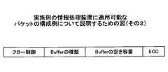
図21はフロー制御パケットのフォーマットの例を示す。フロー制御パケットは、データの転送時や初期化時において、データ受信装置のバッファの空き容量をデータ送信装置に通達するものである。ここでフロー制御の方式、すなわち上記バッファの空き容量の管理の方式として、ビット、バイトによる管理(すなわち1ビットずつ又は1バイトずつ管理する方式)およびクレジットによる管理(すなわち複数バイトを1クレジットとして管理する方式)の2つがある。 FIG. 21 shows an example of the format of the flow control packet. The flow control packet notifies the data transmitting device of the free capacity of the buffer of the data receiving device at the time of data transfer or initialization. Here, the flow control method, that is, the management method of the free space of the buffer, the management by bit and byte (that is, the method that manages one bit or one byte) and the management by credit (that is, the management of plural bytes as one credit) There are two methods.
図21に示す如く、フロー制御パケットは「フロー制御」、「Bufferの種類」、「Bufferの空き容量」、「ECC」の各フィールドを有する。 As shown in FIG. 21, the flow control packet has fields of “flow control”, “buffer type”, “buffer free capacity”, and “ECC”.
「フロー制御パケット」のフィールドにはパケットがフロー制御パケットであることを示す情報が格納される。「Bufferの種類」のフィールドには対象とするバッファが複数有る場合に個々のバッファを識別するための情報が格納される。「Bufferの空き容量」のフィールドには、バッファの空き容量をビット、バイト、クレジット等の各単位で示す情報が格納される。「ECC」のフィールドにはエラーチェックコードが格納される。 Information indicating that the packet is a flow control packet is stored in the “flow control packet” field. The “Buffer type” field stores information for identifying individual buffers when there are a plurality of target buffers. The “Buffer Free Space” field stores information indicating the buffer free space in units such as bits, bytes, and credits. An error check code is stored in the “ECC” field.
次に送達確認パケットについて説明する。データパケットの送信時にデータ送信装置においてシーケンス番号を付加する。そしてデータパケットがデータ受信装置にて正常に受信されたかどうかをデータ送信装置に知らせるため、データ受信装置は、最後に正常に受信されたデータパケットのシーケンス番号を付加した「送達確認パケット」を返送する。 Next, the delivery confirmation packet will be described. The sequence number is added in the data transmission apparatus when transmitting the data packet. Then, in order to inform the data transmission device whether or not the data packet is normally received by the data reception device, the data reception device returns a “delivery confirmation packet” to which the sequence number of the data packet that has been normally received last is added. To do.
送達確認パケットには、データパケットが正常に受信されたことを示す肯定応答(Ack)のパケットおよびエラーにより再送要求を示す否定応答(Nak)のパケットの2種類がある。図22は送達確認パケットのフォーマットの例を、データパケットのフォーマットとの対応関係を示す態様で示す。図22に示される如く、送達確認パケットは、「Ack/Nack」、「AckNack_Seq_Num」、「ECC」の各フィールドを含む。「Ack/Nack」のフィールドには上記肯定応答(Ack)或いは否定応答(Nak)を示す情報が格納される。「AckNack_Seq_Num」のフィールドには受信されたデータパケットが有するシーケンス番号と同じ番号を示す情報が格納される。「ECC」のフィールドにはエラーチェックコードが格納される。 There are two types of delivery confirmation packets: an acknowledgment (Ack) packet indicating that the data packet has been normally received and a negative acknowledgment (Nak) packet indicating a retransmission request due to an error. FIG. 22 shows an example of the format of the delivery confirmation packet in a form showing the correspondence with the format of the data packet. As shown in FIG. 22, the delivery confirmation packet includes fields of “Ack / Nack”, “AckNack_Seq_Num”, and “ECC”. Information indicating the positive response (Ack) or negative response (Nak) is stored in the “Ack / Nack” field. In the “AckNack_Seq_Num” field, information indicating the same number as the sequence number of the received data packet is stored. An error check code is stored in the “ECC” field.
次に割り込みパケットについて説明する。割り込みパケットとは、故障などの予期せぬイベントを原因として、データパケットの転送の間に割り込んで転送される制御パケットである。図23に示す如く、割り込みパケットは、「割込み」、「転送先」、「内容」、「ECC」の各フィールドを含む。「割込み」のフィールドには、割り込みパケットであることを示す情報が格納される。「転送先」のフィールドには、パケットの転送先を示す情報が格納される。「内容」のフィールドには、パケットが通知する上記イベントの内容を示す情報が格納される。「ECC」のフィールドにはエラーチェックコードが格納される。 Next, the interrupt packet will be described. An interrupt packet is a control packet that is interrupted and transferred between data packet transfers due to an unexpected event such as a failure. As shown in FIG. 23, the interrupt packet includes fields of “interrupt”, “transfer destination”, “content”, and “ECC”. Information indicating an interrupt packet is stored in the “interrupt” field. Information indicating the transfer destination of the packet is stored in the “transfer destination” field. In the “content” field, information indicating the contents of the event notified by the packet is stored. An error check code is stored in the “ECC” field.
図24とともに上記送達確認パケットの動作例につき説明する。 An operation example of the delivery confirmation packet will be described with reference to FIG.
図24中、ステップS51〜S53までデータパケットが転送され、データ受信装置にて正常に受信された場合(ステップS54)、データ受信装置はデータ送信装置に対し、肯定応答の送達確認パケットを返送する(ステップS55)。引き続きステップS57〜S59で更にデータパケットが転送され、ステップS58で転送されたパケットがデータ受信装置200に届かなかったとする。データ受信装置200は上記パケットが届かなかったことを検出し(ステップS60、S61)、否定応答の送達確認パケットをデータ送信装置100に返送する(ステップS62)。データ送信装置100では上記届かなかったデータパケットを確認し(ステップS63)、当該データパケット以降を再送する(ステップS64,S65)。 In FIG. 24, when the data packet is transferred from step S51 to S53 and is normally received by the data receiving device (step S54), the data receiving device returns an acknowledgment delivery confirmation packet to the data transmitting device. (Step S55). Subsequently, it is assumed that further data packets are transferred in steps S57 to S59, and the packet transferred in step S58 does not reach the data receiving apparatus 200. The data reception device 200 detects that the packet has not arrived (steps S60 and S61), and returns a negative acknowledgment delivery confirmation packet to the data transmission device 100 (step S62). The
上記実施形態では代替信号線が1本の形態を示したが、変形例として、代替信号線を複数本設ける実施例も可能である。当該変形例では、複数の代替信号線で制御パケットの送受信が可能である。この場合複数の代替信号線に制御パケットを分割して転送させてもよいし、制御パケットの種類に応じて複数の代替信号線に含まれる代替信号線毎に転送するパケットの種類を決めて転送させても良い。 In the above embodiment, one alternative signal line is shown. However, as a modification, an embodiment in which a plurality of alternative signal lines are provided is also possible. In this modification, control packets can be transmitted and received through a plurality of alternative signal lines. In this case, the control packet may be divided and transferred to a plurality of alternative signal lines, or the type of packet to be transferred is determined and transferred for each alternative signal line included in the plurality of alternative signal lines according to the type of the control packet. You may let them.
又上記代替信号線を複数本設ける変形例では、信号線の故障発生時においては、信号線の故障に応じ、故障した信号線を順次代替信号線で代替してゆき、代替信号線の本数を減らす制御を行う。上記の如く代替信号線の本数を減らした結果代替信号線が無くなった時点で、上記実施例中、たとえば図9とともに説明したように、データパケットと制御パケットとが同じ信号線で転送されることになる。 In the modification in which a plurality of alternative signal lines are provided, when a signal line failure occurs, the failed signal lines are sequentially replaced with alternative signal lines in response to the failure of the signal line, and the number of alternative signal lines is reduced. Control to reduce. As described above, when the number of alternative signal lines is reduced and there are no alternative signal lines, the data packet and the control packet are transferred through the same signal line in the above embodiment, for example, as described with reference to FIG. become.
以上の実施例を含む実施形態に関し、更に以下の付記を開示する。
(付記1)
データ本体と、当該データ本体の送受信の制御に係る情報又はその他のイベントを通知するための制御データとを有するデータであって、送信するデータを選択する送信データ選択部と、
前記送信データ選択部で選択されたデータを分割して複数の信号線に送出する送信部と、
前記制御データを、前記複数の信号線に対する代替信号線に送出する代替信号線送信部と、
前記代替信号線の接続を選択する送信信号線選択部とを有するデータ送信装置と、
前記複数の信号線の各々に設けられ、各々が、前記複数の信号線のうち対応する一の信号線と、前記代替信号線とのうちの何れかを選択的に受信部に接続する複数の受信信号線選択部と、
前記複数の受信信号選択部で選択的に接続されたそれぞれの信号線から受信された、分割されたデータを再構成する受信部と、
前記受信部で受信されたデータを振り分ける振り分け部と、
前記代替信号線から受信された制御データを受信する代替信号線受信部と、
前記代替信号線受信部および前記振り分け部のうちのいずれかに選択的に接続する制御データ選択部とを有するデータ受信装置とを有するデータ転送システムであって、
前記複数の信号線の何れもが正常の場合、前記データ送信装置の前記送信データ選択部はデータ本体を選択し、前記送信信号線選択部は前記代替信号線送信部に前記代替信号線を接続し、前記データ受信装置の前記複数の受信信号線選択部はそれぞれ対応する前記複数の信号線に接続し、前記振り分け部は前記受信部で受信されたデータをデータ処理部に振り分け、前記制御データ選択部は前記代替信号線受信部に接続し、
前記複数の信号線のうちの何れかの信号線が故障した場合、前記データ送信装置の前記送信データ選択部はデータ本体および制御データのうちから送信するデータを選択し、前記送信信号線選択部は前記故障した信号線に接続されていた前記送信部の出力端子に前記代替信号線を接続し、前記データ受信装置の前記複数の受信信号線選択部のうち、前記故障した信号線に対応する受信信号線選択部は前記代替信号線に接続し、前記故障した信号線以外の全ての信号線のそれぞれに対応するそれぞれの受信信号線選択部は対応するそれぞれの信号線に接続し、前記振り分け部は前記受信部で受信されたデータをデータ処理部および制御データ選択部に振り分け、前記制御データ選択部は前記振り分け部に接続することを特徴とするデータ転送システム。
(付記2)
前記複数の信号線のうちのいずれかの信号線が故障した場合に、前記データ送信装置の前記送信データ選択部がデータ本体および制御データのうちから送信するデータを選択し、前記送信信号線選択部が前記故障した信号線に接続されていた前記送信部の出力端子に前記代替信号線を接続することによって、前記故障した信号線以外の信号線および前記代替信号線を使用したデータの送信を開始する際に、特殊データをデータ受信装置に送信し、
前記データ受信装置では、前記複数の受信信号線選択部のうち前記故障した信号線に対応する受信信号線選択部が前記代替信号線に接続し、前記故障した信号線以外の全ての信号線のそれぞれに対応するそれぞれの受信信号線選択部が対応するそれぞれの信号線に接続し、前記振り分け部が前記受信部で受信されたデータをデータ処理部および制御データ選択部に振り分け、前記制御データ選択部が前記振り分け部に接続することによって、前記故障した信号線以外の信号線および前記代替信号線を使用してデータを受信する際、前記特殊データの受信により、データの送信が開始されることを認識することを特徴とする付記1に記載のデータ転送システム。
(付記3)
前記複数の信号線のうちのいずれかの信号線が故障した場合に、前記データ送信装置の前記送信データ選択部がデータ本体および制御データのうちから送信するデータを選択し、前記送信信号線選択部が前記故障した信号線に接続されていた前記送信部の出力端子に前記代替信号線を接続することによって、前記故障した信号線以外の信号線および前記代替信号線を使用したデータの送信を開始する際に、前記信号線の故障の時点から、前記故障した信号線以外の信号線および前記代替信号線を使用した送信を開始する迄の時間を送信側のタイマで測定し、
前記データ受信装置の前記複数の受信信号線選択部のうち前記故障した信号線に対応する受信信号線選択部が前記代替信号線に接続し、前記故障した信号線以外の全ての信号線のそれぞれに対応するそれぞれの受信信号線選択部が対応するそれぞれの信号線に接続し、前記振り分け部が前記受信部で受信されたデータをデータ処理部および制御データ選択部に振り分け、前記制御データ選択部が前記振り分け部に接続することによって、前記故障した信号線以外の信号線および前記代替信号線を使用してデータを受信する際、前記信号線の故障の時点から、データが前記故障した信号線以外の信号線および前記代替信号線を使用して送信される迄の時間を受信側のタイマで測定することにより、データの送信が開始されることを認識することを特徴とする付記1に記載のデータ転送システム。
(付記4)
前記複数の信号線のうちのいずれかの信号線が故障した場合に、前記データ送信装置の前記送信データ選択部がデータ本体および制御データのうちから送信するデータを選択し、前記送信信号線選択部が前記故障した信号線に接続されていた前記送信部の出力端子に前記代替信号線を接続することによって、前記故障した信号線以外の信号線および前記代替信号線を使用して実際にデータを送信する際に、外部の制御装置からの通知により、前記故障した信号線以外の信号線および前記代替信号線を使用して送信を開始し、
前記データ受信装置の前記複数の受信信号線選択部のうち前記故障した信号線に対応する受信信号線選択部が前記代替信号線に接続し、前記故障した信号線以外の全ての信号線のそれぞれに対応するそれぞれの受信信号線選択部が対応するそれぞれの信号線に接続し、前記振り分け部が前記受信部で受信されたデータをデータ処理部および制御データ選択部に振り分け、前記制御データ選択部が前記振り分け部に接続することによって、前記故障した信号線以外の信号線および前記代替信号線を使用してデータを受信する際、前記外部の制御装置からの通知により、データの送信の開始を認識することを特徴とする付記1に記載のデータ転送システム。
(付記5)
データ本体と、当該データ本体の送受信の制御に係る情報又はその他のイベントの通知を行うための制御データとを有するデータであって、送信するデータを選択する送信データ選択部と、
前記送信データ選択部で選択されたデータを分割して複数の信号線に送出する送信部と、
前記制御データを、前記複数の信号線に対する代替信号線に送出する代替信号線送信部と、
前記代替信号線の接続を選択する送信信号線選択部とを有するデータ転送装置であって、
前記複数の信号線の何れもが正常の場合、前記送信データ選択部はデータ本体を選択し、前記送信信号線選択部は前記代替信号線送信部に前記代替信号線を接続し、
前記複数の信号線のうちの何れかの信号線が故障した場合、前記送信データ選択部はデータ本体および制御データのうちから送信するデータを選択し、前記送信信号線選択部は前記故障した信号線が接続されていた前記送信部の出力端子に前記代替信号線を接続することを特徴とするデータ転送装置。
(付記6)
前記複数の信号線のうちのいずれかの信号線が故障した場合に、前記送信データ選択部がデータ本体および制御データのうちから送信するデータを選択し、前記送信信号線選択部が前記故障した信号線に接続されていた前記送信部の出力端子に前記代替信号線を接続することによって前記故障した信号線以外の信号線および前記代替信号線を使用したデータの送信を開始する際に、特殊データをデータ受信装置に送信することを特徴とする付記5に記載のデータ転送装置。
(付記7)
前記複数の信号線のうちのいずれかの信号線が故障した場合に、前記送信データ選択部がデータ本体および制御データのうちから送信するデータを選択し、前記送信信号線選択部が前記故障した信号線に接続されていた前記送信部の出力端子に前記代替信号線を接続することによって前記故障した信号線以外の信号線および前記代替信号線を使用したデータの送信を開始する際に、前記信号線の故障の時点から、データを前記故障した信号線以外の信号線および前記代替信号線を使用した送信を開始する迄の時間をタイマで測定することを特徴とする付記5に記載のデータ転送装置。
(付記8)
前記複数の信号線のうちのいずれかの信号線が故障した場合に、前記送信データ選択部がデータ本体および制御データのうちから送信するデータを選択し、前記送信信号線選択部が前記故障した信号線に接続されていた前記送信部の出力端子に前記代替信号線を接続することによって前記故障した信号線以外の信号線および前記代替信号線を使用して実際にデータを送信する際に、外部の制御装置からの通知により、前記故障した信号線以外の信号線および前記代替信号線を使用して送信を開始することを特徴とする付記5に記載のデータ転送装置。
(付記9)
前記複数の信号線の各々に設けられ、各々が、前記複数の信号線のうち対応する一の信号線と、前記代替信号線とのうちの何れかを選択的に受信部に接続する複数の受信信号線選択部と、
前記複数の受信信号選択部で選択的に接続されたそれぞれの信号線から受信された、分割されたデータを再構成する受信部と、
前記受信部で受信されたデータを振り分ける振り分け部と、
前記代替信号線から受信された制御データを受信する代替信号線受信部と、
前記代替信号線受信部および前記振り分け部のうちのいずれかに選択的に接続する制御データ選択部とを有するデータ転送装置であって、
前記複数の信号線の何れもが正常の場合、前記複数の受信信号線選択部はそれぞれ対応する前記複数の信号線に接続し、前記振り分け部は前記受信部で受信されたデータをデータ処理部に振り分け、前記制御データ選択部は前記代替信号線受信部に接続し、
前記複数の信号線のうちの何れかの信号線が故障した場合、前記複数の受信信号線選択部のうち、前記故障した信号線に対応する受信信号線選択部は前記代替信号線に接続し、前記故障した信号線以外の全ての信号線のそれぞれに対応するそれぞれの受信信号線選択部は対応するそれぞれの信号線に接続し、前記振り分け部は前記受信部で受信されたデータをデータ処理部および制御データ選択部に振り分け、前記制御データ選択部は前記振り分け部に接続することを特徴とするデータ転送装置。
(付記10)
前記複数の信号線のうちのいずれかの信号線が故障した場合に、前記複数の受信信号線選択部のうち前記故障した信号線に対応する受信信号線選択部が前記代替信号線に接続し、前記故障した信号線以外の全ての信号線のそれぞれに対応するそれぞれの受信信号線選択部が対応するそれぞれの信号線に接続し、前記振り分け部が前記受信部で受信されたデータをデータ処理部および制御データ選択部に振り分け、前記制御データ選択部が前記振り分け部に接続することによって、前記故障した信号線以外の信号線および前記代替信号線を使用してデータを受信する際、前記特殊データの受信により、データの送信が開始されることを認識することを特徴とする付記9に記載のデータ転送装置。
(付記11)
前記複数の信号線のうちのいずれかの信号線が故障した場合に、前記複数の受信信号線選択部のうち前記故障した信号線に対応する受信信号線選択部が前記代替信号線に接続し、前記故障した信号線以外の全ての信号線のそれぞれに対応するそれぞれの受信信号線選択部が対応するそれぞれの信号線に接続し、前記振り分け部が前記受信部で受信されたデータをデータ処理部および制御データ選択部に振り分け、前記制御データ選択部が前記振り分け部に接続することによって、前記故障した信号線以外の信号線および前記代替信号線を使用してデータを受信する際、前記信号線の故障の時点から、前記故障した信号線以外の信号線および前記代替信号線を使用して送信される迄の時間をタイマで測定することにより、データの送信が開始されることを認識することを特徴とする付記9に記載のデータ転送装置。
(付記12)
前記複数の信号線のうちのいずれかの信号線が故障した場合に、前記複数の受信信号線選択部のうち前記故障した信号線に対応する受信信号線選択部が前記代替信号線に接続し、前記故障した信号線以外の全ての信号線のそれぞれに対応するそれぞれの受信信号線選択部が対応するそれぞれの信号線に接続し、前記振り分け部が前記受信部で受信されたデータをデータ処理部および制御データ選択部に振り分け、前記制御データ選択部が前記振り分け部に接続することによって、前記故障した信号線以外の信号線および前記代替信号線を使用してデータを受信する際、外部の制御装置からの通知により、データの送信の開始を認識することを特徴とする付記9に記載のデータ転送装置。
(付記13)
データ送信装置が、データ本体と、当該データ本体の送受信の制御に係る情報又はその他のイベントを通知するための制御データとを有するデータであって、送信するデータを選択する送信データ選択段階と、
前記送信データ選択段階で選択されたデータを分割して複数の信号線に送出する送信段階と、
前記複数の信号線に対する代替信号線の接続を選択する送信信号線選択段階とを実行し、
データ受信装置が、前記複数の信号線の各々につき、当該一の信号線と、前記代替信号線とのうちの何れかを選択する複数の受信信号線選択段階と、
前記複数の受信信号選択段階のそれぞれで選択されたそれぞれの信号線から受信された、分割されたデータを再構成する受信段階と、
前記受信段階で受信されたデータを振り分ける振り分け段階と、
前記代替信号線から受信された制御データを受信する代替信号線受信段階とを実行し、
前記複数の信号線の何れもが正常の場合、前記データ送信装置の前記送信データ選択段階ではデータ本体を選択し、前記送信信号線選択段階では制御データを前記代替信号線に送出し、
前記データ受信装置の前記複数の受信信号線選択段階では前記複数の信号線のそれぞれを選択し、前記振り分け段階では前記受信段階で受信されたデータをデータ処理部に振り分け、前記代替信号線受信段階で受信された信号を制御データ処理部に渡し、
前記複数の信号線のうちの何れかの信号線が故障した場合、前記データ送信装置の前記送信データ選択段階ではデータ本体および制御データのうちから送信するデータを選択し、前記送信信号線選択段階では前記故障した信号線が接続されていた前記送信部の出力端子に前記代替信号線を接続し、
前記データ受信装置の前記複数の受信信号線選択段階では、前記故障した信号線に対応する受信信号線選択段階では前記代替信号線を選択し、前記故障した信号線以外の全ての信号線のそれぞれに対応する受信信号線選択段階では対応するそれぞれの信号線を選択し、前記振り分け段階では前記受信段階で受信されたデータをデータ処理部および制御データ処理部に振り分けることを特徴とするデータ転送方法。
(付記14)
前記複数の信号線のうちの何れかの信号線が故障した場合、前記データ送信装置の前記送信データ選択段階でデータ本体および制御データのうちから送信するデータを選択し、前記送信信号線選択段階で前記故障した信号線が接続されていた前記送信部の出力端子に前記代替信号線を接続して、前記故障した信号線以外の信号線および前記代替信号線を使用したデータの送信を開始する際に、特殊データをデータ受信装置に送信し、
前記データ受信装置の前記複数の受信信号線選択段階で前記故障した信号線に対応する受信信号線選択段階で前記代替信号線を選択し、前記故障した信号線以外の全ての信号線のそれぞれに対応する受信信号線選択段階で対応するそれぞれの信号線を選択し、前記振り分け段階で、前記受信段階で受信されたデータをデータ処理部および制御データ処理部に振り分けることで、前記故障した信号線以外の信号線および前記代替信号線を使用してデータを受信する際、前記特殊データの受信により、データの送信が開始されることを認識することを特徴とする付記13に記載のデータ転送方法。
(付記15)
前記複数の信号線のうちの何れかの信号線が故障した場合、前記データ送信装置の前記送信データ選択段階でデータ本体および制御データのうちから送信するデータを選択し、前記送信信号線選択段階で前記故障した信号線が接続されていた前記送信部の出力端子に前記代替信号線を接続して、前記故障した信号線以外の信号線および前記代替信号線を使用したデータの送信を開始する際に、前記信号線の故障の時点から、前記故障した信号線以外の信号線および前記代替信号線を使用した送信を開始する迄の時間を送信側のタイマで測定し、
前記データ受信装置の前記複数の受信信号線選択段階で前記故障した信号線に対応する受信信号線選択段階では前記代替信号線を選択し、前記故障した信号線以外の全ての信号線のそれぞれに対応するそれぞれの受信信号線選択段階で対応するそれぞれの信号線を選択し、前記振り分け段階で、前記受信段階で受信されたデータをデータ処理部および制御データ処理部に振り分けることで、前記故障した信号線以外の信号線および前記代替信号線を使用してデータを受信する際、前記信号線の故障の時点から、前記故障した信号線以外の信号線および前記代替信号線を使用して送信が開始される迄の時間を受信側のタイマで測定することにより、データの送信が開始されることを認識することを特徴とする付記13に記載のデータ転送方法。
(付記16)
前記複数の信号線のうちの何れかの信号線が故障した場合、前記データ送信装置の前記送信データ選択でデータ本体および制御データのうちから送信するデータを選択し、前記送信信号線選択段階で前記故障した信号線が接続されていた前記送信部の出力端子に前記代替信号線を接続して、前記故障した信号線以外の信号線および前記代替信号線を使用したデータの送信を開始する際に、外部の制御装置からの通知により、実際に前記故障した信号線以外の信号線および前記代替信号線を使用して送信を開始し、
前記データ受信装置の前記複数の受信信号線選択段階で前記故障した信号線に対応する受信信号線選択段階では前記代替信号線を選択し、前記故障した信号線以外の全ての信号線のそれぞれに対応するそれぞれの受信信号線選択段階で対応するそれぞれの信号線を選択し、前記振り分け段階で、前記受信段階で受信されたデータをデータ処理部および制御データ処理部に振り分けることで、前記故障した信号線以外の信号線および前記代替信号線を使用してデータを受信する際、前記外部の制御装置からの通知により、データの送信の開始を認識することを特徴とする付記13に記載のデータ転送方法。The following additional notes are further disclosed with respect to the embodiment including the above examples.
(Appendix 1)
A transmission data selection unit for selecting data to be transmitted, which is data having a data body and control data for notifying information or other events related to transmission / reception control of the data body;
A transmission unit for dividing the data selected by the transmission data selection unit and sending it to a plurality of signal lines;
An alternative signal line transmitter that transmits the control data to an alternative signal line for the plurality of signal lines;
A data transmission device having a transmission signal line selection unit for selecting connection of the alternative signal line;
A plurality of signal lines that are provided on each of the plurality of signal lines, each of which selectively connects one of the plurality of signal lines and the alternative signal line to the receiving unit; A reception signal line selector;
A receiving unit for reconfiguring the divided data received from each signal line selectively connected by the plurality of received signal selecting units;
A distribution unit that distributes data received by the reception unit;
An alternative signal line receiver for receiving control data received from the alternative signal line;
A data transfer system having a data reception device having a control data selection unit selectively connected to any of the alternative signal line reception unit and the distribution unit,
When all of the plurality of signal lines are normal, the transmission data selection unit of the data transmission apparatus selects a data body, and the transmission signal line selection unit connects the substitution signal line to the substitution signal line transmission unit. The plurality of reception signal line selection units of the data receiving device are connected to the corresponding signal lines, respectively, and the distribution unit distributes data received by the reception unit to a data processing unit, and the control data The selector is connected to the alternative signal line receiver,
When any one of the plurality of signal lines fails, the transmission data selection unit of the data transmission device selects data to be transmitted from the data body and control data, and the transmission signal line selection unit Connects the alternative signal line to the output terminal of the transmission unit connected to the failed signal line, and corresponds to the failed signal line among the plurality of reception signal line selection units of the data reception device The reception signal line selection unit is connected to the substitute signal line, and each reception signal line selection unit corresponding to each of all the signal lines other than the failed signal line is connected to the corresponding signal line, and the distribution is performed. A data transfer system characterized in that the data distribution unit distributes the data received by the reception unit to a data processing unit and a control data selection unit, and the control data selection unit is connected to the distribution unit. Temu.
(Appendix 2)
When any one of the plurality of signal lines fails, the transmission data selection unit of the data transmission device selects data to be transmitted from the data body and control data, and the transmission signal line selection By connecting the alternative signal line to the output terminal of the transmitting unit that has been connected to the failed signal line, data transmission using a signal line other than the failed signal line and the alternative signal line is performed. When starting, send special data to the data receiver,
In the data reception device, a reception signal line selection unit corresponding to the failed signal line among the plurality of reception signal line selection units is connected to the alternative signal line, and all of the signal lines other than the failed signal line are connected. Each corresponding reception signal line selection unit is connected to each corresponding signal line, and the distribution unit distributes the data received by the reception unit to a data processing unit and a control data selection unit, and the control data selection When the data is received using the signal line other than the failed signal line and the alternative signal line by connecting the unit to the distribution unit, data transmission is started by receiving the special data. The data transfer system according to
(Appendix 3)
When any one of the plurality of signal lines fails, the transmission data selection unit of the data transmission device selects data to be transmitted from the data body and control data, and the transmission signal line selection By connecting the alternative signal line to the output terminal of the transmitting unit that has been connected to the failed signal line, data transmission using a signal line other than the failed signal line and the alternative signal line is performed. When starting, measure the time from the time of the failure of the signal line to the start of transmission using a signal line other than the failed signal line and the alternative signal line with a timer on the transmission side,
A reception signal line selection unit corresponding to the failed signal line among the plurality of reception signal line selection units of the data reception device is connected to the alternative signal line, and each of all the signal lines other than the failed signal line Each of the reception signal line selection units corresponding to the signal line is connected to the corresponding signal line, and the distribution unit distributes the data received by the reception unit to a data processing unit and a control data selection unit, and the control data selection unit When the data is received using the signal line other than the failed signal line and the alternative signal line by connecting to the distribution unit, the data from the time of the failure of the signal line is the data of the failed signal line. Recognize that data transmission is started by measuring the time until transmission using the other signal line and the alternative signal line with a timer on the receiving side. Data transfer system according to
(Appendix 4)
When any one of the plurality of signal lines fails, the transmission data selection unit of the data transmission device selects data to be transmitted from the data body and control data, and the transmission signal line selection By connecting the alternative signal line to the output terminal of the transmitting unit, where the unit was connected to the failed signal line, data is actually transmitted using a signal line other than the failed signal line and the alternative signal line. , By using a signal line other than the failed signal line and the alternative signal line, in response to a notification from an external control device,
A reception signal line selection unit corresponding to the failed signal line among the plurality of reception signal line selection units of the data reception device is connected to the alternative signal line, and each of all the signal lines other than the failed signal line Each of the reception signal line selection units corresponding to the signal line is connected to the corresponding signal line, and the distribution unit distributes the data received by the reception unit to a data processing unit and a control data selection unit, and the control data selection unit By connecting to the distribution unit, when receiving data using a signal line other than the failed signal line and the alternative signal line, the transmission of data is started by a notification from the external control device. The data transfer system according to
(Appendix 5)
A transmission data selection unit for selecting data to be transmitted, which is data having a data body and control data for notifying information related to transmission / reception control of the data body or other events;
A transmission unit for dividing the data selected by the transmission data selection unit and sending it to a plurality of signal lines;
An alternative signal line transmitter that transmits the control data to an alternative signal line for the plurality of signal lines;
A data transfer device having a transmission signal line selection unit for selecting connection of the alternative signal line,
When all of the plurality of signal lines are normal, the transmission data selection unit selects a data body, the transmission signal line selection unit connects the substitution signal line to the substitution signal line transmission unit,
When any one of the plurality of signal lines fails, the transmission data selection unit selects data to be transmitted from the data body and control data, and the transmission signal line selection unit selects the failed signal. A data transfer apparatus, wherein the alternative signal line is connected to an output terminal of the transmitting unit to which a line is connected.
(Appendix 6)
When any one of the plurality of signal lines fails, the transmission data selection unit selects data to be transmitted from the data body and control data, and the transmission signal line selection unit fails. When starting transmission of data using a signal line other than the failed signal line and the alternative signal line by connecting the alternative signal line to the output terminal of the transmission unit connected to the signal line, The data transfer device according to
(Appendix 7)
When any one of the plurality of signal lines fails, the transmission data selection unit selects data to be transmitted from the data body and control data, and the transmission signal line selection unit fails. When starting transmission of data using a signal line other than the failed signal line and the alternative signal line by connecting the alternative signal line to the output terminal of the transmission unit connected to the signal line, 6. The data according to
(Appendix 8)
When any one of the plurality of signal lines fails, the transmission data selection unit selects data to be transmitted from the data body and control data, and the transmission signal line selection unit fails. When actually transmitting data using a signal line other than the failed signal line and the alternative signal line by connecting the alternative signal line to the output terminal of the transmission unit connected to the signal line, 6. The data transfer device according to
(Appendix 9)
A plurality of signal lines that are provided on each of the plurality of signal lines, each of which selectively connects one of the plurality of signal lines and the alternative signal line to the receiving unit; A reception signal line selector;
A receiving unit for reconfiguring the divided data received from each signal line selectively connected by the plurality of received signal selecting units;
A distribution unit that distributes data received by the reception unit;
An alternative signal line receiver for receiving control data received from the alternative signal line;
A data transfer device having a control data selection unit selectively connected to any of the alternative signal line reception unit and the distribution unit;
When all of the plurality of signal lines are normal, the plurality of reception signal line selection units are connected to the corresponding signal lines, respectively, and the distribution unit is a data processing unit that receives data received by the reception unit The control data selection unit is connected to the alternative signal line receiving unit,
When any one of the plurality of signal lines fails, the reception signal line selection unit corresponding to the failed signal line among the plurality of reception signal line selection units is connected to the substitute signal line. The reception signal line selection unit corresponding to each of all the signal lines other than the failed signal line is connected to the corresponding signal line, and the distribution unit performs data processing on the data received by the reception unit. And a control data selection unit, and the control data selection unit is connected to the distribution unit.
(Appendix 10)
When any one of the plurality of signal lines fails, a reception signal line selection unit corresponding to the failed signal line among the plurality of reception signal line selection units is connected to the substitute signal line. The reception signal line selection unit corresponding to each of all the signal lines other than the failed signal line is connected to the corresponding signal line, and the distribution unit performs data processing on the data received by the reception unit When the data is received using the signal line other than the failed signal line and the alternative signal line by the distribution to the distribution unit and the control data selection unit, and the control data selection unit is connected to the distribution unit. The data transfer apparatus according to appendix 9, wherein the data transmission recognizes that data transmission is started.
(Appendix 11)
When any one of the plurality of signal lines fails, a reception signal line selection unit corresponding to the failed signal line among the plurality of reception signal line selection units is connected to the substitute signal line. The reception signal line selection unit corresponding to each of all the signal lines other than the failed signal line is connected to the corresponding signal line, and the distribution unit performs data processing on the data received by the reception unit And the control data selection unit connected to the distribution unit, so that when the signal is received using the signal line other than the failed signal line and the alternative signal line, the signal Data transmission is started by measuring with a timer the time from the time of the line failure until it is transmitted using a signal line other than the failed signal line and the alternative signal line. Data transfer apparatus according to Note 9, characterized in that to recognize Rukoto.
(Appendix 12)
When any one of the plurality of signal lines fails, a reception signal line selection unit corresponding to the failed signal line among the plurality of reception signal line selection units is connected to the substitute signal line. The reception signal line selection unit corresponding to each of all the signal lines other than the failed signal line is connected to the corresponding signal line, and the distribution unit performs data processing on the data received by the reception unit When the data is received using the signal line other than the failed signal line and the alternative signal line by the distribution to the distribution unit and the control data selection unit, the control data selection unit is connected to the distribution unit. The data transfer device according to appendix 9, wherein the start of data transmission is recognized by a notification from the control device.
(Appendix 13)
A data transmission device is data having a data body and control data for notifying information related to control of transmission / reception of the data body or other events, and a transmission data selection stage for selecting data to be transmitted;
A transmission step of dividing the data selected in the transmission data selection step and sending it to a plurality of signal lines;
Performing a transmission signal line selection step of selecting connection of alternative signal lines to the plurality of signal lines;
A plurality of reception signal line selection steps in which the data reception device selects one of the one signal line and the alternative signal line for each of the plurality of signal lines;
A receiving step of reconstructing the divided data received from each signal line selected in each of the plurality of received signal selection steps;
A distribution step of distributing the data received in the reception step;
Performing an alternative signal line receiving step of receiving control data received from the alternative signal line;
When all of the plurality of signal lines are normal, a data body is selected in the transmission data selection stage of the data transmission device, and control data is sent to the alternative signal line in the transmission signal line selection stage.
The plurality of reception signal line selection steps of the data reception device select each of the plurality of signal lines, and in the distribution step, the data received in the reception step is distributed to a data processing unit, and the alternative signal line reception step Pass the signal received at the control data processing unit,
When any one of the plurality of signal lines fails, the transmission data selection step of the data transmission device selects data to be transmitted from the data body and control data, and the transmission signal line selection step Then, the alternative signal line is connected to the output terminal of the transmission unit to which the failed signal line was connected,
In the plurality of reception signal line selection steps of the data receiving device, the alternative signal line is selected in the reception signal line selection step corresponding to the failed signal line, and each of all signal lines other than the failed signal line is selected. A data transfer method comprising: selecting a corresponding signal line in a reception signal line selection step corresponding to the step; and distributing data received in the reception step to a data processing unit and a control data processing unit in the distribution step .
(Appendix 14)
When any one of the plurality of signal lines fails, the data transmission apparatus selects the data to be transmitted from the data body and the control data in the transmission data selection stage, and the transmission signal line selection stage. The substitute signal line is connected to the output terminal of the transmitting unit to which the faulty signal line was connected, and data transmission using the signal line other than the faulty signal line and the substitute signal line is started. When sending special data to the data receiver,
The alternative signal line is selected in a reception signal line selection step corresponding to the failed signal line in the plurality of reception signal line selection steps of the data reception device, and each of all signal lines other than the failed signal line is selected. The corresponding signal line is selected in the corresponding reception signal line selection stage, and the data line received in the reception stage is distributed to the data processing unit and the control data processing unit in the distribution stage, whereby the failed
(Appendix 15)
When any one of the plurality of signal lines fails, the data transmission apparatus selects the data to be transmitted from the data body and the control data in the transmission data selection stage, and the transmission signal line selection stage. The substitute signal line is connected to the output terminal of the transmitting unit to which the faulty signal line was connected, and data transmission using the signal line other than the faulty signal line and the substitute signal line is started. In this case, the time from the time of the failure of the signal line to the start of transmission using the signal line other than the failed signal line and the alternative signal line is measured with a timer on the transmission side,
In the reception signal line selection step corresponding to the failed signal line in the plurality of reception signal line selection steps of the data reception device, the substitute signal line is selected, and each of all signal lines other than the failed signal line is selected. Each corresponding signal line is selected in each corresponding reception signal line selection step, and the data received in the reception step is distributed to the data processing unit and the control data processing unit in the distribution step. When receiving data using a signal line other than a signal line and the substitute signal line, transmission is performed using the signal line other than the failed signal line and the substitute signal line from the time of failure of the signal line. 14. The data transfer method according to
(Appendix 16)
When any one of the plurality of signal lines fails, the transmission data selection of the data transmission device selects data to be transmitted from the data body and control data, and in the transmission signal line selection step When the alternative signal line is connected to the output terminal of the transmission unit to which the failed signal line was connected, and transmission of data using the signal line other than the failed signal line and the alternative signal line is started. In addition, according to a notification from an external control device, transmission is started using a signal line other than the actually failed signal line and the alternative signal line,
In the reception signal line selection step corresponding to the failed signal line in the plurality of reception signal line selection steps of the data reception device, the substitute signal line is selected, and each of all signal lines other than the failed signal line is selected. Each corresponding signal line is selected in each corresponding reception signal line selection step, and the data received in the reception step is distributed to the data processing unit and the control data processing unit in the distribution step. 14. The data according to
100A,100B,100C,100D データ送信装置
115A 送信パケット選択回路
116A マルチプレクサ
116B マルチプレクサ
116C 制御パケット送信選択回路
117 送信部
118A 信号線選択指示回路
119 マルチプレクサ
130 特殊パケット生成回路
140 タイマ
120−1〜120−N、121 送信バッファ
200A,200B,200C,200D データ受信装置
210−1〜210−N、211 受信バッファ
212A 信号線選択指示回路
213−1〜213−N マルチプレクサ
214 受信部
214d 故障検知回路
214s 特殊パケット検知回路
214A 受信部
215A デマルチプレクサ
215B マルチプレクサ
215C デマルチプレクサ
240 タイマ
300 制御用回路
310 信号線切替管理回路100A, 100B, 100C, 100D
Claims (10)
Translated fromJapanese前記送信データ選択部が選択したデータを分割して複数の信号線に送出する送信部と、
前記制御データを、前記複数の信号線に対する代替信号線に送出する代替信号線送信部と、
前記代替信号線の接続を選択する送信信号線選択部とを有するデータ送信装置と、
前記複数の信号線の各々に設けられ、各々が、前記複数の信号線のうち対応する一の信号線と、前記代替信号線とのうちの何れかを選択的に受信部に接続する複数の受信信号線選択部と、
前記複数の受信信号選択部で選択的に接続されたそれぞれの信号線から受信された、分割されたデータを再構成する受信部と、
前記受信部で受信されたデータを振り分ける振り分け部と、
前記代替信号線から受信された制御データを受信する代替信号線受信部と、
前記代替信号線受信部および前記振り分け部のうちのいずれか選択的に接続する制御データ選択部とを有するデータ受信装置とを有するデータ転送システムであって、
前記複数の信号線の何れもが正常の場合、前記データ送信装置の前記送信データ選択部はデータ本体を選択し、前記送信信号線選択部は前記代替信号線送信部に前記代替信号線を接続し、前記データ受信装置の前記複数の受信信号線選択部はそれぞれ対応する前記複数の信号線に接続し、前記振り分け部は前記受信部で受信されたデータをデータ処理部に振り分け、前記制御データ選択部は前記代替信号線受信部に接続し、
前記複数の信号線のうちの何れかの信号線が故障した場合、前記データ送信装置の前記送信データ選択部はデータ本体および制御データのうちから送信するデータを選択し、前記送信信号線選択部は前記故障した信号線に接続されていた前記送信部の出力端子に前記代替信号線を接続し、前記データ受信装置の前記複数の受信信号線選択部のうち、前記故障した信号線に対応する受信信号線選択部は前記代替信号線に接続し、前記故障した信号線以外の全ての信号線のそれぞれに対応するそれぞれの受信信号線選択部は対応するそれぞれの信号線に接続し、前記振り分け部は前記受信部で受信されたデータをデータ処理部および制御データ選択部に振り分け、前記制御データ選択部は前記振り分け部に接続することを特徴とするデータ転送システム。A transmission data selection unit for selecting data to be transmitted, which is data having a data body and control data for notifying information or other events related to transmission / reception control of the data body;
A transmission unit that divides the data selected by the transmission data selection unit and sends it to a plurality of signal lines;
An alternative signal line transmitter that transmits the control data to an alternative signal line for the plurality of signal lines;
A data transmission device having a transmission signal line selection unit for selecting connection of the alternative signal line;
A plurality of signal lines that are provided on each of the plurality of signal lines, each of which selectively connects one of the plurality of signal lines and the alternative signal line to the receiving unit; A reception signal line selector;
A receiving unit for reconfiguring the divided data received from each signal line selectively connected by the plurality of received signal selecting units;
A distribution unit that distributes data received by the reception unit;
An alternative signal line receiver for receiving control data received from the alternative signal line;
A data transfer system having a data reception device having a control data selection unit selectively connected to either the alternative signal line reception unit or the distribution unit,
When all of the plurality of signal lines are normal, the transmission data selection unit of the data transmission apparatus selects a data body, and the transmission signal line selection unit connects the substitution signal line to the substitution signal line transmission unit. The plurality of reception signal line selection units of the data receiving device are connected to the corresponding signal lines, respectively, and the distribution unit distributes data received by the reception unit to a data processing unit, and the control data The selector is connected to the alternative signal line receiver,
When any one of the plurality of signal lines fails, the transmission data selection unit of the data transmission device selects data to be transmitted from the data body and control data, and the transmission signal line selection unit Connects the alternative signal line to the output terminal of the transmission unit connected to the failed signal line, and corresponds to the failed signal line among the plurality of reception signal line selection units of the data reception device The reception signal line selection unit is connected to the substitute signal line, and each reception signal line selection unit corresponding to each of all the signal lines other than the failed signal line is connected to the corresponding signal line, and the distribution is performed. A data transfer system characterized in that the data distribution unit distributes the data received by the reception unit to a data processing unit and a control data selection unit, and the control data selection unit is connected to the distribution unit. Temu.
前記データ受信装置では、前記複数の受信信号線選択部のうち前記故障した信号線に対応する受信信号線選択部が前記代替信号線に接続し、前記故障した信号線以外の全ての信号線のそれぞれに対応するそれぞれの受信信号線選択部が対応するそれぞれの信号線に接続し、前記振り分け部が前記受信部で受信されたデータをデータ処理部および制御データ選択部に振り分け、前記制御データ選択部が前記振り分け部に接続することによって、前記故障した信号線以外の信号線および前記代替信号線を使用してデータを受信する際、前記特殊データの受信により、データの送信が開始されることを認識することを特徴とする請求項1に記載のデータ転送システム。When any one of the plurality of signal lines fails, the transmission data selection unit of the data transmission device selects data to be transmitted from the data body and control data, and the transmission signal line selection By connecting the alternative signal line to the output terminal of the transmitting unit that has been connected to the failed signal line, data transmission using a signal line other than the failed signal line and the alternative signal line is performed. When starting, send special data to the data receiver,
In the data reception device, a reception signal line selection unit corresponding to the failed signal line among the plurality of reception signal line selection units is connected to the alternative signal line, and all of the signal lines other than the failed signal line are connected. Each corresponding reception signal line selection unit is connected to each corresponding signal line, and the distribution unit distributes the data received by the reception unit to a data processing unit and a control data selection unit, and the control data selection When the data is received using the signal line other than the failed signal line and the alternative signal line by connecting the unit to the distribution unit, data transmission is started by receiving the special data. The data transfer system according to claim 1, wherein:
前記データ受信装置の前記複数の受信信号線選択部のうち前記故障した信号線に対応する受信信号線選択部が前記代替信号線に接続し、前記故障した信号線以外の全ての信号線のそれぞれに対応するそれぞれの受信信号線選択部が対応するそれぞれの信号線に接続し、前記振り分け部が前記受信部で受信されたデータをデータ処理部および制御データ選択部に振り分け、前記制御データ選択部が前記振り分け部に接続することによって、前記故障した信号線以外の信号線および前記代替信号線を使用してデータを受信する際、前記信号線の故障の時点から、データが前記故障した信号線以外の信号線および前記代替信号線を使用して送信される迄の時間を受信側のタイマで測定することにより、データの送信が開始されることを認識することを特徴とする請求項1に記載のデータ転送システム。When any one of the plurality of signal lines fails, the transmission data selection unit of the data transmission device selects data to be transmitted from data and control data, and the transmission signal line selection unit Starts transmission of data using a signal line other than the failed signal line and the alternative signal line by connecting the alternative signal line to the output terminal of the transmission unit connected to the failed signal line When measuring the time from the time of the failure of the signal line until the start of transmission using a signal line other than the failed signal line and the alternative signal line, with a timer on the transmission side,
A reception signal line selection unit corresponding to the failed signal line among the plurality of reception signal line selection units of the data reception device is connected to the alternative signal line, and each of all the signal lines other than the failed signal line Each of the reception signal line selection units corresponding to the signal line is connected to the corresponding signal line, and the distribution unit distributes the data received by the reception unit to a data processing unit and a control data selection unit, and the control data selection unit When the data is received using the signal line other than the failed signal line and the alternative signal line by connecting to the distribution unit, the data from the time of the failure of the signal line is the data of the failed signal line. Recognize that data transmission is started by measuring the time until transmission using the other signal line and the alternative signal line with a timer on the receiving side. The data transfer system of claim 1, wherein.
前記データ受信装置の前記複数の受信信号線選択部のうち前記故障した信号線に対応する受信信号線選択部が前記代替信号線に接続し、前記故障した信号線以外の全ての信号線のそれぞれに対応するそれぞれの受信信号線選択部が対応するそれぞれの信号線に接続し、前記振り分け部が前記受信部で受信されたデータをデータ処理部および制御データ選択部に振り分け、前記制御データ選択部が前記振り分け部に接続することによって、前記故障した信号線以外の信号線および前記代替信号線を使用してデータを受信する際、前記外部の制御装置からの通知により、データの送信の開始を認識することを特徴とする請求項1に記載のデータ転送システム。When any one of the plurality of signal lines fails, the transmission data selection unit of the data transmission device selects data to be transmitted from the data body and control data, and the transmission signal line selection By connecting the alternative signal line to the output terminal of the transmitting unit, where the unit was connected to the failed signal line, data is actually transmitted using a signal line other than the failed signal line and the alternative signal line. , By using a signal line other than the failed signal line and the alternative signal line, in response to a notification from an external control device,
A reception signal line selection unit corresponding to the failed signal line among the plurality of reception signal line selection units of the data reception device is connected to the alternative signal line, and each of all the signal lines other than the failed signal line Each of the reception signal line selection units corresponding to the signal line is connected to the corresponding signal line, and the distribution unit distributes the data received by the reception unit to a data processing unit and a control data selection unit, and the control data selection unit By connecting to the distribution unit, when receiving data using a signal line other than the failed signal line and the alternative signal line, the transmission of data is started by a notification from the external control device. The data transfer system according to claim 1, wherein the data transfer system is recognized.
前記送信データ選択部で選択されたデータを分割して複数の信号線に送出する送信部と、
制御データを、前記複数の信号線に対する代替信号線に送出する代替信号線送信部と、
前記代替信号線の接続を選択する送信信号線選択部とを有するデータ転送装置であって、
前記複数の信号線の何れもが正常の場合、前記送信データ選択部はデータ本体を選択し、前記送信信号線選択部は前記代替信号線送信部に前記代替信号線を接続し、
前記複数の信号線のうちの何れかの信号線が故障した場合、前記送信データ選択部はデータ本体および制御データのうちから送信するデータを選択し、前記送信信号線選択部は前記故障した信号線が接続されていた前記送信部の出力端子に前記代替信号線を接続することを特徴とするデータ転送装置。A transmission data selection unit for selecting data to be transmitted, which is data having a data body and control data for notifying information or other events related to transmission / reception control of the data body;
A transmission unit for dividing the data selected by the transmission data selection unit and sending it to a plurality of signal lines;
An alternative signal line transmitter for sending control data to an alternative signal line for the plurality of signal lines;
A data transfer device having a transmission signal line selection unit for selecting connection of the alternative signal line,
When all of the plurality of signal lines are normal, the transmission data selection unit selects a data body, the transmission signal line selection unit connects the substitution signal line to the substitution signal line transmission unit,
When any one of the plurality of signal lines fails, the transmission data selection unit selects data to be transmitted from the data body and control data, and the transmission signal line selection unit selects the failed signal. A data transfer apparatus, wherein the alternative signal line is connected to an output terminal of the transmitting unit to which a line is connected.
前記複数の受信信号選択部で選択的に接続されたそれぞれの信号線から受信された、分割されたデータを再構成する受信部と、
前記受信部で受信されたデータを振り分ける振り分け部と、
前記代替信号線から受信された制御データを受信する代替信号線受信部と、
前記代替信号線受信部および前記振り分け部のうちのいずれか選択的に接続する制御データ選択部とを有するデータ転送装置であって、
前記複数の信号線の何れもが正常の場合、前記複数の受信信号線選択部はそれぞれ対応する前記複数の信号線に接続し、前記振り分け部は前記受信部で受信されたデータをデータ処理部に振り分け、前記制御データ選択部は前記代替信号線受信部に接続し、
前記複数の信号線のうちの何れかの信号線が故障した場合、前記複数の受信信号線選択部のうち、前記故障した信号線に対応する受信信号線選択部は前記代替信号線に接続し、前記故障した信号線以外の全ての信号線のそれぞれに対応するそれぞれの受信信号線選択部は対応するそれぞれの信号線に接続し、前記振り分け部は前記受信部で受信されたデータをデータ処理部および制御データ選択部に振り分け、前記制御データ選択部は前記振り分け部に接続することを特徴とするデータ転送装置。A plurality of receptions provided on each of the plurality of signal lines, each of which selectively connects one of the plurality of signal lines and the alternative signal line to the receiving unit. A signal line selector,
A receiving unit for reconfiguring the divided data received from each signal line selectively connected by the plurality of received signal selecting units;
A distribution unit that distributes data received by the reception unit;
An alternative signal line receiver for receiving control data received from the alternative signal line;
A data transfer device having a control data selection unit selectively connected to any one of the alternative signal line reception unit and the distribution unit,
When all of the plurality of signal lines are normal, the plurality of reception signal line selection units are connected to the corresponding signal lines, respectively, and the distribution unit is a data processing unit that receives data received by the reception unit The control data selection unit is connected to the alternative signal line receiving unit,
When any one of the plurality of signal lines fails, the reception signal line selection unit corresponding to the failed signal line among the plurality of reception signal line selection units is connected to the substitute signal line. The reception signal line selection unit corresponding to each of all the signal lines other than the failed signal line is connected to the corresponding signal line, and the distribution unit performs data processing on the data received by the reception unit. And a control data selection unit, and the control data selection unit is connected to the distribution unit.
前記送信データ選択段階で選択されたデータを分割して複数の信号線に送出する送信段階と、
前記複数の信号線に対する代替信号線の接続を選択する送信信号線選択段階とを実行し、
データ受信装置が、前記複数の信号線の各々につき、当該信号線と、前記代替信号線とのうちの何れか一方を選択する複数の受信信号線選択段階と、
前記複数の受信信号選択段階のそれぞれで選択されたそれぞれの信号線から受信された、分割されたデータを再構成する受信段階と、
前記受信段階で受信されたデータを振り分ける振り分け段階と、
前記代替信号線から受信された制御データを受信する代替信号線受信段階とを実行し、
前記複数の信号線の何れもが正常の場合、前記データ送信装置の前記送信データ選択段階ではデータを選択し、前記送信信号線選択段階では制御データを前記代替信号線に送出し、
前記データ受信装置の前記複数の受信信号線選択段階では前記複数の信号線のそれぞれを選択し、前記振り分け段階では前記受信段階で受信されたデータをデータ処理部に振り分け、前記代替信号線受信段階で受信された信号を制御データ処理部に渡し、
前記複数の信号線のうちの何れかの信号線が故障した場合、前記データ送信装置の前記送信データ選択段階ではデータ本体および制御データのうちから送信するデータを選択し、前記送信信号線選択段階では前記故障した信号線が接続されていた前記送信部の出力端子に前記代替信号線を接続し、
前記データ受信装置の前記複数の受信信号線選択段階では、前記故障した信号線に対応する受信信号線選択段階では前記代替信号線を選択し、前記故障した信号線以外の全ての信号線のそれぞれに対応する受信信号線選択段階では対応するそれぞれの信号線を選択し、前記振り分け段階では前記受信段階で受信されたデータをデータ処理部および制御データ処理部に振り分けることを特徴とするデータ転送方法。A data transmission device is data having a data body and control data for notifying information related to control of transmission / reception of the data body or other events, and a transmission data selection stage for selecting data to be transmitted;
A transmission step of dividing the data selected in the transmission data selection step and sending it to a plurality of signal lines;
Performing a transmission signal line selection step of selecting connection of alternative signal lines to the plurality of signal lines;
A plurality of reception signal line selection stages for selecting one of the signal line and the alternative signal line for each of the plurality of signal lines;
A receiving step of reconstructing the divided data received from each signal line selected in each of the plurality of received signal selection steps;
A distribution step of distributing the data received in the reception step;
Performing an alternative signal line receiving step of receiving control data received from the alternative signal line;
When all of the plurality of signal lines are normal, data is selected in the transmission data selection stage of the data transmission device, control data is sent to the alternative signal line in the transmission signal line selection stage,
The plurality of reception signal line selection steps of the data reception device select each of the plurality of signal lines, and in the distribution step, the data received in the reception step is distributed to a data processing unit, and the alternative signal line reception step Pass the signal received at the control data processing unit,
When any one of the plurality of signal lines fails, the transmission data selection step of the data transmission device selects data to be transmitted from the data body and control data, and the transmission signal line selection step Then, the alternative signal line is connected to the output terminal of the transmission unit to which the failed signal line was connected,
In the plurality of reception signal line selection steps of the data receiving device, the alternative signal line is selected in the reception signal line selection step corresponding to the failed signal line, and each of all signal lines other than the failed signal line is selected. A data transfer method comprising: selecting a corresponding signal line in a reception signal line selection step corresponding to the step; and distributing data received in the reception step to a data processing unit and a control data processing unit in the distribution step .
前記データ受信装置の前記複数の受信信号線選択段階で前記故障した信号線に対応する受信信号線選択段階で前記代替信号線を選択し、前記故障した信号線以外の全ての信号線のそれぞれに対応する受信信号線選択段階で対応するそれぞれの信号線を選択し、前記振り分け段階で、前記受信段階で受信されたデータをデータ処理部および制御データ処理部に振り分けることで、前記故障した信号線以外の信号線および前記代替信号線を使用してデータを受信する際、前記特殊データの受信により、データの送信が開始されることを認識することを特徴とする請求項7に記載のデータ転送方法。When any one of the plurality of signal lines fails, the data transmission apparatus selects the data to be transmitted from the data body and the control data in the transmission data selection stage, and the transmission signal line selection stage. The substitute signal line is connected to the output terminal of the transmitting unit to which the faulty signal line was connected, and data transmission using the signal line other than the faulty signal line and the substitute signal line is started. When sending special data to the data receiver,
The alternative signal line is selected in a reception signal line selection step corresponding to the failed signal line in the plurality of reception signal line selection steps of the data reception device, and each of all signal lines other than the failed signal line is selected. The corresponding signal line is selected in the corresponding reception signal line selection stage, and the data line received in the reception stage is distributed to the data processing unit and the control data processing unit in the distribution stage, whereby the failed signal line 8. The data transfer according to claim 7, wherein when data is received using a signal line other than that and the alternative signal line, it is recognized that transmission of data is started by reception of the special data. Method.
前記データ受信装置の前記複数の受信信号線選択段階で前記故障した信号線に対応する受信信号線選択段階では前記代替信号線を選択し、前記故障した信号線以外の全ての信号線のそれぞれに対応するそれぞれの受信信号線選択段階で対応するそれぞれの信号線を選択し、前記振り分け段階で、前記受信段階で受信されたデータをデータ処理部および制御データ処理部に振り分けることで、前記故障した信号線以外の信号線および前記代替信号線を使用してデータを受信する際、前記信号線の故障の時点から、前記故障した信号線以外の信号線および前記代替信号線を使用して送信が開始される迄の時間を受信側のタイマで測定することにより、データの送信が開始されることを認識することを特徴とする請求項7に記載のデータ転送方法。When any one of the plurality of signal lines fails, the data transmission apparatus selects the data to be transmitted from the data body and the control data in the transmission data selection stage, and the transmission signal line selection stage. The substitute signal line is connected to the output terminal of the transmitting unit to which the faulty signal line was connected, and data transmission using the signal line other than the faulty signal line and the substitute signal line is started. In this case, the time from the time of the failure of the signal line to the start of transmission using the signal line other than the failed signal line and the alternative signal line is measured with a timer on the transmission side,
In the reception signal line selection step corresponding to the failed signal line in the plurality of reception signal line selection steps of the data reception device, the substitute signal line is selected, and each of all signal lines other than the failed signal line is selected. Each corresponding signal line is selected in each corresponding reception signal line selection step, and the data received in the reception step is distributed to the data processing unit and the control data processing unit in the distribution step. When receiving data using a signal line other than a signal line and the substitute signal line, transmission is performed using the signal line other than the failed signal line and the substitute signal line from the time of failure of the signal line. 8. The data transfer method according to claim 7, wherein it is recognized that data transmission is started by measuring a time until the start is performed by a timer on the receiving side.
前記データ受信装置の前記複数の受信信号線選択段階で前記故障した信号線に対応する受信信号線選択段階では前記代替信号線を選択し、前記故障した信号線以外の全ての信号線のそれぞれに対応するそれぞれの受信信号線選択段階で対応するそれぞれの信号線を選択し、前記振り分け段階で、前記受信段階で受信されたデータをデータ処理部および制御データ処理部に振り分けることで、前記故障した信号線以外の信号線および前記代替信号線を使用してデータを受信する際、前記外部の制御装置からの通知により、データの送信の開始を認識することを特徴とする請求項7に記載のデータ転送方法。When any one of the plurality of signal lines fails, the transmission data selection of the data transmission device selects data to be transmitted from the data body and control data, and in the transmission signal line selection step The substitute signal line is connected to the output terminal of the transmitting unit to which the failed signal line was connected, and transmission of the data body using the signal line other than the failed signal line and the substitute signal line is started. At the time of notification from an external control device, transmission is started using a signal line other than the actually failed signal line and the alternative signal line,
In the reception signal line selection step corresponding to the failed signal line in the plurality of reception signal line selection steps of the data reception device, the substitute signal line is selected, and each of all signal lines other than the failed signal line is selected. Each corresponding signal line is selected in each corresponding reception signal line selection step, and the data received in the reception step is distributed to the data processing unit and the control data processing unit in the distribution step. 8. The data transmission device according to claim 7, wherein when receiving data using a signal line other than a signal line and the alternative signal line, the start of data transmission is recognized by a notification from the external control device. 9. Data transfer method.
Priority Applications (2)
| Application Number | Priority Date | Filing Date | Title |
|---|---|---|---|
| JP2009031267AJP5104773B2 (en) | 2009-02-13 | 2009-02-13 | Data transfer system, data transfer device, and data transfer method |
| US12/703,967US20100208581A1 (en) | 2009-02-13 | 2010-02-11 | Data transfer system, data transmitting device, data receiving device and data transfer method |
Applications Claiming Priority (1)
| Application Number | Priority Date | Filing Date | Title |
|---|---|---|---|
| JP2009031267AJP5104773B2 (en) | 2009-02-13 | 2009-02-13 | Data transfer system, data transfer device, and data transfer method |
Publications (2)
| Publication Number | Publication Date |
|---|---|
| JP2010187297A JP2010187297A (en) | 2010-08-26 |
| JP5104773B2true JP5104773B2 (en) | 2012-12-19 |
Family
ID=42559821
Family Applications (1)
| Application Number | Title | Priority Date | Filing Date |
|---|---|---|---|
| JP2009031267AExpired - Fee RelatedJP5104773B2 (en) | 2009-02-13 | 2009-02-13 | Data transfer system, data transfer device, and data transfer method |
Country Status (2)
| Country | Link |
|---|---|
| US (1) | US20100208581A1 (en) |
| JP (1) | JP5104773B2 (en) |
Families Citing this family (3)
| Publication number | Priority date | Publication date | Assignee | Title |
|---|---|---|---|---|
| JP5531655B2 (en)* | 2010-02-08 | 2014-06-25 | 富士通株式会社 | Serial data receiving circuit device and serial data receiving method |
| JP6527399B2 (en)* | 2015-06-23 | 2019-06-05 | 本田技研工業株式会社 | Communication system using network |
| JP6291516B2 (en)* | 2016-03-18 | 2018-03-14 | 本田技研工業株式会社 | Communication system using ring network |
Family Cites Families (14)
| Publication number | Priority date | Publication date | Assignee | Title |
|---|---|---|---|---|
| US6094439A (en)* | 1997-08-15 | 2000-07-25 | Advanced Micro Devices, Inc. | Arrangement for transmitting high speed packet data from a media access controller across multiple physical links |
| FI104771B (en)* | 1998-03-13 | 2000-03-31 | Nokia Networks Oy | Method and system for securing a restart procedure of a PSTN protocol according to a V5 standard |
| US6665495B1 (en)* | 2000-10-27 | 2003-12-16 | Yotta Networks, Inc. | Non-blocking, scalable optical router architecture and method for routing optical traffic |
| JP3972664B2 (en)* | 2002-01-23 | 2007-09-05 | 日本電気株式会社 | Path failure recovery method, failback method after failure recovery, and nodes using them |
| JP3705222B2 (en)* | 2002-02-06 | 2005-10-12 | 日本電気株式会社 | Path setting method, communication network using the same, and node device |
| JP2003338843A (en)* | 2002-05-21 | 2003-11-28 | Genetec Corp | Routing apparatus and routing method |
| JP4083169B2 (en)* | 2002-11-29 | 2008-04-30 | 富士通株式会社 | Communication apparatus, control method, and program |
| JP2004248032A (en)* | 2003-02-14 | 2004-09-02 | Canon Inc | Communication device capable of performing communication using a plurality of communication channels to the same partner, and control method thereof |
| JPWO2004102902A1 (en)* | 2003-05-14 | 2006-07-20 | 富士通株式会社 | Node redundancy control method and node redundancy control apparatus |
| JP2006173958A (en)* | 2004-12-15 | 2006-06-29 | Fujitsu Ltd | Redundant line switching timing adjustment method and transmission apparatus |
| JP2007067887A (en)* | 2005-08-31 | 2007-03-15 | Nec Saitama Ltd | Communications system, communication device, and line control method |
| JP2007116443A (en)* | 2005-10-20 | 2007-05-10 | Alaxala Networks Corp | Method for transmitting control packet to multilink |
| JP4835422B2 (en)* | 2006-12-21 | 2011-12-14 | 株式会社日立製作所 | Network device and communication system |
| US8264953B2 (en)* | 2007-09-06 | 2012-09-11 | Harris Stratex Networks, Inc. | Resilient data communications with physical layer link aggregation, extended failure detection and load balancing |
- 2009
- 2009-02-13JPJP2009031267Apatent/JP5104773B2/ennot_activeExpired - Fee Related
- 2010
- 2010-02-11USUS12/703,967patent/US20100208581A1/ennot_activeAbandoned
Also Published As
| Publication number | Publication date |
|---|---|
| JP2010187297A (en) | 2010-08-26 |
| US20100208581A1 (en) | 2010-08-19 |
Similar Documents
| Publication | Publication Date | Title |
|---|---|---|
| JP3541819B2 (en) | Loop type network and its operation method | |
| JP2009540436A (en) | SAS expander to isolate obstacles | |
| CN103262044A (en) | Method for virtual machine failover management and system supporting the same | |
| WO2011131081A1 (en) | Method and apparatus for implementing redundancy serial bus | |
| CN100520724C (en) | Network system and method for implementing failover recovery | |
| TW200920027A (en) | Intelligent failover in a load-balanced networking environment | |
| US20060159010A1 (en) | Information processing system, information processing device, and information processing method and program therefor | |
| JP5104773B2 (en) | Data transfer system, data transfer device, and data transfer method | |
| US6618819B1 (en) | Sparing system and method to accommodate equipment failures in critical systems | |
| JP2016126409A (en) | Information processing apparatus, information processing system, and communication apparatus | |
| JP5099222B2 (en) | Information processing apparatus, transfer circuit, and error control method for information processing apparatus | |
| JP2011203941A (en) | Information processing apparatus, monitoring method and monitoring program | |
| WO2003088594A1 (en) | A method for providing redundancy for channel adapter failure | |
| JP6134720B2 (en) | Connection method | |
| KR100995621B1 (en) | Error control unit | |
| JP6540309B2 (en) | Shared memory system, arithmetic processing unit and method | |
| JP2002027025A (en) | Data transmitting system | |
| JP2006229399A (en) | Communications system, relay node and communication method used for the same, and program thereof | |
| JP2002373084A (en) | Redundant system status exchange / failure detection method | |
| US8639967B2 (en) | Controlling apparatus, method for controlling apparatus and information processing apparatus | |
| JP5549570B2 (en) | Data transmission apparatus and data transmission method | |
| JP2004013723A (en) | Device and method for fault recovery of information processing system adopted cluster configuration using shared memory | |
| JP5245535B2 (en) | Switch pseudo test method, pseudo test program, and pseudo test apparatus | |
| JP2011188272A (en) | Switch apparatus | |
| JP3427813B2 (en) | Network connection device and control method therefor |
Legal Events
| Date | Code | Title | Description |
|---|---|---|---|
| A621 | Written request for application examination | Free format text:JAPANESE INTERMEDIATE CODE: A621 Effective date:20111006 | |
| A977 | Report on retrieval | Free format text:JAPANESE INTERMEDIATE CODE: A971007 Effective date:20120829 | |
| TRDD | Decision of grant or rejection written | ||
| A01 | Written decision to grant a patent or to grant a registration (utility model) | Free format text:JAPANESE INTERMEDIATE CODE: A01 Effective date:20120904 | |
| A01 | Written decision to grant a patent or to grant a registration (utility model) | Free format text:JAPANESE INTERMEDIATE CODE: A01 | |
| A61 | First payment of annual fees (during grant procedure) | Free format text:JAPANESE INTERMEDIATE CODE: A61 Effective date:20120917 | |
| R150 | Certificate of patent or registration of utility model | Free format text:JAPANESE INTERMEDIATE CODE: R150 | |
| FPAY | Renewal fee payment (event date is renewal date of database) | Free format text:PAYMENT UNTIL: 20151012 Year of fee payment:3 | |
| LAPS | Cancellation because of no payment of annual fees |