JP5103552B1 - Lighting device - Google Patents
Lighting deviceDownload PDFInfo
- Publication number
- JP5103552B1 JP5103552B1JP2012048074AJP2012048074AJP5103552B1JP 5103552 B1JP5103552 B1JP 5103552B1JP 2012048074 AJP2012048074 AJP 2012048074AJP 2012048074 AJP2012048074 AJP 2012048074AJP 5103552 B1JP5103552 B1JP 5103552B1
- Authority
- JP
- Japan
- Prior art keywords
- shape
- groove
- guide plate
- light guide
- cut
- Prior art date
- Legal status (The legal status is an assumption and is not a legal conclusion. Google has not performed a legal analysis and makes no representation as to the accuracy of the status listed.)
- Active
Links
- 238000009792diffusion processMethods0.000claimsabstractdescription28
- 230000002093peripheral effectEffects0.000claimsabstractdescription13
- 238000005286illuminationMethods0.000abstractdescription18
- 239000011347resinSubstances0.000description4
- 229920005989resinPolymers0.000description4
- NIXOWILDQLNWCW-UHFFFAOYSA-Nacrylic acid groupChemical groupC(C=C)(=O)ONIXOWILDQLNWCW-UHFFFAOYSA-N0.000description2
- 238000010586diagramMethods0.000description2
- 238000003698laser cuttingMethods0.000description2
- 229920000515polycarbonatePolymers0.000description2
- 239000004417polycarbonateSubstances0.000description2
- 238000003672processing methodMethods0.000description2
- 239000000853adhesiveSubstances0.000description1
- 230000001070adhesive effectEffects0.000description1
- 239000002390adhesive tapeSubstances0.000description1
- 238000005516engineering processMethods0.000description1
- 230000003760hair shineEffects0.000description1
- 239000002184metalSubstances0.000description1
- 239000003566sealing materialSubstances0.000description1
- 239000000758substrateSubstances0.000description1
Images


Landscapes
- Planar Illumination Modules (AREA)
- Illuminated Signs And Luminous Advertising (AREA)
Abstract
Translated fromJapaneseDescription
Translated fromJapanese本発明は、建造物の壁面などに取り付けられる照明看板などの照明装置に関するものである。 The present invention relates to an illumination device such as an illumination signboard attached to a wall surface of a building.
特許文献1には、店舗のロゴマークを表示する照明切文字を、厚さを極限的に薄肉化して外観をスマートにするとともにその照明の輝度の均一性を確保することを目的とした照明切文字の技術が記載されている。この文献の照明切文字は、それぞれ切文字形状に形成した外周に起立壁を有するボックスと、導光照明を行う導光板と、ボックスの開口を塞ぐ表面拡散板とを備えるとともに起立壁の内周を光源部位と非光源部位に区分し、光源部位にフレキシブル基板にLEDチップを高密度配置したLEDモジュールを配置する一方、光源部位と非光源部位に対面する導光板の端面を入射端面部位と反射端面部位とし、反射端面部位に反射措置を施すことによって形成する。また、導光板の導光パターンは面内方向の同一パターンとすることを特徴としている。
切り文字などの種々の形状に加工された照明あるいは照明看板については、さらに明るく均一に発光するものが求められている。 For lighting or lighting signs processed into various shapes such as cut letters, there is a demand for lighter and more uniform light emission.
本発明の一態様は、文字または絵柄を含む第1の形状に沿った周端を含む照明装置である。この照明装置は、第1の形状に略相似する形状に切り出された導光板と、第1の形状に略相似する形状に切り出された導光板の周端の全周にわたり設けられた発光素子群とを有し、導光板は、前記第1の形状に含まれる複数の幅広く切り出された部分を含み、複数の幅広く切り出された部分は、断面がU字型またはV字型のライン状の溝であって複数の幅広く切り出された部分のそれぞれの部分の第1の形状に含まれる幅広の部分の輪郭と略相似する線画を多重に描くように形成された溝を含む。導光板は、さらに、第1の形状に含まれ、複数の幅広く切り出された部分の少なくともいずれかを接続する形状に幅狭く切り出された部分であって、溝が形成されていない幅狭く切り出された部分を含む。第1の形状の典型的なものは切り文字である。One embodiment of the present invention is a lighting device including a peripheral end along a first shape including a character or a pattern. The lighting device includes a light guide plate cut out in a shape substantially similar to the first shape, and a light emitting element group provided over the entire circumference of the peripheral end of the light guide plate cut out in a shape substantially similar to the first shape. The light guide plate includes a plurality of broadly cut portions included in the first shape,and the plurality of wide cut portions are U-shaped or V-shaped line-shaped grooves. And a groove formed so as to draw a plurality of line drawings substantially similar to the outline of the wide portion included in the first shape of each of the plurality of broadly cut portions. The light guide plate is further included in the first shape, and is a portion that is cut out narrowly into a shape that connects at least one of a plurality of widely cut out portions, and is cut out narrowly where no groove is formed.Including parts. A typical first shape is a cut character.
この照明装置の導光板は、同一の導光パターンを均等に設ける代わりに、たとえば切り文字の幅広の部分に、その幅広の部分の輪郭と略相似する線画をライン状の溝で多重に形成する。この導光板においては、幅広の部分では、その幅広の部分の輪郭に略相似する多重の溝で、導光板の周端から入射された光が散乱される。そのため、幅広の部分においては、導光板内に幅広の部分に類似する形状の発光部分が形成され、切り文字の面で、より均一に高輝度に発光する導光板が得られる。したがって、文字または絵柄に沿って周囲が切断された形状の照明装置であって、高輝度で均一に発光する照明装置を提供できる。 In the light guide plate of this lighting device, instead of providing the same light guide pattern evenly, for example, line drawings that are substantially similar to the outline of the wide portion are formed in multiple lines on the wide portion of the cut character. . In this light guide plate, in the wide portion, light incident from the peripheral edge of the light guide plate is scattered by multiple grooves that are substantially similar to the outline of the wide portion. Therefore, in the wide portion, a light-emitting portion having a shape similar to the wide portion is formed in the light guide plate, and a light guide plate that emits light more uniformly and with high brightness on the face of the cut character is obtained. Therefore, it is possible to provide a lighting device having a shape in which the periphery is cut along a character or a picture and emitting light uniformly with high luminance.
文字または絵柄を含む第1の形状の多くは、幅広の部分と、幅の狭い部分とを含む。したがって、導光板は、溝が形成された幅広の部分と、溝が形成されていない狭い部分とを含み、導光パターンは導光板内において同一パターンでもなく、均一配置でもない。幅の狭い部分は、溝を形成しないことにより、幅の広い部分と輝度を合わせることができ、また、幅の狭い部分で導入された光を幅の広いところに形成された溝を発光させるために利用できる。 Many of the first shapes including a character or a picture include a wide part and a narrow part. Therefore, the light guide plate includes a wide portion in which the groove is formed and a narrow portion in which the groove is not formed, and the light guide pattern is neither the same pattern nor a uniform arrangement in the light guide plate. By narrowing the width of the narrow portion, the brightness can be matched with that of the wide portion, and the light introduced in the narrow portion is emitted from the wide groove. Available to:
溝は、導光板の表面を、円弧で線画を描くように重畳走査されたレーザー光により加工されたものであることが望ましい。このように加工された溝は、表面(内面)に円弧上の凹凸が形成され、いっそう効率よく光を散乱させることができる。 The groove is preferably formed by processing the surface of the light guide plate with a laser beam that is superposed and scanned so as to draw a line drawing with an arc. The groove processed in this way has irregularities on an arc formed on the surface (inner surface), and can scatter light more efficiently.
この照明装置の典型的なものは、第1の形状に略相似する形状の表面拡散板をさらに有するものであり、表面がより均一に発光する照明装置を提供できる。照明装置は、背面を照らすものであってもよく、側面を照らすものであってもよい。 A typical example of this lighting device further includes a surface diffusion plate having a shape substantially similar to the first shape, and can provide a lighting device whose surface emits light more uniformly. The lighting device may illuminate the back surface or illuminate the side surface.
本発明の他の態様の1つは、文字または絵柄を含む第1の形状に切り出された周端の全周にわたり発光素子群が設けられる導光板である。導光板は、第1の形状に含まれる複数の幅広く切り出された部分を含み、複数の幅広く切り出された部分は、断面がU字型またはV字型のライン状の溝であって、複数の幅広く切り出された部分のそれぞれの部分の輪郭と略相似する線画を多重に描くように形成された溝を含む。導光板は、さらに、第1の形状に含まれ、複数の幅広く切り出された部分の少なくともいずれかを接続する形状に幅狭く切り出された部分であって、溝が形成されていない幅狭く切り出された部分を含む。Another aspect of the present invention is alight guide plate in which a light emitting element group is provided over the entire circumference of a peripheral end cut out in a first shape including a character or a pattern. The light guide plate includes a plurality of widely cut portions included in the first shape, and the plurality of wide cut portions are U-shaped or V-shaped line-shaped grooves having aplurality of sections. A groove formed so as to draw a plurality of line drawings substantially similar to the outlineof each of the widely cut portionsis included. The light guide plateis further included in the first shape, and is a portion that is cut out narrowly into a shape that connects at least one of a plurality of widely cut out portions, and is cut out narrowly where no groove is formed. Including parts .
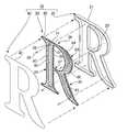
図1に、切り文字タイプの照明装置を示している。この照明装置10は、全体の形状が文字、本例では「R」の形状に沿って切られた周端11を含み、切り文字照明(切り文字看板)とも称される照明装置であり、商業施設などの建屋の壁面1に取り付けられるものである。この装置10は、正面、側面または背面が発光し、光る看板として機能する。 FIG. 1 shows a cut character type lighting device. This
図2に、照明装置10の概略構成を、展開図を用いて示している。照明装置10は、文字Rの形状(切り文字形状)に加工された金属製または樹脂製のシェル(ボックス、コンテナ)20と、切り文字形状に切断または成形された導光板30と、導光板30の周端31に取り付けられたLEDラインテープ50と、樹脂製の表面拡散板40とを含む。シェル20は、切り文字形状(本例ではR字形状)の外周を形成する側壁(周端)21と、照明装置10の後面を構成する底壁22とを含む。導光板30はシェル20の中に収納され、表面拡散板40はシェル20の前方を覆う蓋として機能する。導光板30には複数の取り付け穴39が設けられており、複数のネジあるいはボルト29によりシェル20に固定される。表面拡散板40は、端部41がテーパになっており、シェル20の前方に嵌め込んだ後に、接着材またはシール材によりシェル20に固定される。 In FIG. 2, the schematic structure of the
表面拡散板40は、透光製のアクリル、ポリカーボネートなどの樹脂製の板をレーザーカットなどの加工方法により文字形状に切り出したものであり、全体が乳白色でシェル20の内部が直に透視できないようになっている。表面拡散板40は裏面が粗面化されていてもよく、乳白色以外の色に着色されていてもよい。表面拡散板40にテーパをつけてシェル20に嵌め込む代わりに、シェル20の前方にフレームを設けて裏側から表面拡散板40を取り付けるようにしてもよい。 The
導光板30は、透明なアクリル、ポリカーボネートなどの樹脂製の板をレーザーカットなどの加工方法により文字形状に切り出したものである。導光板30は、断面がU字型またはV字型に刻まれたライン状の溝60を含む。これらの溝60は、導光板30のいくつかの部分の輪郭に相似する多重の線画を描くように刻まれており、この導光板30は、幅広の部分33、34および35にそれぞれ形成された3つの溝群63、64および65を含む。導光板30の狭い部分36および37には溝60は形成されていない。 The
図3に、導光板30を拡大して示している。導光板30は文字「R」の形状に切り出されており、その周囲(周端、周面)31には全周にわたりLEDテープ50が取り付けられている。LEDテープ(LEDラインテープ、LEDフレキシブルテープ)50は、粘着性のテープ52に所定の間隔、たとえば、2〜5cm程度の間隔をあけてLEDチップ51が取り付けられたものである。したがって、LEDテープ50に通電することにより、導光板30に、全周方向から照明用の光を入射できる。 FIG. 3 shows the
R字型の導光板30は、左端の縦に長い幅広の部分(第1の部分)33と、右側に凸に湾曲した幅広の部分(第2の部分)34と、右下に延びた幅広の部分(第3の部分)35と、第1の部分33と第2の部分34とを接続する狭い部分(第4の部分)36と、第1の部分33と第3の部分35とを接続する狭い部分(第5の部分)37とを含む。幅広の第1の部分33、第2の部分34および第3の部分35には、それぞれ複数の溝が多重(同心状)に形成された溝群63、64および65が形成されており、幅が狭い第4の部分36および第5の部分37には溝が形成されていない。 The R-shaped
左側の幅広の全体としてI字形状の第1の部分33に形成された溝群63は、第1の部分33の輪郭にほぼ相似するI字の周囲を線で描くように形成された第1の溝63a、第2の溝63bおよび第3の溝63cを含む。第1〜第3の溝63a〜63cは、多重になるように形成されており、第1の部分33の輪郭にほぼ相似し、最も小さいI字の輪郭を描くように形成された第3の溝63cの外側に、第3の溝63cよりも大きく、第1の部分33の輪郭にほぼ相似する形状を描くように形成された第2の溝63bが設けられ、その外側に、第2の溝63bよりもさらに大きく、第1の部分33の輪郭にほぼ相似する形状を描くように形成された第1の溝63aが設けられている。 A
右側に凸で全体が逆C字状の幅広の第2の部分34に形成された溝群64は、第2の部分34にほぼ相似する逆C字の輪郭を線で描くように形成された第1の溝64a、第2の溝64b、第3の溝64cおよび第4の溝64dを含む。第1〜第4の溝64a〜64dは、多重になるように形成されており、第2の部分34の輪郭にほぼ相似し、最も大きい逆C字の輪郭(周囲)を描くように形成された第1の溝64aの内側に、第1の溝64aよりも小さく、第2の部分34の輪郭にほぼ相似する形状を描くように形成された第2の溝64bが設けられ、その内側に、第2の溝64bよりもさらに小さく、第2の部分34の輪郭にほぼ相似する形状を描くように形成された第3の溝64cが設けられ、さらにその内側に、第3の溝64cよりもさらに小さく、第2の部分34にほぼ相似する形状を描くように形成された第4の溝64dが設けられている。 The
右下に筋交い(ブレース)状に延びた幅広の第3の部分35に形成された溝群65は、第3の部分35にほぼ相似する、ブレース状の形状の輪郭を線で描くように形成された第1の溝65a、第2の溝65bおよび第3の溝65cを含む。第1〜第3の溝65a〜65dは、多重になるように形成されており、第3の部分35の輪郭にほぼ相似し、最も大きい線画を描くように形成された第1の溝65aの内側に、第1の溝65aよりも小さく、第3の部分35の輪郭にほぼ相似する線画を描くように形成された第2の溝65bが設けられ、その内側に、第2の溝65bよりもさらに小さく、第3の部分35の輪郭にほぼ相似する線画を描くように形成された第3の溝65cが設けられている。 The
この導光板30においては、溝群64および65の最も外側の第1の溝64aおよび65aは繋がっており、全体として、文字Rの右側の部分の輪郭に相似する形状を描くように、溝64aおよび65aが形成されている。 In the
図4に、照明装置10を、導光板30の第1の部分33を含む断面で切った様子を示している。導光板30は、シェル20の後方8bの底板22に面した表面(この場合は裏面)38bから削られた(掘られた)溝60を含む。第1の部分33の溝群63は、外側から第1の溝63a、第2の溝63bおよび第3の溝63cを含む。第1の部分33の幅は約50mmであり、第1〜第3の溝63a〜63cが5〜10mm前後の間隔を開けて配置されている。それぞれの溝60(63a〜63c)の幅は1.5〜3mm程度、深さが0.5〜2mm程度である。溝60の幅および深さは、溝60を設ける導光板30の幅広の部分の幅、導光板30の厚さに依存し、上記の寸法に限定されない。しかしながら、溝60の幅は1〜40mm程度であることが望ましく、1.5〜20mm程度であることがさらに好ましい。溝60の深さは、0.5〜10mm程度であることが好ましく、隣接する溝60同士の間で深さが同一であってもよく、異なってもよい。導光板30を面でより均一に発光させるためには多重に形成された溝の内、輪郭に近い溝60が輪郭から遠い溝60に対して浅い方が望ましい。すなわち、導光板30の、輪郭にほぼ相似する複数の溝が多重に設けられた領域においては、中央に近い溝60の方が、周囲(輪郭)に近い溝60よりも深いことが好ましい。溝60の断面はU字型またはV字型であることが望ましい。 FIG. 4 shows a state in which the
この導光板30においては、端面(周端)31に取り付けられたLED51からの光が端面31から導光板30の内部に入り、入射した角度により、一部の光が導光板30の表面38aの前方8aに出力され、一部の光が導光板30の表面38aおよび裏面38bで全反射して導光板30の内部に定在する。導光板30の内部に定在した光は、裏面38bに設けられた溝60(63a〜63c)で散乱して角度が変わり、これらの溝60(63a〜63c)を発光源として導光板30の表面38aから前方8aに出力される。そして、導光板30から前方8aに出力された光は、照明装置10の表面拡散板40を全体的に照明し、表面拡散板40を均一に光らせる。したがって、切り文字状の表面拡散板40が均一に、明るく光る照明装置10を提供できる。 In this
この導光板30においては、幅広の部分33、34および35に、その幅広の部分の輪郭にほぼ相似した複数の溝60(63a〜63c、64a〜64d、65a〜65c)が多重に形成され、それらの溝60が発光部分となる。したがって、導光板30の幅広の部分33、34および35では、内部に、幅広の部分33、34および35の輪郭に相似する多重の発光部分が形成され、幅広の部分33、34および35が、より均等に発光する。さらに、導光板30の幅が狭い部分36および37には溝60が形成されないので、狭い部分36および37は内部に発光部分を持たない。このため、導光板30の幅が狭い部分36および37は、導光板30の表面38aから漏れ出る光で発光する。したがって、導光板30は、全体として均一な面発光に近い光源として利用でき、表面拡散板40を、各部分の幅にほぼ対応した光量で照明でき、表面拡散板40を均一に光らせることができる。 In the
図5(a)に導光板30にレーザー光71により溝60を形成する様子を模式的に示している。レーザー加工装置70は、レーザー光源75と、レーザー光71の向きを制御するミラー76を備えている。この例では、導光板30に溝60を形成(掘る)際に、レーザー光71を、導光板30におけるレーザー光71の軌跡79が円形または楕円になるように照射する。溝60の幅および深さは、レーザー光71の強度とともに、レーザー光71で描く円形または楕円の軌跡79の径や、回転周期、移動速度を変えることにより制御できる。また、このように形成された溝60の内面68には、レーザー光71の軌跡79による円弧状の凹凸69が形成される。 FIG. 5A schematically shows a state in which the
その結果、図5(b)に示すように、導光板30に彫られたすべての溝60の内面(表面)68には、円弧状の凹凸が密に形成される。このため、溝60の内面68は粗面化されており、導光板30の内部を伝達する光は、溝60の内面68で屈折されるとともに散乱され、効率よく光を導光板30の表面38aまたは裏面38bに向けて放出できる。特に、溝60に設けられた円弧状の凹凸69は、凸状または凹状が溝60の長手方向にほぼ直交する方向に延び、溝60の長手方向に沿って凸凹になる。したがって、溝60に入り込んだ光は、長手方向に直交する凹部や凸部に導かれ、溝60の内部に入りやすく、溝60の全体で光が散乱され、溝60の全体が光源となりやすい。このため、より面発光に近い導光板30を提供できる。 As a result, as shown in FIG. 5B, arc-shaped irregularities are densely formed on the inner surfaces (surfaces) 68 of all the
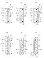
図6(a)〜(f)に、導光板30を用いた照明装置のいくつかの例を示している。図6(a)は、上述した照明装置10であり、導光板30から前方8aに出力された光5により表面拡散板40を照明するものである。図6(b)の照明装置10bは、同様に、導光板30から前方8aに出力された光5により表面拡散板40を照明するものであるが、シャーシ20の前方8aに表面拡散板40を支持するフレーム25を設けている。 FIG. 6A to FIG. 6F show some examples of lighting devices using the
図6(c)の照明装置10cは、後方8bに裏面拡散板45を設け、導光板30から前方8aおよび後方8bに出力された光5により表面拡散板40および裏面拡散板45を照明するものである。導光板30は、前方8aのみならず後方8bにも均等に光5を放出できるので、正面および裏面発光タイプであって、より均一な照明光5を放出できる照明装置10cを提供できる。 The
図6(d)の照明装置10dは、側方8cに側面拡散板46を設け、導光板30から前方8aに出力された光5により表面拡散板40および側面拡散板46を照明するものである。導光板30は面発光装置として高い機能を備えているので、側面に設けられた拡散板46も十分な強度で照明でき、正面および側面発光タイプオン照明装置10dを供給できる。図6(e)の照明装置10eは、裏面拡散板45を設け、他の面をシャーシ20で覆い、導光板30から後方8bに出力された光5により裏面拡散板45を照明する、裏面発光タイプの照明装置である。図6(f)の照明装置10fは、側面拡散板46を設け、他の面をシャーシ20で覆い、導光板30から後方8bに出力された光5により側面拡散板46を照明する、側面発光タイプの照明装置である。 The illuminating
導光板30を用いた照明装置は上記に限定されないが、本例の導光板30は、高輝度な均一発光が可能であり、面発光装置として優れた性能を備えている。このため、多種多様な方向に光を放出でき、正面に限らず、裏面および/または側面から高輝度の光を出力する照明装置を提供できる。 The lighting device using the
なお、上記では、切り文字の例として「R」に周囲が成形された照明装置を例に説明しているが、照明装置として提供できる切り文字は「R」に限らず、他のアルファベット文字であってもよく、ひらがな、カタカナ、漢字であってもよい。さらに、照明装置として提供できる切り文字は、ハングル文字、アラビア文字などであってもよい。また、照明装置として提供できる形状は切り文字に限定されず、企業のロゴマークやその他の図形、絵柄を模ったものであってもよい。幅広の部分と狭い部分とを含む、複雑な形状の照明装置であっても、上記の導光板30を用いることにより、より均一に、高輝度で発光する照明装置を提供できる。 In the above description, an example of a cut character has been described with an illumination device having a periphery formed as “R” as an example. However, the cut character that can be provided as the illumination device is not limited to “R”, and other alphabet characters. It may be hiragana, katakana, or kanji. Further, the cut character that can be provided as the lighting device may be a Hangul character, an Arabic character, or the like. In addition, the shape that can be provided as the lighting device is not limited to a cut character, and may be a shape imitating a company logo mark, other figures, or a pattern. Even if the illumination device has a complicated shape including a wide portion and a narrow portion, the illumination device that emits light more uniformly and with high luminance can be provided by using the
10 照明装置、 20 シャーシ、 30 導光板、 40 表面拡散板10 lighting device, 20 chassis, 30 light guide plate, 40 surface diffusion plate
Claims (6)
Translated fromJapanese前記第1の形状に略相似する形状に切り出された導光板と、
前記第1の形状に略相似する形状に切り出された前記導光板の周端の全周にわたり設けられた発光素子群とを有し、
前記導光板は、前記第1の形状に含まれる複数の幅広く切り出された部分を含み、前記複数の幅広く切り出された部分は、断面がU字型またはV字型のライン状の溝であって前記複数の幅広く切り出された部分のそれぞれの部分の輪郭と略相似する線画を多重に描くように形成された溝を含み、
前記導光板は、さらに、前記第1の形状に含まれ、前記複数の幅広く切り出された部分の少なくともいずれかを接続する形状に幅狭く切り出された部分であって、前記溝が形成されていない幅狭く切り出された部分を含む、照明装置。A lighting device including a peripheral edge along a first shape including a character or a pattern,
A light guide plate cut into a shape substantially similar to the first shape;
A light emitting element group provided over the entire circumference of the peripheral edge of the light guide plate cut into a shape substantially similar to the first shape,
The light guide plateincludes a plurality of broad cut-out portion included in said firstshape, said plurality of broad cut-out portion in cross section a line-shaped groove of the U-shaped or V-shapedlook containing a plurality of broad cut-out respective portions of the contour and a groove formed to draw a line drawing that generally similar to the multiplexingpart,
The light guide plate is further included in the first shape, and is a portion that is cut out narrowly into a shape that connects at least one of the plurality of broadly cut out portions, and the groove is not formed. A lighting deviceincluding a part cut out narrowly.
前記溝は、前記導光板の表面を、円弧で前記線画を描くように重畳走査されたレーザー光により加工されたものであり、前記溝の表面に円弧上の凹凸が形成されている、照明装置。In claim 1,
The groove is formed by processing the surface of the light guide plate with a laser beam that is superimposed and scanned so as to draw the line image in an arc, and the groove has an uneven surface on the arc. .
前記第1の形状に略相似する形状の表面拡散板をさらに有する、照明装置。In claim 1 or 2,
A lighting device further comprising a surface diffusion plate having a shape substantially similar to the first shape.
前記第1の形状は、看板用の切り文字である、照明装置。In any of claims 1 to 3,
Said 1st shape is an illuminating device which is a character for a signboard.
前記溝の幅は1〜40mmである、照明装置。In any of claims 1 to 4,
The width | variety of the said groove | channel is an illuminating device which is 1-40 mm.
前記第1の形状に含まれる複数の幅広く切り出された部分を含み、前記複数の幅広く切り出された部分は、断面がU字型またはV字型のライン状の溝であって前記複数の幅広く切り出された部分のそれぞれの部分の輪郭と略相似する線画を多重に描くように形成された溝を含み、
当該導光板は、さらに、前記第1の形状に含まれ、前記複数の幅広く切り出された部分の少なくともいずれかを接続する形状に幅狭く切り出された部分であって、前記溝が形成されていない幅狭く切り出された部分を含む、導光板。A light guide plate in which a light emitting element group is provided over the entire circumference of a peripheral end cut out in a first shape including a character or a pattern,
A plurality of broadly cut portions included in the first shape, wherein the plurality of widely cut portions are U-shaped or V-shaped line-shaped grooves, and theplurality of widely cutportions;Including a groove formed so as to draw a line drawing substantially similar to the outlineof each part of the formed part,
The light guide plate is further included in the first shape, and is a portion that is cut out narrowly into a shape that connects at least one of the plurality of broadly cut out portions, and the groove is not formed. width narrow cut-out portions including the light guide plate.
Priority Applications (1)
| Application Number | Priority Date | Filing Date | Title |
|---|---|---|---|
| JP2012048074AJP5103552B1 (en) | 2012-03-05 | 2012-03-05 | Lighting device |
Applications Claiming Priority (1)
| Application Number | Priority Date | Filing Date | Title |
|---|---|---|---|
| JP2012048074AJP5103552B1 (en) | 2012-03-05 | 2012-03-05 | Lighting device |
Publications (2)
| Publication Number | Publication Date |
|---|---|
| JP5103552B1true JP5103552B1 (en) | 2012-12-19 |
| JP2013182252A JP2013182252A (en) | 2013-09-12 |
Family
ID=47528512
Family Applications (1)
| Application Number | Title | Priority Date | Filing Date |
|---|---|---|---|
| JP2012048074AActiveJP5103552B1 (en) | 2012-03-05 | 2012-03-05 | Lighting device |
Country Status (1)
| Country | Link |
|---|---|
| JP (1) | JP5103552B1 (en) |
Families Citing this family (1)
| Publication number | Priority date | Publication date | Assignee | Title |
|---|---|---|---|---|
| JP2016061931A (en)* | 2014-09-18 | 2016-04-25 | Free Shine株式会社 | Cut letter led signboard |
Citations (10)
| Publication number | Priority date | Publication date | Assignee | Title |
|---|---|---|---|---|
| JPS4927401U (en)* | 1972-06-08 | 1974-03-08 | ||
| JP2003045214A (en)* | 2001-07-27 | 2003-02-14 | Airesu Denshi Kogyo Kk | Light-emitting device |
| JP2004302397A (en)* | 2003-03-31 | 2004-10-28 | Ono Gijutsu Kenkyusho:Kk | Light guide display plate |
| JP2006049385A (en)* | 2004-07-30 | 2006-02-16 | Toyoda Gosei Co Ltd | Light-emitting device |
| JP2007234617A (en)* | 2007-06-01 | 2007-09-13 | Nippon Leiz Co Ltd | Light guide plate and surface illumination device |
| JP2008027886A (en)* | 2006-01-27 | 2008-02-07 | Opt Design:Kk | Surface illumination light source device and surface illumination device using the same |
| JP2008186649A (en)* | 2007-01-29 | 2008-08-14 | Kurabe Ind Co Ltd | Illumination device |
| JP2008256920A (en)* | 2007-04-04 | 2008-10-23 | Md Form:Kk | Illumination cut character for signboard |
| JP2010147012A (en)* | 2008-12-22 | 2010-07-01 | Panasonic Electric Works Co Ltd | Planar light source, and display lighting fixture |
| JP2011198754A (en)* | 2010-03-18 | 2011-10-06 | Young Lighting Technology Inc | Light guide plate, and light source apparatus |
- 2012
- 2012-03-05JPJP2012048074Apatent/JP5103552B1/enactiveActive
Patent Citations (10)
| Publication number | Priority date | Publication date | Assignee | Title |
|---|---|---|---|---|
| JPS4927401U (en)* | 1972-06-08 | 1974-03-08 | ||
| JP2003045214A (en)* | 2001-07-27 | 2003-02-14 | Airesu Denshi Kogyo Kk | Light-emitting device |
| JP2004302397A (en)* | 2003-03-31 | 2004-10-28 | Ono Gijutsu Kenkyusho:Kk | Light guide display plate |
| JP2006049385A (en)* | 2004-07-30 | 2006-02-16 | Toyoda Gosei Co Ltd | Light-emitting device |
| JP2008027886A (en)* | 2006-01-27 | 2008-02-07 | Opt Design:Kk | Surface illumination light source device and surface illumination device using the same |
| JP2008186649A (en)* | 2007-01-29 | 2008-08-14 | Kurabe Ind Co Ltd | Illumination device |
| JP2008256920A (en)* | 2007-04-04 | 2008-10-23 | Md Form:Kk | Illumination cut character for signboard |
| JP2007234617A (en)* | 2007-06-01 | 2007-09-13 | Nippon Leiz Co Ltd | Light guide plate and surface illumination device |
| JP2010147012A (en)* | 2008-12-22 | 2010-07-01 | Panasonic Electric Works Co Ltd | Planar light source, and display lighting fixture |
| JP2011198754A (en)* | 2010-03-18 | 2011-10-06 | Young Lighting Technology Inc | Light guide plate, and light source apparatus |
Also Published As
| Publication number | Publication date |
|---|---|
| JP2013182252A (en) | 2013-09-12 |
Similar Documents
| Publication | Publication Date | Title |
|---|---|---|
| US7681347B1 (en) | Edge lit sign with illuminated image | |
| JP4825165B2 (en) | Display device | |
| CN209045098U (en) | A kind of invisible stereo luminous mark | |
| KR20150033648A (en) | Lighting device on a laundry appliance | |
| KR101521733B1 (en) | Display unit including light guide plate, traffic sign including the display unit, and method of manufacturing the traffic sign | |
| JP2008275921A (en) | Display device | |
| JP2008299116A (en) | machine | |
| JP4650165B2 (en) | Decoration device and game machine | |
| JP5103552B1 (en) | Lighting device | |
| JP2007294372A (en) | Surface light source device and display device | |
| JP2004361628A (en) | Illumination signboard | |
| TWM312683U (en) | Improvement structure of light source of backlight module of liquid crystal display | |
| JP2006181372A (en) | Game machine with illuminating device | |
| JP6536439B2 (en) | Light guide member of decoration device | |
| JP3148425U (en) | vending machine | |
| KR20180124128A (en) | An illumination assembly providing back illumination | |
| JP5828687B2 (en) | Display light guide plate and display device including display light guide plate | |
| TWI387707B (en) | Light guide film and light source module | |
| JP5124698B1 (en) | Light guide plate and wall guide plate provided with light guide plate | |
| JP5022927B2 (en) | Signage lighting system | |
| JP5086158B2 (en) | LED lighting device | |
| JP2006125144A (en) | Inside illumination type sign device | |
| TWI490572B (en) | Light guide plates,displays using these light guide plates, road signs including these displays, methodsfor manufacturing light guide plates and methods for manufacturing road signs | |
| JP2005055816A (en) | Display apparatus | |
| JP5950145B2 (en) | Internally illuminated display board |
Legal Events
| Date | Code | Title | Description |
|---|---|---|---|
| TRDD | Decision of grant or rejection written | ||
| A01 | Written decision to grant a patent or to grant a registration (utility model) | Free format text:JAPANESE INTERMEDIATE CODE: A01 Effective date:20120914 | |
| A01 | Written decision to grant a patent or to grant a registration (utility model) | Free format text:JAPANESE INTERMEDIATE CODE: A01 | |
| A61 | First payment of annual fees (during grant procedure) | Free format text:JAPANESE INTERMEDIATE CODE: A61 Effective date:20121001 | |
| FPAY | Renewal fee payment (event date is renewal date of database) | Free format text:PAYMENT UNTIL: 20151005 Year of fee payment:3 | |
| R150 | Certificate of patent or registration of utility model | Ref document number:5103552 Country of ref document:JP Free format text:JAPANESE INTERMEDIATE CODE: R150 Free format text:JAPANESE INTERMEDIATE CODE: R150 | |
| R250 | Receipt of annual fees | Free format text:JAPANESE INTERMEDIATE CODE: R250 | |
| R250 | Receipt of annual fees | Free format text:JAPANESE INTERMEDIATE CODE: R250 | |
| R250 | Receipt of annual fees | Free format text:JAPANESE INTERMEDIATE CODE: R250 | |
| R250 | Receipt of annual fees | Free format text:JAPANESE INTERMEDIATE CODE: R250 |