JP5101519B2 - Equipment interface for robotic surgery system - Google Patents
Equipment interface for robotic surgery systemDownload PDFInfo
- Publication number
- JP5101519B2 JP5101519B2JP2008547535AJP2008547535AJP5101519B2JP 5101519 B2JP5101519 B2JP 5101519B2JP 2008547535 AJP2008547535 AJP 2008547535AJP 2008547535 AJP2008547535 AJP 2008547535AJP 5101519 B2JP5101519 B2JP 5101519B2
- Authority
- JP
- Japan
- Prior art keywords
- manipulator
- instrument
- interface
- sterile adapter
- surgical
- Prior art date
- Legal status (The legal status is an assumption and is not a legal conclusion. Google has not performed a legal analysis and makes no representation as to the accuracy of the status listed.)
- Active
Links
- 238000002432robotic surgeryMethods0.000title1
- 230000008878couplingEffects0.000claimsabstractdescription13
- 238000010168coupling processMethods0.000claimsabstractdescription13
- 238000005859coupling reactionMethods0.000claimsabstractdescription13
- 230000005355Hall effectEffects0.000claimsdescription14
- 239000000523sampleSubstances0.000claimsdescription6
- 238000004140cleaningMethods0.000claimsdescription3
- 230000001681protective effectEffects0.000claimsdescription3
- 238000003780insertionMethods0.000description28
- 230000037431insertionEffects0.000description28
- 238000001356surgical procedureMethods0.000description21
- 238000009434installationMethods0.000description19
- 230000033001locomotionEffects0.000description17
- 238000000034methodMethods0.000description12
- 230000007246mechanismEffects0.000description8
- 238000004891communicationMethods0.000description7
- 238000013461designMethods0.000description6
- 230000008901benefitEffects0.000description5
- 230000036512infertilityEffects0.000description5
- 230000000712assemblyEffects0.000description4
- 238000000429assemblyMethods0.000description4
- 230000004888barrier functionEffects0.000description4
- 230000005540biological transmissionEffects0.000description4
- 238000012545processingMethods0.000description4
- 230000008859changeEffects0.000description3
- 230000006870functionEffects0.000description3
- 238000003384imaging methodMethods0.000description3
- 210000000707wristAnatomy0.000description3
- 230000000694effectsEffects0.000description2
- 238000007667floatingMethods0.000description2
- 238000002324minimally invasive surgeryMethods0.000description2
- 230000036316preloadEffects0.000description2
- 238000011084recoveryMethods0.000description2
- 230000004044responseEffects0.000description2
- 208000002847Surgical WoundDiseases0.000description1
- 230000002411adverseEffects0.000description1
- 238000013459approachMethods0.000description1
- 210000004204blood vesselAnatomy0.000description1
- 230000001112coagulating effectEffects0.000description1
- 230000015271coagulationEffects0.000description1
- 238000005345coagulationMethods0.000description1
- 238000010878colorectal surgeryMethods0.000description1
- 238000012790confirmationMethods0.000description1
- 230000000881depressing effectEffects0.000description1
- 238000001514detection methodMethods0.000description1
- 238000002405diagnostic procedureMethods0.000description1
- 238000010586diagramMethods0.000description1
- 238000005516engineering processMethods0.000description1
- 210000004247handAnatomy0.000description1
- 230000006872improvementEffects0.000description1
- 230000013011matingEffects0.000description1
- 238000012978minimally invasive surgical procedureMethods0.000description1
- 238000012986modificationMethods0.000description1
- 230000004048modificationEffects0.000description1
- 238000011022operating instructionMethods0.000description1
- 238000004806packaging method and processMethods0.000description1
- 230000002980postoperative effectEffects0.000description1
- 230000008569processEffects0.000description1
- 239000007787solidSubstances0.000description1
- 230000001954sterilising effectEffects0.000description1
- 238000004659sterilization and disinfectionMethods0.000description1
- 239000000758substrateSubstances0.000description1
- 238000012549trainingMethods0.000description1
Images


Classifications
- B—PERFORMING OPERATIONS; TRANSPORTING
- B25—HAND TOOLS; PORTABLE POWER-DRIVEN TOOLS; MANIPULATORS
- B25J—MANIPULATORS; CHAMBERS PROVIDED WITH MANIPULATION DEVICES
- B25J9/00—Programme-controlled manipulators
- B25J9/10—Programme-controlled manipulators characterised by positioning means for manipulator elements
- B25J9/104—Programme-controlled manipulators characterised by positioning means for manipulator elements with cables, chains or ribbons
- B25J9/1045—Programme-controlled manipulators characterised by positioning means for manipulator elements with cables, chains or ribbons comprising tensioning means
- A—HUMAN NECESSITIES
- A61—MEDICAL OR VETERINARY SCIENCE; HYGIENE
- A61B—DIAGNOSIS; SURGERY; IDENTIFICATION
- A61B17/00—Surgical instruments, devices or methods
- A—HUMAN NECESSITIES
- A61—MEDICAL OR VETERINARY SCIENCE; HYGIENE
- A61B—DIAGNOSIS; SURGERY; IDENTIFICATION
- A61B1/00—Instruments for performing medical examinations of the interior of cavities or tubes of the body by visual or photographical inspection, e.g. endoscopes; Illuminating arrangements therefor
- A61B1/00147—Holding or positioning arrangements
- A61B1/00149—Holding or positioning arrangements using articulated arms
- A—HUMAN NECESSITIES
- A61—MEDICAL OR VETERINARY SCIENCE; HYGIENE
- A61B—DIAGNOSIS; SURGERY; IDENTIFICATION
- A61B34/00—Computer-aided surgery; Manipulators or robots specially adapted for use in surgery
- A61B34/30—Surgical robots
- A—HUMAN NECESSITIES
- A61—MEDICAL OR VETERINARY SCIENCE; HYGIENE
- A61B—DIAGNOSIS; SURGERY; IDENTIFICATION
- A61B34/00—Computer-aided surgery; Manipulators or robots specially adapted for use in surgery
- A61B34/30—Surgical robots
- A61B34/37—Leader-follower robots
- A—HUMAN NECESSITIES
- A61—MEDICAL OR VETERINARY SCIENCE; HYGIENE
- A61B—DIAGNOSIS; SURGERY; IDENTIFICATION
- A61B34/00—Computer-aided surgery; Manipulators or robots specially adapted for use in surgery
- A61B34/70—Manipulators specially adapted for use in surgery
- A61B34/71—Manipulators operated by drive cable mechanisms
- B—PERFORMING OPERATIONS; TRANSPORTING
- B25—HAND TOOLS; PORTABLE POWER-DRIVEN TOOLS; MANIPULATORS
- B25J—MANIPULATORS; CHAMBERS PROVIDED WITH MANIPULATION DEVICES
- B25J15/00—Gripping heads and other end effectors
- B25J15/04—Gripping heads and other end effectors with provision for the remote detachment or exchange of the head or parts thereof
- A—HUMAN NECESSITIES
- A61—MEDICAL OR VETERINARY SCIENCE; HYGIENE
- A61B—DIAGNOSIS; SURGERY; IDENTIFICATION
- A61B17/00—Surgical instruments, devices or methods
- A61B2017/00017—Electrical control of surgical instruments
- A61B2017/00212—Electrical control of surgical instruments using remote controls
- A—HUMAN NECESSITIES
- A61—MEDICAL OR VETERINARY SCIENCE; HYGIENE
- A61B—DIAGNOSIS; SURGERY; IDENTIFICATION
- A61B17/00—Surgical instruments, devices or methods
- A61B2017/00477—Coupling
- A—HUMAN NECESSITIES
- A61—MEDICAL OR VETERINARY SCIENCE; HYGIENE
- A61B—DIAGNOSIS; SURGERY; IDENTIFICATION
- A61B34/00—Computer-aided surgery; Manipulators or robots specially adapted for use in surgery
- A61B34/20—Surgical navigation systems; Devices for tracking or guiding surgical instruments, e.g. for frameless stereotaxis
- A61B2034/2046—Tracking techniques
- A61B2034/2059—Mechanical position encoders
- A—HUMAN NECESSITIES
- A61—MEDICAL OR VETERINARY SCIENCE; HYGIENE
- A61B—DIAGNOSIS; SURGERY; IDENTIFICATION
- A61B34/00—Computer-aided surgery; Manipulators or robots specially adapted for use in surgery
- A61B34/30—Surgical robots
- A61B2034/305—Details of wrist mechanisms at distal ends of robotic arms
- A—HUMAN NECESSITIES
- A61—MEDICAL OR VETERINARY SCIENCE; HYGIENE
- A61B—DIAGNOSIS; SURGERY; IDENTIFICATION
- A61B34/00—Computer-aided surgery; Manipulators or robots specially adapted for use in surgery
- A61B34/70—Manipulators specially adapted for use in surgery
- A61B34/71—Manipulators operated by drive cable mechanisms
- A61B2034/715—Cable tensioning mechanisms for removing slack
- A—HUMAN NECESSITIES
- A61—MEDICAL OR VETERINARY SCIENCE; HYGIENE
- A61B—DIAGNOSIS; SURGERY; IDENTIFICATION
- A61B46/00—Surgical drapes
- A61B46/20—Surgical drapes specially adapted for patients
- A61B46/23—Surgical drapes specially adapted for patients with means to retain or hold surgical implements
- A61B2046/234—Surgical drapes specially adapted for patients with means to retain or hold surgical implements with means for retaining a catheter
- A—HUMAN NECESSITIES
- A61—MEDICAL OR VETERINARY SCIENCE; HYGIENE
- A61B—DIAGNOSIS; SURGERY; IDENTIFICATION
- A61B90/00—Instruments, implements or accessories specially adapted for surgery or diagnosis and not covered by any of the groups A61B1/00 - A61B50/00, e.g. for luxation treatment or for protecting wound edges
- A61B90/08—Accessories or related features not otherwise provided for
- A61B2090/0804—Counting number of instruments used; Instrument detectors
- A61B2090/0805—Counting number of instruments used; Instrument detectors automatically, e.g. by means of magnetic, optical or photoelectric detectors
- A—HUMAN NECESSITIES
- A61—MEDICAL OR VETERINARY SCIENCE; HYGIENE
- A61B—DIAGNOSIS; SURGERY; IDENTIFICATION
- A61B90/00—Instruments, implements or accessories specially adapted for surgery or diagnosis and not covered by any of the groups A61B1/00 - A61B50/00, e.g. for luxation treatment or for protecting wound edges
- A61B90/36—Image-producing devices or illumination devices not otherwise provided for
- A61B90/37—Surgical systems with images on a monitor during operation
- A61B2090/371—Surgical systems with images on a monitor during operation with simultaneous use of two cameras
- A—HUMAN NECESSITIES
- A61—MEDICAL OR VETERINARY SCIENCE; HYGIENE
- A61B—DIAGNOSIS; SURGERY; IDENTIFICATION
- A61B90/00—Instruments, implements or accessories specially adapted for surgery or diagnosis and not covered by any of the groups A61B1/00 - A61B50/00, e.g. for luxation treatment or for protecting wound edges
- A61B90/36—Image-producing devices or illumination devices not otherwise provided for
- A61B90/361—Image-producing devices, e.g. surgical cameras
- G—PHYSICS
- G16—INFORMATION AND COMMUNICATION TECHNOLOGY [ICT] SPECIALLY ADAPTED FOR SPECIFIC APPLICATION FIELDS
- G16H—HEALTHCARE INFORMATICS, i.e. INFORMATION AND COMMUNICATION TECHNOLOGY [ICT] SPECIALLY ADAPTED FOR THE HANDLING OR PROCESSING OF MEDICAL OR HEALTHCARE DATA
- G16H20/00—ICT specially adapted for therapies or health-improving plans, e.g. for handling prescriptions, for steering therapy or for monitoring patient compliance
- G16H20/40—ICT specially adapted for therapies or health-improving plans, e.g. for handling prescriptions, for steering therapy or for monitoring patient compliance relating to mechanical, radiation or invasive therapies, e.g. surgery, laser therapy, dialysis or acupuncture
- G—PHYSICS
- G16—INFORMATION AND COMMUNICATION TECHNOLOGY [ICT] SPECIALLY ADAPTED FOR SPECIFIC APPLICATION FIELDS
- G16H—HEALTHCARE INFORMATICS, i.e. INFORMATION AND COMMUNICATION TECHNOLOGY [ICT] SPECIALLY ADAPTED FOR THE HANDLING OR PROCESSING OF MEDICAL OR HEALTHCARE DATA
- G16H40/00—ICT specially adapted for the management or administration of healthcare resources or facilities; ICT specially adapted for the management or operation of medical equipment or devices
- G16H40/60—ICT specially adapted for the management or administration of healthcare resources or facilities; ICT specially adapted for the management or operation of medical equipment or devices for the operation of medical equipment or devices
- G16H40/63—ICT specially adapted for the management or administration of healthcare resources or facilities; ICT specially adapted for the management or operation of medical equipment or devices for the operation of medical equipment or devices for local operation
- G—PHYSICS
- G16—INFORMATION AND COMMUNICATION TECHNOLOGY [ICT] SPECIALLY ADAPTED FOR SPECIFIC APPLICATION FIELDS
- G16H—HEALTHCARE INFORMATICS, i.e. INFORMATION AND COMMUNICATION TECHNOLOGY [ICT] SPECIALLY ADAPTED FOR THE HANDLING OR PROCESSING OF MEDICAL OR HEALTHCARE DATA
- G16H40/00—ICT specially adapted for the management or administration of healthcare resources or facilities; ICT specially adapted for the management or operation of medical equipment or devices
- G16H40/60—ICT specially adapted for the management or administration of healthcare resources or facilities; ICT specially adapted for the management or operation of medical equipment or devices for the operation of medical equipment or devices
- G16H40/67—ICT specially adapted for the management or administration of healthcare resources or facilities; ICT specially adapted for the management or operation of medical equipment or devices for the operation of medical equipment or devices for remote operation
- Y—GENERAL TAGGING OF NEW TECHNOLOGICAL DEVELOPMENTS; GENERAL TAGGING OF CROSS-SECTIONAL TECHNOLOGIES SPANNING OVER SEVERAL SECTIONS OF THE IPC; TECHNICAL SUBJECTS COVERED BY FORMER USPC CROSS-REFERENCE ART COLLECTIONS [XRACs] AND DIGESTS
- Y10—TECHNICAL SUBJECTS COVERED BY FORMER USPC
- Y10S—TECHNICAL SUBJECTS COVERED BY FORMER USPC CROSS-REFERENCE ART COLLECTIONS [XRACs] AND DIGESTS
- Y10S483/00—Tool changing
- Y10S483/901—Robot end effectors
- Y—GENERAL TAGGING OF NEW TECHNOLOGICAL DEVELOPMENTS; GENERAL TAGGING OF CROSS-SECTIONAL TECHNOLOGIES SPANNING OVER SEVERAL SECTIONS OF THE IPC; TECHNICAL SUBJECTS COVERED BY FORMER USPC CROSS-REFERENCE ART COLLECTIONS [XRACs] AND DIGESTS
- Y10—TECHNICAL SUBJECTS COVERED BY FORMER USPC
- Y10T—TECHNICAL SUBJECTS COVERED BY FORMER US CLASSIFICATION
- Y10T74/00—Machine element or mechanism
- Y10T74/20—Control lever and linkage systems
- Y10T74/20207—Multiple controlling elements for single controlled element
- Y10T74/20305—Robotic arm
Landscapes
- Health & Medical Sciences (AREA)
- Engineering & Computer Science (AREA)
- Life Sciences & Earth Sciences (AREA)
- Surgery (AREA)
- Robotics (AREA)
- Animal Behavior & Ethology (AREA)
- Public Health (AREA)
- Heart & Thoracic Surgery (AREA)
- Medical Informatics (AREA)
- Molecular Biology (AREA)
- Nuclear Medicine, Radiotherapy & Molecular Imaging (AREA)
- General Health & Medical Sciences (AREA)
- Biomedical Technology (AREA)
- Veterinary Medicine (AREA)
- Mechanical Engineering (AREA)
- Physics & Mathematics (AREA)
- Biophysics (AREA)
- Optics & Photonics (AREA)
- Pathology (AREA)
- Radiology & Medical Imaging (AREA)
- Manipulator (AREA)
Abstract
Description
Translated fromJapanese (関連出願の引用)
本願は、2005年12月20日出願の米国仮特許出願第60/752,755号の利益を主張し、該出願の(該出願において参考により援用された全ての参考文献を含む)全開示は、その全ての目的のために、本明細書において参考により援用される。(Citation of related application)
This application claims the benefit of US Provisional Patent Application No. 60 / 752,755, filed Dec. 20, 2005, including the entire disclosure of that application (including all references incorporated by reference). For all purposes thereof, incorporated herein by reference.
本願は、係属中の2005年12月20日に出願の米国特許出願第11/314,040号、名称「Sterile Surgical Adaptor」の一部継続出願であり、該出願は係属中の2004年8月19日に出願の米国特許出願第10/922,346号の一部継続出願であり、該出願は2001年10月30日出願の米国特許出願第10/004,399号の継続出願であり、該出願は1999年9月28日出願の米国特許出願第09/406,360号(現在では米国特許第6,346,072号)の継続出願であり、該出願は、1996年12月12日出願の米国仮特許出願第60/033,321号に対する優先権を主張した1997年11月21日出願の米国特許出願第08/975,617号(現在では米国特許第6,132,368号)の継続出願である。これらの出願の全開示は、その全ての目的のために、本明細書において参考により援用される。 This application is a continuation-in-part of US patent application Ser. No. 11 / 314,040, entitled “Sterile Surgical Adapter,” filed on Dec. 20, 2005, which is pending. A continuation-in-part of U.S. patent application Ser. No. 10 / 922,346 filed on 19th, which is a continuation of U.S. patent application Ser. No. 10 / 004,399, filed Oct. 30, 2001; The application is a continuation of US patent application Ser. No. 09 / 406,360 filed Sep. 28, 1999 (currently US Pat. No. 6,346,072), which was filed on Dec. 12, 1996. US patent application Ser. No. 08 / 975,617 filed Nov. 21, 1997, which claimed priority to US Provisional Patent Application No. 60 / 033,321 No. 6,132,368). The entire disclosures of these applications are incorporated herein by reference for all purposes.
本願は、2006年12月20日に出願の米国特許出願________、名称「Cable Tensioning In A Robotic Surgical System」(代理人整理番号第M−16315−1 US)、2006年12月20日に出願の米国特許出願________、名称「Telescoping Insertion Axis Of A Robotic Surgical System」(代理人整理番号第M−16315−2 US)、2006年11月3日に出願の米国特許出願第11/556,484号、名称「Indicator For Tool State and Communication In a Multi−Arm Robotic Telesurgery」、2006年12月20日に出願の米国特許出願________、名称「Wireless Communication In A Robotic Surgical System」(代理人整理番号第M−16315−5 US)、および2006年3月31日に出願の米国特許出願第11/395,418号、名称「Sterile Surgical Adaptor」に関する。これらの出願の(これらの出願において参考により援用された全ての参考文献を含む)全開示は、その全ての目的のために、本明細書において参考により援用される。 This application is a US patent application _______ filed on December 20, 2006, named “Cable Tensing In A Robotic Surgical System” (Attorney Docket No. M-16315-1 US), filed December 20, 2006. US patent application _______, name “Telescoping Insertion Axis Of A Robotic Surgical System” (Attorney Docket No. M-16315-2 US), US Patent Application No. 11 / 556,484, filed November 3, 2006, Name “Indicator For Tool State and Communication In a Multi-Arm Robotic Telesurgery”, December 2006 US patent application _______ filed on 0, name “Wireless Communication In A Robotic Surgical System” (Attorney Docket No. M-16315-5 US), and US Patent Application No. 11/11 filed March 31, 2006 No. 395,418, name “Sterile Surgical Adapter”. The entire disclosure of these applications (including all references incorporated by reference in these applications) are hereby incorporated by reference for all purposes.
本発明は、概して、医療用および/またはロボット装置、システム、および方法に関する。 The present invention generally relates to medical and / or robotic devices, systems, and methods.
低侵襲医療技術は、診断的または外科的処置の際に損傷を受ける外部組織の量を減少させ、それによって患者の回復時間、不快感、および有害な副作用を低減することを目的とする。低侵襲外科手術の効果の1つとして、例えば、術後の入院回復時間を短縮することができる。標準的外科手術における平均入院期間は、典型的に類似の低侵襲外科手術における平均入院期間よりも非常に長いため、低侵襲技術の使用を増加することによって、年間何百万ドルもの入院費用を節約することが可能となる。米国で毎年行われる外科手術の多くは低侵襲法によって行われ得るが、低侵襲外科手術用機器の制限およびそれらの習得に伴う付加的外科手術訓練から、現在の外科手術のほんの一部しかこのような有利な技術を使用していない。 Minimally invasive medical technology aims to reduce the amount of external tissue that is damaged during diagnostic or surgical procedures, thereby reducing patient recovery time, discomfort, and adverse side effects. As one of the effects of minimally invasive surgery, for example, postoperative hospitalization recovery time can be shortened. Because the average hospital stay in standard surgery is typically much longer than the average hospital stay in similar minimally invasive surgery, increasing the use of minimally invasive techniques can save millions of dollars in hospital costs per year. It is possible to save. Many of the surgical procedures performed annually in the United States can be performed by minimally invasive techniques, but this is only a small part of current surgery due to the limitations of minimally invasive surgical instruments and the additional surgical training that accompanies them. It does not use such an advantageous technique.
外科医の技術手腕を向上させ、従来の低侵襲技術におけるいくつかの制限を回避するための低侵襲ロボット外科手術用または遠隔外科手術システムが開発されている。遠隔外科手術では、外科医は、例えば、サーボ機構等の遠隔制御装置を使用して、手動で機器を直接保持したり、動かしたりすることなく、外科手術用機器の動きを操作する。遠隔外科手術システムでは、外科医は、外科手術用ワークステーションにおいて外科手術用部位の画像が提供され得る。ディスプレイ上で外科手術用部位の二次元または三次元画像を見ながら、外科医は、サーボ機構式機器の動作を制御する主制御装置(マスタ)を操作することによって、患者に外科的処置を行う。 Minimally invasive robotic surgical or telesurgical systems have been developed to improve the surgeon's technical skills and avoid some limitations in conventional minimally invasive techniques. In telesurgery, the surgeon uses a remote control device such as a servomechanism to manipulate the movement of the surgical instrument without manually holding or moving the instrument directly. In a telesurgical system, a surgeon may be provided with an image of a surgical site at a surgical workstation. While viewing a two-dimensional or three-dimensional image of the surgical site on the display, the surgeon performs a surgical procedure on the patient by manipulating a master controller (master) that controls the operation of the servo-mechanical instrument.
ロボット補助外科手術では、外科医は、典型的には、主制御装置を操作し、患者と離れた場所(例えば、手術室の向かい側、患者と離れた別の部屋または全く別の建物)から、外科手術用部位における外科手術用機器の動作を制御する。主制御装置は、通常、携帯用リストジンバル、ジョイスティック、外骨格グローブ等の1つ以上の手動入力装置を含み、患者側外科手術用マニピュレータ(「スレーブ」)に解放可能に結合された外科手術用機器に、動作可能に連結される。主制御装置は、外科手術用部位における機器の位置、配向、接合を制御する。スレーブは、電気機械アセンブリであって、外科手術用機器を支持および制御するために一体に接続された複数のアーム、関節部、連結部、サーボモータ等を含む。外科的処置では、外科手術用機器(内視鏡を含む)は、開口した外科手術用部位に直接導入されるか、より典型的には、トロカールスリーブを通して体腔に導入されてもよい。外科的処置に応じて、例えば、針の保持または駆動、縫合、血管の把持、細胞の切開、焼灼、凝固等、外科医が種々の機能を実行するため、細胞把持装置、持針器、電気外科手術用焼灼プローブ等の種々の外科手術用機器が利用可能である。 In robot-assisted surgery, the surgeon typically operates the main controller and operates from a location remote from the patient (eg, across the operating room, another room away from the patient, or a completely different building). Control the operation of the surgical instrument at the surgical site. The main controller typically includes one or more manual input devices, such as a portable wrist gimbal, joystick, exoskeleton glove, etc., and surgically coupled releasably to a patient-side surgical manipulator (“slave”) Operatively coupled to the device. The main controller controls the position, orientation, and bonding of the instrument at the surgical site. The slave is an electromechanical assembly and includes a plurality of arms, joints, linkages, servo motors, and the like that are connected together to support and control the surgical instrument. In a surgical procedure, surgical instruments (including endoscopes) may be introduced directly into an open surgical site or more typically through a trocar sleeve and into a body cavity. Depending on the surgical procedure, the cell grasping device, needle holder, electrosurgery, etc., for the surgeon to perform various functions such as holding or driving the needle, suturing, grasping the blood vessel, incision of the cell, cauterization, coagulation, etc. Various surgical instruments such as surgical cautery probes are available.
外科手術用マニピュレータアセンブリは、3つの主要構成要素に分けられるとされており、非殺菌駆動および制御構成要素、殺菌可能先端部または外科手術用道具/機器、中間コネクタ構成要素が含まれる。中間コネクタ構成要素は、外科手術用道具を駆動および制御構成要素と連結し、駆動構成要素から外科手術用道具へ動作を伝送するための機械的要素を含む。 The surgical manipulator assembly is said to be divided into three main components, including a non-sterile drive and control component, a sterilizable tip or surgical tool / equipment, and an intermediate connector component. The intermediate connector component includes a mechanical element for coupling the surgical tool with the drive and control component and transferring motion from the drive component to the surgical tool.
遠隔ロボット外科手術システムの課題は、典型的には、外科医が処置の際に多数の異なる外科手術用機器/道具を使用することになることである。空間的制約および費用によってマニピュレータアームの数は制限されてしまうため、これらの多くの外科手術用機器は、操作の間、何度もマニピュレータアームから着脱されることになる。 The challenge of remote robotic surgical systems is that surgeons typically use a number of different surgical instruments / tools during the procedure. Because the number of manipulator arms is limited by space constraints and costs, many of these surgical instruments will be removed from the manipulator arms many times during operation.
遠隔外科手術システム、装置、および方法は、非常に効果的かつ有利であると証明されているが、依然として、さらなる改良が望ましいであろう。概して、改良型機器インターフェースをマニピュレータアーム上に提供し、外科的処置の際の機器の交換時間および困難を最小化することが望ましいであろう。 While telesurgical systems, devices, and methods have proven very effective and advantageous, further improvements would still be desirable. In general, it would be desirable to provide an improved instrument interface on the manipulator arm to minimize instrument exchange time and difficulties during surgical procedures.
本発明の実施形態によると、ロボットマニピュレータの機器インターフェースが提供され、機器インターフェースは、機器を協働しうるように結合可能な無菌アダプタに、軸荷重およびトルクを提供するためのスプリング荷重入力部を含む。機器インターフェースは、スプリングプランジャおよびスプリング荷重解放レバーをさらに含んでもよい。 According to an embodiment of the present invention, an equipment interface of a robot manipulator is provided, the equipment interface having a spring load input for providing axial load and torque to an aseptic adapter that can be coupled to cooperate with the equipment. Including. The instrument interface may further include a spring plunger and a spring load release lever.
本発明の別の実施形態によると、ロボット外科手術用マニピュレータシステムが提供され、システムは、マニピュレータアームの遠位端に協働しうるように結合された基礎連結部と、縦方向軸に沿って基礎連結部に移動調整可能に連結された搬送連結部とを含むマニピュレータアセンブリを備え、搬送連結部は、上述のような機器インターフェースを含む。本システムは、機器インターフェースを介して搬送連結部に協働しうるように結合された機器と、機器および/または無菌アダプタを検出するためのマニピュレータアセンブリに協働しうるように結合されたプロセッサとをさらに含む。 According to another embodiment of the present invention, a robotic surgical manipulator system is provided, the system comprising a base connection operably coupled to the distal end of the manipulator arm, along the longitudinal axis. A manipulator assembly including a transport coupling unit coupled to the base coupling unit so as to be movable and adjustable, and the transport coupling unit includes an equipment interface as described above. The system includes a device operably coupled to the transport connection via the device interface, and a processor operably coupled to a manipulator assembly for detecting the device and / or sterility adapter. Further included.
有利には、本発明は、機器無菌アダプタ(Instrument Steri1e Adaptor;ISA)の単純かつ効率的な設置および/または係合を提供する一方で、ISAおよび無菌バリアのための費用効果的な使い捨て可能な設計を可能にする。本発明の他の利点も提供される。
Advantageously, the present invention provides a simple and efficient installation and / or engagement of an instrument sterilization adapter (ISA) while being a cost effective disposable for ISA and sterility barriers. Enable design. Other advantages of the invention are also provided.
本発明の範囲は請求項によって定義され、参照することによって本項に援用される。本発明の実施形態のより完全な理解は、当業者によって可能となり、1つ以上の実施形態の以下の詳細な説明を検討することによって、その付加的利点の実現が得られるであろう。最初に簡単に説明される添付の図面を参照されたい。 The scope of the present invention is defined by the claims, which are hereby incorporated by reference. A more complete understanding of the embodiments of the present invention will be possible by those skilled in the art, and upon reading the following detailed description of one or more embodiments, additional benefits thereof may be obtained. Reference is made to the accompanying drawings, which are briefly described first.
本発明の実施形態およびその利点は、後述の詳細な説明を参照することによって最も理解される。同一参照番号は、1つ以上の図において示される同様の要素を識別するために使用されることは理解されたい。また、図は、必ずしも正確な縮尺で描かれていないことも理解されたい。 Embodiments of the present invention and their advantages are best understood by referring to the detailed description that follows. It should be understood that the same reference numerals are used to identify similar elements shown in one or more figures. It should also be understood that the figures are not necessarily drawn to scale.
本発明は、概して、機器を挿入するための改良型ロボット挿入軸、システム、および方法を提供し、特に、より優れた剛性および強度、より広い動作範囲、外科手術野の向上した可視性を提供するための伸縮自在の挿入軸を含む。 The present invention generally provides improved robot insertion axes, systems, and methods for inserting instruments, particularly providing greater rigidity and strength, wider operating range, and improved visibility of the surgical field. Including a telescopic insertion shaft.
本発明は、遠隔ロボット外科手術システムの一部として特に有益であり、外科医が患者から離れた場所でサーボ機構を通して外科手術用機器を操作することを可能とする。ロボット外科手術システムの一実施例は、米国カリフォルニア州サニーベールにあるIntuitive Surgica1, Inc.から入手可能なda Vinci(登録商標) STM外科手術システムである。da Vinci(登録商標) STM外科手術システムの取扱説明書は、Intuitive Surgica1, Inc.から入手可能であり、あらゆる目的において参照することによって本願に援用される。The present invention is particularly useful as part of a remote robotic surgical system and allows a surgeon to manipulate surgical instruments through a servomechanism at a location remote from the patient. One example of a robotic surgical system is Intuitive Surgica 1, Inc., Sunnyvale, California, USA. A da Vinci (R)S TM surgical system available from. da Vinci (R) operating instructions of theS TM surgical system, Intuitive Surgica1, Inc. And are incorporated herein by reference for all purposes.
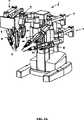
図1−3は、低侵襲ロボット外科手術を実施するためのロボット外科手術システム1の構成要素を示す。システム1は、米国特許第6,246,200号により詳細に説明され、参照することによって全開示が本願に援用されるシステムと類似するものである。システムオペレータO(概して、外科医)は、手術台T上に横たわる患者Pに低侵襲外科的処置を行う。システムオペレータOは、ディスプレイ12によって提示される画像を見ながら、外科医のコンソール3で1つ以上の入力装置または主制御装置2を操作する。外科医の入力コマンドに応じて、コンソール3のコンピュータプロセッサ4は、外科手術用機器または道具5の動きを指示し、関節部、連結部、およびそれぞれ伸縮自在の挿入軸を有するマニピュレータアームを含む患者側ロボットマニピュレータシステム6(本実施例ではカート式システム)を介して、機器のサーボ機構動作を生じさせる。一実施形態では、プロセッサ4が道具5の先端部の動きと相関することによって、先端部の動作は、システムオペレータOの手中の入力装置の動きに追随する。 1-3 show the components of a robotic surgical system 1 for performing a minimally invasive robotic surgical procedure. System 1 is described in more detail in US Pat. No. 6,246,200 and is similar to the system whose entire disclosure is incorporated herein by reference. The system operator O (generally a surgeon) performs a minimally invasive surgical procedure on a patient P lying on the operating table T. The system operator O operates one or more input devices or the
プロセッサ4は、典型的には、データ処理ハードウェアおよびソフトウェアを含み、ソフトウェアは、典型的には、機械可読コードを備える。機械可読コードは、ソフトウェアプログラミング命令を具現化し、本願に記載の方法の一部または全部を実装する。プロセッサ4は、図1の単純な概略図において単一のブロックとして示されているが、プロセッサは、少なくとも隣接する入力装置が実施する随意の処理の一部、隣接するマニピュレータが実施する一部等、いくつかのデータ処理回路を含んでもよい。多種多様な集中型または分散型データ処理アーキテクチャのいずれかを採用してもよい。同様に、プログラミングコードは、いくつかの別々のプログラムまたはサブルーチンとして実装してもよく、あるいは本願に記載のロボットシステムのいくつかの他の態様に統合してもよい。 The processor 4 typically includes data processing hardware and software, which typically comprises machine readable code. The machine readable code embodies software programming instructions and implements some or all of the methods described herein. The processor 4 is shown as a single block in the simple schematic of FIG. 1, but the processor is at least part of the optional processing performed by the adjacent input device, part of the adjacent manipulator, etc. Several data processing circuits may be included. Any of a wide variety of centralized or distributed data processing architectures may be employed. Similarly, the programming code may be implemented as several separate programs or subroutines, or may be integrated into some other aspect of the robotic system described herein.
一実施例では、マニピュレータシステム6は、少なくとも4つのロボットマニピュレータアセンブリを含む。3つの連結部7(本実施例ではカートの側面に搭載)は、概して、少なくとも外科的処置の一部の間、固定位置でマニピュレータ8の基礎部を支持する連結部7を有するマニピュレータ8を支持および位置調整する。マニピュレータ8は、細胞のロボット操作のための外科手術用道具5を動かす。1つの付加的連結部9(本実施例では、カートの中央に搭載)は、マニピュレータ10を支持および位置調整して、内視鏡/カメラプローブ11の動作を制御し、内部外科手術部位の画像(好ましくは、立体画像)を撮影する。患者側システムの位置調整連結部7、9の固定可能部分は、「設定アーム」として本願では称される場合がある。 In one embodiment, the
一実施例では、内部外科手術部位の画像は、外科医のコンソール3における立体画像ディスプレイ12によって、オペレータOに示される。内部外科手術部位は、アシスタントディスプレイ14によって、アシスタントAに同時に示される。 In one embodiment, an image of the internal surgical site is shown to the operator O by the
アシスタントAは、1つ以上の外科手術用マニピュレータから道具5または機器5’を代替外科手術用道具に交換する場合、非ロボット医療用機器および装置に関する操作を行う場合、手動でマニピュレータアセンブリを動かし、付随道具を異なる開口部を通して内部外科手術部位にアクセスさせる場合等、設定連結部アーム7、9を使用して、患者Pに対しマニピュレータアセンブリ8および10を事前に位置調整する際に補助を行う。 Assistant A manually moves the manipulator assembly when performing operations on non-robot medical devices and devices when replacing
概して、連結部7、9は、患者側システム6の設定の際に主に使用され、典型的には、少なくとも外科的処置の一部の間、固定された構成を維持したままである。マニピュレータ8、10は、それぞれ駆動連結部を備え、外科医のコンソール3による指示に基づいて能動的に連接される。1つ以上設定アームの関節部は、随意に駆動およびロボット制御されてもよいが、少なくとも設定アーム関節部の一部は、アシスタントAによって手動で位置調整されるように構成されてもよい。 In general, the
マニピュレータの一部は、本発明の実施形態による伸縮自在の挿入軸100を含むが、他の実施形態では、すべてのマニピュレータが伸縮自在の挿入軸100を含んでもよい。伸縮自在の挿入軸100によって、以下にさらに詳述するように(他の利点に加え)、3つの協働しうるように結合された結合部を介して、以前の設計に比べ優れた剛性および強度、より広い動作範囲、向上した動的性能、およびシステムユーザのための手術野に近位の可視性を有する、搭載された機器5の動きが可能となる。 A portion of the manipulator includes a
便宜上、細胞を操作するために使用される外科手術用道具を支持しているマニピュレータ8等のマニピュレータは、患者側マニピュレータ(Patient−Side Manipu1ator;PSM)と称され、内視鏡11等の撮像またはデータ取得装置を制御するマニピュレータ10は、内視鏡−カメラマニピュレータ(Endoscope−Camera Manipu1ator;ECM)と称される場合がある。マニピュレータは、外科手術に有益な他種多様な機器または道具、撮像装置等を随意に作動、操作、制御してもよい。 For convenience, a manipulator such as a
機器5および内視鏡11は、外科的処置のために設定する場合、外科的処置の異なる段階のためのマニピュレータシステム6を再構成する場合、機器を除去し代替機器5’と交換する場合等に、手動で位置調整されてもよい。アシスタントAによるマニピュレータアセンブリのそのような手動の再構成の際、マニピュレータアセンブリは、マスタ/スレーブ遠隔外科手術の際に使用されるモードとは異なるモードである、クラッチモードと称される場合がある手動再配置可能モードにしてもよい。マニピュレータアセンブリは、マニピュレータ8(例えば、図6A−6Cのクラッチボタン/スイッチ103)上のボタンまたはスイッチの押下、あるいはマニピュレータアセンブリの他の構成要素等の入力に応じて、細胞操作モードとクラッチモードを切り替え、アシスタントAにマニピュレータモードを変更させてもよい。 When the
図1および2A−2Bから分かるように、マニピュレータアセンブリ上に表示器20を配置してもよい。本実施形態では、表示器20は、マニピュレータと搭載された道具5との間のインターフェース近傍のマニピュレータ8上に配置される。代替実施形態では、表示器20は、代わりに、設定関節部7、9上、道具5上、マニピュレータ8、10上のいずれかの場所等に配置してもよい。表示器の実施例は、2006年11月3日出願の米国出願第11/556,484号に開示されており、その全開示(参照することによって援用されているすべての参照文献を含む)は、あらゆる目的において参照することによって本願に援用される。 As can be seen from FIGS. 1 and 2A-2B, an
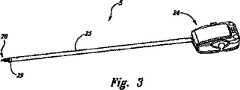
図3は、連接された外科手術用道具または機器5の斜視図を示す。道具5は、近位筐体24を有しており、道具ホルダまたはマニピュレータの機器インターフェースと接合し、概して、無菌アダプタまたはインターフェースを通して載嵌状態の瞬時解放を提供する。その実施例は、2005年12月20日出願の米国特許出願第11/314,040号、および2006年3月31日出願の米国特許出願第11/395,418号に開示されており、あらゆる目的において参照することによって本願に援用される。道具5は、近位筐体24に対し先端部28を支持する細長いシャフト23を含む。近位筐体24は、マニピュレータ8と先端部28との間の駆動信号および駆動動作を送受信する。連接されたリスト29は、先端部28とシャフト23との間の動作に対し自由度2を提供し、シャフトは、シャフトの軸周囲の近位筐体24に対し回動自在にし、先端部28に患者の体内で配向自由度3を提供してもよい。 FIG. 3 shows a perspective view of the articulated surgical tool or
外科手術用道具は、ワイヤ連結、偏心カム、プッシュロッド、または他の機構によって駆動し得る鉗子、鋏、把持装置、持針器、マイクロダイセクタ、ステープルアプライヤ、タッカー、吸引洗浄道具、およびクリップアプライヤ等、種々の連接された先端部を含んでもよい。さらに、外科手術用道具は、切刃、プローブ、洗浄器、カテーテル、または吸引口等、非連接された機器を備えてもよい。別様に、外科手術用道具は、細胞を剥離、切除、切除、または凝固するための電気外科手術用プローブを備えてもよい。適用可能なアダプタ、道具、または機器、および付属品の実施例は、米国特許第6,331,181号、第6,491,701号、および第6,770,081号に記載されており、その全開示(参照することによって援用される開示を含む)は、あらゆる目的において参照することによって本願に援用される。また、適用可能な外科手術用機器は、米国カリフォルニア州サニーベールにあるIntuitive Surgica1,Inc.から市販されている。 Surgical tools include forceps, scissors, grasping devices, needle holders, microdissectors, staple appliers, tuckers, suction cleaning tools, and clips that can be driven by wire connections, eccentric cams, push rods, or other mechanisms Various articulated tips such as an applier may be included. Further, the surgical tool may comprise a non-connected device such as a cutting blade, probe, irrigator, catheter, or suction port. Alternatively, the surgical tool may comprise an electrosurgical probe for detaching, excising, excising, or coagulating cells. Examples of applicable adapters, tools or equipment, and accessories are described in US Pat. Nos. 6,331,181, 6,491,701, and 6,770,081, The entire disclosure (including the disclosure incorporated by reference) is hereby incorporated by reference for all purposes. Applicable surgical instruments are available from Intuitive Surgica 1, Inc., Sunnyvale, California. Commercially available.
図4を参照すると、手術室の天井に搭載され得る、代替モジュール式マニピュレータ支持アセンブリ30の斜視図が示される。モジュール式マニピュレータ支持部30は、患者の体内の1組の所望の外科手術用切開部位に対し、ロボットマニピュレータシステムを配列および支持する。モジュール式マニピュレータ支持部30は、概して、配向プラットフォーム36および配向プラットフォームに結合し得る複数の構成可能な設定連結部アーム38、40、42、44を含む。各アームは、付随マニピュレータ32、34を移動調整可能に支持し、それによって、付随道具または撮像装置を移動調整可能に支持する。また、配向プラットフォーム36は、設定、機器変更、処置の観察等に使用され得るアシスタントディスプレイ104を支持する。モジュール式マニピュレータ支持アセンブリ30の構成要素のいずれかの構造および使用は、マニピュレータシステム6に関する上述のものと類似しており、同時係属出願である2005年1月24日出願の米国特許出願第11/043,688号「Modu1ar Manipu1ator Support For Robotic Surgery」により完全に記載され、その全開示は、参照することによって本願に援用される。上記に概説したように、モジュール式マニピュレータ支持部30の各マニピュレータ32、34もまた挿入軸100を含んでもよい。 Referring to FIG. 4, a perspective view of an alternative modular manipulator support assembly 30 that may be mounted on the operating room ceiling is shown. Modular manipulator support 30 aligns and supports the robotic manipulator system for a set of desired surgical incisions in the patient's body. The modular manipulator support 30 generally includes an orientation platform 36 and a plurality of configurable setting connection arms 38, 40, 42, 44 that can be coupled to the orientation platform. Each arm supports the associated manipulators 32 and 34 so as to be movable, and thereby supports the associated tool or the imaging device so as to be movable. The orientation platform 36 also supports an
図5A−5E1を参照すると、本発明の実施形態に従って、伸縮自在の挿入軸100を含むマニピュレータ8がより詳細に示される。本発明の挿入軸は、3つの連結部を含む3段階の伸縮自在線形軸から成り、一実施例では、軸受、レール、滑車、およびケーブルを介して、互いに移動調整可能に結合され、近位連結部から遠位連結部へ幅が狭くなる連結部または移動する形状因子を有する。有利には、本発明は、片手ポートおよび片手での機器のクラッチ操作、より広い動作範囲、より幅狭の挿入アーム、より優れた挿入軸の剛性および強度を提供し、挿入深度に応じて慣性を減少させ、それによって、単一の設定で2つの四半部外科手術(例えば、結腸直腸外科手術)を可能にし、より広い空間および手術野に近い可視性を提供することを可能にする。 Referring to FIGS. 5A-5E1, a
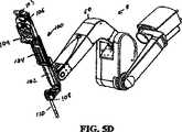
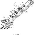
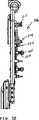
図5A−5Eおよび5B1−5E1は、マニピュレータアーム50と、本発明の実施形態によるアーム50の遠位端に協働しうるように結合された伸縮自在の挿入軸100とを含むマニピュレータ8の斜視図および各側面図を示す。伸縮自在の挿入軸100は、第1の連結部または基礎連結部102、基礎連結部102に協働しうるように結合された第2の連結部または遊動連結部104、および遊動連結部104に協働しうるように結合された第3の連結部または搬送連結部106を含む。 5A-5E and 5B1-5E1 are perspective views of the
基礎連結部102は、マニピュレータアーム50の遠位端に協働しうるように結合され、一実施例では、基礎連結部102の遠位端に取設された付属クランプ108を有する。カニューラ等の付属部110は、付属クランプ108上に搭載されてもよい。適用可能な付属クランプおよび付属品の実施例は、2005年9月30日出願の係属中の米国出願第11/240,087号において開示されており、その全開示は、あらゆる目的において参照することによって本願に援用される。適用可能な無菌アダプタおよび機器筐体の実施例は、2005年12月20日に出願の米国出願第11/314,040号、2006年3月31日出願の米国出願第11/395,418号において開示されており、その全開示は、あらゆる目的において参照することによって本願に援用される。 The
搬送連結部106は、機器無菌アダプタ(ISA)109と協働しうるように結合するための機器インターフェース101を含み、機器の筐体(例えば、図3および5の筐体24)に協働しうるように結合することが可能であり、患者内の機器の深度を制御する。一実施形態では、無菌アダプタは、ロボット外科手術システム、特にマニピュレータシステムを覆い得るドレープと統合され、非殺菌PSMアームと外科的処置の無菌領域との間の無菌バリアを確立する。適用可能なドレープおよびアダプタの実施例は、2005年9月30日に出願の係属中の米国出願第11/240,113号において開示されており、その全開示は、あらゆる目的において参照することによって本願に援用される。 The
誘動連結部104は、基礎連結部102と搬送連結部106との間に移動調整可能に結合され、連結部102、104、および106は、縦方向軸に沿って(例えば、軸C)伸縮自在な方法で互いに対し移動可能となる。一実施形態では、連結部102は、連結部104よりも幅の狭い形状因子を有し、連結部104は、連結部106よりも幅の狭い形状因子を有し、よって手術野に近いより優れた可視性を提供する。 The
マニピュレータ8の軸CからGに沿った動作は、図5Aおよび5A1に示されるように、少なくとも本発明による近位と遠位連結部との間に懸架するケーブルによって提供される。よって、ロボットアームは、アームに協働しうるように結合された道具または機器を制御することが可能になる。ケーブル30は、駆動滑車、車地、遊動滑車、および/または出力滑車も含む、伝送システムの構成要素であり、電気モータによって駆動される。滑車台は、マニピュレータシステム6の挿入軸100とマニピュレータアーム50との間のケーブルおよび電気ワイヤを通すための基礎連結部102の下部に位置する。他の要素に加え、複数の動作両面間接続端子を、動作を伝送するために提供してもよい。 Movement along the axis C to G of the
さらに、駆動アセンブリは、アームと回動するためにそこに結合された複数の駆動モータを含んでもよい。ヨーおよびピッチモータは、それぞれA軸およびB軸(図5A)周囲のアームの動作を制御し、駆動モータは、リストユニットの動作および挿入位置を制御する。一実施形態では、4つの駆動モータは、アーム内に近位に搭載され、アーム上に遠位に搭載された道具の4自由度(D、E、F、およびG軸)を制御する。また、近位に搭載されたモータは、アーム上の道具の挿入位置を遠位に制御する(C軸に沿って)。駆動モータは、好ましくは、エンコーダおよび電位差計(図示せず)に結合され、サーボ機構を有効にする。駆動アセンブリ、アーム、および他の適用可能な部品の実施形態は、例えば、米国特許第6,331,181号、第6,491.701号、第6,770.081号に記載されており、その全開示(参照することによって援用される開示を含む)は、あらゆる目的において参照することによって本願に援用される。また、マニピュレータアームおよび駆動アセンブリは、多様な位置調整装置と使用してもよい。遠隔中央位置調整装置のより完全な説明は、1995年7月20日出願の米国特許出願第08/504,301号、現在は米国特許第5,931,832号において参照可能であり、全開示は、あらゆる目的において参照することによって本願に援用される。 Further, the drive assembly may include a plurality of drive motors coupled thereto for pivoting with the arm. The yaw and pitch motors control the operation of the arms around the A and B axes (FIG. 5A), respectively, and the drive motor controls the operation and insertion position of the wrist unit. In one embodiment, the four drive motors are mounted proximally within the arm and control the four degrees of freedom (D, E, F, and G axes) of the tool mounted distally on the arm. A proximally mounted motor also controls the insertion position of the tool on the arm distally (along the C axis). The drive motor is preferably coupled to an encoder and potentiometer (not shown) to enable the servomechanism. Embodiments of drive assemblies, arms, and other applicable components are described, for example, in US Pat. Nos. 6,331,181, 6,491.701, 6,770.081, The entire disclosure (including the disclosure incorporated by reference) is hereby incorporated by reference for all purposes. The manipulator arm and drive assembly may also be used with a variety of position adjustment devices. A more complete description of the remote central positioning device can be found in US patent application Ser. No. 08 / 504,301 filed Jul. 20, 1995, now US Pat. No. 5,931,832, the entire disclosure Is incorporated herein by reference for all purposes.
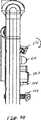
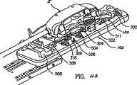
図6A−6Eを参照すると、本発明の実施形態に従って、機器無菌アダプタ、そして最終的には機器(例えば、機器5)を受設するための搬送連結部106の機器インターフェース101を示す斜視図が図示される。機器インターフェース101は、電気接触部510(例えば、偶然の接触から)を絶縁するためのシュラウド502、前負荷をISAディスクに提供するためのスプリング荷重入力部504(各入力部はトルクを外科手術用機器に送達するための突起505を有する)、前負荷をISAのリトラクタプレートに提供するためのスプリングプランジャ506、所定の位置にISA109を保持するためのブラケット508、ISAを固定/解放するためのレバー511、およびロボットマニピュレータに対し無菌アダプタの位置を固定するためにも使用される基準点512を含む。一実施例では、機器インターフェース101は、4つのスプリング荷重入力部504を含み、各入力部は、2つの突起505、4つのスプリングプランジャ506、7つの電気接触部510を有する。 Referring to FIGS. 6A-6E, there is a perspective view showing the
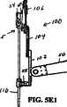
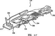
図7A−7Dを参照すると、搬送連結部は、本発明の実施形態による搬送連結部の残りの部分とは分離される機器インターフェースカバー101aを有して図示されている。本発明は、コンパクトな器具および方法を提供し、外科手術用ロボットの出力端部上の機器インターフェース構成要素を効率的にパッケージングする。これらの構成要素は、回路基板、ケーブル伝送要素、センサ、およびレバーを含むがこれらに限定されない。図7Aは、搬送連結部106の機器インターフェースカバー101aおよび内部の機器インターフェース構成要素101bを示す。カバー101aは、基準点512、電気接触部510のための開口部522を備えるシュラウド502、搭載ブラケット508、レバー511のための開口部520、スプリングプランジャ506のための開口部524、およびスプリング荷重入力部504のための開口部526を含む。機器インターフェースのためのこの「クラムシェル」またはカバー設計によって、必要に応じて、内部機構、回路基板、および挿入軸のケーブル伝送要素に容易にアクセスが可能となる。 Referring to FIGS. 7A-7D, the transport connector is illustrated as having an equipment interface cover 101a that is separated from the rest of the transport connector according to an embodiment of the present invention. The present invention provides a compact instrument and method for efficiently packaging instrument interface components on the output end of a surgical robot. These components include, but are not limited to, circuit boards, cable transmission elements, sensors, and levers. FIG. 7A shows the device interface cover 101a and the internal device interface component 101b of the
また、図7A−7Cは、プリント回路アセンブリ(PCA)516に協働しうるように搭載された電気接触部510およびホール効果センサ514を示す。電気接触部510は、ISA109とPCAとの間に電気信号を通すためのインターフェースを提供し、一実施例では、「ポゴピン」を含んでもよい。一実施形態では、遠隔PCA516は、電源の提供および/またはLEDとの連通を提供するための入出力部、ホール効果センサ、無菌アダプタ、機器、およびユーザインターフェースボタン(例えば、クラッチ操作のため)を有してもよい。また、遠隔PCA516は、電源を受けるための入力部および主PCA(例えば、図1のプロセッサ4)と連通するための入出力部を含んでもよい。一実施形態では、主PCAは、電源の供給および/またはモータとの連通(例えば、主PCAは、位置制御をモータに伝送し、電位計およびエンコーダ信号を処理する)のための入力部および出力部、センサ、ユーザインターフェースボタン、遠隔PCA、およびシリアル通信バスを介した患者側カートシステム上の他のプリント回路基板を有してもよい。適用可能なPCAの入出力部の実施例は、2006年12月20日出願の米国出願第_______号(代理人整理番号M−16315−5 US)「Wire1ess Communication In A Robotic Surgica1 System」に記載されており、その全開示は、あらゆる目的において参照することによって本願に援用される。遠隔PCFLは、一実施例では、Embedded Seria1izer for Instrument Interface(ESII)PCAを含んでもよく、主PCAは、一実施例では、Embedded Seria1izer Patient Manipu1ator(ESPM)PCAを含んでもよく、両方とも米国カリフォルニア州サニーベールにあるIntuitive Surgica1, Inc.から入手可能である。 7A-7C also show
ホール効果センサ514は、強固な手段および方法を提供するために使用され、ISA109上に搭載された機器の存在を検出する。ホール効果センサは、可動部がない固体装置であるため望ましい。図7Aおよび7Cは、保護カバーのないホール効果センサ514を示し、図7Bは、保護カバーのあるホール効果のセンサ514の側面図を示す。一実施形態では、2つの隣接するホール効果センサを使用して、機器シャーシ内の磁石の存在下で状態を変化させてもよい。機器磁石がホール効果センサに近接近すると、センサの電気出力状態が変化する。PCA516は、センサの状態変化を検出し、機器が搭載されているシステムに通知する。また、PCA516は、存在検出回路を介して、ISAまたは機器等の存在等、他のシステム構成要素を検出可能にしてもよい。
別の実施例では、ホール効果センサに加え、搭載されている機器が認知するため、システムに第3の入力部が必要となる場合がある。ホール効果センサ514の出力部は、電気回路(例えば、ループバック回路)と連動して使用し、機器の存在下で閉鎖し、それによって冗長化存在確認を提供してもよい。PCA516も同様に、この回路の閉鎖を検出する。図7Dは、ISAを固定/解放するためのレバー511を示す。レバー511は、レバー本体511aおよびレバー本体511aがその周囲を回動し得るシャフト511cを搭載するための搭載ネジ511bを含む。ねじりバネ511eおよび堅固な停止部511dは、ISAが設置または除去されていて、ISAが搭載され、回動位置にある場合、レバー本体511を静止「直立」位置に置く作用をする。レバー本体511aは、水平線から約25度下方へ回動してもよい。図8Aおよび8Bは、レバー511がそれぞれ静止位置および回動位置にある場合を示す。 In another embodiment, a third input may be required in the system because the installed device recognizes in addition to the Hall effect sensor. The output of the
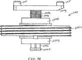
図9A−9Eは、本発明の実施形態による分離した機器入力部504の異なる図を示し、図10A−10Bは、機器入力部の横断面図を示す。図9A、9B、および9Dは、静止(延在)位置にある入力部504を示し、図9Cおよび9Eは、格納位置にある入力部504を示す。入力部504は、スプリング504a、ラジアルボール軸受504b、出力滑車504c、線形ボールスプラインスライドユニット504d、ボールスプライン軸504e、ネジ504f、および突起505を備える入力バー504gを含む。また、線形スライド、v−ローラ、スライドブッシング、ボールネジ等、他の手段を使用して、線形動作およびトルク伝送を達成してもよい。 9A-9E show different views of the separated
スプリング504aは、シャフト504eの軸方向にスプリング力(軸荷重)(図9Dの両方向矢印によって示される)を提供し、それによって、入力バー504gが軸方向に線形に平行移動することが可能となる。ラジアルボール軸受504bは、シャフト504eの縦(または、縦方向)軸周囲におけるアセンブリの回動運動を可能にし、線形ボールスプラインスライドユニット504dは、アセンブリの回動運動、特にシャフト504eの回動運動、従って入力バー504gを支持し、ISAディスク304を介して出力滑車504cからのトルクを機器に伝送可能にする(図12A)。一実施例では、ボールスプラインスライドユニット504dは、出力滑車に挟持され、スプライン軸504eの運動方向における回転要素として作用するボールを再循環する2つのトラックを含む。出力滑車504cは、ケーブルによって駆動し、2006年12月20日出願の米国出願第________号(代理人整理番号 M−16315−1 US)「Cab1e Tensioning In A Robotic Surgica1 System」に開示されており、その全開示(参照することによって援用されるすべての参照文献を含む)は、あらゆる目的において参照することによって以前に本願に援用されている。一実施例では、スプライン軸504eは、再循環ボールが載置される長さに沿って、2つの溝を含む。ネジ504fは、スプライン軸504eに螺入され、軸方向に堅固な停止部を提供する。入力バー504gは、スプライン軸504e上に圧着され、一実施例では、無菌アダプタディスク内の孔に係合する突起505を提供する。The spring 504a provides a spring force (axial load) (indicated by the double arrow in FIG. 9D) in the axial direction of the
図11A−11Bは、本発明の実施形態によるスプリングプランジャの側面図である。図11Bは、静止(延在)位置にあるスプリングプランジャ506を示し、図11Cは、ISA109のリトラクタプレートに対し偏向を提供する際の、格納位置にあるスプリングプランジャ506を示す。 11A-11B are side views of a spring plunger according to an embodiment of the present invention. FIG. 11B shows the
スプリング荷重入力部504、スプリングプランジャ506、およびレバー511は、マニピュレータ上にスプリング要素を提供し、それによって、ISAおよび無菌バリアのための使い捨て可能な設計を可能にする。有利には、マニピュレータおよびISAの設置および係合によって、使用がより簡単になり、より信頼性が高く、労力が少なくなる一方で、ISAおよび無菌バリアドレープのための費用効率の高く、使い捨て可能な設計を可能にする。
図12A、12B、および12Cを参照すると、それぞれ本発明の実施形態によるISA109の上面斜視図、底面斜視図、および断面図が示される。ISA109は、筐体302、ディスク304、リトラクタ上プレート306、筐体302の機器停止機構308、筐体302のレール機構301、接触部310、およびリトラクタ下プレート312を含む。リトラクタ上プレート306およびリトラクタ下プレート312は、リトラクタプレートアセンブリ313を形成し、筐体302に対し移動する。ディスク304は、リトラクタプレートアセンブリ313内に格納され、リトラクタプレートアセンブリに対し移動する。 Referring to FIGS. 12A, 12B, and 12C, there are shown a top perspective view, a bottom perspective view, and a cross-sectional view, respectively, of an
図13は、接触部310の拡大断面図を示し、一実施形態における筐体に挿入生成される。 FIG. 13 shows an enlarged cross-sectional view of the
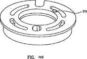
図14Aおよび14Bは、それぞれディスク304の拡大斜視上面および底面図を示し、本発明の実施形態による歯部314をディスク304の基礎部に、外科手術用機器5のピン253を受容するための孔316(図16Dおよび16E参照)をディスク304の本体内に、スプリング荷重入力部504の突起505を受設するための孔317をディスク304の底面(図9および10参照)に、死角からディスク304を移動するためのタブ315を含む。本実施形態では、ISA109は、4つのディスク304を含み、各ディスク304は、4つの歯部314および2つの孔316を含む。4つの歯部314は、一実施形態では、90度離れて載置される。他の実施形態では、多かれ少なかれディスク、歯部、およびスロットが可能であるが、マニピュレータ上のアダプタ受設部分および外科手術用機器と協働しうるように結合する必要があることは留意されたい。 14A and 14B show an enlarged perspective top and bottom view, respectively, of the
図15Aおよび15Bは、本発明の実施形態によるリトラクタ上プレート306の上面および底面斜視図を示す。リトラクタ上プレート306は、相対位置に応じて、ディスク304の歯部314と嵌合させるための機器シャーシ24と歯部319を係合するバー318を含む。図示されるように、リトラクタ上プレート306は、4つのディスク304に対し4つの開口部307を含む。 15A and 15B show top and bottom perspective views of a retractor
図16Aから16Fを参照すると、本発明の実施形態による機器無菌アダプタ(ISA)109の機器インターフェース101(図16A)への設置/係合、外科手術用機器5のISA109への設置/係合(図16B−16E)、およびISA109からの外科手術用機器の除去(図16F)が示される。 Referring to FIGS. 16A-16F, installation / engagement of an instrument aseptic adapter (ISA) 109 to the instrument interface 101 (FIG. 16A), installation / engagement of the
図16Aは、マニピュレータ8のアダプタ受設部分101に設置および係合されたISA109を示す。ISA接触部310は、マニピュレータ接触部510に結合され、ディスク304は、スプリング荷重入力部504に係合され、リトラクタ下プレート312は、スプリングプランジャ506に係合され、および舌機構305(図16Aおよび16F)は、ブラケット508と嵌合する。機器停止機構308によって、機器をISA上に設置する際にユーザがレール301から外れた場合に、機器を停止することが可能となる(患者の安全性のため)。設置の際、機器は、リトラクタ上プレート306上のバー318によって完全に停止する。設置前は、スプリング荷重入力部504およびスプリングプランジャ506は、最も延在した位置にあり、ISAのディスク304は、リトラクタプレートアセンブリ内の任意の位置で回動自在である。一実施形態では、ISA109をインターフェース101のアダプタ受設部分上に設置するため、ユーザは、ISA筐体の舌部をブラケット内に載置し、後端を下方に旋回し、それによって、レバー/ラッチ511を係合する。 FIG. 16A shows the
この設置されてはいるが係合前の位置では、ディスク304は、スプリング荷重入力部504によってリトラクタ上プレート306に対し上方へ圧接され、リトラクタプレートアセンブリ313は、スプリング荷重入力部504およびスプリングプランジャ506によって上方へ圧接される。各ディスク位置(リトラクタプレート306の開口部307)では、リトラクタプレート306上に1つの歯部319があり、ディスク304の歯部314と係合する。歯部の構成は、複数の機能を有しており、その1つは、360度完全に回動しないため、ディスク304の底部の孔317がスプリング荷重入力部504の突起505と嵌合することが不可能な位置にある角度方向である「死角」の外にディスク304を押動することである。歯部の構成の他の機能は、無菌アダプタ係合配列の際に、ディスク304が90度を超えて回動することを防止することである。 In this installed but pre-engaged position, the
係合配列の際、ディスク歯部314は、リトラクタプレート歯部319と噛合することによって、スプリング荷重入力部504を作動させ、突起505とディスク304の底面との間の摩擦およびタブ315との接触を通して、ディスク304の動きを伝える。スプリング荷重入力部504が回動方向を反転させる場合、4つの歯部314の存在によって、ディスク304のこの回動運動が停止し、突起505によって、ディスク304の孔317と列設することが可能となり、スプリング荷重入力部504は、ディスク304に対し回動する。ディスク304の底面上の孔317およびスプリング荷重入力部504の突起505が整合すると、ディスク304は、スプリング荷重入力部504上に落下する。この時、リトラクタ上プレート306の歯部319がディスク304の歯部314を通過し、ディスク304が降下し、それによって、ディスク304がリトラクタプレート306に対し自由に移動することが可能となる。ディスク304がスプリング荷重入力部504上に係合されると、ISA109は、アダプタ受設部分101と係合する。 During the engagement arrangement, the
一実施形態では、係合配列は、アダプタ受設部分101上へのISA109の設置後のミリ秒の間に生じる。ISA109は、所定の位置へ下方に旋回するため、電気接触部310は、電気接触部510(例えば、ポゴピン)と係合し、マニピュレータ8上で初めは開放していた回路を閉鎖し、ISA係合配列を作動させる。筐体302内に挿入成形された接触部310は、複数の電気パス(バイアス)を有し、アダプタ受設部分101上の接触部と係合し、機器電気接触部255を介して外科手術用機器5との連通を確立するために使用してもよいことは留意されたい(図16Cおよび16D)。 In one embodiment, the engagement arrangement occurs during milliseconds after installation of the
図16Bは、部分的に設置された外科手術用機器5を示し、図16Cは、ISA109に完全に設置および係合された外科手術用機器5を示す。初めに、ユーザは、外科手術用機器5をISA109上に設置するため、リトラクタプレートアセンブリ313は、アダプタ受設部分101へ下方に押動され、リトラクタ上プレート306は、中央バー318を係合する機器5によって下方へ圧接される。機器5とISA109との間の電気係合15の前に、バー318上の角面は、機器5の底面上の角面と係合し、これらの2つの角面が整合すると、機器は、スプリング荷重入力部およびスプリングプランジャのスプリング力のため、定位置へ抜脱される。機器が定位置へ抜脱されると、リトラクタプレートアセンブリ313は、外科手術用機器内へ上昇を開始し、実質的に同一動作で、機器5の電気接触部255は、ISA109の電気接触部310と接触する。機器5がISA109上に設置される場合、リトラクタ上プレート306は、機器の底面上で圧接し、バー318は、機器筐体内の空間スロット内にある。機器上の入力部がディスク304の上面上の孔316と係合しないため、機器の係合前に、ディスク304およびスプリング荷重入力部504は、機器から離れて圧接される。 FIG. 16B shows the
図16Dおよび16Eは、ディスク304の機器5との係合配列を示す。図16Dでは、ディスク304が回動し、初めは任意の位置にある機器ディスク251と整合するまで、ディスク304は、機器5と係合されない。ISA109とアダプタ受設部分101との間の係合配列に関して上述したように、機器の電気接触部はISA109の接触部310と係合するため、通常ESIIプリント回路基板と機器との間で開放している回路は、ISAを通して閉鎖され、機器係合配列を作動する。スプリング荷重入力部504およびディスク304は、ディスク304の孔316が機器ディスク251のピン253と係合するまで、アセンブリとして一体となって回動する。孔がピンと整合すると、ディスク304およびスプリング荷重入力部504は、上方へ移動可能となる。図16Eは、ISAディスク304の孔316と係合するピン253を有する機器ディスク251を示す。この時、機器5は、ISA109と係合していると考えられる。ISA109上の他の接触部が、外科手術システムと機器「休止可能ツールインターフェース」(Reposab1e Too1 Interface;RTI)基板との間の電気信号を伝送してもよいことは留意されたい。 16D and 16E show the engagement arrangement of the
機器が完全に設置されると、その筐体に沿った3つの地点で所定の位置に保持される。2つの地点は、機器の側面に沿ったレール機構301にあり、第3の地点は、機器の正面中央に沿った中央押下タブ309にある。有利には、機器を3つの位置で押下することによって、機器は過度に拘束されず、設置および除去が容易となる。 When the device is fully installed, it is held in place at three points along its housing. Two points are in the
図16Fは、機器5(図示せず)のISA109からの除去を示す。ユーザが機器の除去を望む場合、機器シャーシのいずれかの側面上のレバーが圧搾され、機器がISAから抜脱される。機器上のレバーが、リトラクタ上プレートの中央バー318に作用し、それによって、リトラクタプレートを機器から離れて下方へ押動される。リトラクタプレートがさらに離れることによって、ディスク304は機器のピンから係脱され、機器の除去が可能となる。 FIG. 16F shows the removal of instrument 5 (not shown) from
上述の実施形態は、本発明を説明するものであって、限定するものではない。本発明の原理に従って、多くの修正および変形が可能であることも理解されたい。例えば、本システムは、4つのロボットマニピュレータアセンブリに制限されるものではなく、他の実施例において2つ以上を含んでもよい。したがって、本発明の範囲は、以下の請求項によってのみ定義される。 The above-described embodiments are illustrative of the invention and are not limiting. It should also be understood that many modifications and variations are possible in accordance with the principles of the present invention. For example, the system is not limited to four robotic manipulator assemblies and may include more than one in other embodiments. Accordingly, the scope of the invention is defined only by the following claims.
Claims (17)
Translated fromJapanese機器を動作可能に結合するように構成された無菌アダプタに軸方向の荷重およびトルクを提供する入力部と、
前記無菌アダプタの第1の端部を保持する搭載ブラケットと、
偏向レバー本体を用いて前記無菌アダプタの第2の端部を着脱する解放レバーと
を含み、
前記入力部は、
出力滑車に動作可能に結合されたシャフトに結合された入力バーと、
前記入力バーに対して前記シャフトの軸方向にスプリング力を提供するように構成されたスプリングと
を含む、機器インターフェース。An integrated device interface of a robot manipulator, wherein the device interface is
An input portionconfigured sterile adapterto operatively couple devicesthat provide load and torquethe axialdirection,
A mounting bracket for holding the first end of the sterile adapter;
A release lever for attaching and detaching the second end of the sterile adapter using a deflection lever body;
Including
The input unit is
An input bar coupled to a shaft operably coupled to the output pulley;
A spring configured to provide a spring force in an axial direction of the shaft against the input bar;
Including device interface.
マニピュレータアームの遠位端に動作可能に結合された基礎連結部と、
縦方向軸に沿って前記基礎連結部に移動可能に結合された搬送連結部と
を含むマニュピレータアセンブリであって、
前記搬送連結部は、統合された機器インターフェースを含み、
前記統合された機器インターフェースは、
機器を動作可能に結合するように構成された無菌アダプタに軸方向の荷重およびトルクを提供する入力部と、
前記無菌アダプタの第1の端部を保持する搭載ブラケットと、
偏向レバー本体を用いて前記無菌アダプタの第2の端部を着脱する解放レバーと
を有し、
前記入力部は、
出力滑車に動作可能に結合されたシャフトに結合された入力バーと、
前記入力バーに対して前記シャフトの軸方向にスプリング力を提供するように構成されたスプリングと
を含む、マニュピレータアセンブリと、
前記機器インターフェースを介して前記搬送連結部に動作可能に結合された機器と、
前記マニピュレータアセンブリに動作可能に結合されたプロセッサであって、前記機器の存在を検出するためのプロセッサと
を含む、システム。A robotic surgical manipulator systemcomprising:
A base connection operably coupled to the distal endof the manipulator arm;
A transport coupling portionmovably coupled to the foundation coupling portion along a longitudinal axis;
A manipulator assembly comprising:
The transport connection includes anintegrated device interface;
The integrated device interface is:
An input portionconfigured sterile adapterto operatively couple devicesthat provide load and torquethe axialdirection,
A mounting bracket for holding the first end of the sterile adapter;
A release lever for attaching and detaching the second end of the sterile adapter using a deflection lever body;
Have
The input unit is
An input bar coupled to a shaft operably coupled to the output pulley;
A spring configured to provide a spring force in an axial direction of the shaft against the input bar;
Including a manipulator assembly;
Andoperatively coupled device to the carriage link via the device interface,
And a processoroperably coupled tothe manipulatorassembly, and aprocessor for detecting the presence of the device, system.
Applications Claiming Priority (7)
| Application Number | Priority Date | Filing Date | Title |
|---|---|---|---|
| US75275505P | 2005-12-20 | 2005-12-20 | |
| US11/314,040 | 2005-12-20 | ||
| US60/752,755 | 2005-12-20 | ||
| US11/314,040US7666191B2 (en) | 1996-12-12 | 2005-12-20 | Robotic surgical system with sterile surgical adaptor |
| US11/613,695 | 2006-12-20 | ||
| PCT/US2006/048744WO2007075864A1 (en) | 2005-12-20 | 2006-12-20 | Instrument interface of a robotic surgical system |
| US11/613,695US7963913B2 (en) | 1996-12-12 | 2006-12-20 | Instrument interface of a robotic surgical system |
Related Child Applications (1)
| Application Number | Title | Priority Date | Filing Date |
|---|---|---|---|
| JP2012064143ADivisionJP5283241B2 (en) | 2005-12-20 | 2012-03-21 | Equipment interface for robotic surgery system |
Publications (2)
| Publication Number | Publication Date |
|---|---|
| JP2009520573A JP2009520573A (en) | 2009-05-28 |
| JP5101519B2true JP5101519B2 (en) | 2012-12-19 |
Family
ID=39665967
Family Applications (2)
| Application Number | Title | Priority Date | Filing Date |
|---|---|---|---|
| JP2008547535AActiveJP5101519B2 (en) | 2005-12-20 | 2006-12-20 | Equipment interface for robotic surgery system |
| JP2012064143AActiveJP5283241B2 (en) | 2005-12-20 | 2012-03-21 | Equipment interface for robotic surgery system |
Family Applications After (1)
| Application Number | Title | Priority Date | Filing Date |
|---|---|---|---|
| JP2012064143AActiveJP5283241B2 (en) | 2005-12-20 | 2012-03-21 | Equipment interface for robotic surgery system |
Country Status (7)
| Country | Link |
|---|---|
| US (1) | US7963913B2 (en) |
| EP (1) | EP1962711B1 (en) |
| JP (2) | JP5101519B2 (en) |
| KR (1) | KR101337278B1 (en) |
| CN (1) | CN101340852B (en) |
| AT (1) | ATE547059T1 (en) |
| WO (1) | WO2007075864A1 (en) |
Families Citing this family (732)
| Publication number | Priority date | Publication date | Assignee | Title |
|---|---|---|---|---|
| US8206406B2 (en) | 1996-12-12 | 2012-06-26 | Intuitive Surgical Operations, Inc. | Disposable sterile surgical adaptor |
| US6331181B1 (en)* | 1998-12-08 | 2001-12-18 | Intuitive Surgical, Inc. | Surgical robotic tools, data architecture, and use |
| US8529582B2 (en) | 1996-12-12 | 2013-09-10 | Intuitive Surgical Operations, Inc. | Instrument interface of a robotic surgical system |
| US7666191B2 (en) | 1996-12-12 | 2010-02-23 | Intuitive Surgical, Inc. | Robotic surgical system with sterile surgical adaptor |
| US8182469B2 (en) | 1997-11-21 | 2012-05-22 | Intuitive Surgical Operations, Inc. | Surgical accessory clamp and method |
| US6132368A (en) | 1996-12-12 | 2000-10-17 | Intuitive Surgical, Inc. | Multi-component telepresence system and method |
| US7727244B2 (en) | 1997-11-21 | 2010-06-01 | Intuitive Surgical Operation, Inc. | Sterile surgical drape |
| US8944070B2 (en) | 1999-04-07 | 2015-02-03 | Intuitive Surgical Operations, Inc. | Non-force reflecting method for providing tool force information to a user of a telesurgical system |
| US8414505B1 (en) | 2001-02-15 | 2013-04-09 | Hansen Medical, Inc. | Catheter driver system |
| US20070084897A1 (en) | 2003-05-20 | 2007-04-19 | Shelton Frederick E Iv | Articulating surgical stapling instrument incorporating a two-piece e-beam firing mechanism |
| US9060770B2 (en) | 2003-05-20 | 2015-06-23 | Ethicon Endo-Surgery, Inc. | Robotically-driven surgical instrument with E-beam driver |
| US8215531B2 (en) | 2004-07-28 | 2012-07-10 | Ethicon Endo-Surgery, Inc. | Surgical stapling instrument having a medical substance dispenser |
| US11896225B2 (en) | 2004-07-28 | 2024-02-13 | Cilag Gmbh International | Staple cartridge comprising a pan |
| US9072535B2 (en) | 2011-05-27 | 2015-07-07 | Ethicon Endo-Surgery, Inc. | Surgical stapling instruments with rotatable staple deployment arrangements |
| US11998198B2 (en) | 2004-07-28 | 2024-06-04 | Cilag Gmbh International | Surgical stapling instrument incorporating a two-piece E-beam firing mechanism |
| US8339447B2 (en)* | 2004-10-21 | 2012-12-25 | Truevision Systems, Inc. | Stereoscopic electronic microscope workstation |
| US7837674B2 (en) | 2005-01-24 | 2010-11-23 | Intuitive Surgical Operations, Inc. | Compact counter balance for robotic surgical systems |
| US7763015B2 (en) | 2005-01-24 | 2010-07-27 | Intuitive Surgical Operations, Inc. | Modular manipulator support for robotic surgery |
| US8945095B2 (en)* | 2005-03-30 | 2015-02-03 | Intuitive Surgical Operations, Inc. | Force and torque sensing for surgical instruments |
| US8375808B2 (en) | 2005-12-30 | 2013-02-19 | Intuitive Surgical Operations, Inc. | Force sensing for surgical instruments |
| US9789608B2 (en)* | 2006-06-29 | 2017-10-17 | Intuitive Surgical Operations, Inc. | Synthetic representation of a surgical robot |
| US8273076B2 (en)* | 2005-06-30 | 2012-09-25 | Intuitive Surgical Operations, Inc. | Indicator for tool state and communication in multi-arm robotic telesurgery |
| KR101298492B1 (en) | 2005-06-30 | 2013-08-21 | 인튜어티브 서지컬 인코포레이티드 | Indicator for tool state and communication in multiarm robotic telesurgery |
| US7934630B2 (en) | 2005-08-31 | 2011-05-03 | Ethicon Endo-Surgery, Inc. | Staple cartridges for forming staples having differing formed staple heights |
| US7669746B2 (en) | 2005-08-31 | 2010-03-02 | Ethicon Endo-Surgery, Inc. | Staple cartridges for forming staples having differing formed staple heights |
| US10159482B2 (en) | 2005-08-31 | 2018-12-25 | Ethicon Llc | Fastener cartridge assembly comprising a fixed anvil and different staple heights |
| US11484312B2 (en) | 2005-08-31 | 2022-11-01 | Cilag Gmbh International | Staple cartridge comprising a staple driver arrangement |
| US9237891B2 (en) | 2005-08-31 | 2016-01-19 | Ethicon Endo-Surgery, Inc. | Robotically-controlled surgical stapling devices that produce formed staples having different lengths |
| US11246590B2 (en) | 2005-08-31 | 2022-02-15 | Cilag Gmbh International | Staple cartridge including staple drivers having different unfired heights |
| US20070188603A1 (en)* | 2005-10-21 | 2007-08-16 | Riederer Thomas P | Stereoscopic display cart and system |
| US8358330B2 (en)* | 2005-10-21 | 2013-01-22 | True Vision Systems, Inc. | Stereoscopic electronic microscope workstation |
| US20070106317A1 (en) | 2005-11-09 | 2007-05-10 | Shelton Frederick E Iv | Hydraulically and electrically actuated articulation joints for surgical instruments |
| WO2007075844A1 (en) | 2005-12-20 | 2007-07-05 | Intuitive Surgical, Inc. | Telescoping insertion axis of a robotic surgical system |
| US9586327B2 (en)* | 2005-12-20 | 2017-03-07 | Intuitive Surgical Operations, Inc. | Hook and pivot electro-mechanical interface for robotic medical arms |
| US8182470B2 (en) | 2005-12-20 | 2012-05-22 | Intuitive Surgical Operations, Inc. | Telescoping insertion axis of a robotic surgical system |
| US11432895B2 (en) | 2005-12-20 | 2022-09-06 | Intuitive Surgical Operations, Inc. | Wireless communication in a robotic surgical system |
| US8672922B2 (en) | 2005-12-20 | 2014-03-18 | Intuitive Surgical Operations, Inc. | Wireless communication in a robotic surgical system |
| US8628518B2 (en) | 2005-12-30 | 2014-01-14 | Intuitive Surgical Operations, Inc. | Wireless force sensor on a distal portion of a surgical instrument and method |
| US20110290856A1 (en) | 2006-01-31 | 2011-12-01 | Ethicon Endo-Surgery, Inc. | Robotically-controlled surgical instrument with force-feedback capabilities |
| US7845537B2 (en) | 2006-01-31 | 2010-12-07 | Ethicon Endo-Surgery, Inc. | Surgical instrument having recording capabilities |
| US11793518B2 (en) | 2006-01-31 | 2023-10-24 | Cilag Gmbh International | Powered surgical instruments with firing system lockout arrangements |
| US8186555B2 (en) | 2006-01-31 | 2012-05-29 | Ethicon Endo-Surgery, Inc. | Motor-driven surgical cutting and fastening instrument with mechanical closure system |
| US8820603B2 (en) | 2006-01-31 | 2014-09-02 | Ethicon Endo-Surgery, Inc. | Accessing data stored in a memory of a surgical instrument |
| US20110024477A1 (en) | 2009-02-06 | 2011-02-03 | Hall Steven G | Driven Surgical Stapler Improvements |
| US8708213B2 (en) | 2006-01-31 | 2014-04-29 | Ethicon Endo-Surgery, Inc. | Surgical instrument having a feedback system |
| US20120292367A1 (en) | 2006-01-31 | 2012-11-22 | Ethicon Endo-Surgery, Inc. | Robotically-controlled end effector |
| US11224427B2 (en) | 2006-01-31 | 2022-01-18 | Cilag Gmbh International | Surgical stapling system including a console and retraction assembly |
| US11278279B2 (en) | 2006-01-31 | 2022-03-22 | Cilag Gmbh International | Surgical instrument assembly |
| US7753904B2 (en) | 2006-01-31 | 2010-07-13 | Ethicon Endo-Surgery, Inc. | Endoscopic surgical instrument with a handle that can articulate with respect to the shaft |
| US8992422B2 (en) | 2006-03-23 | 2015-03-31 | Ethicon Endo-Surgery, Inc. | Robotically-controlled endoscopic accessory channel |
| CN101500470B (en)* | 2006-06-13 | 2015-03-25 | 直观外科手术操作公司 | Minimally Invasive Surgical System |
| US8322455B2 (en) | 2006-06-27 | 2012-12-04 | Ethicon Endo-Surgery, Inc. | Manually driven surgical cutting and fastening instrument |
| US12357400B2 (en) | 2006-06-29 | 2025-07-15 | Intuitive Surgical Operations, Inc. | Synthetic representation of a surgical robot |
| US10008017B2 (en) | 2006-06-29 | 2018-06-26 | Intuitive Surgical Operations, Inc. | Rendering tool information as graphic overlays on displayed images of tools |
| US10258425B2 (en)* | 2008-06-27 | 2019-04-16 | Intuitive Surgical Operations, Inc. | Medical robotic system providing an auxiliary view of articulatable instruments extending out of a distal end of an entry guide |
| US9718190B2 (en) | 2006-06-29 | 2017-08-01 | Intuitive Surgical Operations, Inc. | Tool position and identification indicator displayed in a boundary area of a computer display screen |
| US20090192523A1 (en) | 2006-06-29 | 2009-07-30 | Intuitive Surgical, Inc. | Synthetic representation of a surgical instrument |
| US8220690B2 (en) | 2006-09-29 | 2012-07-17 | Ethicon Endo-Surgery, Inc. | Connected surgical staples and stapling instruments for deploying the same |
| US10568652B2 (en) | 2006-09-29 | 2020-02-25 | Ethicon Llc | Surgical staples having attached drivers of different heights and stapling instruments for deploying the same |
| US11980366B2 (en) | 2006-10-03 | 2024-05-14 | Cilag Gmbh International | Surgical instrument |
| US8632535B2 (en) | 2007-01-10 | 2014-01-21 | Ethicon Endo-Surgery, Inc. | Interlock and surgical instrument including same |
| US8652120B2 (en) | 2007-01-10 | 2014-02-18 | Ethicon Endo-Surgery, Inc. | Surgical instrument with wireless communication between control unit and sensor transponders |
| US8684253B2 (en) | 2007-01-10 | 2014-04-01 | Ethicon Endo-Surgery, Inc. | Surgical instrument with wireless communication between a control unit of a robotic system and remote sensor |
| US11291441B2 (en) | 2007-01-10 | 2022-04-05 | Cilag Gmbh International | Surgical instrument with wireless communication between control unit and remote sensor |
| US20080169333A1 (en) | 2007-01-11 | 2008-07-17 | Shelton Frederick E | Surgical stapler end effector with tapered distal end |
| US11039836B2 (en) | 2007-01-11 | 2021-06-22 | Cilag Gmbh International | Staple cartridge for use with a surgical stapling instrument |
| US7604151B2 (en) | 2007-03-15 | 2009-10-20 | Ethicon Endo-Surgery, Inc. | Surgical stapling systems and staple cartridges for deploying surgical staples with tissue compression features |
| US8893946B2 (en) | 2007-03-28 | 2014-11-25 | Ethicon Endo-Surgery, Inc. | Laparoscopic tissue thickness and clamp load measuring devices |
| US11564682B2 (en) | 2007-06-04 | 2023-01-31 | Cilag Gmbh International | Surgical stapler device |
| US8931682B2 (en) | 2007-06-04 | 2015-01-13 | Ethicon Endo-Surgery, Inc. | Robotically-controlled shaft based rotary drive systems for surgical instruments |
| US8903546B2 (en) | 2009-08-15 | 2014-12-02 | Intuitive Surgical Operations, Inc. | Smooth control of an articulated instrument across areas with different work space conditions |
| US9089256B2 (en) | 2008-06-27 | 2015-07-28 | Intuitive Surgical Operations, Inc. | Medical robotic system providing an auxiliary view including range of motion limitations for articulatable instruments extending out of a distal end of an entry guide |
| US9469034B2 (en) | 2007-06-13 | 2016-10-18 | Intuitive Surgical Operations, Inc. | Method and system for switching modes of a robotic system |
| US8620473B2 (en) | 2007-06-13 | 2013-12-31 | Intuitive Surgical Operations, Inc. | Medical robotic system with coupled control modes |
| US9138129B2 (en) | 2007-06-13 | 2015-09-22 | Intuitive Surgical Operations, Inc. | Method and system for moving a plurality of articulated instruments in tandem back towards an entry guide |
| US9084623B2 (en) | 2009-08-15 | 2015-07-21 | Intuitive Surgical Operations, Inc. | Controller assisted reconfiguration of an articulated instrument during movement into and out of an entry guide |
| US7753245B2 (en) | 2007-06-22 | 2010-07-13 | Ethicon Endo-Surgery, Inc. | Surgical stapling instruments |
| US11849941B2 (en) | 2007-06-29 | 2023-12-26 | Cilag Gmbh International | Staple cartridge having staple cavities extending at a transverse angle relative to a longitudinal cartridge axis |
| US20090088772A1 (en)* | 2007-09-27 | 2009-04-02 | Blumenkranz Stephen J | Fiber optic in-situ chemical analysis in a robotic surgical system |
| US8400094B2 (en)* | 2007-12-21 | 2013-03-19 | Intuitive Surgical Operations, Inc. | Robotic surgical system with patient support |
| US9179912B2 (en) | 2008-02-14 | 2015-11-10 | Ethicon Endo-Surgery, Inc. | Robotically-controlled motorized surgical cutting and fastening instrument |
| BRPI0901282A2 (en) | 2008-02-14 | 2009-11-17 | Ethicon Endo Surgery Inc | surgical cutting and fixation instrument with rf electrodes |
| US8573465B2 (en) | 2008-02-14 | 2013-11-05 | Ethicon Endo-Surgery, Inc. | Robotically-controlled surgical end effector system with rotary actuated closure systems |
| US7866527B2 (en) | 2008-02-14 | 2011-01-11 | Ethicon Endo-Surgery, Inc. | Surgical stapling apparatus with interlockable firing system |
| US8636736B2 (en) | 2008-02-14 | 2014-01-28 | Ethicon Endo-Surgery, Inc. | Motorized surgical cutting and fastening instrument |
| US8758391B2 (en) | 2008-02-14 | 2014-06-24 | Ethicon Endo-Surgery, Inc. | Interchangeable tools for surgical instruments |
| US7819298B2 (en) | 2008-02-14 | 2010-10-26 | Ethicon Endo-Surgery, Inc. | Surgical stapling apparatus with control features operable with one hand |
| US11986183B2 (en) | 2008-02-14 | 2024-05-21 | Cilag Gmbh International | Surgical cutting and fastening instrument comprising a plurality of sensors to measure an electrical parameter |
| US9585657B2 (en) | 2008-02-15 | 2017-03-07 | Ethicon Endo-Surgery, Llc | Actuator for releasing a layer of material from a surgical end effector |
| US11272927B2 (en) | 2008-02-15 | 2022-03-15 | Cilag Gmbh International | Layer arrangements for surgical staple cartridges |
| US9895813B2 (en)* | 2008-03-31 | 2018-02-20 | Intuitive Surgical Operations, Inc. | Force and torque sensing in a surgical robot setup arm |
| WO2009151205A1 (en)* | 2008-06-11 | 2009-12-17 | (주)미래컴퍼니 | Instrument of surgical robot arm |
| KR100971900B1 (en) | 2008-06-11 | 2010-07-22 | (주)미래컴퍼니 | Instrument of Surgical Robot Arm |
| US12239396B2 (en) | 2008-06-27 | 2025-03-04 | Intuitive Surgical Operations, Inc. | Medical robotic system providing an auxiliary view including range of motion limitations for articulatable instruments extending out of a distal end of an entry guide |
| US8864652B2 (en) | 2008-06-27 | 2014-10-21 | Intuitive Surgical Operations, Inc. | Medical robotic system providing computer generated auxiliary views of a camera instrument for controlling the positioning and orienting of its tip |
| US8916134B2 (en)* | 2008-07-11 | 2014-12-23 | Industry-Academic Cooperation Foundation, Yonsei University | Metal nanocomposite, preparation method and use thereof |
| US9386983B2 (en) | 2008-09-23 | 2016-07-12 | Ethicon Endo-Surgery, Llc | Robotically-controlled motorized surgical instrument |
| US9005230B2 (en) | 2008-09-23 | 2015-04-14 | Ethicon Endo-Surgery, Inc. | Motorized surgical instrument |
| US11648005B2 (en) | 2008-09-23 | 2023-05-16 | Cilag Gmbh International | Robotically-controlled motorized surgical instrument with an end effector |
| US8210411B2 (en) | 2008-09-23 | 2012-07-03 | Ethicon Endo-Surgery, Inc. | Motor-driven surgical cutting instrument |
| US9339342B2 (en) | 2008-09-30 | 2016-05-17 | Intuitive Surgical Operations, Inc. | Instrument interface |
| US9259274B2 (en) | 2008-09-30 | 2016-02-16 | Intuitive Surgical Operations, Inc. | Passive preload and capstan drive for surgical instruments |
| US8608045B2 (en) | 2008-10-10 | 2013-12-17 | Ethicon Endo-Sugery, Inc. | Powered surgical cutting and stapling apparatus with manually retractable firing system |
| US8517239B2 (en) | 2009-02-05 | 2013-08-27 | Ethicon Endo-Surgery, Inc. | Surgical stapling instrument comprising a magnetic element driver |
| US8444036B2 (en) | 2009-02-06 | 2013-05-21 | Ethicon Endo-Surgery, Inc. | Motor driven surgical fastener device with mechanisms for adjusting a tissue gap within the end effector |
| JP2012517287A (en) | 2009-02-06 | 2012-08-02 | エシコン・エンド−サージェリィ・インコーポレイテッド | Improvement of driven surgical stapler |
| US8423182B2 (en) | 2009-03-09 | 2013-04-16 | Intuitive Surgical Operations, Inc. | Adaptable integrated energy control system for electrosurgical tools in robotic surgical systems |
| US12266040B2 (en) | 2009-03-31 | 2025-04-01 | Intuitive Surgical Operations, Inc. | Rendering tool information as graphic overlays on displayed images of tools |
| US20100268250A1 (en)* | 2009-04-17 | 2010-10-21 | Microdexterity Systems, Inc. | Surgical system with medical manipulator and sterile barrier |
| US20100268249A1 (en)* | 2009-04-17 | 2010-10-21 | Microdexterity Systems, Inc. | Surgical system with medical manipulator and sterile barrier |
| US9492927B2 (en) | 2009-08-15 | 2016-11-15 | Intuitive Surgical Operations, Inc. | Application of force feedback on an input device to urge its operator to command an articulated instrument to a preferred pose |
| US8918211B2 (en) | 2010-02-12 | 2014-12-23 | Intuitive Surgical Operations, Inc. | Medical robotic system providing sensory feedback indicating a difference between a commanded state and a preferred pose of an articulated instrument |
| CN104706426A (en)* | 2009-09-23 | 2015-06-17 | 伊顿株式会社 | Sterile adapter, connection structure of wheel and connection structure of surgical instrument |
| US8851354B2 (en) | 2009-12-24 | 2014-10-07 | Ethicon Endo-Surgery, Inc. | Surgical cutting instrument that analyzes tissue thickness |
| US8220688B2 (en) | 2009-12-24 | 2012-07-17 | Ethicon Endo-Surgery, Inc. | Motor-driven surgical cutting instrument with electric actuator directional control assembly |
| US20110282357A1 (en)* | 2010-05-14 | 2011-11-17 | Intuitive Surgical Operations, Inc. | Surgical system architecture |
| US8783543B2 (en) | 2010-07-30 | 2014-07-22 | Ethicon Endo-Surgery, Inc. | Tissue acquisition arrangements and methods for surgical stapling devices |
| US8360296B2 (en) | 2010-09-09 | 2013-01-29 | Ethicon Endo-Surgery, Inc. | Surgical stapling head assembly with firing lockout for a surgical stapler |
| US9232941B2 (en) | 2010-09-30 | 2016-01-12 | Ethicon Endo-Surgery, Inc. | Tissue thickness compensator comprising a reservoir |
| US9629814B2 (en) | 2010-09-30 | 2017-04-25 | Ethicon Endo-Surgery, Llc | Tissue thickness compensator configured to redistribute compressive forces |
| US11925354B2 (en) | 2010-09-30 | 2024-03-12 | Cilag Gmbh International | Staple cartridge comprising staples positioned within a compressible portion thereof |
| US12213666B2 (en) | 2010-09-30 | 2025-02-04 | Cilag Gmbh International | Tissue thickness compensator comprising layers |
| US11812965B2 (en) | 2010-09-30 | 2023-11-14 | Cilag Gmbh International | Layer of material for a surgical end effector |
| US10945731B2 (en) | 2010-09-30 | 2021-03-16 | Ethicon Llc | Tissue thickness compensator comprising controlled release and expansion |
| US9320523B2 (en) | 2012-03-28 | 2016-04-26 | Ethicon Endo-Surgery, Llc | Tissue thickness compensator comprising tissue ingrowth features |
| US8740038B2 (en) | 2010-09-30 | 2014-06-03 | Ethicon Endo-Surgery, Inc. | Staple cartridge comprising a releasable portion |
| US9839420B2 (en) | 2010-09-30 | 2017-12-12 | Ethicon Llc | Tissue thickness compensator comprising at least one medicament |
| US9364233B2 (en) | 2010-09-30 | 2016-06-14 | Ethicon Endo-Surgery, Llc | Tissue thickness compensators for circular surgical staplers |
| US11298125B2 (en) | 2010-09-30 | 2022-04-12 | Cilag Gmbh International | Tissue stapler having a thickness compensator |
| US9566061B2 (en) | 2010-09-30 | 2017-02-14 | Ethicon Endo-Surgery, Llc | Fastener cartridge comprising a releasably attached tissue thickness compensator |
| US8695866B2 (en) | 2010-10-01 | 2014-04-15 | Ethicon Endo-Surgery, Inc. | Surgical instrument having a power control circuit |
| US9342997B2 (en) | 2010-10-29 | 2016-05-17 | The University Of North Carolina At Chapel Hill | Modular staged reality simulator |
| US9805625B2 (en) | 2010-10-29 | 2017-10-31 | KindHeart, Inc. | Surgical simulation assembly |
| US9113883B2 (en) | 2011-03-14 | 2015-08-25 | Ethicon Endo-Surgery, Inc. | Collapsible anvil plate assemblies for circular surgical stapling devices |
| RU2606493C2 (en) | 2011-04-29 | 2017-01-10 | Этикон Эндо-Серджери, Инк. | Staple cartridge, containing staples, located inside its compressible part |
| US11207064B2 (en) | 2011-05-27 | 2021-12-28 | Cilag Gmbh International | Automated end effector component reloading system for use with a robotic system |
| CN103561667B (en)* | 2011-05-31 | 2016-08-17 | 直观外科手术操作公司 | Gripping Force Control in Robotic Surgical Instruments |
| JP6021353B2 (en) | 2011-08-04 | 2016-11-09 | オリンパス株式会社 | Surgery support device |
| JP6009840B2 (en) | 2011-08-04 | 2016-10-19 | オリンパス株式会社 | Medical equipment |
| JP5953058B2 (en) | 2011-08-04 | 2016-07-13 | オリンパス株式会社 | Surgery support device and method for attaching and detaching the same |
| JP5931497B2 (en) | 2011-08-04 | 2016-06-08 | オリンパス株式会社 | Surgery support apparatus and assembly method thereof |
| WO2013018897A1 (en) | 2011-08-04 | 2013-02-07 | オリンパス株式会社 | Surgical implement and medical treatment manipulator |
| JP5841451B2 (en) | 2011-08-04 | 2016-01-13 | オリンパス株式会社 | Surgical instrument and control method thereof |
| JP6000641B2 (en) | 2011-08-04 | 2016-10-05 | オリンパス株式会社 | Manipulator system |
| JP6005950B2 (en) | 2011-08-04 | 2016-10-12 | オリンパス株式会社 | Surgery support apparatus and control method thereof |
| JP5936914B2 (en) | 2011-08-04 | 2016-06-22 | オリンパス株式会社 | Operation input device and manipulator system including the same |
| CN103717169B (en) | 2011-08-04 | 2016-11-16 | 奥林巴斯株式会社 | Medical manipulator and control method thereof |
| WO2013018908A1 (en) | 2011-08-04 | 2013-02-07 | オリンパス株式会社 | Manipulator for medical use and surgery support device |
| JP6021484B2 (en) | 2011-08-04 | 2016-11-09 | オリンパス株式会社 | Medical manipulator |
| JP6081061B2 (en) | 2011-08-04 | 2017-02-15 | オリンパス株式会社 | Surgery support device |
| EP2773277B1 (en) | 2011-11-04 | 2016-03-02 | Titan Medical Inc. | Apparatus for controlling an end-effector assembly |
| WO2013063674A1 (en) | 2011-11-04 | 2013-05-10 | Titan Medical Inc. | Apparatus and method for controlling an end-effector assembly |
| US9044230B2 (en) | 2012-02-13 | 2015-06-02 | Ethicon Endo-Surgery, Inc. | Surgical cutting and fastening instrument with apparatus for determining cartridge and firing motion status |
| BR112014024098B1 (en) | 2012-03-28 | 2021-05-25 | Ethicon Endo-Surgery, Inc. | staple cartridge |
| MX353040B (en) | 2012-03-28 | 2017-12-18 | Ethicon Endo Surgery Inc | Retainer assembly including a tissue thickness compensator. |
| CN104321024B (en) | 2012-03-28 | 2017-05-24 | 伊西康内外科公司 | Tissue thickness compensator comprising a plurality of layers |
| DE102012207707A1 (en)* | 2012-05-09 | 2013-11-28 | Deutsches Zentrum für Luft- und Raumfahrt e.V. | Minimally invasive instrument for robotic surgery |
| US20130317519A1 (en) | 2012-05-25 | 2013-11-28 | Hansen Medical, Inc. | Low friction instrument driver interface for robotic systems |
| EP2854691B1 (en)* | 2012-06-01 | 2021-11-17 | Intuitive Surgical Operations, Inc. | Redundant axis and degree of freedom for hardware-constrained remote center robotic manipulator |
| WO2013181536A1 (en) | 2012-06-01 | 2013-12-05 | Intuitive Surgical Operations, Inc. | Instrument carriage assembly for surgical system |
| US9101358B2 (en) | 2012-06-15 | 2015-08-11 | Ethicon Endo-Surgery, Inc. | Articulatable surgical instrument comprising a firing drive |
| US11278284B2 (en) | 2012-06-28 | 2022-03-22 | Cilag Gmbh International | Rotary drive arrangements for surgical instruments |
| BR112014032776B1 (en) | 2012-06-28 | 2021-09-08 | Ethicon Endo-Surgery, Inc | SURGICAL INSTRUMENT SYSTEM AND SURGICAL KIT FOR USE WITH A SURGICAL INSTRUMENT SYSTEM |
| US12383267B2 (en) | 2012-06-28 | 2025-08-12 | Cilag Gmbh International | Robotically powered surgical device with manually-actuatable reversing system |
| US9649111B2 (en) | 2012-06-28 | 2017-05-16 | Ethicon Endo-Surgery, Llc | Replaceable clip cartridge for a clip applier |
| US9204879B2 (en) | 2012-06-28 | 2015-12-08 | Ethicon Endo-Surgery, Inc. | Flexible drive member |
| US20140001231A1 (en) | 2012-06-28 | 2014-01-02 | Ethicon Endo-Surgery, Inc. | Firing system lockout arrangements for surgical instruments |
| US9408606B2 (en) | 2012-06-28 | 2016-08-09 | Ethicon Endo-Surgery, Llc | Robotically powered surgical device with manually-actuatable reversing system |
| JP6290201B2 (en) | 2012-06-28 | 2018-03-07 | エシコン・エンド−サージェリィ・インコーポレイテッドEthicon Endo−Surgery,Inc. | Lockout for empty clip cartridge |
| US9289256B2 (en) | 2012-06-28 | 2016-03-22 | Ethicon Endo-Surgery, Llc | Surgical end effectors having angled tissue-contacting surfaces |
| US9918731B2 (en) | 2012-07-06 | 2018-03-20 | Intuitive Surgical Operations, Inc. | Remotely actuated surgical gripper with seize resistance |
| WO2014043619A1 (en) | 2012-09-17 | 2014-03-20 | Intuitive Surgical Operations, Inc. | Methods and systems for assigning input devices to teleoperated surgical instrument functions |
| CN108324377B (en)* | 2012-11-02 | 2022-10-11 | 直观外科手术操作公司 | Flow delivery connector and system, flow disambiguation, and system and method for mapping flow supply paths |
| US10864048B2 (en) | 2012-11-02 | 2020-12-15 | Intuitive Surgical Operations, Inc. | Flux disambiguation for teleoperated surgical systems |
| US10631939B2 (en) | 2012-11-02 | 2020-04-28 | Intuitive Surgical Operations, Inc. | Systems and methods for mapping flux supply paths |
| DE102013004459A1 (en) | 2012-12-20 | 2014-06-26 | avateramedical GmBH | Holding and positioning device of a surgical instrument and / or an endoscope for minimally invasive surgery and a robotic surgical system |
| DE102012025101A1 (en)* | 2012-12-20 | 2014-06-26 | avateramedical GmBH | Active positioning device of a surgical instrument and a surgical robotic system comprising it |
| US10507066B2 (en) | 2013-02-15 | 2019-12-17 | Intuitive Surgical Operations, Inc. | Providing information of tools by filtering image areas adjacent to or on displayed images of the tools |
| KR102229337B1 (en)* | 2013-02-15 | 2021-03-19 | 인튜어티브 서지컬 오퍼레이션즈 인코포레이티드 | Systems and methods for proximal control of a surgical instrument |
| BR112015021082B1 (en) | 2013-03-01 | 2022-05-10 | Ethicon Endo-Surgery, Inc | surgical instrument |
| JP6382235B2 (en) | 2013-03-01 | 2018-08-29 | エシコン・エンド−サージェリィ・インコーポレイテッドEthicon Endo−Surgery,Inc. | Articulatable surgical instrument with a conductive path for signal communication |
| US9668814B2 (en) | 2013-03-07 | 2017-06-06 | Hansen Medical, Inc. | Infinitely rotatable tool with finite rotating drive shafts |
| US9314308B2 (en) | 2013-03-13 | 2016-04-19 | Ethicon Endo-Surgery, Llc | Robotic ultrasonic surgical device with articulating end effector |
| US11213363B2 (en) | 2013-03-14 | 2022-01-04 | Auris Health, Inc. | Catheter tension sensing |
| US9326822B2 (en) | 2013-03-14 | 2016-05-03 | Hansen Medical, Inc. | Active drives for robotic catheter manipulators |
| US9883860B2 (en) | 2013-03-14 | 2018-02-06 | Ethicon Llc | Interchangeable shaft assemblies for use with a surgical instrument |
| US9173713B2 (en) | 2013-03-14 | 2015-11-03 | Hansen Medical, Inc. | Torque-based catheter articulation |
| US20140277334A1 (en) | 2013-03-14 | 2014-09-18 | Hansen Medical, Inc. | Active drives for robotic catheter manipulators |
| US9629629B2 (en) | 2013-03-14 | 2017-04-25 | Ethicon Endo-Surgey, LLC | Control systems for surgical instruments |
| US20140276936A1 (en) | 2013-03-15 | 2014-09-18 | Hansen Medical, Inc. | Active drive mechanism for simultaneous rotation and translation |
| US9408669B2 (en) | 2013-03-15 | 2016-08-09 | Hansen Medical, Inc. | Active drive mechanism with finite range of motion |
| US9452018B2 (en) | 2013-03-15 | 2016-09-27 | Hansen Medical, Inc. | Rotational support for an elongate member |
| US20140276647A1 (en) | 2013-03-15 | 2014-09-18 | Hansen Medical, Inc. | Vascular remote catheter manipulator |
| CN118717295A (en) | 2013-03-15 | 2024-10-01 | 史赛克公司 | End effector of surgical robot arm |
| US9801626B2 (en) | 2013-04-16 | 2017-10-31 | Ethicon Llc | Modular motor driven surgical instruments with alignment features for aligning rotary drive shafts with surgical end effector shafts |
| BR112015026109B1 (en) | 2013-04-16 | 2022-02-22 | Ethicon Endo-Surgery, Inc | surgical instrument |
| KR102294062B1 (en) | 2013-05-15 | 2021-08-26 | 인튜어티브 서지컬 오퍼레이션즈 인코포레이티드 | Force transmission mechanism for teleoperated surgical system |
| WO2014190185A1 (en) | 2013-05-22 | 2014-11-27 | Covidien Lp | Methods and apparatus for controlling surgical instruments using a port assembly |
| CA2918879A1 (en)* | 2013-07-24 | 2015-01-29 | Centre For Surgical Invention & Innovation | Multi-function mounting interface for an image-guided robotic system and quick release interventional toolset |
| US10076348B2 (en) | 2013-08-15 | 2018-09-18 | Intuitive Surgical Operations, Inc. | Rotary input for lever actuation |
| WO2015023888A1 (en) | 2013-08-15 | 2015-02-19 | Intuitive Surgical Operations, Inc. | Instrument shaft for computer-assisted surgical system |
| CN105636543B (en) | 2013-08-15 | 2018-07-13 | 直观外科手术操作公司 | Instrument Sterile Adapter Drive Interface |
| EP3597135B1 (en) | 2013-08-15 | 2021-12-15 | Intuitive Surgical Operations, Inc. | Variable instrument preload mechanism controller |
| JP6719376B2 (en) | 2013-08-15 | 2020-07-08 | インテュイティブ サージカル オペレーションズ, インコーポレイテッド | Driven elements of robot equipment |
| WO2015023834A1 (en) | 2013-08-15 | 2015-02-19 | Intuitive Surgical Operations, Inc. | Instrument sterile adapter drive features |
| JP6553607B2 (en) | 2013-08-15 | 2019-07-31 | インテュイティブ サージカル オペレーションズ, インコーポレイテッド | Preloaded surgical instrument interface |
| US9808249B2 (en) | 2013-08-23 | 2017-11-07 | Ethicon Llc | Attachment portions for surgical instrument assemblies |
| JP6416260B2 (en) | 2013-08-23 | 2018-10-31 | エシコン エルエルシー | Firing member retractor for a powered surgical instrument |
| KR102150633B1 (en)* | 2013-09-13 | 2020-09-01 | (주)미래컴퍼니 | Structure and design method of control arm |
| EP3834752B1 (en) | 2013-12-11 | 2024-03-13 | Covidien LP | Wrist and jaw assemblies for robotic surgical systems |
| CN111067626A (en) | 2014-01-31 | 2020-04-28 | 柯惠Lp公司 | Method of assembling a surgical system |
| US9962161B2 (en) | 2014-02-12 | 2018-05-08 | Ethicon Llc | Deliverable surgical instrument |
| KR102327850B1 (en)* | 2014-02-20 | 2021-11-17 | 인튜어티브 서지컬 오퍼레이션즈 인코포레이티드 | Limited movement of a surgical mounting platform controlled by manual motion of robotic arms |
| JP6462004B2 (en) | 2014-02-24 | 2019-01-30 | エシコン エルエルシー | Fastening system with launcher lockout |
| CN116058981A (en) | 2014-03-17 | 2023-05-05 | 直观外科手术操作公司 | Latch for securing teleoperated surgical instrument to actuator |
| CN110882058B (en)* | 2014-03-17 | 2023-06-20 | 直观外科手术操作公司 | System and method for confirming disc engagement |
| US10028761B2 (en) | 2014-03-26 | 2018-07-24 | Ethicon Llc | Feedback algorithms for manual bailout systems for surgical instruments |
| US12232723B2 (en) | 2014-03-26 | 2025-02-25 | Cilag Gmbh International | Systems and methods for controlling a segmented circuit |
| US20150272557A1 (en) | 2014-03-26 | 2015-10-01 | Ethicon Endo-Surgery, Inc. | Modular surgical instrument system |
| BR112016021943B1 (en) | 2014-03-26 | 2022-06-14 | Ethicon Endo-Surgery, Llc | SURGICAL INSTRUMENT FOR USE BY AN OPERATOR IN A SURGICAL PROCEDURE |
| US9804618B2 (en) | 2014-03-26 | 2017-10-31 | Ethicon Llc | Systems and methods for controlling a segmented circuit |
| WO2015153642A1 (en) | 2014-03-31 | 2015-10-08 | Intuitive Surgical Operations, Inc. | Surgical instrument with shiftable transmission |
| US10327764B2 (en) | 2014-09-26 | 2019-06-25 | Ethicon Llc | Method for creating a flexible staple line |
| BR112016023807B1 (en) | 2014-04-16 | 2022-07-12 | Ethicon Endo-Surgery, Llc | CARTRIDGE SET OF FASTENERS FOR USE WITH A SURGICAL INSTRUMENT |
| JP6612256B2 (en) | 2014-04-16 | 2019-11-27 | エシコン エルエルシー | Fastener cartridge with non-uniform fastener |
| US20150297223A1 (en) | 2014-04-16 | 2015-10-22 | Ethicon Endo-Surgery, Inc. | Fastener cartridges including extensions having different configurations |
| US10470768B2 (en) | 2014-04-16 | 2019-11-12 | Ethicon Llc | Fastener cartridge including a layer attached thereto |
| CN106456176B (en) | 2014-04-16 | 2019-06-28 | 伊西康内外科有限责任公司 | Fastener Cartridge Including Extensions With Different Configurations |
| US10046140B2 (en) | 2014-04-21 | 2018-08-14 | Hansen Medical, Inc. | Devices, systems, and methods for controlling active drive systems |
| US10569052B2 (en) | 2014-05-15 | 2020-02-25 | Auris Health, Inc. | Anti-buckling mechanisms for catheters |
| US9561083B2 (en) | 2014-07-01 | 2017-02-07 | Auris Surgical Robotics, Inc. | Articulating flexible endoscopic tool with roll capabilities |
| DE102014009892B4 (en) | 2014-07-04 | 2018-05-30 | gomtec GmbH | Drive unit with magnetic interface |
| USD779678S1 (en) | 2014-07-24 | 2017-02-21 | KindHeart, Inc. | Surgical tray |
| WO2016025134A2 (en) | 2014-08-13 | 2016-02-18 | Covidien Lp | Robotically controlling mechanical advantage gripping |
| EP3179951B1 (en) | 2014-08-15 | 2021-07-14 | Intuitive Surgical Operations, Inc. | A surgical system with variable entry guide configurations |
| US11311294B2 (en) | 2014-09-05 | 2022-04-26 | Cilag Gmbh International | Powered medical device including measurement of closure state of jaws |
| BR112017004361B1 (en) | 2014-09-05 | 2023-04-11 | Ethicon Llc | ELECTRONIC SYSTEM FOR A SURGICAL INSTRUMENT |
| US9788836B2 (en) | 2014-09-05 | 2017-10-17 | Ethicon Llc | Multiple motor control for powered medical device |
| US10105142B2 (en) | 2014-09-18 | 2018-10-23 | Ethicon Llc | Surgical stapler with plurality of cutting elements |
| CN107427300B (en) | 2014-09-26 | 2020-12-04 | 伊西康有限责任公司 | Surgical suture buttresses and auxiliary materials |
| US11523821B2 (en) | 2014-09-26 | 2022-12-13 | Cilag Gmbh International | Method for creating a flexible staple line |
| US10076325B2 (en) | 2014-10-13 | 2018-09-18 | Ethicon Llc | Surgical stapling apparatus comprising a tissue stop |
| US9924944B2 (en) | 2014-10-16 | 2018-03-27 | Ethicon Llc | Staple cartridge comprising an adjunct material |
| US10517594B2 (en) | 2014-10-29 | 2019-12-31 | Ethicon Llc | Cartridge assemblies for surgical staplers |
| US11141153B2 (en) | 2014-10-29 | 2021-10-12 | Cilag Gmbh International | Staple cartridges comprising driver arrangements |
| US9844376B2 (en) | 2014-11-06 | 2017-12-19 | Ethicon Llc | Staple cartridge comprising a releasable adjunct material |
| DE102014117408A1 (en)* | 2014-11-27 | 2016-06-02 | avateramedical GmBH | Device for robotic surgery |
| DE102014117407A1 (en) | 2014-11-27 | 2016-06-02 | avateramedical GmBH | Device for robotic surgery |
| EP3226781B1 (en)* | 2014-12-02 | 2018-08-01 | KB Medical SA | Robot assisted volume removal during surgery |
| US10736636B2 (en) | 2014-12-10 | 2020-08-11 | Ethicon Llc | Articulatable surgical instrument system |
| CN107072734B (en)* | 2014-12-15 | 2019-09-27 | 奥林巴斯株式会社 | Arm-and-hand system |
| US10085748B2 (en) | 2014-12-18 | 2018-10-02 | Ethicon Llc | Locking arrangements for detachable shaft assemblies with articulatable surgical end effectors |
| US9844374B2 (en) | 2014-12-18 | 2017-12-19 | Ethicon Llc | Surgical instrument systems comprising an articulatable end effector and means for adjusting the firing stroke of a firing member |
| US10188385B2 (en) | 2014-12-18 | 2019-01-29 | Ethicon Llc | Surgical instrument system comprising lockable systems |
| US9987000B2 (en) | 2014-12-18 | 2018-06-05 | Ethicon Llc | Surgical instrument assembly comprising a flexible articulation system |
| MX389118B (en) | 2014-12-18 | 2025-03-20 | Ethicon Llc | SURGICAL INSTRUMENT WITH AN ANVIL THAT CAN BE SELECTIVELY MOVED ON A DISCRETE, NON-MOBILE AXIS RELATIVE TO A STAPLE CARTRIDGE. |
| US10004501B2 (en) | 2014-12-18 | 2018-06-26 | Ethicon Llc | Surgical instruments with improved closure arrangements |
| US9844375B2 (en) | 2014-12-18 | 2017-12-19 | Ethicon Llc | Drive arrangements for articulatable surgical instruments |
| AU2016220501B2 (en) | 2015-02-19 | 2020-02-13 | Covidien Lp | Repositioning method of input device for robotic surgical system |
| CN107249496B (en) | 2015-02-20 | 2021-11-09 | 史赛克公司 | Sterile barrier assembly, mounting system and method for coupling surgical components |
| US10245028B2 (en) | 2015-02-27 | 2019-04-02 | Ethicon Llc | Power adapter for a surgical instrument |
| US10180463B2 (en) | 2015-02-27 | 2019-01-15 | Ethicon Llc | Surgical apparatus configured to assess whether a performance parameter of the surgical apparatus is within an acceptable performance band |
| US11154301B2 (en) | 2015-02-27 | 2021-10-26 | Cilag Gmbh International | Modular stapling assembly |
| US9808246B2 (en) | 2015-03-06 | 2017-11-07 | Ethicon Endo-Surgery, Llc | Method of operating a powered surgical instrument |
| US10441279B2 (en) | 2015-03-06 | 2019-10-15 | Ethicon Llc | Multiple level thresholds to modify operation of powered surgical instruments |
| US10617412B2 (en) | 2015-03-06 | 2020-04-14 | Ethicon Llc | System for detecting the mis-insertion of a staple cartridge into a surgical stapler |
| US9924961B2 (en) | 2015-03-06 | 2018-03-27 | Ethicon Endo-Surgery, Llc | Interactive feedback system for powered surgical instruments |
| US10687806B2 (en) | 2015-03-06 | 2020-06-23 | Ethicon Llc | Adaptive tissue compression techniques to adjust closure rates for multiple tissue types |
| JP2020121162A (en) | 2015-03-06 | 2020-08-13 | エシコン エルエルシーEthicon LLC | Time dependent evaluation of sensor data to determine stability element, creep element and viscoelastic element of measurement |
| US9993248B2 (en) | 2015-03-06 | 2018-06-12 | Ethicon Endo-Surgery, Llc | Smart sensors with local signal processing |
| US10245033B2 (en) | 2015-03-06 | 2019-04-02 | Ethicon Llc | Surgical instrument comprising a lockable battery housing |
| US9901342B2 (en) | 2015-03-06 | 2018-02-27 | Ethicon Endo-Surgery, Llc | Signal and power communication system positioned on a rotatable shaft |
| US10548504B2 (en) | 2015-03-06 | 2020-02-04 | Ethicon Llc | Overlaid multi sensor radio frequency (RF) electrode system to measure tissue compression |
| CN113040921A (en) | 2015-03-10 | 2021-06-29 | 柯惠Lp公司 | Measuring health of connector components of a robotic surgical system |
| US10390825B2 (en) | 2015-03-31 | 2019-08-27 | Ethicon Llc | Surgical instrument with progressive rotary drive systems |
| US20160314712A1 (en) | 2015-04-27 | 2016-10-27 | KindHeart, Inc. | Telerobotic surgery system for remote surgeon training using robotic surgery station and remote surgeon station and associated methods |
| US10653489B2 (en) | 2015-05-11 | 2020-05-19 | Covidien Lp | Coupling instrument drive unit and robotic surgical instrument |
| JP6141569B2 (en) | 2015-06-01 | 2017-06-07 | オリンパス株式会社 | Medical manipulator |
| US10959788B2 (en) | 2015-06-03 | 2021-03-30 | Covidien Lp | Offset instrument drive unit |
| WO2016201313A1 (en) | 2015-06-11 | 2016-12-15 | Intuitive Surgical Operations, Inc. | Systems and methods for instrument engagement |
| AU2016279993B2 (en) | 2015-06-16 | 2021-09-09 | Covidien Lp | Robotic surgical system torque transduction sensing |
| CN107787207B (en) | 2015-06-19 | 2021-05-25 | 柯惠Lp公司 | Controlling robotic surgical instruments with bidirectional coupling |
| AU2016284040B2 (en) | 2015-06-23 | 2020-04-30 | Covidien Lp | Robotic surgical assemblies |
| WO2017006376A1 (en)* | 2015-07-09 | 2017-01-12 | 川崎重工業株式会社 | Surgical robot |
| US10617418B2 (en) | 2015-08-17 | 2020-04-14 | Ethicon Llc | Implantable layers for a surgical instrument |
| CN105012023A (en)* | 2015-08-19 | 2015-11-04 | 哈尔滨工业大学 | Instrument holding mechanical arm used for minimally-invasive robot |
| US10588712B2 (en) | 2015-08-27 | 2020-03-17 | Focal Healthcare Inc. | Moveable interface between a stepper and a stabilizer |
| KR102714284B1 (en) | 2015-09-09 | 2024-10-11 | 아우리스 헬스, 인크. | Instrument device manipulator for a surgical robotics system |
| USD773686S1 (en) | 2015-09-16 | 2016-12-06 | KindHeart, Inc. | Surgical tray |
| WO2017048922A1 (en) | 2015-09-16 | 2017-03-23 | KindHeart, Inc. | Surgical simulation system and associated methods |
| US10327769B2 (en) | 2015-09-23 | 2019-06-25 | Ethicon Llc | Surgical stapler having motor control based on a drive system component |
| US10238386B2 (en) | 2015-09-23 | 2019-03-26 | Ethicon Llc | Surgical stapler having motor control based on an electrical parameter related to a motor current |
| US10105139B2 (en) | 2015-09-23 | 2018-10-23 | Ethicon Llc | Surgical stapler having downstream current-based motor control |
| US10363036B2 (en) | 2015-09-23 | 2019-07-30 | Ethicon Llc | Surgical stapler having force-based motor control |
| CN108024835B (en) | 2015-09-25 | 2021-08-31 | 柯惠Lp公司 | Robotic surgical assembly and its instrument drive connector |
| US10299878B2 (en) | 2015-09-25 | 2019-05-28 | Ethicon Llc | Implantable adjunct systems for determining adjunct skew |
| US10327777B2 (en) | 2015-09-30 | 2019-06-25 | Ethicon Llc | Implantable layer comprising plastically deformed fibers |
| US10736633B2 (en) | 2015-09-30 | 2020-08-11 | Ethicon Llc | Compressible adjunct with looping members |
| US10980539B2 (en) | 2015-09-30 | 2021-04-20 | Ethicon Llc | Implantable adjunct comprising bonded layers |
| US11890015B2 (en) | 2015-09-30 | 2024-02-06 | Cilag Gmbh International | Compressible adjunct with crossing spacer fibers |
| US10959797B2 (en) | 2015-10-05 | 2021-03-30 | Flexdex, Inc. | Medical devices having smoothly articulating multi-cluster joints |
| CN108135670B (en) | 2015-10-23 | 2021-02-26 | 柯惠Lp公司 | Surgical system for detecting stepwise changes in perfusion |
| US9955986B2 (en) | 2015-10-30 | 2018-05-01 | Auris Surgical Robotics, Inc. | Basket apparatus |
| US9949749B2 (en) | 2015-10-30 | 2018-04-24 | Auris Surgical Robotics, Inc. | Object capture with a basket |
| US10639108B2 (en) | 2015-10-30 | 2020-05-05 | Auris Health, Inc. | Process for percutaneous operations |
| US10660714B2 (en) | 2015-11-19 | 2020-05-26 | Covidien Lp | Optical force sensor for robotic surgical system |
| GB201521808D0 (en)* | 2015-12-10 | 2016-01-27 | Cambridge Medical Robotics Ltd | Interfacing a surgical robot and instrument |
| US10368865B2 (en) | 2015-12-30 | 2019-08-06 | Ethicon Llc | Mechanisms for compensating for drivetrain failure in powered surgical instruments |
| US10265068B2 (en) | 2015-12-30 | 2019-04-23 | Ethicon Llc | Surgical instruments with separable motors and motor control circuits |
| US10292704B2 (en) | 2015-12-30 | 2019-05-21 | Ethicon Llc | Mechanisms for compensating for battery pack failure in powered surgical instruments |
| EP3406220A4 (en) | 2016-01-21 | 2019-09-18 | Olympus Corporation | Medical manipulator system |
| US11213293B2 (en) | 2016-02-09 | 2022-01-04 | Cilag Gmbh International | Articulatable surgical instruments with single articulation link arrangements |
| JP6911054B2 (en) | 2016-02-09 | 2021-07-28 | エシコン エルエルシーEthicon LLC | Surgical instruments with asymmetric joint composition |
| US10588625B2 (en) | 2016-02-09 | 2020-03-17 | Ethicon Llc | Articulatable surgical instruments with off-axis firing beam arrangements |
| US10448948B2 (en) | 2016-02-12 | 2019-10-22 | Ethicon Llc | Mechanisms for compensating for drivetrain failure in powered surgical instruments |
| US11224426B2 (en) | 2016-02-12 | 2022-01-18 | Cilag Gmbh International | Mechanisms for compensating for drivetrain failure in powered surgical instruments |
| US10258331B2 (en) | 2016-02-12 | 2019-04-16 | Ethicon Llc | Mechanisms for compensating for drivetrain failure in powered surgical instruments |
| WO2017147607A1 (en) | 2016-02-25 | 2017-08-31 | Flexdex, Inc. | Parallel kinematic apparatuses |
| EP3422990A4 (en) | 2016-03-04 | 2019-11-13 | Covidien LP | REVERSE KINEMATIC CONTROL SYSTEMS FOR SURGICAL ROBOTIC SYSTEM |
| WO2017155678A1 (en) | 2016-03-10 | 2017-09-14 | Kindheart, Inc | Fake blood for use in simulated surgical procedures |
| CN109219399B (en) | 2016-04-01 | 2022-05-03 | 伊西康有限责任公司 | Surgical stapling instruments |
| US10617413B2 (en) | 2016-04-01 | 2020-04-14 | Ethicon Llc | Closure system arrangements for surgical cutting and stapling devices with separate and distinct firing shafts |
| US11284890B2 (en) | 2016-04-01 | 2022-03-29 | Cilag Gmbh International | Circular stapling system comprising an incisable tissue support |
| US10478190B2 (en) | 2016-04-01 | 2019-11-19 | Ethicon Llc | Surgical stapling system comprising a spent cartridge lockout |
| US10307159B2 (en) | 2016-04-01 | 2019-06-04 | Ethicon Llc | Surgical instrument handle assembly with reconfigurable grip portion |
| US11064997B2 (en) | 2016-04-01 | 2021-07-20 | Cilag Gmbh International | Surgical stapling instrument |
| WO2017173524A1 (en) | 2016-04-07 | 2017-10-12 | Titan Medical Inc. | Camera positioning method and apparatus for capturing images during a medical procedure |
| US10456137B2 (en) | 2016-04-15 | 2019-10-29 | Ethicon Llc | Staple formation detection mechanisms |
| US11607239B2 (en) | 2016-04-15 | 2023-03-21 | Cilag Gmbh International | Systems and methods for controlling a surgical stapling and cutting instrument |
| US11179150B2 (en) | 2016-04-15 | 2021-11-23 | Cilag Gmbh International | Systems and methods for controlling a surgical stapling and cutting instrument |
| US10426467B2 (en) | 2016-04-15 | 2019-10-01 | Ethicon Llc | Surgical instrument with detection sensors |
| US10335145B2 (en) | 2016-04-15 | 2019-07-02 | Ethicon Llc | Modular surgical instrument with configurable operating mode |
| US10828028B2 (en) | 2016-04-15 | 2020-11-10 | Ethicon Llc | Surgical instrument with multiple program responses during a firing motion |
| US10492783B2 (en) | 2016-04-15 | 2019-12-03 | Ethicon, Llc | Surgical instrument with improved stop/start control during a firing motion |
| US10405859B2 (en) | 2016-04-15 | 2019-09-10 | Ethicon Llc | Surgical instrument with adjustable stop/start control during a firing motion |
| US10357247B2 (en) | 2016-04-15 | 2019-07-23 | Ethicon Llc | Surgical instrument with multiple program responses during a firing motion |
| US20170296173A1 (en) | 2016-04-18 | 2017-10-19 | Ethicon Endo-Surgery, Llc | Method for operating a surgical instrument |
| US11317917B2 (en) | 2016-04-18 | 2022-05-03 | Cilag Gmbh International | Surgical stapling system comprising a lockable firing assembly |
| US10478181B2 (en) | 2016-04-18 | 2019-11-19 | Ethicon Llc | Cartridge lockout arrangements for rotary powered surgical cutting and stapling instruments |
| WO2017189317A1 (en) | 2016-04-26 | 2017-11-02 | KindHeart, Inc. | Telerobotic surgery system for remote surgeon training using robotic surgery station and remote surgeon station and an animating device |
| US10454347B2 (en) | 2016-04-29 | 2019-10-22 | Auris Health, Inc. | Compact height torque sensing articulation axis assembly |
| AU2017272075B2 (en) | 2016-05-26 | 2021-04-29 | Covidien Lp | Robotic surgical assemblies |
| JP2019519280A (en) | 2016-05-26 | 2019-07-11 | コヴィディエン リミテッド パートナーシップ | Robotic surgical assembly and instrument drive thereof |
| AU2017269374B2 (en) | 2016-05-26 | 2021-07-08 | Covidien Lp | Instrument drive units |
| WO2017210500A1 (en) | 2016-06-03 | 2017-12-07 | Covidien Lp | Robotic surgical system with an embedded imager |
| US11612446B2 (en) | 2016-06-03 | 2023-03-28 | Covidien Lp | Systems, methods, and computer-readable program products for controlling a robotically delivered manipulator |
| US11272992B2 (en) | 2016-06-03 | 2022-03-15 | Covidien Lp | Robotic surgical assemblies and instrument drive units thereof |
| CN114504387A (en) | 2016-06-03 | 2022-05-17 | 柯惠Lp公司 | Passive shaft system for robotic surgical system |
| US11446099B2 (en) | 2016-06-03 | 2022-09-20 | Covidien Lp | Control arm for robotic surgical systems |
| GB2551541B (en)* | 2016-06-21 | 2021-09-01 | Cmr Surgical Ltd | Instrument-arm communications in a surgical robotic system |
| CN105997254B (en)* | 2016-07-08 | 2018-08-17 | 天津大学 | A kind of Minimally Invasive Surgery instrument fast replacing device |
| CN119908844A (en) | 2016-07-14 | 2025-05-02 | 直观外科手术操作公司 | Multi-cable medical devices |
| US11007024B2 (en) | 2016-07-14 | 2021-05-18 | Intuitive Surgical Operations, Inc. | Geared grip actuation for medical instruments |
| US11890070B2 (en) | 2016-07-14 | 2024-02-06 | Intuitive Surgical Operations, Inc. | Instrument release |
| GB201615616D0 (en)* | 2016-09-14 | 2016-10-26 | Cambridge Medical Robotics Ltd | Interfacing a surgical robotic arm and instrument |
| US10548673B2 (en) | 2016-08-16 | 2020-02-04 | Ethicon Llc | Surgical tool with a display |
| US11241559B2 (en) | 2016-08-29 | 2022-02-08 | Auris Health, Inc. | Active drive for guidewire manipulation |
| JP6853346B2 (en) | 2016-08-31 | 2021-03-31 | オーリス ヘルス インコーポレイテッド | Surgical instruments that maintain length |
| EP3541315A4 (en) | 2016-11-21 | 2020-07-01 | Intuitive Surgical Operations Inc. | Cable length conserving medical instrument |
| KR102020907B1 (en)* | 2016-11-22 | 2019-09-11 | 재단법인대구경북과학기술원 | Detachable and attachable modular gripper for universal use |
| US11633233B2 (en) | 2016-12-08 | 2023-04-25 | Orthotaxy S.A.S. | Surgical system for cutting an anatomical structure according to at least one target cutting plane |
| CN110114019B (en) | 2016-12-08 | 2022-04-12 | 安托踏实公司 | Surgical system for cutting an anatomical structure according to at least one target plane |
| WO2018104439A1 (en) | 2016-12-08 | 2018-06-14 | Orthotaxy | Surgical system for cutting an anatomical structure according to at least one target plane |
| WO2018118922A1 (en)* | 2016-12-20 | 2018-06-28 | Verb Surgical Inc. | Sterile adapter control system and communication interface for use in a robotic surgical system |
| US10568624B2 (en) | 2016-12-21 | 2020-02-25 | Ethicon Llc | Surgical instruments with jaws that are pivotable about a fixed axis and include separate and distinct closure and firing systems |
| US10485543B2 (en) | 2016-12-21 | 2019-11-26 | Ethicon Llc | Anvil having a knife slot width |
| JP7010957B2 (en) | 2016-12-21 | 2022-01-26 | エシコン エルエルシー | Shaft assembly with lockout |
| JP6983893B2 (en) | 2016-12-21 | 2021-12-17 | エシコン エルエルシーEthicon LLC | Lockout configuration for surgical end effectors and replaceable tool assemblies |
| US10835246B2 (en) | 2016-12-21 | 2020-11-17 | Ethicon Llc | Staple cartridges and arrangements of staples and staple cavities therein |
| JP7010956B2 (en) | 2016-12-21 | 2022-01-26 | エシコン エルエルシー | How to staple tissue |
| US10639034B2 (en) | 2016-12-21 | 2020-05-05 | Ethicon Llc | Surgical instruments with lockout arrangements for preventing firing system actuation unless an unspent staple cartridge is present |
| US10517595B2 (en) | 2016-12-21 | 2019-12-31 | Ethicon Llc | Jaw actuated lock arrangements for preventing advancement of a firing member in a surgical end effector unless an unfired cartridge is installed in the end effector |
| US20180168615A1 (en) | 2016-12-21 | 2018-06-21 | Ethicon Endo-Surgery, Llc | Method of deforming staples from two different types of staple cartridges with the same surgical stapling instrument |
| US10835245B2 (en) | 2016-12-21 | 2020-11-17 | Ethicon Llc | Method for attaching a shaft assembly to a surgical instrument and, alternatively, to a surgical robot |
| US10588632B2 (en) | 2016-12-21 | 2020-03-17 | Ethicon Llc | Surgical end effectors and firing members thereof |
| CN110087565A (en) | 2016-12-21 | 2019-08-02 | 爱惜康有限责任公司 | Surgical stapling system |
| US11419606B2 (en) | 2016-12-21 | 2022-08-23 | Cilag Gmbh International | Shaft assembly comprising a clutch configured to adapt the output of a rotary firing member to two different systems |
| US10675026B2 (en) | 2016-12-21 | 2020-06-09 | Ethicon Llc | Methods of stapling tissue |
| US20180168608A1 (en) | 2016-12-21 | 2018-06-21 | Ethicon Endo-Surgery, Llc | Surgical instrument system comprising an end effector lockout and a firing assembly lockout |
| CN110114003A (en) | 2016-12-21 | 2019-08-09 | 爱惜康有限责任公司 | Surgical stapling system |
| US10758230B2 (en) | 2016-12-21 | 2020-09-01 | Ethicon Llc | Surgical instrument with primary and safety processors |
| US10426471B2 (en) | 2016-12-21 | 2019-10-01 | Ethicon Llc | Surgical instrument with multiple failure response modes |
| US10888322B2 (en) | 2016-12-21 | 2021-01-12 | Ethicon Llc | Surgical instrument comprising a cutting member |
| MX2019007295A (en) | 2016-12-21 | 2019-10-15 | Ethicon Llc | Surgical instrument system comprising an end effector lockout and a firing assembly lockout. |
| US10898186B2 (en) | 2016-12-21 | 2021-01-26 | Ethicon Llc | Staple forming pocket arrangements comprising primary sidewalls and pocket sidewalls |
| US11134942B2 (en) | 2016-12-21 | 2021-10-05 | Cilag Gmbh International | Surgical stapling instruments and staple-forming anvils |
| US10244926B2 (en) | 2016-12-28 | 2019-04-02 | Auris Health, Inc. | Detecting endolumenal buckling of flexible instruments |
| US10543048B2 (en) | 2016-12-28 | 2020-01-28 | Auris Health, Inc. | Flexible instrument insertion using an adaptive insertion force threshold |
| GB2599323B (en)* | 2017-02-07 | 2022-08-03 | Cmr Surgical Ltd | Mounting an endoscope to a surgical robot |
| AU2018221456A1 (en) | 2017-02-15 | 2019-07-11 | Covidien Lp | System and apparatus for crush prevention for medical robot applications |
| CN110312487A (en) | 2017-02-23 | 2019-10-08 | 人类拓展有限公司 | Controller for Surigical tool |
| US10357321B2 (en) | 2017-02-24 | 2019-07-23 | Intuitive Surgical Operations, Inc. | Splayed cable guide for a medical instrument |
| US10813710B2 (en) | 2017-03-02 | 2020-10-27 | KindHeart, Inc. | Telerobotic surgery system using minimally invasive surgical tool with variable force scaling and feedback and relayed communications between remote surgeon and surgery station |
| US11076926B2 (en) | 2017-03-21 | 2021-08-03 | Intuitive Surgical Operations, Inc. | Manual release for medical device drive system |
| USD849953S1 (en)* | 2017-04-21 | 2019-05-28 | Intuitive Surgical Operations, Inc. | Surgical apparatus |
| US11376401B2 (en)* | 2017-04-26 | 2022-07-05 | Acclarent, Inc. | Deflectable guide for medical instrument |
| EP3629979A4 (en) | 2017-05-24 | 2021-02-17 | Covidien LP | PRESENCE DETECTION FOR ELECTROSURGICAL TOOLS IN A ROBOTIC SYSTEM |
| US10806532B2 (en) | 2017-05-24 | 2020-10-20 | KindHeart, Inc. | Surgical simulation system using force sensing and optical tracking and robotic surgery system |
| US11553974B2 (en) | 2017-05-25 | 2023-01-17 | Covidien Lp | Systems and methods for detection of objects within a field of view of an image capture device |
| US11839441B2 (en) | 2017-05-25 | 2023-12-12 | Covidien Lp | Robotic surgical system with automated guidance |
| WO2018217430A1 (en) | 2017-05-25 | 2018-11-29 | Covidien Lp | Robotic surgical systems and drapes for covering components of robotic surgical systems |
| US11517325B2 (en) | 2017-06-20 | 2022-12-06 | Cilag Gmbh International | Closed loop feedback control of motor velocity of a surgical stapling and cutting instrument based on measured displacement distance traveled over a specified time interval |
| US10368864B2 (en) | 2017-06-20 | 2019-08-06 | Ethicon Llc | Systems and methods for controlling displaying motor velocity for a surgical instrument |
| US10327767B2 (en) | 2017-06-20 | 2019-06-25 | Ethicon Llc | Control of motor velocity of a surgical stapling and cutting instrument based on angle of articulation |
| US10390841B2 (en) | 2017-06-20 | 2019-08-27 | Ethicon Llc | Control of motor velocity of a surgical stapling and cutting instrument based on angle of articulation |
| USD879809S1 (en) | 2017-06-20 | 2020-03-31 | Ethicon Llc | Display panel with changeable graphical user interface |
| US10646220B2 (en) | 2017-06-20 | 2020-05-12 | Ethicon Llc | Systems and methods for controlling displacement member velocity for a surgical instrument |
| WO2018235151A1 (en)* | 2017-06-20 | 2018-12-27 | オリンパス株式会社 | Medical manipulator system |
| USD890784S1 (en) | 2017-06-20 | 2020-07-21 | Ethicon Llc | Display panel with changeable graphical user interface |
| US10980537B2 (en) | 2017-06-20 | 2021-04-20 | Ethicon Llc | Closed loop feedback control of motor velocity of a surgical stapling and cutting instrument based on measured time over a specified number of shaft rotations |
| US11071554B2 (en) | 2017-06-20 | 2021-07-27 | Cilag Gmbh International | Closed loop feedback control of motor velocity of a surgical stapling and cutting instrument based on magnitude of velocity error measurements |
| US10881399B2 (en) | 2017-06-20 | 2021-01-05 | Ethicon Llc | Techniques for adaptive control of motor velocity of a surgical stapling and cutting instrument |
| USD879808S1 (en) | 2017-06-20 | 2020-03-31 | Ethicon Llc | Display panel with graphical user interface |
| US11090046B2 (en) | 2017-06-20 | 2021-08-17 | Cilag Gmbh International | Systems and methods for controlling displacement member motion of a surgical stapling and cutting instrument |
| US10624633B2 (en) | 2017-06-20 | 2020-04-21 | Ethicon Llc | Systems and methods for controlling motor velocity of a surgical stapling and cutting instrument |
| US10307170B2 (en) | 2017-06-20 | 2019-06-04 | Ethicon Llc | Method for closed loop control of motor velocity of a surgical stapling and cutting instrument |
| US11382638B2 (en) | 2017-06-20 | 2022-07-12 | Cilag Gmbh International | Closed loop feedback control of motor velocity of a surgical stapling and cutting instrument based on measured time over a specified displacement distance |
| US10888321B2 (en) | 2017-06-20 | 2021-01-12 | Ethicon Llc | Systems and methods for controlling velocity of a displacement member of a surgical stapling and cutting instrument |
| US10813639B2 (en) | 2017-06-20 | 2020-10-27 | Ethicon Llc | Closed loop feedback control of motor velocity of a surgical stapling and cutting instrument based on system conditions |
| US10881396B2 (en) | 2017-06-20 | 2021-01-05 | Ethicon Llc | Surgical instrument with variable duration trigger arrangement |
| US11653914B2 (en) | 2017-06-20 | 2023-05-23 | Cilag Gmbh International | Systems and methods for controlling motor velocity of a surgical stapling and cutting instrument according to articulation angle of end effector |
| US10779820B2 (en) | 2017-06-20 | 2020-09-22 | Ethicon Llc | Systems and methods for controlling motor speed according to user input for a surgical instrument |
| US10856869B2 (en) | 2017-06-27 | 2020-12-08 | Ethicon Llc | Surgical anvil arrangements |
| US11324503B2 (en) | 2017-06-27 | 2022-05-10 | Cilag Gmbh International | Surgical firing member arrangements |
| US11266405B2 (en) | 2017-06-27 | 2022-03-08 | Cilag Gmbh International | Surgical anvil manufacturing methods |
| US11090049B2 (en) | 2017-06-27 | 2021-08-17 | Cilag Gmbh International | Staple forming pocket arrangements |
| US10772629B2 (en) | 2017-06-27 | 2020-09-15 | Ethicon Llc | Surgical anvil arrangements |
| US10993716B2 (en) | 2017-06-27 | 2021-05-04 | Ethicon Llc | Surgical anvil arrangements |
| US11564686B2 (en) | 2017-06-28 | 2023-01-31 | Cilag Gmbh International | Surgical shaft assemblies with flexible interfaces |
| USD869655S1 (en) | 2017-06-28 | 2019-12-10 | Ethicon Llc | Surgical fastener cartridge |
| USD854151S1 (en) | 2017-06-28 | 2019-07-16 | Ethicon Llc | Surgical instrument shaft |
| US10716614B2 (en) | 2017-06-28 | 2020-07-21 | Ethicon Llc | Surgical shaft assemblies with slip ring assemblies with increased contact pressure |
| US11026758B2 (en) | 2017-06-28 | 2021-06-08 | Auris Health, Inc. | Medical robotics systems implementing axis constraints during actuation of one or more motorized joints |
| US11246592B2 (en) | 2017-06-28 | 2022-02-15 | Cilag Gmbh International | Surgical instrument comprising an articulation system lockable to a frame |
| USD851762S1 (en) | 2017-06-28 | 2019-06-18 | Ethicon Llc | Anvil |
| US10903685B2 (en) | 2017-06-28 | 2021-01-26 | Ethicon Llc | Surgical shaft assemblies with slip ring assemblies forming capacitive channels |
| US10765427B2 (en) | 2017-06-28 | 2020-09-08 | Ethicon Llc | Method for articulating a surgical instrument |
| US10588633B2 (en) | 2017-06-28 | 2020-03-17 | Ethicon Llc | Surgical instruments with open and closable jaws and axially movable firing member that is initially parked in close proximity to the jaws prior to firing |
| US10211586B2 (en) | 2017-06-28 | 2019-02-19 | Ethicon Llc | Surgical shaft assemblies with watertight housings |
| EP4070740B1 (en) | 2017-06-28 | 2025-03-26 | Cilag GmbH International | Surgical instrument comprising selectively actuatable rotatable couplers |
| USD906355S1 (en) | 2017-06-28 | 2020-12-29 | Ethicon Llc | Display screen or portion thereof with a graphical user interface for a surgical instrument |
| US11259805B2 (en) | 2017-06-28 | 2022-03-01 | Cilag Gmbh International | Surgical instrument comprising firing member supports |
| US10779824B2 (en) | 2017-06-28 | 2020-09-22 | Ethicon Llc | Surgical instrument comprising an articulation system lockable by a closure system |
| USD840542S1 (en)* | 2017-06-29 | 2019-02-12 | Intuitive Surgical Operations, Inc. | Surgical system base |
| US10898183B2 (en) | 2017-06-29 | 2021-01-26 | Ethicon Llc | Robotic surgical instrument with closed loop feedback techniques for advancement of closure member during firing |
| US10932772B2 (en) | 2017-06-29 | 2021-03-02 | Ethicon Llc | Methods for closed loop velocity control for robotic surgical instrument |
| US10258418B2 (en) | 2017-06-29 | 2019-04-16 | Ethicon Llc | System for controlling articulation forces |
| US11007022B2 (en) | 2017-06-29 | 2021-05-18 | Ethicon Llc | Closed loop velocity control techniques based on sensed tissue parameters for robotic surgical instrument |
| US10398434B2 (en) | 2017-06-29 | 2019-09-03 | Ethicon Llc | Closed loop velocity control of closure member for robotic surgical instrument |
| US11471155B2 (en) | 2017-08-03 | 2022-10-18 | Cilag Gmbh International | Surgical system bailout |
| US11304695B2 (en) | 2017-08-03 | 2022-04-19 | Cilag Gmbh International | Surgical system shaft interconnection |
| US11974742B2 (en) | 2017-08-03 | 2024-05-07 | Cilag Gmbh International | Surgical system comprising an articulation bailout |
| US11944300B2 (en) | 2017-08-03 | 2024-04-02 | Cilag Gmbh International | Method for operating a surgical system bailout |
| EP3668433B1 (en) | 2017-08-16 | 2022-11-23 | Covidien LP | End effector including wrist assembly and monopolar tool for robotic surgical systems |
| JP7349992B2 (en) | 2017-09-05 | 2023-09-25 | コヴィディエン リミテッド パートナーシップ | Collision handling algorithms for robotic surgical systems |
| US11583358B2 (en) | 2017-09-06 | 2023-02-21 | Covidien Lp | Boundary scaling of surgical robots |
| WO2019050523A1 (en) | 2017-09-07 | 2019-03-14 | Kindheart, Inc | Modified animal organs for use in surgical simulators |
| WO2019051004A1 (en) | 2017-09-08 | 2019-03-14 | Covidien Lp | Energy disconnect for robotic surgical assemblies |
| CN107433484A (en)* | 2017-09-13 | 2017-12-05 | 西安精雕软件科技有限公司 | A kind of pallet exchange system standard grabbing device |
| CA3017680A1 (en) | 2017-09-19 | 2019-03-19 | Memic Innovative Surgery Ltd. | Surgical drape |
| US11399829B2 (en) | 2017-09-29 | 2022-08-02 | Cilag Gmbh International | Systems and methods of initiating a power shutdown mode for a surgical instrument |
| USD907647S1 (en) | 2017-09-29 | 2021-01-12 | Ethicon Llc | Display screen or portion thereof with animated graphical user interface |
| USD917500S1 (en) | 2017-09-29 | 2021-04-27 | Ethicon Llc | Display screen or portion thereof with graphical user interface |
| US10729501B2 (en) | 2017-09-29 | 2020-08-04 | Ethicon Llc | Systems and methods for language selection of a surgical instrument |
| USD907648S1 (en) | 2017-09-29 | 2021-01-12 | Ethicon Llc | Display screen or portion thereof with animated graphical user interface |
| US10796471B2 (en) | 2017-09-29 | 2020-10-06 | Ethicon Llc | Systems and methods of displaying a knife position for a surgical instrument |
| US10765429B2 (en) | 2017-09-29 | 2020-09-08 | Ethicon Llc | Systems and methods for providing alerts according to the operational state of a surgical instrument |
| US10743872B2 (en) | 2017-09-29 | 2020-08-18 | Ethicon Llc | System and methods for controlling a display of a surgical instrument |
| US11096754B2 (en) | 2017-10-04 | 2021-08-24 | Mako Surgical Corp. | Sterile drape assembly for surgical robot |
| US10624709B2 (en)* | 2017-10-26 | 2020-04-21 | Ethicon Llc | Robotic surgical tool with manual release lever |
| US11134944B2 (en) | 2017-10-30 | 2021-10-05 | Cilag Gmbh International | Surgical stapler knife motion controls |
| US11090075B2 (en) | 2017-10-30 | 2021-08-17 | Cilag Gmbh International | Articulation features for surgical end effector |
| US10779903B2 (en) | 2017-10-31 | 2020-09-22 | Ethicon Llc | Positive shaft rotation lock activated by jaw closure |
| US10842490B2 (en) | 2017-10-31 | 2020-11-24 | Ethicon Llc | Cartridge body design with force reduction based on firing completion |
| US10675107B2 (en) | 2017-11-15 | 2020-06-09 | Intuitive Surgical Operations, Inc. | Surgical instrument end effector with integral FBG |
| US11826114B2 (en) | 2017-11-29 | 2023-11-28 | Covidien Lp | Robotic surgical systems, instrument drive assemblies, and drive assemblies |
| CA3083935A1 (en)* | 2017-11-30 | 2019-06-06 | Covidien, LP | Robotic surgical instrument including instrument rotation based on translation position |
| CN111417356A (en) | 2017-12-01 | 2020-07-14 | 柯惠Lp公司 | Drape management assembly for robotic surgical system |
| WO2019118368A1 (en) | 2017-12-11 | 2019-06-20 | Auris Health, Inc. | Systems and methods for instrument based insertion architectures |
| CN111343939B (en) | 2017-12-14 | 2023-08-15 | 直观外科手术操作公司 | Medical tool with tension band |
| CN110869173B (en) | 2017-12-14 | 2023-11-17 | 奥瑞斯健康公司 | System and method for estimating instrument positioning |
| US10779825B2 (en) | 2017-12-15 | 2020-09-22 | Ethicon Llc | Adapters with end effector position sensing and control arrangements for use in connection with electromechanical surgical instruments |
| US10743874B2 (en) | 2017-12-15 | 2020-08-18 | Ethicon Llc | Sealed adapters for use with electromechanical surgical instruments |
| US10687813B2 (en) | 2017-12-15 | 2020-06-23 | Ethicon Llc | Adapters with firing stroke sensing arrangements for use in connection with electromechanical surgical instruments |
| US11197670B2 (en) | 2017-12-15 | 2021-12-14 | Cilag Gmbh International | Surgical end effectors with pivotal jaws configured to touch at their respective distal ends when fully closed |
| US11033267B2 (en) | 2017-12-15 | 2021-06-15 | Ethicon Llc | Systems and methods of controlling a clamping member firing rate of a surgical instrument |
| US10743875B2 (en) | 2017-12-15 | 2020-08-18 | Ethicon Llc | Surgical end effectors with jaw stiffener arrangements configured to permit monitoring of firing member |
| US10966718B2 (en) | 2017-12-15 | 2021-04-06 | Ethicon Llc | Dynamic clamping assemblies with improved wear characteristics for use in connection with electromechanical surgical instruments |
| US10828033B2 (en) | 2017-12-15 | 2020-11-10 | Ethicon Llc | Handheld electromechanical surgical instruments with improved motor control arrangements for positioning components of an adapter coupled thereto |
| US10779826B2 (en) | 2017-12-15 | 2020-09-22 | Ethicon Llc | Methods of operating surgical end effectors |
| US11071543B2 (en) | 2017-12-15 | 2021-07-27 | Cilag Gmbh International | Surgical end effectors with clamping assemblies configured to increase jaw aperture ranges |
| US10869666B2 (en) | 2017-12-15 | 2020-12-22 | Ethicon Llc | Adapters with control systems for controlling multiple motors of an electromechanical surgical instrument |
| US11006955B2 (en) | 2017-12-15 | 2021-05-18 | Ethicon Llc | End effectors with positive jaw opening features for use with adapters for electromechanical surgical instruments |
| US10716565B2 (en) | 2017-12-19 | 2020-07-21 | Ethicon Llc | Surgical instruments with dual articulation drivers |
| USD910847S1 (en) | 2017-12-19 | 2021-02-16 | Ethicon Llc | Surgical instrument assembly |
| US10835330B2 (en) | 2017-12-19 | 2020-11-17 | Ethicon Llc | Method for determining the position of a rotatable jaw of a surgical instrument attachment assembly |
| US11045270B2 (en) | 2017-12-19 | 2021-06-29 | Cilag Gmbh International | Robotic attachment comprising exterior drive actuator |
| US10729509B2 (en) | 2017-12-19 | 2020-08-04 | Ethicon Llc | Surgical instrument comprising closure and firing locking mechanism |
| US11020112B2 (en) | 2017-12-19 | 2021-06-01 | Ethicon Llc | Surgical tools configured for interchangeable use with different controller interfaces |
| US11076853B2 (en) | 2017-12-21 | 2021-08-03 | Cilag Gmbh International | Systems and methods of displaying a knife position during transection for a surgical instrument |
| US12336705B2 (en) | 2017-12-21 | 2025-06-24 | Cilag Gmbh International | Continuous use self-propelled stapling instrument |
| US20190192151A1 (en) | 2017-12-21 | 2019-06-27 | Ethicon Llc | Surgical instrument having a display comprising image layers |
| US11129680B2 (en) | 2017-12-21 | 2021-09-28 | Cilag Gmbh International | Surgical instrument comprising a projector |
| US11311290B2 (en) | 2017-12-21 | 2022-04-26 | Cilag Gmbh International | Surgical instrument comprising an end effector dampener |
| EP3735199A4 (en) | 2018-01-04 | 2021-10-13 | Covidien LP | SYSTEMS AND ARRANGEMENTS FOR ATTACHING A SURGICAL ACCESSORY TO ROBOTIC SURGICAL SYSTEMS AND PROVIDING ACCESS THROUGH |
| US12193774B2 (en)* | 2018-01-09 | 2025-01-14 | Covidien Lp | Sterile interface module for robotic surgical assemblies |
| JP2021510327A (en) | 2018-01-10 | 2021-04-22 | コヴィディエン リミテッド パートナーシップ | Determining the position and condition of tools in a robotic surgery system using computer vision |
| JP6778769B2 (en)* | 2018-01-12 | 2020-11-04 | エスエス イノベーションズ チャイナ カンパニー リミテッドSS Innovations China Co. Ltd | Sterilization adapter assembly for robotic surgery system |
| US10888386B2 (en) | 2018-01-17 | 2021-01-12 | Auris Health, Inc. | Surgical robotics systems with improved robotic arms |
| US12102403B2 (en) | 2018-02-02 | 2024-10-01 | Coviden Lp | Robotic surgical systems with user engagement monitoring |
| US11189379B2 (en) | 2018-03-06 | 2021-11-30 | Digital Surgery Limited | Methods and systems for using multiple data structures to process surgical data |
| US11628024B2 (en) | 2018-03-08 | 2023-04-18 | Covidien Lp | Surgical robotic systems |
| CN108567489B (en)* | 2018-03-23 | 2022-05-13 | 深圳市精锋医疗科技股份有限公司 | Operation arm, slave operation device and surgical robot |
| EP3773244B1 (en) | 2018-03-29 | 2024-07-24 | Human XTensions Ltd. | Control unit for a medical device |
| JP7071045B2 (en) | 2018-04-20 | 2022-05-18 | コヴィディエン リミテッド パートナーシップ | Systems and methods for the placement of surgical robot carts |
| CN111989065A (en) | 2018-04-20 | 2020-11-24 | 柯惠Lp公司 | Compensation of observer movement in a robotic surgical system with a stereoscopic display |
| US11980504B2 (en) | 2018-05-25 | 2024-05-14 | Intuitive Surgical Operations, Inc. | Fiber Bragg grating end effector force sensor |
| JP7366943B2 (en) | 2018-06-27 | 2023-10-23 | オーリス ヘルス インコーポレイテッド | Alignment and mounting system for medical devices |
| US11576739B2 (en) | 2018-07-03 | 2023-02-14 | Covidien Lp | Systems, methods, and computer-readable media for detecting image degradation during surgical procedures |
| US12029507B2 (en) | 2018-07-26 | 2024-07-09 | Covidien Lp | Surgical robotic systems |
| US10912559B2 (en) | 2018-08-20 | 2021-02-09 | Ethicon Llc | Reinforced deformable anvil tip for surgical stapler anvil |
| US11253256B2 (en) | 2018-08-20 | 2022-02-22 | Cilag Gmbh International | Articulatable motor powered surgical instruments with dedicated articulation motor arrangements |
| US10856870B2 (en) | 2018-08-20 | 2020-12-08 | Ethicon Llc | Switching arrangements for motor powered articulatable surgical instruments |
| US10779821B2 (en) | 2018-08-20 | 2020-09-22 | Ethicon Llc | Surgical stapler anvils with tissue stop features configured to avoid tissue pinch |
| US11207065B2 (en) | 2018-08-20 | 2021-12-28 | Cilag Gmbh International | Method for fabricating surgical stapler anvils |
| USD914878S1 (en) | 2018-08-20 | 2021-03-30 | Ethicon Llc | Surgical instrument anvil |
| US20200054321A1 (en) | 2018-08-20 | 2020-02-20 | Ethicon Llc | Surgical instruments with progressive jaw closure arrangements |
| US11083458B2 (en) | 2018-08-20 | 2021-08-10 | Cilag Gmbh International | Powered surgical instruments with clutching arrangements to convert linear drive motions to rotary drive motions |
| US11291440B2 (en) | 2018-08-20 | 2022-04-05 | Cilag Gmbh International | Method for operating a powered articulatable surgical instrument |
| US11324501B2 (en) | 2018-08-20 | 2022-05-10 | Cilag Gmbh International | Surgical stapling devices with improved closure members |
| US11045192B2 (en) | 2018-08-20 | 2021-06-29 | Cilag Gmbh International | Fabricating techniques for surgical stapler anvils |
| US10842492B2 (en) | 2018-08-20 | 2020-11-24 | Ethicon Llc | Powered articulatable surgical instruments with clutching and locking arrangements for linking an articulation drive system to a firing drive system |
| US11039834B2 (en) | 2018-08-20 | 2021-06-22 | Cilag Gmbh International | Surgical stapler anvils with staple directing protrusions and tissue stability features |
| WO2020055707A1 (en) | 2018-09-14 | 2020-03-19 | Covidien Lp | Surgical robotic systems and methods of tracking usage of surgical instruments thereof |
| EP3852667A4 (en) | 2018-09-17 | 2022-06-15 | Covidien LP | Surgical robotic systems |
| EP3852669A4 (en) | 2018-09-17 | 2022-06-22 | Covidien LP | Surgical robotic systems |
| WO2020069080A1 (en) | 2018-09-28 | 2020-04-02 | Auris Health, Inc. | Devices, systems, and methods for manually and robotically driving medical instruments |
| US11109746B2 (en) | 2018-10-10 | 2021-09-07 | Titan Medical Inc. | Instrument insertion system, method, and apparatus for performing medical procedures |
| WO2020102780A1 (en) | 2018-11-15 | 2020-05-22 | Intuitive Surgical Operations, Inc. | Cable drive limited slip capstan and shaft |
| WO2020102774A1 (en) | 2018-11-15 | 2020-05-22 | Intuitive Surgical Operations, Inc. | Surgical instrument with sensor aligned cable guide |
| WO2020102778A1 (en) | 2018-11-15 | 2020-05-22 | Intuitive Surgical Operations, Inc. | Strain sensor with contoured deflection surface |
| WO2020102776A1 (en) | 2018-11-15 | 2020-05-22 | Intuitive Surgical Operations, Inc. | Surgical instrument with sensor aligned cable guide |
| US11744655B2 (en) | 2018-12-04 | 2023-09-05 | Globus Medical, Inc. | Drill guide fixtures, cranial insertion fixtures, and related methods and robotic systems |
| AU2019391083B2 (en) | 2018-12-04 | 2025-07-24 | Mako Surgical Corp. | Mounting system with sterile barrier assembly for use in coupling surgical components |
| US11602402B2 (en) | 2018-12-04 | 2023-03-14 | Globus Medical, Inc. | Drill guide fixtures, cranial insertion fixtures, and related methods and robotic systems |
| US11586106B2 (en) | 2018-12-28 | 2023-02-21 | Titan Medical Inc. | Imaging apparatus having configurable stereoscopic perspective |
| US11717355B2 (en) | 2019-01-29 | 2023-08-08 | Covidien Lp | Drive mechanisms for surgical instruments such as for use in robotic surgical systems |
| US11576733B2 (en) | 2019-02-06 | 2023-02-14 | Covidien Lp | Robotic surgical assemblies including electrosurgical instruments having articulatable wrist assemblies |
| US11484372B2 (en) | 2019-02-15 | 2022-11-01 | Covidien Lp | Articulation mechanisms for surgical instruments such as for use in robotic surgical systems |
| EP3890645A4 (en) | 2019-02-22 | 2022-09-07 | Auris Health, Inc. | SURGICAL PLATFORM EQUIPPED WITH MOTORIZED ARMS FOR ADJUSTABLE ARM SUPPORTS |
| US11382549B2 (en) | 2019-03-22 | 2022-07-12 | Globus Medical, Inc. | System for neuronavigation registration and robotic trajectory guidance, and related methods and devices |
| US11571265B2 (en) | 2019-03-22 | 2023-02-07 | Globus Medical Inc. | System for neuronavigation registration and robotic trajectory guidance, robotic surgery, and related methods and devices |
| US20200297357A1 (en) | 2019-03-22 | 2020-09-24 | Globus Medical, Inc. | System for neuronavigation registration and robotic trajectory guidance, robotic surgery, and related methods and devices |
| WO2020197671A1 (en) | 2019-03-22 | 2020-10-01 | Auris Health, Inc. | Systems and methods for aligning inputs on medical instruments |
| US11806084B2 (en) | 2019-03-22 | 2023-11-07 | Globus Medical, Inc. | System for neuronavigation registration and robotic trajectory guidance, and related methods and devices |
| US11317978B2 (en) | 2019-03-22 | 2022-05-03 | Globus Medical, Inc. | System for neuronavigation registration and robotic trajectory guidance, robotic surgery, and related methods and devices |
| US11419616B2 (en) | 2019-03-22 | 2022-08-23 | Globus Medical, Inc. | System for neuronavigation registration and robotic trajectory guidance, robotic surgery, and related methods and devices |
| EP3946131A4 (en)* | 2019-03-25 | 2023-01-04 | Covidien LP | Robotic surgical systems with electrical switch for instrument attachment |
| US11147551B2 (en) | 2019-03-25 | 2021-10-19 | Cilag Gmbh International | Firing drive arrangements for surgical systems |
| US11147553B2 (en) | 2019-03-25 | 2021-10-19 | Cilag Gmbh International | Firing drive arrangements for surgical systems |
| US11696761B2 (en) | 2019-03-25 | 2023-07-11 | Cilag Gmbh International | Firing drive arrangements for surgical systems |
| US11172929B2 (en) | 2019-03-25 | 2021-11-16 | Cilag Gmbh International | Articulation drive arrangements for surgical systems |
| WO2020206315A1 (en) | 2019-04-05 | 2020-10-08 | KindHeart, Inc. | Simulation model for laparoscopic foregut surgery |
| US11648009B2 (en) | 2019-04-30 | 2023-05-16 | Cilag Gmbh International | Rotatable jaw tip for a surgical instrument |
| US11426251B2 (en) | 2019-04-30 | 2022-08-30 | Cilag Gmbh International | Articulation directional lights on a surgical instrument |
| US11253254B2 (en) | 2019-04-30 | 2022-02-22 | Cilag Gmbh International | Shaft rotation actuator on a surgical instrument |
| US11432816B2 (en) | 2019-04-30 | 2022-09-06 | Cilag Gmbh International | Articulation pin for a surgical instrument |
| US11903581B2 (en) | 2019-04-30 | 2024-02-20 | Cilag Gmbh International | Methods for stapling tissue using a surgical instrument |
| US11452528B2 (en) | 2019-04-30 | 2022-09-27 | Cilag Gmbh International | Articulation actuators for a surgical instrument |
| US11471157B2 (en) | 2019-04-30 | 2022-10-18 | Cilag Gmbh International | Articulation control mapping for a surgical instrument |
| EP3972518A4 (en) | 2019-05-22 | 2023-10-11 | Covidien LP | STORAGE ARRANGEMENTS FOR ROBOT SURGICAL ARMS AND METHOD FOR REPLACING ROBOT SURGICAL ARM USING THE STORAGE ARRANGEMENTS |
| US12239394B2 (en) | 2019-06-13 | 2025-03-04 | Intuitive Surgical Operations, Inc. | Medical tool with length conservation mechanism for actuating tension bands |
| US11523822B2 (en) | 2019-06-28 | 2022-12-13 | Cilag Gmbh International | Battery pack including a circuit interrupter |
| US11219455B2 (en) | 2019-06-28 | 2022-01-11 | Cilag Gmbh International | Surgical instrument including a lockout key |
| US11298132B2 (en) | 2019-06-28 | 2022-04-12 | Cilag GmbH Inlernational | Staple cartridge including a honeycomb extension |
| US11771419B2 (en) | 2019-06-28 | 2023-10-03 | Cilag Gmbh International | Packaging for a replaceable component of a surgical stapling system |
| US11376098B2 (en) | 2019-06-28 | 2022-07-05 | Cilag Gmbh International | Surgical instrument system comprising an RFID system |
| US11291451B2 (en) | 2019-06-28 | 2022-04-05 | Cilag Gmbh International | Surgical instrument with battery compatibility verification functionality |
| US11246678B2 (en) | 2019-06-28 | 2022-02-15 | Cilag Gmbh International | Surgical stapling system having a frangible RFID tag |
| US11660163B2 (en) | 2019-06-28 | 2023-05-30 | Cilag Gmbh International | Surgical system with RFID tags for updating motor assembly parameters |
| US11627959B2 (en) | 2019-06-28 | 2023-04-18 | Cilag Gmbh International | Surgical instruments including manual and powered system lockouts |
| US11241235B2 (en) | 2019-06-28 | 2022-02-08 | Cilag Gmbh International | Method of using multiple RFID chips with a surgical assembly |
| US11478241B2 (en) | 2019-06-28 | 2022-10-25 | Cilag Gmbh International | Staple cartridge including projections |
| US11464601B2 (en) | 2019-06-28 | 2022-10-11 | Cilag Gmbh International | Surgical instrument comprising an RFID system for tracking a movable component |
| US11553971B2 (en) | 2019-06-28 | 2023-01-17 | Cilag Gmbh International | Surgical RFID assemblies for display and communication |
| US11638587B2 (en) | 2019-06-28 | 2023-05-02 | Cilag Gmbh International | RFID identification systems for surgical instruments |
| US11399837B2 (en) | 2019-06-28 | 2022-08-02 | Cilag Gmbh International | Mechanisms for motor control adjustments of a motorized surgical instrument |
| US11298127B2 (en) | 2019-06-28 | 2022-04-12 | Cilag GmbH Interational | Surgical stapling system having a lockout mechanism for an incompatible cartridge |
| US11259803B2 (en) | 2019-06-28 | 2022-03-01 | Cilag Gmbh International | Surgical stapling system having an information encryption protocol |
| US11684434B2 (en) | 2019-06-28 | 2023-06-27 | Cilag Gmbh International | Surgical RFID assemblies for instrument operational setting control |
| US11497492B2 (en) | 2019-06-28 | 2022-11-15 | Cilag Gmbh International | Surgical instrument including an articulation lock |
| US11224497B2 (en) | 2019-06-28 | 2022-01-18 | Cilag Gmbh International | Surgical systems with multiple RFID tags |
| US11426167B2 (en) | 2019-06-28 | 2022-08-30 | Cilag Gmbh International | Mechanisms for proper anvil attachment surgical stapling head assembly |
| US12004740B2 (en) | 2019-06-28 | 2024-06-11 | Cilag Gmbh International | Surgical stapling system having an information decryption protocol |
| US11051807B2 (en) | 2019-06-28 | 2021-07-06 | Cilag Gmbh International | Packaging assembly including a particulate trap |
| US11896330B2 (en) | 2019-08-15 | 2024-02-13 | Auris Health, Inc. | Robotic medical system having multiple medical instruments |
| US12223629B2 (en) | 2019-09-11 | 2025-02-11 | Covidien Lp | Systems and methods for smoke-reduction in images |
| US12315109B2 (en) | 2019-09-11 | 2025-05-27 | Covidien Lp | Systems and methods for neural-network based color restoration |
| US12188838B2 (en) | 2019-09-17 | 2025-01-07 | Intuitive Surgical Operations, Inc. | Compact, differential, coaxial inductive force sensor |
| JP6971284B2 (en) | 2019-09-27 | 2021-11-24 | 株式会社メディカロイド | Adapter set and adapter |
| US11737845B2 (en) | 2019-09-30 | 2023-08-29 | Auris Inc. | Medical instrument with a capstan |
| CN114746045A (en) | 2019-10-17 | 2022-07-12 | 直观外科手术操作公司 | Surgical tool with nested shaft tube |
| GB2592862B (en)* | 2019-10-22 | 2024-04-10 | Cmr Surgical Ltd | Console for controlling a robotic manipulator |
| WO2021126545A1 (en) | 2019-12-16 | 2021-06-24 | Covidien Lp | Surgical robotic systems including surgical instruments with articulation |
| US11911032B2 (en) | 2019-12-19 | 2024-02-27 | Cilag Gmbh International | Staple cartridge comprising a seating cam |
| US11931033B2 (en) | 2019-12-19 | 2024-03-19 | Cilag Gmbh International | Staple cartridge comprising a latch lockout |
| US11529139B2 (en) | 2019-12-19 | 2022-12-20 | Cilag Gmbh International | Motor driven surgical instrument |
| US11529137B2 (en) | 2019-12-19 | 2022-12-20 | Cilag Gmbh International | Staple cartridge comprising driver retention members |
| US11559304B2 (en) | 2019-12-19 | 2023-01-24 | Cilag Gmbh International | Surgical instrument comprising a rapid closure mechanism |
| US11576672B2 (en) | 2019-12-19 | 2023-02-14 | Cilag Gmbh International | Surgical instrument comprising a closure system including a closure member and an opening member driven by a drive screw |
| US11844520B2 (en) | 2019-12-19 | 2023-12-19 | Cilag Gmbh International | Staple cartridge comprising driver retention members |
| US11504122B2 (en) | 2019-12-19 | 2022-11-22 | Cilag Gmbh International | Surgical instrument comprising a nested firing member |
| US11464512B2 (en) | 2019-12-19 | 2022-10-11 | Cilag Gmbh International | Staple cartridge comprising a curved deck surface |
| US11234698B2 (en) | 2019-12-19 | 2022-02-01 | Cilag Gmbh International | Stapling system comprising a clamp lockout and a firing lockout |
| US11446029B2 (en) | 2019-12-19 | 2022-09-20 | Cilag Gmbh International | Staple cartridge comprising projections extending from a curved deck surface |
| US11607219B2 (en) | 2019-12-19 | 2023-03-21 | Cilag Gmbh International | Staple cartridge comprising a detachable tissue cutting knife |
| US11304696B2 (en) | 2019-12-19 | 2022-04-19 | Cilag Gmbh International | Surgical instrument comprising a powered articulation system |
| US11701111B2 (en) | 2019-12-19 | 2023-07-18 | Cilag Gmbh International | Method for operating a surgical stapling instrument |
| US12035913B2 (en) | 2019-12-19 | 2024-07-16 | Cilag Gmbh International | Staple cartridge comprising a deployable knife |
| US11291447B2 (en) | 2019-12-19 | 2022-04-05 | Cilag Gmbh International | Stapling instrument comprising independent jaw closing and staple firing systems |
| EP3865083B1 (en) | 2019-12-20 | 2025-10-08 | Riverfield Inc. | Medical robot, surgical instrument, and mounting part |
| CN115443108A (en) | 2019-12-23 | 2022-12-06 | 柯惠Lp公司 | Surgical procedure guidance system |
| CN111000636B (en) | 2019-12-30 | 2021-08-27 | 上海微创医疗机器人(集团)股份有限公司 | Transmission assembly, drive box, surgical instrument system and robot system |
| US11439419B2 (en) | 2019-12-31 | 2022-09-13 | Auris Health, Inc. | Advanced basket drive mode |
| US11950872B2 (en) | 2019-12-31 | 2024-04-09 | Auris Health, Inc. | Dynamic pulley system |
| US12262964B2 (en) | 2020-02-26 | 2025-04-01 | Covidien Lp | Robotic surgical instrument including linear encoders for measuring cable displacement |
| US11806098B2 (en) | 2020-04-08 | 2023-11-07 | DePuy Synthes Products, Inc. | Surgical robotic systems including a sterile connector and related methods |
| WO2021231508A1 (en) | 2020-05-12 | 2021-11-18 | Covidien Lp | Systems and methods for image mapping and fusion during surgical procedures |
| US12239393B2 (en) | 2020-05-18 | 2025-03-04 | Intuitive Surgical Operations, Inc. | Hard stop that produces a reactive moment upon engagement for cantilever-based force sensing |
| US12030195B2 (en) | 2020-05-27 | 2024-07-09 | Covidien Lp | Tensioning mechanisms and methods for articulating surgical instruments such as for use in robotic surgical systems |
| USD966512S1 (en) | 2020-06-02 | 2022-10-11 | Cilag Gmbh International | Staple cartridge |
| USD975278S1 (en) | 2020-06-02 | 2023-01-10 | Cilag Gmbh International | Staple cartridge |
| JP2023528860A (en) | 2020-06-02 | 2023-07-06 | フレックスデックス,インク. | surgical tools and assemblies |
| USD974560S1 (en) | 2020-06-02 | 2023-01-03 | Cilag Gmbh International | Staple cartridge |
| USD975850S1 (en) | 2020-06-02 | 2023-01-17 | Cilag Gmbh International | Staple cartridge |
| USD967421S1 (en) | 2020-06-02 | 2022-10-18 | Cilag Gmbh International | Staple cartridge |
| USD975851S1 (en) | 2020-06-02 | 2023-01-17 | Cilag Gmbh International | Staple cartridge |
| USD976401S1 (en) | 2020-06-02 | 2023-01-24 | Cilag Gmbh International | Staple cartridge |
| EP4167892A4 (en) | 2020-06-19 | 2024-10-30 | Remedy Robotics, Inc. | SYSTEMS AND METHODS FOR GUIDING INTRALUMINAL DEVICES WITHIN THE VASCULAR SYSTEM |
| USD963851S1 (en) | 2020-07-10 | 2022-09-13 | Covidien Lp | Port apparatus |
| US12220126B2 (en) | 2020-07-28 | 2025-02-11 | Cilag Gmbh International | Surgical instruments with double pivot articulation joint arrangements |
| USD980425S1 (en) | 2020-10-29 | 2023-03-07 | Cilag Gmbh International | Surgical instrument assembly |
| US12053175B2 (en) | 2020-10-29 | 2024-08-06 | Cilag Gmbh International | Surgical instrument comprising a stowed closure actuator stop |
| US11517390B2 (en) | 2020-10-29 | 2022-12-06 | Cilag Gmbh International | Surgical instrument comprising a limited travel switch |
| US11779330B2 (en) | 2020-10-29 | 2023-10-10 | Cilag Gmbh International | Surgical instrument comprising a jaw alignment system |
| US11452526B2 (en) | 2020-10-29 | 2022-09-27 | Cilag Gmbh International | Surgical instrument comprising a staged voltage regulation start-up system |
| US11896217B2 (en) | 2020-10-29 | 2024-02-13 | Cilag Gmbh International | Surgical instrument comprising an articulation lock |
| USD1013170S1 (en) | 2020-10-29 | 2024-01-30 | Cilag Gmbh International | Surgical instrument assembly |
| US11931025B2 (en) | 2020-10-29 | 2024-03-19 | Cilag Gmbh International | Surgical instrument comprising a releasable closure drive lock |
| US11617577B2 (en) | 2020-10-29 | 2023-04-04 | Cilag Gmbh International | Surgical instrument comprising a sensor configured to sense whether an articulation drive of the surgical instrument is actuatable |
| US11844518B2 (en) | 2020-10-29 | 2023-12-19 | Cilag Gmbh International | Method for operating a surgical instrument |
| US11717289B2 (en) | 2020-10-29 | 2023-08-08 | Cilag Gmbh International | Surgical instrument comprising an indicator which indicates that an articulation drive is actuatable |
| US11534259B2 (en) | 2020-10-29 | 2022-12-27 | Cilag Gmbh International | Surgical instrument comprising an articulation indicator |
| WO2022094076A1 (en) | 2020-10-30 | 2022-05-05 | Mako Surgical Corp. | Robotic surgical system with cut selection logic |
| US11653915B2 (en) | 2020-12-02 | 2023-05-23 | Cilag Gmbh International | Surgical instruments with sled location detection and adjustment features |
| US11653920B2 (en) | 2020-12-02 | 2023-05-23 | Cilag Gmbh International | Powered surgical instruments with communication interfaces through sterile barrier |
| US11944296B2 (en) | 2020-12-02 | 2024-04-02 | Cilag Gmbh International | Powered surgical instruments with external connectors |
| US11849943B2 (en) | 2020-12-02 | 2023-12-26 | Cilag Gmbh International | Surgical instrument with cartridge release mechanisms |
| US11678882B2 (en) | 2020-12-02 | 2023-06-20 | Cilag Gmbh International | Surgical instruments with interactive features to remedy incidental sled movements |
| US11890010B2 (en) | 2020-12-02 | 2024-02-06 | Cllag GmbH International | Dual-sided reinforced reload for surgical instruments |
| US11737751B2 (en) | 2020-12-02 | 2023-08-29 | Cilag Gmbh International | Devices and methods of managing energy dissipated within sterile barriers of surgical instrument housings |
| US11744581B2 (en) | 2020-12-02 | 2023-09-05 | Cilag Gmbh International | Powered surgical instruments with multi-phase tissue treatment |
| US11627960B2 (en) | 2020-12-02 | 2023-04-18 | Cilag Gmbh International | Powered surgical instruments with smart reload with separately attachable exteriorly mounted wiring connections |
| US12354496B2 (en) | 2021-01-14 | 2025-07-08 | Intuitive Surgical Operations, Inc. | Colorectal and pelvic surgical simulation model systems and methods |
| US11744583B2 (en) | 2021-02-26 | 2023-09-05 | Cilag Gmbh International | Distal communication array to tune frequency of RF systems |
| US11749877B2 (en) | 2021-02-26 | 2023-09-05 | Cilag Gmbh International | Stapling instrument comprising a signal antenna |
| US11925349B2 (en) | 2021-02-26 | 2024-03-12 | Cilag Gmbh International | Adjustment to transfer parameters to improve available power |
| US11812964B2 (en) | 2021-02-26 | 2023-11-14 | Cilag Gmbh International | Staple cartridge comprising a power management circuit |
| US11793514B2 (en) | 2021-02-26 | 2023-10-24 | Cilag Gmbh International | Staple cartridge comprising sensor array which may be embedded in cartridge body |
| US12324580B2 (en) | 2021-02-26 | 2025-06-10 | Cilag Gmbh International | Method of powering and communicating with a staple cartridge |
| US11730473B2 (en) | 2021-02-26 | 2023-08-22 | Cilag Gmbh International | Monitoring of manufacturing life-cycle |
| US12108951B2 (en) | 2021-02-26 | 2024-10-08 | Cilag Gmbh International | Staple cartridge comprising a sensing array and a temperature control system |
| US11950777B2 (en) | 2021-02-26 | 2024-04-09 | Cilag Gmbh International | Staple cartridge comprising an information access control system |
| US11980362B2 (en) | 2021-02-26 | 2024-05-14 | Cilag Gmbh International | Surgical instrument system comprising a power transfer coil |
| US11696757B2 (en) | 2021-02-26 | 2023-07-11 | Cilag Gmbh International | Monitoring of internal systems to detect and track cartridge motion status |
| US11723657B2 (en) | 2021-02-26 | 2023-08-15 | Cilag Gmbh International | Adjustable communication based on available bandwidth and power capacity |
| US11751869B2 (en) | 2021-02-26 | 2023-09-12 | Cilag Gmbh International | Monitoring of multiple sensors over time to detect moving characteristics of tissue |
| US11701113B2 (en) | 2021-02-26 | 2023-07-18 | Cilag Gmbh International | Stapling instrument comprising a separate power antenna and a data transfer antenna |
| US11950779B2 (en) | 2021-02-26 | 2024-04-09 | Cilag Gmbh International | Method of powering and communicating with a staple cartridge |
| US11723658B2 (en) | 2021-03-22 | 2023-08-15 | Cilag Gmbh International | Staple cartridge comprising a firing lockout |
| US11737749B2 (en) | 2021-03-22 | 2023-08-29 | Cilag Gmbh International | Surgical stapling instrument comprising a retraction system |
| US11806011B2 (en) | 2021-03-22 | 2023-11-07 | Cilag Gmbh International | Stapling instrument comprising tissue compression systems |
| US11826042B2 (en) | 2021-03-22 | 2023-11-28 | Cilag Gmbh International | Surgical instrument comprising a firing drive including a selectable leverage mechanism |
| US11759202B2 (en) | 2021-03-22 | 2023-09-19 | Cilag Gmbh International | Staple cartridge comprising an implantable layer |
| US11717291B2 (en) | 2021-03-22 | 2023-08-08 | Cilag Gmbh International | Staple cartridge comprising staples configured to apply different tissue compression |
| US11826012B2 (en) | 2021-03-22 | 2023-11-28 | Cilag Gmbh International | Stapling instrument comprising a pulsed motor-driven firing rack |
| US12102323B2 (en) | 2021-03-24 | 2024-10-01 | Cilag Gmbh International | Rotary-driven surgical stapling assembly comprising a floatable component |
| US11849944B2 (en) | 2021-03-24 | 2023-12-26 | Cilag Gmbh International | Drivers for fastener cartridge assemblies having rotary drive screws |
| US11744603B2 (en) | 2021-03-24 | 2023-09-05 | Cilag Gmbh International | Multi-axis pivot joints for surgical instruments and methods for manufacturing same |
| US11786243B2 (en) | 2021-03-24 | 2023-10-17 | Cilag Gmbh International | Firing members having flexible portions for adapting to a load during a surgical firing stroke |
| US11944336B2 (en) | 2021-03-24 | 2024-04-02 | Cilag Gmbh International | Joint arrangements for multi-planar alignment and support of operational drive shafts in articulatable surgical instruments |
| US11793516B2 (en) | 2021-03-24 | 2023-10-24 | Cilag Gmbh International | Surgical staple cartridge comprising longitudinal support beam |
| US11849945B2 (en) | 2021-03-24 | 2023-12-26 | Cilag Gmbh International | Rotary-driven surgical stapling assembly comprising eccentrically driven firing member |
| US11857183B2 (en) | 2021-03-24 | 2024-01-02 | Cilag Gmbh International | Stapling assembly components having metal substrates and plastic bodies |
| US11896219B2 (en) | 2021-03-24 | 2024-02-13 | Cilag Gmbh International | Mating features between drivers and underside of a cartridge deck |
| US11903582B2 (en) | 2021-03-24 | 2024-02-20 | Cilag Gmbh International | Leveraging surfaces for cartridge installation |
| US11786239B2 (en) | 2021-03-24 | 2023-10-17 | Cilag Gmbh International | Surgical instrument articulation joint arrangements comprising multiple moving linkage features |
| US11896218B2 (en) | 2021-03-24 | 2024-02-13 | Cilag Gmbh International | Method of using a powered stapling device |
| US11832816B2 (en) | 2021-03-24 | 2023-12-05 | Cilag Gmbh International | Surgical stapling assembly comprising nonplanar staples and planar staples |
| CN117202868A (en) | 2021-04-28 | 2023-12-08 | 利思梅德株式会社 | Multi-joint surgical device |
| US12409003B2 (en) | 2021-05-14 | 2025-09-09 | Covidien Lp | Instrument cassette assemblies for robotic surgical instruments |
| US11948226B2 (en) | 2021-05-28 | 2024-04-02 | Covidien Lp | Systems and methods for clinical workspace simulation |
| US20220378425A1 (en) | 2021-05-28 | 2022-12-01 | Cilag Gmbh International | Stapling instrument comprising a control system that controls a firing stroke length |
| US12369998B2 (en) | 2021-05-28 | 2025-07-29 | Covidien Lp | Real time monitoring of a robotic drive module |
| US12257014B2 (en) | 2021-06-22 | 2025-03-25 | Intuitive Surgical Operations, Inc. | Devices and methods for crimp interface for cable tension sensor |
| US11707332B2 (en) | 2021-07-01 | 2023-07-25 | Remedy Robotics, Inc. | Image space control for endovascular tools |
| EP4364163A1 (en) | 2021-07-01 | 2024-05-08 | Remedy Robotics, Inc. | Vision-based position and orientation determination for endovascular tools |
| US12121307B2 (en) | 2021-07-01 | 2024-10-22 | Remedy Robotics, Inc. | Vision-based position and orientation determination for endovascular tools |
| USD1044829S1 (en) | 2021-07-29 | 2024-10-01 | Mako Surgical Corp. | Display screen or portion thereof with graphical user interface |
| KR102649523B1 (en)* | 2021-08-03 | 2024-03-20 | (주)넥스턴바이오사이언스 | Apparatus for draping medical robot |
| US11975445B2 (en) | 2021-08-06 | 2024-05-07 | DePuy Synthes Products, Inc. | System for connecting end effectors to robot arms that operate under sterile conditions |
| CN114762621A (en)* | 2021-09-15 | 2022-07-19 | 科弛医疗科技(北京)有限公司 | Connection structure, operation execution assembly and operation robot |
| US11980363B2 (en) | 2021-10-18 | 2024-05-14 | Cilag Gmbh International | Row-to-row staple array variations |
| US12239317B2 (en) | 2021-10-18 | 2025-03-04 | Cilag Gmbh International | Anvil comprising an arrangement of forming pockets proximal to tissue stop |
| US11877745B2 (en) | 2021-10-18 | 2024-01-23 | Cilag Gmbh International | Surgical stapling assembly having longitudinally-repeating staple leg clusters |
| US11957337B2 (en) | 2021-10-18 | 2024-04-16 | Cilag Gmbh International | Surgical stapling assembly with offset ramped drive surfaces |
| US11937816B2 (en) | 2021-10-28 | 2024-03-26 | Cilag Gmbh International | Electrical lead arrangements for surgical instruments |
| US12089841B2 (en) | 2021-10-28 | 2024-09-17 | Cilag CmbH International | Staple cartridge identification systems |
| US12432790B2 (en) | 2021-10-28 | 2025-09-30 | Cilag Gmbh International | Method and device for transmitting UART communications over a security short range wireless communication |
| US12390294B2 (en) | 2021-12-14 | 2025-08-19 | Covidien Lp | Robotic surgical assemblies including surgical instruments having articulatable wrist assemblies |
| US12433699B2 (en) | 2022-02-10 | 2025-10-07 | Covidien Lp | Surgical robotic systems and robotic arm carts thereof |
| USD1066383S1 (en) | 2023-01-13 | 2025-03-11 | Covidien Lp | Display screen with graphical user interface |
| USD1066378S1 (en) | 2023-01-13 | 2025-03-11 | Covidien Lp | Display screen with graphical user interface |
| USD1066381S1 (en) | 2023-01-13 | 2025-03-11 | Covidien Lp | Display screen with graphical user interface |
| USD1066380S1 (en) | 2023-01-13 | 2025-03-11 | Covidien Lp | Display screen with graphical user interface |
| USD1066382S1 (en) | 2023-01-13 | 2025-03-11 | Covidien Lp | Display screen with graphical user interface |
| USD1066404S1 (en) | 2023-01-13 | 2025-03-11 | Covidien Lp | Display screen with graphical user interface |
| USD1066405S1 (en) | 2023-01-13 | 2025-03-11 | Covidien Lp | Display screen with graphical user interface |
| USD1066379S1 (en) | 2023-01-13 | 2025-03-11 | Covidien Lp | Display screen with graphical user interface |
| CN116549123B (en)* | 2023-07-11 | 2023-08-29 | 西安交通大学医学院第一附属医院 | A manipulator for grasping and placing oral instruments |
| USD1087135S1 (en) | 2023-08-02 | 2025-08-05 | Covidien Lp | Surgeon display screen with a graphical user interface having spent staple icon |
| USD1087995S1 (en) | 2023-08-02 | 2025-08-12 | Covidien Lp | Surgeon display screen with a transitional graphical user interface having staple firing icon |
Family Cites Families (23)
| Publication number | Priority date | Publication date | Assignee | Title |
|---|---|---|---|---|
| US3651536A (en)* | 1970-01-08 | 1972-03-28 | James J Bolzan Jr | Canister vacuum cleaner with retractable hose |
| US3622188A (en)* | 1970-03-05 | 1971-11-23 | Gen Motors Corp | Door-latching arrangement |
| AT311081B (en)* | 1970-09-12 | 1973-10-25 | Grundig Emv | Cassette magnetic tape recorder |
| US4494712A (en)* | 1982-09-30 | 1985-01-22 | Ford Motor Company | Tape deck with non-contacting unidirectional rotation sensor configured to prevent capstan tape windup |
| US4508280A (en)* | 1983-11-09 | 1985-04-02 | Ford Motor Company | Tape deck with take-up reel rotation sensor configured to prevent tape windup on the capstan or pinch roller |
| FR2615431B1 (en)* | 1987-05-20 | 1989-08-18 | Calhene Ste Nle Expl | DEVICE FOR AUTOMATICALLY LOCKING THE MECHANISMS CONTROLLING THE DIFFERENT MOVEMENTS OF A GRIPPER CLAMP OF A TELEMANIPULATOR WHEN DISASSEMBLING THE KNEE SUPPORT CARRYING THIS CLAMP |
| FI93607C (en)* | 1991-05-24 | 1995-05-10 | John Koivukangas | Cutting Remedy |
| WO1994026167A1 (en) | 1993-05-14 | 1994-11-24 | Sri International | Remote center positioner |
| EP0705571A1 (en)* | 1994-10-07 | 1996-04-10 | United States Surgical Corporation | Self-contained powered surgical apparatus |
| US5649956A (en)* | 1995-06-07 | 1997-07-22 | Sri International | System and method for releasably holding a surgical instrument |
| US6063095A (en)* | 1996-02-20 | 2000-05-16 | Computer Motion, Inc. | Method and apparatus for performing minimally invasive surgical procedures |
| US6132368A (en) | 1996-12-12 | 2000-10-17 | Intuitive Surgical, Inc. | Multi-component telepresence system and method |
| US6331181B1 (en) | 1998-12-08 | 2001-12-18 | Intuitive Surgical, Inc. | Surgical robotic tools, data architecture, and use |
| US7699855B2 (en) | 1996-12-12 | 2010-04-20 | Intuitive Surgical Operations, Inc. | Sterile surgical adaptor |
| US7666191B2 (en) | 1996-12-12 | 2010-02-23 | Intuitive Surgical, Inc. | Robotic surgical system with sterile surgical adaptor |
| US6949106B2 (en) | 1998-02-24 | 2005-09-27 | Endovia Medical, Inc. | Surgical instrument |
| DE69940850D1 (en) | 1998-08-04 | 2009-06-18 | Intuitive Surgical Inc | Articular device for positioning a manipulator for robotic surgery |
| US6770081B1 (en) | 2000-01-07 | 2004-08-03 | Intuitive Surgical, Inc. | In vivo accessories for minimally invasive robotic surgery and methods |
| JP4297649B2 (en)* | 2002-05-31 | 2009-07-15 | オリンパス株式会社 | MEDICAL DEVICE AND MEDICAL DEVICE CONTROL METHOD |
| US7331967B2 (en) | 2002-09-09 | 2008-02-19 | Hansen Medical, Inc. | Surgical instrument coupling mechanism |
| CN1417004A (en)* | 2002-11-26 | 2003-05-14 | 北京航空航天大学 | Five-coardinate space positioning robot mechanism |
| GB2397234A (en)* | 2003-01-20 | 2004-07-21 | Armstrong Healthcare Ltd | A tool holder arrangement |
| US7763015B2 (en) | 2005-01-24 | 2010-07-27 | Intuitive Surgical Operations, Inc. | Modular manipulator support for robotic surgery |
- 2006
- 2006-12-20JPJP2008547535Apatent/JP5101519B2/enactiveActive
- 2006-12-20EPEP06847896Apatent/EP1962711B1/enactiveActive
- 2006-12-20USUS11/613,695patent/US7963913B2/ennot_activeExpired - Fee Related
- 2006-12-20CNCN2006800473174Apatent/CN101340852B/enactiveActive
- 2006-12-20KRKR1020087016375Apatent/KR101337278B1/enactiveActive
- 2006-12-20WOPCT/US2006/048744patent/WO2007075864A1/enactiveApplication Filing
- 2006-12-20ATAT06847896Tpatent/ATE547059T1/enactive
- 2012
- 2012-03-21JPJP2012064143Apatent/JP5283241B2/enactiveActive
Also Published As
| Publication number | Publication date |
|---|---|
| KR20080087111A (en) | 2008-09-30 |
| JP2012120884A (en) | 2012-06-28 |
| CN101340852A (en) | 2009-01-07 |
| EP1962711B1 (en) | 2012-02-29 |
| KR101337278B1 (en) | 2013-12-09 |
| ATE547059T1 (en) | 2012-03-15 |
| WO2007075864A1 (en) | 2007-07-05 |
| US20070119274A1 (en) | 2007-05-31 |
| JP2009520573A (en) | 2009-05-28 |
| JP5283241B2 (en) | 2013-09-04 |
| US7963913B2 (en) | 2011-06-21 |
| EP1962711A1 (en) | 2008-09-03 |
| CN101340852B (en) | 2011-12-28 |
Similar Documents
| Publication | Publication Date | Title |
|---|---|---|
| JP5101519B2 (en) | Equipment interface for robotic surgery system | |
| US9439732B2 (en) | Instrument interface of a robotic surgical system | |
| US8888764B2 (en) | Wireless communication in a robotic surgical system | |
| EP2335635B1 (en) | Surgical accessory clamp and system | |
| EP2135637B1 (en) | Multi-component telepresence system | |
| KR101337281B1 (en) | Sterile surgical adaptor | |
| KR101337270B1 (en) | Sterilization surgical adapter | |
| US20120209292A1 (en) | Telescoping Insertion Axis of a Robotic Surgical System | |
| CN101426412A (en) | Sterile surgical adaptor |
Legal Events
| Date | Code | Title | Description |
|---|---|---|---|
| A621 | Written request for application examination | Free format text:JAPANESE INTERMEDIATE CODE: A621 Effective date:20091125 | |
| A521 | Request for written amendment filed | Free format text:JAPANESE INTERMEDIATE CODE: A523 Effective date:20101115 | |
| A977 | Report on retrieval | Free format text:JAPANESE INTERMEDIATE CODE: A971007 Effective date:20111219 | |
| A131 | Notification of reasons for refusal | Free format text:JAPANESE INTERMEDIATE CODE: A131 Effective date:20111221 | |
| A521 | Request for written amendment filed | Free format text:JAPANESE INTERMEDIATE CODE: A523 Effective date:20120321 | |
| TRDD | Decision of grant or rejection written | ||
| A01 | Written decision to grant a patent or to grant a registration (utility model) | Free format text:JAPANESE INTERMEDIATE CODE: A01 Effective date:20120924 | |
| A01 | Written decision to grant a patent or to grant a registration (utility model) | Free format text:JAPANESE INTERMEDIATE CODE: A01 | |
| A61 | First payment of annual fees (during grant procedure) | Free format text:JAPANESE INTERMEDIATE CODE: A61 Effective date:20120926 | |
| FPAY | Renewal fee payment (event date is renewal date of database) | Free format text:PAYMENT UNTIL: 20151005 Year of fee payment:3 | |
| R150 | Certificate of patent or registration of utility model | Ref document number:5101519 Country of ref document:JP Free format text:JAPANESE INTERMEDIATE CODE: R150 Free format text:JAPANESE INTERMEDIATE CODE: R150 | |
| R250 | Receipt of annual fees | Free format text:JAPANESE INTERMEDIATE CODE: R250 | |
| R250 | Receipt of annual fees | Free format text:JAPANESE INTERMEDIATE CODE: R250 | |
| R250 | Receipt of annual fees | Free format text:JAPANESE INTERMEDIATE CODE: R250 | |
| R250 | Receipt of annual fees | Free format text:JAPANESE INTERMEDIATE CODE: R250 | |
| R250 | Receipt of annual fees | Free format text:JAPANESE INTERMEDIATE CODE: R250 | |
| S111 | Request for change of ownership or part of ownership | Free format text:JAPANESE INTERMEDIATE CODE: R313113 | |
| S531 | Written request for registration of change of domicile | Free format text:JAPANESE INTERMEDIATE CODE: R313531 | |
| R250 | Receipt of annual fees | Free format text:JAPANESE INTERMEDIATE CODE: R250 | |
| R350 | Written notification of registration of transfer | Free format text:JAPANESE INTERMEDIATE CODE: R350 | |
| R250 | Receipt of annual fees | Free format text:JAPANESE INTERMEDIATE CODE: R250 | |
| R250 | Receipt of annual fees | Free format text:JAPANESE INTERMEDIATE CODE: R250 | |
| R250 | Receipt of annual fees | Free format text:JAPANESE INTERMEDIATE CODE: R250 | |
| R250 | Receipt of annual fees | Free format text:JAPANESE INTERMEDIATE CODE: R250 |