JP5100380B2 - Scalable decoding apparatus and lost data interpolation method - Google Patents
Scalable decoding apparatus and lost data interpolation methodDownload PDFInfo
- Publication number
- JP5100380B2 JP5100380B2JP2007523948AJP2007523948AJP5100380B2JP 5100380 B2JP5100380 B2JP 5100380B2JP 2007523948 AJP2007523948 AJP 2007523948AJP 2007523948 AJP2007523948 AJP 2007523948AJP 5100380 B2JP5100380 B2JP 5100380B2
- Authority
- JP
- Japan
- Prior art keywords
- gain
- enhancement layer
- signal
- encoded data
- decoding
- Prior art date
- Legal status (The legal status is an assumption and is not a legal conclusion. Google has not performed a legal analysis and makes no representation as to the accuracy of the status listed.)
- Expired - Fee Related
Links
Images


Classifications
- G—PHYSICS
- G10—MUSICAL INSTRUMENTS; ACOUSTICS
- G10L—SPEECH ANALYSIS TECHNIQUES OR SPEECH SYNTHESIS; SPEECH RECOGNITION; SPEECH OR VOICE PROCESSING TECHNIQUES; SPEECH OR AUDIO CODING OR DECODING
- G10L19/00—Speech or audio signals analysis-synthesis techniques for redundancy reduction, e.g. in vocoders; Coding or decoding of speech or audio signals, using source filter models or psychoacoustic analysis
- G10L19/005—Correction of errors induced by the transmission channel, if related to the coding algorithm
- G—PHYSICS
- G10—MUSICAL INSTRUMENTS; ACOUSTICS
- G10L—SPEECH ANALYSIS TECHNIQUES OR SPEECH SYNTHESIS; SPEECH RECOGNITION; SPEECH OR VOICE PROCESSING TECHNIQUES; SPEECH OR AUDIO CODING OR DECODING
- G10L19/00—Speech or audio signals analysis-synthesis techniques for redundancy reduction, e.g. in vocoders; Coding or decoding of speech or audio signals, using source filter models or psychoacoustic analysis
- G10L19/04—Speech or audio signals analysis-synthesis techniques for redundancy reduction, e.g. in vocoders; Coding or decoding of speech or audio signals, using source filter models or psychoacoustic analysis using predictive techniques
- G10L19/16—Vocoder architecture
- G10L19/18—Vocoders using multiple modes
- G10L19/24—Variable rate codecs, e.g. for generating different qualities using a scalable representation such as hierarchical encoding or layered encoding
Landscapes
- Engineering & Computer Science (AREA)
- Computational Linguistics (AREA)
- Signal Processing (AREA)
- Health & Medical Sciences (AREA)
- Audiology, Speech & Language Pathology (AREA)
- Human Computer Interaction (AREA)
- Physics & Mathematics (AREA)
- Acoustics & Sound (AREA)
- Multimedia (AREA)
- Quality & Reliability (AREA)
- Compression, Expansion, Code Conversion, And Decoders (AREA)
Description
Translated fromJapanese本発明は、スケーラブル復号装置および消失データ補間方法に関する。 The present invention relates to a scalable decoding device and an erasure data interpolation method.
スケーラブル音声符号化は、階層的に音声信号を符号化するので、ある階層(レイヤ)の符号化データ(符号化情報)が失われても、他の階層の符号化データから音声信号を復号できるという特徴を有する。スケーラブル音声符号化の中でも狭帯域音声信号と広帯域音声信号とを階層的に符号化するものを、帯域スケーラブル音声符号化と呼ぶ。 In scalable audio coding, audio signals are encoded hierarchically, so that even if encoded data (encoding information) of a certain layer (layer) is lost, the audio signal can be decoded from the encoded data of other layers. It has the characteristics. Among scalable speech coding, one that hierarchically codes narrowband speech signals and wideband speech signals is called band scalable speech coding.
一般に帯域スケーラブル音声符号化では、最も基本となる階層では狭帯域信号を扱い、階層を重ねる毎に下位階層以上の広帯域信号を対象としていく。そこで、本明細書においては、最も基本(コア)となる符号化/復号化処理層をコアレイヤと呼び、コアレイヤからさらに高品質化および広帯域化を行う符号化/復号化処理層を拡張レイヤと呼ぶこととする。 In general, band scalable speech coding handles narrowband signals in the most basic layer, and targets a wideband signal in a lower layer or higher every time the layers are overlapped. Therefore, in this specification, the most basic (core) encoding / decoding processing layer is referred to as a core layer, and an encoding / decoding processing layer that further improves quality and bandwidth from the core layer is referred to as an extension layer. I will do it.
そして、スケーラブル符号化に用いられる音声コーデックは、一部のレイヤの符号化データが失われても復号できるという特徴から、IP網のようなパケット通信路を用いて音声信号をデータとしてやりとりするVoIP(Voice over IP)用の符号化として適している。 The voice codec used for scalable coding can perform decoding even when some layers of coded data are lost, so that VoIP exchanges voice signals as data using a packet communication path such as an IP network. Suitable for (Voice over IP) encoding.
しかし、ベストエフォート型のパケット通信では、一般に伝送帯域は保証されず、一部のパケットが消失したり遅延したりすることによって符号化データの一部が欠落する可能性がある。例えば、輻輳等によって通信路のトラヒックが飽和すると、パケット破棄によって符号化データが伝送路途中で失われる。このような符号化データの欠落により、復号装置においては、全く復号を行うことができなかったり、コアレイヤの符号化情報のみを受信したり、拡張レイヤまでの情報を全て受信したり、という種々の状況が発生する。しかも、これらの状況は、時間経過に伴って入れ替わり立ち替わりで発生するので、例えば、コアレイヤの符号化情報のみを受信するフレームと、拡張レイヤまでの符号化情報まで含めて受信するフレームとを、時間的に切り替えて交互に復号しなければならない状況も起こり得る。かかる場合、レイヤの切替えが発生することで、音の大きさや、帯域の広がり感が不連続になり、復号信号の音質劣化につながる。 However, in best-effort packet communication, the transmission band is generally not guaranteed, and part of the encoded data may be lost due to loss or delay of some packets. For example, when communication path traffic is saturated due to congestion or the like, encoded data is lost in the middle of the transmission path due to packet discard. Due to such lack of encoded data, the decoding apparatus cannot perform decoding at all, receives only encoded information of the core layer, or receives all information up to the enhancement layer. A situation occurs. In addition, since these situations occur by switching with the passage of time, for example, a frame that receives only the coding information of the core layer and a frame that includes the coding information up to the enhancement layer, There may also be situations where time must be switched and decoded alternately. In such a case, when the layer is switched, the volume of the sound and the feeling of spreading of the band become discontinuous, leading to deterioration of the sound quality of the decoded signal.
例えば、非特許文献1には、単層のCELPを用いた音声コーデックにおけるフレーム消失補償処理において、フレーム消失時、信号合成に必要な各パラメータを過去の情報に基づいて補間する技術が開示されている。この消失データ補間技術において、特にゲインについては、過去の正常受信されたフレームに基づくゲインに基づき、このゲインに対して単調減少の関数を用いることによって、補間データに対して使用するゲインを表している。また、フレーム消失時から符号化データ受信時までにおけるゲイン制御については、ピッチゲインについては復号したピッチゲインを使用し、コードゲインに関しては消失期間中の補間した補間コードゲインと復号した現コードゲインとを比較し、値のより小さい方のコードゲインを使用している。
非特許文献1に開示の技術は、一般的なCELPにおける消失データの補間に関する技
術であり、データ消失期間中では、過去の情報だけに基づき補間ゲインを基本的に減少させている。これは補間期間が長引けば長引く程、復号補間音声が本来の復号音声とかけ離れていくため、異音の発生を防ぐために必要な動作である。The technique disclosed in Non-Patent
しかしながら、非特許文献1の技術をスケーラブル音声コーデックの拡張レイヤの消失データ補間処理に適用することを検討すると、拡張レイヤのデータが消失している期間中において、コアレイヤの復号音声パワー変動や拡張レイヤのゲイン減衰量の状況に応じて、補間データが、正常に復号しているコアレイヤの復号音声の品質に悪影響を与え、受聴者に異音感や変動感を与える可能性がある。すなわち、拡張レイヤ消失時にコアレイヤの復号音声パワーが急激に減少し、かつ拡張レイヤの補間ゲインの減衰が緩やかであった場合、補間を行うことによって却って拡張レイヤの復号信号の品質が劣化することがある。このとき、劣化した拡張レイヤの復号音声が目立てば、受聴者に異音感を与える結果となる。また、コアレイヤの復号音声パワーがあまり変動していない状態において、拡張レイヤの補間ゲインの減衰量を大きくしておくと、拡張レイヤの復号音声が急激に減衰するため、受聴者に変動感を与える結果となる。 However, when applying the technique of Non-Patent
よって、本発明の目的は、帯域スケーラブル符号化における消失データ補間処理において、復号信号の品質劣化を防止し、受聴者に異音感や変動感を与えることのないスケーラブル復号装置および消失データ補間方法を提供することである。 Therefore, an object of the present invention is to provide a scalable decoding device and a lost data interpolation method that prevent deterioration of the quality of a decoded signal and does not give a sense of strangeness or fluctuation to a listener in lost data interpolation processing in band scalable coding. Is to provide.
本発明のスケーラブル復号装置は、狭帯域信号の符号化データを復号する狭帯域復号手段と、広帯域信号の符号化データを復号する一方、当該符号化データが存在しない場合、代わりの補間データを生成する広帯域復号手段と、前記狭帯域信号の符号化データに基づいて、前記狭帯域信号のスペクトルの周波数方向の減衰具合を算出する算出手段と、前記補間データが生成された場合、前記減衰具合に応じて前記補間データのゲインを制御する制御手段と、を具備する構成を採る。The scalable decoding device of the present invention decodes the encoded data of the wideband signal and the narrowband decoding means for decoding the encoded data of the narrowband signal. On the other hand, if the encoded data does not exist, it generates alternative interpolation data Wideband decoding means, calculating means for calculating the degree of attenuation in the frequency direction of the spectrum of the narrowband signal based on the encoded data of the narrowband signal, and when theinterpolation data is generated , Accordingly, a control means for controlling the gain of the interpolation data is adopted.
本発明によれば、帯域スケーラブル符号化における消失データ補間処理において、復号信号の品質劣化を防止し、受聴者に異音感や変動感を与えることを防止することができる。 ADVANTAGE OF THE INVENTION According to this invention, in the loss | disappearance data interpolation process in zone | band scalable encoding, the quality degradation of a decoded signal can be prevented and it can prevent a listener from giving a sense of strange sound and a fluctuation.
以下、本発明の実施の形態について、添付図面を参照して詳細に説明する。なお、本明細書においては、2つのレイヤからなる階層構造を例にとって説明を行うが、本発明は2つのレイヤに限定されるものではない。 Hereinafter, embodiments of the present invention will be described in detail with reference to the accompanying drawings. Note that, in this specification, a hierarchical structure including two layers will be described as an example, but the present invention is not limited to two layers.
(実施の形態1)
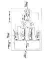
図1は、本発明の実施の形態1に係るスケーラブル復号装置の主要な構成を示すブロック図である。ここでは、拡張レイヤにおいて、コアレイヤよりも広帯域の信号に対し、CELP(Code Excited Linear Prediction)方式をベースとした音声符号化を施す場合を例にとって説明する。(Embodiment 1)
FIG. 1 is a block diagram showing the main configuration of the scalable decoding apparatus according to
本実施の形態に係るスケーラブル復号装置は、コアレイヤ復号部101、アップサンプリング/位相調整部102、狭帯域スペクトル傾き算出部103、拡張レイヤ消失検出部104、拡張レイヤ復号部105、および復号信号加算部106を備え、エンコーダ(図示せず)から送信されたコアレイヤ符号化データおよび拡張レイヤ符号化データを復号する。 The scalable decoding apparatus according to the present embodiment includes a core
本実施の形態に係るスケーラブル復号装置の各部は、以下の動作を行う。 Each unit of the scalable decoding device according to the present embodiment performs the following operation.
コアレイヤ復号部101は、受信したコアレイヤ符号化データを復号し、得られる狭帯域信号であるコアレイヤ復号信号を、コアレイヤ復号信号分析部(図示せず)およびアップサンプリング/位相調整部102に出力する。また、コアレイヤ復号部101は、上記コアレイヤ符号化データに含まれる狭帯域スペクトル情報(狭帯域スペクトルの包絡、エネルギー分布等に関する情報)を狭帯域スペクトル傾き算出部103に出力する。 The core
アップサンプリング/位相調整部102は、コアレイヤ復号信号と拡張レイヤ復号信号と間のサンプリングレート、遅延、および位相のずれを合わせる(補正する)処理を行う。ここでは、コアレイヤ復号信号を拡張レイヤ復号信号に合わせて変換する。ただし、コアレイヤ復号信号および拡張レイヤ復号信号のサンプリングレート、位相等が同一であるならば、ずれを補正する必要はなく、コアレイヤ復号信号を必要に応じて定数倍し出力する。出力信号は復号信号加算部106に出力される。 Upsampling /
狭帯域スペクトル傾き算出部103は、コアレイヤ復号部101から出力される狭帯域スペクトル情報に基づいて、狭帯域スペクトルの周波数方向の減衰直線の傾きを算出し、この算出結果を拡張レイヤ復号部105に出力する。算出された狭帯域スペクトルの減衰直線の傾きは、拡張レイヤの消失データに対する補間データのゲイン(拡張レイヤ補間ゲイン)を制御する際に使用される。 The narrowband spectrum
拡張レイヤ消失検出部104は、拡張レイヤ符号化データに消失があるか否か、すなわち、拡張レイヤ符号化データを復号可能か否かを、符号化データと別個に送信された誤り情報に基づいて検出する。得られた拡張レイヤのフレーム誤り検出結果(拡張レイヤ消失情報)は、拡張レイヤ復号部105に出力される。なお、データ消失の検出方法としては、符号化データに付加されたCRC等の誤り検査符号の検査を行ったり、復号を開始する時間までに符号化データが未着であるか否かを判断したり、パケットロスやパケット未着を検出したりしても良い。また、拡張レイヤ復号部105で受信される符号化データの復号過程において、拡張レイヤ符号化データ内に含まれる誤り検出符号等により重大な誤りを検出した場合に、拡張レイヤ復号部105から拡張レイヤ消失検出部104にその誤り情報が入力されるようにしても良い。 The enhancement layer
拡張レイヤ復号部105は、通常は、受信した拡張レイヤ符号化データを復号し、得られる拡張レイヤ復号信号を復号信号加算部106に出力する。また、拡張レイヤ復号部105は、拡張レイヤ消失検出部104から拡張レイヤ消失情報(フレーム誤り)を通知された場合、すなわち、拡張レイヤのデータ消失時には、復号に必要なパラメータを補間し、補間したパラメータによって補間復号信号を合成し、これを拡張レイヤ復号信号として
復号信号加算部106に出力する。ここで、補間データのゲインは、狭帯域スペクトル傾き算出部103の算出結果に従って制御される。The enhancement
復号信号加算部106は、アップサンプリング/位相調整部102から出力されるコアレイヤ復号信号と、拡張レイヤ復号部105から出力される拡張レイヤ復号信号とを加算し、得られる復号信号を出力する。 Decoded
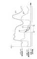
図2および図3は、狭帯域スペクトル傾き算出部103で行われる狭帯域スペクトルの傾きの算出処理を説明するための図である。狭帯域スペクトル傾き算出部103は、線形予測係数の一種であるLSP(Line Spectrum Pair)係数を用いて、以下に示すように、近似的に狭帯域スペクトルの減衰直線の傾きを算出する。 2 and 3 are diagrams for explaining the calculation process of the narrowband spectrum inclination performed by the narrowband spectrum
図2および図3の上段のスペクトルは、狭帯域スペクトルおよび広帯域スペクトルの例を示している。これらの図で、横軸は周波数、縦軸はパワーを表し、コアレイヤとして4kHz以下の狭帯域信号を扱い、拡張レイヤとして8kHz以下の広帯域信号を扱う場合を例にとっている。これらの図において、破線で示される曲線S1、S4が広帯域信号の周波数包絡であり、実線で示される曲線S2、S5が狭帯域信号の周波数包絡である。通常、ナイキスト周波数付近の狭帯域信号は広帯域信号と乖離するが、ナイキスト周波数以下の帯域における周波数パワー分布は近似する。また、実線で示される直線S3、S6が、狭帯域スペクトルの周波数方向の減衰直線である。この減衰直線は、狭帯域スペクトルの減衰具合を示した特性曲線であり、例えば、各サンプル点の回帰直線を求めることによって得られる。 The upper spectrum of FIGS. 2 and 3 shows examples of a narrowband spectrum and a broadband spectrum. In these figures, the horizontal axis represents frequency, and the vertical axis represents power, and a case where a narrowband signal of 4 kHz or less is handled as a core layer and a wideband signal of 8 kHz or less is handled as an extension layer is taken as an example. In these figures, curves S1 and S4 indicated by broken lines are frequency envelopes of a wideband signal, and curves S2 and S5 indicated by solid lines are frequency envelopes of a narrowband signal. Normally, a narrowband signal near the Nyquist frequency deviates from a wideband signal, but the frequency power distribution in a band below the Nyquist frequency is approximated. Further, straight lines S3 and S6 indicated by solid lines are attenuation straight lines in the frequency direction of the narrowband spectrum. This attenuation line is a characteristic curve showing how the narrow band spectrum is attenuated, and can be obtained, for example, by obtaining a regression line of each sample point.
図2の上段のスペクトルは、狭帯域スペクトルの減衰直線の傾き(以下、単に狭帯域スペクトルの傾きと呼ぶ)が緩やかな場合、図3の上段のスペクトルは狭帯域スペクトルの傾きが急峻な場合の例を示している。また、図2および図3の下段の信号は、図2および図3の上段に示された狭帯域スペクトルのLSP係数(分析次数Mを10次とした場合)を示すものである。 The upper spectrum of FIG. 2 is a case where the slope of the attenuation line of the narrowband spectrum (hereinafter simply referred to as the slope of the narrowband spectrum) is gentle, and the upper spectrum of FIG. 3 is a case where the slope of the narrowband spectrum is steep. An example is shown. 2 and FIG. 3 show the LSP coefficients (when the analysis order M is 10th order) of the narrowband spectrum shown in the upper part of FIG. 2 and FIG.
LSP係数の各次数成分は、一般的に、ホルマントのようにスペクトルパワーが集中する箇所においては、隣り合う次数成分どうしが互いに接近して配置され(LSP係数の各次数成分が密集し)、エネルギーが集中していないホルマント間の谷の部分においては、隣り合う次数成分どうしが距離を空けて配置される傾向にある。ここで、LSP係数の隣り合う次数とは、例えば次数iに対し次数i+1のように、連続する次数のことを意味する。 In general, each order component of the LSP coefficient is arranged such that adjacent order components are close to each other (where each order component of the LSP coefficient is dense) at a location where the spectrum power is concentrated, such as a formant. In a valley portion between formants where no concentration is present, adjacent order components tend to be spaced apart from each other. Here, the adjacent orders of the LSP coefficients mean consecutive orders such as the order i + 1 with respect to the order i.
そして、実際、図2および図3の例においても、周波数f0、f1、f2、f3、f4、f5の近傍では、LSP係数の各次数成分が密集し、特に、パワーが最も集中する第1ホルマント付近ではLSP係数の各次数成分間の距離が最も小さくなる傾向が見てとれる。しかも、図2の例では、広帯域信号は高帯域まで存在し、中帯域にもホルマントが見られる。かかる場合、f1やf2付近のLSP係数の各次数成分間の距離も近くなる。一方、図3の例では、広帯域信号においても高帯域信号の強度が弱く、中帯域にもはっきりとしたホルマントが見られない。かかる場合、f4やf5付近のLSP係数の各次数成分間の距離はf1やf2に比べて大きくなる。よって、逆に言えば、LSP係数の各次数成分間の距離が小さい場合には、その箇所により高いエネルギーが存在している可能性が高い。 2 and FIG. 3 also, in the vicinity of the frequencies f0, f1, f2, f3, f4, and f5, the order components of the LSP coefficients are concentrated, and in particular, the first formant in which the power is most concentrated. In the vicinity, it can be seen that the distance between each order component of the LSP coefficient tends to be the smallest. Moreover, in the example of FIG. 2, wideband signals exist up to a high band, and formants are also seen in the middle band. In such a case, the distance between the order components of the LSP coefficients near f1 and f2 is also reduced. On the other hand, in the example of FIG. 3, the intensity of the high-band signal is weak even in the wideband signal, and no clear formant is seen in the middle band. In this case, the distance between the order components of the LSP coefficients near f4 and f5 is larger than f1 and f2. Therefore, conversely, when the distance between each order component of the LSP coefficient is small, there is a high possibility that higher energy exists at that location.
そこで、狭帯域スペクトル傾き算出部103は、LSP係数の上記特徴に基づき、LSP係数の隣り合う次数成分間の距離の2乗の逆数の和を、パワーの大小を判断する際の指標とする。そして、狭帯域全体(狭帯域LSP係数の全次数成分)の疑似パワーと、狭帯
域の高域部(以後、中帯域と呼ぶ)の疑似パワーとを求め、狭帯域全体の疑似パワーに対する中帯域の疑似パワーの比を、狭帯域スペクトルの減衰具合を示すパラメータと捉える。算出される比は、具体的には狭帯域スペクトルの傾きに相当していると考えることができ、この傾きが大きいときは、狭帯域スペクトルが急激に減衰しているということができる。Therefore, the narrowband spectrum
図4は、上記処理を実現する狭帯域スペクトル傾き算出部103内部の主要な構成を示すブロック図である。 FIG. 4 is a block diagram showing a main configuration inside the narrowband spectral
狭帯域スペクトル傾き算出部103は、狭帯域全域パワー算出部121、中帯域パワー算出部122、および除算部123を備え、コアレイヤスペクトル包絡情報を表すM次のLSP係数が入力され、これを用いて狭帯域スペクトルの傾きを算出し、出力する。 The narrowband spectrum
狭帯域全域パワー算出部121は、入力される狭帯域LSP係数Nlsp[t]から、以下の式(1)に基づいて狭帯域全域の疑似パワーNLSPpowALL[t]を算出し、除算部123に出力する。
中帯域パワー算出部122は、狭帯域LSP係数を入力とし、中帯域の疑似パワーを算出し、除算部123に出力する。ここで、中帯域の疑似パワーを算出するために、狭帯域LSP係数の高域部の係数のみを使って疑似パワーを算出する。中帯域パワーNLSPpowMID[t]は、以下の式(2)に基づいて算出する。
除算部123は、以下の式(3)に従って中帯域パワーを狭帯域全域パワーで除算し、狭帯域スペクトルの傾きNtilt[t]を算出する。
このように、狭帯域LSP係数の特徴を使うことにより、狭帯域スペクトルの傾きを算出することができる。 In this way, by using the feature of the narrowband LSP coefficient, the slope of the narrowband spectrum can be calculated.
なお、狭帯域スペクトルの分布によってLSP係数の位置が変わり、これに伴い中帯域の帯域も変わるため、狭帯域スペクトルの傾きの精度が低下することがある。しかし、この精度低下が、拡張レイヤの補間ゲインの減衰速度の聴感的な品質に影響を与えることはほとんどない。 Note that the position of the LSP coefficient changes depending on the distribution of the narrow band spectrum, and the middle band also changes accordingly, so the accuracy of the inclination of the narrow band spectrum may be reduced. However, this decrease in accuracy has little effect on the perceptual quality of the enhancement layer interpolation gain decay rate.
図5は、拡張レイヤ復号部105内部の主要な構成を示すブロック図である。 FIG. 5 is a block diagram showing a main configuration inside enhancement
符号化データ分離部111は、エンコーダ(図示せず)から送信された拡張レイヤ符号化データを入力とし、各符号帳別に符号化データを分離する。分離された符号化データは、拡張レイヤゲイン復号部112、拡張レイヤ適応符号帳復号部113、拡張レイヤ雑音符号帳復号部114、および拡張レイヤLPC復号部115に出力される。 The encoded
拡張レイヤゲイン復号部112は、ピッチゲイン増幅部116およびコードゲイン増幅部117に与えるゲイン量を復号する。具体的には、拡張レイヤゲイン復号部112は、符号化データを復号して得られるゲインを、拡張レイヤ消失情報および狭帯域スペクトル傾き情報に基づいて制御する。得られたゲイン量は、ピッチゲイン増幅部116およびコードゲイン増幅部117にそれぞれ出力される。なお、符号化データが受信できなかった場合、過去の復号情報やコアレイヤ復号信号分析情報を用いて消失データが補間される。 The enhancement layer
拡張レイヤ適応符号帳復号部113には、過去の拡張レイヤ音源信号が拡張レイヤ適応符号帳に格納されており、エンコーダから送信された符号化データによりラグが特定され、このラグに相当するピッチ周期分の信号が切り出される。出力信号は、ピッチゲイン増幅部116に出力される。なお、符号化データが受信できなかった場合、過去のラグやコアレイヤの情報を用いて消失データが補間される。 In the enhancement layer adaptive
拡張レイヤ雑音符号帳復号部114は、上記の拡張レイヤ適応符号帳によっては表現しきれない、すなわち周期成分には該当しない雑音的な信号成分を表現するための信号を生成する。この信号は、近年のコーデックにおいては、代数的に表現されることが多い。出力信号は、コードゲイン増幅部117に出力される。なお、符号化データが受信できなかった場合、拡張レイヤの過去の復号情報やコアレイヤの復号情報、もしくは乱数値等を用いて消失データが補間される。 The enhancement layer noise
拡張レイヤLPC復号部115は、エンコーダから送信された符号化データを復号し、得られる線形予測係数を合成フィルタのフィルタ係数用に拡張レイヤ合成フィルタ119に出力する。なお、符号化データが受信できなかった場合、過去に受信した符号化データを用いて消失データの補間を行ったり、コアレイヤのLPC情報をさらに用いて消失データの復号を行う。この際、コアレイヤと拡張レイヤとで線形予測の分析次数が異なる場合、コアレイヤのLPCを次数拡張してから補間に使用する。 The enhancement layer
ピッチゲイン増幅部116は、拡張レイヤ適応符号帳復号部113の出力信号に対し、拡張レイヤゲイン復号部112から出力されるピッチゲインを乗じて増幅し、音源加算部118に出力する。 Pitch
コードゲイン増幅部117は、拡張レイヤ雑音符号帳復号部114の出力信号に対し、拡張レイヤゲイン復号部112から出力されるコードゲインを乗じて増幅し、音源加算部118に出力する。 The code
音源加算部118は、ピッチゲイン増幅部116およびコードゲイン増幅部117から出力される信号を加算することにより拡張レイヤ音源信号を生成し、これを拡張レイヤ合
成フィルタ119に出力する。The sound
拡張レイヤ合成フィルタ119は、拡張レイヤLPC復号部115から出力されたLPC係数によって合成フィルタを形成し、音源加算部118から出力された拡張レイヤ音源信号を入力として駆動することにより、拡張レイヤ復号信号を得る。この拡張レイヤ復号信号は、復号信号加算部106に出力される。なお、この拡張レイヤ復号信号に対し、さらにポストフィルタリング処理を行っても良い。 The enhancement
図6は、拡張レイヤゲイン復号部112内部の主要な構成を示すブロック図である。 FIG. 6 is a block diagram showing a main configuration inside enhancement layer
拡張レイヤゲイン復号部112は、拡張レイヤゲイン符号帳復号部131、ゲイン選択部132、ゲイン減衰部134、過去ゲイン蓄積部135、およびゲイン減衰率算出部133を備え、拡張レイヤのデータ消失時に、過去の拡張レイヤのゲイン値と、狭帯域スペクトルの傾きの情報とによって、拡張レイヤの補間ゲインの制御を行う。具体的には、符号化データ、拡張レイヤ消失情報、および狭帯域スペクトルの傾きが入力され、ピッチゲインGep[t]およびコードゲインGec[t]の2種のゲインを出力する。 The enhancement layer
拡張レイヤゲイン符号帳復号部131は、符号化データを受け取ると、これを復号して、得られる復号ゲインDGep[t]、DGec[t]を、ゲイン選択部132に出力する。 Upon receiving the encoded data, the enhancement layer gain
ゲイン選択部132には、拡張レイヤ消失情報と、復号ゲイン(DGep[t]、DGec[t])と、過去ゲイン蓄積部135から出力される過去ゲインとが入力される。ゲイン選択部132は、拡張レイヤ消失情報によって、復号ゲインを用いるか、または過去ゲインを用いるかを選択し、選択したゲインをゲイン減衰部134に出力する。具体的には、符号化データを受信しているときには復号ゲインを出力し、データ消失時は過去ゲインを出力する。 The
ゲイン減衰率算出部133は、拡張レイヤ消失情報と狭帯域スペクトルの傾き情報とから、ゲイン減衰率を算出し、ゲイン減衰部134に出力する。 The gain attenuation
ゲイン減衰部134は、ゲイン減衰率算出部133で算出されたゲイン減衰率を、ゲイン選択部132からの出力に乗じることによって、減衰後のゲインを求め、これを出力する。 The
過去ゲイン蓄積部135は、ゲイン減衰部134によって減衰されたゲインを過去ゲインとして蓄積しておく。蓄積された過去ゲインは、ゲイン選択部132に出力される。 The past
次に、本実施の形態に係るゲイン制御方法について、数式を交えて具体的に説明する。 Next, the gain control method according to the present embodiment will be specifically described using mathematical expressions.
ゲイン減衰率算出部133は、狭帯域スペクトルの傾きが緩やかな場合はゲイン減衰率を弱めに設定し、ゲインが緩やかに減衰するようにする。また、狭帯域スペクトルの傾きが大きい場合はゲイン減衰率を強めに設定し、ゲインが大きく減衰するようにする。ゲイン減衰率は、以下の式(4)を用いて算出される。
ここで、Gatt[t]はゲイン減衰率、βは傾きを補正する係数で0.0より大きい正数、αは減衰率の幅を制御する係数で0.0<α<1.0の値をとる。ピッチゲインとコードゲインとで各係数を変更しても良い。 Here, Gatt [t] is a gain attenuation rate, β is a coefficient for correcting the slope, and is a positive number larger than 0.0, α is a coefficient for controlling the width of the attenuation rate, and a value of 0.0 <α <1.0. Take. Each coefficient may be changed between the pitch gain and the code gain.
ゲイン減衰部134は、以下の式(5)、(6)に従って、ピッチゲインGep[t]およびコードゲインGec[t]を減衰させる。
次いで、本実施の形態に係るスケーラブル復号装置によって復号された拡張レイヤの音源信号について、具体例を交えながら説明する。 Next, enhancement layer excitation signals decoded by the scalable decoding apparatus according to the present embodiment will be described with specific examples.
図7は、音声信号のスペクトルパワーの偏りの一例を示す図である。横軸が時間、縦軸が周波数を表す。斜線で示した帯域にパワーが集中していることを表している。 FIG. 7 is a diagram illustrating an example of the spectral power bias of an audio signal. The horizontal axis represents time, and the vertical axis represents frequency. This indicates that power is concentrated in the band indicated by the diagonal lines.
まず、話頭で子音成分の大部分が約4kHz以上の高域に分布する。その後、およそT1以降は母音成分が続き、その母音成分は高域に高調波成分も伴って、T3付近までは高調波が存在する。一方、T3からT4の間では、約4kHz以下の低域のうち、基本周波数に近い約2kHz以下の高調波成分があまり減衰しないにも関わらず、中帯域(3kHz付近)以上の高調波が急激に減衰し、高調波が存在しなくなる。この図に示した状況下では、拡張レイヤ音源パワーも急激に減少することになる。 First, most of the consonant components are distributed in a high frequency range of about 4 kHz or more at the beginning of the talk. Thereafter, a vowel component continues after about T1, the vowel component is accompanied by a harmonic component in a high region, and a harmonic exists up to the vicinity of T3. On the other hand, between T3 and T4, harmonics in the middle band (near 3 kHz) suddenly abruptly fall out of the low frequency range of about 4 kHz or less, although the harmonic component of about 2 kHz or less, which is close to the fundamental frequency, is not significantly attenuated. Attenuates and no harmonics exist. Under the situation shown in this figure, the enhancement layer sound source power also decreases rapidly.
図8および図9は、図7のスペクトルパワー分布を示す音声信号に対して音源補間処理をした際の、復号された拡張レイヤの音源信号のパワーの推移を示す図である。横軸は時間、縦軸はパワーを表し、拡張レイヤの音源信号のパワーS12と共に、コアレイヤ復号信号のパワーS11も示している。なお、S12、S11は、正常受信時のパワーを示している。 8 and 9 are diagrams showing the transition of the power of the decoded enhancement layer sound source signal when the sound source interpolation processing is performed on the sound signal having the spectral power distribution of FIG. The horizontal axis represents time, and the vertical axis represents power. The power S11 of the core layer decoded signal is shown together with the power S12 of the enhancement layer excitation signal. S12 and S11 indicate power at the time of normal reception.
また、これらの図において、拡張レイヤ消失情報(受信/非受信情報)も併せて示している。図8の例では、時刻T1まで正常受信状態、T1からT2までデータ消失によって受信不可状態(非受信状態)、T2以降が正常受信状態である。また、図9の例では、T3まで正常受信状態、T3からT4まで非受信状態、T4以降が正常受信状態である。 In these drawings, enhancement layer loss information (reception / non-reception information) is also shown. In the example of FIG. 8, the normal reception state is until time T1, the reception is not possible (non-reception state) due to data loss from T1 to T2, and the normal reception state is after T2. In the example of FIG. 9, the normal reception state is from T3, the non-reception state is from T3 to T4, and the normal reception state is from T4.
図8の例は、本実施の形態に係るスケーラブル復号装置によって、ゲインの減衰速度が緩められる場合を示している(L2が該当)。この例では、T1に拡張レイヤを消失し、拡張レイヤでは音源の補間を始める。例えば、ゲインを定率で減衰させるような方法では、弱い減衰による帯域感の維持と強い減衰による異音の発生の回避という2つ相反する要求に対して、バランスをとれるような1つの値が設定される(L1が該当)。 The example of FIG. 8 illustrates a case where the gain decay rate is relaxed by the scalable decoding device according to the present embodiment (L2 is applicable). In this example, the enhancement layer disappears at T1, and sound source interpolation is started in the enhancement layer. For example, in a method in which the gain is attenuated at a constant rate, a single value is set to balance the two conflicting demands of maintaining a sense of bandwidth due to weak attenuation and avoiding the generation of abnormal noise due to strong attenuation. (L1 is applicable).
一方、図8の例では、高調波が高域まで存在し、コアレイヤの中帯域にも高調波が存在するため、ホルマントが存在する可能性が非常に高い。かかる場合、狭帯域スペクトルの
傾きは緩やかとなるため、本実施の形態に係るスケーラブル復号装置は、拡張レイヤゲインの減衰係数を弱めに設定する(L2)。これにより、高域の音源は過去や狭帯域信号との相関性が強くなるため、外挿し易くなり、自然な補間が可能となる。On the other hand, in the example of FIG. 8, since harmonics exist up to a high frequency, and harmonics exist in the middle band of the core layer, the possibility that formants exist is very high. In such a case, since the slope of the narrowband spectrum becomes gentle, the scalable decoding device according to the present embodiment sets the attenuation coefficient of the enhancement layer gain to be weak (L2). As a result, the high-frequency sound source has a strong correlation with the past and narrow band signals, so that extrapolation is easy and natural interpolation is possible.
図9の例は、本実施の形態に係るスケーラブル復号装置によって、ゲインの減衰速度が強められた場合を示している(L4が該当)。この例では、T3に拡張レイヤを消失し、拡張レイヤでは音源の補間を始める。例えば、ゲインを定率で減衰させるような方法では、図8の例と同様に、本来の拡張レイヤの音源パワーレベル(S14)を上回るゲインにしか減衰しきれないため(L3)、本来であれば信号が無い帯域の信号をも過強調することになり、異音発生の原因となる。一方、本実施の形態に係るスケーラブル復号装置は、拡張レイヤゲインの減衰係数を強めに設定する(L4)。これにより、本来の拡張レイヤの音源パワーレベル(S14)を下回るゲインに減衰することができ、より自然な補間が可能となる。 The example of FIG. 9 illustrates a case where the gain decay rate is increased by the scalable decoding device according to the present embodiment (L4 is applicable). In this example, the enhancement layer disappears at T3, and sound source interpolation is started in the enhancement layer. For example, in the method of attenuating the gain at a constant rate, as in the example of FIG. 8, since it can only be attenuated to a gain that exceeds the sound source power level (S14) of the original enhancement layer (L3), Even a signal in a band where there is no signal is overemphasized, causing abnormal noise. On the other hand, the scalable decoding device according to the present embodiment sets the attenuation coefficient of the enhancement layer gain to be stronger (L4). As a result, the gain can be attenuated to a value lower than the sound source power level (S14) of the original enhancement layer, and more natural interpolation is possible.
図9の例(T4付近)では、中帯域以上の高域側で高調波が存在せず、信号パワーが低域に大きく偏っている。かかる場合、本実施の形態に係るスケーラブル復号装置によれば、狭帯域スペクトルの傾きが急になっているため、拡張レイヤ補間ゲインの減衰速度を強めに設定する。そのため、本来信号が存在しない高域に対して過強調することを避けることができるため、異音の発生を回避することができる。 In the example of FIG. 9 (near T4), there is no harmonic on the high band side above the middle band, and the signal power is greatly biased to the low band. In such a case, according to the scalable decoding device according to the present embodiment, since the slope of the narrowband spectrum is steep, the attenuation rate of the enhancement layer interpolation gain is set stronger. For this reason, it is possible to avoid overemphasis on a high frequency range where no signal originally exists, and thus it is possible to avoid the generation of abnormal noise.
このように、本実施の形態によれば、拡張レイヤの符号化データ消失時に、狭帯域音声スペクトルの傾きを用いて拡張レイヤの補間データのゲインを適切に推定することにより、自然な補間音声を生成する。すなわち、拡張レイヤ消失時に、狭帯域スペクトル傾き算出部103で得られる狭帯域スペクトル傾きの結果に基づき、その傾きに応じて拡張レイヤの補間ゲインの減衰速度を制御する。具体的には、狭帯域スペクトルが高域側に向かって緩やかに減少している場合、拡張レイヤ補間ゲインの減衰を弱めることで帯域感を維持する。一方、狭帯域スペクトルが高域側に向かって急速に減少している場合には、拡張レイヤ補間ゲインの減衰を強めることでゲインの過大推定を防ぎ、異音の発生を防止する。 As described above, according to the present embodiment, when the encoded data of the enhancement layer is lost, natural interpolation speech is obtained by appropriately estimating the gain of the interpolation data of the enhancement layer using the slope of the narrowband speech spectrum. Generate. That is, when the enhancement layer disappears, based on the result of the narrowband spectrum tilt obtained by the narrowband spectrum
より詳細には、下位レイヤである狭帯域音声の周波数情報(包絡情報)から、狭帯域信号のスペクトルの傾きを算出し、この傾きが大きい場合、すなわち、高域側に対してパワー減少が大きい場合には、拡張レイヤの補間ゲインを抑圧し、上記傾きが小さい場合は拡張レイヤの補間ゲインの減衰を緩くする。 More specifically, the slope of the spectrum of the narrowband signal is calculated from the frequency information (envelope information) of the narrowband audio that is the lower layer, and when this slope is large, that is, the power reduction is large relative to the high frequency side. In this case, the interpolation gain of the enhancement layer is suppressed, and when the slope is small, the attenuation of the enhancement gain of the enhancement layer is reduced.
一般に狭帯域の信号から、より高域の信号を正確に推測にするのは困難であるため、拡張レイヤの消失が長くなるにつれて補間された広帯域信号は不正確になり音質劣化の原因となり得る。そのため、拡張レイヤ消失期間が長くなるにつれ拡張レイヤ補間信号を減衰し、帯域感が無いながらも(正常に受信しているため)正確な復号信号である狭帯域信号へと切替えていくことが望ましいと考えられる。そこで、本実施の形態では、上記を実現するための拡張レイヤのゲイン推定に、以下に示す音声、特に母音等の有声音の周波数的特徴を用いる。 In general, it is difficult to accurately estimate a higher-frequency signal from a narrow-band signal, so that the interpolated wide-band signal becomes inaccurate as the loss of the enhancement layer becomes longer, which may cause deterioration in sound quality. Therefore, it is desirable to attenuate the enhancement layer interpolated signal as the enhancement layer disappearance period becomes longer, and to switch to a narrowband signal that is an accurate decoded signal even though there is no sense of bandwidth (because it is normally received). it is conceivable that. Therefore, in the present embodiment, the frequency characteristics of voice, particularly voiced sounds such as vowels, shown below, are used for gain estimation of the enhancement layer for realizing the above.
すなわち、第1の特徴として、コアレイヤの帯域(狭帯域)のスペクトル分布(具体的には傾き)と、拡張レイヤまで含む帯域(広帯域)のスペクトル分布には相関性がある。換言すると、傾きが高域に向かって緩やかに減少している場合は、基本周波数の高調波が高域にも引き続き存在する可能性があり、従って高域側の信号にもパワーがあると考えられる。一方、傾きが高域に向かって急に減少している場合は、高調波が高域に存在する可能性が低く、従って高域側の信号にはパワーが小さいと考えられる。 That is, as a first feature, there is a correlation between the spectrum distribution (specifically slope) of the band (narrow band) of the core layer and the spectrum distribution (wideband) including the enhancement layer. In other words, if the slope is gradually decreasing toward the high range, harmonics of the fundamental frequency may continue to exist in the high range, and therefore the high frequency side signal is considered to have power. It is done. On the other hand, when the slope suddenly decreases toward the high band, it is unlikely that the higher harmonics are present in the high band, and therefore, the signal on the high band side has a low power.
第2の特徴として、コアレイヤ帯域の傾きが緩やかな信号は、過去の信号との相関性が
ある。母音等の有声音である場合は、高調波が高域まで存在するため傾きが緩やかになる。高調波は狭帯域の信号から推測しやすく、かつ低域側の信号と同様に緩やかに変化すると考えられるため過去の信号との相関性も高い。一方、コアレイヤ帯域の傾きが急に減少するような場合は、高域側に高調波が存在する可能性が低く高域側に信号がほとんどなかったり、過去の信号とは相関性の低い信号が存在すると考えられる。As a second feature, a signal having a gentle slope of the core layer band has a correlation with a past signal. In the case of a voiced sound such as a vowel, the inclination is gentle because harmonics exist up to a high frequency. Harmonics are easy to guess from narrow-band signals, and are considered to change slowly like low-frequency signals, and therefore have high correlation with past signals. On the other hand, when the slope of the core layer band suddenly decreases, there is little possibility that harmonics exist on the high frequency side, and there is almost no signal on the high frequency side, or there is a signal that has a low correlation with the past signal. Presumed to exist.
以上の音声の特徴により、コアレイヤ帯域の傾きが緩やかな場合は、高帯域側の信号もパワー変動が緩やかであり過去の信号との相関性も高いため、拡張レイヤゲインの減衰を弱めに設定することで、自然な補償音声を得ることができる。一方、コアレイヤ帯域の傾きが急である場合は、高域側にパワーがもともと存在しない、もしくは過去とは相関性が低い信号が存在すると考えられ、拡張レイヤゲインの減衰を強めに設定することで、異音の発生を防ぐことができる。 Due to the above audio characteristics, when the slope of the core layer band is gradual, the power fluctuation of the high band side signal is also gradual and the correlation with the past signal is high. Thus, natural compensation sound can be obtained. On the other hand, when the slope of the core layer band is steep, it is considered that there is no signal on the high frequency side, or there is a signal that has a low correlation with the past, and by setting the attenuation of the enhancement layer gain stronger , Can prevent the generation of abnormal noise.
すなわち、本実施の形態に係るスケーラブル復号装置により、拡張レイヤゲインを適切に推定することによって、拡張レイヤ復号信号の帯域感を維持しつつ異音の発生を抑えることができる。よって、拡張レイヤ消失に伴う異音感を抑制することができ、かつ帯域感を維持することができる。 That is, by appropriately estimating the enhancement layer gain by the scalable decoding device according to the present embodiment, it is possible to suppress the occurrence of abnormal noise while maintaining the sense of bandwidth of the enhancement layer decoded signal. Therefore, it is possible to suppress the sense of noise accompanying the disappearance of the enhancement layer and to maintain a sense of bandwidth.
なお、本実施の形態では、フレーム消失時に、狭帯域スペクトルの傾きに応じて拡張レイヤゲインの減衰速度を制御する場合を例にとって説明したが、拡張レイヤゲインをコアレイヤ復号信号のパワーもしくはコアレイヤのゲインに対する相対値で表し、この相対値を狭帯域スペクトル傾きに応じて制御しても良い。 In this embodiment, the case where the attenuation rate of the enhancement layer gain is controlled according to the inclination of the narrowband spectrum at the time of frame disappearance has been described as an example. However, the enhancement layer gain is the power of the core layer decoded signal or the gain of the core layer. The relative value may be controlled in accordance with the narrow band spectrum inclination.
また、本実施の形態では、補間の処理単位を、音声符号化の処理単位(フレーム)とした場合、すなわち各フレームごとに補間を行う場合を例にとって説明したが、フレームよりも短い、例えばサブフレーム等の一定時間を、補間の処理単位としても良い。 Further, in the present embodiment, the case where the interpolation processing unit is the speech encoding processing unit (frame), that is, the case where interpolation is performed for each frame has been described as an example. A certain time such as a frame may be used as a unit of interpolation processing.
さらに、本実施の形態では、狭帯域スペクトルの傾き算出をする際に、狭帯域信号の符号化データを復号して得られるスペクトル情報を用いる場合を例にとって説明したが、狭帯域信号のスペクトル情報の代わりに、コアレイヤで得られる復号信号を用いても良い。すなわち、このコアレイヤ復号信号をFFT(高速フーリエ変換)により周波数変換し、その周波数分布に基づいて、狭帯域スペクトルの傾きを算出することが可能であるし、線形予測係数もしくは同等の周波数包絡情報を伝送している場合には、これらのパラメータから周波数包絡情報を得、これを用いて狭帯域スペクトルの傾きを算出しても良い。 Furthermore, in the present embodiment, the case of using spectral information obtained by decoding encoded data of a narrowband signal when calculating the slope of the narrowband spectrum has been described as an example. Instead of this, a decoded signal obtained in the core layer may be used. That is, it is possible to frequency-convert this core layer decoded signal by FFT (Fast Fourier Transform), calculate the slope of the narrowband spectrum based on the frequency distribution, and to calculate linear prediction coefficients or equivalent frequency envelope information. In the case of transmission, frequency envelope information may be obtained from these parameters, and the slope of the narrowband spectrum may be calculated using this information.
以上、本発明の実施の形態について説明した。 The embodiment of the present invention has been described above.
本発明に係るスケーラブル復号装置および消失データ補間方法は、上記実施の形態に限定されず、種々変更して実施することが可能である。 The scalable decoding device and erasure data interpolation method according to the present invention are not limited to the above-described embodiments, and can be implemented with various modifications.
本発明に係るスケーラブル復号装置は、移動体通信システムにおける通信端末装置および基地局装置に搭載することが可能であり、これにより上記と同様の作用効果を有する通信端末装置、基地局装置、および移動体通信システムを提供することができる。 The scalable decoding device according to the present invention can be mounted on a communication terminal device and a base station device in a mobile communication system, and thereby has a function and effect similar to the above, a communication terminal device, a base station device, and a mobile A body communication system can be provided.
なお、ここでは、本発明をハードウェアで構成する場合を例にとって説明したが、本発明をソフトウェアで実現することも可能である。例えば、本発明に係る消失データ補間方法のアルゴリズムをプログラミング言語によって記述し、このプログラムをメモリに記憶しておいて情報処理手段によって実行させることにより、本発明に係るスケーラブル復号装置と同様の機能を実現することができる。 Here, the case where the present invention is configured by hardware has been described as an example, but the present invention can also be realized by software. For example, by describing the algorithm of the lost data interpolation method according to the present invention in a programming language, storing this program in a memory and executing it by the information processing means, the same function as the scalable decoding device according to the present invention is achieved. Can be realized.
また、上記各実施の形態の説明に用いた各機能ブロックは、典型的には集積回路であるLSIとして実現される。これらは個別に1チップ化されても良いし、一部または全てを含むように1チップ化されても良い。 Each functional block used in the description of each of the above embodiments is typically realized as an LSI which is an integrated circuit. These may be individually made into one chip, or may be made into one chip so as to include a part or all of them.
また、ここではLSIとしたが、集積度の違いによって、IC、システムLSI、スーパーLSI、ウルトラLSI等と呼称されることもある。 Although referred to as LSI here, it may be called IC, system LSI, super LSI, ultra LSI, or the like depending on the degree of integration.
また、集積回路化の手法はLSIに限るものではなく、専用回路または汎用プロセッサで実現しても良い。LSI製造後に、プログラム化することが可能なFPGA(Field Programmable Gate Array)や、LSI内部の回路セルの接続もしくは設定を再構成可能なリコンフィギュラブル・プロセッサを利用しても良い。 Further, the method of circuit integration is not limited to LSI's, and implementation using dedicated circuitry or general purpose processors is also possible. An FPGA (Field Programmable Gate Array) that can be programmed after manufacturing the LSI or a reconfigurable processor that can reconfigure the connection or setting of circuit cells inside the LSI may be used.
さらに、半導体技術の進歩または派生する別技術により、LSIに置き換わる集積回路化の技術が登場すれば、当然、その技術を用いて機能ブロックの集積化を行っても良い。バイオ技術の適応等が可能性としてあり得る。 Further, if integrated circuit technology comes out to replace LSI's as a result of the advancement of semiconductor technology or a derivative other technology, it is naturally also possible to carry out function block integration using this technology. There is a possibility of adaptation of biotechnology.
本明細書は、2005年6月29日出願の特願2005−189532に基づく。この内容はすべてここに含めておく。 This specification is based on Japanese Patent Application No. 2005-189532 of an application on June 29, 2005. All this content is included here.
本発明に係るスケーラブル復号装置および消失データ補間方法は、移動体通信システムにおける通信端末装置、基地局装置等の用途に適用することができる。 The scalable decoding device and erasure data interpolation method according to the present invention can be applied to applications such as a communication terminal device and a base station device in a mobile communication system.
Claims (9)
Translated fromJapanese広帯域信号の符号化データを復号する一方、当該符号化データが存在しない場合、代わりの補間データを生成する広帯域復号手段と、
前記狭帯域信号の符号化データに基づいて、前記狭帯域信号のスペクトルの周波数方向の減衰具合を算出する算出手段と、
前記補間データが生成された場合、前記減衰具合に応じて前記補間データのゲインを制御する制御手段と、
を具備するスケーラブル復号装置。Narrowband decoding means for decoding encoded data of a narrowband signal;
Wideband decoding means for decoding the wideband signal encoded data, and generating alternative interpolation data if the encoded data does not exist;
Based on the encoded data of the narrowband signal, calculation means for calculating the degree of attenuation in the frequency direction of the spectrum of the narrowband signal;
When the interpolation data is generated, control means for controlling the gain of the interpolation data according to the attenuation level;
A scalable decoding device comprising:
前記減衰具合に応じて前記ゲインの減衰速度を制御する、
請求項1記載のスケーラブル復号装置。The control means includes
Controlling the rate of attenuation of the gain according to the degree of attenuation;
The scalable decoding device according to claim 1.
請求項1記載のスケーラブル復号装置。The degree of attenuation is the slope of the attenuation line of the spectrum of the narrowband signal.
The scalable decoding device according to claim 1.
前記傾きが急なほど前記ゲインの減衰速度を早くする、
請求項3記載のスケーラブル復号装置。The control means includes
The faster the slope, the faster the gain decay rate,
The scalable decoding device according to claim 3.
請求項1記載のスケーラブル復号装置。The encoded data of the narrowband signal includes encoded data of spectrum information of the narrowband signal.
The scalable decoding device according to claim 1.
前記狭帯域信号の符号化データを復号して前記狭帯域信号のスペクトルを得、当該スペクトルから前記減衰具合を算出する、
請求項1記載のスケーラブル復号装置。The calculating means includes
Decoding the encoded data of the narrowband signal to obtain a spectrum of the narrowband signal, and calculating the attenuation degree from the spectrum,
The scalable decoding device according to claim 1.
広帯域信号の符号化データを復号するステップと、
前記広帯域信号の符号化データが存在しない場合、代わりの補間データを生成するステップと、
前記狭帯域信号の符号化データに基づいて、前記狭帯域信号のスペクトルの周波数方向の減衰具合を算出するステップと、
前記補間データが生成された場合、前記減衰具合に応じて前記補間データのゲインを制御するステップと、
を具備する消失データ補間方法。Decoding the encoded data of the narrowband signal;
Decoding the encoded data of the wideband signal;
If there is no encoded data of the wideband signal, generating alternative interpolation data;
Calculating the degree of attenuation in the frequency direction of the spectrum of the narrowband signal based on the encoded data of the narrowband signal;
When the interpolation data is generated , controlling the gain of the interpolation data according to the attenuation level;
An erasure data interpolation method comprising:
Priority Applications (1)
| Application Number | Priority Date | Filing Date | Title |
|---|---|---|---|
| JP2007523948AJP5100380B2 (en) | 2005-06-29 | 2006-06-27 | Scalable decoding apparatus and lost data interpolation method |
Applications Claiming Priority (4)
| Application Number | Priority Date | Filing Date | Title |
|---|---|---|---|
| JP2005189532 | 2005-06-29 | ||
| JP2005189532 | 2005-06-29 | ||
| PCT/JP2006/312779WO2007000988A1 (en) | 2005-06-29 | 2006-06-27 | Scalable decoder and disappeared data interpolating method |
| JP2007523948AJP5100380B2 (en) | 2005-06-29 | 2006-06-27 | Scalable decoding apparatus and lost data interpolation method |
Publications (2)
| Publication Number | Publication Date |
|---|---|
| JPWO2007000988A1 JPWO2007000988A1 (en) | 2009-01-22 |
| JP5100380B2true JP5100380B2 (en) | 2012-12-19 |
Family
ID=37595238
Family Applications (1)
| Application Number | Title | Priority Date | Filing Date |
|---|---|---|---|
| JP2007523948AExpired - Fee RelatedJP5100380B2 (en) | 2005-06-29 | 2006-06-27 | Scalable decoding apparatus and lost data interpolation method |
Country Status (6)
| Country | Link |
|---|---|
| US (1) | US8150684B2 (en) |
| EP (1) | EP1898397B1 (en) |
| JP (1) | JP5100380B2 (en) |
| CN (1) | CN101213590B (en) |
| DE (1) | DE602006009931D1 (en) |
| WO (1) | WO2007000988A1 (en) |
Families Citing this family (28)
| Publication number | Priority date | Publication date | Assignee | Title |
|---|---|---|---|---|
| FR2897977A1 (en)* | 2006-02-28 | 2007-08-31 | France Telecom | Coded digital audio signal decoder`s e.g. G.729 decoder, adaptive excitation gain limiting method for e.g. voice over Internet protocol network, involves applying limitation to excitation gain if excitation gain is greater than given value |
| KR100906766B1 (en)* | 2007-06-18 | 2009-07-09 | 한국전자통신연구원 | Voice data transmission and reception apparatus and method for voice data prediction in key resynchronization section |
| WO2009008220A1 (en)* | 2007-07-09 | 2009-01-15 | Nec Corporation | Sound packet receiving device, sound packet receiving method and program |
| CN100524462C (en)* | 2007-09-15 | 2009-08-05 | 华为技术有限公司 | Method and apparatus for concealing frame error of high belt signal |
| BRPI0818927A2 (en) | 2007-11-02 | 2015-06-16 | Huawei Tech Co Ltd | Method and apparatus for audio decoding |
| CN101308660B (en)* | 2008-07-07 | 2011-07-20 | 浙江大学 | Decoding terminal error recovery method of audio compression stream |
| WO2010031003A1 (en)* | 2008-09-15 | 2010-03-18 | Huawei Technologies Co., Ltd. | Adding second enhancement layer to celp based core layer |
| CN101964189B (en)* | 2010-04-28 | 2012-08-08 | 华为技术有限公司 | Audio signal switching method and device |
| US9082412B2 (en) | 2010-06-11 | 2015-07-14 | Panasonic Intellectual Property Corporation Of America | Decoder, encoder, and methods thereof |
| US9047875B2 (en) | 2010-07-19 | 2015-06-02 | Futurewei Technologies, Inc. | Spectrum flatness control for bandwidth extension |
| KR101747917B1 (en) | 2010-10-18 | 2017-06-15 | 삼성전자주식회사 | Apparatus and method for determining weighting function having low complexity for lpc coefficients quantization |
| FI4239635T3 (en) | 2010-11-22 | 2025-07-29 | Ntt Docomo Inc | AUDIO CODING DEVICE AND METHOD |
| EP4239635B1 (en) | 2010-11-22 | 2025-06-25 | Ntt Docomo, Inc. | Audio encoding device and method |
| JP5724338B2 (en)* | 2010-12-03 | 2015-05-27 | ソニー株式会社 | Encoding device, encoding method, decoding device, decoding method, and program |
| US9536534B2 (en) | 2011-04-20 | 2017-01-03 | Panasonic Intellectual Property Corporation Of America | Speech/audio encoding apparatus, speech/audio decoding apparatus, and methods thereof |
| CN103295578B (en) | 2012-03-01 | 2016-05-18 | 华为技术有限公司 | A voice and audio signal processing method and device |
| US10034013B2 (en)* | 2012-12-05 | 2018-07-24 | Intel Corporation | Recovering motion vectors from lost spatial scalability layers |
| TWI521946B (en) | 2012-12-21 | 2016-02-11 | 杜比實驗室特許公司 | High precision up-sampling in scalable coding of high bit-depth video |
| US9711156B2 (en)* | 2013-02-08 | 2017-07-18 | Qualcomm Incorporated | Systems and methods of performing filtering for gain determination |
| MX358362B (en)* | 2013-06-21 | 2018-08-15 | Fraunhofer Ges Forschung | Audio decoder having a bandwidth extension module with an energy adjusting module. |
| CN107818789B (en)* | 2013-07-16 | 2020-11-17 | 华为技术有限公司 | Decoding method and decoding device |
| CN104301064B (en) | 2013-07-16 | 2018-05-04 | 华为技术有限公司 | Method and decoder for handling lost frames |
| CN105761723B (en)* | 2013-09-26 | 2019-01-15 | 华为技术有限公司 | A kind of high-frequency excitation signal prediction technique and device |
| EP3089161B1 (en)* | 2013-12-27 | 2019-10-23 | Sony Corporation | Decoding device, method, and program |
| CN106683681B (en)* | 2014-06-25 | 2020-09-25 | 华为技术有限公司 | Method and apparatus for handling lost frames |
| KR102298767B1 (en)* | 2014-11-17 | 2021-09-06 | 삼성전자주식회사 | Voice recognition system, server, display apparatus and control methods thereof |
| US10825467B2 (en)* | 2017-04-21 | 2020-11-03 | Qualcomm Incorporated | Non-harmonic speech detection and bandwidth extension in a multi-source environment |
| CN113792185B (en)* | 2021-07-30 | 2023-07-14 | 中国电子产品可靠性与环境试验研究所((工业和信息化部电子第五研究所)(中国赛宝实验室)) | Estimating missing signal method, device, computer equipment and storage medium |
Citations (2)
| Publication number | Priority date | Publication date | Assignee | Title |
|---|---|---|---|---|
| JPH06125361A (en)* | 1992-10-09 | 1994-05-06 | Nippon Telegr & Teleph Corp <Ntt> | Voice packet communication system |
| JP2003241799A (en)* | 2002-02-15 | 2003-08-29 | Nippon Telegr & Teleph Corp <Ntt> | Acoustic encoding method, decoding method, encoding device, decoding device, encoding program, decoding program |
Family Cites Families (16)
| Publication number | Priority date | Publication date | Assignee | Title |
|---|---|---|---|---|
| US5894473A (en)* | 1996-02-29 | 1999-04-13 | Ericsson Inc. | Multiple access communications system and method using code and time division |
| EP0883107B9 (en) | 1996-11-07 | 2005-01-26 | Matsushita Electric Industrial Co., Ltd | Sound source vector generator, voice encoder, and voice decoder |
| CN100349208C (en) | 1997-10-22 | 2007-11-14 | 松下电器产业株式会社 | Diffusion vector generation method and diffusion vector generation device |
| US6252915B1 (en)* | 1998-09-09 | 2001-06-26 | Qualcomm Incorporated | System and method for gaining control of individual narrowband channels using a wideband power measurement |
| JP2000352999A (en) | 1999-06-11 | 2000-12-19 | Nec Corp | Audio switching device |
| US7315815B1 (en)* | 1999-09-22 | 2008-01-01 | Microsoft Corporation | LPC-harmonic vocoder with superframe structure |
| US6445696B1 (en)* | 2000-02-25 | 2002-09-03 | Network Equipment Technologies, Inc. | Efficient variable rate coding of voice over asynchronous transfer mode |
| EP1199709A1 (en) | 2000-10-20 | 2002-04-24 | Telefonaktiebolaget Lm Ericsson | Error Concealment in relation to decoding of encoded acoustic signals |
| CN1327409C (en) | 2001-01-19 | 2007-07-18 | 皇家菲利浦电子有限公司 | Wideband signal transmission system |
| ES2244557T3 (en)* | 2001-01-31 | 2005-12-16 | Teldix Gmbh | MODULAR AND SCALABLE SWITCHING CENTER AND METHOD FOR THE DISTRIBUTION OF DATA FRAMES IN A FAST ETHERNET NETWORK. |
| US7617096B2 (en)* | 2001-08-16 | 2009-11-10 | Broadcom Corporation | Robust quantization and inverse quantization using illegal space |
| US7610198B2 (en)* | 2001-08-16 | 2009-10-27 | Broadcom Corporation | Robust quantization with efficient WMSE search of a sign-shape codebook using illegal space |
| US7647223B2 (en)* | 2001-08-16 | 2010-01-12 | Broadcom Corporation | Robust composite quantization with sub-quantizers and inverse sub-quantizers using illegal space |
| JP2005189532A (en) | 2003-12-25 | 2005-07-14 | Konica Minolta Photo Imaging Inc | Imaging apparatus |
| US7668712B2 (en)* | 2004-03-31 | 2010-02-23 | Microsoft Corporation | Audio encoding and decoding with intra frames and adaptive forward error correction |
| DE602005009374D1 (en) | 2004-09-06 | 2008-10-09 | Matsushita Electric Industrial Co Ltd | SCALABLE CODING DEVICE AND SCALABLE CODING METHOD |
- 2006
- 2006-06-27JPJP2007523948Apatent/JP5100380B2/ennot_activeExpired - Fee Related
- 2006-06-27DEDE602006009931Tpatent/DE602006009931D1/enactiveActive
- 2006-06-27EPEP06767396Apatent/EP1898397B1/ennot_activeNot-in-force
- 2006-06-27CNCN200680023585.2Apatent/CN101213590B/ennot_activeExpired - Fee Related
- 2006-06-27WOPCT/JP2006/312779patent/WO2007000988A1/ennot_activeCeased
- 2006-06-27USUS11/994,140patent/US8150684B2/enactiveActive
Patent Citations (2)
| Publication number | Priority date | Publication date | Assignee | Title |
|---|---|---|---|---|
| JPH06125361A (en)* | 1992-10-09 | 1994-05-06 | Nippon Telegr & Teleph Corp <Ntt> | Voice packet communication system |
| JP2003241799A (en)* | 2002-02-15 | 2003-08-29 | Nippon Telegr & Teleph Corp <Ntt> | Acoustic encoding method, decoding method, encoding device, decoding device, encoding program, decoding program |
Also Published As
| Publication number | Publication date |
|---|---|
| US8150684B2 (en) | 2012-04-03 |
| CN101213590B (en) | 2011-09-21 |
| EP1898397A4 (en) | 2009-01-14 |
| EP1898397B1 (en) | 2009-10-21 |
| WO2007000988A1 (en) | 2007-01-04 |
| CN101213590A (en) | 2008-07-02 |
| EP1898397A1 (en) | 2008-03-12 |
| DE602006009931D1 (en) | 2009-12-03 |
| JPWO2007000988A1 (en) | 2009-01-22 |
| US20090141790A1 (en) | 2009-06-04 |
Similar Documents
| Publication | Publication Date | Title |
|---|---|---|
| JP5100380B2 (en) | Scalable decoding apparatus and lost data interpolation method | |
| JP4846712B2 (en) | Scalable decoding apparatus and scalable decoding method | |
| US11694711B2 (en) | Post-processing gains for signal enhancement | |
| JP5061111B2 (en) | Speech coding apparatus and speech coding method | |
| JP5046654B2 (en) | Scalable decoding apparatus and scalable decoding method | |
| EP1869670B1 (en) | Method and apparatus for vector quantizing of a spectral envelope representation | |
| KR102105044B1 (en) | Improving non-speech content for low rate celp decoder | |
| US20090070106A1 (en) | Method and system for reducing effects of noise producing artifacts in a speech signal | |
| KR20090025349A (en) | Systems, methods and apparatus for limiting gain factor | |
| US9589576B2 (en) | Bandwidth extension of audio signals | |
| RU2680748C1 (en) | Audio signal processing device, audio signal processing method, and audio signal processing program | |
| EP3281197B1 (en) | Audio encoder and method for encoding an audio signal | |
| RU2740074C1 (en) | Temporal formation of noise | |
| US10504531B2 (en) | Audio parameter quantization |
Legal Events
| Date | Code | Title | Description |
|---|---|---|---|
| A621 | Written request for application examination | Free format text:JAPANESE INTERMEDIATE CODE: A621 Effective date:20090602 | |
| A131 | Notification of reasons for refusal | Free format text:JAPANESE INTERMEDIATE CODE: A131 Effective date:20120110 | |
| A521 | Request for written amendment filed | Free format text:JAPANESE INTERMEDIATE CODE: A523 Effective date:20120308 | |
| TRDD | Decision of grant or rejection written | ||
| A01 | Written decision to grant a patent or to grant a registration (utility model) | Free format text:JAPANESE INTERMEDIATE CODE: A01 Effective date:20120904 | |
| A01 | Written decision to grant a patent or to grant a registration (utility model) | Free format text:JAPANESE INTERMEDIATE CODE: A01 | |
| A61 | First payment of annual fees (during grant procedure) | Free format text:JAPANESE INTERMEDIATE CODE: A61 Effective date:20120925 | |
| FPAY | Renewal fee payment (event date is renewal date of database) | Free format text:PAYMENT UNTIL: 20151005 Year of fee payment:3 | |
| R150 | Certificate of patent or registration of utility model | Ref document number:5100380 Country of ref document:JP Free format text:JAPANESE INTERMEDIATE CODE: R150 Free format text:JAPANESE INTERMEDIATE CODE: R150 | |
| S111 | Request for change of ownership or part of ownership | Free format text:JAPANESE INTERMEDIATE CODE: R313113 | |
| R350 | Written notification of registration of transfer | Free format text:JAPANESE INTERMEDIATE CODE: R350 | |
| R250 | Receipt of annual fees | Free format text:JAPANESE INTERMEDIATE CODE: R250 | |
| R250 | Receipt of annual fees | Free format text:JAPANESE INTERMEDIATE CODE: R250 | |
| R250 | Receipt of annual fees | Free format text:JAPANESE INTERMEDIATE CODE: R250 | |
| R250 | Receipt of annual fees | Free format text:JAPANESE INTERMEDIATE CODE: R250 | |
| R250 | Receipt of annual fees | Free format text:JAPANESE INTERMEDIATE CODE: R250 | |
| LAPS | Cancellation because of no payment of annual fees |