JP5100294B2 - System for reducing power plant emissions - Google Patents
System for reducing power plant emissionsDownload PDFInfo
- Publication number
- JP5100294B2 JP5100294B2JP2007262348AJP2007262348AJP5100294B2JP 5100294 B2JP5100294 B2JP 5100294B2JP 2007262348 AJP2007262348 AJP 2007262348AJP 2007262348 AJP2007262348 AJP 2007262348AJP 5100294 B2JP5100294 B2JP 5100294B2
- Authority
- JP
- Japan
- Prior art keywords
- exhaust stream
- gas turbine
- turbine engine
- power plant
- engine assembly
- Prior art date
- Legal status (The legal status is an assumption and is not a legal conclusion. Google has not performed a legal analysis and makes no representation as to the accuracy of the status listed.)
- Expired - Fee Related
Links
Images


Classifications
- F—MECHANICAL ENGINEERING; LIGHTING; HEATING; WEAPONS; BLASTING
- F02—COMBUSTION ENGINES; HOT-GAS OR COMBUSTION-PRODUCT ENGINE PLANTS
- F02C—GAS-TURBINE PLANTS; AIR INTAKES FOR JET-PROPULSION PLANTS; CONTROLLING FUEL SUPPLY IN AIR-BREATHING JET-PROPULSION PLANTS
- F02C3/00—Gas-turbine plants characterised by the use of combustion products as the working fluid
- F02C3/34—Gas-turbine plants characterised by the use of combustion products as the working fluid with recycling of part of the working fluid, i.e. semi-closed cycles with combustion products in the closed part of the cycle
- F—MECHANICAL ENGINEERING; LIGHTING; HEATING; WEAPONS; BLASTING
- F02—COMBUSTION ENGINES; HOT-GAS OR COMBUSTION-PRODUCT ENGINE PLANTS
- F02C—GAS-TURBINE PLANTS; AIR INTAKES FOR JET-PROPULSION PLANTS; CONTROLLING FUEL SUPPLY IN AIR-BREATHING JET-PROPULSION PLANTS
- F02C7/00—Features, components parts, details or accessories, not provided for in, or of interest apart form groups F02C1/00 - F02C6/00; Air intakes for jet-propulsion plants
- F02C7/12—Cooling of plants
- F02C7/14—Cooling of plants of fluids in the plant, e.g. lubricant or fuel
- F02C7/141—Cooling of plants of fluids in the plant, e.g. lubricant or fuel of working fluid
- F02C7/143—Cooling of plants of fluids in the plant, e.g. lubricant or fuel of working fluid before or between the compressor stages
- B—PERFORMING OPERATIONS; TRANSPORTING
- B01—PHYSICAL OR CHEMICAL PROCESSES OR APPARATUS IN GENERAL
- B01D—SEPARATION
- B01D2257/00—Components to be removed
- B01D2257/50—Carbon oxides
- B01D2257/504—Carbon dioxide
- Y—GENERAL TAGGING OF NEW TECHNOLOGICAL DEVELOPMENTS; GENERAL TAGGING OF CROSS-SECTIONAL TECHNOLOGIES SPANNING OVER SEVERAL SECTIONS OF THE IPC; TECHNICAL SUBJECTS COVERED BY FORMER USPC CROSS-REFERENCE ART COLLECTIONS [XRACs] AND DIGESTS
- Y02—TECHNOLOGIES OR APPLICATIONS FOR MITIGATION OR ADAPTATION AGAINST CLIMATE CHANGE
- Y02C—CAPTURE, STORAGE, SEQUESTRATION OR DISPOSAL OF GREENHOUSE GASES [GHG]
- Y02C20/00—Capture or disposal of greenhouse gases
- Y02C20/40—Capture or disposal of greenhouse gases of CO2
- Y—GENERAL TAGGING OF NEW TECHNOLOGICAL DEVELOPMENTS; GENERAL TAGGING OF CROSS-SECTIONAL TECHNOLOGIES SPANNING OVER SEVERAL SECTIONS OF THE IPC; TECHNICAL SUBJECTS COVERED BY FORMER USPC CROSS-REFERENCE ART COLLECTIONS [XRACs] AND DIGESTS
- Y02—TECHNOLOGIES OR APPLICATIONS FOR MITIGATION OR ADAPTATION AGAINST CLIMATE CHANGE
- Y02E—REDUCTION OF GREENHOUSE GAS [GHG] EMISSIONS, RELATED TO ENERGY GENERATION, TRANSMISSION OR DISTRIBUTION
- Y02E20/00—Combustion technologies with mitigation potential
- Y02E20/16—Combined cycle power plant [CCPP], or combined cycle gas turbine [CCGT]
- Y—GENERAL TAGGING OF NEW TECHNOLOGICAL DEVELOPMENTS; GENERAL TAGGING OF CROSS-SECTIONAL TECHNOLOGIES SPANNING OVER SEVERAL SECTIONS OF THE IPC; TECHNICAL SUBJECTS COVERED BY FORMER USPC CROSS-REFERENCE ART COLLECTIONS [XRACs] AND DIGESTS
- Y02—TECHNOLOGIES OR APPLICATIONS FOR MITIGATION OR ADAPTATION AGAINST CLIMATE CHANGE
- Y02T—CLIMATE CHANGE MITIGATION TECHNOLOGIES RELATED TO TRANSPORTATION
- Y02T50/00—Aeronautics or air transport
- Y02T50/60—Efficient propulsion technologies, e.g. for aircraft
Landscapes
- Engineering & Computer Science (AREA)
- Chemical & Material Sciences (AREA)
- Combustion & Propulsion (AREA)
- Mechanical Engineering (AREA)
- General Engineering & Computer Science (AREA)
- Life Sciences & Earth Sciences (AREA)
- Sustainable Development (AREA)
- Engine Equipment That Uses Special Cycles (AREA)
- Treating Waste Gases (AREA)
- Drying Of Gases (AREA)
Description
Translated fromJapanese本出願は、総括的には発電設備に関し、より具体的には、温室効果ガスの排出を低減するための発電システム及び方法に関する。 The present application relates generally to power generation equipment, and more specifically to a power generation system and method for reducing greenhouse gas emissions.
大気汚染に対する世界的な関心により、厳格な汚染物質排出(エミッション)基準が導入されるようになった。これらの基準は、電力産業によって発生される窒素酸化物(NOx)、未燃焼炭化水素(HC)、一酸化炭素(CO)及び二酸化炭素(CO2)のエミッションを規制している。具体的には、二酸化炭素は、温室効果ガスであると認定されており、その結果、大気に放出される二酸化炭素の濃度を低下させるために様々な方法が実施されている。Due to the global concern for air pollution, strict pollutant emission (emission) standards have been introduced. These standards regulate emissions of nitrogen oxides (NOx), unburned hydrocarbons (HC), carbon monoxide (CO), and carbon dioxide (CO2 ) generated by the power industry. Specifically, carbon dioxide has been identified as a greenhouse gas, and as a result, various methods have been implemented to reduce the concentration of carbon dioxide released to the atmosphere.
1つのそのような方法は、アミン処理法を利用して、他の排気ガスから二酸化炭素を分離している。より具体的には、排気ストリームを大気中に放出するのに先立って、公知のガスタービンエンジンの排気ストリーム内にアミンを噴射する。例えば、排気ストリームが大気中に放出される時、排気ストリーム内の二酸化炭素の分圧は、排気ストリーム全圧の約2〜5%である。従って、排気ストリームの全量から比較的少量の二酸化炭素を除去するために、比較的大量のアミンが必要とされる。その結果、排気ストリーム内の他の排気ガスから二酸化炭素を分離するための現在の方法は、比較的高コストであり、また発電プラントに約10%の電力損失をもたらす。
1つの態様では、発電プラントを提供する。本発電プラントは、ガスタービンエンジン組立体と、該ガスタービンエンジン組立体と流れ連通し、それを利用してガスタービンエンジン排気ストリーム内に同伴されたCO2を実質的に除去してCO2希薄排気ストリームを生成するように構成された二酸化炭素(CO2)分離器と、CO2希薄排気ストリームの作動温度を低下させて、冷却希薄排気ストリームを利用してガスタービンエンジン組立体に流入する空気の作動温度を低下させるのを可能にするように構成された膨張器とを含む。In one aspect, a power plant is provided. The power plant is in gas communication with the gas turbine engine assembly and substantially utilizes the CO2 entrained in the gas turbine engine exhaust stream to remove CO2 lean. A carbon dioxide (CO2 ) separator configured to produce an exhaust stream and air that flows into the gas turbine engine assembly using the cooled lean exhaust stream by lowering the operating temperature of the CO2 lean exhaust stream And an expander configured to allow the operating temperature of the to be reduced.
またここでは、ガスタービンエンジン組立体と二酸化炭素(CO2)分離器とを含む発電プラントを、エミッションを低減するのを可能にするように運転する方法を開示する。本方法は、ガスタービンエンジン組立体から吐出された排気ストリームの作動圧力を増大させる段階と、排気ストリームの作動温度を低下させる段階と、CO2分離器を利用して排気ストリーム内に同伴された実質的に全てのCO2を分離して、CO2希薄排気ストリームを生成する段階と、CO2希薄排気ストリームの作動温度を低下させる段階と、冷却CO2希薄排気ストリームを利用して、ガスタービンエンジン組立体に流入する空気の作動温度を低下させるのを可能する段階とを含む。Also disclosed herein is a method of operating a power plant that includes a gas turbine engine assembly and a carbon dioxide (CO2 ) separator to allow for reduced emissions. The method includes increasing the operating pressure of an exhaust stream discharged from a gas turbine engine assembly, decreasing the operating temperature of the exhaust stream, and entrained in the exhaust stream using a CO2 separator. separating substantially all of the CO2, by utilizing the steps of generating a CO2 lean exhaust stream, comprising the steps of reducing an operating temperature of the CO2 lean exhaust stream, the cooling CO2 lean exhaust stream, the gas turbine Allowing the operating temperature of the air entering the engine assembly to be reduced.
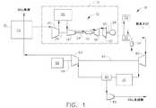
図1は、例示的なガスタービンエンジン組立体10を含む発電プラント8の概略図である。ガスタービンエンジン組立体10は、コアガスタービンエンジン12を含み、コアガスタービンエンジン12は、高圧圧縮機14、燃焼器16及び高圧タービン18を含む。ガスタービンエンジン組立体10はまた、低圧圧縮機20及び低圧タービン22を含む。高圧圧縮機14と高圧タービン18とは、第1のシャフト24によって結合され、また低圧圧縮機20は、第2のシャフト26によって中圧タービン(図示せず)に結合される。この例示的な実施形態では、低圧タービン22は、シャフト30を介して発電機28のような負荷に結合される。この例示的な実施形態では、コアガスタービンエンジン12は、オハイオ州シンシナチ所在のGeneral Electric Aircraft Enginesから入手可能なLMS100型である。 FIG. 1 is a schematic diagram of a power plant 8 that includes an exemplary gas
この例示的な実施形態では、ガスタービンエンジン組立体10は、高圧圧縮機14に流入する加圧空気流の温度を低下させるのを可能にする中間冷却器40を含むことができる。より具体的には、中間冷却器40は、低圧圧縮機20と高圧圧縮機14との間に流れ連通状態で結合されて、高圧圧縮機14に供給されるのに先立って、低圧圧縮機20から吐出された空気流を冷却するようになっている。この例示的な実施形態では、中間冷却器40は、それを通って流れる作動流体(図示せず)を有する水対空気熱交換器である。例えば、作動流体は、発電プラント8に近接して位置した例えば湖のような水域から送られた原水とすることができる。任意選択的に、中間冷却器40は、それを通って流れる冷却空気流(図示せず)を有する空気対空気熱交換器である。任意選択的に、ガスタービンエンジン組立体10は、中間冷却器40を含まない。 In the exemplary embodiment, gas
発電プラント8はまた、熱回収蒸気発生器(HRSG)50を含み、熱回収蒸気発生器(HRSG)50は、ガスタービンエンジン組立体10から吐出された比較的高温の排気ストリームを受けかつこの熱エネルギーを該HRSG50を通って流れる作動流体に伝達して蒸気を発生させるように構成されており、この例示的な実施形態では、発生した蒸気は、蒸気タービン52を駆動するために使用することができる。さらに、HRSG50の下流に排水管54が結合されて、HRSG50から吐出された排気ストリームから復水を実質的に除去する。 The power plant 8 also includes a heat recovery steam generator (HRSG) 50 that receives the relatively hot exhaust stream discharged from the gas
発電プラント8はまた、第2の低圧圧縮機60、膨張器62、及び該第2の低圧圧縮機60を膨張器62に結合するために使用するシャフト64を含む。本明細書で使用する場合の膨張器というのは、それを通して高圧ガスを膨張させて、一般的には低圧圧縮機60のような圧縮機を駆動するために使用する仕事を生み出す遠心又は軸流タービンを意味している。さらに、膨張器62はまた、当業者にはターボエクスパンダ又は膨張タービンとも呼ばれる。膨張器62は、シャフト68を介して電気モータ、ガスタービン又は往復動エンジンのような原動機66に結合される。従って、原動機66は、後述するように、膨張器62によって支援された状態で、低圧圧縮機60を駆動するために利用される。 The power plant 8 also includes a second
発電プラント8はまた、低圧圧縮機60と膨張器62との間に流れ連通状態で結合された第2の中間冷却器又は熱交換器70を含む。運転中に、低圧圧縮機60から吐出された排気ストリームは、該排気ストリームがCO2除去ユニット80及び膨張器62に供給されるのに先立って、中間冷却器70を通して送られて冷却される。この例示的な実施形態では、中間冷却器70は、それを通って流れる作動流体(図示せず)を有する水対空気熱交換器である。例えば、上述したように、作動流体は、発電プラント8に近接して位置した水域から送られた原水とすることができる。任意選択的に、中間冷却器70は、それを通って流れる冷却空気流(図示せず)を有する空気対空気熱交換器である。膨張器62から吐出された排気ストリームは次に、第3の熱交換器72に供給されて、後述するように、ガスタービンエンジン組立体10に供給される入口空気の作動温度を低下させるのを可能にする。The power plant 8 also includes a second intercooler or
運転時に、ガスタービンエンジン組立体10に吸い込まれた周囲空気は、熱交換器72を通って流れて、該ガスタービン組立体に供給される周囲空気の作動温度を低下させるのを可能にする。ガスタービンエンジン組立体10は、当技術分野で公知なように作動し、従って、約600〜1300°Fの温度を有する排気ストリームを生成する。ガスタービンエンジン組立体10から吐出された排気ストリームは、HRSG50を通して送られ、HRSG50において、排気ストリームからの熱エネルギーの大きな部分が、該HRSG50を通して送られる作動流体に伝達されて蒸気を発生し、この蒸気は、上述したように、蒸気タービン52を駆動するために利用することができる。HRSG50は、排気ストリームの作動温度を約75°F〜約125°Fの温度まで低下させるのを可能にする。この例示的な実施形態では、HRSG50は、排気ストリームの作動温度を約100°Fの温度まで低下させるのを可能にする。1つの実施形態では、排気ストリームはまた、付加的な熱交換器(図示せず)を通して送って該排気ストリームからさらに水を凝縮させ、この凝縮した水を次に、例えば排水管54を通して排出することができる。 In operation, ambient air drawn into the gas
比較的低温の乾燥排気ストリームは次に、この例示的な実施形態では、膨張器62によって、また必要に応じて原動機66によって駆動される第2の低圧圧縮機60内で加圧される。第2の低圧圧縮機60を利用して、該第2の低圧圧縮機60を通して送られる排気ストリームの作動圧力は、ガスタービンエンジン組立体10から吐出された排気ストリームの作動圧力よりも約4倍大きい圧力まで増大される。さらに、第2の低圧圧縮機60を通して排気ストリームを送ることにより、排気ストリームの温度が上昇することになる。第2の低圧圧縮機60から吐出された排気ストリームは次に、第2の中間冷却器70を通して送られて、その作動温度を低下させることが可能になる。この例示的な実施形態では、第2の中間冷却器70は、排気ストリームの作動温度を約100°Fの温度まで低下させるのを可能にする。 The relatively cool dry exhaust stream is then pressurized in this exemplary embodiment by a second low-
中間冷却器70から吐出された高圧かつ比較的乾燥したCO2濃厚排気ストリームは次に、アミン溶液と接触させられて、CO2分離器80を利用して、該排気ストリーム内に同伴されたCO2の実質的に全てが吸収されることが可能になる。さらに、CO2アミンストリームは、第2の中間冷却器70を利用して加熱して、アミン溶液からCO2を放出/蒸発させるのに必要な実際のエネルギー量を減少させるのを可能にすることができる。排気ストリームから抽出されたCO2は次に、圧縮機82内で圧縮される。圧縮CO2は、所望に応じて、ビン詰めにして販売するか、或いは枯渇した油井内に噴射させるための配管に吐出することができる。The high pressure and relatively dry CO2 rich exhaust stream discharged from the
CO2分離器から吐出されたCO2希薄排気ストリームは次に、膨張器62を通って膨張し、この膨張器62が加圧排気ガスから仕事を取り出して低圧圧縮機60を駆動し、従って排気ストリームの温度を大きく低下させるのを可能にする。例えば、1つの実施形態では、分離器62から吐出された排気ストリームの温度は、約30〜−30°Fである。この例示的な実施形態では、分離器62から吐出された排気ストリームの温度は、約−20°Fである。CO2 separator CO2 lean exhaust stream discharged from then expanded through the
比較的低温の排気ストリームは次に、熱交換器72を通して送られて、入口空気ストリームを冷却するのを可能にしかつガスタービンエンジン組立体10に送られる空気流の空気密度を高め、従ってコアガスタービンエンジン12の効率及び出力を増大させるのを可能にする。その結果、ガスタービンへの空気流の入口温度の低下は、その質量流量及び効率を増大させて、CO2隔離プロセスの経済的影響を軽減する。The relatively cool exhaust stream is then routed through
図2は、別の例示的な発電プラント100の概略図である。発電プラント100は、図1に示す発電プラント8と実質的に同様である。従って、図1に示す構成要素と同様な図2に示す構成要素は、同じ参照符号で特定することにする。この例示的な実施形態では、発電プラント100は、熱交換器72を含んでおらず、膨張器62から吐出された比較的低温の乾燥排気ストリームは、ガスタービンエンジン組立体10の入口内に直接吐出される第1の空気ストリーム部分110と、第2の低圧圧縮機の上流に配置された熱交換器120を通して送られる第2の空気ストリーム部分112とに分離される。 FIG. 2 is a schematic diagram of another
運転時に、第1の空気ストリーム110は、ガスタービンエンジン組立体10に供給される入口空気ストリーム内に直接送られる。より具体的には、新鮮な流入空気ストリーム内に依然として同伴されている全ての水分は、凝縮されて比較的小さな又は微小な水滴になり、それらの水滴は、空気ストリーム110と混合した時に微細な霧又はミストを生成する。霧又はミストは次に、低圧圧縮機20内に送り込まれ、低圧圧縮機20において、水滴は蒸気して、コアガスタービンエンジン12に供給される空気流の作動温度を低下させるのを可能にする。その結果、コアガスタービンエンジン12内へ送り込まれる空気流の温度が低下し、従って加圧プロセスに必要な仕事を減少させ、またガスタービンエンジン組立体10の全体効率を増大させる。ストリーム110の酸素成分は、ガスタービン10における燃焼プロセスによって減少する。新鮮な空気とのこのストリームの混合により、燃焼器16内での燃焼空気の正味酸素成分の減少が生じて、燃焼器におけるNOx形成を減少させることが可能になる。 During operation, the first air stream 110 is sent directly into the inlet air stream that is supplied to the gas
第2の排出空気ストリーム112は、熱交換器120を通して送られて、第2の低圧圧縮機60内に送り込まれるその排気ストリームから熱エネルギーを除去するのを可能にし、かつその排気ストリームが第2の低圧圧縮機60に流入するのに先立って、該排気ストリーム内に同伴された水を凝縮及び除去するのを可能にする。 The second
図3は、別の例示的な発電プラント200の概略図である。発電プラント200は、図1に示す発電プラント8と実質的に同様である。従って、図1に示す構成要素と同様な図3に示す構成要素は、同じ参照符号で特定することにする。この例示的な実施形態では、発電プラント200はまた、第1の除湿剤空気乾燥システム210及び第2の除湿剤空気乾燥システム212を含む。第1の除湿剤空気乾燥システム210は、熱交換器72の上流に配置されて、該第1の除湿剤空気乾燥システム210から吐出された排気ストリームが、熱交換器72を通してガスタービンエンジン組立体10内に送られるようになる。さらに、第2の除湿剤空気乾燥システム212は、CO2分離器80の下流にかつ膨張器62の上流に配置されて、該CO2分離器80から吐出されたCO2希薄排気ストリームが、膨張器62内に直接送り込まれるようになる。運転時に、第1の除湿剤空気乾燥システム210は、入口空気から水分を除去するのを可能して、このシステムが入口空気の温度を約40°F以下の温度まで低下させ、従ってガスタービンエンジン組立体10の表面上での氷生成を排除することを可能にする。さらに、第2の除湿剤空気乾燥システム212は、膨張器62に送られる排気ストリーム内に同伴された水分を除去するのを可能にし、膨張器62が排気ストリームからエネルギーを取り出すことを可能にして、該膨張器の出口温度が着氷条件よりも低くなることを可能にする。FIG. 3 is a schematic diagram of another
図4は、図3に示す発電プラント200で利用することができる例示的な除湿剤システム210の概略図である。この実施形態では、除湿剤システム210及び212は各々、空気接触器300、第1の熱交換器302、第2の熱交換器304、第3の熱交換器306、接触器ボイラ308、第1の除湿剤ポンプ310、第2の除湿剤ポンプ312及び冷却塔314を含む。 FIG. 4 is a schematic diagram of an
使用中に、湿潤入口空気は、空気接触器300を通して送られ、該空気接触器300において、入口空気の水分は、それを通って流れる除湿剤により実質的に吸収される。水分を含んだ液体除湿剤は、第1の除湿剤ポンプ310を利用して第1の熱交換器302を通して送られる。第1の熱交換器302は、それを通って流れる水分を含んだ除湿剤の温度を上昇させるために利用される。この例示的な実施形態では、水分を含んだ除湿剤の温度は、それを通って流れる作動流体を利用して高められ、この作動流体は、この例示的な実施形態では、比較的温かい液体除湿剤であり、システム210及び212をより明確に記述するために本明細書では「乾燥除湿剤」と呼ぶことにする。従って、温かい液体除湿剤を利用して、熱交換器302内で水分を含んだ除湿剤の作動温度を上昇させる。部分的に加熱された湿潤除湿剤は次に、熱交換器306を通して送られ、該熱交換器306において、ガスタービンエンジン排気ストリームの熱エネルギーは、湿潤除湿剤によって吸収されて、湿潤除湿剤の温度がさらに上昇し、この湿潤除湿剤は次に、接触器ボイラ308を通して送られ、該接触器ボイラ308において、除湿剤の水分が除去されて、乾燥除湿剤を生成する。乾燥除湿剤は次に、第2の除湿剤ポンプ312を利用して熱交換器302を通して送られて、上記したように湿潤除湿剤を加熱する。乾燥除湿剤は次に、熱交換器304を通して送られて、乾燥除湿剤の更なる冷却を可能にする。より具体的には、またこの例示的な実施形態では、熱交換器304は、冷却塔314から冷却水を受けて乾燥除湿剤を冷却するように構成された水対空気熱交換器である。冷却した乾燥液体除湿剤は次に、空気接触器300を通して送られ、該空気接触器300において、このプロセスが連続的に反復されて、入口空気から水分が除去される。 During use, the wet inlet air is routed through the
本明細書に記載したのは、発電プラントのエミッションを低減すると共に発電プラントの効率を増大させるための方法及びシステムである。本方法は、ガスタービンエンジン組立体から吐出された排気ガスの作動圧力を増大させる段階と、CO2分離器を利用して排気ガス内に同伴された実質的に全てのCO2を分離して、CO2希薄空気ストリームを生成する段階と、CO2希薄空気ストリームの作動温度を低下させる段階と、冷却CO2希薄空気ストリームを利用して、ガスタービンエンジン組立体に流入する空気の作動温度を低下させるのを可能する段階とを含む。Described herein are methods and systems for reducing power plant emissions and increasing power plant efficiency. The method includes increasing the operating pressure of exhaust gas discharged from a gas turbine engine assembly, and utilizing a CO2 separator to separate substantially all of the CO2 entrained in the exhaust gas. and generating a CO2 lean air stream, comprising the steps of reducing an operating temperature of the CO2 lean air stream, using a cooled CO2 lean air stream, the operating temperature of the air entering the gas turbine engine assembly Allowing to be reduced.
より具体的には、ガスタービンエンジンへの空気流の入口温度を低下させることにより、その質量流量及び効率を増大させることが可能になり、従って本明細書に記述したCO2隔離プロセスの経済的影響を軽減する。さらに、CO2抽出システムの空気循環機械の排気を使用してガスタービン入口空気流を冷却して、発電プラント全体に対するCO2隔離システムの影響を減少させることができる。本明細書に記述したCO2抽出システムはまた、あらゆる複合サイクルガスタービン発電プラントと共に使用して、排気ガスからCO2を抽出することができ、従って例えば地中にCO2を再噴射して石油回収を高めるようにするか或いはCO2をビン詰めして販売するのを可能にすることによって温室効果ガスの排出を低減することができる。More specifically, by reducing the inlet temperature of the air flow to the gas turbine engine, it is possible to increase its mass flow rate and efficiency, and thus the economics of the CO2 sequestration process described herein. Reduce the impact. Further, the exhaust of the CO2 extraction system air circulation machine can be used to cool the gas turbine inlet air flow to reduce the impact of the CO2 isolation system on the entire power plant. The CO2 extraction system described herein can also be used with any combined cycle gas turbine power plant to extract CO2 from exhaust gas, thus re-injecting CO2 into the ground to produce petroleum, for example. Greenhouse gas emissions can be reduced by increasing the recovery or by allowing CO2 to be bottled and sold.
様々な特定の実施形態に関して本発明を説明してきたが、本発明が特許請求の範囲の技術思想及び技術的範囲内の変更で実施することができることは、当業者には明らかであろう。 While the invention has been described in terms of various specific embodiments, those skilled in the art will recognize that the invention can be practiced with modification within the spirit and scope of the claims.
8 発電プラント
10 ガスタービンエンジン組立体
12 コアガスタービンエンジン
14 高圧圧縮機
16 燃焼器
18 高圧タービン
20 低圧圧縮機
22 低圧タービン
24 第1のシャフト
26 第2のシャフト
28 発電機
30 シャフト
40 中間冷却器
50 熱回収蒸気発生器(HRSG)
52 蒸気タービン
54 排水管
60 低圧圧縮機
62 膨張器
64 シャフト
66 原動機
68 シャフト
70 第2の中間冷却熱交換器
72 第3の熱交換器
80 CO2分離器
82 圧縮機
100 発電プラント
110 第1の空気ストリーム部分
112 第2の空気ストリーム部分
120 熱交換器
200 発電プラント
210 除湿剤空気乾燥システム
212 除湿剤空気乾燥システム
300 空気接触器
302 第1の熱交換器
304 第2の熱交換器
306 第3の熱交換器
308 接触器ボイラ
310 第1の除湿剤ポンプ
312 第2の除湿剤ポンプ
314 冷却塔8
52
Claims (5)
Translated fromJapaneseコアガスタービンエンジン(12)を含むガスタービンエンジン組立体(10)と、
前記ガスタービンエンジン組立体と流れ連通し、ガスタービンエンジン組立体排気ストリームからCO2を除去してCO2希薄排気ストリームを生成するように構成された二酸化炭素(CO2)分離器(80)と、
前記ガスタービンエンジン組立体排気ストリームの作動圧力を増大させるように構成された圧縮機(60)と
を含み、
前記圧縮機から吐出された排気ストリームは、前記CO2分離器(80)に供給されるのに先立って第1の熱交換器(70)を通されて冷却され、
前記発電プラント(8)は、前記CO2希薄排気ストリームの作動温度を低下させて、該冷却CO2希薄排気ストリームを利用して前記ガスタービンエンジン組立体に流入する空気の作動温度を低下させるように構成された膨張器(62)を更に含む
ことを特徴とする、発電プラント(8)。A power plant (8),
A gas turbine engine assembly (10)including a core gas turbine engine (12) ;
The gas turbine engine assembly through steric and flow communication, configured carbon dioxide to produce a CO2 lean exhaust stream todivided the CO2 from the gas turbine engineassembly exhaust stream (CO2) separator (80) When,
A compressor (60) configured to increase the operating pressure of the gas turbine engine assembly exhaust stream;
Including
The exhaust stream discharged from the compressor iscooled by passing through a first heat exchanger (70) prior to being supplied to theCO2separator (80),
The power plant (8), said lowering the operating temperature of the CO2 lean exhaust stream, the cooling CO2 by using a lean exhaust stream to reduce the operating temperature of the air flowing into the gas turbine engine assemblyFurther comprising an inflator (62) configured in
A power plant (8), characterized in that .
Further comprising a first dehumidifying agent air drying system configured todivided water from the inlet air stream of a gas turbine engine (210), the power plantaccording toany one of claims 1to 4 (8 ).
Applications Claiming Priority (2)
| Application Number | Priority Date | Filing Date | Title |
|---|---|---|---|
| US11/539,651 | 2006-10-09 | ||
| US11/539,651US7942008B2 (en) | 2006-10-09 | 2006-10-09 | Method and system for reducing power plant emissions |
Publications (2)
| Publication Number | Publication Date |
|---|---|
| JP2008095686A JP2008095686A (en) | 2008-04-24 |
| JP5100294B2true JP5100294B2 (en) | 2012-12-19 |
Family
ID=38935992
Family Applications (1)
| Application Number | Title | Priority Date | Filing Date |
|---|---|---|---|
| JP2007262348AExpired - Fee RelatedJP5100294B2 (en) | 2006-10-09 | 2007-10-05 | System for reducing power plant emissions |
Country Status (5)
| Country | Link |
|---|---|
| US (2) | US7942008B2 (en) |
| EP (1) | EP1918014B1 (en) |
| JP (1) | JP5100294B2 (en) |
| CA (1) | CA2604630C (en) |
| DE (1) | DE602007013671D1 (en) |
Families Citing this family (101)
| Publication number | Priority date | Publication date | Assignee | Title |
|---|---|---|---|---|
| US20080066469A1 (en)* | 2006-09-15 | 2008-03-20 | Scherzer Paul L | System and method for generating electrical energy utilizing recaptured carbon dioxide |
| US7966829B2 (en)* | 2006-12-11 | 2011-06-28 | General Electric Company | Method and system for reducing CO2 emissions in a combustion stream |
| EP2085587A1 (en)* | 2008-02-04 | 2009-08-05 | ALSTOM Technology Ltd | Low carbon emissions combined cycle power plant and process |
| WO2009120779A2 (en) | 2008-03-28 | 2009-10-01 | Exxonmobil Upstream Research Company | Low emission power generation and hydrocarbon recovery systems and methods |
| EP2276559A4 (en) | 2008-03-28 | 2017-10-18 | Exxonmobil Upstream Research Company | Low emission power generation and hydrocarbon recovery systems and methods |
| US8397482B2 (en) | 2008-05-15 | 2013-03-19 | General Electric Company | Dry 3-way catalytic reduction of gas turbine NOx |
| US20100071878A1 (en)* | 2008-09-19 | 2010-03-25 | General Electric Company | System and method for cooling using system exhaust |
| EA026915B1 (en) | 2008-10-14 | 2017-05-31 | Эксонмобил Апстрим Рисерч Компани | Methods and systems for controlling the products of combustion |
| US7980083B2 (en)* | 2008-12-22 | 2011-07-19 | General Electric Company | Method and system for operating a combined cycle power plant |
| CH700310A1 (en)* | 2009-01-23 | 2010-07-30 | Alstom Technology Ltd | Processes for CO2 capture from a combined cycle power plant and combined cycle power plant with a gas turbine with flow separation and recirculation. |
| SE0900236A1 (en)* | 2009-02-24 | 2010-08-25 | Euroturbine Ab | Procedure for operating a gas turbine power plant and a gas turbine power plant |
| WO2010141777A1 (en) | 2009-06-05 | 2010-12-09 | Exxonmobil Upstream Research Company | Combustor systems and methods for using same |
| US8387355B2 (en)* | 2009-07-15 | 2013-03-05 | Ormat Technologies Inc. | Gas turbine exhaust gas cooling system |
| JP5427506B2 (en)* | 2009-08-07 | 2014-02-26 | 三菱重工業株式会社 | Intake humidity control apparatus for gas turbine, gas turbine and gas turbine combined cycle power plant including the same, and output increasing method |
| US20110068585A1 (en)* | 2009-09-24 | 2011-03-24 | Alstom Technology Ltd | Method and system for capturing and utilizing energy generated in a flue gas stream processing system |
| EP2499332B1 (en) | 2009-11-12 | 2017-05-24 | Exxonmobil Upstream Research Company | Integrated system for power generation and method for low emission hydrocarbon recovery with power generation |
| US20110265445A1 (en)* | 2010-04-30 | 2011-11-03 | General Electric Company | Method for Reducing CO2 Emissions in a Combustion Stream and Industrial Plants Utilizing the Same |
| US20130104562A1 (en)* | 2010-07-02 | 2013-05-02 | Russell H. Oelfke | Low Emission Tripe-Cycle Power Generation Systems and Methods |
| CN102971508B (en) | 2010-07-02 | 2016-06-01 | 埃克森美孚上游研究公司 | CO2 separation system and method for separating CO2 |
| MX354587B (en) | 2010-07-02 | 2018-03-12 | Exxonmobil Upstream Res Company Star | Stoichiometric combustion of enriched air with exhaust gas recirculation. |
| MY156099A (en)* | 2010-07-02 | 2016-01-15 | Exxonmobil Upstream Res Co | Systems and methods for controlling combustion of a fuel |
| TWI564475B (en) | 2010-07-02 | 2017-01-01 | 艾克頌美孚上游研究公司 | Low emission triple-cycle power generation systems and methods |
| CA2801492C (en) | 2010-07-02 | 2017-09-26 | Exxonmobil Upstream Research Company | Stoichiometric combustion with exhaust gas recirculation and direct contact cooler |
| US20120023892A1 (en)* | 2010-07-30 | 2012-02-02 | General Electric Company | Systems and methods for co2 capture |
| US20120023947A1 (en)* | 2010-07-30 | 2012-02-02 | General Electric Company | Systems and methods for co2 capture |
| US9399950B2 (en) | 2010-08-06 | 2016-07-26 | Exxonmobil Upstream Research Company | Systems and methods for exhaust gas extraction |
| EP2601393B1 (en) | 2010-08-06 | 2020-01-15 | Exxonmobil Upstream Research Company | Systems and methods for optimizing stoichiometric combustion |
| US9856769B2 (en) | 2010-09-13 | 2018-01-02 | Membrane Technology And Research, Inc. | Gas separation process using membranes with permeate sweep to remove CO2 from combustion exhaust |
| US8220248B2 (en)* | 2010-09-13 | 2012-07-17 | Membrane Technology And Research, Inc | Power generation process with partial recycle of carbon dioxide |
| US8220247B2 (en)* | 2010-09-13 | 2012-07-17 | Membrane Technology And Research, Inc. | Power generation process with partial recycle of carbon dioxide |
| US9457313B2 (en) | 2010-09-13 | 2016-10-04 | Membrane Technology And Research, Inc. | Membrane technology for use in a power generation process |
| US20120180512A1 (en)* | 2011-01-13 | 2012-07-19 | General Electric Company | Water recovery system for a cooling tower |
| TWI593872B (en) | 2011-03-22 | 2017-08-01 | 艾克頌美孚上游研究公司 | Integrated system and method of generating power |
| TWI563165B (en) | 2011-03-22 | 2016-12-21 | Exxonmobil Upstream Res Co | Power generation system and method for generating power |
| TWI563166B (en) | 2011-03-22 | 2016-12-21 | Exxonmobil Upstream Res Co | Integrated generation systems and methods for generating power |
| TWI564474B (en) | 2011-03-22 | 2017-01-01 | 艾克頌美孚上游研究公司 | Integrated systems for controlling stoichiometric combustion in turbine systems and methods of generating power using the same |
| US9810050B2 (en) | 2011-12-20 | 2017-11-07 | Exxonmobil Upstream Research Company | Enhanced coal-bed methane production |
| WO2013147953A1 (en)* | 2011-12-30 | 2013-10-03 | Rolls-Royce North American Technologies Inc. | Aircraft propulsion gas turbine engine with heat exchange |
| US9021810B2 (en) | 2012-01-27 | 2015-05-05 | The University Of Kentucky Research Foundation | Fossil-fuel-fired power plant |
| DE102012203973A1 (en)* | 2012-03-14 | 2013-09-19 | Siemens Aktiengesellschaft | Process for the re-evaporation of liquefied natural gas |
| US9353682B2 (en) | 2012-04-12 | 2016-05-31 | General Electric Company | Methods, systems and apparatus relating to combustion turbine power plants with exhaust gas recirculation |
| AU2013245959B2 (en)* | 2012-04-12 | 2016-03-31 | Exxonmobil Upstream Research Company | System and method for a stoichiometric exhaust gas recirculation gas turbine system |
| US10273880B2 (en) | 2012-04-26 | 2019-04-30 | General Electric Company | System and method of recirculating exhaust gas for use in a plurality of flow paths in a gas turbine engine |
| US9784185B2 (en) | 2012-04-26 | 2017-10-10 | General Electric Company | System and method for cooling a gas turbine with an exhaust gas provided by the gas turbine |
| US9869279B2 (en) | 2012-11-02 | 2018-01-16 | General Electric Company | System and method for a multi-wall turbine combustor |
| US10107495B2 (en) | 2012-11-02 | 2018-10-23 | General Electric Company | Gas turbine combustor control system for stoichiometric combustion in the presence of a diluent |
| US9611756B2 (en) | 2012-11-02 | 2017-04-04 | General Electric Company | System and method for protecting components in a gas turbine engine with exhaust gas recirculation |
| US9631815B2 (en) | 2012-12-28 | 2017-04-25 | General Electric Company | System and method for a turbine combustor |
| US9599070B2 (en) | 2012-11-02 | 2017-03-21 | General Electric Company | System and method for oxidant compression in a stoichiometric exhaust gas recirculation gas turbine system |
| US9803865B2 (en) | 2012-12-28 | 2017-10-31 | General Electric Company | System and method for a turbine combustor |
| US9574496B2 (en) | 2012-12-28 | 2017-02-21 | General Electric Company | System and method for a turbine combustor |
| US10161312B2 (en) | 2012-11-02 | 2018-12-25 | General Electric Company | System and method for diffusion combustion with fuel-diluent mixing in a stoichiometric exhaust gas recirculation gas turbine system |
| US9708977B2 (en) | 2012-12-28 | 2017-07-18 | General Electric Company | System and method for reheat in gas turbine with exhaust gas recirculation |
| US10215412B2 (en) | 2012-11-02 | 2019-02-26 | General Electric Company | System and method for load control with diffusion combustion in a stoichiometric exhaust gas recirculation gas turbine system |
| US9341412B2 (en)* | 2012-12-18 | 2016-05-17 | General Electric Company | Methods and systems for reducing silica recession in silicon-containing materials |
| US10208677B2 (en) | 2012-12-31 | 2019-02-19 | General Electric Company | Gas turbine load control system |
| US9581081B2 (en) | 2013-01-13 | 2017-02-28 | General Electric Company | System and method for protecting components in a gas turbine engine with exhaust gas recirculation |
| US9512759B2 (en) | 2013-02-06 | 2016-12-06 | General Electric Company | System and method for catalyst heat utilization for gas turbine with exhaust gas recirculation |
| TW201502356A (en)* | 2013-02-21 | 2015-01-16 | Exxonmobil Upstream Res Co | Reducing oxygen in a gas turbine exhaust |
| US9938861B2 (en) | 2013-02-21 | 2018-04-10 | Exxonmobil Upstream Research Company | Fuel combusting method |
| WO2014133406A1 (en) | 2013-02-28 | 2014-09-04 | General Electric Company | System and method for a turbine combustor |
| US20140250945A1 (en) | 2013-03-08 | 2014-09-11 | Richard A. Huntington | Carbon Dioxide Recovery |
| CA2902479C (en) | 2013-03-08 | 2017-11-07 | Exxonmobil Upstream Research Company | Power generation and methane recovery from methane hydrates |
| US9618261B2 (en) | 2013-03-08 | 2017-04-11 | Exxonmobil Upstream Research Company | Power generation and LNG production |
| TW201500635A (en) | 2013-03-08 | 2015-01-01 | Exxonmobil Upstream Res Co | Processing exhaust for use in enhanced oil recovery |
| US9523537B2 (en)* | 2013-03-11 | 2016-12-20 | General Electric Company | Desiccant based chilling system |
| US9835089B2 (en) | 2013-06-28 | 2017-12-05 | General Electric Company | System and method for a fuel nozzle |
| US9617914B2 (en) | 2013-06-28 | 2017-04-11 | General Electric Company | Systems and methods for monitoring gas turbine systems having exhaust gas recirculation |
| US9631542B2 (en) | 2013-06-28 | 2017-04-25 | General Electric Company | System and method for exhausting combustion gases from gas turbine engines |
| TWI654368B (en) | 2013-06-28 | 2019-03-21 | 美商艾克頌美孚上游研究公司 | System, method and media for controlling exhaust gas flow in an exhaust gas recirculation gas turbine system |
| US9903588B2 (en) | 2013-07-30 | 2018-02-27 | General Electric Company | System and method for barrier in passage of combustor of gas turbine engine with exhaust gas recirculation |
| US9587510B2 (en) | 2013-07-30 | 2017-03-07 | General Electric Company | System and method for a gas turbine engine sensor |
| US9951658B2 (en) | 2013-07-31 | 2018-04-24 | General Electric Company | System and method for an oxidant heating system |
| US9752458B2 (en) | 2013-12-04 | 2017-09-05 | General Electric Company | System and method for a gas turbine engine |
| US10030588B2 (en) | 2013-12-04 | 2018-07-24 | General Electric Company | Gas turbine combustor diagnostic system and method |
| US10227920B2 (en) | 2014-01-15 | 2019-03-12 | General Electric Company | Gas turbine oxidant separation system |
| US9915200B2 (en) | 2014-01-21 | 2018-03-13 | General Electric Company | System and method for controlling the combustion process in a gas turbine operating with exhaust gas recirculation |
| US9863267B2 (en) | 2014-01-21 | 2018-01-09 | General Electric Company | System and method of control for a gas turbine engine |
| US10079564B2 (en) | 2014-01-27 | 2018-09-18 | General Electric Company | System and method for a stoichiometric exhaust gas recirculation gas turbine system |
| US10047633B2 (en) | 2014-05-16 | 2018-08-14 | General Electric Company | Bearing housing |
| US10655542B2 (en) | 2014-06-30 | 2020-05-19 | General Electric Company | Method and system for startup of gas turbine system drive trains with exhaust gas recirculation |
| US9885290B2 (en) | 2014-06-30 | 2018-02-06 | General Electric Company | Erosion suppression system and method in an exhaust gas recirculation gas turbine system |
| US10060359B2 (en) | 2014-06-30 | 2018-08-28 | General Electric Company | Method and system for combustion control for gas turbine system with exhaust gas recirculation |
| JP6223955B2 (en) | 2014-12-11 | 2017-11-01 | 三菱日立パワーシステムズ株式会社 | Solar power generation system |
| US9819292B2 (en) | 2014-12-31 | 2017-11-14 | General Electric Company | Systems and methods to respond to grid overfrequency events for a stoichiometric exhaust recirculation gas turbine |
| US9869247B2 (en) | 2014-12-31 | 2018-01-16 | General Electric Company | Systems and methods of estimating a combustion equivalence ratio in a gas turbine with exhaust gas recirculation |
| US10788212B2 (en) | 2015-01-12 | 2020-09-29 | General Electric Company | System and method for an oxidant passageway in a gas turbine system with exhaust gas recirculation |
| US10094566B2 (en) | 2015-02-04 | 2018-10-09 | General Electric Company | Systems and methods for high volumetric oxidant flow in gas turbine engine with exhaust gas recirculation |
| US10316746B2 (en) | 2015-02-04 | 2019-06-11 | General Electric Company | Turbine system with exhaust gas recirculation, separation and extraction |
| US10253690B2 (en) | 2015-02-04 | 2019-04-09 | General Electric Company | Turbine system with exhaust gas recirculation, separation and extraction |
| US10267270B2 (en) | 2015-02-06 | 2019-04-23 | General Electric Company | Systems and methods for carbon black production with a gas turbine engine having exhaust gas recirculation |
| US10145269B2 (en) | 2015-03-04 | 2018-12-04 | General Electric Company | System and method for cooling discharge flow |
| US10480792B2 (en) | 2015-03-06 | 2019-11-19 | General Electric Company | Fuel staging in a gas turbine engine |
| JP6746689B2 (en)* | 2015-09-01 | 2020-08-26 | 8 リバーズ キャピタル,エルエルシー | System and method for power production using a nested CO2 cycle |
| US10280760B2 (en) | 2015-09-30 | 2019-05-07 | General Electric Company | Turbine engine assembly and method of assembling the same |
| CN106208047B (en)* | 2016-08-08 | 2018-08-17 | 国网天津市电力公司 | A kind of power grid unit output method of adjustment considering energy-saving and emission-reduction benefit |
| US9782718B1 (en) | 2016-11-16 | 2017-10-10 | Membrane Technology And Research, Inc. | Integrated gas separation-turbine CO2 capture processes |
| US11193421B2 (en)* | 2019-06-07 | 2021-12-07 | Saudi Arabian Oil Company | Cold recycle process for gas turbine inlet air cooling |
| US11635255B1 (en)* | 2022-04-08 | 2023-04-25 | Axip Energy Services, Lp | Liquid or supercritical carbon dioxide capture from exhaust gas |
| WO2023249815A1 (en)* | 2022-06-19 | 2023-12-28 | Yiding Cao | Air-water thermal power plants |
| US20240252979A1 (en)* | 2023-01-27 | 2024-08-01 | Sustainable Energy Solutions, Inc. | Sensible Heat Exchanger and Dryer |
Family Cites Families (26)
| Publication number | Priority date | Publication date | Assignee | Title |
|---|---|---|---|---|
| NL8001472A (en)* | 1980-03-12 | 1981-10-01 | Tno | INSTALLATION FOR HEAT RECOVERY ON COMBUSTION MACHINE. |
| US5459994A (en) | 1993-05-28 | 1995-10-24 | Praxair Technology, Inc. | Gas turbine-air separation plant combination |
| JP2856552B2 (en)* | 1993-12-10 | 1999-02-10 | キャボット コーポレイション | Improved co-cycle plant using liquefied natural gas as fuel. |
| US5442904A (en)* | 1994-03-21 | 1995-08-22 | Shnaid; Isaac | Gas turbine with bottoming air turbine cycle |
| JP3004545B2 (en)* | 1994-08-10 | 2000-01-31 | 川崎重工業株式会社 | Combustion turbine intake cooling system |
| JP3368487B2 (en)* | 1995-04-04 | 2003-01-20 | 日本酸素株式会社 | Inlet air cooling device in gas turbine power generation system and method of operating the same |
| US5724805A (en)* | 1995-08-21 | 1998-03-10 | University Of Massachusetts-Lowell | Power plant with carbon dioxide capture and zero pollutant emissions |
| EP0859136A1 (en)* | 1997-02-17 | 1998-08-19 | N.V. Kema | Gas turbine with energy recovering |
| NO308399B1 (en) | 1997-06-06 | 2000-09-11 | Norsk Hydro As | Process for generating power and / or heat |
| CA2304226A1 (en) | 1997-09-15 | 1999-03-25 | Finn Patrick Nilsen | Separation of acid gases from gas mixtures |
| NO990812L (en) | 1999-02-19 | 2000-08-21 | Norsk Hydro As | Method for removing and recovering CO2 from exhaust gas |
| JP2002129980A (en)* | 2000-10-25 | 2002-05-09 | Osaka Gas Co Ltd | Combined cycle power generation plant |
| FR2825935B1 (en) | 2001-06-14 | 2003-08-22 | Inst Francais Du Petrole | LOW CO2 EMISSIONS POWER GENERATOR AND ASSOCIATED METHOD |
| US7191587B2 (en)* | 2002-11-13 | 2007-03-20 | American Air Liquide, Inc. | Hybrid oxygen-fired power generation system |
| DE10325111A1 (en)* | 2003-06-02 | 2005-01-05 | Alstom Technology Ltd | Method for generating energy in a gas turbine comprehensive power generation plant and power plant for performing the method |
| US7299619B2 (en)* | 2003-12-13 | 2007-11-27 | Siemens Power Generation, Inc. | Vaporization of liquefied natural gas for increased efficiency in power cycles |
| DE10360951A1 (en) | 2003-12-23 | 2005-07-28 | Alstom Technology Ltd | Thermal power plant with sequential combustion and reduced CO2 emissions and method of operating such a plant |
| DE102004039164A1 (en) | 2004-08-11 | 2006-03-02 | Alstom Technology Ltd | Method for generating energy in a gas turbine comprehensive power generation plant and power generation plant for performing the method |
| DE102005015151A1 (en) | 2005-03-31 | 2006-10-26 | Alstom Technology Ltd. | Gas turbine system for power station, has control device to control volume flow and/or temperature of combustion exhaust gas, such that fresh gas-exhaust gas-mixture entering into compressor of turbo group has preset reference temperature |
| US7266940B2 (en)* | 2005-07-08 | 2007-09-11 | General Electric Company | Systems and methods for power generation with carbon dioxide isolation |
| US7895822B2 (en)* | 2006-11-07 | 2011-03-01 | General Electric Company | Systems and methods for power generation with carbon dioxide isolation |
| US20090223229A1 (en)* | 2006-12-19 | 2009-09-10 | Hua Wang | Method and System for Using Low BTU Fuel Gas in a Gas Turbine |
| US7966829B2 (en)* | 2006-12-11 | 2011-06-28 | General Electric Company | Method and system for reducing CO2 emissions in a combustion stream |
| US8850789B2 (en)* | 2007-06-13 | 2014-10-07 | General Electric Company | Systems and methods for power generation with exhaust gas recirculation |
| US8397482B2 (en)* | 2008-05-15 | 2013-03-19 | General Electric Company | Dry 3-way catalytic reduction of gas turbine NOx |
| US20100107592A1 (en)* | 2008-11-04 | 2010-05-06 | General Electric Company | System and method for reducing corrosion in a gas turbine system |
- 2006
- 2006-10-09USUS11/539,651patent/US7942008B2/ennot_activeExpired - Fee Related
- 2007
- 2007-09-27CACA2604630Apatent/CA2604630C/ennot_activeExpired - Fee Related
- 2007-10-03DEDE602007013671Tpatent/DE602007013671D1/enactiveActive
- 2007-10-03EPEP07117812Apatent/EP1918014B1/ennot_activeNot-in-force
- 2007-10-05JPJP2007262348Apatent/JP5100294B2/ennot_activeExpired - Fee Related
- 2011
- 2011-04-08USUS13/082,960patent/US8104259B2/ennot_activeExpired - Fee Related
Also Published As
| Publication number | Publication date |
|---|---|
| JP2008095686A (en) | 2008-04-24 |
| CA2604630A1 (en) | 2008-04-09 |
| US20110192168A1 (en) | 2011-08-11 |
| EP1918014B1 (en) | 2011-04-06 |
| EP1918014A1 (en) | 2008-05-07 |
| US8104259B2 (en) | 2012-01-31 |
| US7942008B2 (en) | 2011-05-17 |
| CA2604630C (en) | 2015-02-10 |
| US20080083226A1 (en) | 2008-04-10 |
| DE602007013671D1 (en) | 2011-05-19 |
Similar Documents
| Publication | Publication Date | Title |
|---|---|---|
| JP5100294B2 (en) | System for reducing power plant emissions | |
| KR101378195B1 (en) | Power plants that utilize gas turbines for power generation and processes for lowering co2 emissions | |
| US8171718B2 (en) | Methods and systems involving carbon sequestration and engines | |
| CN101201171B (en) | Method and system for reducing CO2 emissions in a combustion stream | |
| AU2009270451B2 (en) | Method and device for separating carbon dioxide from a waste gas of a fossil fuel-operated power plant | |
| JP5383708B2 (en) | Low carbon emission combined cycle power plant and method | |
| US20180216532A1 (en) | System and method for treating exhaust gas | |
| JP2012031862A (en) | System and method for co2 capture | |
| MX2013009836A (en) | Methods of varying low emission turbine gas recycle circuits and systems and apparatus related thereto. | |
| US20120023892A1 (en) | Systems and methods for co2 capture | |
| US12409411B2 (en) | Exhaust gas processing equipment and gas turbine plant | |
| US20140020388A1 (en) | System for improved carbon dioxide capture and method thereof | |
| JP2024100856A (en) | Gas turbine plant, and plant | |
| JP2025521683A (en) | Combined cycle power plant with exhaust gas recirculation intercooling | |
| GB2571355A (en) | Method | |
| CN119678005A (en) | Carbon capture system and method with exhaust gas recirculation | |
| Jonshagen et al. | Optimal Combined cycle for CO2 capture with EGR | |
| Utilizing et al. | Postcombustion CO2 Capture for |
Legal Events
| Date | Code | Title | Description |
|---|---|---|---|
| A621 | Written request for application examination | Free format text:JAPANESE INTERMEDIATE CODE: A621 Effective date:20100930 | |
| RD04 | Notification of resignation of power of attorney | Free format text:JAPANESE INTERMEDIATE CODE: A7424 Effective date:20100930 | |
| A131 | Notification of reasons for refusal | Free format text:JAPANESE INTERMEDIATE CODE: A131 Effective date:20110913 | |
| A601 | Written request for extension of time | Free format text:JAPANESE INTERMEDIATE CODE: A601 Effective date:20111212 | |
| A602 | Written permission of extension of time | Free format text:JAPANESE INTERMEDIATE CODE: A602 Effective date:20111215 | |
| A521 | Request for written amendment filed | Free format text:JAPANESE INTERMEDIATE CODE: A523 Effective date:20120313 | |
| TRDD | Decision of grant or rejection written | ||
| A01 | Written decision to grant a patent or to grant a registration (utility model) | Free format text:JAPANESE INTERMEDIATE CODE: A01 Effective date:20120911 | |
| A01 | Written decision to grant a patent or to grant a registration (utility model) | Free format text:JAPANESE INTERMEDIATE CODE: A01 | |
| A61 | First payment of annual fees (during grant procedure) | Free format text:JAPANESE INTERMEDIATE CODE: A61 Effective date:20120925 | |
| FPAY | Renewal fee payment (event date is renewal date of database) | Free format text:PAYMENT UNTIL: 20151005 Year of fee payment:3 | |
| R150 | Certificate of patent or registration of utility model | Free format text:JAPANESE INTERMEDIATE CODE: R150 | |
| R250 | Receipt of annual fees | Free format text:JAPANESE INTERMEDIATE CODE: R250 | |
| LAPS | Cancellation because of no payment of annual fees |