JP5099566B2 - Waterproof connector - Google Patents
Waterproof connectorDownload PDFInfo
- Publication number
- JP5099566B2 JP5099566B2JP2010198528AJP2010198528AJP5099566B2JP 5099566 B2JP5099566 B2JP 5099566B2JP 2010198528 AJP2010198528 AJP 2010198528AJP 2010198528 AJP2010198528 AJP 2010198528AJP 5099566 B2JP5099566 B2JP 5099566B2
- Authority
- JP
- Japan
- Prior art keywords
- plug
- receptacle
- shield member
- substrate
- housing
- Prior art date
- Legal status (The legal status is an assumption and is not a legal conclusion. Google has not performed a legal analysis and makes no representation as to the accuracy of the status listed.)
- Expired - Fee Related
Links
Images


Landscapes
- Connector Housings Or Holding Contact Members (AREA)
- Details Of Connecting Devices For Male And Female Coupling (AREA)
Description
Translated fromJapanese本発明は、Micro―USBコネクタ、USBコネクタ等のコネクタであって、防水機能を有する防水機能付きコネクタに関する。 The present invention relates to a connector with a waterproof function, such as a Micro-USB connector or a USB connector, which has a waterproof function.
従来、Micro−USBコネクタやUSBコネクタ等のコネクタにあっては、プラグがレセプタクルに挿入されることにより互いの接触端子が接触し、電気的に接続がなされるようにしたものが提供されている(例えば、特許文献1)。 Conventionally, in a connector such as a Micro-USB connector or a USB connector, a plug is inserted into a receptacle so that the contact terminals come into contact with each other and are electrically connected. (For example, patent document 1).
この種のMicro−USBコネクタやUSBコネクタ等のコネクタでは、プラグが挿入されるプラグ挿入部100を有するハウジング101を備え、このハウジング101は、レセプタクル側接触端子102,102...を支持するモールド部材103と、導電性金属材を折り曲げ加工することにより形成された筒状のシールド部材104とをもって構成されたものが知られている。 This type of connector, such as a Micro-USB connector or a USB connector, includes a
モールド部材103は、図11に示すように、シールド部材104の後端部に嵌め込まれる後壁部105と、後壁部の前面に突出した平板状の端子支持部106とを有し、絶縁性樹脂部材をもって成形されている。 As shown in FIG. 11, the
このモールド部材103には、複数のレセプタクル側接触端子102,102...が一体的に成形されることにより支持されている。 A plurality of receptacle-
この接触端子は、端子支持部106の上面にプラグ側接触端子と接触される接触片102aを露出させた状態、且つ基板に接続される基板接触片102bを後壁部105の後側面より後方に突出させた状態になっている。 In this contact terminal, the
この種のコネクタでは、シールド部材104とモールド部材103とを別個に成形しておき、モールド部材103をシールド部材104の背面側より挿入し、シールド部材104の後端部に嵌め込み、シールド部材の天板の後縁部より固定用片部107及び基板接続端子部108,108を下向きに折り曲げてモールド部材後壁部105の後背面を押圧させて固定する構造になっている。 In this type of connector, the
また、シールド部材104には、天板又は底板を貫通した係止用孔109,109が形成されており、この孔にプラグに形成された係止用弾性片が嵌り込むことにより互いに係止され、抜け止めがなされるようになっている。 The
上述した従来のコネクタは、シールド部材にモールド部材の後壁部を嵌め込み組立てる構造であるため、各部材間即ち、シールド部材とモールド部材との間に嵌め合い用の隙間(クリアランス)を有しており、プラグ挿入部内に水滴等が侵入した際にこの隙間から水滴が当該コネクタを取り付けた機器の内部に侵入してしまう虞があるという問題があった。 Since the conventional connector described above has a structure in which the rear wall portion of the mold member is fitted and assembled to the shield member, there is a fitting clearance (clearance) between the members, that is, between the shield member and the mold member. In addition, when water drops or the like enter the plug insertion portion, there is a problem that the water drops may enter the inside of the device to which the connector is attached from this gap.
また、この種のコネクタでは、シールド部材を貫通する係止孔を形成したことにより、プラグ挿入部の開口部より侵入した水滴等がこの係止孔から機器内部に侵入してしまう虞があるという問題があった。 Further, in this type of connector, the formation of a locking hole that penetrates the shield member may cause water droplets or the like that have entered from the opening of the plug insertion portion to enter the device from the locking hole. There was a problem.
本発明は、このような従来の問題に鑑み、防水機能を有する防水機能付きコネクタの提供を目的としてなされたものである。 The present invention has been made for the purpose of providing a waterproof connector having a waterproof function in view of such a conventional problem.
上述の如き従来の問題を解決し、所期の目的を達成するための請求項1に記載の発明の特徴は、プラグが挿入されるプラグ挿入部が前面に開口されたハウジングと、該ハウジングに支持され前記プラグ挿入部内に露出した複数のレセプタクル側接触端子とを備え、該ハウジングは、基板に接続される基板接続端子部を有する筒状のシールド部材と、前記レセプタクル側接触端子を支持するモールド部材とをもって構成され、前記プラグが前記挿入口に挿入されることにより前記プラグに支持されたプラグ側接触端子と前記レセプタクル側接触端子とが接触されるようにしてなるコネクタであって、前記モールド部材は、前記基板接続端子部を露出させた状態で前記シールド部材の筒状外側面及び後側開口を覆う防水用被覆部を備え、インサート成型により前記シールド部材及びレセプタクル側接触端子と一体化された防水機能付きコネクタにある。 In order to solve the conventional problems as described above and achieve an intended object, the feature of the invention described in
請求項2に記載の発明の特徴は、請求項1の構成に加え、シールド部材の外側面には、外向きに窪んだ係止用凹部を備えたことにある。 A feature of the invention described in claim 2 is that, in addition to the configuration of
請求項3に記載の発明の特徴は、請求項2の構成に加え、前記係止用凹部の外側面を前記防水用被覆部の外側面に露出させたことにある。 According to a third aspect of the present invention, in addition to the configuration of the second aspect, the outer surface of the locking recess is exposed to the outer surface of the waterproof covering portion.
本発明に係るカードコネクタは、上述したように、プラグが挿入されるプラグ挿入部が前面に開口されたハウジングと、該ハウジングに支持され前記プラグ挿入部内に露出した複数のレセプタクル側接触端子とを備え、該ハウジングは、基板に接続される基板接続端子部を有する筒状のシールド部材と、前記レセプタクル側接触端子を支持するモールド部材とをもって構成され、前記プラグが前記挿入口に挿入されることにより前記プラグに支持されたプラグ側接触端子と前記レセプタクル側接触端子とが接触されるようにしてなるコネクタであって、前記モールド部材は、前記基板接続端子部を露出させた状態で前記シールド部材の筒状外側面及び後側開口を覆う防水用被覆部を備え、インサート成型により前記シールド部材及びレセプタクル側接触端子と一体化されたことにより、プラグ挿入部内に侵入した水滴等がレセプタクルを取り付けた機器内部に流れ込むのを防止し、高価な特殊合成樹脂を使用せずとも水の飛沫や噴流に対する保護が十分になされる。 As described above, the card connector according to the present invention includes a housing in which a plug insertion portion into which a plug is inserted is opened on the front surface, and a plurality of receptacle-side contact terminals supported by the housing and exposed in the plug insertion portion. The housing includes a cylindrical shield member having a substrate connection terminal portion connected to the substrate, and a mold member that supports the receptacle-side contact terminal, and the plug is inserted into the insertion port. The plug-side contact terminal supported by the plug and the receptacle-side contact terminal are in contact with each other, wherein the mold member is configured to expose the board connection terminal portion and the shield member. Provided with a waterproof covering for covering the cylindrical outer surface and the rear opening, and the shield member and the receptor by insert molding This prevents the water droplets that have entered the plug insertion part from flowing into the equipment with the receptacle attached, and prevents splashing or jetting of water without using expensive special synthetic resin. Full protection is provided.
また、本発明において、シールド部材の外側面には、外向きに窪んだ係止用凹部を備えたことにより、防水効果を発揮しつつプラグを好適に係止させることができる。 In the present invention, the outer surface of the shield member is provided with a locking recess that is recessed outward, so that the plug can be locked properly while exhibiting a waterproof effect.
更に本発明において、前記係止用凹部の外側面を前記モールド部材の外側面に露出させたことにより、コネクタ高さを抑えるとともに、モールド部材に対するシールド部材の前後方向の移動を規制することができ、強固に一体化がなされる。 Furthermore, in the present invention, by exposing the outer surface of the locking recess to the outer surface of the mold member, the height of the connector can be suppressed and the movement of the shield member relative to the mold member can be restricted. Strong integration is achieved.
次に、本発明の実施の態様を、図面に示した実施例に基づいて説明する。 Next, embodiments of the present invention will be described based on the embodiments shown in the drawings.
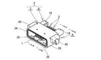
図1は本発明に係る防水機能付きコネクタの一例を示し、図中符号Aはレセプタクル、BはMicro−USBプラグ等のプラグ、CはPCB等の基板である。 FIG. 1 shows an example of a connector with a waterproof function according to the present invention, in which A is a receptacle, B is a plug such as a Micro-USB plug, and C is a substrate such as PCB.
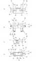
レセプタクルAは、図2〜図5に示すように、前面に開口したプラグ挿入部1を有するハウジング2と、ハウジング2に支持された複数のレセプタクル側接触端子3,3...とを備え、プラグ挿入部1内にプラグBが挿入されることにより、レセプタクル側接触端子3,3...がプラグBのプラグ側接触端子4,4...と接触し、レセプタクルAとプラグBとが電気的に接続されるようになっている。 As shown in FIGS. 2 to 5, the receptacle A includes a housing 2 having a
尚、本明細書においては、「前」はプラグ挿入部開口側をいい、「後」はプラグ挿入部奥側をいうものとする。 In this specification, “front” refers to the plug insertion portion opening side, and “rear” refers to the plug insertion portion back side.
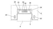
また、レセプタクルAは、所謂ミッドマウント方式により基板Cに支持され、図6に示す基板Cの前縁部に形成された切欠き部5に嵌り込み、略上半部分のみが基板上に配置されるようになっている。 Further, the receptacle A is supported on the substrate C by a so-called mid-mount method, and fits into a
ハウジング2は、筒状のシールド部材6と、絶縁性合成樹脂部材からなるモールド部材7とを一体的に成形、即ちシールド部材6を成形金型内にセットした状態でインサート成型することにより形成され、防水用被覆部8がシールド部材6の筒状外側面及び後側開口を覆うように形成され、前面にプラグBが挿入されるプラグ挿入部1が開口されている。 The housing 2 is formed by integrally molding a
シールド部材6は、図7、図8に示すように、平板状の天板部10と、天板部10の両側縁を下向きに折り曲げた形状の左右の側壁板部11,12と、左右の側壁板部11,12の下縁内側に配置された底板部13とを一体に有し、導電性金属板材を打ち抜き・曲げ加工することにより前後が開口した四角形筒状に形成され、この筒状部内はプラグBが挿入されるプラグ挿入部1を形成している。 As shown in FIGS. 7 and 8, the
尚、底板部13は、左右の側壁板部11,12の下縁より内向きに折り曲げた形状の左右の底板材13a,13bの内側端縁部を互いに突き合わせて嵌め合せることにより一枚の平板状に形成されている。また、底板部13には、係止用凹部14,14が形成されている。 The
係止用凹部14は、絞り加工により外側に凹んだ平皿状に形成され、底板部13の内外部側は非貫通状態で水滴等を通さないようになっている。尚、この係止用凹部14の外側面は防水用被覆部8の下面に露出させている。 The
また、シールド部材6には、PCB等の基板Cに接続される横向き基板接続端子部15と、後向き基板接続端子部16とを一体に備えている。 Further, the
横向き基板接続端子部15は、左右の側壁板部11,12より水平横向きに伸長した形状の横向き水平延長部17と、その横向き水平延長部17の先端側縁を下向きに折り曲げた形状の下向き端子部18とを以て構成されている。 The horizontal board
尚、横向き基板接続端子部15は、天板部10及び左右の側壁板部11,12を形成する板材の一部を横向き水平延長部の基端を残して横向き基板接続端子部15の外形に合わせて切り出し、その切り出した部分を折り曲げることにより形成されている。よって、天板部10から側壁板部11,12に渡って切り出し孔19,19が形成されている。 In addition, the horizontal board
下向き端子部18の下側側縁部には、切欠き凹部18a,18aが形成されており、下向き端子部18が基板Cに形成された挿通孔(スルーホール)20に挿入され、半田付けされた際に、半田が挿通孔20内に流れ込むと共に切欠き凹部18a内にも流れ込み、半田が固化することにより強固に固定されるようになっている。 Cutout recesses 18a, 18a are formed on the lower side edge of the
後向き基板接続端子部16は、天板部10の側部後縁より後方に延長された形状の後向き水平延長片部21と、側壁板部11,12の上部後縁より後方に延長された形状の後向き鉛直延長片部22と、後向き水平延長片部21の後縁より下向きに折り曲げた形状の下向き端子片部23とが一体に形成されている。 The rearward-facing board
後向き水平延長片部21の後縁には、切欠きを形成することにより下向き端子片部23が折り曲げやすくなっている。 By forming a notch in the rear edge of the rearward horizontal
後向き鉛直延長片部22は、後向き水平延長片部21の側縁より下向きに折り曲げた形状に形成されており、天板部10に対し側壁板部11,12が折り曲げ加工されるのに伴い後向き鉛直延長片部22も後向き水平延長片部21に対し折り曲げられている。 The rearward
また、後向き鉛直延長片部22は、その下縁部が基板Cの固定パターン24に半田付けされ、ハウジング2が基板Cに固定されるようになっている。 Further, the rearward vertical
下向き端子片部23は、下向き端子片部23が基板Cに形成された挿通孔(スルーホール)25に挿入され、半田付けされることにより半田が挿通孔25内に流れ込み、下向き端子片部23と挿通孔内面とが半田により強固に固定されるようになっている。 The downward
尚、この下向き端子片部23は、インサート成型前においては後向き水平延長片部21の後縁より水平方向に延長されており、インサート成型後下向きに折り曲げられて形成される。 The
モールド部材7は、シールド部材6の筒状外側面及び後ろ開口を覆う防水用被服部8を備え、インサート成型によりシールド部材6及びレセプタクル側接触端子3と一体化されている。 The
防水用被覆部8は、シールド部材6の後側開口を閉鎖する後壁部31と、後壁部31の周縁より前方に向けて伸長した形状の上下左右の版部32,33,34,35とを以て一体に構成され、上下左右の版部32,33,34,35はそれぞれシールド部材6の天板部10、底板部13及び左右の側壁板部11,12の外側面に密着し被覆するようになっており、後壁部31及び上下左右の版部32,33,34,35により前面のみが開口した筒状をなしている。 The
後壁部31は、矩形状に形成され、その後背面より後向き基板接続端子16,16が後方に突出した状態で露出するようになっている。 The
尚、この後壁部31に対する後向き基板接続端子突出部分の基端部にあっては、インサート成型したことにより後壁部31をなす合成樹脂部材と後向き基板接続端子部16表面とが密着した状態にあり、水の飛沫や噴流に対して保護がなされる程度、即ち水の飛沫又はノズルによる噴流水によっても有害な影響が出ない程度に水を通さないようになっている。 In addition, in the base end part of the backward board | substrate connection terminal protrusion part with respect to this
後壁部31の前面の中央下側には、前方に突出した平板状の端子支持部36が一体に形成され、シールド部材6の内側、即ちプラグ挿入部1内に突出した状態に支持されている。 A flat plate-like
この端子支持部36の上面部には、横方向に並べた配置に複数の前後方向の端子収容溝37,37...が形成されており、この端子収容溝37に沿ってレセプタクル側接触端子3の接触片部38が上面側を露出させた状態で支持されている。 A plurality of front and rear
下版部33には、シールド部材6の係止用凹部14が埋め込まれ、且つ係止用凹部14の下面が露出した状態になっており、前後方向での抜け止めの効果も担っている。 In the
尚、係止用凹部14は底板部13の板圧方向で貫通していないので、下版部33の下面と係止用凹部14の下面とを同一平面上とし、係止用凹部14を下版部の下面に露出させても、プラグ挿入部内に侵入した水滴等を通さないようになっている。 Since the locking
また、シールド部材の天板部から左右の側壁板部にかけて形成された切り出し孔19,19には、成形時に上版部及び左右版部と一体に合成樹脂材が充填され、塞がれるようになっている。 Further, the cutout holes 19 and 19 formed from the top plate portion of the shield member to the left and right side wall plate portions are filled with a synthetic resin material integrally with the upper plate portion and the left and right plate portions at the time of molding so as to be blocked. It has become.
この左右の版部34,35には、支持兼押さえ用凸部40が一体に形成され、この凸部40が基板Cの切欠き部5側縁部に支持されるようになっている。 The left and
この支持兼押さえ用凸部40は、上面及び下面が平らに形成され、上下両面が互いに平行な平面を形成するようになっている。 The supporting and pressing
また、この支持兼押さえ用凸部40は、横向き基板接続端子部15の横向き水平延長部17が内部を貫通した状態に成形され、横向き水平延長部17の強度を高める効果を奏している。 Further, the supporting and pressing
尚、支持兼押さえ用凸部40をなす合成樹脂部材と横向き水平延長部17の外面とは、密着した状態にあり、水の飛沫や噴流に対して保護がなされる程度、即ち水の飛沫又はノズルによる噴流水によっても有害な影響が出ない程度に水を通さないようになっている。 It should be noted that the synthetic resin member forming the supporting and pressing
また、図9に示すように、この支持兼押さえ用凸部40が基板対応支持手段を介して基板Cと機器躯体Dとの間に挟み込まれるようにしてもよい。 Further, as shown in FIG. 9, the supporting / pressing
基板対応支持手段は、ハウジング2の基板Cに支持される部分(支持兼押さえ用凸部40)の上側に配置され、且つ、その上面部がハウジング2の基板に支持されていない部分、即ち、切欠き部5に嵌り込んでいる部分の上面より高い位置になるように形成されている。 The substrate-corresponding support means is disposed above the portion of the housing 2 that is supported by the substrate C (supporting / pressing convex portion 40), and the upper surface portion thereof is not supported by the substrate of the housing 2, that is, It forms so that it may become a position higher than the upper surface of the part currently fitted in the
基板対応受け手段には、押え金具41を使用し、この押え金具41は、矩形状の躯体受け部42と、躯体受け部42の側縁より下向きに折り曲げた形状の鉛直ストッパー部43とを有し、金属材をもって一体に形成されている。 A holding metal fitting 41 is used as the substrate-corresponding receiving means, and this holding metal fitting 41 has a rectangular
躯体受け部42は、一定の厚さ、即ち支持兼押さえ用凸部40上に載置された際に、躯体受け部42の上面がハウジング2の上面(上版部32)より高い位置となるような厚さの平板状に形成されている。 The
鉛直ストッパー部43は、躯体受け部4の側縁より下向きに延長され、その上下方向高さは、凸部40の上下方向高さと同じ若しくはやや短く形成され、機器躯体Dに押圧された際に基板Cに当接されるようになっている。 The
このように構成されたレセプタクルAは、支持兼押さえ用凸部40が押え金具41を介して基板Cと機器躯体Dとの間に挟み込まれ、それによりハウジング2が基板Cに固定されるようになっている。 In the receptacle A configured as described above, the support / holding
このとき、ハウジング2の基板に支持されていない部分、即ち、切欠き部5に嵌り込んでいる部分は、直接機器躯体Dに直接押圧されることがなく、従ってハウジング2の基板Cに支持されていない部分の上面に分布荷重が生じず、基板Cと機器躯体Dとの間に挟み込まれた部分にのみ力が作用するので、レセプタクルAと基板Cとの間に生じるせん断力を抑え、レセプタクルA及び基板Cの撓みを抑えることができ、更に、接触端子の浮きによる半田はがれ等を防止できる。 At this time, the portion of the housing 2 that is not supported by the substrate, that is, the portion that is fitted into the
また、鉛直ストッパー部43の高さが凸部40の高さと同じ若しくはやや短く形成されていることにより、凸部40を基板Cと機器躯体Dとの間に挟み込むことができるとともに、その挟み込む力が過度に作用しないようにするストッパーの役目を担っている。 Further, since the height of the
レセプタクル側接触端子3は、長板状の接触片部38と、接触片部38の後縁より斜め上方向に折り曲げた形状の支持片部45と、支持片部45の後縁より水平方向後側に延長された後側延長片部46と、後側延長片部46の後端に一体に支持された基板接続片部47とを一体に有し、導電性板材を打ち抜き・折り曲げ加工することにより形成されている。 The receptacle-
接触片部38は、その前側端部に前方斜め下向きに折り曲げた形状の受け入れ部38aが形成されている。 The contact piece portion 38 is formed with a receiving
支持片部45は、インサート成型時にモールド部材7の後壁部31内に一体化されて埋め込まれ、レセプタクル側接触端子3,3...をモールド部材7に固定するようになっている。 The
尚、後壁部31をなす合成樹脂部材と支持片部45の外面とは、インサート成型により密着した状態にあり、水の飛沫や噴流に対して保護がなされる程度、即ち水の飛沫又はノズルによる噴流水によっても有害な影響が出ない程度に水を通さないようになっている。 The synthetic resin member forming the
基板接続片部47は、後側延長片部46の後縁より斜め下向きに折り曲げた形状の下向き片部48と、下向き片部の後縁より水平方向後側に延長された基盤接続端子49により構成され、インサート成型前においては、後側延長片部46、下向き片部48及び基板接続端子49が水平方向後方に一直線上に配置され、インサート成型後折り曲げ加工により下向き片部48を形成するようになっている。 The
尚、基板接続端子49は、基板Cの接続パターン50,50に半田付けにより接続されるようになっている。 The
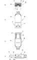
プラグBは、合成樹脂製のカバー部60の先端に突出した状態で支持された差し込み部61を有し、該差し込み部61がプラグ挿入部1内に挿入されるようになっている。 The plug B has an
差し込み部61は、図10に示すように、筒状のシールド部62と、シールド部62内に配置されたモールド部63と、モールド部63に支持された複数のプラグ側接触端子4,4...とを備え、レセプタクル側に開口した端子支持部挿入部65が形成され、プラグ挿入部内に突出した端子支持部36が挿入されるようになっている。 As shown in FIG. 10, the
モールド部63は、カバー部60の前端面より突出した断面四角形状に形成されており、その下面部に端子支持部挿入部65が形成され、端子支持部挿入部内に弾性接触部が突出するようにプラグ側接触端子4,4...が支持されている。 The
シールド部62は、導電性板材を打ち抜き折り曲げ加工することにより開口部四角形の筒状に形成され、その基端部がカバー部60に固定されている。 The
このシールド部62がモールド部63の外周を覆うことにより、支持部挿入部65の外側開口も閉鎖され、レセプタクル側のみが開口した状態になっている。 When this
また、シールド部の下面部には、係止用凹部14と互いに係合する係止用弾性片66,66が備えられている。 The lower surface of the shield part is provided with locking
この係止用弾性片66は、差し込み部61がプラグ挿入部内に挿入され、係止用凹部14の位置に到達すると自身の弾性によりプラグ部下面より外向きに突出し、係合部66bが係止用凹部14の内縁と互いに係合するようになっている。 When the
このように構成されたコネクタでは、レセプタクルAの外側部が合成樹脂部材からなる防水用被覆部8により被覆され、インサート成型によりシールド部材6、モールド部材7及び接触端子3,3...を一体的に成形したことによりシールド部材6及び接触端子3,3...の外側に露出した部分を最小限に留め、且つ露出した部分の突出基端部と合成樹脂材とが密着した状態にあり、水の飛沫や噴流に対して保護がなされる程度、即ち水の飛沫又はノズルによる噴流水によっても有害な影響が出ない程度に水を通さないようになっている。 In the connector configured as described above, the outer side of the receptacle A is covered with a
尚、上述の実施例では、所謂ミッドマウント方式による一例を示したが、ハウジング2全体が基板上に配置される所謂オンボード方式であってもよい。 In the above-described embodiment, an example of the so-called mid-mount method is shown, but a so-called on-board method in which the entire housing 2 is arranged on the substrate may be used.
また、上述の実施例では、基板接続端子部をスルーホールに通す構造としたが、表面実装するようにしたものであってもよい。この場合、リフロー炉に通す際に用いるガスケットが装着できるように、プラグ挿入部開口部にガスケット装着用の係合溝を設けておくことが望ましい。 In the above-described embodiment, the substrate connection terminal portion is configured to pass through the through hole. However, the substrate connection terminal portion may be surface-mounted. In this case, it is desirable to provide an engagement groove for mounting a gasket in the opening of the plug insertion portion so that the gasket used when passing through the reflow furnace can be mounted.
更に、シールド部材のプラグ挿入部開口部には、O−リング等の遮水部材が嵌め込まれる遮水材収容部を設けるようにしてもよい。 Furthermore, you may make it provide the water-shielding material accommodating part in which water-shielding members, such as an O-ring, are fitted in the plug insertion part opening part of a shield member.
A レセプタクル
B プラグ
C 基板
D 機器躯体
1 プラグ挿入部
2 ハウジング
3 レセプタクル側接触端子
4 プラグ側接触端子
5 切欠き部
6 シールド部材
7 モールド部材
8 防水用被覆部
10 天板部
11 左側壁板部
12 右側壁板部
13 底板部
14 係止用凹部
15 横向き基板接続端子部
16 後向き基板接続端子部
17 横向き水平延長部
18 下向き端子部
19 切り出し孔
20 挿通孔(スルーホール)
21 後向き水平延長片部
22 後向き鉛直延長片部
23 下向き端子片部
24 固定パターン
25 挿通孔(スルーホール)
31 後壁部
32 上版部
33 下版部
34 左版部
35 右版部
36 端子支持部
37 端子収容溝
38 接触片部
40 支持兼押さえ用凸部
41 押え金具
42 躯体受け部
43 鉛直ストッパー部
45 支持片部
46 後側延長片部
47 基板接続片部
48 下向き片部
49 基板接続端子
50 接続パターン
60 カバー部
61 差し込み部
62 シールド部
63 モールド部
65 端子支持部挿入部
66 係止用弾性片A Receptacle B Plug C Board
21 Backward-facing
31
Claims (3)
Translated fromJapanese該ハウジングは、基板に接続される基板接続端子部を有する筒状のシールド部材と、前記レセプタクル側接触端子を支持するモールド部材とをもって構成され、
前記プラグが前記挿入口に挿入されることにより前記プラグに支持されたプラグ側接触端子と前記レセプタクル側接触端子とが接触されるようにしてなるコネクタであって、
前記モールド部材は、前記基板接続端子部を露出させた状態で前記シールド部材の筒状外側面及び後側開口を覆う防水用被覆部を備え、インサート成型により前記シールド部材及びレセプタクル側接触端子と一体化されたことを特徴としてなる防水機能付きコネクタ。A housing in which a plug insertion portion into which a plug is inserted is opened on the front surface, and a plurality of receptacle-side contact terminals supported by the housing and exposed in the plug insertion portion;
The housing includes a cylindrical shield member having a substrate connection terminal portion connected to the substrate, and a mold member that supports the receptacle-side contact terminal,
A connector configured such that when the plug is inserted into the insertion port, the plug-side contact terminal supported by the plug and the receptacle-side contact terminal are brought into contact with each other,
The mold member includes a waterproof covering portion that covers the cylindrical outer surface and the rear opening of the shield member with the substrate connection terminal portion exposed, and is integrated with the shield member and the receptacle-side contact terminal by insert molding. A connector with a waterproof function, characterized by being
Priority Applications (2)
| Application Number | Priority Date | Filing Date | Title |
|---|---|---|---|
| JP2010198528AJP5099566B2 (en) | 2010-09-06 | 2010-09-06 | Waterproof connector |
| CN201110162004.6ACN102386518B (en) | 2010-09-06 | 2011-06-09 | Band waterproof connector |
Applications Claiming Priority (1)
| Application Number | Priority Date | Filing Date | Title |
|---|---|---|---|
| JP2010198528AJP5099566B2 (en) | 2010-09-06 | 2010-09-06 | Waterproof connector |
Publications (2)
| Publication Number | Publication Date |
|---|---|
| JP2012059381A JP2012059381A (en) | 2012-03-22 |
| JP5099566B2true JP5099566B2 (en) | 2012-12-19 |
Family
ID=45825649
Family Applications (1)
| Application Number | Title | Priority Date | Filing Date |
|---|---|---|---|
| JP2010198528AExpired - Fee RelatedJP5099566B2 (en) | 2010-09-06 | 2010-09-06 | Waterproof connector |
Country Status (2)
| Country | Link |
|---|---|
| JP (1) | JP5099566B2 (en) |
| CN (1) | CN102386518B (en) |
Cited By (1)
| Publication number | Priority date | Publication date | Assignee | Title |
|---|---|---|---|---|
| CN109326902A (en)* | 2017-08-01 | 2019-02-12 | 飞宏科技股份有限公司 | Electrical connector with adjustable mounting height and orientation |
Families Citing this family (17)
| Publication number | Priority date | Publication date | Assignee | Title |
|---|---|---|---|---|
| KR101301982B1 (en)* | 2012-07-16 | 2013-08-30 | 엘에스엠트론 주식회사 | Waterproof type receptacle connector |
| JP5696698B2 (en)* | 2012-08-23 | 2015-04-08 | Smk株式会社 | Receptacle connector |
| CN102843889B (en)* | 2012-09-10 | 2016-06-08 | 惠州Tcl移动通信有限公司 | A kind of USB water repellent component and portable electric appts |
| JP2014082102A (en)* | 2012-10-16 | 2014-05-08 | Smk Corp | Receptacle connector |
| KR101355581B1 (en) | 2012-12-14 | 2014-01-24 | 엘에스엠트론 주식회사 | Waterproof type receptacle connector |
| CN104838545B (en)* | 2012-12-28 | 2017-03-08 | 日本航空电子工业株式会社 | waterproof connector |
| CN103337735B (en)* | 2013-06-07 | 2016-06-29 | 惠州Tcl移动通信有限公司 | Mobile terminal and Micro USB connector thereof |
| JP6257182B2 (en)* | 2013-06-20 | 2018-01-10 | 株式会社エクセル電子 | Waterproof connector, electronic device, and method for manufacturing waterproof connector |
| TWI683484B (en)* | 2014-06-24 | 2020-01-21 | 捷利知產股份有限公司 | Electrical connector |
| JP5733456B1 (en)* | 2014-06-27 | 2015-06-10 | Smk株式会社 | Board connector |
| JP2016035803A (en)* | 2014-08-01 | 2016-03-17 | 南部化成株式会社 | Connector for electronic equipment having thermosetting resin waterproof member having one-layer structure |
| JP5813847B1 (en)* | 2014-10-27 | 2015-11-17 | 日本航空電子工業株式会社 | Waterproof connector |
| CN105140697B (en)* | 2015-09-23 | 2025-04-25 | 连展科技(深圳)有限公司 | Socket electrical connector |
| JP7217233B2 (en) | 2017-10-30 | 2023-02-02 | 株式会社クラレ | WATERPROOF COMPONENT, ELECTRONIC DEVICE INCLUDING THE SAME, WATERPROOF METHOD FOR INSERT MOLDED PRODUCT, AND WATERPROOF METHOD FOR ELECTRONIC DEVICE |
| CN111769410B (en)* | 2020-07-01 | 2024-05-31 | 瑞安市都邦汽车配件有限公司 | Vehicle-mounted USB charging socket |
| CN113613446B (en)* | 2021-07-01 | 2022-09-23 | 荣耀终端有限公司 | Terminal Equipment |
| CN113904186B (en)* | 2021-09-09 | 2024-05-07 | 深圳金信诺高新技术股份有限公司 | Connector, 5G communication connector and airborne electronic device |
Family Cites Families (8)
| Publication number | Priority date | Publication date | Assignee | Title |
|---|---|---|---|---|
| JPS6068483A (en)* | 1983-09-21 | 1985-04-19 | Fujitsu Ltd | character identification device |
| JPS6069483U (en)* | 1983-10-20 | 1985-05-16 | 株式会社フジクラ | Cable plug for electronic equipment wiring |
| JP2006196198A (en)* | 2005-01-11 | 2006-07-27 | Favess Co Ltd | Connector device |
| KR100642527B1 (en)* | 2005-06-24 | 2006-11-03 | 석정곤 | Manufacturing method of electric connector |
| TWM295821U (en)* | 2005-12-26 | 2006-08-11 | Hon Hai Prec Ind Co Ltd | Electrical connector |
| JP4445982B2 (en)* | 2007-06-29 | 2010-04-07 | ホシデン株式会社 | connector |
| EP2083555A3 (en)* | 2008-01-28 | 2011-09-07 | Tyco Electronics AMP Korea Limited | Waterproofing method and structure for mobile phone |
| CN201515097U (en)* | 2009-05-12 | 2010-06-23 | 昆山上正电子科技有限公司 | Structure of electronic connector |
- 2010
- 2010-09-06JPJP2010198528Apatent/JP5099566B2/ennot_activeExpired - Fee Related
- 2011
- 2011-06-09CNCN201110162004.6Apatent/CN102386518B/ennot_activeExpired - Fee Related
Cited By (2)
| Publication number | Priority date | Publication date | Assignee | Title |
|---|---|---|---|---|
| CN109326902A (en)* | 2017-08-01 | 2019-02-12 | 飞宏科技股份有限公司 | Electrical connector with adjustable mounting height and orientation |
| CN109326902B (en)* | 2017-08-01 | 2020-10-20 | 飞宏科技股份有限公司 | Electrical connector with adjustable mounting height and orientation |
Also Published As
| Publication number | Publication date |
|---|---|
| JP2012059381A (en) | 2012-03-22 |
| CN102386518B (en) | 2016-04-06 |
| CN102386518A (en) | 2012-03-21 |
Similar Documents
| Publication | Publication Date | Title |
|---|---|---|
| JP5099566B2 (en) | Waterproof connector | |
| JP6839957B2 (en) | Electrical connector and its manufacturing method | |
| JP6623022B2 (en) | Electrical connector | |
| TWI618307B (en) | Electrical receptacle connector assembly | |
| US8388380B1 (en) | Waterproof connector with board-mounted soldering plate for improved sealing | |
| JP6737011B2 (en) | Shielded connector | |
| TWM482865U (en) | Electrical connector | |
| TW201717492A (en) | Electrical connector and method of making the same | |
| JP2009290941A (en) | Electrical connection box | |
| TW201725795A (en) | Electrical connector and method of making the same | |
| KR20130083404A (en) | Waterproof electrical connector | |
| JP2020013748A (en) | Shield connector and outer conductor terminal | |
| JP2017220617A (en) | Board unit | |
| JP2012029402A (en) | Connector, electric connection box, and manufacturing method of connector | |
| TW201739122A (en) | Electrical connector and method of making the same | |
| TWI726124B (en) | Electrical connector | |
| KR100945624B1 (en) | connector | |
| JP5741335B2 (en) | Board connector | |
| JP5278269B2 (en) | Board connector | |
| US20090149078A1 (en) | Connector | |
| US7955095B1 (en) | Battery connector and contact used therein | |
| JP4589933B2 (en) | connector | |
| JP2009290943A (en) | Electrical connection box | |
| JP5472724B2 (en) | Electrical junction box | |
| JP2010055881A (en) | Perpendicular type smt connector |
Legal Events
| Date | Code | Title | Description |
|---|---|---|---|
| A977 | Report on retrieval | Free format text:JAPANESE INTERMEDIATE CODE: A971007 Effective date:20120730 | |
| TRDD | Decision of grant or rejection written | ||
| A01 | Written decision to grant a patent or to grant a registration (utility model) | Free format text:JAPANESE INTERMEDIATE CODE: A01 Effective date:20120822 | |
| A01 | Written decision to grant a patent or to grant a registration (utility model) | Free format text:JAPANESE INTERMEDIATE CODE: A01 | |
| A61 | First payment of annual fees (during grant procedure) | Free format text:JAPANESE INTERMEDIATE CODE: A61 Effective date:20120914 | |
| FPAY | Renewal fee payment (event date is renewal date of database) | Free format text:PAYMENT UNTIL: 20151005 Year of fee payment:3 | |
| R150 | Certificate of patent or registration of utility model | Ref document number:5099566 Country of ref document:JP Free format text:JAPANESE INTERMEDIATE CODE: R150 Free format text:JAPANESE INTERMEDIATE CODE: R150 | |
| LAPS | Cancellation because of no payment of annual fees |