JP5099281B1 - Extraction device - Google Patents
Extraction deviceDownload PDFInfo
- Publication number
- JP5099281B1 JP5099281B1JP2012529461AJP2012529461AJP5099281B1JP 5099281 B1JP5099281 B1JP 5099281B1JP 2012529461 AJP2012529461 AJP 2012529461AJP 2012529461 AJP2012529461 AJP 2012529461AJP 5099281 B1JP5099281 B1JP 5099281B1
- Authority
- JP
- Japan
- Prior art keywords
- seal
- cover
- connection
- take
- connection surface
- Prior art date
- Legal status (The legal status is an assumption and is not a legal conclusion. Google has not performed a legal analysis and makes no representation as to the accuracy of the status listed.)
- Active
Links
Images


Classifications
- H—ELECTRICITY
- H01—ELECTRIC ELEMENTS
- H01R—ELECTRICALLY-CONDUCTIVE CONNECTIONS; STRUCTURAL ASSOCIATIONS OF A PLURALITY OF MUTUALLY-INSULATED ELECTRICAL CONNECTING ELEMENTS; COUPLING DEVICES; CURRENT COLLECTORS
- H01R31/00—Coupling parts supported only by co-operation with counterpart
- H01R31/06—Intermediate parts for linking two coupling parts, e.g. adapter
- B—PERFORMING OPERATIONS; TRANSPORTING
- B60—VEHICLES IN GENERAL
- B60L—PROPULSION OF ELECTRICALLY-PROPELLED VEHICLES; SUPPLYING ELECTRIC POWER FOR AUXILIARY EQUIPMENT OF ELECTRICALLY-PROPELLED VEHICLES; ELECTRODYNAMIC BRAKE SYSTEMS FOR VEHICLES IN GENERAL; MAGNETIC SUSPENSION OR LEVITATION FOR VEHICLES; MONITORING OPERATING VARIABLES OF ELECTRICALLY-PROPELLED VEHICLES; ELECTRIC SAFETY DEVICES FOR ELECTRICALLY-PROPELLED VEHICLES
- B60L50/00—Electric propulsion with power supplied within the vehicle
- B60L50/10—Electric propulsion with power supplied within the vehicle using propulsion power supplied by engine-driven generators, e.g. generators driven by combustion engines
- B60L50/16—Electric propulsion with power supplied within the vehicle using propulsion power supplied by engine-driven generators, e.g. generators driven by combustion engines with provision for separate direct mechanical propulsion
- B—PERFORMING OPERATIONS; TRANSPORTING
- B60—VEHICLES IN GENERAL
- B60L—PROPULSION OF ELECTRICALLY-PROPELLED VEHICLES; SUPPLYING ELECTRIC POWER FOR AUXILIARY EQUIPMENT OF ELECTRICALLY-PROPELLED VEHICLES; ELECTRODYNAMIC BRAKE SYSTEMS FOR VEHICLES IN GENERAL; MAGNETIC SUSPENSION OR LEVITATION FOR VEHICLES; MONITORING OPERATING VARIABLES OF ELECTRICALLY-PROPELLED VEHICLES; ELECTRIC SAFETY DEVICES FOR ELECTRICALLY-PROPELLED VEHICLES
- B60L50/00—Electric propulsion with power supplied within the vehicle
- B60L50/50—Electric propulsion with power supplied within the vehicle using propulsion power supplied by batteries or fuel cells
- B60L50/60—Electric propulsion with power supplied within the vehicle using propulsion power supplied by batteries or fuel cells using power supplied by batteries
- B60L50/61—Electric propulsion with power supplied within the vehicle using propulsion power supplied by batteries or fuel cells using power supplied by batteries by batteries charged by engine-driven generators, e.g. series hybrid electric vehicles
- B—PERFORMING OPERATIONS; TRANSPORTING
- B60—VEHICLES IN GENERAL
- B60L—PROPULSION OF ELECTRICALLY-PROPELLED VEHICLES; SUPPLYING ELECTRIC POWER FOR AUXILIARY EQUIPMENT OF ELECTRICALLY-PROPELLED VEHICLES; ELECTRODYNAMIC BRAKE SYSTEMS FOR VEHICLES IN GENERAL; MAGNETIC SUSPENSION OR LEVITATION FOR VEHICLES; MONITORING OPERATING VARIABLES OF ELECTRICALLY-PROPELLED VEHICLES; ELECTRIC SAFETY DEVICES FOR ELECTRICALLY-PROPELLED VEHICLES
- B60L50/00—Electric propulsion with power supplied within the vehicle
- B60L50/50—Electric propulsion with power supplied within the vehicle using propulsion power supplied by batteries or fuel cells
- B60L50/60—Electric propulsion with power supplied within the vehicle using propulsion power supplied by batteries or fuel cells using power supplied by batteries
- B60L50/66—Arrangements of batteries
- B—PERFORMING OPERATIONS; TRANSPORTING
- B60—VEHICLES IN GENERAL
- B60L—PROPULSION OF ELECTRICALLY-PROPELLED VEHICLES; SUPPLYING ELECTRIC POWER FOR AUXILIARY EQUIPMENT OF ELECTRICALLY-PROPELLED VEHICLES; ELECTRODYNAMIC BRAKE SYSTEMS FOR VEHICLES IN GENERAL; MAGNETIC SUSPENSION OR LEVITATION FOR VEHICLES; MONITORING OPERATING VARIABLES OF ELECTRICALLY-PROPELLED VEHICLES; ELECTRIC SAFETY DEVICES FOR ELECTRICALLY-PROPELLED VEHICLES
- B60L53/00—Methods of charging batteries, specially adapted for electric vehicles; Charging stations or on-board charging equipment therefor; Exchange of energy storage elements in electric vehicles
- B60L53/10—Methods of charging batteries, specially adapted for electric vehicles; Charging stations or on-board charging equipment therefor; Exchange of energy storage elements in electric vehicles characterised by the energy transfer between the charging station and the vehicle
- B60L53/14—Conductive energy transfer
- B60L53/16—Connectors, e.g. plugs or sockets, specially adapted for charging electric vehicles
- B—PERFORMING OPERATIONS; TRANSPORTING
- B60—VEHICLES IN GENERAL
- B60L—PROPULSION OF ELECTRICALLY-PROPELLED VEHICLES; SUPPLYING ELECTRIC POWER FOR AUXILIARY EQUIPMENT OF ELECTRICALLY-PROPELLED VEHICLES; ELECTRODYNAMIC BRAKE SYSTEMS FOR VEHICLES IN GENERAL; MAGNETIC SUSPENSION OR LEVITATION FOR VEHICLES; MONITORING OPERATING VARIABLES OF ELECTRICALLY-PROPELLED VEHICLES; ELECTRIC SAFETY DEVICES FOR ELECTRICALLY-PROPELLED VEHICLES
- B60L55/00—Arrangements for supplying energy stored within a vehicle to a power network, i.e. vehicle-to-grid [V2G] arrangements
- B—PERFORMING OPERATIONS; TRANSPORTING
- B60—VEHICLES IN GENERAL
- B60L—PROPULSION OF ELECTRICALLY-PROPELLED VEHICLES; SUPPLYING ELECTRIC POWER FOR AUXILIARY EQUIPMENT OF ELECTRICALLY-PROPELLED VEHICLES; ELECTRODYNAMIC BRAKE SYSTEMS FOR VEHICLES IN GENERAL; MAGNETIC SUSPENSION OR LEVITATION FOR VEHICLES; MONITORING OPERATING VARIABLES OF ELECTRICALLY-PROPELLED VEHICLES; ELECTRIC SAFETY DEVICES FOR ELECTRICALLY-PROPELLED VEHICLES
- B60L7/00—Electrodynamic brake systems for vehicles in general
- B60L7/10—Dynamic electric regenerative braking
- B60L7/14—Dynamic electric regenerative braking for vehicles propelled by AC motors
- H—ELECTRICITY
- H01—ELECTRIC ELEMENTS
- H01R—ELECTRICALLY-CONDUCTIVE CONNECTIONS; STRUCTURAL ASSOCIATIONS OF A PLURALITY OF MUTUALLY-INSULATED ELECTRICAL CONNECTING ELEMENTS; COUPLING DEVICES; CURRENT COLLECTORS
- H01R13/00—Details of coupling devices of the kinds covered by groups H01R12/70 or H01R24/00 - H01R33/00
- H01R13/46—Bases; Cases
- H01R13/52—Dustproof, splashproof, drip-proof, waterproof, or flameproof cases
- H01R13/5205—Sealing means between cable and housing, e.g. grommet
- H—ELECTRICITY
- H01—ELECTRIC ELEMENTS
- H01R—ELECTRICALLY-CONDUCTIVE CONNECTIONS; STRUCTURAL ASSOCIATIONS OF A PLURALITY OF MUTUALLY-INSULATED ELECTRICAL CONNECTING ELEMENTS; COUPLING DEVICES; CURRENT COLLECTORS
- H01R24/00—Two-part coupling devices, or either of their cooperating parts, characterised by their overall structure
- H01R24/76—Two-part coupling devices, or either of their cooperating parts, characterised by their overall structure with sockets, clips or analogous contacts and secured to apparatus or structure, e.g. to a wall
- B—PERFORMING OPERATIONS; TRANSPORTING
- B60—VEHICLES IN GENERAL
- B60L—PROPULSION OF ELECTRICALLY-PROPELLED VEHICLES; SUPPLYING ELECTRIC POWER FOR AUXILIARY EQUIPMENT OF ELECTRICALLY-PROPELLED VEHICLES; ELECTRODYNAMIC BRAKE SYSTEMS FOR VEHICLES IN GENERAL; MAGNETIC SUSPENSION OR LEVITATION FOR VEHICLES; MONITORING OPERATING VARIABLES OF ELECTRICALLY-PROPELLED VEHICLES; ELECTRIC SAFETY DEVICES FOR ELECTRICALLY-PROPELLED VEHICLES
- B60L2210/00—Converter types
- B60L2210/30—AC to DC converters
- B—PERFORMING OPERATIONS; TRANSPORTING
- B60—VEHICLES IN GENERAL
- B60L—PROPULSION OF ELECTRICALLY-PROPELLED VEHICLES; SUPPLYING ELECTRIC POWER FOR AUXILIARY EQUIPMENT OF ELECTRICALLY-PROPELLED VEHICLES; ELECTRODYNAMIC BRAKE SYSTEMS FOR VEHICLES IN GENERAL; MAGNETIC SUSPENSION OR LEVITATION FOR VEHICLES; MONITORING OPERATING VARIABLES OF ELECTRICALLY-PROPELLED VEHICLES; ELECTRIC SAFETY DEVICES FOR ELECTRICALLY-PROPELLED VEHICLES
- B60L2210/00—Converter types
- B60L2210/40—DC to AC converters
- B—PERFORMING OPERATIONS; TRANSPORTING
- B60—VEHICLES IN GENERAL
- B60L—PROPULSION OF ELECTRICALLY-PROPELLED VEHICLES; SUPPLYING ELECTRIC POWER FOR AUXILIARY EQUIPMENT OF ELECTRICALLY-PROPELLED VEHICLES; ELECTRODYNAMIC BRAKE SYSTEMS FOR VEHICLES IN GENERAL; MAGNETIC SUSPENSION OR LEVITATION FOR VEHICLES; MONITORING OPERATING VARIABLES OF ELECTRICALLY-PROPELLED VEHICLES; ELECTRIC SAFETY DEVICES FOR ELECTRICALLY-PROPELLED VEHICLES
- B60L2220/00—Electrical machine types; Structures or applications thereof
- B60L2220/10—Electrical machine types
- B60L2220/14—Synchronous machines
- B—PERFORMING OPERATIONS; TRANSPORTING
- B60—VEHICLES IN GENERAL
- B60L—PROPULSION OF ELECTRICALLY-PROPELLED VEHICLES; SUPPLYING ELECTRIC POWER FOR AUXILIARY EQUIPMENT OF ELECTRICALLY-PROPELLED VEHICLES; ELECTRODYNAMIC BRAKE SYSTEMS FOR VEHICLES IN GENERAL; MAGNETIC SUSPENSION OR LEVITATION FOR VEHICLES; MONITORING OPERATING VARIABLES OF ELECTRICALLY-PROPELLED VEHICLES; ELECTRIC SAFETY DEVICES FOR ELECTRICALLY-PROPELLED VEHICLES
- B60L2250/00—Driver interactions
- B60L2250/16—Driver interactions by display
- B—PERFORMING OPERATIONS; TRANSPORTING
- B60—VEHICLES IN GENERAL
- B60L—PROPULSION OF ELECTRICALLY-PROPELLED VEHICLES; SUPPLYING ELECTRIC POWER FOR AUXILIARY EQUIPMENT OF ELECTRICALLY-PROPELLED VEHICLES; ELECTRODYNAMIC BRAKE SYSTEMS FOR VEHICLES IN GENERAL; MAGNETIC SUSPENSION OR LEVITATION FOR VEHICLES; MONITORING OPERATING VARIABLES OF ELECTRICALLY-PROPELLED VEHICLES; ELECTRIC SAFETY DEVICES FOR ELECTRICALLY-PROPELLED VEHICLES
- B60L2270/00—Problem solutions or means not otherwise provided for
- B60L2270/30—Preventing theft during charging
- B60L2270/32—Preventing theft during charging of electricity
- B—PERFORMING OPERATIONS; TRANSPORTING
- B60—VEHICLES IN GENERAL
- B60L—PROPULSION OF ELECTRICALLY-PROPELLED VEHICLES; SUPPLYING ELECTRIC POWER FOR AUXILIARY EQUIPMENT OF ELECTRICALLY-PROPELLED VEHICLES; ELECTRODYNAMIC BRAKE SYSTEMS FOR VEHICLES IN GENERAL; MAGNETIC SUSPENSION OR LEVITATION FOR VEHICLES; MONITORING OPERATING VARIABLES OF ELECTRICALLY-PROPELLED VEHICLES; ELECTRIC SAFETY DEVICES FOR ELECTRICALLY-PROPELLED VEHICLES
- B60L2270/00—Problem solutions or means not otherwise provided for
- B60L2270/30—Preventing theft during charging
- B60L2270/34—Preventing theft during charging of parts
- H—ELECTRICITY
- H01—ELECTRIC ELEMENTS
- H01R—ELECTRICALLY-CONDUCTIVE CONNECTIONS; STRUCTURAL ASSOCIATIONS OF A PLURALITY OF MUTUALLY-INSULATED ELECTRICAL CONNECTING ELEMENTS; COUPLING DEVICES; CURRENT COLLECTORS
- H01R2103/00—Two poles
- H—ELECTRICITY
- H01—ELECTRIC ELEMENTS
- H01R—ELECTRICALLY-CONDUCTIVE CONNECTIONS; STRUCTURAL ASSOCIATIONS OF A PLURALITY OF MUTUALLY-INSULATED ELECTRICAL CONNECTING ELEMENTS; COUPLING DEVICES; CURRENT COLLECTORS
- H01R2201/00—Connectors or connections adapted for particular applications
- H01R2201/26—Connectors or connections adapted for particular applications for vehicles
- Y—GENERAL TAGGING OF NEW TECHNOLOGICAL DEVELOPMENTS; GENERAL TAGGING OF CROSS-SECTIONAL TECHNOLOGIES SPANNING OVER SEVERAL SECTIONS OF THE IPC; TECHNICAL SUBJECTS COVERED BY FORMER USPC CROSS-REFERENCE ART COLLECTIONS [XRACs] AND DIGESTS
- Y02—TECHNOLOGIES OR APPLICATIONS FOR MITIGATION OR ADAPTATION AGAINST CLIMATE CHANGE
- Y02E—REDUCTION OF GREENHOUSE GAS [GHG] EMISSIONS, RELATED TO ENERGY GENERATION, TRANSMISSION OR DISTRIBUTION
- Y02E60/00—Enabling technologies; Technologies with a potential or indirect contribution to GHG emissions mitigation
- Y—GENERAL TAGGING OF NEW TECHNOLOGICAL DEVELOPMENTS; GENERAL TAGGING OF CROSS-SECTIONAL TECHNOLOGIES SPANNING OVER SEVERAL SECTIONS OF THE IPC; TECHNICAL SUBJECTS COVERED BY FORMER USPC CROSS-REFERENCE ART COLLECTIONS [XRACs] AND DIGESTS
- Y02—TECHNOLOGIES OR APPLICATIONS FOR MITIGATION OR ADAPTATION AGAINST CLIMATE CHANGE
- Y02T—CLIMATE CHANGE MITIGATION TECHNOLOGIES RELATED TO TRANSPORTATION
- Y02T10/00—Road transport of goods or passengers
- Y02T10/60—Other road transportation technologies with climate change mitigation effect
- Y02T10/62—Hybrid vehicles
- Y—GENERAL TAGGING OF NEW TECHNOLOGICAL DEVELOPMENTS; GENERAL TAGGING OF CROSS-SECTIONAL TECHNOLOGIES SPANNING OVER SEVERAL SECTIONS OF THE IPC; TECHNICAL SUBJECTS COVERED BY FORMER USPC CROSS-REFERENCE ART COLLECTIONS [XRACs] AND DIGESTS
- Y02—TECHNOLOGIES OR APPLICATIONS FOR MITIGATION OR ADAPTATION AGAINST CLIMATE CHANGE
- Y02T—CLIMATE CHANGE MITIGATION TECHNOLOGIES RELATED TO TRANSPORTATION
- Y02T10/00—Road transport of goods or passengers
- Y02T10/60—Other road transportation technologies with climate change mitigation effect
- Y02T10/70—Energy storage systems for electromobility, e.g. batteries
- Y—GENERAL TAGGING OF NEW TECHNOLOGICAL DEVELOPMENTS; GENERAL TAGGING OF CROSS-SECTIONAL TECHNOLOGIES SPANNING OVER SEVERAL SECTIONS OF THE IPC; TECHNICAL SUBJECTS COVERED BY FORMER USPC CROSS-REFERENCE ART COLLECTIONS [XRACs] AND DIGESTS
- Y02—TECHNOLOGIES OR APPLICATIONS FOR MITIGATION OR ADAPTATION AGAINST CLIMATE CHANGE
- Y02T—CLIMATE CHANGE MITIGATION TECHNOLOGIES RELATED TO TRANSPORTATION
- Y02T10/00—Road transport of goods or passengers
- Y02T10/60—Other road transportation technologies with climate change mitigation effect
- Y02T10/7072—Electromobility specific charging systems or methods for batteries, ultracapacitors, supercapacitors or double-layer capacitors
- Y—GENERAL TAGGING OF NEW TECHNOLOGICAL DEVELOPMENTS; GENERAL TAGGING OF CROSS-SECTIONAL TECHNOLOGIES SPANNING OVER SEVERAL SECTIONS OF THE IPC; TECHNICAL SUBJECTS COVERED BY FORMER USPC CROSS-REFERENCE ART COLLECTIONS [XRACs] AND DIGESTS
- Y02—TECHNOLOGIES OR APPLICATIONS FOR MITIGATION OR ADAPTATION AGAINST CLIMATE CHANGE
- Y02T—CLIMATE CHANGE MITIGATION TECHNOLOGIES RELATED TO TRANSPORTATION
- Y02T10/00—Road transport of goods or passengers
- Y02T10/60—Other road transportation technologies with climate change mitigation effect
- Y02T10/72—Electric energy management in electromobility
- Y—GENERAL TAGGING OF NEW TECHNOLOGICAL DEVELOPMENTS; GENERAL TAGGING OF CROSS-SECTIONAL TECHNOLOGIES SPANNING OVER SEVERAL SECTIONS OF THE IPC; TECHNICAL SUBJECTS COVERED BY FORMER USPC CROSS-REFERENCE ART COLLECTIONS [XRACs] AND DIGESTS
- Y02—TECHNOLOGIES OR APPLICATIONS FOR MITIGATION OR ADAPTATION AGAINST CLIMATE CHANGE
- Y02T—CLIMATE CHANGE MITIGATION TECHNOLOGIES RELATED TO TRANSPORTATION
- Y02T90/00—Enabling technologies or technologies with a potential or indirect contribution to GHG emissions mitigation
- Y02T90/10—Technologies relating to charging of electric vehicles
- Y02T90/12—Electric charging stations
- Y—GENERAL TAGGING OF NEW TECHNOLOGICAL DEVELOPMENTS; GENERAL TAGGING OF CROSS-SECTIONAL TECHNOLOGIES SPANNING OVER SEVERAL SECTIONS OF THE IPC; TECHNICAL SUBJECTS COVERED BY FORMER USPC CROSS-REFERENCE ART COLLECTIONS [XRACs] AND DIGESTS
- Y02—TECHNOLOGIES OR APPLICATIONS FOR MITIGATION OR ADAPTATION AGAINST CLIMATE CHANGE
- Y02T—CLIMATE CHANGE MITIGATION TECHNOLOGIES RELATED TO TRANSPORTATION
- Y02T90/00—Enabling technologies or technologies with a potential or indirect contribution to GHG emissions mitigation
- Y02T90/10—Technologies relating to charging of electric vehicles
- Y02T90/14—Plug-in electric vehicles
- Y—GENERAL TAGGING OF NEW TECHNOLOGICAL DEVELOPMENTS; GENERAL TAGGING OF CROSS-SECTIONAL TECHNOLOGIES SPANNING OVER SEVERAL SECTIONS OF THE IPC; TECHNICAL SUBJECTS COVERED BY FORMER USPC CROSS-REFERENCE ART COLLECTIONS [XRACs] AND DIGESTS
- Y02—TECHNOLOGIES OR APPLICATIONS FOR MITIGATION OR ADAPTATION AGAINST CLIMATE CHANGE
- Y02T—CLIMATE CHANGE MITIGATION TECHNOLOGIES RELATED TO TRANSPORTATION
- Y02T90/00—Enabling technologies or technologies with a potential or indirect contribution to GHG emissions mitigation
- Y02T90/10—Technologies relating to charging of electric vehicles
- Y02T90/16—Information or communication technologies improving the operation of electric vehicles
- Y—GENERAL TAGGING OF NEW TECHNOLOGICAL DEVELOPMENTS; GENERAL TAGGING OF CROSS-SECTIONAL TECHNOLOGIES SPANNING OVER SEVERAL SECTIONS OF THE IPC; TECHNICAL SUBJECTS COVERED BY FORMER USPC CROSS-REFERENCE ART COLLECTIONS [XRACs] AND DIGESTS
- Y04—INFORMATION OR COMMUNICATION TECHNOLOGIES HAVING AN IMPACT ON OTHER TECHNOLOGY AREAS
- Y04S—SYSTEMS INTEGRATING TECHNOLOGIES RELATED TO POWER NETWORK OPERATION, COMMUNICATION OR INFORMATION TECHNOLOGIES FOR IMPROVING THE ELECTRICAL POWER GENERATION, TRANSMISSION, DISTRIBUTION, MANAGEMENT OR USAGE, i.e. SMART GRIDS
- Y04S10/00—Systems supporting electrical power generation, transmission or distribution
- Y04S10/12—Monitoring or controlling equipment for energy generation units, e.g. distributed energy generation [DER] or load-side generation
- Y04S10/126—Monitoring or controlling equipment for energy generation units, e.g. distributed energy generation [DER] or load-side generation the energy generation units being or involving electric vehicles [EV] or hybrid vehicles [HEV], i.e. power aggregation of EV or HEV, vehicle to grid arrangements [V2G]
Landscapes
- Engineering & Computer Science (AREA)
- Power Engineering (AREA)
- Transportation (AREA)
- Mechanical Engineering (AREA)
- Life Sciences & Earth Sciences (AREA)
- Sustainable Development (AREA)
- Sustainable Energy (AREA)
- Electric Propulsion And Braking For Vehicles (AREA)
- Connector Housings Or Holding Contact Members (AREA)
- Charge And Discharge Circuits For Batteries Or The Like (AREA)
- Secondary Cells (AREA)
Abstract
Translated fromJapaneseDescription
Translated fromJapanese本発明は、取出装置に関する。 The present invention relates to a take-out device.
バッテリ等の蓄電装置から電力供給を受けて走行用動力を出力するモータを動力源として備える電気自動車やハイブリッド自動車等の電動車両がある。このような電動車両のうち、車両が自宅等で駐車されている間に蓄電装置の充電を可能にするために、電力コードを介して外部電源に接続される充電コネクタを接続する充電口を備えたものが知られている。たとえば、特開2010−165596号公報に記載された車両は、充電ステーションなどに設けられた充電コネクタが接続される充電口と、バッテリとを備える。 There are electric vehicles such as an electric vehicle and a hybrid vehicle that include, as a power source, a motor that receives power supply from a power storage device such as a battery and outputs driving power. Among such electric vehicles, in order to allow charging of the power storage device while the vehicle is parked at home or the like, a charging port for connecting a charging connector connected to an external power source through a power cord is provided. Is known. For example, a vehicle described in JP 2010-165596 A includes a charging port to which a charging connector provided at a charging station or the like is connected, and a battery.
近年、車両に搭載されたバッテリの電力を家などの建物に給電するシステムについても着目されている。 In recent years, attention has also been paid to a system for supplying power from a battery mounted on a vehicle to a building such as a house.
たとえば、特開2009−278776号公報に記載された車両は、車載バッテリと、電力取り出し用の電力出力端子が設けられている。電力出力端子と建物側の電力入力端子とは、接続電力線を介して接続されるようになっている。具体的には、接続電力線の両端には一対の接続プラグが設けられており、これらを電力入力端子及び電力出力端子にそれぞれ差し込むことにより両端子は接続される。これにより、自動車の車載バッテリに蓄電された電力が接続電力線を介して建物側に供給される。 For example, a vehicle described in Japanese Patent Application Laid-Open No. 2009-278776 is provided with an in-vehicle battery and a power output terminal for extracting power. The power output terminal and the power input terminal on the building side are connected via a connection power line. Specifically, a pair of connection plugs are provided at both ends of the connection power line, and both terminals are connected by inserting them into a power input terminal and a power output terminal, respectively. Thereby, the electric power stored in the in-vehicle battery of the automobile is supplied to the building side via the connection power line.
また、特開2010−55836号公報には、建物側に設けられたコンセント装置の具体的な構成について提案されている。 Japanese Unexamined Patent Application Publication No. 2010-55836 proposes a specific configuration of an outlet device provided on the building side.
しかし、上記従来の特許文献においては、バッテリと、バッテリに電力を供給する供給する充電プラグが接続される充電接続部を備えた車両の充電接続部に接続され、バッテリに蓄電された電力を外部に取り出すための取出装置の具体的な構成を提案するものはない。 However, in the above-mentioned conventional patent document, the battery and the charging connection part of the vehicle provided with the charging plug for supplying power to the battery are connected, and the electric power stored in the battery is externally connected. There is no suggestion of a specific configuration of the take-out device for taking out.
その一方で、車両の充電接続部に接続される取出装置は、車両外部の環境を考慮する必要もあり、各種の構成上の工夫を施す必要がある。 On the other hand, the take-out device connected to the charging connection portion of the vehicle needs to consider the environment outside the vehicle, and needs to be devised in various ways.
本発明は、上記のような課題に鑑みてなされたものであって、その目的は、車両外部の各種の環境を考慮した取出装置を提供することである。 This invention is made | formed in view of the above subjects, The objective is to provide the taking-out apparatus which considered various environments outside a vehicle.
本発明に係る取出装置は、蓄電器と第1接続部とを備えた車両の第1接続部に接続されることによって、蓄電器に蓄積された電力を外部に放電することが可能な取出装置である。車両の周面に設けられた第1接続部に接続される第2接続部と、外部機器の電気プラグが接続可能な第3接続部とを備える。上記第3接続部は、電気プラグの端子が挿入される端子穴が形成された接続面を含む。上記接続面は、取出装置が第1接続部に接続された状態で、端子穴が下を向くように垂直方向に対して傾斜する。好ましくは、上記第2接続部は、車両の側面に設けられた第1接続部に接続される。好ましくは、上記接続面の少なくとも一部と、第2接続部の少なくとも一部とは、取出装置が第1接続部に接続された状態において、互いに水平方向に重なり合う。Take-out apparatus according to the present invention,by Rukoto is connected to the first connecting portion of a vehicle equipped with a condenserand a first connecting portion, it iscapable of take-out apparatusthat discharges thepower stored in the electric storage packto the outside . A second connection portion connected to a first connection portion provided on aperipheral surface of the vehicle, and a third connection portion to whichan electric plug of anexternal device can be connected. The third connection part includesa connection surface in which a terminal hole into which a terminal of theelectric plug is inserted is formed. The connection surface isinclined with respect to the vertical direction so that theterminal hole faces downward in a state where the take-out device is connected to the first connection portion. Preferably, the second connection portion is connected to a first connection portion provided on a side surface of the vehicle. Preferably, at least a part of the connection surface and at least a part of the second connection part overlap each other in the horizontal direction in a state where the take-out device is connected to the first connection part.
好ましくは、上記第1接続部は、充電プラグが接続され、蓄電器に電力を供給することが可能である外部電源から供給された電力によって蓄電器が充電される。Preferably,the first connecting portion is connected to a charging plug, and the capacitor is charged by electric power supplied from an external power source capable of supplying electric power to the capacitor .
好ましくは、上記接続面から外部に向けて延びる接続面の法線は、水平方向に対して下向きに傾斜する。Preferably,the normal line of the connection surface extending outward from the connection surface is inclined downward with respect to the horizontal direction.
好ましくは、上記電気プラグは、外部機器と取出装置とを接続する外部接続プラグである。Preferably, theelectrical plug is an external connection plug for connecting an external device and the take-out device.
好ましくは、上記取出装置に固定されることで接続面が覆われるカバーをさらに備える。Preferably,a cover that covers the connection surface by being fixed to the take-out device is further provided.
好ましくは、上記カバーが取出装置に固定されていない状態において、電気プラグを挿入するための開口部が形成される。Preferably,an opening for inserting the electric plug is formed in a state where the cover is not fixed to the take-out device.
好ましくは、上記カバーが取出装置に固定された状態において、カバーと取出装置とによって、電気プラグのコードが引き出される引出孔が形成される。Preferably,in the state where the cover is fixed to the take-out device, a lead-out hole through which the cord of the electric plug is drawn is formed by the cover and the take-out device.
好ましくは、上記カバーが取出装置に固定された状態におけるカバーの底面に孔が形成される。Preferably, a hole is formed in the bottom surface of the cover in a state where the cover is fixed to the take-out device .
好ましくは、上記接続面の上方に庇状に形成された突出部をさらに備える。Preferably,it further includes a protrusion formed in a hook shape above theconnection surface.
好ましくは、上記カバーは、接続面よりも下方に位置する軸部を中心として回転可能に設けられる。Preferably, the cover is provided so as to be rotatable about a shaft portion positioned below the connection surface.
好ましくは、上記カバーは、取出装置と係合する係合部を含む。好ましくは、上記カバーが取出装置に固定された状態において、接続面に接続された電気プラグのコードを挟み込むシールをさらに備える。Preferably, thecover includes an engaging portion that engages with the take-out device. Preferably, the apparatus further includes a seal that sandwiches the cord of the electric plug connected to the connection surface in a state where the cover is fixed to the take-out device.
本発明に係る取出装置によれば、各種の環境下においても、良好に使用することができる取出装置を提供することである。 According to the take-out device of the present invention, it is an object to provide a take-out device that can be used satisfactorily even in various environments.
図1から図49を用いて、本発明の実施の形態に係るケーブル収容装置および車両について説明する。下記の実施の形態においては、所謂ハイブリッド車両に適用した例について説明するが、電気自動車にも適用することができるのはいうまでもない。 A cable housing device and a vehicle according to an embodiment of the present invention will be described with reference to FIGS. In the following embodiment, an example applied to a so-called hybrid vehicle will be described, but it goes without saying that the embodiment can also be applied to an electric vehicle.
(実施の形態1)
図1は、車両10を示す左側斜視図であり、図2は、図1に示す車両10の右側斜視図である。(Embodiment 1)
FIG. 1 is a left perspective view showing the
図1において、車両10は、車両10の外郭を形成するボディ11と、ボディ11内に収容された燃料タンクFTおよびバッテリBとを備える。 In FIG. 1, a
ボディ11の表面は、上面12と、下面13と、周面14とを含み、周面14は、側面15および側面16と、前面17と、背面18とを含む。 The surface of the
図1および図2において、側面15には、乗降用開口部22が形成されており、ボディ11は、乗降用開口部22を開閉するドア23およびドア24を含む。なお、この図1および図2に示す例においては、運転席は、側面15よりも側面16側に配置されており、運転席には、車両10を操作するハンドルなどの操作部が設けられている。 In FIG. 1 and FIG. 2, a
側面15には、給油部20および充電部21が設けられており、給油部20は、周面14に設けられると共に、乗降用開口部22より後方側に配置されている。充電部21は、側面16に設けられると共に乗降用開口部22より後方側に配置されている。なお、充電部21の搭載位置としては、側面15に限られない。たとえば、車両10の正面や背面や上面などに設けることができる。なお、上面としては、エンジンルーフなどが挙げられる。 The
給油部20は、外部に設けられた給油ノズルのノズル部が挿入されるノズル挿入部20aと、ボディ11に設けられた蓋部20bとを備える。蓋部20bが開けられることで、ノズル挿入部20aの開口部が外部に露出し、ノズル挿入部20aに給油ノズルのノズルを挿入可能となる。 The
ノズル挿入部20aは、燃料タンクFTに接続されており、ノズル挿入部20aから供給された燃料は、燃料タンクFTに供給される。なお、内燃機関を備えた車両においては、供給される燃料としては、ガソリン、LPガス(Liquefied petroleum gas)などが挙げられる。さらに、燃料電池を備えた車両においては、液体水素やエタノールなどが挙げられる。 The
充電部21は、外部に設けられた充電プラグ93が装着される充電コネクタ21aと、ボディ11に設けられた蓋部21bとを含む。蓋部21bが開けられることで、充電コネクタ21aが外部に露出し、充電プラグ93を充電コネクタ21aに装着可能となっている。 The charging
充電コネクタ21aから供給された電力は、充電コネクタ21aや変換器などを介して、バッテリBに供給される。 The electric power supplied from the charging
図2において、側面16には、乗降用開口部25が形成されており、ボディ11は乗降用開口部25を開閉するドア26およびドア27が設けられている。 In FIG. 2, a
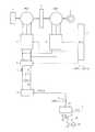
図3は、車両10を示すブロック図である。車両10は、エンジン1と、モータジェネレータMG1,MG2と、動力分割機構2と、バッテリBと、コンデンサCと、リアクトルLと、コンバータ4と、インバータ5およびインバータ6と、車両ECU(Electronic Control Unit)7と、リレーなどのスイッチング素子8と、変換器9と、充電部21とを備える。 FIG. 3 is a block diagram showing the
動力分割機構2は、エンジン1およびモータジェネレータMG1,MG2に結合されており、これらの間で動力を分配する。たとえば、動力分割機構2としては、サンギヤ、プラネタリキャリヤおよびリングギヤの3つの回転軸を有する遊星歯車機構が用いられる。この3つの回転軸は、エンジン1、モータジェネレータMG1,MG2の各回転軸に接続されている。たとえば、モータジェネレータMG1のロータを中空とし、その中心にエンジン1のクランク軸を通すことによって、動力分割機構2にエンジン1およびモータジェネレータMG1,MG2を機械的に接続されている。 Power split
なお、モータジェネレータMG2の回転軸は、図示しない減速ギヤや差動ギヤによって駆動輪である前輪3に結合されている。動力分割機構2の内部には、モータジェネレータMG2の回転軸に対する減速機がさらに組み込まれてもよい。 The rotating shaft of motor generator MG2 is coupled to
モータジェネレータMG1は、エンジン1によって駆動される発電機として動作し、かつ、エンジン1の始動を行ない得る電動機として動作するものとして車両10に組み込まれている。モータジェネレータMG2は、車両10の駆動輪である前輪3を駆動する電動機として車両10に組み込まれている。 Motor generator MG1 is incorporated in
モータジェネレータMG1,MG2は、たとえば、三相交流同期電動機である。モータジェネレータMG1,MG2は、U相コイル、V相コイル、W相コイルからなる三相コイルをステータコイルとして含む。 Motor generators MG1 and MG2 are, for example, three-phase AC synchronous motors. Motor generators MG1 and MG2 include a three-phase coil including a U-phase coil, a V-phase coil, and a W-phase coil as a stator coil.
モータジェネレータMG1は、エンジン出力を用いて三相交流電圧を発生し、その発生した三相交流電圧をインバータ5へ出力する。モータジェネレータMG1は、インバータ5から受ける三相交流電圧によって駆動力を発生し、エンジン1の始動を行なう。 Motor generator MG1 generates a three-phase AC voltage using the engine output, and outputs the generated three-phase AC voltage to
モータジェネレータMG2は、インバータ6から受ける三相交流電圧によって車両の駆動トルクを発生する。モータジェネレータMG2は、車両の回生制動時、三相交流電圧を発生してインバータ6へ出力する。 Motor generator MG <b> 2 generates vehicle driving torque by the three-phase AC voltage received from
スイッチング素子8は充電部21と変換器9との間に配置されている。スイッチング素子8は、充電部21と変換器9とを接続したり、充電部21と変換器9との接続を切断したりする。変換器9は、車両ECU7のコントロール信号CNTL2によって駆動が制御されている。スイッチング素子8は、車両ECU7のコントロール信号CNTL2によってON/OFFが切り替えられる。 The switching
充電プラグ93を充電部21の充電コネクタ21aに接続して、バッテリBを充電するときには、車両ECU7は、スイッチング素子8をONにして、充電部21と変換器9とを接続する。そして、車両ECU7は、外部電源91から供給された交流電力を直流電力に変換するように、変換器9を駆動する。 When the battery plug B is charged by connecting the charging
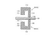
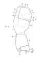
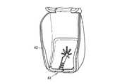
図4は、電力取出機器30を示す側面図である。この電力取出機器30は、図2に示す充電部21に接続され、バッテリBに蓄電された電力を取り出すための機器である。この電力取出機器30には、炊飯器など機器の電気プラグを接続することが可能であり、バッテリBからの電力で当該炊飯器などの電気機器を駆動することができる。 FIG. 4 is a side view showing the
図4において、電力取出機器30は、柱状に形成された本体部33と、この本体部33に接続された本体部34とを備える。本体部33は、本体部33の一端に設けられ、車両10の充電部21に接続される接続部31と、充電部21に形成された凹部に引っ掛けられる爪部35と、爪部35と充電部21との係合状態を解除するスイッチ36とを含む。 In FIG. 4, the
接続部31は、充電部21に設けられた端子部に接続される端子部37と、充電部21の周囲に設けられた環状の溝部に嵌る筒部38とを含む。 The
本体部34の一方の端部は、本体部33の他端に接続されている。本体部34は、本体部34の他方の端部に設けられ、外部の電気機器の電気プラグなどが接続される接続部32を含む。 One end of the
接続部32は、本体部34の端部に形成された端面39と、この端面39に形成され、電気プラグが接続される接続面40と、この接続面40の上方に設けられた突出部41と、接続面40よりも下方に位置する部分で回転可能に支持されたカバー42と、シール43と、環状壁部44とを含む。 The
そして、接続面40を接続面40から離れた位置から接続面40に垂直な方向に投影することで形成される投影領域Rは、接続部31が設けられた本体部33の端部を通る。 A projection region R formed by projecting the
接続面40の少なくとも一部と、接続部31の少なくとも一部とは、電力取出機器30を充電部21に接続した状態において、互いに水平方向に重なり合うように形成されている。 At least a part of the
接続面40には、接続される電気プラグの端子が挿入される端子穴が形成されている。ここで、電力取出機器30が車両10の充電部21に接続された状態において、接続面40に沿って延びる仮想平面を仮想平面45とする。 The
電力取出機器30が充電部21に接続された状態において、接続面40をとおり仮想平面45に垂直な直線を仮想直線46とする。電力取出機器30が21に接続された状態において、接続面40をとおり水平方向に延びる仮想直線を仮想直線47とする。仮想直線46は接続面40から離れるにつれて、仮想直線47よりも下方に向けて延びる。このように、接続面40は、傾斜するように配置されている。上記のように、仮想直線47は、水平方向に延びる仮想線であり、電力取出機器30の接続姿勢に関係なく、水平方向に延びる仮想線である。 In a state where the
たとえば、雨天の状態で屋外で、電力取出機器30を使用する場合においても、上記のように接続面40は傾斜するように配置されているため、雨水などが接続面40に付着することを抑制することができる。 For example, even when the power take-out
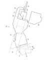
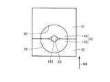
図5は、接続部32を示す斜視図である。この図5に示すように、突出部41は庇状に形成されている。突出部41は、上壁部50と、上壁部50の先端部から下方に向けて延びる垂下部51とを含む。上壁部50には、窓部54が形成されており、使用者は、上方から接続面40を視認することができる。なお、垂下部51には、係合溝が形成されている。 FIG. 5 is a perspective view showing the
カバー42は、本体部34に形成された軸部56に回転可能に設けられている。軸部56は、接続面40よりも下方に形成されている。カバー42は、垂下部51に形成された係合溝と係合する係合部53を含み、カバー42が突出部41と係合することで、接続面40は、突出部41とカバー42とによって覆われる。これにより、雨水などの異物が接続面40に付着することを抑制することができる。 The
カバー42の縁部には凹部55が形成され、カバー42には、水抜孔58が形成されている。カバー42が突出部41と係合すると、凹部55と突出部41とによって電気プラグのコードを引き出すことができる引出孔57が形成される。 A
水抜孔58は、カバー42の底部に形成されており、カバー42内に入り込んだ水などの異物を外部に排出するための孔である。ここで、図4において、接続面40は、水抜孔58から水抜孔58の延びる方向に延びる仮想直線を仮想直線59とすると、接続面40は、仮想直線59から離れた位置に設けられている。すなわち、仮想直線59が接続面40を通らないように水抜孔58が形成されている。 The
図4に示すように、カバー42を閉じた状態において、飛散した雨水などが水抜孔58をとおってカバー42内に入り込んだとしても、当該雨水などの異物が接続面40に付着することを抑制することができる。 As shown in FIG. 4, in the state where the
図5において、シール43は、垂下部51の下端面に設けられたシール60と、カバー42に設けられたシール61と、カバー42に設けられたシール62とを含む。シール60は、長尺に形成されている。なお、柱状に形成されたシール60内に空隙を形成するようにしてもよい。 In FIG. 5, the
シール61は、カバー42の内側に設けられており、凹部55と隣り合う位置に設けられている。 The
シール62は、シール61に対して凹部55と反対側に設けられている。このため、カバー42が突出部41に係合した状態において、シール61は、引出孔57に対して接続面40側に隣り合うように設けられている。カバー42が突出部41に係合した状態において、シール62は、シール61よりも接続面40側に位置している。 The
カバー42と突出部41とが係合した状態において、シール62とシール60とが接触する。 In a state where the
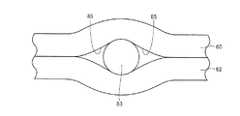
図6は、カバー42と突出部41とが互いに係合した状態におけるシール43を示す斜視図である。この図6に示すように、カバー42と突出部41とが互いに係合することで、シール60とシール62とが接触する。 FIG. 6 is a perspective view showing the
シール61には、スリット部65が形成されており、このスリット部65によって、シール61は、シール片63およびシール片64に分割されている。 A
スリット部65は、カバー42の開閉方向66に延びるスリット部67と、シール片63に形成されたスリット部68と、シール片64に形成されたスリット部69とを含む。 The
スリット部68は、スリット部67の縁部から開閉方向66と交差する方向に延びるように形成されている。なお、シール片63には、複数のスリット部68が開閉方向66に間隔をあけて形成されている。これにより、シール片63のスリット部67の縁部には、開閉方向66に間隔をあけて複数の片部70が形成されている。 The
スリット部69は、スリット部67の縁部から開閉方向66の交差する方向に延びるように形成されている。なお、シール片64には、複数のスリット部69が開閉方向66に間隔をあけて形成されている。これにより、シール片64のスリット部67の縁部には、開閉方向66に間隔をあけて複数の片部71が形成されている。 The
図7は、突出部41およびカバー42を省略した接続部32を示す斜視図である。この図7に示すように、環状壁部44は、接続面40の上方に設けられ、外方に向けて突出する天板部75と、接続面40から側方に離れた位置から上方に向けて延びる側壁部76および側壁部77と、枠部78,79,80とを含む。 FIG. 7 is a perspective view showing the connecting
側壁部76は、天板部75の一方の端部から下方に向けて垂れ下がるように形成され、側壁部77は、天板部75の他方の端部から下方に向けて垂れ下がるように形成されている。側壁部76,77の高さ(端面39からの高さ)は、接続面40の側方から天板部75に向かうにつれて、高くなるように形成されている。 The
枠部78は、側壁部76の下端部から下方に向けて延びるように形成されている。枠部79も、側壁部77の下端部から下方に向けて延びるように形成されている。枠部80は、端面39の下辺部に沿って延びるように形成されており、枠部80は、枠部78の下端部と枠部79の下端部とを接続する。 The
このように、環状壁部44が環状に形成されているため、雨天などの環境の下、電力取出機器30を使用したとしても、接続面40に雨水などの異物が付着することを抑制することができる。 As described above, since the
さらに、高さの高い側壁部76および側壁部77が設けられているため、斜め方向から雨などが吹き付けられたとしても、接続面40に雨水などの異物が付着することを抑制することができる。 Furthermore, since the
図8は、接続部32の下端部付近を模式的に示す側面図である。この図8に示すように、カバー42を閉じた状態においても、本体部34の下端部と、カバー42との間には、僅かな隙間が形成される。その一方で、枠部80が端面39の下辺部に沿って設けられているため、仮に、雨水などの異物が入り込んだとしても、図7に示す接続面40に当該雨水が付着することを抑制することができる。 FIG. 8 is a side view schematically showing the vicinity of the lower end portion of the
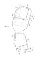
図9は、カバー42と突出部41との係合状態を解除して、カバー42を開いた状態を示す電力取出機器30の側面図である。この図9に示すように、カバー42を開くことで、電気プラグを挿入するための開口部81が形成される。 FIG. 9 is a side view of the
このように構成された電力取出機器30の使用方法について説明する。
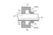
図10は、電力取出機器30を車両10の充電部21に接続した状態を示す電力取出機器30の側面図である。この図10において、接続部31を充電部21に接続する。その後、カバー42をあけて、電気プラグ82を接続面40に接続する。The usage method of the electric
FIG. 10 is a side view of the power take-out
電気プラグ82を接続面40に接続する際には、使用者は、接続面40に垂直な方向に向けて押圧力を加える。電力取出機器30に加えられた押圧力は、本体部33の端部と車両10との接続部位によって支持される。 When connecting the
ここで、接続面40から離れた位置から接続面40に垂直な方向に接続面40を投影した領域を投影領域R1とする。投影領域R1は、接続部31が設けられた本体部33の端部を通る。図11は、本体部33の端部と、投影領域R1との位置関係を模式的に示す模式図である。この図11に示すように、投影領域Rと、本体部33の端部とは互いに重なり合う。 Here, a region where the
このため、使用者から加えられた押圧力によって、電力取出機器30の端部と、車両10との接続部位に加えられる回転モーメントが低減されている。これにより、電力取出機器30の先端部や車両10の充電部21などが損傷することを抑制することができる。 For this reason, the rotational moment applied to the connection part of the edge part of the electric
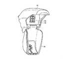
図12は、電気プラグ82を接続面40に接続したときの様子を示す接続部32およびその周囲を示す斜視図である。この図12に示すように、突出部41の上壁部50には、窓部54が形成されている。このため、電気プラグ82を装着する際に、使用者は、接続面40および電気プラグ82を視認しながら電気プラグ82を接続面40に装着することができる。 FIG. 12 is a perspective view showing the
図13は、図12に示す状態からカバー42を閉じた状態を示す斜視図である。この図13に示すように、カバー42を閉方向84に回転させて、係合部53を突出部41に形成された係合溝52に引っ掛ける。これにより、カバー42が垂下部51に固定される。 FIG. 13 is a perspective view showing a state in which the
カバー42を垂下部51に固定すると、図12に示す電気プラグ82および接続面40は、カバー42および突出部41によって覆われ、雨水などの異物がカバー42内に入り込むことを抑制することができる。コード83は、引出孔57から外部に引き出される。 When the
図14は、図13に示すように、カバー42を突出部41に固定した状態におけるシール60,61,63およびコード83を示す斜視図である。この図14に示すように、カバー42を閉方向84に回転させると、カバー42に設けられたシール61およびシール62も、閉方向84に変位する。そして、シール62の一部がシール60と接触すると共に、コード83がシール60およびシール62によって挟み込まれる。また、コード83は、スリット部67からシール61内に入り込む。 FIG. 14 is a perspective view showing the
図15は、図14に示すシール60、シール62およびコード83を示す正面図である。この図15に示すように、シール60とシール61とがコード83を挟み込むことで、コード83の横側には、コード83とシール60とシール62とによって隙間85が形成される。 FIG. 15 is a front view showing the
図14に示すように、シール61のシール片63には、複数の片部70が形成され、シール61にも複数の片部71が形成されている。コード83がスリット部67内に入り込むと、片部70および片部71は、コード83によって押し広げられ、片部70,71は、コード83に接触する。 As shown in FIG. 14, a plurality of
このため、コード83の横側に形成された隙間85は、コード83の横側に位置する複数の片部70,71によって覆われる。 For this reason, the
この結果、図13に示すように、カバー42を垂下部51に固定した状態において、引出孔57から雨水などの異物がカバー42内に入り込むことを抑制することができる。 As a result, as shown in FIG. 13, foreign matters such as rainwater can be prevented from entering the
このように、本実施の形態1に係る電力取出機器30によれば、電力取出機器30を使用する際に、雨水などの異物がカバー42内に入り込むことを抑制することができる。 As described above, according to the
また、仮に、カバー42内に雨水などが入り込んだとしても、図4に示す水抜孔58から当該雨水などの異物を外部に排出することができる。なお、本実施の形態1に係る車両10においては、バッテリBに電力を受電するための充電部21に電力取出機器30を接続する例について説明したがこれに限られない。たとえば、バッテリBに蓄電された電力を外部に放電する放電部として機能を有していてもよい。このため、充電部21は、バッテリBに電力を充電する機能と、バッテリBに蓄積された電力を外部に放電する機能との少なくとも一方を備える接続部である。
(実施の形態2)
図16から図33を用いて、本実施の形態2に係る電力取出機器30について説明する。なお、図16から図33に示す構成のうち、上記図1から図15に示す構成と同一または相当する構成については、同一の符号を付してその説明を省略する場合がある。Further, even if rainwater or the like enters the
(Embodiment 2)
The
図16は、実施の形態2に係る電力取出機器30を示す側面図である。この図16に示すように、電力取出機器30は、カバー42内から引き出される電気プラグのコードをシールするシール95を備える。 FIG. 16 is a side view showing
シール95は、垂下部51に設けられたシール88と、カバー42の上辺部に設けられたシール89とを含む。 The
図17は、シール88,89およびその周囲の構成を示す斜視図である。この図17に示すように、カバー42の上辺部には、凹部55が形成されている。同様に、垂下部51の下端部にも、凹部90が形成されている。シール89は、凹部55内に嵌め込まれており、シール88は、凹部90内に嵌め込まれている。 FIG. 17 is a perspective view showing the configurations of the
図18は、カバー42を垂下部51に固定した状態におけるシール88およびシール89を示す断面図である。 FIG. 18 is a cross-sectional view showing the
図17および図18に示すように、シール89は、半円状に形成されたシール片100と、このシール片100よりも接続面40側に位置する半円状のシール片101と、シール片100の外周縁部とシール片101の外周縁部とを接続する周壁部102とを含む。 As shown in FIGS. 17 and 18, the
シール片100とシール片101とは互いに間隔をあけて配置されている。シール片100の上面には、溝部103が形成され、シール片101の上面にも、溝部104が形成されている。 The
そして、シール片100とシール片101との間には、シール片100とシール片101と周壁部102とによって形成された隙間部105が形成されている。 A
シール88は、半円状に形成されたシール片110と、シール片110よりも接続面40側に配置された半円状のシール片111と、シール片110の周縁部とシール片111の周縁部とを接続する空隙部115とを含む。 The
シール片110の下辺部には、溝部113が形成されている。シール片111の下辺部にも、溝部114が形成されている。シール片110とシール片111とは、互いに間隔をあけて配置されており、シール片110とシール片111と周壁部112によって、空隙部115が形成されている。 A
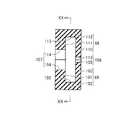
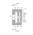
図19は、図18に示す状態のシール88およびシール89を示す正面図である。この図19および図18に示すようにカバー42が突出部41に固定されることで、シール片100の上面と、シール片111の下面とが接触すると共に、溝部103と溝部113とによって、コードが引き出される挿入孔106が形成される。この挿入孔106は、長方形形状に形成されており、横長に形成されている。 FIG. 19 is a front view showing the
図20は、図18に示すXX−XX線における断面図である。この図20に示すように、カバー42が突出部41に固定されることで、シール片101の上面と、シール片111の下面とが接触する。そして、シール片101に形成された溝部104と、シール片111に形成された溝部114とによってコードが引き出される挿入孔107が形成される。挿入孔107は円形形状に形成されている。 20 is a cross-sectional view taken along line XX-XX shown in FIG. As shown in FIG. 20, the
ここで、図19および図20において、挿入孔107の開口面積は、挿入孔106の開口面積よりも大きい。 Here, in FIG. 19 and FIG. 20, the opening area of the
図21は、径の小さいコード83を引き出した状態を示すシール95の断面図であり、図22は、径の大きいコード83を引き出した状態を示すシール95の断面図である。図21において、径の小さいは、シール片110とシール片100とによって挟み込まれると共に、挿入孔106から外部に引き出される。このため、シール片110とシール片100とによって、カバー42内に雨水などの異物が入り込むことを抑制することができる。 FIG. 21 is a cross-sectional view of the
また、仮に、雨水などの異物がコード83と、シール片100と、シール片110との間からシール95内に入り込んだとしても、シール89,88には、隙間部105,115と、シール片101,111が形成されているため、当該異物がカバー42内に入り込むことを抑制することができる。 Even if foreign matter such as rainwater enters the
図22において、径の大きいコード83は、挿入孔107に挿入されると共に、コード83は、シール片111とシール片101とによって挟み込まれる。これにより、雨水などの異物がカバー42内に入り込むことを抑制することができる。シール片100とシール片110とは、コード83によって湾曲するように変形する一方で、外部から雨水が入り込むことを抑制する。 In FIG. 22, a
また、シール片101,111と、シール片100,110との間には、隙間部105,115が形成されているため、シール片100,110を乗り越えた雨水などが、カバー42内に入り込むことを抑制することができる。 In addition, since
図23から図28を用いて、シールの第1変形例について説明する。
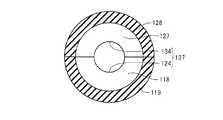
図23は、第1変形例に係るシール95を示す断面図である。この図23に示すように、シール89は、シール片116と、このシール片116に対して接続面40側に配置されたシール片117と、このシール片117に対して接続面40側に配置されたシール片118と、周壁部119とを含む。A first modification of the seal will be described with reference to FIGS.
FIG. 23 is a cross-sectional view showing a
シール片116,117,118は、半円状に形成されている。そして、周壁部119は、シール片116の外周縁部と、シール片117の外周縁部と、シール片118の外周縁部とを接続する。シール片116と、シール片117との間には、空隙部120が形成され、シール片117とシール片118との間には、空隙部121が形成されている。 The
シール88は、シール片125と、シール片125よりも接続面40側に配置されたシール片126と、シール片126よりも接続面40側に配置されたシール片127と、周壁部128とを含む。 The
周壁部128は、シール片125の外周縁部と、シール片126の外周縁部と、シール片127の外周縁部とを接続するように形成されている。シール片125と、シール片126との間には、空隙部130が形成されており、シール片126とシール片127との間には、空隙部131が形成されている。 The
図24は、シール95の正面図であり、カバー42が突出部41に固定された状態におけるシール95の正面図である。この図24に示すように、シール片116は、半円状に形成されており、シール片116の上面には、溝部122が形成されている。 FIG. 24 is a front view of the
シール片125も、半円状に形成されており、シール片125の下面には、溝部132が形成されている。 The
カバー42が突出部41に固定されている場合には、シール片125の下面と、シール片116の上面とが接触する。そして、溝部122と溝部132とによってコードが引き出される挿入孔135が形成される。 When the
図25は、図23に示すXXV−XXV線における断面図である。この図25に示すように、シール片117は半円状に形成されており、シール片117の上面には、溝部123が形成されている。シール片126も半円状に形成されており、シール片126の下面には、溝部133が形成されている。 25 is a cross-sectional view taken along line XXV-XXV shown in FIG. As shown in FIG. 25, the
カバー42が突出部41に固定された状態においては、シール片117の上面とシール片126の下面とが接触し、溝部123と溝部133とによって挿入孔136が形成される。 In a state where the
図26は、図23に示すXXVI−XXVI線における断面図である。この図26に示すように、シール片118は、半円状に形成されており、シール片127も半円状に形成されている。シール片118の上面には溝部124が形成され、シール片127の下面には、溝部134が形成されている。カバー42が突出部41に固定された状態においては、シール片118の上面とシール片127の下面とが接触すると共に、溝部124と溝部134とによって挿入孔137が形成される。 26 is a cross-sectional view taken along line XXVI-XXVI shown in FIG. As shown in FIG. 26, the
ここで、図25に示す挿入孔136の開口面積は、図24に示す挿入孔135の開口面積よりも小さい。図24に示す挿入孔135の開口面積は、図26に示す挿入孔137の開口面積よりも小さい。 Here, the opening area of the
すなわち、開口面積の一番小さい挿入孔136よりも接続面40側に開口面積が最も大きい挿入孔137が配置されている。挿入孔136よりも開口面積が大きく、挿入孔137よりも開口面積が小さい挿入孔135は、挿入孔135に対して外側に配置されている。 That is, the
図27は、コード83を引き出した状態を示すシール95の断面図である。この図27に示す例においては、コード83の断面積の大きさは、図24に示す挿入孔135の開口面積と実質的に同一なものである。 FIG. 27 is a cross-sectional view of the
図27においてコード83は、シール片116と、シール片125とによって挟み込まれており、挿入孔135から外部に引き出されている。 In FIG. 27, the
このため、雨水などの異物がシール95内およびカバー42内に入り込むことが抑制されている。さらに、シール片116,125と、シール片118,127との間には、空隙部120と、シール片117,126と、空隙部121とが順次配置されているため、シール95内に入り込んだ雨水などの異物がカバー42内に入り込むことを抑制することができる。 For this reason, foreign matter such as rainwater is prevented from entering the
図28は、径の大きいコード83を引き出したときにおけるシール95を示す断面図である。この図28に示すコード83の断面積は、図26に示す挿入孔137の開口面積と実質的に同一となっている。 FIG. 28 is a cross-sectional view showing the
このため、コード83は、シール片118とシール片127とによって挟み込まれており、外部の雨水などの異物がカバー42内に入り込むことが抑制されている。なお、シール片116,117,125,126は、コード83によって湾曲する一方で、コード83の周面に接触して、外部の雨水などの異物がカバー42内に入り込むことを抑制する。 For this reason, the
このように、図23〜図28に示す変形例1に係るシール95によれば、外部の雨水がカバー42内に入り込むことを良好に抑制することができる。 As described above, according to the
次に、図29〜図33を用いて、第2変形例に係るシール95について説明する。なお、この第2変形例に係るシール95においては、第1変形例に係るシール95の挿入孔の大きさを変形したものである。そこで、図29〜図33においては、上記図23から図28に示す構成と実質的に同一の構成については、同一の符号を付してその説明を省略する場合がある。 Next, the seal |
図29は、第2変形例に係るシール95の断面図である。図30は、図29に示すシール95の正面図である。この図30に示すように、溝部122と、溝部132とによって形成された挿入孔135が形成されている。図31は、図29に示すXXXI−XXXI線にける断面図である。この図31に示すように、溝部123と溝部133とによって挿入孔136が形成されている。 FIG. 29 is a cross-sectional view of a
図32は、図29に示すXXXII−XXXII線における断面図である。この図32に示すように、溝部124と、溝部134とによって挿入孔137が形成されている。 32 is a cross-sectional view taken along line XXXII-XXXII shown in FIG. As shown in FIG. 32, an
ここで、図30〜図32に示すように、第2変形例に係るシール95においては、挿入孔135の開口面積が、挿入孔136および挿入孔137の開口面積よりも小さい。挿入孔136の開口面積は、挿入孔137よりも小さい。 Here, as shown in FIGS. 30 to 32, in the
すなわち、図29に示すように、シール95には、複数の挿入孔が形成されており、外側から接続面40に向かうにつれて挿入孔の開口面積が順次に大きくなるように形成されている。 That is, as shown in FIG. 29, a plurality of insertion holes are formed in the
図33は、コード83を引き出した状態を示すシール95の断面図である。この図33においては、コード83の断面積は、図31に示す挿入孔136の開口面積と実質的に一致している。このため、コード83は、シール片117とシール片126とによって挟み込まれており、外部の雨水などの異物がカバー42内に入り込むことが抑制されている。 FIG. 33 is a cross-sectional view of the
なお、シール88およびシール89などの形状が半円形状のものを採用した例について説明したが、シール89およびシール89などの形状としては、四角形状、半楕円形状などの各種形状を採用することができる。 In addition, although the example which employ | adopted the thing with semicircular shapes, such as the seal |
(実施の形態3)
図34から図38を用いて、本実施の形態3に係る電力取出機器30について説明する。なお、図34から図38に示す構成のうち、上記図1から図33に示す構成と同一または相当する構成については、同一の符号を付してその説明を省略する場合がある。(Embodiment 3)
The
図34は、実施の形態3に係る電力取出機器30の側面図である。この図34に示すように、本実施の形態3に係る電力取出機器30は、一端に接続部31が形成された本体部33と、本体部33に接続された本体部34と、本体部34の端部に設けられた接続部32とを含む。 FIG. 34 is a side view of
接続部32は、接続面40と、接続面40の上方に形成され、外方に向けて突出する突出部41と、接続面40の下方で回転可能に設けられたカバー42と、シール95とを含む。 The
図35は、実施の形態3に係る電力取出機器30に設けられたシール95およびその周囲に位置する構成を示す正面図である。この図35に示すように、引出孔142の上辺部には、凹部55が形成されており、垂下部51の下辺部には、凹部90が形成されている。シール95は、凹部55内に挿入されたシール140と、シール141とを含む。 FIG. 35 is a front view showing the
シール140およびシール141は、たとえば、中空状に形成されており、内部に空気などを密封するように形成されている。ここで、シール140と、シール141とは、閉方向84と交差する方向に配列している。シール141とシール140は、閉方向84に長尺に形成されており、シール140およびシール141は、カバー42の上辺部より閉方向84に突出するように形成されている。 The seal 140 and the seal 141 are formed in a hollow shape, for example, and are formed so as to seal air or the like inside. Here, the seal 140 and the seal 141 are arranged in a direction crossing the
シール140とシール141との間には、閉方向84に延びるスリット142が形成されている。カバー42が垂下部51に固定されると、シール140,141のうち、カバー42の上辺部から突出する部分は、凹部90内に入り込む。 A slit 142 extending in the closing
ここで、図34に示す接続面40に電気プラグが接続された状態でカバー42を閉めると、電気プラグに接続されたコード83は、シール140とシール141との間に形成されたスリット142内に入り込む。シール140およびシール141の上端部側が凹部90内に入り込むことで、コード83の周面がシール140およびシール141によって包み込まれる。これにより、外部の雨水などの異物がカバー42内に入り込むことを抑制することができる。 Here, when the
図36は、図35に示すコード83よりも径の小さいコード83を引き出したときの状態を示すシール95の正面図である。この図36において、シール140およびシール141内には、空気などが密封されている。このため、外部から加えられる圧力によってシール140およびシール141の断面径は変化する。このため、図38に示すように、径が小さいコード83をシールする際には、シール140およびシール141の断面径が大きくなり、良好にコード83の周面がシールされる。このため、各種の断面径のコード83であっても良好にシールすることができる。 FIG. 36 is a front view of the
次に、図37および図38を用いて、実施の形態3に係る電力取出機器30の第1変形例について説明する。なお、図37および図38に示す構成のうち、上記図35および図36などに示す構成と同一または相当する構成については、同一の符号を付してその説明を省略する場合がある。 Next, a first modification of the
図37は、第1変形例に係る電力取出機器30に設けられたシール95を示す正面図である。この図37に示すように、シール95は、カバー42の凹部55に設けられたシール143と、垂下部51の凹部90内に設けられたシール144とを含む。 FIG. 37 is a front view showing a
シール143は、凹部55の形状に沿って延び、円弧状に形成されている。シール144も凹部90の形状に沿って延び、円弧状に形成されている。なお、シール143およびシール144も、内部に空隙部が形成されており、外部から加えられる外力によって、断面径が変化する。 The
このため、たとえば、コード83が引き出されていない状態においては、シール143とシール144とは互いに密着しており、シール143とシール144との間の隙間を閉塞している。 For this reason, for example, when the
そして、図37に示すように、コード83がカバー42内から引き出されると、シール143およびシール144が変形して、挿入孔145が形成される。 As shown in FIG. 37, when the
図38は、図37に示す例よりも、径の小さいコード83がカバー42内から引き出された状態を示すシール95の正面図である。 FIG. 38 is a front view of the
この図38に示すように、径の小さいコード83が引き出されるときには、図37に示すときよりも、シール143およびシール144の断面径が大きくなる。そして、径の小さいコード83の周面と、シール143とが密着すると共に、コード83の周面とシール144とが良好に密着する。 As shown in FIG. 38, when the
このように、図37および図38に示すシール95によれば、各種の大きさの径のコード83が引き出されたとしても、カバー42内に雨水などの異物が入り込むことを抑制することができる。 As described above, according to the
(実施の形態4)
図39から図41を用いて、実施の形態4に係る電力取出機器30について説明する。なお、図39から図41に示す構成のうち、上記図1から図38に示す構成と同一または相当する構成については、同一の符号を付してその説明を省略する場合がある。(Embodiment 4)
The
図39は、実施の形態4に係る電力取出機器30の側面図である。この図39に示すように、電力取出機器30は、一端に接続部31が設けられた本体部33と、一端が本体部33に接続された本体部34と、本体部34の他方端に設けられた接続部32とを含む。 FIG. 39 is a side view of
接続部32は、本体部34の端面39に形成された接続面40と、この接続面40の下方に位置し、外方に向けて突出する突出部150と、接続面40の上方で回転可能に設けられたカバー151と、シール95とを備える。 The
そして、カバー151は、透光性を有する材料によって形成されており、使用者は、カバー151を通して、接続面40を見ることができる。カバー151は、突出部150に形成された係合溝に係合して、カバー151を突出部150に固定する係合部を含む。係合部が係合溝に係合することで、カバー151は、突出部150に固定され、接続面40は、突出部150とカバー151とによって覆われる。 The
このような電力取出機器30に、電気プラグを接続する際には、カバー151を開いて、接続面40に電気プラグを接続する。その後、カバー151を閉じる。そして、電気プラグに接続されたコードは、シール95を通して、外部に引き出される。 When connecting an electrical plug to such a
ここで、電気プラグを接続面40に接続する際には、使用者は、カバー151を通して、接続面40および電気プラグを視認することができ、接続作業を簡便に行うことができる。 Here, when connecting the electric plug to the
図40は、実施の形態4に係る電力取出機器30の第1変形例を示す側面図である。この図40に示す構成のうち、上記図1から図39に示す構成と同一または相当する構成については、同一の符号を付してその説明を省略する場合がある。 FIG. 40 is a side view showing a first modification of
図40において、突出部150には、接続面40とシール95との間をさえぎるように設けられた壁部152が設けられている。なお、カバー151の下端部には、凹部が形成されている。カバー151が突出部150に固定されることで、突出部150と凹部とによって引出孔が形成される。シール95は、この引出孔に設けられている。シール95には、コード83が引き出される挿入孔が形成されている。 In FIG. 40, the protruding
ここで、シール95(引出孔)と、接続面40とを接続する領域を領域R2とすると、この領域R2は、壁部152によって分断されている。このため、仮に、シール95に形成される挿入孔から雨水などの異物がカバー42内に入り込んだとしても、壁部152によって当該雨水が接続面40に付着することを抑制することができる。 Here, assuming that a region connecting the seal 95 (drawer hole) and the
図41を用いて、実施の形態4に係る電力取出機器30の第2変形例について説明する。なお、図41に示す構成のうち、図1から図40に示す構成と同一または相当する構成については、同一の符号を付してその説明を省略する場合がある。 A second modification of the
図41において、電力取出機器30は、本体部34の端部に設けられた接続面40と、接続面40の下方に設けられ、外方に向けて突出する突出部152と、接続面40より上方で回転可能に設けられたカバー153と、シール95とを含む。シール95には、コード83が引き出される挿入孔155が形成されている。 In FIG. 41, the
ここで、挿入孔155をとおり、挿入孔155の延びる方向に延びる仮想直線を仮想直線154とする。接続面40は、仮想直線154から離れた位置に設けられている。すなわち、仮想直線154は、接続面40を通らない。このため、挿入孔155から雨水が入り込んだとしても、当該雨水が接続面40に付着することを抑制することができる。 Here, a virtual straight line extending through the
(実施の形態5)
図42および図43を用いて、本実施の形態5に係る電力取出機器30について説明する。なお、図42および図43に示す構成のうち、上記図1から図41に示す構成と同一または相当する構成については、同一の符号を付してその説明を省略する場合がある。(Embodiment 5)
The
図42は、実施の形態5に係る電力取出機器30を示す側面図である。この図42に示すように、接続面40は、車両10の充電部21に接続される接続部31と、一端に接続部31が設けられた本体部33と、一端が本体部33の他方端に接続された本体部34と、本体部34の他方端に設けられた接続部32と、接続部32に着脱可能に設けられたカバー161とを備える。 FIG. 42 is a side view showing
接続部32は、本体部34の端部に位置する端面39と、この端面39に形成された接続面40と、端面39に固定された支持板160とを含む。 The
接続部31を車両10の充電部21に接続した状態において、端面39および接続面40は、傾斜するように配置されている。 In a state where the
接続面40を通る仮想平面を仮想平面45とし、仮想平面45に対して垂直な方向に延びると共に、接続面40を通る仮想直線を仮想直線46とする。また、接続面40をとおり、水平方向に延びる仮想直線を仮想直線47とする。 A virtual plane passing through the
ここで、仮想直線46は、接続面40から離れるにつれて、仮想直線47よりも下方に向くように傾斜している。特に、本実施の形態5に係る電力取出機器30においては、仮想直線46と仮想直線47とのなす角度は、たとえば、45度以上85度以下程度である。カバー161は、底面162と、底面162の周縁部に接続された周壁部163とを含む。なお、周壁部163は、U字形状に形成されている。 Here, the virtual
図43は、電力取出機器30に電気プラグ82を接続した状態を示す斜視図である。
このため、接続部31を充電部21に接続した状態で、カバー161を取り外して、接続面40に電気プラグ82を接続する。この際、雨天であったとしても、接続面40が下方に向けて配置されているため、接続面40に雨水が付着することを抑制することができる。また、支持板160は、電気プラグ82を接続する際に、ガイドとして機能すると共に、雨水などが接続面40に付着することを抑制する防水板としても機能する。FIG. 43 is a perspective view showing a state where the
For this reason, the
そして、カバー161を装着することで、外部からの異物が接続面40に付着することを抑制することができる。 Then, by attaching the
(実施の形態6)
図44から図49を用いて、本実施の形態6に係る電力取出機器30について説明する。なお、図44から図49に示す構成のうち、上記図1から図43に示す構成と同一または相当する構成については、同一の符号を付してその説明を省略する。(Embodiment 6)
The
図44は、本実施の形態6に係る電力取出機器30を示す側面図である。この図44に示すように、電力取出機器30は、接続部31が設けられた本体部33と、接続部32が設けられた接続部32とを含む。 FIG. 44 is a side view showing
図45は、電力取出機器30の後端部を示す斜視図である。この図44および図45に示すように、接続部32は、突出部41と、この突出部41の下方に設けられたカバー42とを含む。カバー42には、引出孔57が形成されている。図46は、カバー42をあけた状態を示す側面図であり、図47は、カバー42をあけた状態における電力取出機器30を示す斜視図である。 FIG. 45 is a perspective view showing a rear end portion of the
この図46に示すように、カバー42が開くと、図47に示すように、接続面40と端面39とが外部に露出する。図48は、開いた状態におけるカバー42の内面を示す斜視図である。この図48に示すように、カバー42の内面には、シール43が設けられている。 As shown in FIG. 46, when the
図49は、シール43などを模式的に示す模式図である。シール43は、シール片170と、シール片171とを含む。なお、シール片170はカバー42の内周面に設けられており、図45に示すように、引出孔57を閉塞するように配置されている。シール片171は、シール片170よりも端面39側に配置されている。片部170には、スリット部65が形成されている。スリット部65は、閉方向84に延びるスリット部67と、スリット部67と交差する方向に延びる複数のスリット部68およびスリット部69を含む。 FIG. 49 is a schematic diagram schematically showing the
これにより、シール片170には、閉方向84に配列する複数の片部70および片部71が形成されており、片部70と片部71とが互いに対向するように形成されている。 Thus, the
シール片171には、中心穴175を中心に放射状に延びる複数のスリット部172と、閉方向84に延びる切欠部174と、複数の片部173とが形成されている。片部173は、環状に配列している。ここで、切欠部174は、中心穴175から閉方向84に延び、コード83を受け入れ可能とされている。図46において、接続部31を車両10の充電部に接続する。そして、電気プラグ82を本体部34の接続面40に接続する。その後、カバー42を閉方向84に回転させて、カバー42を閉じる。 The
図49において、カバー42が閉方向84に回転することで、シール片170およびシール片171も閉方向84に変位する。そして、コード83がスリット部67を通りシール片170を通る。さらに、コード83は、切欠部174を通り、シール片171を通る。 In FIG. 49, when the
この際、片部70および片部71がコード83によって変形され、片部173もコード83によって変形する。ここで、片部70および片部71が変形することで、コード83と片部70と片部71とによって隙間が形成される。この隙間は、片部173によって覆われ、外部から雨水などの異物がカバー42内に入り込むことを抑制することができる。 At this time, the
なお、本実施の形態においては、シール片170よりも内側にシール片171が配置されているが、シール片171をカバー42の内周面に配置し、シール片170をシール片171より内側に配置してもよい。
今回開示された実施の形態は、すべての点で例示であって制限的なものではないと考えられるべきである。本発明の範囲は、上記した実施の形態の説明ではなくて請求の範囲によって示され、請求の範囲と均等の意味および範囲内でのすべての変更が含まれることが意図される。In this embodiment, the
The embodiment disclosed this time should be considered as illustrative in all points and not restrictive. The scope of the present invention is shown not by the above description of the embodiments but by the scope of claims, and is intended to include all modifications within the meaning and scope equivalent to the scope of claims.
本発明は、取出装置に適用することができる。 The present invention can be applied to an extraction device.
1 エンジン、2 動力分割機構、3 前輪、4 コンバータ、5,6 インバータ、8 スイッチング素子、9 変換器、11 ボディ、12 上面、13 下面、14 周面、15,16 側面、17 前面、18 背面、20 給油部、20a ノズル挿入部、20b,21b 蓋部、21 充電部、21a 充電コネクタ、22,25 乗降用開口部、23,24,26,27 ドア、91 外部電源、93 充電プラグ。 DESCRIPTION OF SYMBOLS 1 Engine, 2 Power split mechanism, 3 Front wheel, 4 Converter, 5, 6 Inverter, 8 Switching element, 9 Converter, 11 Body, 12 Upper surface, 13 Lower surface, 14 Circumference surface, 15, 16 Side surface, 17 Front surface, 18 Rear surface , 20 Refueling part, 20a Nozzle insertion part, 20b, 21b Lid part, 21 Charging part, 21a Charging connector, 22, 25 Entrance for getting on / off, 23, 24, 26, 27 Door, 91 External power supply, 93 Charging plug.
Claims (13)
Translated fromJapanese前記車両の周面に設けられた前記第1接続部に接続される第2接続部と、
外部機器の電気プラグが接続可能な第3接続部と、
を備え、
前記第3接続部は、前記電気プラグの端子が挿入される端子穴が形成された接続面を含み、
前記接続面は、前記取出装置が前記第1接続部に接続された状態で、前記端子穴が下を向くように垂直方向に対して傾斜した、取出装置。By Rukoto connectedto the first connectingportion of a vehicle equipped witha condenserand a first connectingportion, a take-out apparatuscapable of discharging the electric powerstored in the capacitorto the outside,
A second connectionportion connected to the first connectionportion provided on thecircumferential surface of the vehicle;
A third connectingportion to which anelectric plug of an external device can be connected;
With
The third connectionportionincludes a connection surface in which a terminal hole into which a terminal of the electric plug is inserted is formed,
The connection surface is an extraction device that isinclined with respect to a vertical direction so that the terminal hole faces downward in a state where the extraction device is connected to the first connectionportion.
Priority Applications (6)
| Application Number | Priority Date | Filing Date | Title |
|---|---|---|---|
| JP2012529461AJP5099281B1 (en) | 2012-03-15 | 2012-03-15 | Extraction device |
| CN201280071367.1ACN104170183B (en) | 2012-03-15 | 2012-03-15 | take out device |
| PCT/JP2012/056638WO2013136479A1 (en) | 2012-03-15 | 2012-03-15 | Extraction device |
| US14/384,207US9905981B2 (en) | 2012-03-15 | 2012-03-15 | Extraction device |
| JP2012198533AJP5472407B2 (en) | 2012-03-15 | 2012-09-10 | Extraction device |
| JP2012198534AJP5472408B2 (en) | 2012-03-15 | 2012-09-10 | Extraction device |
Applications Claiming Priority (2)
| Application Number | Priority Date | Filing Date | Title |
|---|---|---|---|
| JP2012529461AJP5099281B1 (en) | 2012-03-15 | 2012-03-15 | Extraction device |
| PCT/JP2012/056638WO2013136479A1 (en) | 2012-03-15 | 2012-03-15 | Extraction device |
Related Child Applications (2)
| Application Number | Title | Priority Date | Filing Date |
|---|---|---|---|
| JP2012198534ADivisionJP5472408B2 (en) | 2012-03-15 | 2012-09-10 | Extraction device |
| JP2012198533ADivisionJP5472407B2 (en) | 2012-03-15 | 2012-09-10 | Extraction device |
Publications (2)
| Publication Number | Publication Date |
|---|---|
| JP5099281B1true JP5099281B1 (en) | 2012-12-19 |
| JPWO2013136479A1 JPWO2013136479A1 (en) | 2015-08-03 |
Family
ID=52471263
Family Applications (3)
| Application Number | Title | Priority Date | Filing Date |
|---|---|---|---|
| JP2012529461AActiveJP5099281B1 (en) | 2012-03-15 | 2012-03-15 | Extraction device |
| JP2012198533AActiveJP5472407B2 (en) | 2012-03-15 | 2012-09-10 | Extraction device |
| JP2012198534AActiveJP5472408B2 (en) | 2012-03-15 | 2012-09-10 | Extraction device |
Family Applications After (2)
| Application Number | Title | Priority Date | Filing Date |
|---|---|---|---|
| JP2012198533AActiveJP5472407B2 (en) | 2012-03-15 | 2012-09-10 | Extraction device |
| JP2012198534AActiveJP5472408B2 (en) | 2012-03-15 | 2012-09-10 | Extraction device |
Country Status (4)
| Country | Link |
|---|---|
| US (1) | US9905981B2 (en) |
| JP (3) | JP5099281B1 (en) |
| CN (1) | CN104170183B (en) |
| WO (1) | WO2013136479A1 (en) |
Cited By (5)
| Publication number | Priority date | Publication date | Assignee | Title |
|---|---|---|---|---|
| WO2014200038A1 (en)* | 2013-06-14 | 2014-12-18 | 矢崎総業株式会社 | Stopper and waterproof connector |
| WO2014207531A2 (en) | 2013-06-28 | 2014-12-31 | Toyota Jidosha Kabushiki Kaisha | Vehicle and power receiving device |
| JP5790884B2 (en)* | 2012-08-01 | 2015-10-07 | トヨタ自動車株式会社 | External power supply connector, vehicle and external power supply system |
| DE102022118799A1 (en) | 2021-08-16 | 2023-02-16 | Toyota Jidosha Kabushiki Kaisha | VEHICLE, POWER SUPPLY SYSTEM AND POWER SUPPLY METHOD |
| EP4137344A1 (en) | 2021-08-16 | 2023-02-22 | Toyota Jidosha Kabushiki Kaisha | Discharging assembly, power feeding system, and power feeding method |
Families Citing this family (7)
| Publication number | Priority date | Publication date | Assignee | Title |
|---|---|---|---|---|
| JP5099281B1 (en)* | 2012-03-15 | 2012-12-19 | トヨタ自動車株式会社 | Extraction device |
| JP6197551B2 (en)* | 2013-10-04 | 2017-09-20 | 住友電装株式会社 | Power supply connector |
| DE102015000144A1 (en)* | 2015-01-09 | 2016-07-14 | Wabco Gmbh | Plug-in unit for a multi-pin connector of a vehicle |
| JP7471258B2 (en)* | 2021-06-25 | 2024-04-19 | 三菱電機株式会社 | dishwasher |
| US20250135924A1 (en)* | 2021-10-29 | 2025-05-01 | Hitachi Construction Machinery Tierra Co., Ltd. | Electric construction machine |
| US20230278389A1 (en)* | 2022-03-01 | 2023-09-07 | Ford Global Technologies, Llc | Outdoor heating system for motor vehicle |
| WO2024062520A1 (en)* | 2022-09-20 | 2024-03-28 | 三菱自動車工業株式会社 | Vehicle battery cooling structure |
Citations (5)
| Publication number | Priority date | Publication date | Assignee | Title |
|---|---|---|---|---|
| JP2009037822A (en)* | 2007-08-01 | 2009-02-19 | Chugoku Electric Power Co Inc:The | Device for preventing joint coming-off for relay connector |
| JP2009278776A (en)* | 2008-05-14 | 2009-11-26 | Toyota Motor Corp | Building power system |
| JP2010055836A (en)* | 2008-08-26 | 2010-03-11 | Panasonic Electric Works Co Ltd | Receptacle device |
| JP2010165596A (en)* | 2009-01-16 | 2010-07-29 | Toyota Motor Corp | Charging system for vehicle |
| JP2011103287A (en)* | 2009-10-13 | 2011-05-26 | Panasonic Electric Works Co Ltd | Charge stand for electric vehicle |
Family Cites Families (25)
| Publication number | Priority date | Publication date | Assignee | Title |
|---|---|---|---|---|
| US5462439A (en)* | 1993-04-19 | 1995-10-31 | Keith; Arlie L. | Charging batteries of electric vehicles |
| US5918187A (en)* | 1997-03-10 | 1999-06-29 | Weng; Ying-Chao | Electric charger for a mobile telephone usable in a house and in a car |
| US6225153B1 (en)* | 1999-03-24 | 2001-05-01 | Daimlerchrysler Corporation | Universal charge port connector for electric vehicles |
| JP2004023851A (en)* | 2002-06-13 | 2004-01-22 | Honda Motor Co Ltd | Booster cable with DC-DC converter |
| US6749438B1 (en)* | 2003-05-22 | 2004-06-15 | Hopkins Manufacturing Corporation | Towing connector |
| JP4010303B2 (en) | 2004-02-23 | 2007-11-21 | 佳代 高田 | Openable dust-proof cover that can be fire-protected and washed |
| JP4694399B2 (en)* | 2006-03-30 | 2011-06-08 | 浩 清水 | Emergency charging system for electric vehicles |
| FR2913086B1 (en)* | 2007-02-22 | 2012-08-24 | Souriau | SEALED WALL RUNWAY EQUIPPED WITH A PENETRATION MODULE, MODULE AND METHOD OF REPLACING THE MODULE |
| US8110743B2 (en)* | 2008-02-22 | 2012-02-07 | Thomas & Betts International, Inc. | Electrical box cover with insect guard |
| JP2010055930A (en) | 2008-08-28 | 2010-03-11 | Yazaki Corp | Waterproof connector |
| CN101740947B (en)* | 2008-11-25 | 2012-08-01 | 比亚迪股份有限公司 | Charging device for electric vehicle |
| WO2010097922A1 (en)* | 2009-02-26 | 2010-09-02 | トヨタ自動車株式会社 | Plug conversion adapter |
| JP5493441B2 (en)* | 2009-04-15 | 2014-05-14 | 日産自動車株式会社 | Inter-vehicle charging method, inter-vehicle charging cable, and electric vehicle |
| JP5340046B2 (en)* | 2009-06-12 | 2013-11-13 | 富士重工業株式会社 | Charging device and charging structure |
| US7972167B2 (en)* | 2009-09-14 | 2011-07-05 | Better Place GmbH | Electrical connector with a flexible blade-shaped housing with a handle with an opening |
| CN102044891A (en)* | 2009-10-13 | 2011-05-04 | 松下电工株式会社 | Charging device for electric automobile |
| JP5249284B2 (en)* | 2010-05-12 | 2013-07-31 | 株式会社東海理化電機製作所 | Lock manual release structure of power plug lock device |
| JP5351217B2 (en)* | 2010-09-10 | 2013-11-27 | 住友電気工業株式会社 | Power line communication system, power line communication device, and in-vehicle connector device for charging cable connection |
| AU2011325877B2 (en)* | 2010-11-05 | 2015-10-29 | Frank Piccioni | Electrical coupling |
| US9308825B2 (en)* | 2011-01-19 | 2016-04-12 | Aerovironment, Inc. | Electric vehicle docking connector with embedded EVSE controller |
| JP5080662B2 (en)* | 2011-01-27 | 2012-11-21 | 日本航空電子工業株式会社 | connector |
| WO2012111081A1 (en) | 2011-02-15 | 2012-08-23 | トヨタ自動車株式会社 | Adaptor and vehicle provided with same, and vehicle control method |
| JP5853225B2 (en)* | 2011-05-06 | 2016-02-09 | パナソニックIpマネジメント株式会社 | Power supply control device |
| JP5099281B1 (en)* | 2012-03-15 | 2012-12-19 | トヨタ自動車株式会社 | Extraction device |
| DE102012013653A1 (en)* | 2012-07-10 | 2014-01-16 | Westfalia-Automotive Gmbh | Adapter for a socket of a trailer hitch |
- 2012
- 2012-03-15JPJP2012529461Apatent/JP5099281B1/enactiveActive
- 2012-03-15USUS14/384,207patent/US9905981B2/enactiveActive
- 2012-03-15CNCN201280071367.1Apatent/CN104170183B/ennot_activeExpired - Fee Related
- 2012-03-15WOPCT/JP2012/056638patent/WO2013136479A1/ennot_activeCeased
- 2012-09-10JPJP2012198533Apatent/JP5472407B2/enactiveActive
- 2012-09-10JPJP2012198534Apatent/JP5472408B2/enactiveActive
Patent Citations (5)
| Publication number | Priority date | Publication date | Assignee | Title |
|---|---|---|---|---|
| JP2009037822A (en)* | 2007-08-01 | 2009-02-19 | Chugoku Electric Power Co Inc:The | Device for preventing joint coming-off for relay connector |
| JP2009278776A (en)* | 2008-05-14 | 2009-11-26 | Toyota Motor Corp | Building power system |
| JP2010055836A (en)* | 2008-08-26 | 2010-03-11 | Panasonic Electric Works Co Ltd | Receptacle device |
| JP2010165596A (en)* | 2009-01-16 | 2010-07-29 | Toyota Motor Corp | Charging system for vehicle |
| JP2011103287A (en)* | 2009-10-13 | 2011-05-26 | Panasonic Electric Works Co Ltd | Charge stand for electric vehicle |
Cited By (10)
| Publication number | Priority date | Publication date | Assignee | Title |
|---|---|---|---|---|
| JP5790884B2 (en)* | 2012-08-01 | 2015-10-07 | トヨタ自動車株式会社 | External power supply connector, vehicle and external power supply system |
| US9834107B2 (en) | 2012-08-01 | 2017-12-05 | Toyota Jidosha Kabushiki Kaisha | External power supply connector, vehicle, and external power supply system |
| WO2014200038A1 (en)* | 2013-06-14 | 2014-12-18 | 矢崎総業株式会社 | Stopper and waterproof connector |
| JP2015002071A (en)* | 2013-06-14 | 2015-01-05 | 矢崎総業株式会社 | Plug and waterproof connector |
| WO2014207531A2 (en) | 2013-06-28 | 2014-12-31 | Toyota Jidosha Kabushiki Kaisha | Vehicle and power receiving device |
| US9919612B2 (en) | 2013-06-28 | 2018-03-20 | Toyota Jidosha Kabushiki Kaisha | Vehicle and power receiving device |
| DE102022118799A1 (en) | 2021-08-16 | 2023-02-16 | Toyota Jidosha Kabushiki Kaisha | VEHICLE, POWER SUPPLY SYSTEM AND POWER SUPPLY METHOD |
| EP4137344A1 (en) | 2021-08-16 | 2023-02-22 | Toyota Jidosha Kabushiki Kaisha | Discharging assembly, power feeding system, and power feeding method |
| US11890999B2 (en) | 2021-08-16 | 2024-02-06 | Toyota Jidosha Kabushiki Kaisha | Vehicle, power feeding system, and power feeding method |
| US11945320B2 (en) | 2021-08-16 | 2024-04-02 | Toyota Jidosha Kabushiki Kaisha | Discharging assembly, power feeding system, and power feeding method |
Also Published As
| Publication number | Publication date |
|---|---|
| WO2013136479A1 (en) | 2013-09-19 |
| JP5472408B2 (en) | 2014-04-16 |
| CN104170183A (en) | 2014-11-26 |
| US9905981B2 (en) | 2018-02-27 |
| JP2013198397A (en) | 2013-09-30 |
| JP5472407B2 (en) | 2014-04-16 |
| JP2013198396A (en) | 2013-09-30 |
| CN104170183B (en) | 2016-10-26 |
| JPWO2013136479A1 (en) | 2015-08-03 |
| US20150038020A1 (en) | 2015-02-05 |
Similar Documents
| Publication | Publication Date | Title |
|---|---|---|
| JP5099281B1 (en) | Extraction device | |
| CN102101444B (en) | Vehicle charge inlet structure | |
| US8561737B2 (en) | Charging cable-housing device and vehicle | |
| CN103648834B (en) | Vehicle | |
| EP2763257B1 (en) | Cable winding device | |
| JP5673798B2 (en) | Cord storage device and vehicle | |
| JP4830953B2 (en) | vehicle | |
| JP5668855B2 (en) | Charger | |
| US9231343B2 (en) | Inlet | |
| JP5359854B2 (en) | vehicle | |
| JP5672382B2 (en) | Charger | |
| JP2010268593A (en) | Vehicle |
Legal Events
| Date | Code | Title | Description |
|---|---|---|---|
| TRDD | Decision of grant or rejection written | ||
| A01 | Written decision to grant a patent or to grant a registration (utility model) | Free format text:JAPANESE INTERMEDIATE CODE: A01 Effective date:20120828 | |
| A01 | Written decision to grant a patent or to grant a registration (utility model) | Free format text:JAPANESE INTERMEDIATE CODE: A01 | |
| A61 | First payment of annual fees (during grant procedure) | Free format text:JAPANESE INTERMEDIATE CODE: A61 Effective date:20120910 | |
| FPAY | Renewal fee payment (event date is renewal date of database) | Free format text:PAYMENT UNTIL: 20151005 Year of fee payment:3 | |
| R151 | Written notification of patent or utility model registration | Ref document number:5099281 Country of ref document:JP Free format text:JAPANESE INTERMEDIATE CODE: R151 | |
| FPAY | Renewal fee payment (event date is renewal date of database) | Free format text:PAYMENT UNTIL: 20151005 Year of fee payment:3 |