JP5097813B2 - Nida chaos, Nida and bread machine - Google Patents
Nida chaos, Nida and bread machineDownload PDFInfo
- Publication number
- JP5097813B2 JP5097813B2JP2010235403AJP2010235403AJP5097813B2JP 5097813 B2JP5097813 B2JP 5097813B2JP 2010235403 AJP2010235403 AJP 2010235403AJP 2010235403 AJP2010235403 AJP 2010235403AJP 5097813 B2JP5097813 B2JP 5097813B2
- Authority
- JP
- Japan
- Prior art keywords
- kneading
- pot
- kneader
- kneading element
- dough
- Prior art date
- Legal status (The legal status is an assumption and is not a legal conclusion. Google has not performed a legal analysis and makes no representation as to the accuracy of the status listed.)
- Expired - Fee Related
Links
- 235000008429breadNutrition0.000titleclaimsdescription69
- 238000004898kneadingMethods0.000claimsdescription214
- 239000000463materialSubstances0.000claimsdescription59
- 230000002093peripheral effectEffects0.000claimsdescription32
- 239000004615ingredientSubstances0.000claimsdescription10
- 230000007423decreaseEffects0.000claimsdescription5
- 230000000739chaotic effectEffects0.000description15
- 238000000034methodMethods0.000description15
- 238000003825pressingMethods0.000description12
- 230000000694effectsEffects0.000description11
- 239000004744fabricSubstances0.000description7
- 238000007872degassingMethods0.000description6
- 108010068370GlutensProteins0.000description5
- 238000010586diagramMethods0.000description5
- 238000000855fermentationMethods0.000description5
- 230000004151fermentationEffects0.000description5
- 235000021312glutenNutrition0.000description5
- 238000005096rolling processMethods0.000description4
- 235000009419Fagopyrum esculentumNutrition0.000description3
- 240000008620Fagopyrum esculentumSpecies0.000description3
- 230000032683agingEffects0.000description3
- 238000005520cutting processMethods0.000description3
- 238000002474experimental methodMethods0.000description3
- 230000036571hydrationEffects0.000description3
- 238000006703hydration reactionMethods0.000description3
- 238000004519manufacturing processMethods0.000description3
- 230000005070ripeningEffects0.000description3
- 239000000853adhesiveSubstances0.000description2
- 230000001070adhesive effectEffects0.000description2
- 230000015572biosynthetic processEffects0.000description2
- 235000009508confectioneryNutrition0.000description2
- 238000010411cookingMethods0.000description2
- 239000000796flavoring agentSubstances0.000description2
- 235000019634flavorsNutrition0.000description2
- 230000005484gravityEffects0.000description2
- 238000010438heat treatmentMethods0.000description2
- 238000005304joiningMethods0.000description2
- 235000012149noodlesNutrition0.000description2
- 239000000843powderSubstances0.000description2
- XLYOFNOQVPJJNP-UHFFFAOYSA-NwaterSubstancesOXLYOFNOQVPJJNP-UHFFFAOYSA-N0.000description2
- 239000004743PolypropyleneSubstances0.000description1
- 240000004808Saccharomyces cerevisiaeSpecies0.000description1
- 239000004809TeflonSubstances0.000description1
- 229920006362Teflon®Polymers0.000description1
- 230000036528appetiteEffects0.000description1
- 235000019789appetiteNutrition0.000description1
- 230000003247decreasing effectEffects0.000description1
- 235000013312flourNutrition0.000description1
- 235000013305foodNutrition0.000description1
- 230000020169heat generationEffects0.000description1
- 238000009434installationMethods0.000description1
- 230000003993interactionEffects0.000description1
- 239000002184metalSubstances0.000description1
- -1polypropylenePolymers0.000description1
- 229920001155polypropylenePolymers0.000description1
- 230000002265preventionEffects0.000description1
- 239000011347resinSubstances0.000description1
- 229920005989resinPolymers0.000description1
- 150000003839saltsChemical class0.000description1
- 238000007790scrapingMethods0.000description1
- 238000004904shorteningMethods0.000description1
- 229910001220stainless steelInorganic materials0.000description1
- 239000010935stainless steelSubstances0.000description1
- 230000035882stressEffects0.000description1
- 239000000758substrateSubstances0.000description1
Images


Landscapes
- Mixers Of The Rotary Stirring Type (AREA)
- Manufacturing And Processing Devices For Dough (AREA)
- Baking, Grill, Roasting (AREA)
- Food-Manufacturing Devices (AREA)
Description
Translated fromJapanese本発明は、パン生地や、うどん、そば等のめん生地、菓子生地、餅等の生地材料を混ぜて捏ねると共に、搗き固めるのに好適なニーダの混捏子とこの混捏子を備えるニーダ及び製パン機に関するものである。 The present invention relates to a kneader suitable for kneading and kneading dough materials such as bread dough, noodle dough such as udon and soba, confectionery dough, koji, etc. It is about.
パン生地や、うどん、そば等のめん生地、菓子生地、餅といった材料は、所定の材料を混ぜて捏ね、搗き固める工程を経て作られる。これらの工程は、たとえば、パン生地を直捏ね法で作る場合、まず、小麦粉、水、イースト、砂糖、塩、ショートニング等の材料を混ぜ合わせた後に、この混ぜ合わせた材料を、捏ねる、たたむ等という動作を繰り返すことからなる。これらの工程を適切かつ充分に行って初めて、水和、すなわち、グルテンの生成と結合が促進される。 Ingredients such as bread dough, noodles such as udon and soba, confectionery dough, and koji are made through a process of kneading and kneading predetermined ingredients. These processes are, for example, when making bread dough by direct kneading method, after first mixing ingredients such as flour, water, yeast, sugar, salt, shortening, kneading, folding, etc. It consists of repeating the operation. Only after these steps are adequately and fully performed will hydration, i.e., the formation and binding of gluten, be promoted.
ところが、上記工程を手捏ね、つまり人の手で行うことは、多大な労力を要する。そのため近年では、家庭のみならず、大量生産するパン工場においても、人の手ではなく、電気的、機械的な動力を利用したニーダによって上記工程が行われている。ニーダは、材料を作製する装置であって、このニーダが備えるポット内に、混捏子が回転自在に配置される。そして、ポットの底部にこの底面と直交する方向に伸びた回転軸を中心に、混捏子が駆動手段によって回転駆動されることで、ポット内に投入された材料を混ぜ合わせ捏ねることができる。 However, it takes a lot of labor to carry out the above steps, that is, to carry out by human hands. Therefore, in recent years, not only at home, but also in a bakery that mass-produces, the above process is performed by a kneader that uses electrical and mechanical power instead of human hands. The kneader is a device for producing a material, and a kneading element is rotatably arranged in a pot provided in the kneader. Then, the kneading element is rotationally driven by the driving means around the rotating shaft extending in the direction orthogonal to the bottom surface of the bottom of the pot, so that the material put into the pot can be mixed and kneaded.
これまでにも、このようなニーダやニーダに用いられる混捏子に関する提案がなされている。たとえば、手捏ねの場合における「捏ね」と同様の作用を繰り返すことで、捏ね工程におけるグルテン結合などを促進させることができる混捏子が提案されている。(たとえば、特許文献1、2参照)。この特許文献1、2に記載されたニーダの混捏子は、ポット内底面の直径よりやや小径の円盤を有する。この円盤は、その上の所定位置に中心部の所定高さ部位から円盤周縁に至る放物線状の突起部を放射状に有する。この突起部は、その回転方向後端の端面を絶壁状の立設面とする。また、混捏子は、ポット内周面に設けられた突出部との相互作用による押圧効果を高めるために、立設面より回転方向の前方が、立設面に対して90°以下の放物線状面または円弧状面となっている。 So far, there have been proposals regarding such kneaders and the chaotic elements used in them. For example, a kneading element has been proposed that can promote gluten binding in the kneading process by repeating the same action as “kneading” in the case of hand kneading. (For example, refer to
しかしながら、特許文献1、2に記載されたニーダの混捏子は、いずれもポット内底面の直径よりやや小径の円盤状の基板からなっている。そのため、この混捏子とポット内底面との間隙に材料や生地が侵入し、この侵入生地等が除去できないという問題があった。また、生地の転がりは、円盤の回転による遠心力と転がり摩擦で行われ、その転がり摩擦は生地の水和の進展によって増大する。そのため、転がり摩擦力が遠心力に打ち勝つと、生地は円盤に付着して円盤と一体的に回転し、良好な混捏が行われなくなる。したがって、このニーダを用いるときは、生地塊の径を、混捏子の円盤の半径以内に押さえなければならないという問題もあった。 However, the kneaders of the kneaders described in
そこで、ポット内底面と混捏子間に生地等が侵入することを可及的に防止し、また、たとえ生地等が侵入しても、これを直ちに除去することができる小型軽量の混捏子が提案されている(たとえば、特許文献3参照)。この混捏子は、生地塊の径を混捏子の羽根の長さまたはポット内底面の半径よりも大きくすることができる。図19は、特許文献3に記載された混捏子の実施の形態を示す図であり、(a)は平面図、(b)は(a)のE−E線断面図である。 Therefore, we propose a small and lightweight kneading element that prevents the dough from entering between the bottom of the pot and the kneading as much as possible, and can remove the dough even if it enters. (For example, see Patent Document 3). In the kneading element, the diameter of the dough can be made larger than the length of the kneading blade or the radius of the bottom surface in the pot. FIG. 19 is a view showing an embodiment of the kneading element described in
特許文献3に記載された混捏子は、回転軸の軸心及び回転軸を通る直径方向の線を挟んで、一方の羽根の長さが他方の羽根の長さより長い長短1対の略半楕円状の羽根を備えている。ここで、両方の羽根は、図19(b)に示されるように、その底部周縁から頂面にかけての側面部が、回転方向前方から後方にかけて漸次急峻となる放物線状の傾斜面を有している。また、一方の、つまり長い羽根の回転方向背面部には深い絶壁状の立設面が形成され、他方の、つまり短い羽根の回転方向背面部には浅い絶壁状の立設面が形成されている。更にまた、上記長い羽根の底面周縁部の回転方向先端部と、上記短い羽根の底面周縁部の回転方向後端部は同一円弧で連なっている。 The kneading element described in
この混捏子によれば、長い羽根の側面の傾斜面により、材料や生地塊を移動させつつ上昇させ、深い絶壁状の立設面領域において落下させて、材料や生地塊の混合及び混捏が行われる。しかも、この混捏子では、生地が混捏子とポット内底面間に侵入付着したとしても、当該侵入生地は、同一円弧で連なっている短い羽根の回転方向後方から長い羽根の回転方向前方に渡る底部周縁によりポット内周面方向に掻き出される。また、掻き出されずに残った侵入生地は、混捏子の回転につれて長い羽根の立設面から落下する生地塊との接着により直ちに除去される。また、長い羽根の絶壁状立設面の回転方向背面領域では、混捏時において生地塊と混捏子との間に減圧空気層ができるため、この減圧空気層によってより強力に生地を回転させる力が働くと同時に、生地がポット底面や混捏子に付着することを防止する作用も生じる。したがって、ポット底部の半径以上の大きな生地塊を混捏する場合でも、生地の混捏子への付着が低減されるため、生地が混捏子と一体的に回転することもなくなる。これにより、混捏が行われなくなるという現象を防止することができる。つまり、長い羽根は主に生地を混捏する機能を有し、短い羽根は主にポット底面に付着した生地を掻き出す機能を有している。 According to this kneading element, the material and the dough lump are moved and lifted by the inclined surface of the side surface of the long blade, and dropped in the deep cliff-like standing surface region, so that the mixing and kneading of the material and the dough lump are performed. Is called. In addition, in this kneading element, even if the dough penetrates and adheres between the kneading element and the bottom surface of the pot, the invading dough extends from the rear in the rotation direction of the short blades connected in the same arc to the bottom in the rotation direction of the long blades It is scraped by the peripheral edge toward the inner peripheral surface of the pot. Further, the invading fabric remaining without being scraped off is immediately removed by adhesion with the dough lump falling from the standing surface of the long blade as the kneading element rotates. In addition, in the rotation direction back region of the precipice-like standing surface of the long blades, a reduced pressure air layer is formed between the dough lump and the kneading element at the time of kneading. At the same time it works, it also prevents the dough from adhering to the bottom of the pot or the kneading element. Therefore, even when kneading a large dough lump having a radius equal to or larger than the radius of the pot bottom, since the adhesion of the dough to the kneading element is reduced, the dough does not rotate integrally with the kneading element. As a result, it is possible to prevent the phenomenon that chaos is not performed. That is, the long blade mainly has a function of kneading the dough, and the short blade mainly has a function of scraping out the dough attached to the bottom of the pot.
また、特許文献3に記載された混捏子は、特許文献1、2に記載された混捏子と同様、ポット内周面に設けられた突出部の側面からの押圧効果を期待したものである。つまり、特許文献1乃至3のいずれの混捏子においても、混捏子の側面形状は、図19(b)に示されるように、絶壁状立設面より回転方向前方側が急激に下降する放物線状または円弧状の急斜面となっている。したがって、混捏子は、この急斜面により、絶壁状立設面に対してほぼ直角の方向に、かつ、ポット内周面に設けられた上記突出部の方向に生地塊を押圧しようとするものである。 Further, the kneading element described in
ここで生地塊が、ポット内周面において突出部の存在しない領域で混捏子により押圧された場合には、当該生地塊がポット内周面から受ける圧力はあまり大きくはない。また、このポット内周面における突出部の存在は、ニーダ使用後のポット内クリーニングを困難なものとする。したがって、できればポット内周面の突出部を無くし、混捏子にて押圧された生地塊が、ポット内周面の全領域において、当該ポット内周面から直接大きな押圧力を受けられることが望ましい。換言すれば、生地塊をポット内周面の法線方向に直接押圧するような混捏子の形状が望ましい。 Here, when the dough lump is pressed by the kneading element in a region where no protrusion is present on the inner peripheral surface of the pot, the pressure that the dough lump receives from the inner peripheral surface of the pot is not so large. Further, the presence of the protruding portion on the inner peripheral surface of the pot makes it difficult to clean the pot after using the kneader. Therefore, if possible, it is desirable that the protruding portion of the pot inner peripheral surface is eliminated and the dough mass pressed by the kneader can receive a large pressing force directly from the pot inner peripheral surface in the entire region of the pot inner peripheral surface. In other words, a kneader shape that directly presses the dough mass in the normal direction of the inner peripheral surface of the pot is desirable.
更に、特許文献3の記載によれば、短い羽根はポット底面に付着した生地を取り除く効果を有するとされている。しかしながら、本発明者らによる実験の限りでは、ポット底面に付着した生地のほとんどは、実際には、長い羽根の後面に設けられた絶壁状立設面において落下する生地塊によって取り除かれていることが確認されている。 Furthermore, according to the description of
なお、この他にも、混捏子への生地の付着を低減し、生地に対して連続的に圧縮力を与えて混捏するとした混捏子が提案されている(たとえば、特許文献4参照)。この特許文献4に記載された混捏子は、側面を、回転中心軸を含む面で切断したときに、側面上の一点から回転中心軸までの距離が底部から頂面に向かうにつれて減少し、または、一定であるように形成されている。また、回転中心軸に直交する面で切断したときに、側面上の一点から回転中心軸までの距離が一回転する中で常に増加するように形成されている。 In addition to this, there has been proposed a kneading element that reduces the adhesion of the dough to the kneading element and continuously kneads the dough with a compressive force (for example, see Patent Document 4). In the kneading element described in Patent Document 4, when the side surface is cut by a plane including the rotation center axis, the distance from one point on the side surface to the rotation center axis decreases as it goes from the bottom to the top surface, or Is formed to be constant. In addition, when the cutting is performed on a plane orthogonal to the rotation center axis, the distance from one point on the side surface to the rotation center axis is always increased during one rotation.
しかしながら、特許文献4に記載された混捏子は、底部から頂面に向かう側面が底部全周に渡って絶壁状になっているため、生地材料をすくい上げることによる混捏効果が大きいとはいえない。また、混捏材料が生地塊となった段階における理想的な混捏としては、生地塊の底部に混捏子の周縁部を楔状に食い込ませ、生地塊を混捏子の側面上に乗せた上で、この生地塊を回転させながら移動させて、混捏子の回転方向後端部の絶壁状立設面の領域にて落下させる、というのがよい。この一連の流れによって、生地塊に対するいわゆる「手捏ね」の「捏ねる」と「たたむ」効果を高めることができるからである。しかし、特許文献4に記載された混捏子は、底部から頂面に向かう側面が底面全周にわたって絶壁状になっているため、上記一連の流れによるところのこの「手捏ね」効果も大きいとはいえない。 However, in the kneading element described in Patent Document 4, the side face from the bottom part to the top face has a precipitous shape over the entire circumference of the bottom part. Therefore, it cannot be said that the kneading effect by scooping up the dough material is large. In addition, as an ideal kneading at the stage where the kneading material becomes a dough lump, the peripheral edge of the kneading element is wedged into the bottom of the dough lump, and the dough lump is placed on the side of the kneading element. It is preferable to move the dough mass while rotating it and drop it in the region of the precipice standing surface at the rear end of the kneading element in the rotational direction. This is because the series of flows can enhance the “kneading” and “folding” effects of so-called “hand kneading” on the dough mass. However, since the kneading element described in Patent Document 4 has a precipitous shape over the entire circumference of the bottom surface from the bottom to the top surface, this “handling” effect due to the series of flows is also large. I can't say that.
そこで、特許文献5に記載の発明では、第1羽根部と第2羽根部とを備え、第1羽根部と第2羽根部のいずれも底面周縁形状は略半楕円であり、第1羽根部の側面に形成された第1傾斜面と、第2羽根部の側面に形成された第2傾斜面と、第2羽根部の回転方向後方端に形成された立設面とを有してなり、第2羽根部の底面に対して直交しかつ回転軸を含む平面で切断したとき、第2羽根部の一部の領域における第2傾斜面の断面形状は、第2羽根部の底面側に湾曲した曲線である混捏子が開示されている。特許文献5では、第2傾斜面の一部の領域における断面形状は、第2羽根部の底面側に湾曲した曲線になっているため、生地材料が効率的に混捏され、そして、押圧された生地塊は、大きな押圧力を受けることができるとされている。 Therefore, in the invention described in Patent Document 5, the first blade portion and the second blade portion are provided, both of the first blade portion and the second blade portion have a substantially semi-elliptical bottom peripheral shape, and the first blade portion. The first inclined surface formed on the side surface of the second blade portion, the second inclined surface formed on the side surface of the second blade portion, and the standing surface formed at the rear end in the rotational direction of the second blade portion. When the cross section of the second inclined surface in a partial region of the second blade portion is cut on a plane orthogonal to the bottom surface of the second blade portion and including the rotation axis, A chaotic element that is a curved curve is disclosed. In patent document 5, since the cross-sectional shape in the partial region of the second inclined surface is a curved curve toward the bottom surface side of the second blade portion, the dough material is efficiently mixed and pressed. It is said that the dough lump can receive a large pressing force.
しかしながら、特許文献5に記載の混捏子は、特許文献3に記載の混捏子と同様、材料の混捏は、主にサイズの大きい羽根のみによって行われており、サイズの小さい羽根による混捏効果は極めて小さいため、材料の量が多い場合、混捏子の材料に対する押圧力に限界が生じ、材料の混捏の効率が悪くなってしまう。この効率の低下を補うために、混捏時間を長くしたり、あるいは混捏子の回転速度を速めたりする必要がある。すると、今度は、材料と混捏子との間に熱が発生し、この発熱により良好なパン生地などの生成が困難になる。 However, in the kneading element described in Patent Document 5, similar to the kneading element described in
なお、特許文献5に開示された混捏子において、短くて小サイズの羽根はポット底面に付着した生地を取り除く効果を有するとされている。しかしながら、特許文献3に開示された混捏子と同様、本発明者らによる実験の限りでは、ポット底面に付着した生地のほとんどは、実際には、長くて大サイズの羽根の後面に設けられた絶壁状立設面において落下する生地塊によって取り除かれていることが確認されている。 In the kneading element disclosed in Patent Document 5, short and small-sized blades are said to have an effect of removing the cloth adhered to the bottom of the pot. However, as with the kneading element disclosed in
また、特に少量のパン生地材料を十分混捏することを狙った混捏子が特許文献6に記載されている。特許文献6に記載された混捏子は、第1の羽根と第2の羽根を、回転軸を挟んで両側に設けたものである。しかしながら、この混捏子は、特に少量のパン生地材料を十分混捏することを念頭に置いているために、これら2つの羽根の形状を敢えて異ならせ、それぞれに異なる機能を持たせている。そのため、材料が多量になった場合には、特許文献5などに記載された混捏子と同様、材料に対する混捏子の押圧力に限界が生じ、混捏の効率が低下してしまう。In addition,
本発明は、以上のような従来技術の問題点を解消するためになされたもので、材料の量が多い場合でも、混捏時間を長くすることなく、また、混捏子の回転速度を速めることなく良好な混捏を行うことができるニーダの混捏子及びニーダを提供することを目的とする。
本発明はまた、上記本発明に係るニーダを使用することにより、混捏した生地材料を焼き上げた際に、材料の風味を落とさず、歯ごたえなどの食感を良くし良好な調理を行うことができる製パン機を提供することを目的とする。The present invention has been made to solve the above-described problems of the prior art, and even when the amount of material is large, the chaotic time is not lengthened and the rotational speed of the kneading element is not increased. An object of the present invention is to provide a kneader of kneader and a kneader that can perform good chaotic.
The present invention can also perform good cooking with good texture such as crunchiness without losing the flavor of the material when the kneaded dough material is baked by using the kneader according to the present invention. The object is to provide a bread machine.
本発明にかかるニーダの混捏子は、回転駆動軸を受け入れる軸孔を有し、この軸孔が上記回転駆動軸に嵌合することにより回転駆動して材料を混捏するニーダの混捏子、であって、略相似形状の複数の羽根部が、回転駆動軸を中心に周方向に等間隔に、かつ、一体に形成されていることを最も主要な特徴とする。 A kneader kneading element according to the present invention is a kneader kneading element that has a shaft hole that receives a rotation drive shaft, and is kneaded with the rotation drive shaft so that the material is mixed by rotation. Thus, the most main feature is that a plurality of substantially similar blade portions are integrally formed at equal intervals in the circumferential direction around the rotation drive shaft.
上記複数の羽根部は、略同一の大きさを有しているとよい。 The plurality of blade portions may have substantially the same size.
上記複数の羽根部は、点対称に形成するとよい。 The plurality of blade portions may be formed point-symmetrically.
上記複数の羽根部は、第1羽根部と第2羽根部の2つの羽根部を有する構成にするとよい。 The plurality of blade portions may have two blade portions, a first blade portion and a second blade portion.
上記第1羽根部と上記第2羽根部のそれぞれの底面周縁形状は、直線部と円弧部からなる略半楕円形状にするとよい。 The bottom peripheral shape of each of the first blade portion and the second blade portion may be a substantially semi-elliptical shape including a straight portion and an arc portion.
上記第1羽根部と上記第2羽根部の底面の直線部は、上記回転駆動軸の軸芯を挟んで設けるとよい。 The straight portions of the bottom surfaces of the first blade portion and the second blade portion may be provided with the axis of the rotational drive shaft interposed therebetween.
上記第1羽根部と上記第2羽根部の回転方向前面には、傾斜面を形成するとよい。 An inclined surface may be formed on the front surface in the rotational direction of the first blade portion and the second blade portion.
上記第1羽根部と上記第2羽根部の回転方向後面には、回転方向前面の傾斜面と連なる立設面を形成するとよい。 On the rear surface in the rotation direction of the first blade portion and the second blade portion, it is preferable to form a standing surface that is continuous with the inclined surface on the front surface in the rotation direction.
上記傾斜面は、底面側に向かって窪んだ曲線とし、この曲線の曲率は、回転方向後方に向かって漸次小さくするとよい。 The inclined surface is a curved line that is recessed toward the bottom surface, and the curvature of the curved line may be gradually decreased toward the rear in the rotation direction.
また、本発明にかかるニーダは、ポットと、このポット内の材料を混捏する混捏子と、この混捏子をポット内の底部で回転駆動させる駆動手段とを有してなるニーダであって、混捏子は、本発明にかかるニーダの混捏子であることを特徴とする。 The kneader according to the present invention is a kneader comprising a pot, a kneading element for kneading the material in the pot, and drive means for driving the kneading element to rotate at the bottom of the pot. The child is a kneader of a kneader according to the present invention.
また、本発明にかかる製パン機は、パンの材料を混捏するための混捏用ポットと、混捏されたパンの生地魂を焼き上げるための焼き用ポットと、を設置することができる製パン機であって、混捏用ポット内に取付けられてパンの材料を混捏する混捏子は、本発明にかかるニーダの混捏子であることを特徴とする。 The bread maker according to the present invention is a bread maker capable of installing a kneading pot for kneading bread ingredients and a baking pot for baking the dough soul of the kneaded bread. The kneading element attached to the kneading pot and kneading the bread material is a kneader kneader according to the present invention.
上記混捏用ポットと焼き用ポットとは入れ替え可能に構成するとよい。 The kneading pot and the baking pot may be configured to be interchangeable.
上記混捏用ポットと焼き用ポットとは併設可能に構成するとよい。 The kneading pot and the baking pot may be configured to be capable of being provided side by side.
本発明の混捏子によれば、略相似形状の複数の羽根部が接合して形成されており、かつ、それぞれの羽根部が材料の混捏に効果的に寄与するため、材料の量が多い場合でも、材料の混捏の効率が低下することなく、従って、混捏の時間を短くすることができる。また、混捏に効果的に寄与する羽根部が複数あることで、低速回転でも材料を効率良く混捏することができる。従って、材料と混捏子との間の摩擦による材料に対する熱の発生を低減することができる。
また、本発明の混捏子を用いることにより、生地材料を焼き上げて調理し終わった際に、材料の風味を落とさず、食する者の歯ごたえなどの食感を良くし良好な調理を行うことができるニーダ及び製パン機を提供することができる。According to the kneading element of the present invention, a plurality of substantially similar blade portions are formed by joining, and each blade portion effectively contributes to the kneading of the material. However, the efficiency of mixing of materials does not decrease, and therefore the time of mixing can be shortened. In addition, since there are a plurality of blade portions that effectively contribute to kneading, the material can be kneaded efficiently even at a low speed. Therefore, generation of heat to the material due to friction between the material and the kneading element can be reduced.
In addition, by using the kneading element of the present invention, when the dough material is baked and cooked, the flavor of the material is not dropped, and the food texture such as the texture of the eater is improved and good cooking is performed. A kneader and a bread maker can be provided.
以下、図面を参照しながら、本発明にかかるニーダの混捏子、ニーダ及び製パン機の実施の形態について説明する。まず、本発明にかかるニーダの混捏子(以下、単に「混捏子」という。)の実施の形態について説明する。 Hereinafter, embodiments of a kneader kneader, a kneader, and a bread maker according to the present invention will be described with reference to the drawings. First, an embodiment of a kneader kneading element (hereinafter simply referred to as “chaotic element”) according to the present invention will be described.
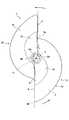
混捏子は、パンなどの材料を捏ねるニーダが備えるポット内に回転自在に配置され、ポットの底面からこの底面に対して直交する方向に立ち上がった回転駆動軸によって回転駆動され、ポット内の材料を混捏するものである。なお、以下の説明においては、混捏子の形状の理解を容易にするために、あたかも2つの羽根部を別個に作製して、これらを一体に接合して混捏子が作製されるかのような説明を行っている。しかし、混捏子の作製にあたっては、例えば、切削加工し、あるいはプレス加工し、その他の適宜の作製方法により、2つの羽根部を一体に作製するのがよい。混捏子の材質としては、適宜のものが選択でき、例えばポリプロピレンなどが選択できる。また、金属で混捏子を作成する場合は、その表面をテフロン(登録商標)処理するとよい。また、混捏子の側面などをエンボス加工するとよい。また、以下の説明において、「長さ」とは、回転駆動軸と直交する方向の距離をいい、「高さ」とは、回転駆動軸方向の距離をいう。図1において、矢印は、混捏子1の回転方向を示しており、この実施例では図1において反時計方向に回転駆動されるように構成されている。また、第1の羽根部21において、符号5a側を回転方向前端とし、符号5b側を回転方向後端とし、省略するが第2の羽根部22も同様の構成を有する。また、第1の羽根部21、第2の羽根部22において、第1の傾斜面2、第2の傾斜面8をそれぞれの羽根部の前面とし、第1の立設面6及び第2の立設面7側をそれぞれの羽根部の後面とする。 The kneading element is rotatably arranged in a pot provided in a kneader that kneads material such as bread, and is rotationally driven by a rotary drive shaft that rises from the bottom surface of the pot in a direction perpendicular to the bottom surface, thereby transferring the material in the pot. It is chaotic. In the following description, in order to facilitate understanding of the shape of the kneading element, it is as if the kneading element is produced by separately manufacturing two blade parts and joining them together. I am explaining. However, in manufacturing the kneading element, for example, it is preferable that the two blade portions are integrally manufactured by cutting or pressing, and other appropriate manufacturing methods. As a material of the kneading element, an appropriate material can be selected, and for example, polypropylene or the like can be selected. When the kneading element is made of metal, the surface is preferably treated with Teflon (registered trademark). Moreover, it is good to emboss the side surface of a kneading element. In the following description, “length” refers to the distance in the direction orthogonal to the rotational drive axis, and “height” refers to the distance in the rotational drive axis direction. In FIG. 1, the arrow indicates the rotation direction of the kneading
図1乃至図6において、混捏子1には、混捏子1を回転駆動軸である駆動手段の図10乃至図12で示すシャフト1001(ニーダに設けられている)と連結可能な軸孔3が形成されている。混捏子1は互いに略相似形状の第1羽根部21と第2羽根部22を一体に有している。第1羽根部21と第2羽根部22は、それぞれ略半円錐状に形成されていて、両羽根部における底面23の周縁形状はそれぞれ直線部と円弧部からなる略半楕円状に形成され、それぞれの底面23の直線部から略垂直に設けられた第1の立設面6と第2の立設面7が互いに平行になるように回転中心軸を中心に点対称に形成されている。ここでは、底面23の2つの直線部と、この2つの直線部と軸孔3との接点をお互いに結んだ線Dによって第1羽根部21と第2羽根部22を分けている。なお、第1羽根部と第2羽根部は互いに略相似形状であれば、多少サイズが異なっていても基本的には本発明の効果を奏するが、ほぼ同一サイズの場合が最も好ましい。 1 to 6, the kneading
混捏子1の羽根部は、シャフト1001を中心にして、その周囲に、等間隔に複数設けることが可能である。本実施例では、同一形状の2つの羽根部を、シャフト1001を中心に点対称に設けている。また、羽根部を、例えば3つにする場合、120度間隔にして一体に形成することもできる。 A plurality of blade portions of the kneading
本実施例において、第1羽根部21と第2羽根部22は、同一形状であるので、主に第1羽根部21の形状を説明する。第2羽根部22は、第1羽根部21にそれぞれ対応した例えば第2の傾斜面8、第2の立設面7を有しているが、それぞれ形状が同一であり第2羽根部22の構成要素の詳細については、省略する。符号12は、第1の傾斜面2の上縁と、立設面6の上縁とに周縁が連接する混捏子1の第1の頂面12を示す。符号13は、第2の傾斜面8の第2の頂面13を示す。混捏子1の全体の頂面9は、第1の傾斜面2、第2の傾斜面8のそれぞれに設けられた略半楕円の第1の頂面12、第2の頂面13の一端を合わせるように形成されている。なお、頂面9の面積は、混捏子1の底面23の面積よりも当然小さくなる。 In the present embodiment, since the
第1羽根部21の前面に形成されている第1の傾斜面2は、混捏子1の頂面12の周縁(略半楕円の曲線部)から底面23に向かって、放物線状に窪んだ曲面で形成されている。同様に第1羽根部21の後面には、第1の立設面6が形成されている。第1の立設面6は、混捏子1の底面23と略直交する方向に絶壁状に設けられている。第1の傾斜面2の回転方向前端5aは、第2の立設面7の半径方向のほぼ中間部に連なっている。また、回転方向前端5aから第1の傾斜面2の回転方向後端5bまでは、上述の円弧部を形成している。回転方向後端5bは、第1の立設面6と連接している。回転方向前面の第1の傾斜面2と、回転方向後面の第1の立設面6は、連なっている。 The first
図3乃至図5に示すように、第1羽根部21の底面23と第1の傾斜面2との間には、第1の立設面6の外縁と、第1傾斜面2の下縁と、底面23とに連接する第3の立設面11が形成されている。第3の立設面11の高さは、回転方向前端5aから回転方向後端5bにかけて漸次高くなっている。なお、第2羽根部22側にも同様にして、第4の立設面10が設けられている。底面23と、第2の立設面7と、第1の傾斜面2の下縁のつなぎ目の部分、すなわち、図3における5aの部分に、円弧状の連続部を設けることで、材料の滞留防止効果をさらに高めるようにしてもよい。同様に底面23と、第1の立設面6と、第2の傾斜面8の下縁のつなぎ目の部分にも同様に、円弧状の連続部を設けることができる。なお、図6で示すように、混捏子1の底面23は、フラットになるように形成されている。 As shown in FIGS. 3 to 5, the outer edge of the
図7において、軸芯3Aから第1羽根部21の回転方向後端5bまでの長さをL1、軸芯3Aから回転方向前端5aまでの長さをL2とする。この場合、第1の羽根部21において、「L1>L2」の関係が成立するように楕円の大きさなどが設定されている。長さL1とL2の間の関係をこのように設定することで、混捏子1とポット内底面間に生地が侵入し付着したとしても、この生地は、各羽根の回転方向後端部の立設面6及び7において落下する生地塊に付着すると同時に、徐々に回転幅が増大する混捏子1の回転に連れて、その底面23の外周によって効率良く掻き出される効果がより高まり、直ちに除去することができる。なお、長さL1は、ポット内底面の半径より若干短めに設定されている。 In FIG. 7, the length from the
本発明者らの実験によれば、長さL1は、長さL2の2.0〜3.5倍が望ましく、ここでは、長さL1は長さL2の約2.5倍に設定されている。さらに、混捏子1の高さは、L1の0.3〜0.7倍が望ましく、第1の傾斜面2の傾斜角度は、20°〜60°が望ましい。なお、上記の各倍率などは、標準的なものであるが、実際の生地魂の動きなどを観察して、適宜、調整をするとよい。材料の処理量を増やす場合には、羽根を大きくする必要性を考慮し、L1が長くなるにしたがって、これらの倍率を小さくするとよい。 According to the experiments by the present inventors, the length L1 is preferably 2.0 to 3.5 times the length L2, and here, the length L1 is set to about 2.5 times the length L2. Yes. Furthermore, the height of the kneading
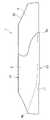
次に、図8、9を参照しながら、第1羽根部21の側面のさらなる詳細について説明する。 Next, further details of the side surface of the
図8は、混捏子1の平面図である。図9は、第1の傾斜面2の断面形状を説明するための図であり、(a)は図8のA−A線、(b)は同図B−B線、(c)は同図C−C線、のそれぞれに沿う断面図で、いずれも回転中心からほぼ放射方向に延びた線に沿っている。図9に示すように、第1の傾斜面2の断面形状は、概して第1羽根部21の底面23の方に窪んで湾曲していて、その曲率は、回転方向前端から後端に向かって次第に小さくなっている。 FIG. 8 is a plan view of the kneading
なお、第1羽根部21の回転方向後端における第1の傾斜面2の断面形状は、図9(C)において曲線2Cで示されるように、ほぼ直線としているが、これに代えて、たとえば、第1羽根部21の底面と反対側(混捏子1の上面側)に凸状に湾曲した曲線となるように第1の傾斜面2を形成してもよい。一方、第2羽根部22の第2の傾斜面8の断面形状も、第1の傾斜面2の断面形状と同様に、第1羽根部21の底面側に湾曲した曲線となるように形成され、かつ、回転方向前端から回転方向後端にかけて、その曲率は次第に小さくなっている。 In addition, although the cross-sectional shape of the 1st inclined
以上説明した傾斜面の断面形状を採用することで、混捏子1の回転に伴って第1、第2の傾斜面(2、8)に乗り上げた材料や生地魂を、第1、第2の傾斜面(2、8)に沿って回転方向後端側にガイドすることができ、この回転方向後端側にガイドされた生地魂などを、ポット内壁(内周面)の法線方向に勢いよく放り投げることができる。その結果、生地魂に対して、ポット内壁の全領域から直接、大きな押圧力を加えることができる。 By adopting the cross-sectional shape of the inclined surface described above, the materials and fabric souls riding on the first and second inclined surfaces (2, 8) with the rotation of the kneading
また、略相似形状の複数の羽根部が接合した形態で一体に形成されていることにより、材料の量が多い場合でも、材料の混捏の効率を良くすることができるため、混捏完了までの時間を短くすることができる。また、略相似形状の羽根部が複数あることで、同じ量の材料を、より低速の回転で混捏することができるため、材料と混捏子との間の摩擦による材料の温度上昇を防ぐことができる。なお、複数の羽根部は、互いに略相似形状であり、本実施例のごとく略同一サイズの場合が最も効果的であるが、異なるサイズであっても十分な効果を奏する。 In addition, since a plurality of substantially similar blade portions are integrally formed in a joined form, even when the amount of material is large, the efficiency of material mixing can be improved. Can be shortened. In addition, since there are a plurality of substantially similar blade portions, the same amount of material can be kneaded at a lower speed, thus preventing temperature rise of the material due to friction between the material and the kneading element. it can. The plurality of blade portions are substantially similar to each other, and are most effective when they have substantially the same size as in the present embodiment. However, even if the sizes are different, sufficient effects can be obtained.
次に、上記混捏子1の、回転駆動軸軸(以下「シャフト」という)への着脱構造について説明する。 Next, a structure for attaching and detaching the kneading
前記混捏子1は、その軸孔3を図10乃至図12に示すシャフト1001に嵌合することによってシャフト1001に連結され、シャフト1001によって回転駆動されるようになっている。シャフト1001は、円柱状の樹脂からなっていて混捏子1を連結する連結部1002と、円柱状のステンレスからなる胴部1003から主に構成されている。シャフト1001の連結部1002は、混捏子1が連結されているとき混捏子1を抜け止めする突部1007と、シャフト1001の軸芯方向から見て、互いに適宜の開き角度を持って形成されている第1の平面1005および第2の平面1004とを有している。また、第1の平面1005と、第2の平面1004は、もともと円柱状の連結部1002の周壁の一部を直線で軸芯方向にカットした形に形成されている。シャフト1001の軸芯方向から見た第2の平面1004から第1の平面1005に渡る開き角度は、略90度に形成されている。 The kneading
図10に示すように、シャフト1001の連結部1002は、先端面から基端近くまで第の平面1004が形成されているのに対して、第1の平面1005の先端部にはこの第1の平面1005の先端部を覆うようにして庇状の突部1007が形成されている。この突部1007は、第2の平面1004側の側面が第2の平面と同一面に形成されている。したがって、シャフト1001の先端面は、D字状の平面からなる連結部1002の上端面で形成されている。庇状の突部1007の下面は混捏子1がシャフト1001から抜け落ちるのを防止する抜け止め面になっていて、この抜け止め面は、下方に凸の略円弧状の傾斜面1007Bによって上記第2の平面1004側の側面につながっている。図12で示すように、突部1007の傾斜面1007Bは、円滑な円弧状ではなく、第2の平面1004に近い側の傾斜角度の大きい面1007Cと、これよりも傾斜角の小さい第1の平面1005側の面1007Dによって2段階にカットされた形に形成されている。シャフト1001の周方向における突部1007の形成範囲のうち、傾斜面1007Bがほぼ3分の2を占め、他のほぼ3分の1はシャフト1001の中心軸線に対して直交する方向の平坦面1007F(図11参照)となっている。なお、傾斜面1007Bは、上述の形状に限らず、円滑な円あるいは楕円の面、その他適宜の形状を選択して採用することができる。 As shown in FIG. 10, the connecting
連結部1002の基端部(下端部)には、第1の平面1005と、第2の平面1004に及ぶ段状の係止部1006が形成されている。係止部1006は、第1の平面1005と第2の平面1004の端部と、連結部1002の周面によって区画されていて、シャフト1001と混捏子1の連結時において、混捏子1をその下側から支持するようになっている。係止部1006の第2の平面1004側は、突部1007の円弧状の傾斜面1007Bの角度1007Aに見合う角度1006Aでシャフト1001の先端側に向かい立ち上がる傾斜面1006Cとなっている。係止部1006の第1の平面1005側は、この第1の平面1005の全域にわたり、シャフト1001の中心軸線に対して直交する方向の平坦面1006Bとなっている。 A first
図1乃至3において、混捏子1の軸孔3は、混捏子1を上下方向に貫いて形成されるとともに、シャフト1001の第1の平面1005との係合平面4Aが軸孔3の軸線方向のほぼ全域にわたり形成され、使用態様における水平方向の横断面形状がD字状になっている。係合平面4Aの上端縁部を軸孔3の上端縁部の若干手前に形成することで、軸孔30の上端縁部領域は段状に形成され、この段状の部分が図10乃至図12に示すシャフト1の連結部2の突部1007と係合する受け部4Bとなっている。なお、係合平面4Aは、軸孔3の上端縁部まで形成されていてもよく、即ち、軸孔3の上端縁部自体を突部1007が係合する受け部としてもよい。 1 to 3, the
上記構成により、混捏子1をシャフト1001に挿入後、混捏子1のみを手動で、所定方向に回転させることにより、シャフト1001に対する装着状態をロックすることができるので、材料を捏ねている途中で、浮力によって混捏子が浮いてしまったり、ひいてはシャフト1001から抜けてしまうことがなく、また、混捏子1をシャフト1001から取り外す際には、混捏子1のみを上記所定方向とは逆方向に手動で回転することにより簡単にロックを解除でき、同時に取り外しが可能な状態になるので、混捏子1のシャフト1001に対する着脱作業が容易であるというところのニーダを提供することができる。なお、混捏子1の軸孔30と、シャフト1001の形状は上述のものに限らず適宜の設計思想により構成することが可能である。 With the above configuration, after the
次に、本発明にかかるニーダの実施の形態について説明する。 Next, an embodiment of a kneader according to the present invention will be described.
図13は、本発明にかかるニーダの実施の形態を示す斜視図である。ニーダ400は、ニーダ本体401と、混捏子1と、ポット300と、を有してなる。ニーダ本体401は、混捏子1を回転させる駆動手段(不図示)や、利用者が混捏子1の回転開始・中断・再開・終了などを指示するボタンや、混捏子1の回転時間を設定するダイヤルなどを有してなる。混捏子1は、ポット300内の材料を混捏する部材であり、先に説明した本発明にかかる混捏子を用いる。ポット300は、材料が投入される混捏用の容器である。なお、ポット3の内周面には、従来のニーダのポットが備える突出部は存在しない。 FIG. 13 is a perspective view showing an embodiment of a kneader according to the present invention. The
ここで、ニーダ400は、約400〜600gの生地量を想定している。そのため、ポット3の内径は、たとえば23.0cm、高さは15.0cm、混捏子1の長手方向長さは12.5cm、高さは3.1cmとなっている。なお、ニーダ400における生地量やポットの大きさは、上述した値に限定せず、適宜最適化するとよい。また、ポット300は、略円筒形状としてもよく、あるいは、底部領域が上方に行くに従い次第にその径を大きくするような形状としてもよい。 Here, the
混捏子1は、ポット300中央部に設けられた上述した回転駆動軸のシャフト1001を受け入れる軸孔を有し、この軸孔に上記シャフト1001を差込み、駆動手段により図中の矢印方向に回転駆動される。なお、本実施の形態では、混捏子1を回転駆動することで、ポット300内の材料を混捏するように構成されているが、混捏子1を回転させることなくポット300を回転させる構成でもよいし、あるいは、混捏子1とポット300の両方を回転させる構成でもよい。混捏子1とポット300の両方を回転させる場合には、互いに逆方向へ回転させる、あるいは、同方向に異なる速度で回転させるように構成してもよい。 The kneading
また、混捏子1あるいはポット300の回転速度は、一定でもよいし、あるいは、ガス抜き時や、材料粉と水とが次第に混ざり合っていく状態変化などに応じて間欠制御若しくは変動させるように構成してもよい。さらには、ニーダ400に、生地の混捏状態を監視するセンサを設けた上で、センサで監視した混捏状態に合わせた速度制御を行う手段を備えるようにしてもよい。 Further, the rotational speed of the kneading
以下、ポット300内に投入された材料が、混捏子1の回転に伴って混捏される様子について、図1他を参照しながら説明する。ポット300内に投入された材料は、混捏子1の回転に伴い、第1羽根部21の底面外周縁及び第1の傾斜面2によりすくい上げられ、第1の傾斜面2上を移動しながら頂面9方向に上昇し、第1の立設面6にて重力により落下する。第1の立設面6より落下した材料は、第2羽根部22の底面23の外周縁の上記円弧部及び第2の傾斜面8によりすくい上げられ、第2の傾斜面8上を移動しながら頂面9方向に上昇し、第2の立設面7にて重力により落下する。以上の動きが繰り返されることで、ポット300内の材料が混合され、紛体状から次第に団子状にまとまり、さらに混捏される。 Hereinafter, a state in which the material charged into the
ここで、生地が混捏子1とポット300内底面間に侵入付着すると、侵入生地は、各羽根の回転方向後端部の立設面6及び7において落下する生地塊に付着すると同時に、底面23の外周縁により、ポット内周面方向に掻き出される。生地塊は、混捏子1の遠心力、及び、混捏子1の側面からの押圧力により、ポット300の内周面方向に押し付けられると同時に、ポット300内周面からも応力としての押圧力を受ける。 Here, when the dough enters and adheres between the kneading
また、生地塊は、通常、混捏子1を被う程度の大きさとなる。そのため、混捏子1の第1、第2の立設面6、7とポット300底面との間に形成される空間は減圧状態になる。その結果、この領域の生地塊はこの空間に吸い込まれ、転倒するように折込まれる。このように、生地塊に対して、いわゆる「手捏ね」、すなわち、生地塊を切断することなく、かつ、生地塊表面に対する摩擦の無い「捏ね」が繰り返される。前述のとおり、本発明の混捏子は、極めて優れた混捏効果を有しているので、従来のニーダでは生地魂の作製が困難とされた「そば生地」であっても、良好な生地魂を、短時間に、かつ、容易に作製することができる。 In addition, the dough lump is usually large enough to cover the
なお、生地塊に対する混捏子1からの押圧力を更に高め、また、ポット300内周面からの生地塊に対する押圧力をより高めるためには、第1、第2の立設面6、7や混捏子1の高さを調節する(より高くする)とよい。さらに、第1傾斜面、第2傾斜面2、8の回転方向後端部断面形状を、直線あるいは外側(混捏子1の上面方向)に突出するように湾曲した曲線状にしてもよい。 In order to further increase the pressing force from the kneading
また、近年、「捏ね」から「焼き」までを全自動で行うことができる各種製パン機(ホームベーカリーなど)が普及してきた。これらの製パン機は、手間をかけずにパンを焼くことができて便利である。しかし、従来の製パン機には、適切な羽根(混捏子)が使用されていないために良好なニーディング(捏ね)が行われにくく、充分な弾性と粘着力を有するグルテンが形成されないという欠点もある。充分かつ良好なグルテンができないと、弾力性のあるふっくらとしたパンはできない。また、従来の製パン機は、ポット内に羽根を残したまま生地を焼くので、焼きあがったパンの底部には羽根による大きな穴ができ、見栄えが悪く、食欲を失うことにもなる。そこで、まず、本発明の混捏子で生地魂を作製し、その後、ポットごと、焼き用ポットと入れ替えるとよい。あるいは、単一の製パン機が、本発明の混捏子を備えた「混捏用ポット」と「焼き用ポット」の両方を備えるように構成してもよい。 In recent years, various bread machines (home bakery, etc.) that can perform all processes from “kneading” to “baking” in a fully automatic manner have become widespread. These bread machines are convenient because they can bake bread without much effort. However, the conventional bread machine does not use appropriate blades (kneading elements), so that it is difficult to perform good kneading, and gluten having sufficient elasticity and adhesive strength is not formed. There is also. If you don't have enough and good gluten, you won't be able to make an elastic and bun. In addition, since the conventional bread maker bakes the dough with the blades left in the pot, a large hole is formed in the bottom of the baked bread, and the appearance is not good and the appetite is lost. Therefore, first, the dough soul is prepared with the kneading element of the present invention, and then the pot and the pot for baking may be replaced. Or you may comprise so that a single bread maker may be provided with both the "kneading pot" and the "baking pot" provided with the kneading element of this invention.
以下、本発明にかかる製パン機の実施の形態について説明する。
図14と図15は、本発明にかかる製パン機の実施の形態を示す模式図であり、製パン機の部分的な断面図である。製パン機100の内部には、パン材料を入れるポットが配置される焼成室101が設けられている。ここで、ポットには、パン材料を混捏する際に用いる混捏用ポット210(図16)と、混捏されたパン材料を加熱する際に用いる焼き用ポット220(図17)の2種類があり、本実施例においてはいずれの形状も有底円筒体であるが、焼き用ポット220については、円筒形状でなく四角柱形状でも良い。混捏用ポット210と焼き用ポット220のいずれも、焼成室101内に着脱可能に配置される。図14は、混捏用ポット210が配置された状態、図15は、焼き用ポット220が配置された状態を示す。Hereinafter, an embodiment of a bread maker according to the present invention will be described.
14 and 15 are schematic views showing an embodiment of a bread maker according to the present invention, and are partial sectional views of the bread maker. Inside the
焼成室101は、開閉自在な蓋102で覆われている。蓋102には、蓋102の開閉用の取っ手103と、製パン機100の利用者が焼成室101内の製パン状態を目視するために覗きこむ覗き窓104が設けられている。 The
図16は、混捏用ポットの構成を説明するための模式図である。混捏用ポット210の内底面には、パン材料の混捏用の上述の混捏子1が配置される。混捏用ポット210の底面中央部には、上述のシャフト1001が設けられている。シャフト1001の一端は、混捏子1の底面に設けられた軸孔3に差込まれ、シャフト1001の他端は、混捏用ポット210の外底面に設けられた従動コネクタ212に取付けられている。 FIG. 16 is a schematic diagram for explaining the configuration of the kneading pot. On the inner bottom surface of the kneading
従動コネクタ212は、凹部を有している。混捏用ポット210を、図示しない手段により焼成室101内に固定したとき、製パン機100内の駆動コネクタ105に取付けられた駆動軸106の一端が従動コネクタ212の凹部に嵌め込まれる。混捏子1は、シャフト1001、従動コネクタ212、駆動コネクタ105、駆動軸106、大プーリ107、ベルト108、小プーリ109、モータ軸110、を介してモータ111により回転駆動される。なお、混捏子1として、前述の本発明にかかる混捏子を用いる。 The driven
図17は、焼き用ポットの構成を説明するための模式図である。焼き用ポット220の内面には、混捏用ポット210に設けられているシャフト1001のような突起物は、設けられていない。焼き用ポット220は、図示しない手段により、焼成室101内に固定されると、製パン機100内の加熱手段であるヒータ112により加熱される。 FIG. 17 is a schematic diagram for explaining the configuration of a baking pot. The inner surface of the
なお、図16、図17に示した混捏用ポットと焼き用ポットの形状は、ポットの上方から下方にかけて略同一径の中空円筒状であるが、いずれのポットの形状もこれに限らず、たとえば、ポットの下方領域は底面から上方にいくに従い漸次径が大きくなり、上方領域は同一径の中空円筒状に形成したものでもよい。 The shape of the kneading pot and the baking pot shown in FIGS. 16 and 17 is a hollow cylindrical shape having substantially the same diameter from the top to the bottom of the pot, but the shape of any pot is not limited to this. The lower region of the pot gradually increases in diameter as it goes upward from the bottom surface, and the upper region may be formed as a hollow cylinder having the same diameter.
モータ111とヒータ112は、製パン機100内の制御手段である制御回路113の命令により動作し、パン材料の混捏工程、熟成工程、ガス抜き工程、仕上げ発酵工程、焼き工程などの製パン工程を行う。製パン機100の上面には、製パン機100の利用者が製パン機を動作させる際に使用する各種ボタンやタイマーなどが設けられた制御パネル114が配置されている。制御回路113は、制御パネル114からの信号などに基づいてモータ111やヒータ112を動作させる命令を発行する。 The
以下、製パン機100による製パン工程について説明する。 Hereinafter, the bread making process by the
(混捏工程について)
混捏工程では、水和を効率的に行わせるために、材料を2回に分けて混捏するところの、いわゆる中種法が採用される。
なお、1回目の混捏と2回目の混捏の間には、所定の休止時間が設けられる。(About the chaotic process)
In the kneading step, a so-called medium seed method is adopted in which the material is kneaded in two portions in order to efficiently perform hydration.
A predetermined pause time is provided between the first chaos and the second chaos.
(熟成工程 その1)
次に、混捏用ポット210内を所定の発酵温度に保持しながら、所定時間、材料を熟成させる。(Aging process part 1)
Next, the material is aged for a predetermined time while keeping the inside of the kneading
(ガス抜き工程 その1)
次に、熟成工程(その1)で膨らんだ生地をつぶし、生地中のガスを除去するために、若干の時間、混捏子1を回転させる。(Degassing part 1)
Next, in order to crush the dough swelled in the ripening step (part 1) and remove the gas in the dough, the kneading
(熟成工程 その2)
次に、混捏用ポット210内を所定の発酵温度に保持しながら、所定時間、材料を熟成させる。(Aging process 2)
Next, the material is aged for a predetermined time while keeping the inside of the kneading
(ガス抜き工程 その2)
次に、熟成工程(その2)で膨らんだ生地をつぶし、生地中のガスを除去するために、若干の時間、混捏子1を回転させる。(Degassing part 2)
Next, in order to crush the dough swelled in the ripening step (part 2) and remove the gas in the dough, the kneading
(生地魂の入れ替え)
次に、ガス抜き工程の終了後、混捏用ポット210を焼成室101から取り出して、焼き用ポット220を焼成室101に設置して、ポットを入れ替える。また、混捏用ポット210内の生地魂を焼き用ポット220に入れ替える。生地魂の入れ替えは、人手で行う。ポットの入れ替えと生地魂の入れ替えの順序は、いずれを先にしてもよい。
なお、ガス抜き工程の終了を製パン機100の利用者に報知する報知手段を製パン機100に設けてもよい。(Replacement of dough soul)
Next, after completion of the degassing step, the kneading
In addition, you may provide the bread-making
(仕上げ発酵工程)
次に、少しだけ温めた焼き用ポット220内に生地魂を所定時間放置して、仕上げの発酵をさせる。(Finishing fermentation process)
Next, the dough soul is left for a predetermined time in the
(焼き工程)
次に、焼き用ポット220内を所定の第1温度に設定して、所定時間、生地を焼く。その後、焼き用ポット220内の温度を第1温度より高い第2温度に上げて、さらに所定時間、生地を焼く。(Baking process)
Next, the inside of the
以上説明した工程を経ることで、製パン機100は、パンの材料の混捏からパンの焼き上げまで行うことができる。ここで、製パン機100がパンの材料を混捏する際に用いる混捏子1は、本発明にかかる混捏子であるため、前述のとおり、生地の良好な混捏が可能であり、充分な弾性と粘着力を有するグルテンが形成され、ふっくらとしたパンを作製することができる。また、焼き用ポット220の内面には突起物が存在せず、また、ポット内に混捏子を取付けることもないため、前述の従来の製パン機のように、焼き上がったパンの底部に大きな穴が形成されることもない。 By going through the steps described above, the
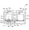
なお、以上説明した製パン機は、混捏用ポットと焼き用ポットとが入れ替え可能に構成されたものであったが、本発明にかかる製パン機はこれに限らず、たとえば、図18に示すように、混捏用ポットと焼き用ポットとが併設可能に構成されたものであってもよい。 Note that the bread making machine described above is configured such that the kneading pot and the baking pot are interchangeable, but the bread making machine according to the present invention is not limited to this, and for example, shown in FIG. In this way, the kneading pot and the baking pot may be configured to be provided side by side.
製パン機100bは、混捏用ポット210が設置される混捏、熟成室101aと、焼き用ポット220が設置される焼成室101bとを有してなる。空間101aは、開閉自在な蓋102aで覆われている。焼成室101bは、開閉自在な蓋102bで覆われている。混捏子1は、図14に示した実施の形態と同様、シャフト1001、従動コネクタ212a、駆動コネクタ105a、駆動軸106a、大プーリ107a、ベルト108a、小プーリ109a、モータ軸110aを介してモータ111aにより回転駆動される。一方、焼き用ポット220は、ヒータ112bにより加熱される。なお、モータ111aとヒータ112a、112bは、制御回路113cが発行する命令に応じて動作する。なお、制御回路113cは、製パン機100bの制御パネル(図示省略)からの信号などに基づいて命令を発行する。 The
この両ポット併設型の製パン機100bの製パン工程は、前述の製パン工程とほぼ同様である。ただし、生地魂の入れ替え工程でのポットの交換は不要である。 The bread making process of the both-pot-equipped
1 混捏子ニーダ本体
2 第1の傾斜面
3 軸孔
4A 平面部
4B 受け部
5 回転方向前端部
6 第1の立設面
7 第2の立設面
8 第2の傾斜面
9 頂面
10 第4の立設面
11 第3の立設面
21 第1羽根部
22 第2羽根部
23 底面DESCRIPTION OF
Claims (10)
Translated fromJapaneseこの軸孔が上記回転駆動軸に嵌合し、上記回転駆動軸が回転することにより回転駆動されて材料を混捏するニーダの混捏子、であって、
略相似形状の複数の羽根部が、上記回転駆動軸を中心に周方向に等間隔、かつ、一体に成型され、
上記複数の羽根部のそれぞれには、回転方向前面に傾斜面が形成され、回転方向後面に上記傾斜面と連なる立設面が形成されていることを特徴とするニーダの混捏子。A shaft hole for receiving the rotary drive shaft;
A kneader kneader in which the shaft hole is fitted to the rotational drive shaft and is rotationally driven by the rotational drive shaft rotating to mix the materials,
A plurality of substantially similar blade portions are equally spaced in the circumferential direction around the rotation drive shaft, and are integrallymolded,
A kneader for a kneader characterized in that aninclined surface is formed on the front surface in the rotational direction and a standing surface connected to the inclined surface is formed on the rear surface in the rotational direction in each of the plurality of blade portions .
上記混捏子は、請求項1に記載のニーダの混捏子であることを特徴とするニーダ。 2. The kneader according to claim 1, wherein the kneading element is a kneading element of the kneader according to claim 1.
上記混捏用ポット内に取付けられてパンの材料を混捏する混捏子は、請求項1に記載のニーダの混捏子であることを特徴とする製パン機。 The bread maker according to claim 1, wherein the kneading element attached to the kneading pot and kneading bread material is the kneader of the kneader according to claim 1.
Priority Applications (1)
| Application Number | Priority Date | Filing Date | Title |
|---|---|---|---|
| JP2010235403AJP5097813B2 (en) | 2010-10-20 | 2010-10-20 | Nida chaos, Nida and bread machine |
Applications Claiming Priority (1)
| Application Number | Priority Date | Filing Date | Title |
|---|---|---|---|
| JP2010235403AJP5097813B2 (en) | 2010-10-20 | 2010-10-20 | Nida chaos, Nida and bread machine |
Publications (2)
| Publication Number | Publication Date |
|---|---|
| JP2012085580A JP2012085580A (en) | 2012-05-10 |
| JP5097813B2true JP5097813B2 (en) | 2012-12-12 |
Family
ID=46257924
Family Applications (1)
| Application Number | Title | Priority Date | Filing Date |
|---|---|---|---|
| JP2010235403AExpired - Fee RelatedJP5097813B2 (en) | 2010-10-20 | 2010-10-20 | Nida chaos, Nida and bread machine |
Country Status (1)
| Country | Link |
|---|---|
| JP (1) | JP5097813B2 (en) |
Family Cites Families (7)
| Publication number | Priority date | Publication date | Assignee | Title |
|---|---|---|---|---|
| JPS5913942Y2 (en)* | 1980-06-23 | 1984-04-24 | 松下電器産業株式会社 | bread making machine |
| JPS62126928A (en)* | 1985-11-29 | 1987-06-09 | 大地 修造 | Kneader |
| JPS62132528A (en)* | 1985-12-03 | 1987-06-15 | Shuzo Ochi | Kneader |
| JPH0538828Y2 (en)* | 1989-05-29 | 1993-09-30 | ||
| JPWO2003073860A1 (en)* | 2002-03-06 | 2005-06-23 | 株式会社愛工舎製作所 | Kneading device of kneading device and kneading device equipped with this kneading device |
| JP3970919B1 (en)* | 2007-04-10 | 2007-09-05 | 株式会社サンジーバー | Nida chaos and Nida and bread machine |
| JP4468483B2 (en)* | 2007-08-20 | 2010-05-26 | 日本ニーダー株式会社 | Nida chaos and Nida and bread machine |
- 2010
- 2010-10-20JPJP2010235403Apatent/JP5097813B2/ennot_activeExpired - Fee Related
Also Published As
| Publication number | Publication date |
|---|---|
| JP2012085580A (en) | 2012-05-10 |
Similar Documents
| Publication | Publication Date | Title |
|---|---|---|
| US8307757B2 (en) | Kneading element of kneader, kneader, and bread machine | |
| KR101836790B1 (en) | A kneading device for kneading ingredients into dough and a kneading tool | |
| CN103300747B (en) | Bread dough generates machine and bakery equipment | |
| JP3970919B1 (en) | Nida chaos and Nida and bread machine | |
| CN110663725B (en) | Multifunctional dough making machine | |
| JP6172606B2 (en) | Automatic bread machine | |
| JP5097813B2 (en) | Nida chaos, Nida and bread machine | |
| JP4468483B2 (en) | Nida chaos and Nida and bread machine | |
| JP5824617B2 (en) | Bread dough producing machine and bread making machine using the dough | |
| CN209996136U (en) | Stirring mechanism, dough cup assembly and wheaten food processing device | |
| CN203483306U (en) | Automatic bread maker | |
| HK1138744A (en) | Kneading member of kneader, kneader, and bread machine | |
| JP5161940B2 (en) | Kneader and bread machine | |
| WO2012056764A1 (en) | Automatic bread maker | |
| JPH05154056A (en) | Bread making machine and method of making bread using the bread making machine | |
| JP2010246491A (en) | Pot for kneader, the kneader, and bread-baking machine | |
| CN214284592U (en) | Air fryer with stirring function | |
| CN217524721U (en) | Stirring knife assembly and automatic cake machine comprising same | |
| CN205161704U (en) | Stirring thin pancake device | |
| CN103767560B (en) | Automatic bread maker | |
| JP2011152271A (en) | Automatic bread maker | |
| JP5516325B2 (en) | Automatic bread machine | |
| CN103654445B (en) | Automatic bread baking machine | |
| JP5957738B2 (en) | Automatic bread machine | |
| WO2010015100A1 (en) | Inclined style automatic toaster |
Legal Events
| Date | Code | Title | Description |
|---|---|---|---|
| TRDD | Decision of grant or rejection written | ||
| A01 | Written decision to grant a patent or to grant a registration (utility model) | Free format text:JAPANESE INTERMEDIATE CODE: A01 Effective date:20120911 | |
| A01 | Written decision to grant a patent or to grant a registration (utility model) | Free format text:JAPANESE INTERMEDIATE CODE: A01 | |
| A61 | First payment of annual fees (during grant procedure) | Free format text:JAPANESE INTERMEDIATE CODE: A61 Effective date:20120924 | |
| R150 | Certificate of patent or registration of utility model | Free format text:JAPANESE INTERMEDIATE CODE: R150 | |
| FPAY | Renewal fee payment (event date is renewal date of database) | Free format text:PAYMENT UNTIL: 20150928 Year of fee payment:3 | |
| LAPS | Cancellation because of no payment of annual fees |