JP5096503B2 - Environmental test equipment - Google Patents
Environmental test equipmentDownload PDFInfo
- Publication number
- JP5096503B2 JP5096503B2JP2010001983AJP2010001983AJP5096503B2JP 5096503 B2JP5096503 B2JP 5096503B2JP 2010001983 AJP2010001983 AJP 2010001983AJP 2010001983 AJP2010001983 AJP 2010001983AJP 5096503 B2JP5096503 B2JP 5096503B2
- Authority
- JP
- Japan
- Prior art keywords
- cover
- heat
- container
- shutter
- region
- Prior art date
- Legal status (The legal status is an assumption and is not a legal conclusion. Google has not performed a legal analysis and makes no representation as to the accuracy of the status listed.)
- Active
Links
Images


Landscapes
- Testing Resistance To Weather, Investigating Materials By Mechanical Methods (AREA)
Description
Translated fromJapanese本発明は、容器内の空調を実施する環境試験装置に関わる。 The present invention relates to an environmental test apparatus that performs air conditioning in a container.
容器内の空調を実施する環境試験装置には特許文献1のような方式を採用するものがある。特許文献1では、容器内に設けられた試験室の空調を実施するため、ヒートパイプを用いた熱交換器が設けられている。ヒートパイプの一端は試験室内に、他端は試験室外のダクトに配置されている。ダクトの下部には、ダクト内に気流を発生させるファンが設けられている。このファンによってダクト内に気流が発生すると、ヒートパイプのダクト側の他端が冷却される。これによりヒートパイプの両端間に温度差が生じると、ヒートパイプの試験室側の一端からダクト側の他端へと熱伝導が生じ、試験室内が冷却される。 Some environmental test apparatuses that perform air conditioning in a container employ a system such as that disclosed in
特許文献1の熱交換器の場合、ヒートパイプの両端間に温度差があるときには、ヒートパイプを介した熱伝導が継続する。このため、容器内が所望の温度になった際にファンを停止しても、ヒートパイプを介して容器内がさらに冷却され、容器内が所望の温度より低くなることがある。そこで、特許文献1では、試験室内の温度が所望の温度より低くなると、ダクト下部のファンを止めた状態で、試験室内に設けたヒータを作動させている。このように特許文献1では、容器内を所望の温度に保つためにヒータを作動させる必要があるので、エネルギー効率が低くなるおそれがある。 In the case of the heat exchanger of
本発明の目的は、エネルギーの消費を抑制しつつ容器内を所望の温度に保ちやすい環境試験装置を提供することにある。 The objective of this invention is providing the environmental test apparatus which is easy to maintain the inside of a container at desired temperature, suppressing consumption of energy.
本発明の環境試験装置は、内部に試験室が形成された容器と、前記容器内に一端が、前記容器外に他端が配置され、両端間に生じた温度差により両端間で熱伝導が発生する熱伝導部材と、前記熱伝導部材の他端を上方から覆うカバーと、前記カバーに形成された開口と、前記開口から前記カバー外へと空気を流出させるような気流を前記カバー内に発生させる気流発生手段とを備えており、前記熱伝導部材は、内部に冷媒が封入されたパイプ部材を有し、前記パイプ部材において前記一端側の部分である前記容器内の部分で蒸発した冷媒が、前記パイプ部材において前記他端側の部分である前記容器外の部分で凝縮することにより前記容器内を冷却するものであり、前記気流発生手段を制御して、前記カバー内における前記熱伝導部材の他端の周囲に前記熱伝導部材からの放熱により暖められた空気を滞留させることにより、前記熱伝導を抑制する。
The environmental test apparatus according to the present invention includes a container in which a test chamber is formed, one end inside the container, and the other end outside the container, and heat conduction between both ends due to a temperature difference generated between both ends. A heat conducting member that is generated, a cover that covers the other end of the heat conducting member from above, an opening formed in the cover, and an air flow that causes air to flow out of the cover from the opening into the cover. An airflow generating means for generating therefrigerant ,wherein the heat conducting member has a pipe member in which a refrigerant is sealed, and the refrigerant evaporated in a portion of the pipe member that is the one end side portion of the container. However, the pipe member cools the inside of the container by condensing in a portion outside the container that is the other end side portion, and controls the air flow generation means to control the heat conductionin the cover. The other end of the memberBy staying the air warmedby the heat radiation from the heat-conducting memberaround, suppressing the thermal conduction.
本発明の環境試験装置によると、熱伝導部材の他端が上方からカバーで覆われており、このカバーが熱伝導部材の他端の周囲に暖められた空気を滞留させる。このため、カバー内の気流の発生を停止すると、熱伝導部材の他端からの放熱が収まり、熱伝導部材の両端間の温度差が解消される。したがって、熱伝導部材を介した熱伝導が発生しにくくなるため、容器内が冷却され過ぎたりしにくくなる。また、熱伝導部材は、内部に冷媒が封入されたパイプ部材を有し、一端側の部分で蒸発した冷媒が他端側の部分で凝縮することで容器内を冷却するので、このような冷媒の循環により熱伝導が効率よく発生する。
According to the environmental test apparatus of the present invention, the other end of the heat conducting member is covered with a cover from above, and this cover retains warmed air around the other end of the heat conducting member. For this reason, when generation | occurrence | production of the airflow in a cover is stopped, the heat radiation from the other end of a heat conductive member will be settled, and the temperature difference between the both ends of a heat conductive member will be eliminated. Therefore, since heat conduction through the heat conducting member is less likely to occur, the inside of the container is hardly cooled.Further, the heat conducting member has a pipe member in which a refrigerant is sealed, and the refrigerant evaporated in the one end side portion is condensed in the other end side portion so that the inside of the container is cooled. The heat conduction is efficiently generated by the circulation.
また、本発明においては、前記熱伝導部材の他端を加熱する加熱手段をさらに備えていることが好ましい。これによると、加熱手段により熱伝導部材の他端が加熱されるため、熱伝導部材の両端間に生じた温度差を速やかに解消できる。 Moreover, in this invention, it is preferable to further provide the heating means which heats the other end of the said heat conductive member. According to this, since the other end of the heat conducting member is heated by the heating means, the temperature difference generated between the both ends of the heat conducting member can be quickly eliminated.
また、本発明においては、前記カバーが、前記熱伝導部材が前記容器内から前記カバー内に熱伝導によって放散する熱量より、前記カバー内から前記カバー外へと放散する熱量が小さくなるような断熱性能を有していることが好ましい。これによると、カバー内の温度が保持されやすい。 Further, in the present invention, the cover is insulated so that the amount of heat dissipated from the inside of the cover to the outside of the cover is smaller than the amount of heat dissipated by the heat conducting member from the inside of the container to the inside of the cover by heat conduction. It is preferable to have performance. According to this, the temperature in the cover is easily maintained.
また、本発明においては、前記カバー内の領域を、前記熱伝導部材の他端が配置された第1の領域と前記開口を通じて前記カバー外の空間と連続する第2の領域とに仕切る内壁が、前記カバー内に設けられていることが好ましい。これによると、カバー内の空間が2つに仕切られているため、仕切りがない場合と比べてカバー内の温度が保持されやすい。 In the present invention, an inner wall that divides the region in the cover into a first region where the other end of the heat conducting member is disposed and a second region that is continuous with the space outside the cover through the opening. The cover is preferably provided in the cover. According to this, since the space in the cover is partitioned into two, the temperature in the cover is easily maintained as compared with the case where there is no partition.
また、本発明においては、前記第1の領域と前記第2の領域との連通部に配置され、前記連通部を閉鎖する閉鎖位置と前記連通部を開放する開放位置とを選択的に取るシャッタと、前記気流発生手段が気流を発生させた際に前記シャッタを前記閉鎖位置から前記開放位置へと変位させるシャッタ変位手段とをさらに備えていることが好ましい。これによると、気流が発生する際はシャッタが開放位置を取るので熱伝導部材の他端が適切に冷却されると共に、シャッタが閉鎖された場合は、暖められた空気がカバー内に溜まりやすくなる。 In the present invention, the shutter is disposed at the communication portion between the first region and the second region, and selectively takes a closed position for closing the communication portion and an open position for opening the communication portion. And a shutter displacing means for displacing the shutter from the closed position to the open position when the airflow generating means generates an airflow. According to this, when the airflow is generated, the shutter takes the open position, so that the other end of the heat conducting member is appropriately cooled, and when the shutter is closed, the warmed air easily collects in the cover. .
また、本発明においては、前記シャッタ変位手段が、前記閉鎖位置を取るように前記シャッタを付勢する付勢手段を有しており、前記気流発生手段が、前記第1の領域と前記第2の領域の間に発生した圧力差が、前記付勢手段による付勢力に抗して、前記シャッタを前記閉鎖位置から前記開放位置へと移動させるような気流を発生させることが好ましい。これによると、付勢手段により、気流が発生する際はシャッタが開放位置を取り、気流が停止した際はシャッタが閉鎖位置を取るので、シャッタを適切に変位させる構造が簡易に実現する。 In the present invention, the shutter displacing means includes urging means for urging the shutter so as to take the closed position, and the airflow generating means includes the first region and the second region. It is preferable that a pressure difference generated between the two regions generates an air flow that moves the shutter from the closed position to the open position against the urging force of the urging means. According to this, since the shutter takes the open position when the airflow is generated and the shutter takes the closed position when the airflow stops, the structure for appropriately displacing the shutter is easily realized.
また、本発明においては、前記気流発生手段が、前記開口の近傍に配置されたファンを有していることが好ましい。これによると、気流の流出口であるカバーの開口の近傍にファンが配置されているので、第1の領域内に均一な気流を発生させやすく、気流によって熱伝導部材の他端を冷却する効率がよい。 Moreover, in this invention, it is preferable that the said airflow generation means has the fan arrange | positioned in the vicinity of the said opening. According to this, since the fan is disposed in the vicinity of the opening of the cover that is the outlet of the airflow, it is easy to generate a uniform airflow in the first region, and the efficiency of cooling the other end of the heat conducting member by the airflow Is good.
また、本発明においては、前記開口が、前記内壁の上端より下方に配置されていることが好ましい。さらに、前記カバーが、前記熱伝導部材の上方に配置された第1の壁部と、前記容器との間に前記熱伝導部材の他端を挟む位置に配置された第2の壁部とを有しており、前記第1及び第2の壁部と前記容器との間に形成される前記カバーの内包空間内に前記暖められた空気が滞留することが好ましい。 Moreover, in this invention, it is preferable that the said opening is arrange | positioned below the upper end of the said inner wall. Further, the cover includes a first wall portion disposed above the heat conducting member, and a second wall portion disposed at a position sandwiching the other end of the heat conducting member between the container and the container. It is preferable that the warmed air stays in an inner space of the cover formed between the first and second wall portions and the container.
以下、本発明の環境試験装置が適用された一実施形態である環境試験装置1について図面を参照しつつ説明する。なお、以下の説明において上方、下方、前方、後方、右方及び左方の各方向は、図2に示された方向を指すものとする。 Hereinafter, an
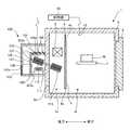
環境試験装置1は、電子部品等の試料に関して環境試験を実施する際に用いられる装置であり、図1に示すように、断熱容器2を有している。断熱容器2の内部には、試料が配置される空間である試験室が設けられている。試験室内は、仕切り壁4によって前後方向に2つの空間1a及び1bに仕切られており、空間1b内に試料Mが載置される載置台7が設けられている。空間1bの前方には開閉可能な断熱扉3が設けられており、試験室内において試料Mの環境試験を実施する際には、断熱扉3を開放して断熱容器2の前方から試料Mを空間1b内に収容し、試料Mを載置台7に載置した後、断熱扉3を閉じて試験室を密閉する。 The
空間1a内には試験室内を加熱するためのヒータ5が設けられている。仕切り壁4の上端と断熱容器2内の天井壁面との間には連通口4aが形成され、仕切り壁4の下端と断熱容器2内の底壁面との間には連通口4bが形成されている。連通口4aにはファン6が設けられており、ファン6が作動すると、空間1aの空気が連通口4aを通じて空間1b側へと流入すると共に、空間1bの空気が連通口4bを通じて空間1a側へと流入する。 A
また、環境試験装置1には、図1及び図2に示すように、空間1a内の空気を冷却するための熱交換器100が設けられている。熱交換器100は、自然循環冷媒回路110(熱伝導部材)を有している。自然循環冷媒回路110は、内部が中空の複数のヒートパイプ111(パイプ部材)と、ヒートパイプ111の両端部にそれぞれ固定されたフィン112及び113とを有している。フィン112及び113は、ヒートパイプ111と空気間の熱交換の効率を向上させる部材である。ヒートパイプ111は断熱容器2の後部側壁2aを貫通しており、フィン112が固定された方の端部が断熱容器2の外部に配置され、フィン113が固定された方の端部が断熱容器2内の空間1aに配置されている。また、フィン112が固定された方の端部が、フィン113が固定された方の端部より上方に配置されている。 Moreover, as shown in FIG.1 and FIG.2, the
ヒートパイプ111内には冷媒が封入されている。空間1a内の温度が高温になると、ヒートパイプ111のフィン113側の端部において内部の冷媒が蒸発し、その蒸気がフィン112側へと向かう。ヒートパイプ111のフィン112側の端部においては、内部の蒸気が凝縮し、液体となる。ヒートパイプ111はフィン113側が下方になるように傾斜しているので、重力の影響と毛管力により、フィン112側の端部において凝縮した液体が、フィン113側へと流れていく。つまり、ヒートパイプ111においてフィン113側の端部では端部周辺の空気から蒸発熱を奪って冷媒が蒸発する。一方、ヒートパイプ111においてフィン112側の端部では端部周辺の空気へと放熱して冷媒が凝縮する。凝縮した冷媒はフィン113側へと戻る。このような冷媒の自然循環により、ヒートパイプ111においてフィン113側からフィン112側へと熱伝導が発生し、断熱容器2内部が冷却される。 A refrigerant is sealed in the
このように自然循環冷媒回路110では、両端間の温度差に応じて冷媒が自然に循環することで、エネルギーを消費することなく断熱容器2内の空気を冷却することが可能である。しかし、この方式を採用した場合、断熱容器2内の温度が所望の温度になったとしても、ヒートパイプ111の両端間に生じた温度差に応じて熱伝導が発生するため、断熱容器2内の冷却が進行する。したがって従来、断熱容器2内の温度が所望の温度より低下し過ぎないように、断熱容器2内のヒータ5を作動させ、断熱容器2内を加熱する必要があった。 As described above, in the natural circulation
そこで、本実施形態の熱交換器100には、自然循環冷媒回路110において必要以上に熱伝導を生じさせないようにするため、ヒートパイプ111のフィン112側の端部を覆う外カバー101及び内カバー102が設けられている。外カバー101はフィン112の上方、下方、後方、左方及び右方のそれぞれに配置された壁部から構成され、断熱容器2の後部側壁2aの背面に固定されている。自然循環冷媒回路110は、断熱容器2の外側に配置された領域の全体が、外カバー101と後部側壁2aの背面との間に形成された外カバー101内の空間に収容されている。外カバー101の後部の下端付近には外カバー101の内部と外部とを連通させる開口101aが形成されている。開口101aには外カバー101内の空気を外カバー101外へと流出させるファン103(気流発生手段)が設けられている。外カバー101においてフィン112の下方には開口101bが形成されている。 Therefore, in the
外カバー101の内部には内カバー102が形成されている。内カバー102はフィン112の後方及び上方にそれぞれ配置された壁を有しており、これらの壁が、外カバー101内の空間を、フィン112が配置された領域106(第1の領域)と、開口101aを通じて外カバー101外の領域と連続する領域107(第2の領域)とに仕切っている。領域106内には、フィン112を加熱するヒータ105(加熱手段)が設けられている。内カバー102においてフィン112の上方には、領域106と領域107を連通させる連通口102aが開口している。 An
外カバー101及び内カバー102は、なるべく高い断熱性を有する構造であることが好ましい。少なくとも、ヒートパイプ111の放熱量を保持できる程度に断熱性能の高い材質である必要がある。具体的には、自然循環冷媒回路110の熱伝導によって断熱容器2内から内カバー102内へと単位時間当たりに放散される熱量より、内カバー102内から外カバー101外へと単位時間当たりに放散される熱量の方が小さくなるように、外カバー101及び内カバー102が構成されている。外カバー101及び内カバー102には、例えば、樹脂材料からなる素材、特に発泡スポンジ、発泡スチロールなどの発泡性の素材が用いられるとよい。 It is preferable that the
内カバー102の上部に形成された連通口102aには、この連通口102aを開閉するシャッタ104が設けられている。シャッタ104は、連通口102aを開放する開放位置(図1に示された位置)と連通口102aを閉鎖する閉鎖位置(図2に示された位置)との間で変位可能に設けられている。また、シャッタ104を連通口102aに変位可能に支持する支持部104aには、シャッタ104の支持部を回転方向に付勢するばねなどの付勢部材が設けられている。この付勢部材は、シャッタ104を開放位置から閉鎖位置へ向かう方向に付勢している。 A
ファン103が作動していない状態では、シャッタ104は上記の付勢部材により、閉鎖位置を取った状態で維持されている。ファン103が作動すると外カバー101内の領域107の気圧が大気圧より小さくなるため、領域106と領域107の間で気圧に差が生じる。この圧力差が付勢部材による付勢力より大きくなると、シャッタ104に作用する圧力が付勢力に抗し、シャッタ104が閉鎖位置から開放位置へと変位する。これによって連通口102aが開放されると、フィン112の下方に形成された開口101bから空気が流入し、領域106を通過して連通口102aを通り、領域107から開口101aを介して外カバー101外へと向かう気流が発生する。この気流により、シャッタ104は開放位置を取った状態で維持される。ファン103が停止すると、この気流が停止し、シャッタ104は再び閉鎖位置を取る。このように、本実施形態では、付勢部材の働きにより、ファン103が作動した際にシャッタ104を開放させる、本発明のシャッタ変位手段の機能が実現されている。 When the
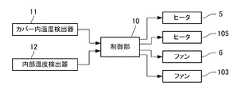
環境試験装置1の各部は、図1及び図3に示すように、制御部10によって制御されている。制御部10は、CPU(Central Processing Unit)や各種メモリなどのハードウェアと、これらのハードウェアを環境試験装置1の各部を制御する機能部として機能させるソフトウェアとによって構成されている。制御部10には内カバー102内の温度を検出するカバー内温度検出器11と、断熱容器2内の温度を検出する内部温度検出器12とが接続されている。制御部10は、カバー内温度検出器11の検出結果及び内部温度検出器12の検出結果に基づいてヒータ5及び105、並びに、ファン6及び103をそれぞれ制御する。 Each part of the
例えば、断熱容器2内の温度を低下させる際、制御部10は、ファン6及び103を作動させると共に、ヒータ5及び105を停止させる。ファン103が作動することにより、連通口102aが開放され、開口101bから外カバー101内に流入した空気がフィン112の周辺を通って開口101aから流出する気流が発生する。この気流によってフィン112が冷却され、ヒートパイプ111においてフィン112側とフィン113側との間に温度差が生じる。これによって、ヒートパイプ111においてフィン113側からフィン112側へと熱伝導が発生し、断熱容器2の空間1a内の空気が冷却される。空間1a内の冷却された空気は、ファン6によって空間1bへと流入し、試験室内の温度が低下する。 For example, when the temperature in the
また、制御部10は、カバー内温度検出器11及び内部温度検出器12の検出結果に基づき、断熱容器2内と内カバー102内の温度差に応じてファン103の回転数を制御する。例えば、自然循環冷媒回路110において所定の冷却能力を確保したい場合、断熱容器2内と内カバー102内の温度差が大きいときには、ファン103の回転数を小さくする一方で、断熱容器2内と内カバー102内の温度差が小さいときにはファン103の回転数を大きくする。このように、ファン103の運転制御により、自然循環冷媒回路110による冷却能力の制御が可能である。 Further, the
試験室内の温度が所望の温度付近まで低下すると、制御部10は、ファン103を停止させる。これにより、シャッタ104が閉鎖状態となる。このとき、自然循環冷媒回路110においてフィン112側の端部とフィン113側の端部とで温度差が生じ、ヒートパイプ111を通じて熱伝導が発生したとしても、フィン112からの放熱によって暖められた空気は領域106内において、閉鎖されたシャッタ104の直下に滞留する。これによってフィン112の周囲の空気が次第に暖まり、フィン112側の放熱が収まって、自然循環冷媒回路110においてフィン112側とフィン113側との温度差が解消されてくる。このため、ヒートパイプ111を通じた熱伝導が発生しにくくなり、試験室内の温度が所望の温度よりも低下し過ぎるのが抑制される。 When the temperature in the test chamber decreases to near the desired temperature, the
さらに、制御部10は、カバー内温度検出器11及び内部温度検出器12の検出結果に基づき、ヒータ105を作動させる。例えば、断熱容器2内と内カバー102内で温度差が大きいと、自然循環冷媒回路110の両端間での温度差も大きくなっていると考えられる。したがって、ファン103を停止させるだけでは自然循環冷媒回路110の両端間の温度差が小さくなりにくく、試験室内の温度が所望の温度よりも低下し過ぎるのを有効に抑制できないおそれがある。そこで、断熱容器2内と内カバー102内で温度差が大きい場合のように、自然循環冷媒回路110による冷却を速やかに停止させる必要がある場合、制御部10はファン103を停止させると共に、ヒータ105を作動させる。これにより自然循環冷媒回路110においてフィン112側の端部が加熱され、フィン112側の端部とフィン113側の端部との温度差が速やかに解消される。また、領域106内の空気がヒータ105によって暖められ、フィン112からの放熱が収まる。これらにより、ヒートパイプ111を通じた熱伝導が停止し、自然循環冷媒回路110による冷却が速やかに停止する。 Further, the
以上説明した本実施形態によると、外カバー101、内カバー102及びシャッタ104により、暖められた空気が領域106内に滞留するため、ファン103を停止した際、自然循環冷媒回路110によって断熱容器2内を冷却し過ぎるのが防止される。また、外カバー101及び内カバー102が断熱性の高い材質で構成されているため、暖められた空気が領域106内に溜まりやすい。なお、外カバー101及び内カバー102の断熱性能を調整することでも、熱交換器100全体の冷却性能を調整できる。例えば、外カバー101及び内カバー102の断熱性能を高くするほど熱交換器100全体の冷却性能を下げることができる。逆に、外カバー101及び内カバー102の断熱性能を低くすると、断熱容器2内から常時放出する熱量の調整が可能になり、環境試験装置1の基本性能、例えば、温度が上昇したり降下したりする際の温度変化の速さなどをある程度調整することができる。 According to the present embodiment described above, since the warmed air stays in the
また、本実施形態では、外カバー101内にさらに内カバー102が設けられ、その内部にフィン112が配置されている。つまり、フィン112を覆うカバーが2層に構成されており、領域107のさらに内部の領域106に暖められた空気が溜まるように構成されている。これにより、領域107で空気層による断熱機能が発揮されるため、領域106内の暖められた空気の温度が保持されやすく、自然循環冷媒回路110による冷却が速やかに停止する。 In the present embodiment, an
また、本実施形態では、外カバー101内から空気を流出させる側の開口である開口101aにファン103が設けられている。一方、外カバー101内へと空気を流入させる側の開口である開口101bにファン103を設けてもよい。しかし、開口101bにファン103を設けて領域106内に空気を流入させると、フィン112の周辺に発生する気流は局部的になりやすく、気流が当たっている部分しか冷却されない。このため、気流によるフィン112の冷却効率が比較的悪い。これに対して本実施形態では、空気の流出側である開口101aにファン103を設けているため、領域106内に均一に気流を発生させやすい。したがって、気流によるフィン112の冷却効率が良い。 Further, in the present embodiment, the
なお、自然循環冷媒回路110による冷却を速やかに停止させる必要がある場合には上記の通りヒータ105を作動させるが、これによって自然循環冷媒回路110による冷却が速やかに停止すると、断熱容器2内のヒータ5を作動させる必要がない。このため、断熱容器2内のヒータ5を作動させる必要がある場合と比べてエネルギー効率が大きく悪化することはない。また、空間1a内で熱交換器100による冷却とヒータ5による加熱が同時になされると、空間1a内で空気の温度むらにより温度分布のばらつきが発生するおそれがあるが、本実施形態では上記のようにヒータ5を作動させる必要がないため、このような温度ばらつきを抑制できる。 In addition, when it is necessary to quickly stop the cooling by the natural circulation
以下、本実施形態の熱交換器100における変形例について説明する。本変形例は、上述の外カバー101及び内カバー102の代わりに、図4(a)及び図4(b)に示すカバー201を有している。カバー201内の空間は仕切り壁202によって、前方の領域206及び後方の領域207に仕切られている。フィン112は領域206内に配置されている。仕切り壁202の上端とカバー201の上壁との間には、領域206と領域207を連通させる連通口202aが形成されている。本変形例では、連通口202aにはシャッタ104のようなシャッタが設けられていないが、シャッタが設けられてもよい。 Hereinafter, the modification in the
カバー201において領域207の下端には開口201aが形成され、カバー201において領域206の下端には開口201bが形成されている。開口201aは開口201bより上方に配置されている。開口201bにはファン203が設けられており、ファン203は、カバー201外の空気をカバー201内へと流入させる。カバー201内に流入した空気は、フィン112の周辺を通って領域206の上部へと向かい、そこから連通口202aを通じて領域207へと流れ込み、開口201aから外部へと流出する。開口201aは連通口202aより下方に配置されているので、ファン203が停止すると、領域206及び207の上部に暖かい空気が滞留しやすく、これによって自然循環冷媒回路110による試験室内の冷却が停止しやすい。このため、本変形例においても、上述の実施形態と同様、試験室内の温度が所望の温度よりも低下し過ぎるのが抑制される。 An
上述の実施形態では、空気の流出口である開口101aが外カバー101の下端付近に配置されていたが、本変形例の開口201aのように、空気の流出口が比較的高い位置に配置されていてもよい。 In the above-described embodiment, the
図5(a)〜図5(d)は、カバーの開口及び仕切り壁の形状が図4とは異なるさらに別の変形例をそれぞれ示している。図4(b)の開口201aは水平に沿って形成されているが、図5(a)〜図5(c)の開口301a〜501aのように、上方に向かって切れ込みが形成されてもよい。これにより、空気が流出口を通過する際の圧力損失を種々に変化させることができる。また、図4(b)の仕切り壁202の上端は水平に沿っているが、図5(a)〜図5(c)の仕切り壁302〜502のように、上方に凸の形状に形成されてもよい。さらに、図5(d)に示すように、開口601aの下端や仕切り壁602の上端に凹凸が形成されていてもよい。なお、開口201aと仕切り壁302が組み合わされたり、開口401aと仕切り壁202が組み合わされたりなど、開口201a〜601aの形状と仕切り壁202〜602の形状が適宜組み合わされて用いられてもよい。 FIG. 5A to FIG. 5D show still other modified examples in which the opening of the cover and the shape of the partition wall are different from those in FIG. 4. Although the
図4や図5(a)〜図5(d)に示すように、空気の流出口や仕切り壁の形状を様々に調整することで空気が通過する際の圧力損失を調整できる。これにより、例えば図4の変形例ではファン203の回転数に対してカバーから流出する風量が線形的に変化しない場合に、図5(a)〜図5(d)のようなカバー形状にして圧力損失を変化させることで、ファン203の回転数に対してカバーから流出する風量を線形的に変化させるようにすることができる。このように、ファン203の回転数に対する風量を変化させることにより、フィン112に当てる風量を変化させ、自然循環冷媒回路110の冷却能力に対するファン203の制御特性を変化させることができる。 As shown in FIGS. 4 and 5 (a) to 5 (d), the pressure loss when air passes can be adjusted by variously adjusting the shape of the air outlet and the partition wall. Thus, for example, in the modified example of FIG. 4, when the airflow flowing out from the cover does not change linearly with respect to the rotational speed of the
<その他の変形例>
以上は、本発明の好適な実施形態についての説明であるが、本発明は上述の実施形態に限られるものではなく、課題を解決するための手段に記載された範囲の限りにおいて様々な変更が可能なものである。<Other variations>
The above is a description of a preferred embodiment of the present invention, but the present invention is not limited to the above-described embodiment, and various modifications can be made within the scope described in the means for solving the problem. It is possible.
例えば、上述の実施形態では、外カバー101と内カバー102とが設けられ、カバー内の空間が領域206と領域207とに仕切られている。しかし、上述の実施形態において、内カバー102のみを設けて外カバー101を設けず、開口101b側にファン103を配置してもよい。この場合でも、カバー内に気流を発生させる際はシャッタ104が内カバー102の上部を開放し、気流を停止した際はシャッタ104が内カバー102の上部を閉鎖するように構成されていれば、気流を停止した際にシャッタ104の直下に暖められた空気が滞留する。また、内カバー102のみを設ける構成と類似の構成として、外カバー101と内カバー102の両方が設けられているが、外カバー101の断熱性能が内カバー102の断熱性能より低くてもよい。 For example, in the above-described embodiment, the
また、上述の実施形態では、シャッタ104を付勢する付勢部材が設けられているが、この付勢部材の代わりに、シャッタ104を開放位置と閉鎖位置との間で変位させるアクチュエータ(シャッタ変位手段)が設けられていてもよい。 In the above-described embodiment, a biasing member that biases the
また、上述の実施形態では、開口101b側にはシャッタが設けられていないが、開口101b側にもシャッタ104と同様に、気流の発生及び停止に応じて開閉するシャッタが設けられていてもよい。 Further, in the above-described embodiment, no shutter is provided on the
また、上述の実施形態ではファン6が連通口4aに配置されているが、空間1a内に上述の実施形態と同様の気流を発生させることができれば、ファン6がどのように配置されてもよい。 Further, in the above-described embodiment, the
上述の変形例では、開口201a〜501aの下端や仕切り壁202〜502の上端が、上方に向かう凸形状や凹凸形状になっているが、下方に向かう凹形状やその他の形状になっていてもよい。 In the above-described modified example, the lower ends of the
1 環境試験装置
2 断熱容器
10 制御部
11 カバー内温度検出器
12 内部温度検出器
100 熱交換器
101 外カバー
101a 開口
101b 開口
102 内カバー
102a 連通口
103 ファン
104 シャッタ
105 ヒータ
110 自然循環冷媒回路
111 ヒートパイプDESCRIPTION OF
Claims (9)
Translated fromJapanese前記容器内に一端が、前記容器外に他端が配置され、両端間に生じた温度差により両端間で熱伝導が発生する熱伝導部材と、
前記熱伝導部材の他端を上方から覆うカバーと、
前記カバーに形成された開口と、
前記開口から前記カバー外へと空気を流出させるような気流を前記カバー内に発生させる気流発生手段とを備えており、
前記熱伝導部材は、内部に冷媒が封入されたパイプ部材を有し、前記パイプ部材において前記一端側の部分である前記容器内の部分で蒸発した冷媒が、前記パイプ部材において前記他端側の部分である前記容器外の部分で凝縮することにより前記容器内を冷却するものであり、
前記気流発生手段を制御して、前記カバー内における前記熱伝導部材の他端の周囲に前記熱伝導部材からの放熱により暖められた空気を滞留させることにより、前記熱伝導を抑制することを特徴とする環境試験装置。A container having a test chamber formed therein;
One end in the container, the other end is disposed outside the container, a heat conduction member that generates heat conduction between both ends due to a temperature difference generated between both ends,
A cover that covers the other end of the heat conducting member from above;
An opening formed in the cover;
Airflow generating means for generating an airflow in the cover that causes air to flow out of the cover from the opening, and
The heat conducting member has a pipe member in which a refrigerant is sealed, and the refrigerant evaporated in a portion in the container that is a portion on the one end side in the pipe member is on the other end side in the pipe member. The inside of the container is cooled by condensing in a part outside the container that is a part,
Controlling the air flow generating meansto suppress the heat conduction by retaining air warmed byheat radiation from the heat conducting member around the other end of the heat conducting memberin the cover. Environmental test equipment.
前記気流発生手段が気流を発生させた際に前記シャッタを前記閉鎖位置から前記開放位置へと変位させるシャッタ変位手段とをさらに備えていることを特徴とする請求項4に記載の環境試験装置。A shutter that is disposed in a communication portion between the first region and the second region, and selectively takes a closed position that closes the communication portion and an open position that opens the communication portion;
5. The environmental test apparatus according to claim 4, further comprising shutter displacement means for displacing the shutter from the closed position to the open position when the airflow generating means generates an airflow.
前記気流発生手段が、
前記第1の領域と前記第2の領域の間に発生した圧力差が、前記付勢手段による付勢力に抗して、前記シャッタを前記閉鎖位置から前記開放位置へと移動させるような気流を発生させることを特徴とする請求項5に記載の環境試験装置。The shutter displacing means has urging means for urging the shutter to take the closed position;
The air flow generating means,
The pressure difference generated between the first region and the second region creates an air flow that moves the shutter from the closed position to the open position against the urging force of the urging means. The environmental test apparatus according to claim 5, which is generated.
前記第1及び第2の壁部と前記容器との間に形成される前記カバーの内包空間内に前記暖められた空気が滞留することを特徴とする請求項1〜8のいずれか1項に記載の環境試験装置。 The warmed air stays in an internal space of the cover formed between the first and second wall portions and the container. The environmental test apparatus described.
Priority Applications (1)
| Application Number | Priority Date | Filing Date | Title |
|---|---|---|---|
| JP2010001983AJP5096503B2 (en) | 2010-01-07 | 2010-01-07 | Environmental test equipment |
Applications Claiming Priority (1)
| Application Number | Priority Date | Filing Date | Title |
|---|---|---|---|
| JP2010001983AJP5096503B2 (en) | 2010-01-07 | 2010-01-07 | Environmental test equipment |
Publications (2)
| Publication Number | Publication Date |
|---|---|
| JP2011141200A JP2011141200A (en) | 2011-07-21 |
| JP5096503B2true JP5096503B2 (en) | 2012-12-12 |
Family
ID=44457152
Family Applications (1)
| Application Number | Title | Priority Date | Filing Date |
|---|---|---|---|
| JP2010001983AActiveJP5096503B2 (en) | 2010-01-07 | 2010-01-07 | Environmental test equipment |
Country Status (1)
| Country | Link |
|---|---|
| JP (1) | JP5096503B2 (en) |
Families Citing this family (1)
| Publication number | Priority date | Publication date | Assignee | Title |
|---|---|---|---|---|
| JP6735700B2 (en)* | 2017-03-28 | 2020-08-05 | エスペック株式会社 | Environmental test equipment |
Family Cites Families (5)
| Publication number | Priority date | Publication date | Assignee | Title |
|---|---|---|---|---|
| JP2603408B2 (en)* | 1992-09-04 | 1997-04-23 | タバイエスペック株式会社 | Constant temperature and humidity |
| JPH074875A (en)* | 1993-06-18 | 1995-01-10 | Furukawa Electric Co Ltd:The | Heat pipe type cooler |
| JP2912307B2 (en)* | 1997-11-13 | 1999-06-28 | 埼玉日本電気株式会社 | Heat exchanger structure |
| FI108962B (en)* | 1999-08-20 | 2002-04-30 | Nokia Corp | Cooling system for plant cabinets |
| JP4767879B2 (en)* | 2007-02-22 | 2011-09-07 | エスペック株式会社 | Temperature and humidity chamber |
- 2010
- 2010-01-07JPJP2010001983Apatent/JP5096503B2/enactiveActive
Also Published As
| Publication number | Publication date |
|---|---|
| JP2011141200A (en) | 2011-07-21 |
Similar Documents
| Publication | Publication Date | Title |
|---|---|---|
| JP6724888B2 (en) | Equipment temperature controller | |
| KR20170095952A (en) | Thermal conditioning systems and methods for vehicle regions | |
| JPWO2018047539A1 (en) | Equipment temperature controller | |
| JP6138093B2 (en) | Server cooling system and cooling method thereof | |
| JP2010260528A (en) | Vehicle air conditioner | |
| JP7372313B2 (en) | dehumidifier | |
| JP5557661B2 (en) | refrigerator | |
| JP5096503B2 (en) | Environmental test equipment | |
| KR20110045409A (en) | Latent thermoelectric element cooling device | |
| JP2008241232A (en) | Ebullient cooling device | |
| JP6733630B2 (en) | Thermo siphon | |
| KR20060000470A (en) | Heating and cooling fan coil unit using vibratory heat pipe | |
| KR100683216B1 (en) | Heater core unit for vehicle | |
| JPH06257969A (en) | Loop heat pipe | |
| JP5799205B2 (en) | COOLING DEVICE, ELECTRONIC DEVICE WITH THE SAME, AND ELECTRIC CAR | |
| JP5786135B2 (en) | Heat pump water heater | |
| KR101186562B1 (en) | Device having purging condensation water for car seat and the same method | |
| JP2017041577A (en) | Cooler and cooling method | |
| JP7696239B2 (en) | refrigerator | |
| KR102630115B1 (en) | Floor heating and cooling device for vehicle | |
| JP6478500B2 (en) | vending machine | |
| JP4604812B2 (en) | Temperature control device | |
| JP3433175B2 (en) | Cold storage | |
| KR100407049B1 (en) | Refrigerator Utilizing Peltier Element | |
| JP2018096647A (en) | Refrigerator |
Legal Events
| Date | Code | Title | Description |
|---|---|---|---|
| A621 | Written request for application examination | Free format text:JAPANESE INTERMEDIATE CODE: A621 Effective date:20110829 | |
| A977 | Report on retrieval | Free format text:JAPANESE INTERMEDIATE CODE: A971007 Effective date:20120625 | |
| A131 | Notification of reasons for refusal | Free format text:JAPANESE INTERMEDIATE CODE: A131 Effective date:20120703 | |
| A521 | Request for written amendment filed | Free format text:JAPANESE INTERMEDIATE CODE: A523 Effective date:20120830 | |
| TRDD | Decision of grant or rejection written | ||
| A01 | Written decision to grant a patent or to grant a registration (utility model) | Free format text:JAPANESE INTERMEDIATE CODE: A01 Effective date:20120918 | |
| A01 | Written decision to grant a patent or to grant a registration (utility model) | Free format text:JAPANESE INTERMEDIATE CODE: A01 | |
| A61 | First payment of annual fees (during grant procedure) | Free format text:JAPANESE INTERMEDIATE CODE: A61 Effective date:20120920 | |
| R150 | Certificate of patent or registration of utility model | Ref document number:5096503 Country of ref document:JP Free format text:JAPANESE INTERMEDIATE CODE: R150 Free format text:JAPANESE INTERMEDIATE CODE: R150 | |
| FPAY | Renewal fee payment (event date is renewal date of database) | Free format text:PAYMENT UNTIL: 20150928 Year of fee payment:3 | |
| R250 | Receipt of annual fees | Free format text:JAPANESE INTERMEDIATE CODE: R250 | |
| R250 | Receipt of annual fees | Free format text:JAPANESE INTERMEDIATE CODE: R250 | |
| R250 | Receipt of annual fees | Free format text:JAPANESE INTERMEDIATE CODE: R250 | |
| R250 | Receipt of annual fees | Free format text:JAPANESE INTERMEDIATE CODE: R250 | |
| R250 | Receipt of annual fees | Free format text:JAPANESE INTERMEDIATE CODE: R250 | |
| R250 | Receipt of annual fees | Free format text:JAPANESE INTERMEDIATE CODE: R250 | |
| R250 | Receipt of annual fees | Free format text:JAPANESE INTERMEDIATE CODE: R250 | |
| R250 | Receipt of annual fees | Free format text:JAPANESE INTERMEDIATE CODE: R250 | |
| R250 | Receipt of annual fees | Free format text:JAPANESE INTERMEDIATE CODE: R250 | |
| R250 | Receipt of annual fees | Free format text:JAPANESE INTERMEDIATE CODE: R250 | |
| R250 | Receipt of annual fees | Free format text:JAPANESE INTERMEDIATE CODE: R250 |