JP5096020B2 - Inductance load control device - Google Patents
Inductance load control deviceDownload PDFInfo
- Publication number
- JP5096020B2 JP5096020B2JP2007052961AJP2007052961AJP5096020B2JP 5096020 B2JP5096020 B2JP 5096020B2JP 2007052961 AJP2007052961 AJP 2007052961AJP 2007052961 AJP2007052961 AJP 2007052961AJP 5096020 B2JP5096020 B2JP 5096020B2
- Authority
- JP
- Japan
- Prior art keywords
- resistor
- current
- gain
- current detection
- control device
- Prior art date
- Legal status (The legal status is an assumption and is not a legal conclusion. Google has not performed a legal analysis and makes no representation as to the accuracy of the status listed.)
- Active
Links
Images


Classifications
- H—ELECTRICITY
- H02—GENERATION; CONVERSION OR DISTRIBUTION OF ELECTRIC POWER
- H02P—CONTROL OR REGULATION OF ELECTRIC MOTORS, ELECTRIC GENERATORS OR DYNAMO-ELECTRIC CONVERTERS; CONTROLLING TRANSFORMERS, REACTORS OR CHOKE COILS
- H02P7/00—Arrangements for regulating or controlling the speed or torque of electric DC motors
- H02P7/06—Arrangements for regulating or controlling the speed or torque of electric DC motors for regulating or controlling an individual DC dynamo-electric motor by varying field or armature current
- H02P7/18—Arrangements for regulating or controlling the speed or torque of electric DC motors for regulating or controlling an individual DC dynamo-electric motor by varying field or armature current by master control with auxiliary power
- H02P7/24—Arrangements for regulating or controlling the speed or torque of electric DC motors for regulating or controlling an individual DC dynamo-electric motor by varying field or armature current by master control with auxiliary power using discharge tubes or semiconductor devices
- H02P7/28—Arrangements for regulating or controlling the speed or torque of electric DC motors for regulating or controlling an individual DC dynamo-electric motor by varying field or armature current by master control with auxiliary power using discharge tubes or semiconductor devices using semiconductor devices
- H02P7/285—Arrangements for regulating or controlling the speed or torque of electric DC motors for regulating or controlling an individual DC dynamo-electric motor by varying field or armature current by master control with auxiliary power using discharge tubes or semiconductor devices using semiconductor devices controlling armature supply only
- H02P7/29—Arrangements for regulating or controlling the speed or torque of electric DC motors for regulating or controlling an individual DC dynamo-electric motor by varying field or armature current by master control with auxiliary power using discharge tubes or semiconductor devices using semiconductor devices controlling armature supply only using pulse modulation
Landscapes
- Engineering & Computer Science (AREA)
- Power Engineering (AREA)
- Control Of Direct Current Motors (AREA)
Description
Translated fromJapanese本発明は、Hブリッジ回路を用いてモータ巻線等のインダクタンス負荷を制御する装置に関し、特に、上記インダクタンス負荷に流れる電流を連続的に検出する技術に関するものである。 The present invention relates to an apparatus for controlling an inductance load such as a motor winding using an H-bridge circuit, and more particularly to a technique for continuously detecting a current flowing through the inductance load.
従来からHブリッジ回路のスイッチング素子をオンオフ制御してモータの電流を制御するモータ制御装置が実用されている。このモータ制御装置では、上記スイッチング素子をオンオフ制御するために、モータに流れる電流を検出する必要がある。そこで、従来、次のような手法によってモータ電流を検出している。 2. Description of the Related Art Conventionally, a motor control device that controls on / off of a switching element of an H bridge circuit to control a motor current has been put into practical use. In this motor control device, it is necessary to detect the current flowing through the motor in order to control the switching element on and off. Therefore, conventionally, the motor current is detected by the following method.
i)モータコイルに直列接続した電流検出素子によってモータ電流を検出する。(例えば、特許文献1)
ii)Hブリッジ回路とグラウンドとの間に介在させた1つの電流検出抵抗器によってモータ電流を検出する。(例えば、特許文献2)
iii)Hブリッジ回路の一方のローサイドスイッチ素子とグラウンド間に第1の電流検出抵抗を介在させるとともに、Hブリッジ回路の他方のローサイドスイッチ素子とグラウンド間に第2の電流検出抵抗器を介在させ、これらの電流検出抵抗器の端子電圧に基づいてモータ電流を検出する。具体的には、上記各電流検出抵抗器を用いてモータの巻線に流れる駆動電流を検出し、この駆動電流を補正回路で平均化した電流を還流電流と見なすようにしている。(例えば、特許文献3)
ii) The motor current is detected by one current detection resistor interposed between the H bridge circuit and the ground. (For example, Patent Document 2)
iii) interposing a first current detection resistor between one low-side switch element of the H-bridge circuit and the ground, and interposing a second current detection resistor between the other low-side switch element of the H-bridge circuit and the ground, The motor current is detected based on the terminal voltage of these current detection resistors. Specifically, the drive current flowing in the motor winding is detected using each of the current detection resistors, and the current obtained by averaging the drive current by the correction circuit is regarded as the return current. (For example, Patent Document 3)
上記手法i)は、電流検出素子として電源を内蔵する双方向性の高価なものを使用する必要がある。
上記手法ii)は、1つの電流検出抵抗器を用いるので、還流電流を検出することができず、このため、還流電流を流すスイッチングシーケンス、つまり、電流のリプルを小さくすることができるスイッチングシーケンスを採用することができない。
上記手法iii)では、還流電流を直接検出しないで、演算によって得るようにしている。このように、還流電流を直接的に検出しない手法では、上記補正回路等を必要とするため構成が複雑かつ高価になり、しかも、還流電流を精度良く検出することができないおそれがある。さらに、この手法iii)は、還流電流を電源側に戻すスイッチングシーケンスを併用しているので、モータ電流のリプルも大きくなる。In the above method i), it is necessary to use an expensive bidirectional sensing device incorporating a power source as a current detection element.
Since the above method ii) uses one current detection resistor, the return current cannot be detected. For this reason, a switching sequence in which the return current flows, that is, a switching sequence that can reduce the current ripple is used. It cannot be adopted.
In the above method iii), the reflux current is not directly detected, but is obtained by calculation. As described above, the method that does not directly detect the return current requires the correction circuit and the like, so that the configuration becomes complicated and expensive, and the return current may not be accurately detected. Furthermore, since this method iii) uses a switching sequence for returning the return current to the power source side, the ripple of the motor current also increases.
本発明は、このような従来の問題点に着目してなされたものであり、その目的は、高価な電流検出手段を使用する必要がなく、しかも、電流のリプルを小さくすることが可能なスイッチングシーケンスを採用して、インダクタンス負荷に流れる電流を連続的かつ精度よく検出することができるインダクタンス負荷制御装置を提供することにある。 The present invention has been made paying attention to such a conventional problem, and its purpose is not to use an expensive current detection means, and it is possible to reduce the current ripple. An object of the present invention is to provide an inductance load control device that can detect a current flowing in an inductance load continuously and accurately by employing a sequence.
本発明は、上記目的を達成するため、ブリッジ接続したスイッチング素子を有し、該スイッチング素子を介してインダクタンス負荷に電流を流すHブリッジ回路と、前記Hブリッジ回路における一方のローサイドスイッチング素子とグラウンド間に介在させた第1の電流検出抵抗器と、前記Hブリッジ回路における他方のローサイドスイッチング素子とグラウンド間に介在させた第2の電流検出抵抗器と、前記第1、第2の電流検出抵抗器の端子電圧に基づいて、前記インダクタンス負荷に流れる電流を検出する電流検出手段と、前記インダクタンス負荷に流れる電流に基づいてPWM信号を形成するPWM信号形成手段と、前記PWM信号に基づいて、前記Hブリッジ回路における対角の各スイッチング素子を介して前記負荷に駆動電流を流す第1のモードと、前記Hブリッジ回路におけるローサイドのスイッチング素子を介して前記負荷に放電電流を流す第2のモードとを切換えるスイッチングシーケンスを実行するシーケンス制御手段と、を備え、
前記電流検出手段は、前記第1、第2の電流検出抵抗器の端子電圧を差動増幅する差動増幅手段と、前記駆動電流と前記差動増幅手段の出力との対応関係と前記放電電流と前記差動増幅手段の出力との対応関係が一致するように、前記第2のモード時に前記差動増幅手段のゲインを前記第1のモード時のゲインよりも低下させるゲイン調整手段と、を備えている。
In order to achieve the above object, the present invention has an H-bridge circuit having a bridge-connected switching element and passing a current to an inductance load via the switching element, and one low-side switching element in the H-bridge circuit and a ground. A first current detection resistor interposed between the other low-side switching element in the H-bridge circuit and the ground, and the first and second current detection resistors. Current detecting means for detecting the current flowing through the inductance load based on the terminal voltage of the signal, PWM signal forming means for forming a PWM signal based on the current flowing through the inductance load, and the H signal based on the PWM signal. Drive current is supplied to the load via each diagonal switching element in the bridge circuit. Comprising a to the first mode, and a sequence control means for performing a switching sequence for switching a second mode for supplying a discharge current to the load through the low-side switching elements in the H-bridge circuit,
The current detection means includes: differential amplification means for differentially amplifying terminal voltages of the first and second current detection resistors; correspondence between the drive current and the output of the differential amplification means; and the discharge current And a gain adjusting means forlowering the gain of the differential amplifying means in the second mode to be lower than the gain in the first mode so that the correspondence between the output of the differential amplifying means and the output of the differential amplifying means matches. I have.
前記差動増幅手段は、演算増幅器を用いた加算器としての構成を有することができる。この場合、前記ゲイン調整手段は、前記演算増幅器のゲインを規定する抵抗器の抵抗値を変化させるように構成される。 The differential amplification means may have a configuration as an adder using an operational amplifier. In this case, the gain adjusting means is configured to change the resistance value of a resistor that defines the gain of the operational amplifier.
前記ゲインを規定する抵抗器として、例えば、前記演算増幅器に接続した帰還抵抗器が適用される。この場合、前記帰還抵抗器が2つの抵抗器を含み、この2つの抵抗器の内の一方の抵抗器に対して他方の抵抗器を直列接続もしくは並列接続することによって前記帰還抵抗器の抵抗値を変化させるように構成することができる。
As the resistor that defines the gain, for example, a feedback resistor connected to the operational amplifier is applied. In this case, the feedback resistor includes two resistors, and the resistance value of the feedback resistor is obtained by connecting the other resistor in series or in parallel to one of the two resistors. it can be configured toRu to change the.
前記ゲインを規定する抵抗器として、例えば、前記演算増幅器に接続した入力抵抗器が適用される。この場合、前記入力抵抗器が2つの抵抗器を含み、この2つの抵抗器の内の一方の抵抗器に対して他方の抵抗器を直列接続もしくは並列接続することによって前記入力抵抗器の抵抗値を変化させるように構成することができる。As the resistor that defines the gain, for example, an input resistor connected to the operational amplifier is applied. In this case, the input resistor includes two resistors, and the resistance value of the input resistor is obtained by connecting the other resistor in series or in parallel to one of the two resistors. it can be configured toRu to change the.
前記第1、第2の電流検出抵抗器には、同じ抵抗値を持たすことができる。また、前記差動増幅手段の出力のサージを抑制するために、前記帰還抵抗器にフィルタとしての機能を有するキャパシタを並列接続してもよい。 The first and second current detection resistors can have the same resistance value. Further, in order to suppress the surge of the output of the differential amplification means, a capacitor having a function as a filter may be connected in parallel to the feedback resistor.
本発明によれば、高価な電流検出手段を使用する必要がなく、しかも、電流のリプルを小さくすることが可能なスイッチングシーケンスを採用して、モータの巻線等のインダクタンス負荷に流れる電流を連続的かつ精度よく検出することができる。したがって、電流のリプルが小さくて、しかも、コストの低減と構成の簡単化を図ることが可能な実用性の高いインダクタンス負荷制御装置を提供することができる。 According to the present invention, it is not necessary to use an expensive current detection means, and a switching sequence capable of reducing the current ripple is adopted, so that the current flowing in the inductance load such as the motor winding is continuously supplied. Can be detected accurately and accurately. Therefore, it is possible to provide a highly practical inductance load control device that has a small current ripple and can reduce the cost and simplify the configuration.
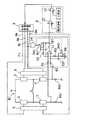
図1は、本発明の第1の実施形態に係るインダクタンス負荷制御装置を示すブロック図である。
このインダクタンス負荷制御装置は、インダクタンス負荷であるモータ(例えば、ステッピングモータ)の巻線Lに駆動電流を流すためのH型ブリッジ回路BCを備えている。
H型ブリッジ回路BCは、電源の正極と負極(グラウンド)間に直列接続されたスイッチング素子1,3および上記正極と負極間に直列接続されたスイッチング素子2,4を備え、スイッチング素子1,3の共通接続点およびスイッチング素子2,4の共通接続点に上記巻線Lの一端および他端がそれぞれ接続されている。
なお、スイッチング素子1〜4には、電界効果トランジスタ等が使用される。また、スイッチング素子1〜4には、図示していないフリーホイールダイオードがそれぞれ並列接続されている。FIG. 1 is a block diagram showing an inductance load control device according to the first embodiment of the present invention.
This inductance load control device includes an H-type bridge circuit BC for causing a drive current to flow through a winding L of a motor (for example, a stepping motor) that is an inductance load.
The H-type bridge circuit BC includes
In addition, a field effect transistor etc. are used for the switching elements 1-4. In addition, free wheel diodes (not shown) are connected in parallel to the
このモータ駆動装置は、更に、H型ブリッジ回路BCのローサイドのスイッチング素子3および4とグラウンドとの間にそれぞれ介在させた電流検出用抵抗器Rs1およびRs2と、スイッチング素子1,3にオンオフ信号を出力する駆動回路5と、スイッチング素子2,4にオンオフ信号を出力する駆動回路6と、上記電流検出用抵抗器Rs1,Rs2に接続された差動増幅部7−1と、該差動増幅部7−1の出力に接続された電流制御部8と、該電流制御部8の出力に接続され、所定のスイッチングシーケンスに従ったオンオフ制御信号を駆動回路5,6に出力する制御信号生成部9とを備えている。 The motor drive device further supplies current detection resistors Rs1 and Rs2 interposed between the low-
上記差動増幅部7−1は、演算増幅器11を用いた加算器としての構成を有し、上記電流検出用抵抗器Rs1,Rs2に生じる電圧に基づいてモータ電流に対応する電圧を発生する手段、つまり、電流検出手段として設けられている。上記演算増幅器11は、その反転入力が入力抵抗器R1を介して電流検出用抵抗器Rs1の非グラウンド側端に接続され、その非反転入力が入力抵抗器R2を介して電流検出用抵抗器Rs2の非グラウンド側端に接続されている。また、演算増幅器11は、その反転入力と出力間に、直列接続された帰還抵抗器R3,R4およびフィルタ用キャパシタCp1が介在され、その非反転入力とグラウンド間に、直列接続された帰還抵抗器R5,R6およびフィルタ用キャパシタCp2が介在されている。そして、帰還抵抗器R4およびR6には、それぞれゲイン切換用のアナログスイッチSw1およびSw2が並列接続されている。
なお、本実施形態では、電流検出用抵抗器Rs1,Rs2として抵抗値が等しいものを使用し、また、上記入力抵抗器R1およびR2の抵抗値r1およびr2をr1=r2に設定するともに、上記帰還抵抗器R3,R4,R5およびR6の抵抗値r3,r4,r5およびr6をr3=r4=r5=r6に設定している。The differential amplifier 7-1 has a configuration as an adder using the
In the present embodiment, resistors having the same resistance value are used as the current detection resistors Rs1 and Rs2, and the resistance values r1 and r2 of the input resistors R1 and R2 are set to r1 = r2. The resistance values r3, r4, r5 and r6 of the feedback resistors R3, R4, R5 and R6 are set to r3 = r4 = r5 = r6.
以下、本実施形態に係るインダクタンス負荷制御装置の動作について説明する。
制御信号生成部9は、スイッチング素子2,3(あるいは、スイッチング素子1,4)をオンさせる「Fastモード」とスイッチング素子3,4をオンさせる「Slowモード」とを順次切換えるスイッチングシーケンスを実行する。
上記「Fastモード」では、制御信号生成部9からライン8bおよびライン8dのみにオン制御信号が出力されるので、駆動回路5,6を介してスイッチング素子2,3が同時にオンされ、その結果、図2に実線矢印で示すモータ電流(駆動電流)が流れる。
そして、上記「Slowモード」では、制御信号生成部9からライン8cおよびライン8dのみにオン制御信号が出力されるので、駆動回路5,6を介してスイッチング素子3,4が同時にオンされ、その結果、図3に実線矢印で示すモータ電流(還流電流)が流れる。このモータ電流は、「Fastモード」時に巻線Lに蓄積されたエネルギーに基づくものである。Hereinafter, the operation of the inductance load control device according to the present embodiment will be described.
The control
In the “Fast mode”, an ON control signal is output from the
In the “Slow mode”, the
ところで、図3に実線矢印で示す還流電流は、スイッチング素子3、およびスイッチング素子4に並列接続された前記フリーホイールダイオードを通って流れる。したがって、上記還流電流は、スイッチング素子4をオンさせない状態でも流れることになるが、還流電流路の内部抵抗をより小さくするためは、該スイッチング素子4をオンさせることが望ましい。そこで、本実施形態では、上記「Slowモード」時に、スイッチング素子3,4の双方をオンさせるようにしている。
なお、スイッチング素子1,4をオンさせる「Fastモード」では、図2に点線矢印で示すモータ電流が流れる。そして、この場合、「Slowモード」で図3に点線矢印で示すモータ電流(還流電流)が流れることになる。By the way, the return current indicated by the solid arrow in FIG. 3 flows through the switching
In the “Fast mode” in which the
スイッチング素子2,3をオンさせる「Fastモード」では、モータ電流(駆動電流)に対応する電圧が一方の電流検出用抵抗器Rs1の両端に発生する。そして、シーケンスが上記「Slowモード」に移行すると、モータ電流(還流電流)に対応する電圧が電流検出用抵抗器Rs1の両端および電流検出用抵抗器Rs2の両端にそれぞれ発生する。 In the “Fast mode” in which the
ここで、電流検出用抵抗器Rs1の端子電圧をV1、電流検出用抵抗器Rs2の端子電圧をV2とし、前記スイッチSw1およびSw2が共に図1に示す状態にあるとすると、つまり、演算増幅器11のゲインが固定されているとすると、該演算増幅器11の出力電圧V0は以下のように表される。
V0=−[(r3+r4)/r1]×(V1−V2)
したがって、V2=0である「Fastモード」での演算増幅器11の出力電圧V0は、
V0=−[(r3+r4)/r1]×V1
と表され、また、V2=−V1である「slowモード」での演算増幅器11の出力電圧V0は、
V0=−2×[(r3+r4)/r1]×V1
と表される。Here, assuming that the terminal voltage of the current detection resistor Rs1 is V1 , the terminal voltage of the current detection resistor Rs2 is V2 , and the switches Sw1 and Sw2 are both in the state shown in FIG. Assuming that the gain of the
V0 = − [(r3 + r4) / r1] × (V1 −V2 )
Therefore, the output voltage V0 of the
V0 = − [(r3 + r4) / r1] × V1
And the output voltage V0 of the
V0 = −2 × [(r3 + r4) / r1] × V1
It is expressed.
以上から明らかなように、演算増幅器11のゲインが固定されている場合、「Fastモード」と「slowモード」とでモータ電流と演算増幅器11の出力電圧V0との対応関係が相違することになる。つまり、本実施形態では、例えば、「Fastモード」と「slowモード」におけるモータ電流が等しいとすると、後者における演算増幅器11の出力電圧V0が前者のそれの2倍になる。換言すれば、「Slowモード」における差動増幅部7−1の電流検出レベルが「Fastモード」時におけるそれの2倍になる。As is apparent from the above, when the gain of the
図4の上段には、上記「Fastモード」時および「Slowモード」における演算増幅器11の出力電圧波形aが例示されている。この図4から明らかなように、「Slowモード」では、演算増幅器11の出力電圧が点線で示す正規の値の2倍の値を示している。これは、上記電流検出レベルの倍増に基づくものである。 The upper part of FIG. 4 illustrates the output voltage waveform a of the
「Slowモード」時の差動増幅部7−1の電流検出レベルを「Fastモード」時のそれと一致させるには、「Slowモード」時の演算増幅器11のゲインを「Fastモード」時のそれの1/2に設定すればよい。
「Slowモード」では、スイッチング素子3,4をオンさせるために、制御信号生成部9が出力ライン8c、8dに論理レベル「H」の信号を出力する。差動増幅部7−1に組込まれたアンド回路14は、ライン8c、8dにその各入力が接続されているので、「Slowモード」時にアナログスイッチSw1およびSw2を同時に切換接続する。このため、「Slowモード」時においては、抵抗器R4およびR6が共に短絡されて、演算増幅器11のゲインがr3/r1、つまり、「Fastモード」時のゲインの1/2になる。
かくして、この実施形態によれば、「Slowモード」時の差動増幅部7−1の電流検出レベルと「Fastモード」時のそれとが一致し、その結果、図4の下段に示す波形bから明らかなように、「Slowモード」時に演算増幅器11が還流電流の大きさに対応する正しい電圧を出力することになる。In order to make the current detection level of the differential amplifier 7-1 in the “Slow mode” coincide with that in the “Fast mode”, the gain of the
In the “Slow mode”, the
Thus, according to this embodiment, the current detection level of the differential amplifier 7-1 in the “Slow mode” matches that in the “Fast mode”, and as a result, from the waveform b shown in the lower part of FIG. As is apparent, the
なお、「Fastモード」と「Slowモード」の切換時や、スイッチSw1およびSw2による演算増幅器11のゲインの切換時には、演算増幅器11の出力にサージの影響が現れるおそれがある。図1に示すキャパシタCp1およびCp2は、このサージを抑制するためのローパスフィルタとして設けたものである。 When switching between the “Fast mode” and the “Slow mode” or when switching the gain of the
モータ電流に対応する差動増幅部7−1の出力は、電流制御部8の減算器12に入力される。減算器12は、電流指令(目標電流を示す電圧)と差動増幅部7−1の出力との偏差(電流偏差)を演算し、その偏差を比較器13に出力する。そこで、比較器13は、図示していない三角波発生器から与えられる三角波と上記偏差とを比較して、該偏差に対応するPWM(パルス幅変調)信号を形成する。そして、前記制御信号生成部9は、上記PWM信号に基づいて上記「Fastモード」および「Slowモード」を規定し、これらのモードに応じてH型ブリッジ回路BCのスイッチング素子1〜4を選択的にオンオフ制御する。 The output of the differential amplifier 7-1 corresponding to the motor current is input to the
上記したように、本実施形態に係るインダクタンス負荷制御装置によれば、「Slowモード」時の差動増幅部7−1の電流検出レベルと「Fastモード」時のそれとを一致させることができる。したがって、「Fastモード」および「Slowモード」におけるモータ電流を連続的に検出して、該モータ電流を適正に制御することが可能なる。 As described above, according to the inductance load control device of the present embodiment, the current detection level of the differential amplifying unit 7-1 in the “Slow mode” can be matched with that in the “Fast mode”. Accordingly, it is possible to continuously detect the motor current in the “Fast mode” and the “Slow mode” and control the motor current appropriately.
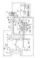
図5は、本発明の第2の実施形態に係るインダクタンス負荷制御装置を示している。
本実施形態に係るインダクタンス負荷制御装置は、差動増幅部7−2の構成において前記第1の実施形態と相違する。
すなわち、本実施形態に係る差動増幅部7−2は、帰還抵抗器R3を演算増幅器11の反転入力と出力間に介在させた点と、該反転入力と出力間に帰還抵抗器R4とゲイン切換用スイッチSw1を直列に介在させた点と、上記非反転入力とグラウンド間に帰還抵抗器R5を介在させた点と、該非反転入力とグラウンド間に帰還抵抗器R6とゲイン切換用スイッチSw2を直列に介在させた点とにおいて図1に示す差動増幅部7−1と相違する。FIG. 5 shows an inductance load control apparatus according to the second embodiment of the present invention.
The inductance load control apparatus according to the present embodiment is different from the first embodiment in the configuration of the differential amplifier 7-2.
That is, the differential amplifying unit 7-2 according to the present embodiment has a point that the feedback resistor R3 is interposed between the inverting input and the output of the
この差動増幅部7−2において、スイッチSw1、Sw2が図示の接続状態にある「Fastモード」時には、演算増幅器11のゲインがr3/r1であるが、スイッチSw1、Sw2が切換接続される「Slowモード」時には、抵抗器R3に抵抗器R4が並列接続されるとともに、抵抗器R6に抵抗器R5が並列接続されることから、演算増幅器11の帰還抵抗値が半減され、その結果、そのゲインが(r3/2)/r1、つまり、「Fastモード」時のゲインの1/2になる。
したがって、本実施形態に係るインダクタンス負荷制御装置においても、「Slowモード」時の差動増幅部7−2の電流検出レベルと「Fastモード」時のそれとを一致させることができる。In the differential amplifier 7-2, when the switches Sw1 and Sw2 are in the illustrated connection state in the “Fast mode”, the gain of the
Therefore, also in the inductance load control device according to the present embodiment, the current detection level of the differential amplifying unit 7-2 in the “Slow mode” can be matched with that in the “Fast mode”.
図6は、本発明の第3の実施形態に係るインダクタンス負荷制御装置を示している。
本実施形態に係るインダクタンス負荷制御装置は、差動増幅部7−3の構成において前記第2の実施形態と相違する。
すなわち、図6に示す差動増幅部7−3は、入力抵抗器R4をゲイン切換用スイッチSw1を介して入力抵抗器R1に並列接続した点と、入力抵抗器R6をゲイン切換用スイッチSw2を介して入力抵抗器R2に並列接続した点とにおいて図5に示す差動増幅部7−2と相違する。FIG. 6 shows an inductance load control apparatus according to the third embodiment of the present invention.
The inductance load control device according to the present embodiment is different from the second embodiment in the configuration of the differential amplifier 7-3.
That is, the differential amplifying unit 7-3 shown in FIG. 6 includes a point where the input resistor R4 is connected in parallel to the input resistor R1 via the gain switching switch Sw1, and the input resistor R6 is connected to the gain switching switch Sw2. 5 is different from the differential amplifier 7-2 shown in FIG. 5 in that it is connected in parallel to the input resistor R2.
この差動増幅部7−3において、スイッチSw1、Sw2が図示の接続状態にある「Fastモード」時には、抵抗器R4が抵抗器R1に並列接続されるとともに、抵抗器R6が抵抗器R2に並列接続されるので、演算増幅器11のゲインがr3/(r1/2)であるが、スイッチSw1、Sw2が切換接続される「Slowモード」時には、演算増幅器11の入力抵抗値が倍増されるので、そのゲインがr3/r1、つまり、「Fastモード」時のゲインの1/2になる。
したがって、本実施形態に係るインダクタンス負荷制御装置においても、「Slowモード」時の差動増幅部7−2の電流検出レベルと「Fastモード」時のそれとを一致させることができる。In the differential amplifier 7-3, when the switches Sw1 and Sw2 are in the illustrated connection state in the “Fast mode”, the resistor R4 is connected in parallel to the resistor R1, and the resistor R6 is connected in parallel to the resistor R2. Since the gain of the
Therefore, also in the inductance load control device according to the present embodiment, the current detection level of the differential amplifying unit 7-2 in the “Slow mode” can be matched with that in the “Fast mode”.
図7は、本発明の第4の実施形態に係るインダクタンス負荷制御装置を示している。
本実施形態に係るインダクタンス負荷制御装置は、差動増幅部7−4の構成において前記第3の実施形態と相違する。
すなわち、図7に示す差動増幅部7−4は、抵抗器R4を抵抗器R1に直列接続した点と、ゲイン切換用スイッチSw1を抵抗器R4に並列接続した点と、抵抗器R6を抵抗器R2に直列接続した点と、ゲイン切換用スイッチSw2を抵抗器R6に並列接続した点とにおいて図6に示す差動増幅部7−3と相違する。FIG. 7 shows an inductance load control apparatus according to the fourth embodiment of the present invention.
The inductance load control device according to the present embodiment is different from the third embodiment in the configuration of the differential amplifier 7-4.
That is, the differential amplifying unit 7-4 shown in FIG. 7 includes a resistor R4 connected in series to the resistor R1, a gain switching switch Sw1 connected in parallel to the resistor R4, and a resistor R6. 6 is different from the differential amplifier 7-3 shown in FIG. 6 in that it is connected in series to the resistor R2 and in that a gain switching switch Sw2 is connected in parallel to the resistor R6.
この差動増幅部7−4において、スイッチSw1、Sw2が図示の接続状態にある「Fastモード」時には、抵抗器R4およびR6が共に短絡されることから、演算増幅器11のゲインがr3/r1であるが、スイッチSw1、Sw2が切換接続される「Slowモード」時には、抵抗器R4が抵抗器R1に直列接続されるとともに、抵抗器R6が抵抗器R2に直列接続されるので、演算増幅器11の入力抵抗値が倍増され、その結果、そのゲインがr3/(2r1)、つまり、「Fastモード」時のゲインの1/2になる。
したがって、本実施形態に係るインダクタンス負荷制御装置においても、「Slowモード」時の差動増幅部7−2の電流検出レベルと「Fastモード」時のそれとを一致させることができる。In the differential amplifier 7-4, when the switches Sw1 and Sw2 are in the illustrated connection state in the “Fast mode”, the resistors R4 and R6 are short-circuited together, so that the gain of the
Therefore, also in the inductance load control device according to the present embodiment, the current detection level of the differential amplifying unit 7-2 in the “Slow mode” can be matched with that in the “Fast mode”.
上述した各実施形態に係るインダクタンス負荷制御装置は、高価な電流検出手段を使用する必要がなく、しかも、電流のリプルを小さくすることが可能なスイッチングシーケンスを採用して、モータの巻線等のインダクタンス負荷に流れる電流を連続的かつ精度よく検出することができるので実用性が高い。 The inductance load control device according to each of the above-described embodiments does not need to use an expensive current detection unit, and adopts a switching sequence that can reduce the current ripple, such as a motor winding. Since the current flowing through the inductance load can be detected continuously and accurately, it is highly practical.
なお、上記各実施形態では、電流検出用抵抗器Rs1,Rs2として抵抗値が等しいものを使用している。しかし、本発明は、この電流検出用抵抗器Rs1,Rs2として抵抗値の異なるものを使用する場合でも実施可能である。
また、本発明は、インダクタンス負荷がモータの巻線Lではない場合にも適用可能である。In each of the above embodiments, the resistors having the same resistance value are used as the current detection resistors Rs1 and Rs2. However, the present invention can be implemented even when the current detection resistors Rs1 and Rs2 have different resistance values.
The present invention is also applicable when the inductance load is not the winding L of the motor.
1〜4 スイッチング素子
Rs1,Rs2 電流検出用抵抗器
L モータ巻線
5,6 駆動回路
R1〜R6 抵抗器
7−1〜7−4 差動増幅部
Cp1,Cp2 キャパシタ
Sw1,Sw2 スイッチ
8 電流制御部
9 制御信号生成部
10 電流検出方向生成部
11 演算増幅器
14 アンド回路1-4 Switching elements Rs1, Rs2 Current detection resistors
Claims (8)
Translated fromJapanese前記Hブリッジ回路における一方のローサイドスイッチング素子とグラウンド間に介在させた第1の電流検出抵抗器と、
前記Hブリッジ回路における他方のローサイドスイッチング素子とグラウンド間に介在させた第2の電流検出抵抗器と、
前記第1、第2の電流検出抵抗器の端子電圧に基づいて、前記インダクタンス負荷に流れる電流を検出する電流検出手段と、
前記インダクタンス負荷に流れる電流に基づいてPWM信号を形成するPWM信号形成手段と、
前記PWM信号に基づいて、前記Hブリッジ回路における対角の各スイッチング素子を介して前記負荷に駆動電流を流す第1のモードと、前記Hブリッジ回路におけるローサイドのスイッチング素子を介して前記負荷に放電電流を流す第2のモードとを切換えるスイッチングシーケンスを実行するシーケンス制御手段と、
を備え、前記電流検出手段は、
前記第1、第2の電流検出抵抗器の端子電圧を差動増幅する差動増幅手段と、
前記駆動電流と前記差動増幅手段の出力との対応関係と前記放電電流と前記差動増幅手段の出力との対応関係が一致するように、前記第2のモード時に前記差動増幅手段のゲインを前記第1のモード時のゲインよりも低下させるゲイン調整手段と、
を備えることを特徴とするインダクタンス負荷制御装置。An H-bridge circuit having a switching element connected in a bridge, and passing a current to an inductance load via the switching element;
A first current detection resistor interposed between one low-side switching element and the ground in the H-bridge circuit;
A second current detection resistor interposed between the other low-side switching element and the ground in the H-bridge circuit;
Current detection means for detecting a current flowing through the inductance load based on a terminal voltage of the first and second current detection resistors;
PWM signal forming means for forming a PWM signal based on the current flowing through the inductance load;
Based on the PWM signal, a first mode in which a drive current is passed to the load via each diagonal switching element in the H bridge circuit, and a discharge to the load via the low side switching element in the H bridge circuit Sequence control means for executing a switching sequence for switching between a second mode in which a current flows;
The current detection means comprises
Differential amplification means for differentially amplifying terminal voltages of the first and second current detection resistors;
The gain of the differential amplifying means during the second mode so that the correspondence between the drive current and the output of the differential amplifying means matches the correspondence between the discharge current and the output of thedifferential amplifying means. Gain adjusting means forlowering the gain than the gain in the first mode ;
An inductance load control device comprising:
載のインダクタンス負荷制御装置。The inductance load control device according to claim 1, wherein the first and second current detection resistors have the same resistance value.
4. The inductance load control apparatus according to claim 3, wherein a capacitor having a function as a filter is connected in parallel to the feedback resistor in order to suppress an output surge of the differential amplifier.
Priority Applications (1)
| Application Number | Priority Date | Filing Date | Title |
|---|---|---|---|
| JP2007052961AJP5096020B2 (en) | 2007-03-02 | 2007-03-02 | Inductance load control device |
Applications Claiming Priority (1)
| Application Number | Priority Date | Filing Date | Title |
|---|---|---|---|
| JP2007052961AJP5096020B2 (en) | 2007-03-02 | 2007-03-02 | Inductance load control device |
Publications (2)
| Publication Number | Publication Date |
|---|---|
| JP2008220032A JP2008220032A (en) | 2008-09-18 |
| JP5096020B2true JP5096020B2 (en) | 2012-12-12 |
Family
ID=39839394
Family Applications (1)
| Application Number | Title | Priority Date | Filing Date |
|---|---|---|---|
| JP2007052961AActiveJP5096020B2 (en) | 2007-03-02 | 2007-03-02 | Inductance load control device |
Country Status (1)
| Country | Link |
|---|---|
| JP (1) | JP5096020B2 (en) |
Cited By (2)
| Publication number | Priority date | Publication date | Assignee | Title |
|---|---|---|---|---|
| US11137419B2 (en) | 2019-12-17 | 2021-10-05 | Analog Devices International Unlimited Company | Mutiple range current sensor techniques |
| US11193957B2 (en) | 2019-08-13 | 2021-12-07 | Analog Devices International Unlimited Company | Shunt resistor averaging techniques |
Families Citing this family (422)
| Publication number | Priority date | Publication date | Assignee | Title |
|---|---|---|---|---|
| US20070084897A1 (en) | 2003-05-20 | 2007-04-19 | Shelton Frederick E Iv | Articulating surgical stapling instrument incorporating a two-piece e-beam firing mechanism |
| US9060770B2 (en) | 2003-05-20 | 2015-06-23 | Ethicon Endo-Surgery, Inc. | Robotically-driven surgical instrument with E-beam driver |
| US8215531B2 (en) | 2004-07-28 | 2012-07-10 | Ethicon Endo-Surgery, Inc. | Surgical stapling instrument having a medical substance dispenser |
| US11998198B2 (en) | 2004-07-28 | 2024-06-04 | Cilag Gmbh International | Surgical stapling instrument incorporating a two-piece E-beam firing mechanism |
| US11890012B2 (en) | 2004-07-28 | 2024-02-06 | Cilag Gmbh International | Staple cartridge comprising cartridge body and attached support |
| US9072535B2 (en) | 2011-05-27 | 2015-07-07 | Ethicon Endo-Surgery, Inc. | Surgical stapling instruments with rotatable staple deployment arrangements |
| US10159482B2 (en) | 2005-08-31 | 2018-12-25 | Ethicon Llc | Fastener cartridge assembly comprising a fixed anvil and different staple heights |
| US7934630B2 (en) | 2005-08-31 | 2011-05-03 | Ethicon Endo-Surgery, Inc. | Staple cartridges for forming staples having differing formed staple heights |
| US9237891B2 (en) | 2005-08-31 | 2016-01-19 | Ethicon Endo-Surgery, Inc. | Robotically-controlled surgical stapling devices that produce formed staples having different lengths |
| US11246590B2 (en) | 2005-08-31 | 2022-02-15 | Cilag Gmbh International | Staple cartridge including staple drivers having different unfired heights |
| US7669746B2 (en) | 2005-08-31 | 2010-03-02 | Ethicon Endo-Surgery, Inc. | Staple cartridges for forming staples having differing formed staple heights |
| US11484312B2 (en) | 2005-08-31 | 2022-11-01 | Cilag Gmbh International | Staple cartridge comprising a staple driver arrangement |
| US20070106317A1 (en) | 2005-11-09 | 2007-05-10 | Shelton Frederick E Iv | Hydraulically and electrically actuated articulation joints for surgical instruments |
| US8186555B2 (en) | 2006-01-31 | 2012-05-29 | Ethicon Endo-Surgery, Inc. | Motor-driven surgical cutting and fastening instrument with mechanical closure system |
| US7753904B2 (en) | 2006-01-31 | 2010-07-13 | Ethicon Endo-Surgery, Inc. | Endoscopic surgical instrument with a handle that can articulate with respect to the shaft |
| US11278279B2 (en) | 2006-01-31 | 2022-03-22 | Cilag Gmbh International | Surgical instrument assembly |
| US20120292367A1 (en) | 2006-01-31 | 2012-11-22 | Ethicon Endo-Surgery, Inc. | Robotically-controlled end effector |
| US11224427B2 (en) | 2006-01-31 | 2022-01-18 | Cilag Gmbh International | Surgical stapling system including a console and retraction assembly |
| US20110024477A1 (en) | 2009-02-06 | 2011-02-03 | Hall Steven G | Driven Surgical Stapler Improvements |
| US11793518B2 (en) | 2006-01-31 | 2023-10-24 | Cilag Gmbh International | Powered surgical instruments with firing system lockout arrangements |
| US20110295295A1 (en) | 2006-01-31 | 2011-12-01 | Ethicon Endo-Surgery, Inc. | Robotically-controlled surgical instrument having recording capabilities |
| US8708213B2 (en) | 2006-01-31 | 2014-04-29 | Ethicon Endo-Surgery, Inc. | Surgical instrument having a feedback system |
| US8820603B2 (en) | 2006-01-31 | 2014-09-02 | Ethicon Endo-Surgery, Inc. | Accessing data stored in a memory of a surgical instrument |
| US7845537B2 (en) | 2006-01-31 | 2010-12-07 | Ethicon Endo-Surgery, Inc. | Surgical instrument having recording capabilities |
| US8992422B2 (en) | 2006-03-23 | 2015-03-31 | Ethicon Endo-Surgery, Inc. | Robotically-controlled endoscopic accessory channel |
| US8322455B2 (en) | 2006-06-27 | 2012-12-04 | Ethicon Endo-Surgery, Inc. | Manually driven surgical cutting and fastening instrument |
| US7506791B2 (en) | 2006-09-29 | 2009-03-24 | Ethicon Endo-Surgery, Inc. | Surgical stapling instrument with mechanical mechanism for limiting maximum tissue compression |
| US10568652B2 (en) | 2006-09-29 | 2020-02-25 | Ethicon Llc | Surgical staples having attached drivers of different heights and stapling instruments for deploying the same |
| US11980366B2 (en) | 2006-10-03 | 2024-05-14 | Cilag Gmbh International | Surgical instrument |
| US8684253B2 (en) | 2007-01-10 | 2014-04-01 | Ethicon Endo-Surgery, Inc. | Surgical instrument with wireless communication between a control unit of a robotic system and remote sensor |
| US8632535B2 (en) | 2007-01-10 | 2014-01-21 | Ethicon Endo-Surgery, Inc. | Interlock and surgical instrument including same |
| US8652120B2 (en) | 2007-01-10 | 2014-02-18 | Ethicon Endo-Surgery, Inc. | Surgical instrument with wireless communication between control unit and sensor transponders |
| US11291441B2 (en) | 2007-01-10 | 2022-04-05 | Cilag Gmbh International | Surgical instrument with wireless communication between control unit and remote sensor |
| US11039836B2 (en) | 2007-01-11 | 2021-06-22 | Cilag Gmbh International | Staple cartridge for use with a surgical stapling instrument |
| US20080169333A1 (en) | 2007-01-11 | 2008-07-17 | Shelton Frederick E | Surgical stapler end effector with tapered distal end |
| US7673782B2 (en) | 2007-03-15 | 2010-03-09 | Ethicon Endo-Surgery, Inc. | Surgical stapling instrument having a releasable buttress material |
| US8893946B2 (en) | 2007-03-28 | 2014-11-25 | Ethicon Endo-Surgery, Inc. | Laparoscopic tissue thickness and clamp load measuring devices |
| US8931682B2 (en) | 2007-06-04 | 2015-01-13 | Ethicon Endo-Surgery, Inc. | Robotically-controlled shaft based rotary drive systems for surgical instruments |
| US11564682B2 (en) | 2007-06-04 | 2023-01-31 | Cilag Gmbh International | Surgical stapler device |
| US7753245B2 (en) | 2007-06-22 | 2010-07-13 | Ethicon Endo-Surgery, Inc. | Surgical stapling instruments |
| US11849941B2 (en) | 2007-06-29 | 2023-12-26 | Cilag Gmbh International | Staple cartridge having staple cavities extending at a transverse angle relative to a longitudinal cartridge axis |
| US8636736B2 (en) | 2008-02-14 | 2014-01-28 | Ethicon Endo-Surgery, Inc. | Motorized surgical cutting and fastening instrument |
| JP5410110B2 (en) | 2008-02-14 | 2014-02-05 | エシコン・エンド−サージェリィ・インコーポレイテッド | Surgical cutting / fixing instrument with RF electrode |
| US8573465B2 (en) | 2008-02-14 | 2013-11-05 | Ethicon Endo-Surgery, Inc. | Robotically-controlled surgical end effector system with rotary actuated closure systems |
| US11986183B2 (en) | 2008-02-14 | 2024-05-21 | Cilag Gmbh International | Surgical cutting and fastening instrument comprising a plurality of sensors to measure an electrical parameter |
| US7819298B2 (en) | 2008-02-14 | 2010-10-26 | Ethicon Endo-Surgery, Inc. | Surgical stapling apparatus with control features operable with one hand |
| US7866527B2 (en) | 2008-02-14 | 2011-01-11 | Ethicon Endo-Surgery, Inc. | Surgical stapling apparatus with interlockable firing system |
| US8758391B2 (en) | 2008-02-14 | 2014-06-24 | Ethicon Endo-Surgery, Inc. | Interchangeable tools for surgical instruments |
| US9179912B2 (en) | 2008-02-14 | 2015-11-10 | Ethicon Endo-Surgery, Inc. | Robotically-controlled motorized surgical cutting and fastening instrument |
| US9585657B2 (en) | 2008-02-15 | 2017-03-07 | Ethicon Endo-Surgery, Llc | Actuator for releasing a layer of material from a surgical end effector |
| US11272927B2 (en) | 2008-02-15 | 2022-03-15 | Cilag Gmbh International | Layer arrangements for surgical staple cartridges |
| US11648005B2 (en) | 2008-09-23 | 2023-05-16 | Cilag Gmbh International | Robotically-controlled motorized surgical instrument with an end effector |
| US9005230B2 (en) | 2008-09-23 | 2015-04-14 | Ethicon Endo-Surgery, Inc. | Motorized surgical instrument |
| US8210411B2 (en) | 2008-09-23 | 2012-07-03 | Ethicon Endo-Surgery, Inc. | Motor-driven surgical cutting instrument |
| US9386983B2 (en) | 2008-09-23 | 2016-07-12 | Ethicon Endo-Surgery, Llc | Robotically-controlled motorized surgical instrument |
| US8608045B2 (en) | 2008-10-10 | 2013-12-17 | Ethicon Endo-Sugery, Inc. | Powered surgical cutting and stapling apparatus with manually retractable firing system |
| US8517239B2 (en) | 2009-02-05 | 2013-08-27 | Ethicon Endo-Surgery, Inc. | Surgical stapling instrument comprising a magnetic element driver |
| RU2525225C2 (en) | 2009-02-06 | 2014-08-10 | Этикон Эндо-Серджери, Инк. | Improvement of drive surgical suturing instrument |
| US8444036B2 (en) | 2009-02-06 | 2013-05-21 | Ethicon Endo-Surgery, Inc. | Motor driven surgical fastener device with mechanisms for adjusting a tissue gap within the end effector |
| US8220688B2 (en) | 2009-12-24 | 2012-07-17 | Ethicon Endo-Surgery, Inc. | Motor-driven surgical cutting instrument with electric actuator directional control assembly |
| US8851354B2 (en) | 2009-12-24 | 2014-10-07 | Ethicon Endo-Surgery, Inc. | Surgical cutting instrument that analyzes tissue thickness |
| JP5655367B2 (en)* | 2010-05-07 | 2015-01-21 | パナソニックIpマネジメント株式会社 | Motor drive device |
| US8783543B2 (en) | 2010-07-30 | 2014-07-22 | Ethicon Endo-Surgery, Inc. | Tissue acquisition arrangements and methods for surgical stapling devices |
| US11812965B2 (en) | 2010-09-30 | 2023-11-14 | Cilag Gmbh International | Layer of material for a surgical end effector |
| US9351730B2 (en) | 2011-04-29 | 2016-05-31 | Ethicon Endo-Surgery, Llc | Tissue thickness compensator comprising channels |
| US12213666B2 (en) | 2010-09-30 | 2025-02-04 | Cilag Gmbh International | Tissue thickness compensator comprising layers |
| US11925354B2 (en) | 2010-09-30 | 2024-03-12 | Cilag Gmbh International | Staple cartridge comprising staples positioned within a compressible portion thereof |
| US10945731B2 (en) | 2010-09-30 | 2021-03-16 | Ethicon Llc | Tissue thickness compensator comprising controlled release and expansion |
| US11298125B2 (en) | 2010-09-30 | 2022-04-12 | Cilag Gmbh International | Tissue stapler having a thickness compensator |
| US9016542B2 (en) | 2010-09-30 | 2015-04-28 | Ethicon Endo-Surgery, Inc. | Staple cartridge comprising compressible distortion resistant components |
| US9629814B2 (en) | 2010-09-30 | 2017-04-25 | Ethicon Endo-Surgery, Llc | Tissue thickness compensator configured to redistribute compressive forces |
| US9364233B2 (en) | 2010-09-30 | 2016-06-14 | Ethicon Endo-Surgery, Llc | Tissue thickness compensators for circular surgical staplers |
| US9232941B2 (en) | 2010-09-30 | 2016-01-12 | Ethicon Endo-Surgery, Inc. | Tissue thickness compensator comprising a reservoir |
| US9788834B2 (en) | 2010-09-30 | 2017-10-17 | Ethicon Llc | Layer comprising deployable attachment members |
| US9386988B2 (en) | 2010-09-30 | 2016-07-12 | Ethicon End-Surgery, LLC | Retainer assembly including a tissue thickness compensator |
| US8695866B2 (en) | 2010-10-01 | 2014-04-15 | Ethicon Endo-Surgery, Inc. | Surgical instrument having a power control circuit |
| AU2012250197B2 (en) | 2011-04-29 | 2017-08-10 | Ethicon Endo-Surgery, Inc. | Staple cartridge comprising staples positioned within a compressible portion thereof |
| US11207064B2 (en) | 2011-05-27 | 2021-12-28 | Cilag Gmbh International | Automated end effector component reloading system for use with a robotic system |
| US9044230B2 (en) | 2012-02-13 | 2015-06-02 | Ethicon Endo-Surgery, Inc. | Surgical cutting and fastening instrument with apparatus for determining cartridge and firing motion status |
| BR112014024098B1 (en) | 2012-03-28 | 2021-05-25 | Ethicon Endo-Surgery, Inc. | staple cartridge |
| MX358135B (en) | 2012-03-28 | 2018-08-06 | Ethicon Endo Surgery Inc | Tissue thickness compensator comprising a plurality of layers. |
| JP6224070B2 (en) | 2012-03-28 | 2017-11-01 | エシコン・エンド−サージェリィ・インコーポレイテッドEthicon Endo−Surgery,Inc. | Retainer assembly including tissue thickness compensator |
| US9101358B2 (en) | 2012-06-15 | 2015-08-11 | Ethicon Endo-Surgery, Inc. | Articulatable surgical instrument comprising a firing drive |
| US20140001231A1 (en) | 2012-06-28 | 2014-01-02 | Ethicon Endo-Surgery, Inc. | Firing system lockout arrangements for surgical instruments |
| JP6290201B2 (en) | 2012-06-28 | 2018-03-07 | エシコン・エンド−サージェリィ・インコーポレイテッドEthicon Endo−Surgery,Inc. | Lockout for empty clip cartridge |
| US12383267B2 (en) | 2012-06-28 | 2025-08-12 | Cilag Gmbh International | Robotically powered surgical device with manually-actuatable reversing system |
| US9282974B2 (en) | 2012-06-28 | 2016-03-15 | Ethicon Endo-Surgery, Llc | Empty clip cartridge lockout |
| US9408606B2 (en) | 2012-06-28 | 2016-08-09 | Ethicon Endo-Surgery, Llc | Robotically powered surgical device with manually-actuatable reversing system |
| BR112014032776B1 (en) | 2012-06-28 | 2021-09-08 | Ethicon Endo-Surgery, Inc | SURGICAL INSTRUMENT SYSTEM AND SURGICAL KIT FOR USE WITH A SURGICAL INSTRUMENT SYSTEM |
| US9289256B2 (en) | 2012-06-28 | 2016-03-22 | Ethicon Endo-Surgery, Llc | Surgical end effectors having angled tissue-contacting surfaces |
| US20140005718A1 (en) | 2012-06-28 | 2014-01-02 | Ethicon Endo-Surgery, Inc. | Multi-functional powered surgical device with external dissection features |
| US11278284B2 (en) | 2012-06-28 | 2022-03-22 | Cilag Gmbh International | Rotary drive arrangements for surgical instruments |
| RU2672520C2 (en) | 2013-03-01 | 2018-11-15 | Этикон Эндо-Серджери, Инк. | Hingedly turnable surgical instruments with conducting ways for signal transfer |
| BR112015021082B1 (en) | 2013-03-01 | 2022-05-10 | Ethicon Endo-Surgery, Inc | surgical instrument |
| US9629629B2 (en) | 2013-03-14 | 2017-04-25 | Ethicon Endo-Surgey, LLC | Control systems for surgical instruments |
| US9808244B2 (en) | 2013-03-14 | 2017-11-07 | Ethicon Llc | Sensor arrangements for absolute positioning system for surgical instruments |
| US9826976B2 (en) | 2013-04-16 | 2017-11-28 | Ethicon Llc | Motor driven surgical instruments with lockable dual drive shafts |
| BR112015026109B1 (en) | 2013-04-16 | 2022-02-22 | Ethicon Endo-Surgery, Inc | surgical instrument |
| MX369362B (en) | 2013-08-23 | 2019-11-06 | Ethicon Endo Surgery Llc | Firing member retraction devices for powered surgical instruments. |
| US9775609B2 (en) | 2013-08-23 | 2017-10-03 | Ethicon Llc | Tamper proof circuit for surgical instrument battery pack |
| US9962161B2 (en) | 2014-02-12 | 2018-05-08 | Ethicon Llc | Deliverable surgical instrument |
| JP6462004B2 (en) | 2014-02-24 | 2019-01-30 | エシコン エルエルシー | Fastening system with launcher lockout |
| BR112016021943B1 (en) | 2014-03-26 | 2022-06-14 | Ethicon Endo-Surgery, Llc | SURGICAL INSTRUMENT FOR USE BY AN OPERATOR IN A SURGICAL PROCEDURE |
| US10013049B2 (en) | 2014-03-26 | 2018-07-03 | Ethicon Llc | Power management through sleep options of segmented circuit and wake up control |
| US20150272580A1 (en) | 2014-03-26 | 2015-10-01 | Ethicon Endo-Surgery, Inc. | Verification of number of battery exchanges/procedure count |
| US12232723B2 (en) | 2014-03-26 | 2025-02-25 | Cilag Gmbh International | Systems and methods for controlling a segmented circuit |
| US10004497B2 (en) | 2014-03-26 | 2018-06-26 | Ethicon Llc | Interface systems for use with surgical instruments |
| BR112016023825B1 (en) | 2014-04-16 | 2022-08-02 | Ethicon Endo-Surgery, Llc | STAPLE CARTRIDGE FOR USE WITH A SURGICAL STAPLER AND STAPLE CARTRIDGE FOR USE WITH A SURGICAL INSTRUMENT |
| US20150297225A1 (en) | 2014-04-16 | 2015-10-22 | Ethicon Endo-Surgery, Inc. | Fastener cartridges including extensions having different configurations |
| CN106456176B (en) | 2014-04-16 | 2019-06-28 | 伊西康内外科有限责任公司 | Fastener Cartridge Including Extensions With Different Configurations |
| US10470768B2 (en) | 2014-04-16 | 2019-11-12 | Ethicon Llc | Fastener cartridge including a layer attached thereto |
| US10327764B2 (en) | 2014-09-26 | 2019-06-25 | Ethicon Llc | Method for creating a flexible staple line |
| CN106456159B (en) | 2014-04-16 | 2019-03-08 | 伊西康内外科有限责任公司 | Fastener Cartridge Assembly and Nail Retainer Cover Arrangement |
| US10135242B2 (en) | 2014-09-05 | 2018-11-20 | Ethicon Llc | Smart cartridge wake up operation and data retention |
| BR112017004361B1 (en) | 2014-09-05 | 2023-04-11 | Ethicon Llc | ELECTRONIC SYSTEM FOR A SURGICAL INSTRUMENT |
| US11311294B2 (en) | 2014-09-05 | 2022-04-26 | Cilag Gmbh International | Powered medical device including measurement of closure state of jaws |
| US10105142B2 (en) | 2014-09-18 | 2018-10-23 | Ethicon Llc | Surgical stapler with plurality of cutting elements |
| CN107427300B (en) | 2014-09-26 | 2020-12-04 | 伊西康有限责任公司 | Surgical suture buttresses and auxiliary materials |
| US11523821B2 (en) | 2014-09-26 | 2022-12-13 | Cilag Gmbh International | Method for creating a flexible staple line |
| US10076325B2 (en) | 2014-10-13 | 2018-09-18 | Ethicon Llc | Surgical stapling apparatus comprising a tissue stop |
| US9924944B2 (en) | 2014-10-16 | 2018-03-27 | Ethicon Llc | Staple cartridge comprising an adjunct material |
| US11141153B2 (en) | 2014-10-29 | 2021-10-12 | Cilag Gmbh International | Staple cartridges comprising driver arrangements |
| US10517594B2 (en) | 2014-10-29 | 2019-12-31 | Ethicon Llc | Cartridge assemblies for surgical staplers |
| US9844376B2 (en) | 2014-11-06 | 2017-12-19 | Ethicon Llc | Staple cartridge comprising a releasable adjunct material |
| US10736636B2 (en) | 2014-12-10 | 2020-08-11 | Ethicon Llc | Articulatable surgical instrument system |
| US9844375B2 (en) | 2014-12-18 | 2017-12-19 | Ethicon Llc | Drive arrangements for articulatable surgical instruments |
| US10085748B2 (en) | 2014-12-18 | 2018-10-02 | Ethicon Llc | Locking arrangements for detachable shaft assemblies with articulatable surgical end effectors |
| US9844374B2 (en) | 2014-12-18 | 2017-12-19 | Ethicon Llc | Surgical instrument systems comprising an articulatable end effector and means for adjusting the firing stroke of a firing member |
| US9943309B2 (en) | 2014-12-18 | 2018-04-17 | Ethicon Llc | Surgical instruments with articulatable end effectors and movable firing beam support arrangements |
| US10188385B2 (en) | 2014-12-18 | 2019-01-29 | Ethicon Llc | Surgical instrument system comprising lockable systems |
| US9987000B2 (en) | 2014-12-18 | 2018-06-05 | Ethicon Llc | Surgical instrument assembly comprising a flexible articulation system |
| MX389118B (en) | 2014-12-18 | 2025-03-20 | Ethicon Llc | SURGICAL INSTRUMENT WITH AN ANVIL THAT CAN BE SELECTIVELY MOVED ON A DISCRETE, NON-MOBILE AXIS RELATIVE TO A STAPLE CARTRIDGE. |
| US10180463B2 (en) | 2015-02-27 | 2019-01-15 | Ethicon Llc | Surgical apparatus configured to assess whether a performance parameter of the surgical apparatus is within an acceptable performance band |
| US10159483B2 (en) | 2015-02-27 | 2018-12-25 | Ethicon Llc | Surgical apparatus configured to track an end-of-life parameter |
| US11154301B2 (en) | 2015-02-27 | 2021-10-26 | Cilag Gmbh International | Modular stapling assembly |
| US10245033B2 (en) | 2015-03-06 | 2019-04-02 | Ethicon Llc | Surgical instrument comprising a lockable battery housing |
| US10687806B2 (en) | 2015-03-06 | 2020-06-23 | Ethicon Llc | Adaptive tissue compression techniques to adjust closure rates for multiple tissue types |
| US9993248B2 (en) | 2015-03-06 | 2018-06-12 | Ethicon Endo-Surgery, Llc | Smart sensors with local signal processing |
| US10548504B2 (en) | 2015-03-06 | 2020-02-04 | Ethicon Llc | Overlaid multi sensor radio frequency (RF) electrode system to measure tissue compression |
| JP2020121162A (en) | 2015-03-06 | 2020-08-13 | エシコン エルエルシーEthicon LLC | Time dependent evaluation of sensor data to determine stability element, creep element and viscoelastic element of measurement |
| US9808246B2 (en) | 2015-03-06 | 2017-11-07 | Ethicon Endo-Surgery, Llc | Method of operating a powered surgical instrument |
| US10617412B2 (en) | 2015-03-06 | 2020-04-14 | Ethicon Llc | System for detecting the mis-insertion of a staple cartridge into a surgical stapler |
| US10441279B2 (en) | 2015-03-06 | 2019-10-15 | Ethicon Llc | Multiple level thresholds to modify operation of powered surgical instruments |
| US9924961B2 (en) | 2015-03-06 | 2018-03-27 | Ethicon Endo-Surgery, Llc | Interactive feedback system for powered surgical instruments |
| US9901342B2 (en) | 2015-03-06 | 2018-02-27 | Ethicon Endo-Surgery, Llc | Signal and power communication system positioned on a rotatable shaft |
| US10433844B2 (en) | 2015-03-31 | 2019-10-08 | Ethicon Llc | Surgical instrument with selectively disengageable threaded drive systems |
| US10835249B2 (en) | 2015-08-17 | 2020-11-17 | Ethicon Llc | Implantable layers for a surgical instrument |
| US10980538B2 (en) | 2015-08-26 | 2021-04-20 | Ethicon Llc | Surgical stapling configurations for curved and circular stapling instruments |
| US10105139B2 (en)* | 2015-09-23 | 2018-10-23 | Ethicon Llc | Surgical stapler having downstream current-based motor control |
| US10085751B2 (en)* | 2015-09-23 | 2018-10-02 | Ethicon Llc | Surgical stapler having temperature-based motor control |
| US10238386B2 (en) | 2015-09-23 | 2019-03-26 | Ethicon Llc | Surgical stapler having motor control based on an electrical parameter related to a motor current |
| US10327769B2 (en) | 2015-09-23 | 2019-06-25 | Ethicon Llc | Surgical stapler having motor control based on a drive system component |
| US10363036B2 (en) | 2015-09-23 | 2019-07-30 | Ethicon Llc | Surgical stapler having force-based motor control |
| US10299878B2 (en) | 2015-09-25 | 2019-05-28 | Ethicon Llc | Implantable adjunct systems for determining adjunct skew |
| US10478188B2 (en) | 2015-09-30 | 2019-11-19 | Ethicon Llc | Implantable layer comprising a constricted configuration |
| US11890015B2 (en) | 2015-09-30 | 2024-02-06 | Cilag Gmbh International | Compressible adjunct with crossing spacer fibers |
| US10980539B2 (en) | 2015-09-30 | 2021-04-20 | Ethicon Llc | Implantable adjunct comprising bonded layers |
| US10433846B2 (en) | 2015-09-30 | 2019-10-08 | Ethicon Llc | Compressible adjunct with crossing spacer fibers |
| US10368865B2 (en) | 2015-12-30 | 2019-08-06 | Ethicon Llc | Mechanisms for compensating for drivetrain failure in powered surgical instruments |
| US10265068B2 (en) | 2015-12-30 | 2019-04-23 | Ethicon Llc | Surgical instruments with separable motors and motor control circuits |
| US10292704B2 (en) | 2015-12-30 | 2019-05-21 | Ethicon Llc | Mechanisms for compensating for battery pack failure in powered surgical instruments |
| US10413291B2 (en) | 2016-02-09 | 2019-09-17 | Ethicon Llc | Surgical instrument articulation mechanism with slotted secondary constraint |
| US11213293B2 (en) | 2016-02-09 | 2022-01-04 | Cilag Gmbh International | Articulatable surgical instruments with single articulation link arrangements |
| BR112018016098B1 (en) | 2016-02-09 | 2023-02-23 | Ethicon Llc | SURGICAL INSTRUMENT |
| US10258331B2 (en) | 2016-02-12 | 2019-04-16 | Ethicon Llc | Mechanisms for compensating for drivetrain failure in powered surgical instruments |
| US10448948B2 (en) | 2016-02-12 | 2019-10-22 | Ethicon Llc | Mechanisms for compensating for drivetrain failure in powered surgical instruments |
| US11224426B2 (en) | 2016-02-12 | 2022-01-18 | Cilag Gmbh International | Mechanisms for compensating for drivetrain failure in powered surgical instruments |
| US10413297B2 (en) | 2016-04-01 | 2019-09-17 | Ethicon Llc | Surgical stapling system configured to apply annular rows of staples having different heights |
| US10617413B2 (en) | 2016-04-01 | 2020-04-14 | Ethicon Llc | Closure system arrangements for surgical cutting and stapling devices with separate and distinct firing shafts |
| US10492783B2 (en) | 2016-04-15 | 2019-12-03 | Ethicon, Llc | Surgical instrument with improved stop/start control during a firing motion |
| US10335145B2 (en) | 2016-04-15 | 2019-07-02 | Ethicon Llc | Modular surgical instrument with configurable operating mode |
| US11607239B2 (en) | 2016-04-15 | 2023-03-21 | Cilag Gmbh International | Systems and methods for controlling a surgical stapling and cutting instrument |
| US10828028B2 (en) | 2016-04-15 | 2020-11-10 | Ethicon Llc | Surgical instrument with multiple program responses during a firing motion |
| US10456137B2 (en) | 2016-04-15 | 2019-10-29 | Ethicon Llc | Staple formation detection mechanisms |
| US10357247B2 (en) | 2016-04-15 | 2019-07-23 | Ethicon Llc | Surgical instrument with multiple program responses during a firing motion |
| US11179150B2 (en) | 2016-04-15 | 2021-11-23 | Cilag Gmbh International | Systems and methods for controlling a surgical stapling and cutting instrument |
| US10405859B2 (en) | 2016-04-15 | 2019-09-10 | Ethicon Llc | Surgical instrument with adjustable stop/start control during a firing motion |
| US10426467B2 (en) | 2016-04-15 | 2019-10-01 | Ethicon Llc | Surgical instrument with detection sensors |
| US20170296173A1 (en) | 2016-04-18 | 2017-10-19 | Ethicon Endo-Surgery, Llc | Method for operating a surgical instrument |
| US11317917B2 (en) | 2016-04-18 | 2022-05-03 | Cilag Gmbh International | Surgical stapling system comprising a lockable firing assembly |
| US10363037B2 (en) | 2016-04-18 | 2019-07-30 | Ethicon Llc | Surgical instrument system comprising a magnetic lockout |
| US10500000B2 (en) | 2016-08-16 | 2019-12-10 | Ethicon Llc | Surgical tool with manual control of end effector jaws |
| US10568625B2 (en) | 2016-12-21 | 2020-02-25 | Ethicon Llc | Staple cartridges and arrangements of staples and staple cavities therein |
| US10980536B2 (en) | 2016-12-21 | 2021-04-20 | Ethicon Llc | No-cartridge and spent cartridge lockout arrangements for surgical staplers |
| US10542982B2 (en) | 2016-12-21 | 2020-01-28 | Ethicon Llc | Shaft assembly comprising first and second articulation lockouts |
| US10695055B2 (en) | 2016-12-21 | 2020-06-30 | Ethicon Llc | Firing assembly comprising a lockout |
| JP7010957B2 (en) | 2016-12-21 | 2022-01-26 | エシコン エルエルシー | Shaft assembly with lockout |
| MX2019007295A (en) | 2016-12-21 | 2019-10-15 | Ethicon Llc | Surgical instrument system comprising an end effector lockout and a firing assembly lockout. |
| CN110087565A (en) | 2016-12-21 | 2019-08-02 | 爱惜康有限责任公司 | Surgical stapling system |
| JP7010956B2 (en) | 2016-12-21 | 2022-01-26 | エシコン エルエルシー | How to staple tissue |
| US10898186B2 (en) | 2016-12-21 | 2021-01-26 | Ethicon Llc | Staple forming pocket arrangements comprising primary sidewalls and pocket sidewalls |
| US10813638B2 (en) | 2016-12-21 | 2020-10-27 | Ethicon Llc | Surgical end effectors with expandable tissue stop arrangements |
| US11419606B2 (en) | 2016-12-21 | 2022-08-23 | Cilag Gmbh International | Shaft assembly comprising a clutch configured to adapt the output of a rotary firing member to two different systems |
| JP6983893B2 (en) | 2016-12-21 | 2021-12-17 | エシコン エルエルシーEthicon LLC | Lockout configuration for surgical end effectors and replaceable tool assemblies |
| US20180168625A1 (en) | 2016-12-21 | 2018-06-21 | Ethicon Endo-Surgery, Llc | Surgical stapling instruments with smart staple cartridges |
| JP2020501815A (en) | 2016-12-21 | 2020-01-23 | エシコン エルエルシーEthicon LLC | Surgical stapling system |
| US11090048B2 (en) | 2016-12-21 | 2021-08-17 | Cilag Gmbh International | Method for resetting a fuse of a surgical instrument shaft |
| US10582928B2 (en) | 2016-12-21 | 2020-03-10 | Ethicon Llc | Articulation lock arrangements for locking an end effector in an articulated position in response to actuation of a jaw closure system |
| US20180168615A1 (en) | 2016-12-21 | 2018-06-21 | Ethicon Endo-Surgery, Llc | Method of deforming staples from two different types of staple cartridges with the same surgical stapling instrument |
| US11134942B2 (en) | 2016-12-21 | 2021-10-05 | Cilag Gmbh International | Surgical stapling instruments and staple-forming anvils |
| US10426471B2 (en) | 2016-12-21 | 2019-10-01 | Ethicon Llc | Surgical instrument with multiple failure response modes |
| US10485543B2 (en) | 2016-12-21 | 2019-11-26 | Ethicon Llc | Anvil having a knife slot width |
| US10758229B2 (en) | 2016-12-21 | 2020-09-01 | Ethicon Llc | Surgical instrument comprising improved jaw control |
| US10973516B2 (en) | 2016-12-21 | 2021-04-13 | Ethicon Llc | Surgical end effectors and adaptable firing members therefor |
| US10881396B2 (en) | 2017-06-20 | 2021-01-05 | Ethicon Llc | Surgical instrument with variable duration trigger arrangement |
| US10881399B2 (en) | 2017-06-20 | 2021-01-05 | Ethicon Llc | Techniques for adaptive control of motor velocity of a surgical stapling and cutting instrument |
| USD890784S1 (en) | 2017-06-20 | 2020-07-21 | Ethicon Llc | Display panel with changeable graphical user interface |
| US10307170B2 (en) | 2017-06-20 | 2019-06-04 | Ethicon Llc | Method for closed loop control of motor velocity of a surgical stapling and cutting instrument |
| US11090046B2 (en) | 2017-06-20 | 2021-08-17 | Cilag Gmbh International | Systems and methods for controlling displacement member motion of a surgical stapling and cutting instrument |
| US10779820B2 (en) | 2017-06-20 | 2020-09-22 | Ethicon Llc | Systems and methods for controlling motor speed according to user input for a surgical instrument |
| US10813639B2 (en) | 2017-06-20 | 2020-10-27 | Ethicon Llc | Closed loop feedback control of motor velocity of a surgical stapling and cutting instrument based on system conditions |
| US10888321B2 (en) | 2017-06-20 | 2021-01-12 | Ethicon Llc | Systems and methods for controlling velocity of a displacement member of a surgical stapling and cutting instrument |
| US10624633B2 (en) | 2017-06-20 | 2020-04-21 | Ethicon Llc | Systems and methods for controlling motor velocity of a surgical stapling and cutting instrument |
| US11653914B2 (en) | 2017-06-20 | 2023-05-23 | Cilag Gmbh International | Systems and methods for controlling motor velocity of a surgical stapling and cutting instrument according to articulation angle of end effector |
| US11071554B2 (en) | 2017-06-20 | 2021-07-27 | Cilag Gmbh International | Closed loop feedback control of motor velocity of a surgical stapling and cutting instrument based on magnitude of velocity error measurements |
| US10368864B2 (en) | 2017-06-20 | 2019-08-06 | Ethicon Llc | Systems and methods for controlling displaying motor velocity for a surgical instrument |
| US11517325B2 (en) | 2017-06-20 | 2022-12-06 | Cilag Gmbh International | Closed loop feedback control of motor velocity of a surgical stapling and cutting instrument based on measured displacement distance traveled over a specified time interval |
| US10390841B2 (en) | 2017-06-20 | 2019-08-27 | Ethicon Llc | Control of motor velocity of a surgical stapling and cutting instrument based on angle of articulation |
| US10980537B2 (en) | 2017-06-20 | 2021-04-20 | Ethicon Llc | Closed loop feedback control of motor velocity of a surgical stapling and cutting instrument based on measured time over a specified number of shaft rotations |
| US10327767B2 (en) | 2017-06-20 | 2019-06-25 | Ethicon Llc | Control of motor velocity of a surgical stapling and cutting instrument based on angle of articulation |
| US11382638B2 (en) | 2017-06-20 | 2022-07-12 | Cilag Gmbh International | Closed loop feedback control of motor velocity of a surgical stapling and cutting instrument based on measured time over a specified displacement distance |
| US10646220B2 (en) | 2017-06-20 | 2020-05-12 | Ethicon Llc | Systems and methods for controlling displacement member velocity for a surgical instrument |
| USD879808S1 (en) | 2017-06-20 | 2020-03-31 | Ethicon Llc | Display panel with graphical user interface |
| USD879809S1 (en) | 2017-06-20 | 2020-03-31 | Ethicon Llc | Display panel with changeable graphical user interface |
| US10772629B2 (en) | 2017-06-27 | 2020-09-15 | Ethicon Llc | Surgical anvil arrangements |
| US11324503B2 (en) | 2017-06-27 | 2022-05-10 | Cilag Gmbh International | Surgical firing member arrangements |
| US11090049B2 (en) | 2017-06-27 | 2021-08-17 | Cilag Gmbh International | Staple forming pocket arrangements |
| US10856869B2 (en) | 2017-06-27 | 2020-12-08 | Ethicon Llc | Surgical anvil arrangements |
| US10993716B2 (en) | 2017-06-27 | 2021-05-04 | Ethicon Llc | Surgical anvil arrangements |
| US11266405B2 (en) | 2017-06-27 | 2022-03-08 | Cilag Gmbh International | Surgical anvil manufacturing methods |
| USD854151S1 (en) | 2017-06-28 | 2019-07-16 | Ethicon Llc | Surgical instrument shaft |
| US11246592B2 (en) | 2017-06-28 | 2022-02-15 | Cilag Gmbh International | Surgical instrument comprising an articulation system lockable to a frame |
| US10716614B2 (en) | 2017-06-28 | 2020-07-21 | Ethicon Llc | Surgical shaft assemblies with slip ring assemblies with increased contact pressure |
| US10903685B2 (en) | 2017-06-28 | 2021-01-26 | Ethicon Llc | Surgical shaft assemblies with slip ring assemblies forming capacitive channels |
| US10758232B2 (en) | 2017-06-28 | 2020-09-01 | Ethicon Llc | Surgical instrument with positive jaw opening features |
| USD906355S1 (en) | 2017-06-28 | 2020-12-29 | Ethicon Llc | Display screen or portion thereof with a graphical user interface for a surgical instrument |
| US11259805B2 (en) | 2017-06-28 | 2022-03-01 | Cilag Gmbh International | Surgical instrument comprising firing member supports |
| US10211586B2 (en) | 2017-06-28 | 2019-02-19 | Ethicon Llc | Surgical shaft assemblies with watertight housings |
| EP3420947B1 (en) | 2017-06-28 | 2022-05-25 | Cilag GmbH International | Surgical instrument comprising selectively actuatable rotatable couplers |
| USD851762S1 (en) | 2017-06-28 | 2019-06-18 | Ethicon Llc | Anvil |
| US10765427B2 (en) | 2017-06-28 | 2020-09-08 | Ethicon Llc | Method for articulating a surgical instrument |
| US11484310B2 (en) | 2017-06-28 | 2022-11-01 | Cilag Gmbh International | Surgical instrument comprising a shaft including a closure tube profile |
| US11564686B2 (en) | 2017-06-28 | 2023-01-31 | Cilag Gmbh International | Surgical shaft assemblies with flexible interfaces |
| US11007022B2 (en) | 2017-06-29 | 2021-05-18 | Ethicon Llc | Closed loop velocity control techniques based on sensed tissue parameters for robotic surgical instrument |
| US10258418B2 (en) | 2017-06-29 | 2019-04-16 | Ethicon Llc | System for controlling articulation forces |
| US10398434B2 (en) | 2017-06-29 | 2019-09-03 | Ethicon Llc | Closed loop velocity control of closure member for robotic surgical instrument |
| US10898183B2 (en) | 2017-06-29 | 2021-01-26 | Ethicon Llc | Robotic surgical instrument with closed loop feedback techniques for advancement of closure member during firing |
| US10932772B2 (en) | 2017-06-29 | 2021-03-02 | Ethicon Llc | Methods for closed loop velocity control for robotic surgical instrument |
| US11304695B2 (en) | 2017-08-03 | 2022-04-19 | Cilag Gmbh International | Surgical system shaft interconnection |
| US11471155B2 (en) | 2017-08-03 | 2022-10-18 | Cilag Gmbh International | Surgical system bailout |
| US11944300B2 (en) | 2017-08-03 | 2024-04-02 | Cilag Gmbh International | Method for operating a surgical system bailout |
| US11974742B2 (en) | 2017-08-03 | 2024-05-07 | Cilag Gmbh International | Surgical system comprising an articulation bailout |
| US10729501B2 (en) | 2017-09-29 | 2020-08-04 | Ethicon Llc | Systems and methods for language selection of a surgical instrument |
| US11399829B2 (en) | 2017-09-29 | 2022-08-02 | Cilag Gmbh International | Systems and methods of initiating a power shutdown mode for a surgical instrument |
| US10765429B2 (en) | 2017-09-29 | 2020-09-08 | Ethicon Llc | Systems and methods for providing alerts according to the operational state of a surgical instrument |
| US10743872B2 (en) | 2017-09-29 | 2020-08-18 | Ethicon Llc | System and methods for controlling a display of a surgical instrument |
| USD907648S1 (en) | 2017-09-29 | 2021-01-12 | Ethicon Llc | Display screen or portion thereof with animated graphical user interface |
| USD917500S1 (en) | 2017-09-29 | 2021-04-27 | Ethicon Llc | Display screen or portion thereof with graphical user interface |
| USD907647S1 (en) | 2017-09-29 | 2021-01-12 | Ethicon Llc | Display screen or portion thereof with animated graphical user interface |
| US10796471B2 (en) | 2017-09-29 | 2020-10-06 | Ethicon Llc | Systems and methods of displaying a knife position for a surgical instrument |
| US11134944B2 (en) | 2017-10-30 | 2021-10-05 | Cilag Gmbh International | Surgical stapler knife motion controls |
| US11090075B2 (en) | 2017-10-30 | 2021-08-17 | Cilag Gmbh International | Articulation features for surgical end effector |
| US10779903B2 (en) | 2017-10-31 | 2020-09-22 | Ethicon Llc | Positive shaft rotation lock activated by jaw closure |
| US10842490B2 (en) | 2017-10-31 | 2020-11-24 | Ethicon Llc | Cartridge body design with force reduction based on firing completion |
| US11197670B2 (en) | 2017-12-15 | 2021-12-14 | Cilag Gmbh International | Surgical end effectors with pivotal jaws configured to touch at their respective distal ends when fully closed |
| US11071543B2 (en) | 2017-12-15 | 2021-07-27 | Cilag Gmbh International | Surgical end effectors with clamping assemblies configured to increase jaw aperture ranges |
| US10743874B2 (en) | 2017-12-15 | 2020-08-18 | Ethicon Llc | Sealed adapters for use with electromechanical surgical instruments |
| US10869666B2 (en) | 2017-12-15 | 2020-12-22 | Ethicon Llc | Adapters with control systems for controlling multiple motors of an electromechanical surgical instrument |
| US10743875B2 (en) | 2017-12-15 | 2020-08-18 | Ethicon Llc | Surgical end effectors with jaw stiffener arrangements configured to permit monitoring of firing member |
| US10779825B2 (en) | 2017-12-15 | 2020-09-22 | Ethicon Llc | Adapters with end effector position sensing and control arrangements for use in connection with electromechanical surgical instruments |
| US10828033B2 (en) | 2017-12-15 | 2020-11-10 | Ethicon Llc | Handheld electromechanical surgical instruments with improved motor control arrangements for positioning components of an adapter coupled thereto |
| US10966718B2 (en) | 2017-12-15 | 2021-04-06 | Ethicon Llc | Dynamic clamping assemblies with improved wear characteristics for use in connection with electromechanical surgical instruments |
| US10687813B2 (en) | 2017-12-15 | 2020-06-23 | Ethicon Llc | Adapters with firing stroke sensing arrangements for use in connection with electromechanical surgical instruments |
| US10779826B2 (en) | 2017-12-15 | 2020-09-22 | Ethicon Llc | Methods of operating surgical end effectors |
| US11033267B2 (en) | 2017-12-15 | 2021-06-15 | Ethicon Llc | Systems and methods of controlling a clamping member firing rate of a surgical instrument |
| US11006955B2 (en) | 2017-12-15 | 2021-05-18 | Ethicon Llc | End effectors with positive jaw opening features for use with adapters for electromechanical surgical instruments |
| US10729509B2 (en) | 2017-12-19 | 2020-08-04 | Ethicon Llc | Surgical instrument comprising closure and firing locking mechanism |
| US11020112B2 (en) | 2017-12-19 | 2021-06-01 | Ethicon Llc | Surgical tools configured for interchangeable use with different controller interfaces |
| USD910847S1 (en) | 2017-12-19 | 2021-02-16 | Ethicon Llc | Surgical instrument assembly |
| US10835330B2 (en) | 2017-12-19 | 2020-11-17 | Ethicon Llc | Method for determining the position of a rotatable jaw of a surgical instrument attachment assembly |
| US10716565B2 (en) | 2017-12-19 | 2020-07-21 | Ethicon Llc | Surgical instruments with dual articulation drivers |
| US11045270B2 (en) | 2017-12-19 | 2021-06-29 | Cilag Gmbh International | Robotic attachment comprising exterior drive actuator |
| US11311290B2 (en) | 2017-12-21 | 2022-04-26 | Cilag Gmbh International | Surgical instrument comprising an end effector dampener |
| US11076853B2 (en) | 2017-12-21 | 2021-08-03 | Cilag Gmbh International | Systems and methods of displaying a knife position during transection for a surgical instrument |
| US12336705B2 (en) | 2017-12-21 | 2025-06-24 | Cilag Gmbh International | Continuous use self-propelled stapling instrument |
| US11179151B2 (en) | 2017-12-21 | 2021-11-23 | Cilag Gmbh International | Surgical instrument comprising a display |
| US11129680B2 (en) | 2017-12-21 | 2021-09-28 | Cilag Gmbh International | Surgical instrument comprising a projector |
| US11207065B2 (en) | 2018-08-20 | 2021-12-28 | Cilag Gmbh International | Method for fabricating surgical stapler anvils |
| US11039834B2 (en) | 2018-08-20 | 2021-06-22 | Cilag Gmbh International | Surgical stapler anvils with staple directing protrusions and tissue stability features |
| US20200054321A1 (en) | 2018-08-20 | 2020-02-20 | Ethicon Llc | Surgical instruments with progressive jaw closure arrangements |
| US11045192B2 (en) | 2018-08-20 | 2021-06-29 | Cilag Gmbh International | Fabricating techniques for surgical stapler anvils |
| US10856870B2 (en) | 2018-08-20 | 2020-12-08 | Ethicon Llc | Switching arrangements for motor powered articulatable surgical instruments |
| US10842492B2 (en) | 2018-08-20 | 2020-11-24 | Ethicon Llc | Powered articulatable surgical instruments with clutching and locking arrangements for linking an articulation drive system to a firing drive system |
| US11253256B2 (en) | 2018-08-20 | 2022-02-22 | Cilag Gmbh International | Articulatable motor powered surgical instruments with dedicated articulation motor arrangements |
| US11324501B2 (en) | 2018-08-20 | 2022-05-10 | Cilag Gmbh International | Surgical stapling devices with improved closure members |
| US11291440B2 (en) | 2018-08-20 | 2022-04-05 | Cilag Gmbh International | Method for operating a powered articulatable surgical instrument |
| US10912559B2 (en) | 2018-08-20 | 2021-02-09 | Ethicon Llc | Reinforced deformable anvil tip for surgical stapler anvil |
| US10779821B2 (en) | 2018-08-20 | 2020-09-22 | Ethicon Llc | Surgical stapler anvils with tissue stop features configured to avoid tissue pinch |
| US11083458B2 (en) | 2018-08-20 | 2021-08-10 | Cilag Gmbh International | Powered surgical instruments with clutching arrangements to convert linear drive motions to rotary drive motions |
| USD914878S1 (en) | 2018-08-20 | 2021-03-30 | Ethicon Llc | Surgical instrument anvil |
| US11147551B2 (en) | 2019-03-25 | 2021-10-19 | Cilag Gmbh International | Firing drive arrangements for surgical systems |
| US11696761B2 (en) | 2019-03-25 | 2023-07-11 | Cilag Gmbh International | Firing drive arrangements for surgical systems |
| US11147553B2 (en) | 2019-03-25 | 2021-10-19 | Cilag Gmbh International | Firing drive arrangements for surgical systems |
| US11172929B2 (en) | 2019-03-25 | 2021-11-16 | Cilag Gmbh International | Articulation drive arrangements for surgical systems |
| US11903581B2 (en) | 2019-04-30 | 2024-02-20 | Cilag Gmbh International | Methods for stapling tissue using a surgical instrument |
| US11471157B2 (en) | 2019-04-30 | 2022-10-18 | Cilag Gmbh International | Articulation control mapping for a surgical instrument |
| US11253254B2 (en) | 2019-04-30 | 2022-02-22 | Cilag Gmbh International | Shaft rotation actuator on a surgical instrument |
| US11648009B2 (en) | 2019-04-30 | 2023-05-16 | Cilag Gmbh International | Rotatable jaw tip for a surgical instrument |
| US11432816B2 (en) | 2019-04-30 | 2022-09-06 | Cilag Gmbh International | Articulation pin for a surgical instrument |
| US11426251B2 (en) | 2019-04-30 | 2022-08-30 | Cilag Gmbh International | Articulation directional lights on a surgical instrument |
| US11452528B2 (en) | 2019-04-30 | 2022-09-27 | Cilag Gmbh International | Articulation actuators for a surgical instrument |
| US11376098B2 (en) | 2019-06-28 | 2022-07-05 | Cilag Gmbh International | Surgical instrument system comprising an RFID system |
| US11298127B2 (en) | 2019-06-28 | 2022-04-12 | Cilag GmbH Interational | Surgical stapling system having a lockout mechanism for an incompatible cartridge |
| US11291451B2 (en) | 2019-06-28 | 2022-04-05 | Cilag Gmbh International | Surgical instrument with battery compatibility verification functionality |
| US11241235B2 (en) | 2019-06-28 | 2022-02-08 | Cilag Gmbh International | Method of using multiple RFID chips with a surgical assembly |
| US11426167B2 (en) | 2019-06-28 | 2022-08-30 | Cilag Gmbh International | Mechanisms for proper anvil attachment surgical stapling head assembly |
| US11497492B2 (en) | 2019-06-28 | 2022-11-15 | Cilag Gmbh International | Surgical instrument including an articulation lock |
| US11298132B2 (en) | 2019-06-28 | 2022-04-12 | Cilag GmbH Inlernational | Staple cartridge including a honeycomb extension |
| US11638587B2 (en) | 2019-06-28 | 2023-05-02 | Cilag Gmbh International | RFID identification systems for surgical instruments |
| US11224497B2 (en) | 2019-06-28 | 2022-01-18 | Cilag Gmbh International | Surgical systems with multiple RFID tags |
| US11627959B2 (en) | 2019-06-28 | 2023-04-18 | Cilag Gmbh International | Surgical instruments including manual and powered system lockouts |
| US11771419B2 (en) | 2019-06-28 | 2023-10-03 | Cilag Gmbh International | Packaging for a replaceable component of a surgical stapling system |
| US11051807B2 (en) | 2019-06-28 | 2021-07-06 | Cilag Gmbh International | Packaging assembly including a particulate trap |
| US11259803B2 (en) | 2019-06-28 | 2022-03-01 | Cilag Gmbh International | Surgical stapling system having an information encryption protocol |
| US11523822B2 (en) | 2019-06-28 | 2022-12-13 | Cilag Gmbh International | Battery pack including a circuit interrupter |
| US11219455B2 (en) | 2019-06-28 | 2022-01-11 | Cilag Gmbh International | Surgical instrument including a lockout key |
| US11684434B2 (en) | 2019-06-28 | 2023-06-27 | Cilag Gmbh International | Surgical RFID assemblies for instrument operational setting control |
| US11399837B2 (en) | 2019-06-28 | 2022-08-02 | Cilag Gmbh International | Mechanisms for motor control adjustments of a motorized surgical instrument |
| US11660163B2 (en) | 2019-06-28 | 2023-05-30 | Cilag Gmbh International | Surgical system with RFID tags for updating motor assembly parameters |
| US11553971B2 (en) | 2019-06-28 | 2023-01-17 | Cilag Gmbh International | Surgical RFID assemblies for display and communication |
| US12004740B2 (en) | 2019-06-28 | 2024-06-11 | Cilag Gmbh International | Surgical stapling system having an information decryption protocol |
| US11478241B2 (en) | 2019-06-28 | 2022-10-25 | Cilag Gmbh International | Staple cartridge including projections |
| US11464601B2 (en) | 2019-06-28 | 2022-10-11 | Cilag Gmbh International | Surgical instrument comprising an RFID system for tracking a movable component |
| US11246678B2 (en) | 2019-06-28 | 2022-02-15 | Cilag Gmbh International | Surgical stapling system having a frangible RFID tag |
| US11576672B2 (en) | 2019-12-19 | 2023-02-14 | Cilag Gmbh International | Surgical instrument comprising a closure system including a closure member and an opening member driven by a drive screw |
| US11504122B2 (en) | 2019-12-19 | 2022-11-22 | Cilag Gmbh International | Surgical instrument comprising a nested firing member |
| US11446029B2 (en) | 2019-12-19 | 2022-09-20 | Cilag Gmbh International | Staple cartridge comprising projections extending from a curved deck surface |
| US11931033B2 (en) | 2019-12-19 | 2024-03-19 | Cilag Gmbh International | Staple cartridge comprising a latch lockout |
| US11701111B2 (en) | 2019-12-19 | 2023-07-18 | Cilag Gmbh International | Method for operating a surgical stapling instrument |
| US11464512B2 (en) | 2019-12-19 | 2022-10-11 | Cilag Gmbh International | Staple cartridge comprising a curved deck surface |
| US11607219B2 (en) | 2019-12-19 | 2023-03-21 | Cilag Gmbh International | Staple cartridge comprising a detachable tissue cutting knife |
| US11844520B2 (en) | 2019-12-19 | 2023-12-19 | Cilag Gmbh International | Staple cartridge comprising driver retention members |
| US11234698B2 (en) | 2019-12-19 | 2022-02-01 | Cilag Gmbh International | Stapling system comprising a clamp lockout and a firing lockout |
| US11559304B2 (en) | 2019-12-19 | 2023-01-24 | Cilag Gmbh International | Surgical instrument comprising a rapid closure mechanism |
| US11529139B2 (en) | 2019-12-19 | 2022-12-20 | Cilag Gmbh International | Motor driven surgical instrument |
| US11304696B2 (en) | 2019-12-19 | 2022-04-19 | Cilag Gmbh International | Surgical instrument comprising a powered articulation system |
| US11529137B2 (en) | 2019-12-19 | 2022-12-20 | Cilag Gmbh International | Staple cartridge comprising driver retention members |
| US12035913B2 (en) | 2019-12-19 | 2024-07-16 | Cilag Gmbh International | Staple cartridge comprising a deployable knife |
| US11911032B2 (en) | 2019-12-19 | 2024-02-27 | Cilag Gmbh International | Staple cartridge comprising a seating cam |
| US11291447B2 (en) | 2019-12-19 | 2022-04-05 | Cilag Gmbh International | Stapling instrument comprising independent jaw closing and staple firing systems |
| USD967421S1 (en) | 2020-06-02 | 2022-10-18 | Cilag Gmbh International | Staple cartridge |
| USD975850S1 (en) | 2020-06-02 | 2023-01-17 | Cilag Gmbh International | Staple cartridge |
| USD976401S1 (en) | 2020-06-02 | 2023-01-24 | Cilag Gmbh International | Staple cartridge |
| USD974560S1 (en) | 2020-06-02 | 2023-01-03 | Cilag Gmbh International | Staple cartridge |
| USD975278S1 (en) | 2020-06-02 | 2023-01-10 | Cilag Gmbh International | Staple cartridge |
| USD966512S1 (en) | 2020-06-02 | 2022-10-11 | Cilag Gmbh International | Staple cartridge |
| USD975851S1 (en) | 2020-06-02 | 2023-01-17 | Cilag Gmbh International | Staple cartridge |
| US11871925B2 (en) | 2020-07-28 | 2024-01-16 | Cilag Gmbh International | Surgical instruments with dual spherical articulation joint arrangements |
| USD1013170S1 (en) | 2020-10-29 | 2024-01-30 | Cilag Gmbh International | Surgical instrument assembly |
| US11517390B2 (en) | 2020-10-29 | 2022-12-06 | Cilag Gmbh International | Surgical instrument comprising a limited travel switch |
| US11452526B2 (en) | 2020-10-29 | 2022-09-27 | Cilag Gmbh International | Surgical instrument comprising a staged voltage regulation start-up system |
| US11779330B2 (en) | 2020-10-29 | 2023-10-10 | Cilag Gmbh International | Surgical instrument comprising a jaw alignment system |
| US11534259B2 (en) | 2020-10-29 | 2022-12-27 | Cilag Gmbh International | Surgical instrument comprising an articulation indicator |
| US12053175B2 (en) | 2020-10-29 | 2024-08-06 | Cilag Gmbh International | Surgical instrument comprising a stowed closure actuator stop |
| US11617577B2 (en) | 2020-10-29 | 2023-04-04 | Cilag Gmbh International | Surgical instrument comprising a sensor configured to sense whether an articulation drive of the surgical instrument is actuatable |
| US11931025B2 (en) | 2020-10-29 | 2024-03-19 | Cilag Gmbh International | Surgical instrument comprising a releasable closure drive lock |
| US11896217B2 (en) | 2020-10-29 | 2024-02-13 | Cilag Gmbh International | Surgical instrument comprising an articulation lock |
| US11717289B2 (en) | 2020-10-29 | 2023-08-08 | Cilag Gmbh International | Surgical instrument comprising an indicator which indicates that an articulation drive is actuatable |
| US11844518B2 (en) | 2020-10-29 | 2023-12-19 | Cilag Gmbh International | Method for operating a surgical instrument |
| USD980425S1 (en) | 2020-10-29 | 2023-03-07 | Cilag Gmbh International | Surgical instrument assembly |
| US11678882B2 (en) | 2020-12-02 | 2023-06-20 | Cilag Gmbh International | Surgical instruments with interactive features to remedy incidental sled movements |
| US11737751B2 (en) | 2020-12-02 | 2023-08-29 | Cilag Gmbh International | Devices and methods of managing energy dissipated within sterile barriers of surgical instrument housings |
| US11627960B2 (en) | 2020-12-02 | 2023-04-18 | Cilag Gmbh International | Powered surgical instruments with smart reload with separately attachable exteriorly mounted wiring connections |
| US11653920B2 (en) | 2020-12-02 | 2023-05-23 | Cilag Gmbh International | Powered surgical instruments with communication interfaces through sterile barrier |
| US11744581B2 (en) | 2020-12-02 | 2023-09-05 | Cilag Gmbh International | Powered surgical instruments with multi-phase tissue treatment |
| US11849943B2 (en) | 2020-12-02 | 2023-12-26 | Cilag Gmbh International | Surgical instrument with cartridge release mechanisms |
| US11944296B2 (en) | 2020-12-02 | 2024-04-02 | Cilag Gmbh International | Powered surgical instruments with external connectors |
| US11890010B2 (en) | 2020-12-02 | 2024-02-06 | Cllag GmbH International | Dual-sided reinforced reload for surgical instruments |
| US11653915B2 (en) | 2020-12-02 | 2023-05-23 | Cilag Gmbh International | Surgical instruments with sled location detection and adjustment features |
| US12108951B2 (en) | 2021-02-26 | 2024-10-08 | Cilag Gmbh International | Staple cartridge comprising a sensing array and a temperature control system |
| US12324580B2 (en) | 2021-02-26 | 2025-06-10 | Cilag Gmbh International | Method of powering and communicating with a staple cartridge |
| US11730473B2 (en) | 2021-02-26 | 2023-08-22 | Cilag Gmbh International | Monitoring of manufacturing life-cycle |
| US11980362B2 (en) | 2021-02-26 | 2024-05-14 | Cilag Gmbh International | Surgical instrument system comprising a power transfer coil |
| US11749877B2 (en) | 2021-02-26 | 2023-09-05 | Cilag Gmbh International | Stapling instrument comprising a signal antenna |
| US11925349B2 (en) | 2021-02-26 | 2024-03-12 | Cilag Gmbh International | Adjustment to transfer parameters to improve available power |
| US11723657B2 (en) | 2021-02-26 | 2023-08-15 | Cilag Gmbh International | Adjustable communication based on available bandwidth and power capacity |
| US11793514B2 (en) | 2021-02-26 | 2023-10-24 | Cilag Gmbh International | Staple cartridge comprising sensor array which may be embedded in cartridge body |
| US11950779B2 (en) | 2021-02-26 | 2024-04-09 | Cilag Gmbh International | Method of powering and communicating with a staple cartridge |
| US11701113B2 (en) | 2021-02-26 | 2023-07-18 | Cilag Gmbh International | Stapling instrument comprising a separate power antenna and a data transfer antenna |
| US11744583B2 (en) | 2021-02-26 | 2023-09-05 | Cilag Gmbh International | Distal communication array to tune frequency of RF systems |
| US11696757B2 (en) | 2021-02-26 | 2023-07-11 | Cilag Gmbh International | Monitoring of internal systems to detect and track cartridge motion status |
| US11812964B2 (en) | 2021-02-26 | 2023-11-14 | Cilag Gmbh International | Staple cartridge comprising a power management circuit |
| US11950777B2 (en) | 2021-02-26 | 2024-04-09 | Cilag Gmbh International | Staple cartridge comprising an information access control system |
| US11751869B2 (en) | 2021-02-26 | 2023-09-12 | Cilag Gmbh International | Monitoring of multiple sensors over time to detect moving characteristics of tissue |
| US11826012B2 (en) | 2021-03-22 | 2023-11-28 | Cilag Gmbh International | Stapling instrument comprising a pulsed motor-driven firing rack |
| US11806011B2 (en) | 2021-03-22 | 2023-11-07 | Cilag Gmbh International | Stapling instrument comprising tissue compression systems |
| US11826042B2 (en) | 2021-03-22 | 2023-11-28 | Cilag Gmbh International | Surgical instrument comprising a firing drive including a selectable leverage mechanism |
| US11737749B2 (en) | 2021-03-22 | 2023-08-29 | Cilag Gmbh International | Surgical stapling instrument comprising a retraction system |
| US11717291B2 (en) | 2021-03-22 | 2023-08-08 | Cilag Gmbh International | Staple cartridge comprising staples configured to apply different tissue compression |
| US11723658B2 (en) | 2021-03-22 | 2023-08-15 | Cilag Gmbh International | Staple cartridge comprising a firing lockout |
| US11759202B2 (en) | 2021-03-22 | 2023-09-19 | Cilag Gmbh International | Staple cartridge comprising an implantable layer |
| US11849944B2 (en) | 2021-03-24 | 2023-12-26 | Cilag Gmbh International | Drivers for fastener cartridge assemblies having rotary drive screws |
| US11849945B2 (en) | 2021-03-24 | 2023-12-26 | Cilag Gmbh International | Rotary-driven surgical stapling assembly comprising eccentrically driven firing member |
| US11744603B2 (en) | 2021-03-24 | 2023-09-05 | Cilag Gmbh International | Multi-axis pivot joints for surgical instruments and methods for manufacturing same |
| US11793516B2 (en) | 2021-03-24 | 2023-10-24 | Cilag Gmbh International | Surgical staple cartridge comprising longitudinal support beam |
| US11896218B2 (en) | 2021-03-24 | 2024-02-13 | Cilag Gmbh International | Method of using a powered stapling device |
| US11903582B2 (en) | 2021-03-24 | 2024-02-20 | Cilag Gmbh International | Leveraging surfaces for cartridge installation |
| US11786239B2 (en) | 2021-03-24 | 2023-10-17 | Cilag Gmbh International | Surgical instrument articulation joint arrangements comprising multiple moving linkage features |
| US11896219B2 (en) | 2021-03-24 | 2024-02-13 | Cilag Gmbh International | Mating features between drivers and underside of a cartridge deck |
| US11857183B2 (en) | 2021-03-24 | 2024-01-02 | Cilag Gmbh International | Stapling assembly components having metal substrates and plastic bodies |
| US12102323B2 (en) | 2021-03-24 | 2024-10-01 | Cilag Gmbh International | Rotary-driven surgical stapling assembly comprising a floatable component |
| US11944336B2 (en) | 2021-03-24 | 2024-04-02 | Cilag Gmbh International | Joint arrangements for multi-planar alignment and support of operational drive shafts in articulatable surgical instruments |
| US11786243B2 (en) | 2021-03-24 | 2023-10-17 | Cilag Gmbh International | Firing members having flexible portions for adapting to a load during a surgical firing stroke |
| US11832816B2 (en) | 2021-03-24 | 2023-12-05 | Cilag Gmbh International | Surgical stapling assembly comprising nonplanar staples and planar staples |
| US11826047B2 (en) | 2021-05-28 | 2023-11-28 | Cilag Gmbh International | Stapling instrument comprising jaw mounts |
| US11957337B2 (en) | 2021-10-18 | 2024-04-16 | Cilag Gmbh International | Surgical stapling assembly with offset ramped drive surfaces |
| US11980363B2 (en) | 2021-10-18 | 2024-05-14 | Cilag Gmbh International | Row-to-row staple array variations |
| US11877745B2 (en) | 2021-10-18 | 2024-01-23 | Cilag Gmbh International | Surgical stapling assembly having longitudinally-repeating staple leg clusters |
| US12239317B2 (en) | 2021-10-18 | 2025-03-04 | Cilag Gmbh International | Anvil comprising an arrangement of forming pockets proximal to tissue stop |
| US12089841B2 (en) | 2021-10-28 | 2024-09-17 | Cilag CmbH International | Staple cartridge identification systems |
| US11937816B2 (en) | 2021-10-28 | 2024-03-26 | Cilag Gmbh International | Electrical lead arrangements for surgical instruments |
| US12432790B2 (en) | 2021-10-28 | 2025-09-30 | Cilag Gmbh International | Method and device for transmitting UART communications over a security short range wireless communication |
Family Cites Families (8)
| Publication number | Priority date | Publication date | Assignee | Title |
|---|---|---|---|---|
| JPS61106089A (en)* | 1984-10-29 | 1986-05-24 | Seiko Instr & Electronics Ltd | Drive circuit for dc motor |
| JPS61161988A (en)* | 1985-01-11 | 1986-07-22 | Omron Tateisi Electronics Co | Servo motor drive device |
| JPS6434192A (en)* | 1987-07-27 | 1989-02-03 | Meidensha Electric Mfg Co Ltd | Controlling device for dc motor |
| JP2910135B2 (en)* | 1990-03-20 | 1999-06-23 | 株式会社豊田自動織機製作所 | DC motor drive circuit controller |
| JPH0993997A (en)* | 1995-09-28 | 1997-04-04 | Fuji Electric Co Ltd | Control method for AC motor drive inverter |
| JP2003188724A (en)* | 2001-12-14 | 2003-07-04 | Sankyo Seiki Mfg Co Ltd | Method for converting analog signal to digital signal and signal detector |
| JP2004297915A (en)* | 2003-03-27 | 2004-10-21 | Sanken Electric Co Ltd | Dc power supply unit |
| JP2006121774A (en)* | 2004-10-19 | 2006-05-11 | Denso Corp | Motor control circuit |
- 2007
- 2007-03-02JPJP2007052961Apatent/JP5096020B2/enactiveActive
Cited By (2)
| Publication number | Priority date | Publication date | Assignee | Title |
|---|---|---|---|---|
| US11193957B2 (en) | 2019-08-13 | 2021-12-07 | Analog Devices International Unlimited Company | Shunt resistor averaging techniques |
| US11137419B2 (en) | 2019-12-17 | 2021-10-05 | Analog Devices International Unlimited Company | Mutiple range current sensor techniques |
Also Published As
| Publication number | Publication date |
|---|---|
| JP2008220032A (en) | 2008-09-18 |
Similar Documents
| Publication | Publication Date | Title |
|---|---|---|
| JP5096020B2 (en) | Inductance load control device | |
| KR100863390B1 (en) | Ground fault detection device for motor driving circuit | |
| US8963479B2 (en) | Power conversion device for a rotary electric machine | |
| CN104079213B (en) | Motor control assembly and power steering gear | |
| JP5189627B2 (en) | Power converter | |
| JP6908010B2 (en) | Switch drive | |
| JP2015208143A (en) | Motor drive device | |
| JP2014236556A (en) | Pam drive unit of switched reluctance motor | |
| JP2013009576A (en) | Power-supply unit, lamp using the same, and vehicle | |
| JP2014107931A (en) | Method for operating inverter device, and inverter device | |
| US12368382B2 (en) | Power supply system apparatus | |
| JP4692244B2 (en) | Power supply | |
| JP5727317B2 (en) | Superconducting coil power supply | |
| JP2009257811A (en) | Current detecting circuit | |
| JP2019129607A (en) | Power supply controller | |
| JP5102691B2 (en) | Power conversion device, discharge lamp lighting device using the same, and vehicle headlamp device | |
| US9954471B2 (en) | Motor control unit | |
| JP5983514B2 (en) | Inductive load drive | |
| US20250112554A1 (en) | Dc power converter | |
| JP4364021B2 (en) | Switching power supply | |
| JP2006345683A (en) | Current detector | |
| JP2006141192A (en) | Inductive load driving device and inductive load driving method | |
| JP4795761B2 (en) | DC power supply | |
| JP7264095B2 (en) | power converter | |
| JP5109920B2 (en) | Switching power supply |
Legal Events
| Date | Code | Title | Description |
|---|---|---|---|
| A621 | Written request for application examination | Free format text:JAPANESE INTERMEDIATE CODE: A621 Effective date:20100222 | |
| A977 | Report on retrieval | Free format text:JAPANESE INTERMEDIATE CODE: A971007 Effective date:20111116 | |
| A131 | Notification of reasons for refusal | Free format text:JAPANESE INTERMEDIATE CODE: A131 Effective date:20111122 | |
| A521 | Request for written amendment filed | Free format text:JAPANESE INTERMEDIATE CODE: A523 Effective date:20120120 | |
| TRDD | Decision of grant or rejection written | ||
| A01 | Written decision to grant a patent or to grant a registration (utility model) | Free format text:JAPANESE INTERMEDIATE CODE: A01 Effective date:20120828 | |
| A01 | Written decision to grant a patent or to grant a registration (utility model) | Free format text:JAPANESE INTERMEDIATE CODE: A01 | |
| A61 | First payment of annual fees (during grant procedure) | Free format text:JAPANESE INTERMEDIATE CODE: A61 Effective date:20120920 | |
| R150 | Certificate of patent or registration of utility model | Ref document number:5096020 Country of ref document:JP Free format text:JAPANESE INTERMEDIATE CODE: R150 Free format text:JAPANESE INTERMEDIATE CODE: R150 | |
| FPAY | Renewal fee payment (event date is renewal date of database) | Free format text:PAYMENT UNTIL: 20150928 Year of fee payment:3 | |
| R250 | Receipt of annual fees | Free format text:JAPANESE INTERMEDIATE CODE: R250 | |
| R250 | Receipt of annual fees | Free format text:JAPANESE INTERMEDIATE CODE: R250 | |
| R250 | Receipt of annual fees | Free format text:JAPANESE INTERMEDIATE CODE: R250 | |
| R250 | Receipt of annual fees | Free format text:JAPANESE INTERMEDIATE CODE: R250 | |
| R250 | Receipt of annual fees | Free format text:JAPANESE INTERMEDIATE CODE: R250 | |
| R250 | Receipt of annual fees | Free format text:JAPANESE INTERMEDIATE CODE: R250 | |
| R250 | Receipt of annual fees | Free format text:JAPANESE INTERMEDIATE CODE: R250 | |
| R250 | Receipt of annual fees | Free format text:JAPANESE INTERMEDIATE CODE: R250 | |
| R250 | Receipt of annual fees | Free format text:JAPANESE INTERMEDIATE CODE: R250 |