JP5095265B2 - Medical device having catheter and catheter attachment device - Google Patents
Medical device having catheter and catheter attachment deviceDownload PDFInfo
- Publication number
- JP5095265B2 JP5095265B2JP2007130810AJP2007130810AJP5095265B2JP 5095265 B2JP5095265 B2JP 5095265B2JP 2007130810 AJP2007130810 AJP 2007130810AJP 2007130810 AJP2007130810 AJP 2007130810AJP 5095265 B2JP5095265 B2JP 5095265B2
- Authority
- JP
- Japan
- Prior art keywords
- catheter
- medical
- accessory
- winding
- flexible
- Prior art date
- Legal status (The legal status is an assumption and is not a legal conclusion. Google has not performed a legal analysis and makes no representation as to the accuracy of the status listed.)
- Expired - Fee Related
Links
- 238000004804windingMethods0.000claimsdescription52
- 238000003780insertionMethods0.000claimsdescription20
- 230000037431insertionEffects0.000claimsdescription20
- 239000000696magnetic materialSubstances0.000claimsdescription12
- 238000000034methodMethods0.000description31
- 230000014509gene expressionEffects0.000description8
- XEEYBQQBJWHFJM-UHFFFAOYSA-NIronChemical compound[Fe]XEEYBQQBJWHFJM-UHFFFAOYSA-N0.000description6
- 239000012636effectorSubstances0.000description4
- 239000000463materialSubstances0.000description4
- 229910052742ironInorganic materials0.000description3
- 238000012986modificationMethods0.000description3
- 230000004048modificationEffects0.000description3
- 230000003213activating effectEffects0.000description2
- 210000001072colonAnatomy0.000description2
- 238000001356surgical procedureMethods0.000description2
- 241000124008MammaliaSpecies0.000description1
- 238000010586diagramMethods0.000description1
- 229920001971elastomerPolymers0.000description1
- 239000000806elastomerSubstances0.000description1
- 239000002245particleSubstances0.000description1
- 238000006467substitution reactionMethods0.000description1
- 238000002604ultrasonographyMethods0.000description1
- 210000002438upper gastrointestinal tractAnatomy0.000description1
Images


Classifications
- A—HUMAN NECESSITIES
- A61—MEDICAL OR VETERINARY SCIENCE; HYGIENE
- A61M—DEVICES FOR INTRODUCING MEDIA INTO, OR ONTO, THE BODY; DEVICES FOR TRANSDUCING BODY MEDIA OR FOR TAKING MEDIA FROM THE BODY; DEVICES FOR PRODUCING OR ENDING SLEEP OR STUPOR
- A61M25/00—Catheters; Hollow probes
- A61M25/01—Introducing, guiding, advancing, emplacing or holding catheters
- A61M25/0105—Steering means as part of the catheter or advancing means; Markers for positioning
- A61M25/0116—Steering means as part of the catheter or advancing means; Markers for positioning self-propelled, e.g. autonomous robots
- A—HUMAN NECESSITIES
- A61—MEDICAL OR VETERINARY SCIENCE; HYGIENE
- A61B—DIAGNOSIS; SURGERY; IDENTIFICATION
- A61B1/00—Instruments for performing medical examinations of the interior of cavities or tubes of the body by visual or photographical inspection, e.g. endoscopes; Illuminating arrangements therefor
- A61B1/00131—Accessories for endoscopes
- A61B1/00133—Drive units for endoscopic tools inserted through or with the endoscope
- A—HUMAN NECESSITIES
- A61—MEDICAL OR VETERINARY SCIENCE; HYGIENE
- A61B—DIAGNOSIS; SURGERY; IDENTIFICATION
- A61B1/00—Instruments for performing medical examinations of the interior of cavities or tubes of the body by visual or photographical inspection, e.g. endoscopes; Illuminating arrangements therefor
- A61B1/00147—Holding or positioning arrangements
- A61B1/00158—Holding or positioning arrangements using magnetic field
- A—HUMAN NECESSITIES
- A61—MEDICAL OR VETERINARY SCIENCE; HYGIENE
- A61B—DIAGNOSIS; SURGERY; IDENTIFICATION
- A61B17/00—Surgical instruments, devices or methods
- A61B17/28—Surgical forceps
- A61B17/29—Forceps for use in minimally invasive surgery
- A—HUMAN NECESSITIES
- A61—MEDICAL OR VETERINARY SCIENCE; HYGIENE
- A61B—DIAGNOSIS; SURGERY; IDENTIFICATION
- A61B17/00—Surgical instruments, devices or methods
- A61B17/32—Surgical cutting instruments
- A61B17/320016—Endoscopic cutting instruments, e.g. arthroscopes, resectoscopes
- A—HUMAN NECESSITIES
- A61—MEDICAL OR VETERINARY SCIENCE; HYGIENE
- A61B—DIAGNOSIS; SURGERY; IDENTIFICATION
- A61B17/00—Surgical instruments, devices or methods
- A61B17/32—Surgical cutting instruments
- A61B17/3205—Excision instruments
- A61B17/32056—Surgical snare instruments
- A—HUMAN NECESSITIES
- A61—MEDICAL OR VETERINARY SCIENCE; HYGIENE
- A61M—DEVICES FOR INTRODUCING MEDIA INTO, OR ONTO, THE BODY; DEVICES FOR TRANSDUCING BODY MEDIA OR FOR TAKING MEDIA FROM THE BODY; DEVICES FOR PRODUCING OR ENDING SLEEP OR STUPOR
- A61M25/00—Catheters; Hollow probes
- A61M25/01—Introducing, guiding, advancing, emplacing or holding catheters
- A61M25/0105—Steering means as part of the catheter or advancing means; Markers for positioning
- A61M25/0127—Magnetic means; Magnetic markers
- A—HUMAN NECESSITIES
- A61—MEDICAL OR VETERINARY SCIENCE; HYGIENE
- A61B—DIAGNOSIS; SURGERY; IDENTIFICATION
- A61B1/00—Instruments for performing medical examinations of the interior of cavities or tubes of the body by visual or photographical inspection, e.g. endoscopes; Illuminating arrangements therefor
- A61B1/012—Instruments for performing medical examinations of the interior of cavities or tubes of the body by visual or photographical inspection, e.g. endoscopes; Illuminating arrangements therefor characterised by internal passages or accessories therefor
- A61B1/018—Instruments for performing medical examinations of the interior of cavities or tubes of the body by visual or photographical inspection, e.g. endoscopes; Illuminating arrangements therefor characterised by internal passages or accessories therefor for receiving instruments
- A—HUMAN NECESSITIES
- A61—MEDICAL OR VETERINARY SCIENCE; HYGIENE
- A61B—DIAGNOSIS; SURGERY; IDENTIFICATION
- A61B17/00—Surgical instruments, devices or methods
- A61B17/00234—Surgical instruments, devices or methods for minimally invasive surgery
- A61B2017/00292—Surgical instruments, devices or methods for minimally invasive surgery mounted on or guided by flexible, e.g. catheter-like, means
- A61B2017/003—Steerable
- A—HUMAN NECESSITIES
- A61—MEDICAL OR VETERINARY SCIENCE; HYGIENE
- A61B—DIAGNOSIS; SURGERY; IDENTIFICATION
- A61B17/00—Surgical instruments, devices or methods
- A61B2017/00367—Details of actuation of instruments, e.g. relations between pushing buttons, or the like, and activation of the tool, working tip, or the like
- A61B2017/00398—Details of actuation of instruments, e.g. relations between pushing buttons, or the like, and activation of the tool, working tip, or the like using powered actuators, e.g. stepper motors, solenoids
- A—HUMAN NECESSITIES
- A61—MEDICAL OR VETERINARY SCIENCE; HYGIENE
- A61B—DIAGNOSIS; SURGERY; IDENTIFICATION
- A61B17/00—Surgical instruments, devices or methods
- A61B2017/00831—Material properties
- A61B2017/00876—Material properties magnetic
Landscapes
- Health & Medical Sciences (AREA)
- Life Sciences & Earth Sciences (AREA)
- Surgery (AREA)
- Engineering & Computer Science (AREA)
- Veterinary Medicine (AREA)
- Heart & Thoracic Surgery (AREA)
- Animal Behavior & Ethology (AREA)
- General Health & Medical Sciences (AREA)
- Public Health (AREA)
- Biomedical Technology (AREA)
- Medical Informatics (AREA)
- Molecular Biology (AREA)
- Nuclear Medicine, Radiotherapy & Molecular Imaging (AREA)
- Biophysics (AREA)
- Pulmonology (AREA)
- Anesthesiology (AREA)
- Hematology (AREA)
- Physics & Mathematics (AREA)
- Optics & Photonics (AREA)
- Pathology (AREA)
- Radiology & Medical Imaging (AREA)
- Robotics (AREA)
- Orthopedic Medicine & Surgery (AREA)
- Ophthalmology & Optometry (AREA)
- Media Introduction/Drainage Providing Device (AREA)
- Endoscopes (AREA)
Description
Translated fromJapanese〔発明の分野〕
本発明は、広くは医療機器に関し、特にカテーテルおよびカテーテル付属装置を有する医療機器、ならびにその使用方法に関する。(Field of the Invention)
The present invention relates generally to medical devices, and more particularly, to medical devices having a catheter and catheter attachment devices, and methods of use thereof.
〔発明の背景〕
既知のカテーテルの例は、内視鏡の可撓性の挿入管(結腸鏡(colonoscope)、および小腸内視鏡(enteroscope)の可撓性の挿入管を含む)を含むが、これらに限定されない。挿入管は、関節接合可能な(articulatable)遠位端部を有し、この遠位端部は、遠位端部から内視鏡のハンドル上にある制御つまみまで張られたワイヤーで制御される。挿入管の遠位端部内にある広角ビデオカメラで医学的な観察ができる。使用時には、挿入管の遠位端部が患者の体腔内に挿入される。使用者は、医学的観察および/あるいは治療(medical observation and/or medical treatment)のために近位の管部分を手で押して挿入管の遠位端部を体腔内で前進させる。結腸のような曲がりくねった体腔内では、挿入管の関節接合可能な遠位端部は、体腔内で一直線にならずに体腔組織に妨害されそれ以上前に進めないこともある。この時、もし使用者が近位の管部分をさらに押すと、挿入管は望ましくない輪(loops)を形成し、使用者は、挿入管の遠位端部を再整列し挿入管を体腔内でさらに前進させる前に、その輪を矯正しなければならない。BACKGROUND OF THE INVENTION
Examples of known catheters include, but are not limited to, endoscope flexible insertion tubes, including colonoscopes and enteroscope flexible insertion tubes. . The insertion tube has an articulatable distal end that is controlled by a wire that extends from the distal end to a control knob on the endoscope handle. . Medical observation is possible with a wide-angle video camera in the distal end of the insertion tube. In use, the distal end of the insertion tube is inserted into the patient's body cavity. The user advances the distal end of the insertion tube into the body cavity by manually pushing the proximal tube segment for medical observation and / or medical treatment. In tortuous body cavities such as the colon, the articulating distal end of the insertion tube may not be aligned within the body cavity and may be obstructed by body cavity tissue and not advanced further. At this time, if the user pushes further on the proximal tube section, the insertion tube forms undesirable loops, and the user realigns the distal end of the insertion tube and places the insertion tube in the body cavity. Before you can move further on, you have to correct the ring.
典型的には、付属医療装置は内視鏡システムの一部である。一例においては、付属装置は、医学的観察および/あるいは治療のために、内視鏡の挿入管の作業通路に挿入され、手作業で移動させられ作業通路の遠位端部から延びる、エンドエフェクタ(end effector)(医療用スネアー(medical snare)、医療用把持器(medical grasper)など)である。他の例では、付属装置は、挿入管が体腔内の目標部位まで前進させられた後で、内視鏡の挿入管の外部レールに連結され、かつ挿入管の外部レールに沿って手作業で移動されるように構成された、可撓性の付属チューブ(flexible accessory tube)である。したがって、エンドエフェクタは、医学的観察および/あるいは治療のために、付属チューブの付属作業通路に挿入され、手作業で移動させられ付属作業通路の遠位端部から延びる。付属チューブの近位端部を押して付属チューブを外部レールに沿って移動させることも、望ましくない輪を形成する場合がある。 Typically, the attached medical device is part of an endoscopic system. In one example, the ancillary device is inserted into the working channel of the insertion tube of the endoscope, manually moved, and extends from the distal end of the working channel for medical observation and / or treatment. (end effector) (medical snare, medical grasper, etc.). In another example, the attachment device is coupled to the outer rail of the endoscope insertion tube and manually along the outer rail of the insertion tube after the insertion tube has been advanced to the target site in the body cavity. A flexible accessory tube configured to be moved. Thus, the end effector is inserted into the accessory working channel of the accessory tube, moved manually, and extends from the distal end of the accessory working channel for medical observation and / or treatment. Pushing the proximal end of the accessory tube to move the accessory tube along the outer rail may also form an undesirable loop.
ガイドワイヤーを手作業で体腔内を前進させ、続いてカテーテルを手作業でガイドワイヤーに沿って前進させることは知られている。 It is known to manually advance the guide wire through the body cavity and then manually advance the catheter along the guide wire.
科学者や技術者達は、いまなおカテーテルとカテーテル付属装置を有する改良した医療機器、およびそのような医療機器の改良した使用方法を求め続けている。 Scientists and engineers continue to seek improved medical devices having catheters and catheter attachments, and improved uses of such medical devices.
〔発明の概要〕
本発明の実施例の第1表現(first expression)は、可撓性の医療用カテーテルおよびカテーテル付属装置を含む医療機器に対するものである。カテーテルは、患者の体腔内に挿入可能な遠位端部を有する。付属装置は、カテーテルとスライド可能に係合できる。カテーテルおよび付属装置のうち一方は磁性材を含み、カテーテルおよび付属装置のうち他方は電気的に電圧印加可能な巻線(electrically-energizable windings)を含む。カテーテルおよび付属装置は、それらカテーテルおよび付属装置のいずれか一方を固定しながら巻線に制御可能に電気的に電圧印加すると、カテーテルおよび付属装置のうち他方がスライドするように移動する、リニアモーターとして動作するように構成されている。[Summary of the Invention]
The first expression of an embodiment of the present invention is for a medical device that includes a flexible medical catheter and a catheter accessory. The catheter has a distal end that can be inserted into a body cavity of a patient. The accessory device can slidably engage the catheter. One of the catheter and the accessory device includes a magnetic material, and the other of the catheter and the accessory device includes electrically-energizable windings. As a linear motor, the catheter and the accessory device move so that the other of the catheter and the accessory device slides when the controllable electrical voltage is applied to the winding while fixing either the catheter or the accessory device. It is configured to work.
本発明の実施例の第2表現は、可撓性の医療用カテーテル、カテーテル付属装置、およびリニアモーターコントローラーを含む医療機器に対するものである。カテーテルは患者の体腔内に挿入可能な遠位端部を有する。付属装置は、カテーテルとスライド可能に係合する。カテーテルおよび付属装置のうち一方は磁性材を含み、カテーテルおよび付属装置のうち他方は電気的に電圧印加可能な巻線を含む。カテーテルおよび付属装置は、それらカテーテルおよび付属装置のいずれか一方を固定しながら巻線に制御可能に電気的に電圧印加すると、カテーテルおよび付属装置のうち他方がスライドするように移動する、リニアモーターとして動作するように構成されている。コントローラーは、巻線に動作可能に接続されている。 A second representation of an embodiment of the present invention is for a medical device including a flexible medical catheter, a catheter attachment device, and a linear motor controller. The catheter has a distal end that can be inserted into a body cavity of a patient. The accessory device is slidably engaged with the catheter. One of the catheter and the accessory device includes a magnetic material, and the other of the catheter and the accessory device includes a winding to which an electric voltage can be applied. As a linear motor, the catheter and the accessory device move so that the other of the catheter and the accessory device slides when the controllable electrical voltage is applied to the winding while fixing either the catheter or the accessory device. It is configured to work. The controller is operably connected to the winding.
本発明の方法は、医療機器を使用するためのものである。医療機器は、可撓性の医療用カテーテル、カテーテル付属装置、およびリニアモーターコントローラーを含む。カテーテルは患者の体腔内に挿入可能な遠位端部を有する。付属装置は、カテーテルとスライド可能に係合する。カテーテルおよび付属装置のうち一方は、磁性材を含み、カテーテルおよび付属装置のうち他方は、電気的に電圧印加可能な巻線を含む。カテーテルおよび付属装置は、それらカテーテルおよび付属装置のいずれか一方を固定しながら巻線に制御可能に電気的に電圧印加すると、カテーテルおよび付属装置のうち他方がスライドするように移動する、リニアモーターとして動作するように構成されている。コントローラーは、巻線に動作可能に接続されている。本発明の方法は、遠位端部を体腔内に挿入するステップを含む。この方法はまた、カテーテルおよび付属装置のうち一方を固定するステップを含む。この方法は、コントローラーを作動させてカテーテルおよび付属装置のうち他方を体腔内で前進させるステップをさらに含む。 The method of the present invention is for using a medical device. The medical device includes a flexible medical catheter, a catheter attachment device, and a linear motor controller. The catheter has a distal end that can be inserted into a body cavity of a patient. The accessory device is slidably engaged with the catheter. One of the catheter and the accessory device includes a magnetic material, and the other of the catheter and the accessory device includes a winding to which an electric voltage can be applied. As a linear motor, the catheter and the accessory device move so that the other of the catheter and the accessory device slides when the controllable electrical voltage is applied to the winding while fixing either the catheter or the accessory device. It is configured to work. The controller is operably connected to the winding. The method of the present invention includes the step of inserting the distal end into a body cavity. The method also includes securing one of the catheter and the accessory device. The method further includes actuating the controller to advance the other of the catheter and accessory device within the body cavity.
本発明の実施例の一つあるいは複数の表現および方法から、幾つかの利益ならびに利点が得られる。第1の例では、カテーテル付属装置は医療用ガイドワイヤーで、このガイドワイヤーは、体腔内で手作業により前進させられカテーテルから延びた後に固定され、巻線に制御可能に電気的に電圧印加するとカテーテルがガイドワイヤーに沿ってスライドするように移動する。この例の一つの例証において、当業者には分かるように、カテーテルを前進させる力を、カテーテルの遠位端部の直ぐ近くに加えて、自走する(self-advancing)カテーテルが望ましくない輪を形成しないようにする。第2の例において、付属装置は可撓性の付属チューブを含み、カテーテルは体腔内で手作業により前進させられた後に固定され、巻線に制御可能に電気的に電圧印加すると付属チューブがカテーテルの外部レールに沿ってスライドするように移動する。この例の一つの例証において、当業者には分かるように、付属チューブを前進させる力を、付属チューブの遠位端部の直ぐ近くに加えて、自走する付属チューブが望ましくない輪を形成しないようにする。これらの例のいずれか一方あるいは両方の使用において、自走するカテーテルおよび/あるいは自走する付属チューブは、手作業での前進により得られる速度よりも大きな前進速度を有し、それにより医療処置に要する時間が短縮される。 Several benefits and advantages are derived from one or more representations and methods of embodiments of the present invention. In a first example, the catheter accessory device is a medical guidewire that is manually advanced within the body cavity and secured after extending from the catheter, and when the controllable electrical voltage is applied to the winding. The catheter moves to slide along the guide wire. In one illustration of this example, as will be appreciated by those skilled in the art, a force that advances the catheter is applied just near the distal end of the catheter, causing the self-advancing catheter to create an undesirable loop. Avoid forming. In a second example, the attachment device includes a flexible attachment tube, the catheter is secured after being manually advanced within the body cavity, and the attachment tube is catheterized when the controllable electrical voltage is applied to the winding. Move to slide along the outer rail. In one illustration of this example, as will be appreciated by those skilled in the art, a force that advances the accessory tube is applied in the immediate vicinity of the distal end of the accessory tube so that the self-propelled accessory tube does not form an undesirable ring. Like that. In the use of either or both of these examples, the self-propelled catheter and / or the self-propelled accessory tube have an advancing speed that is greater than that obtained by manual advancement, thereby enabling medical procedures. The time required is reduced.
〔発明の詳細な説明〕
本発明を詳細に説明する前に、本発明の適用および使用は、添付の図面に示され、また以下の説明で述べられる構造および部品の配列の詳細に限定されないことに留意する必要がある。本発明の例示の実施例は、他の実施例、変形および変更において実行あるいは組み入れることができ、さまざまな方法で実施あるいは実行できる。さらに、特に指示しない限りは、本明細書で使う用語および表現(expressions)は、読者に好都合なように本発明の例示的な実施例を述べる目的で選択されたものであり、本発明を限定するためのものではない。Detailed Description of the Invention
Before describing the present invention in detail, it should be noted that the application and use of the present invention is not limited to the details of the structure and arrangement of parts shown in the accompanying drawings and described in the following description. The illustrative embodiments of the invention can be implemented or incorporated in other embodiments, variations and modifications, and can be implemented or carried out in various ways. Further, unless otherwise indicated, the terms and expressions used herein are selected for the purpose of describing exemplary embodiments of the present invention in a manner convenient to the reader and are not intended to limit the present invention. Not meant to be
以下に記載の表現、実施例、例などのうちいずれか一つあるいは複数のものは、以下に記載の表現、実施例、例などのいずれか一つあるいは複数のものと組み合わせることができることが理解される。 It is understood that any one or more of the expressions, examples, and examples described below can be combined with any one or more of the expressions, examples, and examples described below. Is done.
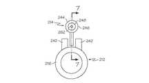
まず図面を参照すると、全体にわたって同様の参照符号は、同様の素子を表わし、図1〜図3は、本発明の実施例を示す。図1〜図3に示す実施例の第1の表現(expression)は、可撓性の医療用カテーテル12とカテーテル付属装置14とを含む医療機器10に対するものである。カテーテル12は、患者20の体腔18内に挿入可能な遠位端部16を有する。装置14は、カテーテル12にスライド可能に係合できる。カテーテル12および装置14のうち一方は、磁性材(magnetic material)22を含み、カテーテル12および装置14のうち他方は、電気的に電圧印加可能な巻線14、26および28を含む。カテーテル12および装置14は、それらカテーテル12および装置14のいずれか一方を固定しながら巻線24、26および28に制御可能に電気的に電圧印加すると、カテーテル12および装置14のうち他方がスライドするように移動する、リニアモーター30として動作するように構成されている。 Referring initially to the drawings, wherein like reference numerals represent like elements throughout, FIGS. 1-3 illustrate embodiments of the present invention. The first expression of the embodiment shown in FIGS. 1-3 is for a
用語「磁性材」は、磁化可能な材料を含み、また永久磁石を含むことに注意されたい。またリニアモーターのさまざまな設計および動作は、当該分野で周知であることにも注意されたい。巻線の巻数、ならびに巻線の数および配置は、熟練者に委ねられる。 Note that the term “magnetic material” includes magnetizable materials and also includes permanent magnets. It should also be noted that the various designs and operations of linear motors are well known in the art. The number of windings and the number and arrangement of the windings are left to the skilled person.
図1〜図3に図示の実施例の第1表現の一適用例(one application of the first expression)では、カテーテル12は、可撓性の内視鏡挿入管32である。一変形例では、可撓性の内視鏡挿入管32は、一本の作業通路34を有する。内視鏡を用いない適用(non-endoscope applications)は、当業者に委ねられる。 In one application of the first expression of the first embodiment of the embodiment illustrated in FIGS. 1-3, the
図1〜図3の実施例の第1表現の第1の実行例(first implementation of the first expression)においては、装置14は可撓性のカテーテルガイド部材(catheter-guiding member)36である。一変形例では、カテーテル12は、カテーテル内腔(catheter lumen)38を含み、カテーテルガイド部材36は、カテーテル内腔38に配置されることができる。一変更例では、カテーテル12は、巻線24、26および28を含み、巻線24、26および28は、カテーテル12の遠位端部16に近接して配置される。第1の例では、カテーテルガイド部材36は、カテーテルガイドワイヤー40である。材料の一つの選択において、ガイドワイヤー40は、鉄を含む。 In a first implementation of the first expression of the first representation of the embodiment of FIGS. 1-3, the
図4の第1代替実施例(first alternate embodiment)に示す第2の例では、カテーテルガイド部材136は、熟練者には分かるように、より大きな起磁力に備えてより大きな面積を提供するカテーテルガイドリボン140である。一変形例では、ガイドリボン140は、カテーテル112内の内腔分割壁(lumen-dividing wall)142とスライドして係合する。一変更例では、壁142は巻線を含む(図3には示されていないが、巻線を示す図3の断面図は図2と同様に見える)。材料の一つの選択において、ガイドリボン140は、鉄を含む。 In the second example shown in the first alternate embodiment of FIG. 4, the
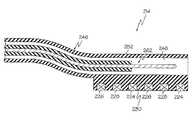
第2の実行例においては、図5〜図7の第2代替実施例に示すように、カテーテル212は外部レール242を含み、付属装置214は、リニアモーター230の動作中に外部レール242に沿ってスライドするように構成されている。一変形例では、装置214は遠位端部244を有し、装置214は、巻線224、226および228を含み、巻線224、226および228は、装置214の遠位端部244に近接して配置される。一例では、装置214は、付属作業通路248を有する可撓性の付属チューブ246を含む。材料の一つの選択において、外部レール242は、内部に埋め込まれた鉄の粒子(明確にするために図7では除いてある)を有するエラストマーを含む。第1の構造例では、装置214は、磁力で外部レール242に連結され、カテーテル212の遠位端部216の停止部(stop)(図示せず)が、付属チューブ246の進行を制限する。図示していない第2の構造例では、装置は、さねはぎ継ぎの配列(tongue and groove arrangement)によって外部レールに連結される。他の連結構造は熟練者に委ねられる。 In the second implementation, as shown in the second alternative embodiment of FIGS. 5-7, the
図1〜図3に示す実施例の第2の表現(expression)は、可撓性の医療用カテーテル12、カテーテル付属装置14、およびリニアモーターコントローラー50を含む医療機器10に対するものである。カテーテル12は、患者20の体腔18内に挿入可能な遠位端部16を有する。装置14はカテーテル12にスライド可能に係合する。カテーテル12および装置14のうち一方は磁性材22を含み、カテーテル12および装置14のうち他方が、電気的に電圧印加可能な巻線24、26および28を含む。カテーテル12および装置14は、それらカテーテル12および装置14のいずれか一方を固定しながら巻線24、26および28に制御可能に電気的に電圧印加すると、カテーテル12および装置14のうち他方がスライドするように移動する、リニアモーター30として動作するように構成されている。コントローラー50は、巻線24、26および28に動作可能に接続されている。 The second expression of the embodiment shown in FIGS. 1-3 is for a
図1〜図3に図示の実施例の第2表現の一適用例では、カテーテル12は、可撓性の内視鏡挿入管32である。 In one application of the second representation of the embodiment shown in FIGS. 1-3, the
図1〜図3の実施例の第2表現の第1の実行例においては、装置14は、可撓性のカテーテルガイド部材36である。一変形例では、カテーテル12は、カテーテル内腔38を含み、カテーテルガイド部材36は、カテーテル内腔38に配置される。一使用例において、コントローラー50は、使用者により作動されると、巻線24、26および28に制御可能に電気的に電圧印加して、これにより、カテーテルガイド部材36が使用者によって固定されているときには、カテーテル12をガイド部材36に沿ってスライドするように移動させる。 In a first implementation of the second representation of the embodiment of FIGS. 1-3, the
第2の実行例において、図5〜図7の第2代替実施例に示すように、カテーテル212は外部レール242を含み、付属装置214は、コントローラー(図1および図3においてコントローラー50として示されている)の作動中に外部レール242に沿ってスライドするように構成されている。一例において、装置214は、付属作業通路248と遠位付属チューブ部分252とを有する可撓性の付属チューブ246を含み、コントローラー(図1および図3においてコントローラー50として示されている)は、使用者により作動されると、巻線224、226および228に制御可能に電気的に電圧印加して、これにより、カテーテル212が使用者により固定されているときには、遠位付属チューブ部分252を外部レール242に沿ってスライドするように移動させる。 In the second implementation, as shown in the second alternative embodiment of FIGS. 5-7, the
図1〜図3の実施例の第1および/あるいは第2表現の一使用可能例において、医療機器10は、カテーテル12の近位端部56に取付けられたハンドピース(handpiece)54を含み、ハンドピース54は、コントローラー50を含み、コントローラー50は、使用者がそれを作動させるためのボタン58を有する。一変形例においては、図3に示すようにワイヤー60が、コントローラー50を巻線24、26および28に接続している。付属作業通路248を有する可撓性の付属チューブ246の例の一変更例では、医療用ニードルナイフ(needle knife)などのエンドエフェクタ262は、患者の医学的観察および/または治療のために、付属チューブ246から延びるように付属作業通路248内を手作業で移動することができる。他のタイプの医療用エンドエフェクタは、撮像装置(imagers)、洗浄器(irrigators)、切削刃(cutting blades)、ワイヤースネア(wire snares)、および超音波変換器(ultrasound transducers)を含むが、これらに限定されるものではない。 In one possible use of the first and / or second representation of the embodiment of FIGS. 1-3, the
本発明の方法は、医療機器10の使用するためのものである。医療機器10は、可撓性の医療用カテーテル12と、カテーテル付属装置14と、リニアモーターコントローラー50とを含む。カテーテル12は、患者20の体腔18内に挿入可能な遠位端部16を有する。装置14は、カテーテル12にスライド可能に係合する。カテーテル12および装置14のうち一方は、磁性材22を含み、カテーテル12および装置14のうち他方が、電気的に電圧印加可能な巻線14、26および28を含む。カテーテル12および装置14は、それらカテーテル12および装置14のいずれか一方を固定しながら巻線24、26および28に制御可能に電気的に電圧印加すると、カテーテル12および装置14のうち他方がスライドするように移動する、リニアモーター30として動作するように構成されている。コントローラー50は、巻線24、26および28に動作可能に接続されている。本方法は、カテーテル12の遠位端部16を体腔18内に挿入するステップを含む。この方法はまた、カテーテル12および付属装置14のうち一方を固定するステップを含む。この方法は、コントローラー50を作動させてカテーテル12および付属装置14のうち他方を体腔18内で前進させるステップをさらに含む。 The method of the present invention is for use with a
本方法の第1の使用例では、装置14は、可撓性のカテーテルガイド部材36であり、カテーテル12はカテーテル内腔38を含み、ガイド部材36はカテーテル内腔38内に配置され、ガイド部材36が固定されているときに、コントローラー50を作動させることにより、巻線24、26および28に制御可能に電気的に電圧印加して、カテーテル12をガイド部材36に沿ってスライドするように移動させる。一拡張例では、本方法はまた、ガイド部材36を固定し、かつコントローラー50を作動させる前に、カテーテル内腔38内をスライドするようにガイド部材36を手作業で前進させるステップを含む。 In a first use case of the method, the
本方法の第2の使用例では、カテーテル212は、外部レール242を含み、コントローラー(図1および図3にコントローラー50として示されている)を作動させることにより、カテーテル212が固定されたときに、装置214を外部レール242に沿ってスライドするように移動させる。一拡張例では、本方法は、カテーテル212を固定し、かつコントローラーを作動させる前に、カテーテル212を手作業で前進させるステップをさらに含む。 In a second use case of the method, the
この方法の一利用例では、体腔は、人間あるいは他の哺乳動物の結腸である。他の利用例では、体腔は上部胃腸管である。さらに他の利用例では、体腔は動脈内腔である。他の体腔は、当業者に委ねられる。 In one application of this method, the body cavity is the colon of a human or other mammal. In other applications, the body cavity is the upper gastrointestinal tract. In yet another application, the body cavity is an arterial lumen. Other body cavities are left to those skilled in the art.
本発明の実施例の一つあるいは複数の表現および方法から、幾つかの利益ならびに利点が得られる。第1の例では、カテーテル付属装置は、医療用ガイドワイヤーであり、このガイドワイヤーは、カテーテルから延びるように体腔内で手作業により前進させられた後に固定されており、巻線に制御可能に電気的に電圧印加すると、カテーテルがガイドワイヤーに沿ってスライドするように移動する。この例の一つの例示において、当業者には分かるように、カテーテルを前進させる力を、カテーテルの遠位端部の直ぐ近くに加えて、自走するカテーテルが望ましくない輪を形成しないようにする。第2の実施例において、付属装置は、可撓性の付属チューブを含み、カテーテルは、体腔内で手作業により前進させられた後に固定され、巻線に制御可能に電気的に電圧印加すると、付属チューブがカテーテルの外部レールに沿ってスライドするように移動する。この例の一つの例示において、当業者には分かるように、付属チューブを前進させる力を、付属チューブの遠位端部の直ぐ近くに加えて、自走する付属チューブが望ましくない輪を形成しないようにする。これらの例のいずれか一方あるいは両方の使用において、自走するカテーテルおよび/あるいは自走する付属チューブは、手作業で前進させることにより得られる速度よりも大きな前進速度を有し、それにより医療処置に要する時間が短縮される。 Several benefits and advantages are derived from one or more representations and methods of embodiments of the present invention. In the first example, the catheter attachment device is a medical guidewire that is secured after being manually advanced within the body cavity to extend from the catheter and is controllable to the winding. When voltage is applied electrically, the catheter moves so as to slide along the guide wire. In one illustration of this example, as will be appreciated by those skilled in the art, a force to advance the catheter is applied in the immediate vicinity of the distal end of the catheter so that the self-propelled catheter does not form an undesirable loop. . In a second embodiment, the attachment device includes a flexible attachment tube, the catheter is secured after being manually advanced within the body cavity, and when the controllable electrical voltage is applied to the windings, The accessory tube moves to slide along the outer rail of the catheter. In one illustration of this example, as will be appreciated by those skilled in the art, a force that advances the accessory tube is applied in the immediate vicinity of the distal end of the accessory tube so that the self-propelled accessory tube does not form an undesirable ring Like that. In the use of either or both of these examples, the self-propelled catheter and / or the self-propelled accessory tube have an advancing speed greater than that obtained by manual advancement, thereby providing a medical procedure. Is shortened.
本発明は、実施例の幾つかの表現および方法を述べて例示されたが、添付の特許請求の範囲の精神および範囲を、記載した細部に限定あるいは制限するのは出願人の意図するところではない。当業者は、本発明の範囲を逸脱することのない数多くの他の変形、変更、および置換を思い付くであろう。例えば、ロボット援用外科手術システムとの適合性を有するように、システム、装置、および方法を明らかに変更できることを考慮すると、本発明の医療機器は、ロボット援用外科手術における適用性を有する。前述の説明は、例として提供されるものであること、および当業者は添付の特許請求の範囲の範囲および精神を逸脱することのない他の変更を思いつくことを理解できるであろう。 While this invention has been illustrated by describing several representations and methods of examples, it is Applicants' intention to limit or limit the spirit and scope of the appended claims to the details described. Absent. Those skilled in the art will envision many other variations, modifications, and substitutions that do not depart from the scope of the invention. For example, the medical device of the present invention has applicability in robot-assisted surgery, considering that the systems, devices, and methods can be clearly modified to be compatible with robot-assisted surgery systems. It will be understood that the foregoing description is provided by way of example, and that other modifications can be devised by those skilled in the art without departing from the scope and spirit of the appended claims.
〔実施の態様〕
(1)医療機器において、
a)患者の体腔内に挿入可能な遠位端部を有する、可撓性の医療用カテーテルと、
b)前記カテーテルとスライド可能に係合することができるカテーテル付属装置であって、
前記カテーテルおよび前記装置のうち一方は、磁性材を含み、
前記カテーテルおよび前記装置のうち他方は、電気的に電圧印加可能な巻線を含み、
前記カテーテルおよび前記装置は、前記カテーテルおよび前記装置のうち一方を固定しながら前記巻線に制御可能に電気的に電圧印加することにより、前記カテーテルおよび前記装置のうち他方をスライドするように移動させる、リニアモーターとして動作するように構成された、
カテーテル付属装置と、
を備える、医療機器。
(2)実施の態様1に記載の医療機器において、
前記カテーテルは、可撓性の内視鏡挿入管である、医療機器。
(3)実施の態様1に記載の医療機器において、
前記装置は、可撓性のカテーテルガイド部材である、医療機器。
(4)実施の態様3に記載の医療機器において、
前記カテーテルは、カテーテル内腔を含み、
前記部材は、前記カテーテル内腔内に配置されることができる、医療機器。
(5)実施の態様4に記載の医療機器において、
前記カテーテルは、巻線を含み、
前記巻線は、前記カテーテルの前記遠位端部に近接して配置されている、医療機器。
(6)実施の態様5に記載の医療機器において、
前記部材は、カテーテルガイドワイヤー、およびカテーテルガイドリボンからなる群から選ばれる、医療機器。
(7)実施の態様1に記載の医療機器において、
前記カテーテルは、外部レールを含み、
前記装置は、前記リニアモーターの動作中に前記外部レールに沿ってスライドするように構成されている、医療機器。
(8)実施の態様7に記載の医療機器において、
前記装置は、遠位端部を有し、
前記装置は、巻線を含み、
前記巻線は、前記装置の前記遠位端部に近接して配置されている、医療機器。
(9)実施の態様8に記載の医療機器において、
前記装置は付属作業通路を有する可撓性の付属チューブを含む、医療機器。Embodiment
(1) In medical equipment,
a) a flexible medical catheter having a distal end insertable into the body cavity of a patient;
b) a catheter attachment device slidably engageable with the catheter,
One of the catheter and the device includes a magnetic material,
The other of the catheter and the device includes an electrically voltageable winding,
The catheter and the device are moved to slide the other of the catheter and the device by applying a controllable electrical voltage to the winding while fixing one of the catheter and the device. Configured to operate as a linear motor,
A catheter attachment device;
A medical device comprising:
(2) In the medical device according to Embodiment 1,
The catheter is a medical device, which is a flexible endoscope insertion tube.
(3) In the medical device according to Embodiment 1,
The device is a medical device that is a flexible catheter guide member.
(4) In the medical device according to Embodiment 3,
The catheter includes a catheter lumen;
The medical device, wherein the member can be disposed within the catheter lumen.
(5) In the medical device according to Embodiment 4,
The catheter includes a winding;
The medical device, wherein the winding is disposed proximate to the distal end of the catheter.
(6) In the medical device according to Embodiment 5,
The member is a medical device selected from the group consisting of a catheter guide wire and a catheter guide ribbon.
(7) In the medical device according to Embodiment 1,
The catheter includes an outer rail;
The device is configured to slide along the outer rail during operation of the linear motor.
(8) In the medical device according to
The device has a distal end;
The apparatus includes a winding;
The medical device, wherein the winding is disposed proximate to the distal end of the device.
(9) In the medical device according to Embodiment 8,
The apparatus includes a flexible accessory tube having an accessory working channel.
(10)医療機器において、
a)患者の体腔内に挿入可能な遠位端部を有する、可撓性の医療用カテーテルと、
b)前記カテーテルとスライド可能に係合するカテーテル付属装置であって、
前記カテーテルおよび前記装置のうち一方は、磁性材を含み、
前記カテーテルおよび前記装置のうち他方は、電気的に電圧印加可能な巻線を含み、
前記カテーテルおよび前記装置は、前記カテーテルおよび前記装置のうち一方を固定しながら前記巻線に制御可能に電気的に電圧印加することにより、前記カテーテルおよび前記装置のうち他方をスライドするように移動させる、リニアモーターとして動作するように構成された、
カテーテル付属装置と、
c)前記巻線に動作可能に接続される、リニアモーターコントローラーと、
を備える、医療機器。
(11)実施の態様9に記載の医療機器において、
前記カテーテルは、可撓性の内視鏡挿入管である、医療機器。
(12)実施の態様9に記載の医療機器において、
前記装置は、可撓性のカテーテルガイド部材である、医療機器。
(13)実施の態様12に記載の医療機器において、
前記カテーテルは、カテーテル内腔を含み、
前記部材は、前記カテーテル内腔内に配置され、
前記コントローラーは、使用者により作動されると、前記巻線に制御可能に電気的に電圧印加して、これにより、前記部材が前記使用者により固定されているときには、前記部材に沿って前記カテーテルをスライドするように移動させる、医療機器。
(14)実施の態様9に記載の医療機器において、
前記カテーテルは、外部レールを含み、
前記装置は、前記コントローラーの作動中に前記外部レールに沿ってスライドするように構成された、医療機器。
(15)実施の態様14に記載の医療機器において、
前記装置は、付属作業通路、および遠位付属チューブ部分を有する、可撓性の付属チューブを含み、
前記コントローラーは、使用者により作動されると、前記巻線に制御可能に電気的に電圧印加して、これにより、前記カテーテルが前記使用者により固定されているときには、前記外部レールに沿って前記遠位付属チューブ部分をスライドするように移動させる、医療機器。(10) In medical equipment,
a) a flexible medical catheter having a distal end insertable into the body cavity of a patient;
b) a catheter attachment device slidably engaged with the catheter,
One of the catheter and the device includes a magnetic material,
The other of the catheter and the device includes an electrically voltageable winding,
The catheter and the device are moved to slide the other of the catheter and the device by applying a controllable electrical voltage to the winding while fixing one of the catheter and the device. Configured to operate as a linear motor,
A catheter attachment device;
c) a linear motor controller operably connected to the winding;
A medical device comprising:
(11) In the medical device according to Embodiment 9,
The catheter is a medical device, which is a flexible endoscope insertion tube.
(12) In the medical device according to Embodiment 9,
The device is a medical device that is a flexible catheter guide member.
(13) In the medical device according to
The catheter includes a catheter lumen;
The member is disposed within the catheter lumen;
The controller, when actuated by a user, applies a controllable electrical voltage to the winding so that when the member is fixed by the user, the catheter is moved along the member. Move the medical device to slide.
(14) In the medical device according to Embodiment 9,
The catheter includes an outer rail;
The medical device configured to slide along the outer rail during operation of the controller.
(15) In the medical device according to the fourteenth embodiment,
The apparatus includes a flexible attachment tube having an attachment working channel and a distal attachment tube portion;
The controller, when actuated by a user, applies a controllable electrical voltage to the winding so that the catheter is fixed along the outer rail when the catheter is secured by the user. A medical device that moves the distal attached tube part to slide.
(16)医療機器を使用する方法において、
前記医療機器は、
患者の体腔内に挿入可能な遠位端部を有する、可撓性の医療用カテーテル、
前記カテーテルとスライド可能に係合するカテーテル付属装置であって、
前記カテーテルおよび前記装置のうち一方は、磁性材を含み、
前記カテーテルおよび前記装置のうち他方は、電気的に電圧印加可能な巻線を含み、
前記カテーテルおよび前記装置は、前記カテーテルおよび前記装置のうち一方を固定しながら前記巻線に制御可能に電気的に電圧印加することにより、前記カテーテルおよび前記装置のうち他方をスライドするように移動させる、リニアモーターとして動作するように構成された、
カテーテル付属装置、ならびに、
前記巻線に動作可能に接続された、リニアモーターコントローラー、
を備え、
前記方法は、
a)前記カテーテルの前記遠位端部を前記体腔内に挿入するステップと、
b)前記カテーテルおよび前記装置のうち一方を固定するステップと、
c)前記コントローラーを作動させて前記カテーテルおよび前記装置のうち他方を前記体腔内で前進させるステップと、
を含む、方法。
(17)実施の態様16に記載の方法において、
前記装置は、可撓性のカテーテルガイド部材であり、
前記カテーテルは、カテーテル内腔を含み、
前記部材は、前記カテーテル内腔内に配置され、
前記部材が固定されているときに、前記コントローラーを作動させることにより、前記巻線に制御可能に電気的に電圧印加して、前記部材に沿って前記カテーテルをスライドするように移動させる、方法。
(18)実施の態様17に記載の方法において、
前記部材を固定し、かつ前記コントローラーを作動させる前に、前記カテーテル内腔内をスライドするように前記部材を手作業で前進させるステップ、
をさらに含む、方法。
(19)実施の態様16に記載の方法において、
前記カテーテルは、外部レールを含み、
前記カテーテルが固定されているときに、前記コントローラーを作動させることにより、前記外部レールに沿って前記装置をスライドするように移動させる、方法。
(20)実施の態様19に記載の方法において、
前記カテーテルを固定して前記コントローラーを作動させる前に、前記カテーテルを手動で前進させるステップ、
をさらに含む、方法。(16) In a method of using a medical device,
The medical device is
A flexible medical catheter having a distal end insertable into a body cavity of a patient;
A catheter attachment device slidably engaged with the catheter,
One of the catheter and the device includes a magnetic material,
The other of the catheter and the device includes an electrically voltageable winding,
The catheter and the device are moved to slide the other of the catheter and the device by applying a controllable electrical voltage to the winding while fixing one of the catheter and the device. Configured to operate as a linear motor,
Catheter attachment devices, and
A linear motor controller operably connected to the winding;
With
The method
a) inserting the distal end of the catheter into the body cavity;
b) fixing one of the catheter and the device;
c) actuating the controller to advance the other of the catheter and the device into the body cavity;
Including a method.
(17) In the method according to the sixteenth embodiment,
The device is a flexible catheter guide member;
The catheter includes a catheter lumen;
The member is disposed within the catheter lumen;
A method wherein the controller is actuated to apply a controllable electrical voltage to the winding to slide the catheter along the member when the member is fixed.
(18) In the method according to Embodiment 17,
Manually advancing the member to slide within the catheter lumen before securing the member and actuating the controller;
Further comprising a method.
(19) In the method according to the sixteenth embodiment,
The catheter includes an outer rail;
A method of moving the device to slide along the outer rail by actuating the controller when the catheter is fixed.
(20) In the method according to Embodiment 19,
Manually advancing the catheter before securing the catheter and activating the controller;
Further comprising a method.
Claims (3)
Translated fromJapanesea)患者の体腔内に挿入可能な遠位端部を有する、可撓性の医療用カテーテルと、
b)前記医療用カテーテルとスライド可能に係合することができるカテーテル付属装置と、
を含み
前記医療用カテーテルおよび前記カテーテル付属装置のうち一方は、磁性材を含み、
前記医療用カテーテルおよび前記カテーテル付属装置のうち他方は、電気的に電圧印加可能な巻線を含み、
前記医療用カテーテルおよび前記カテーテル付属装置は、前記医療用カテーテルおよび前記カテーテル付属装置のうち一方を固定しながら前記巻線に制御可能に電気的に電圧印加することにより、前記医療用カテーテルおよび前記カテーテル付属装置のうち他方をスライドするように移動させる、リニアモーターとして動作するように構成されており、
前記医療用カテーテルは、可撓性の内視鏡挿入管であり、
前記カテーテル付属装置は、可撓性のカテーテルガイド部材であり、
前記医療用カテーテルは、カテーテル内腔を含み、
前記カテーテルガイド部材は、前記カテーテル内腔内に配置されることができ、
前記医療用カテーテルは、巻線を含み、
前記巻線は、前記医療用カテーテルの前記遠位端部に近接して配置されている、医療機器。In medical equipment,
a) a flexible medical catheter having a distal end insertable into the body cavity of a patient;
a catheter accessory device capable of b) engagable saidmedical catheter and the slide,
One of themedical catheter and thecatheter attachment device includes a magnetic material,
The other of themedical catheter and thecatheter accessory device includes a winding capable of applying an electrical voltage,
Themedical catheter and thecatheter accessory device, by controllably electrically voltage applied to the windings while fixing one of themedical catheter and thecatheter accessory device, wherein themedical catheter and saidcatheterIt is configured to operate as a linear motor that moves the other of theattached devices to slide,
The medical catheter is a flexible endoscope insertion tube,
The catheter attachment device is a flexible catheter guide member,
The medical catheter includes a catheter lumen;
The catheter guide member can be disposed within the catheter lumen;
The medical catheter includes a winding;
The medical device, wherein the winding is disposed proximate to the distal end of the medical catheter .
前記カテーテルガイド部材は、カテーテルガイドワイヤー、およびカテーテルガイドリボンからなる群から選ばれる、医療機器。The medical device according to claim1 , wherein
Thecatheter guide member is a medical device selected from the group consisting of a catheter guide wire and a catheter guide ribbon.
c)前記巻線に動作可能に接続される、リニアモーターコントローラーと、
をさらに備える、医療機器。The medical device accordingto claim 1 , wherein
c) a linear motor controller operably connected to the winding;
Further comprising a medical device.
Applications Claiming Priority (2)
| Application Number | Priority Date | Filing Date | Title |
|---|---|---|---|
| US11/435,551US20070270639A1 (en) | 2006-05-17 | 2006-05-17 | Medical instrument having a catheter and having a catheter accessory device and method for using |
| US11/435,551 | 2006-05-17 |
Publications (2)
| Publication Number | Publication Date |
|---|---|
| JP2007307375A JP2007307375A (en) | 2007-11-29 |
| JP5095265B2true JP5095265B2 (en) | 2012-12-12 |
Family
ID=38179695
Family Applications (1)
| Application Number | Title | Priority Date | Filing Date |
|---|---|---|---|
| JP2007130810AExpired - Fee RelatedJP5095265B2 (en) | 2006-05-17 | 2007-05-16 | Medical device having catheter and catheter attachment device |
Country Status (7)
| Country | Link |
|---|---|
| US (1) | US20070270639A1 (en) |
| EP (1) | EP1857041B1 (en) |
| JP (1) | JP5095265B2 (en) |
| CN (1) | CN101073488B (en) |
| AU (1) | AU2007202140B2 (en) |
| CA (1) | CA2589400C (en) |
| DE (1) | DE602007002520D1 (en) |
Families Citing this family (33)
| Publication number | Priority date | Publication date | Assignee | Title |
|---|---|---|---|---|
| US10064540B2 (en) | 2005-02-02 | 2018-09-04 | Intuitive Surgical Operations, Inc. | Visualization apparatus for transseptal access |
| US7860555B2 (en) | 2005-02-02 | 2010-12-28 | Voyage Medical, Inc. | Tissue visualization and manipulation system |
| US8137333B2 (en) | 2005-10-25 | 2012-03-20 | Voyage Medical, Inc. | Delivery of biological compounds to ischemic and/or infarcted tissue |
| US9510732B2 (en) | 2005-10-25 | 2016-12-06 | Intuitive Surgical Operations, Inc. | Methods and apparatus for efficient purging |
| US20080015569A1 (en) | 2005-02-02 | 2008-01-17 | Voyage Medical, Inc. | Methods and apparatus for treatment of atrial fibrillation |
| US11478152B2 (en) | 2005-02-02 | 2022-10-25 | Intuitive Surgical Operations, Inc. | Electrophysiology mapping and visualization system |
| US9055906B2 (en) | 2006-06-14 | 2015-06-16 | Intuitive Surgical Operations, Inc. | In-vivo visualization systems |
| WO2008028149A2 (en) | 2006-09-01 | 2008-03-06 | Voyage Medical, Inc. | Electrophysiology mapping and visualization system |
| US10004388B2 (en) | 2006-09-01 | 2018-06-26 | Intuitive Surgical Operations, Inc. | Coronary sinus cannulation |
| US20080097476A1 (en) | 2006-09-01 | 2008-04-24 | Voyage Medical, Inc. | Precision control systems for tissue visualization and manipulation assemblies |
| US9226648B2 (en) | 2006-12-21 | 2016-01-05 | Intuitive Surgical Operations, Inc. | Off-axis visualization systems |
| US8657805B2 (en) | 2007-05-08 | 2014-02-25 | Intuitive Surgical Operations, Inc. | Complex shape steerable tissue visualization and manipulation catheter |
| FR2931599A1 (en)* | 2008-05-26 | 2009-11-27 | Univ Pasteur | DEVICE FOR DISPLACING CONTROL IN TRANSLATION OF AN ELONGATED MEMBER |
| JP5723081B2 (en)* | 2008-06-19 | 2015-05-27 | 石川 義弘 | Medical tube or drug guidance system |
| US9717403B2 (en) | 2008-12-05 | 2017-08-01 | Jeffrey B. Kleiner | Method and apparatus for performing retro peritoneal dissection |
| US8864654B2 (en) | 2010-04-20 | 2014-10-21 | Jeffrey B. Kleiner | Method and apparatus for performing retro peritoneal dissection |
| WO2010085073A2 (en)* | 2009-01-20 | 2010-07-29 | 주식회사 래보 | Surgical robot for liposuction |
| JP5580540B2 (en)* | 2009-03-02 | 2014-08-27 | オリンパス株式会社 | Guide device |
| WO2011148894A1 (en)* | 2010-05-28 | 2011-12-01 | オリンパスメディカルシステムズ株式会社 | Endoscope |
| WO2012007053A1 (en)* | 2010-07-16 | 2012-01-19 | Ethicon Endo-Surgery, Inc. | A length adjustable catheter for directing biliopancreatic secretions |
| CN102553009A (en)* | 2012-03-07 | 2012-07-11 | 中国人民解放军第二军医大学 | Peritoneal dialysis catheter positioning and adjusting device |
| CN103110441B (en)* | 2013-01-29 | 2016-06-15 | 北京派尔特医疗科技股份有限公司 | The universal handle of electric surgery binding instrument |
| US10737061B2 (en)* | 2014-08-22 | 2020-08-11 | Jaywant P. Parmar | Advanced electromagnetic motion and tracking peripherally inserted central venous catheter system with extended endovascular applications |
| JP6371176B2 (en)* | 2014-09-17 | 2018-08-08 | テルモ株式会社 | catheter |
| US10517679B2 (en)* | 2015-12-15 | 2019-12-31 | Brainlab Ag | Electromagnetic guiding tube for elongated medical implants |
| US20200281619A1 (en)* | 2017-10-03 | 2020-09-10 | Interscope, Inc. | Insertable endoscopic instrument for tissue removal with retractable tool at cutting tip |
| CN108815680B (en)* | 2018-04-17 | 2022-03-29 | 杨延辉 | Device for guiding placement position of stomach tube/jejunum nutrient canal under direct vision of laparoscope |
| WO2020142340A1 (en)* | 2018-12-31 | 2020-07-09 | Xact Medical, Inc. | Subcutaneous delivery system |
| US20230052862A1 (en) | 2021-08-12 | 2023-02-16 | Imperative Care, Inc. | Sterile packaging assembly for robotic interventional device |
| US12419703B2 (en) | 2022-08-01 | 2025-09-23 | Imperative Care, Inc. | Robotic drive system for achieving supra-aortic access |
| US20240041480A1 (en) | 2022-08-02 | 2024-02-08 | Imperative Care, Inc. | Multi catheter system with integrated fluidics management |
| US20240181213A1 (en) | 2022-12-01 | 2024-06-06 | Imperative Care, Inc. | Drive table with shuttle |
| US12377206B2 (en) | 2023-05-17 | 2025-08-05 | Imperative Care, Inc. | Fluidics control system for multi catheter stack |
Family Cites Families (111)
| Publication number | Priority date | Publication date | Assignee | Title |
|---|---|---|---|---|
| US1225771A (en)* | 1916-09-01 | 1917-05-15 | James P Clare | Ecraseur or such like instrument. |
| US2976865A (en)* | 1958-10-21 | 1961-03-28 | Shipley Richard Edwin | Cylindrical strain gauge |
| US3521620A (en)* | 1967-10-30 | 1970-07-28 | William A Cook | Vascular coil spring guide with bendable tip |
| DE2160466A1 (en)* | 1970-12-05 | 1972-06-22 | Olympus Optical Co. Ltd., Tokio | Excision forceps |
| US3799151A (en)* | 1970-12-21 | 1974-03-26 | Olympus Optical Co | Controllably bendable tube of an endoscope |
| DE2132808C3 (en)* | 1971-07-01 | 1981-10-29 | Deyhle, Peter, Dr.med., 8520 Erlangen | Device for the diathermic removal of growths |
| US4102478A (en)* | 1976-12-27 | 1978-07-25 | Constantin Samoilov | Needle threader |
| US4326530A (en)* | 1980-03-05 | 1982-04-27 | Fleury Jr George J | Surgical snare |
| US4493320A (en)* | 1982-04-02 | 1985-01-15 | Treat Michael R | Bipolar electrocautery surgical snare |
| JPS6176147A (en)* | 1984-09-21 | 1986-04-18 | オリンパス光学工業株式会社 | High frequency incision appliance |
| KR900005760B1 (en)* | 1986-02-19 | 1990-08-09 | 가부시기가이샤 히다찌 세이사꾸쇼 | Movable Coil Linear Motor |
| US4739768B2 (en)* | 1986-06-02 | 1995-10-24 | Target Therapeutics Inc | Catheter for guide-wire tracking |
| US4735194C1 (en)* | 1987-01-13 | 2001-05-08 | Dept Of Veterans Affairs The U | Flexile endoscopic ligating instrument |
| US4893613A (en)* | 1987-11-25 | 1990-01-16 | Hake Lawrence W | Endoscope construction with means for controlling rigidity and curvature of flexible endoscope tube |
| US4890602A (en)* | 1987-11-25 | 1990-01-02 | Hake Lawrence W | Endoscope construction with means for controlling rigidity and curvature of flexible endoscope tube |
| US4930494A (en)* | 1988-03-09 | 1990-06-05 | Olympus Optical Co., Ltd. | Apparatus for bending an insertion section of an endoscope using a shape memory alloy |
| US5002041A (en)* | 1989-05-12 | 1991-03-26 | Kabushiki Kaisha Machida Seisakusho | Bending device and flexible tube structure |
| JP2948834B2 (en)* | 1989-09-05 | 1999-09-13 | オリンパス光学工業株式会社 | Endoscope insertion device |
| US5035696A (en)* | 1990-02-02 | 1991-07-30 | Everest Medical Corporation | Electrosurgical instrument for conducting endoscopic retrograde sphincterotomy |
| US5254088A (en)* | 1990-02-02 | 1993-10-19 | Ep Technologies, Inc. | Catheter steering mechanism |
| US5152744A (en)* | 1990-02-07 | 1992-10-06 | Smith & Nephew Dyonics | Surgical instrument |
| US5078716A (en)* | 1990-05-11 | 1992-01-07 | Doll Larry F | Electrosurgical apparatus for resecting abnormal protruding growth |
| US5201741A (en)* | 1990-07-24 | 1993-04-13 | Andrew Surgical, Inc. | Surgical snare with shape memory effect wire |
| US5531664A (en)* | 1990-12-26 | 1996-07-02 | Olympus Optical Co., Ltd. | Bending actuator having a coil sheath with a fixed distal end and a free proximal end |
| US5409453A (en)* | 1992-08-12 | 1995-04-25 | Vidamed, Inc. | Steerable medical probe with stylets |
| US5433721A (en)* | 1992-01-17 | 1995-07-18 | Ethicon, Inc. | Endoscopic instrument having a torsionally stiff drive shaft for applying fasteners to tissue |
| US5201732A (en)* | 1992-04-09 | 1993-04-13 | Everest Medical Corporation | Bipolar sphincterotomy utilizing side-by-side parallel wires |
| WO1993020878A1 (en)* | 1992-04-10 | 1993-10-28 | Cardiorhythm | Shapable handle for steerable electrode catheter |
| US5522829A (en)* | 1992-04-16 | 1996-06-04 | Arthur D. Little Enterprises, Inc. | Surgical cutting instrument |
| US5482029A (en)* | 1992-06-26 | 1996-01-09 | Kabushiki Kaisha Toshiba | Variable flexibility endoscope system |
| US5342299A (en)* | 1992-07-06 | 1994-08-30 | Catheter Imaging Systems | Steerable catheter |
| US5776080A (en)* | 1992-08-12 | 1998-07-07 | Scimed Life Systems, Inc. | Shaft movement control apparatus |
| US5293869A (en)* | 1992-09-25 | 1994-03-15 | Ep Technologies, Inc. | Cardiac probe with dynamic support for maintaining constant surface contact during heart systole and diastole |
| JPH06114037A (en)* | 1992-10-05 | 1994-04-26 | Olympus Optical Co Ltd | Capsule device for medical treatment |
| US5346504A (en)* | 1992-11-19 | 1994-09-13 | Ethicon, Inc. | Intraluminal manipulator with a head having articulating links |
| US5628719A (en)* | 1992-11-25 | 1997-05-13 | Scimed Life Systems, Inc. | In vivo mechanical energy source and perfusion pump |
| US5353807A (en)* | 1992-12-07 | 1994-10-11 | Demarco Thomas J | Magnetically guidable intubation device |
| US5431671A (en)* | 1993-05-28 | 1995-07-11 | Nallakrishnan; Ravi | Surgical knife with retractable and angularly adjustable blade |
| DE4323585A1 (en)* | 1993-07-14 | 1995-01-19 | Delma Elektro Med App | Bipolar high-frequency surgical instrument |
| US5792165A (en)* | 1993-07-21 | 1998-08-11 | Charles H. Klieman | Endoscopic instrument with detachable end effector |
| US5454827A (en)* | 1994-05-24 | 1995-10-03 | Aust; Gilbert M. | Surgical instrument |
| US5542948A (en)* | 1994-05-24 | 1996-08-06 | Arrow Precision Products, Inc. | Surgical combination inject and snare apparatus |
| US5706827A (en)* | 1994-09-21 | 1998-01-13 | Scimed Life Systems, Inc. | Magnetic lumen catheter |
| US5728044A (en)* | 1995-03-10 | 1998-03-17 | Shan; Yansong | Sensor device for spacial imaging of endoscopes |
| JPH08322786A (en)* | 1995-05-30 | 1996-12-10 | Toshiba Medical Eng Co Ltd | In-vivo diagnostic treatment device |
| US5810715A (en)* | 1995-09-29 | 1998-09-22 | Olympus Optical Co., Ltd. | Endoscope provided with function of being locked to flexibility of insertion part which is set by flexibility modifying operation member |
| US5749828A (en)* | 1995-12-22 | 1998-05-12 | Hewlett-Packard Company | Bending neck for use with invasive medical devices |
| JP4110294B2 (en)* | 1996-01-11 | 2008-07-02 | ボストン・サイエンティフィック・マイアミ・コーポレーション | Flexible endoscopic instrument with a sheath having tactile and visible position indicating means |
| US6036687A (en)* | 1996-03-05 | 2000-03-14 | Vnus Medical Technologies, Inc. | Method and apparatus for treating venous insufficiency |
| US5752961A (en)* | 1996-03-25 | 1998-05-19 | The University Of Kentucky Research Foundation | Angled snare assembly |
| US5810807A (en)* | 1996-05-22 | 1998-09-22 | Ganz; Robert A. | Sphincterotome with deflectable cutting plane and method of using the same |
| US6371907B1 (en)* | 1996-11-18 | 2002-04-16 | Olympus Optical Co., Ltd. | Endoscope apparatus driving manipulation wires with drive motor in drum portion |
| US5897554A (en)* | 1997-03-01 | 1999-04-27 | Irvine Biomedical, Inc. | Steerable catheter having a loop electrode |
| US5910148A (en)* | 1997-08-06 | 1999-06-08 | Mitek Surgical Products, Inc. | Suture retrograder |
| US6917834B2 (en)* | 1997-12-03 | 2005-07-12 | Boston Scientific Scimed, Inc. | Devices and methods for creating lesions in endocardial and surrounding tissue to isolate focal arrhythmia substrates |
| US6093185A (en)* | 1998-03-05 | 2000-07-25 | Scimed Life Systems, Inc. | Expandable PMR device and method |
| US6066102A (en)* | 1998-03-09 | 2000-05-23 | Spectrascience, Inc. | Optical biopsy forceps system and method of diagnosing tissue |
| US6066145A (en)* | 1998-03-26 | 2000-05-23 | Wurster; Helmut | Multi-ligator device that generates a signal when a ligation ring is released |
| JP3919947B2 (en)* | 1998-07-09 | 2007-05-30 | アルフレッサファーマ株式会社 | Microwave surgical electrode device |
| US6352503B1 (en)* | 1998-07-17 | 2002-03-05 | Olympus Optical Co., Ltd. | Endoscopic surgery apparatus |
| JP2000051149A (en)* | 1998-08-05 | 2000-02-22 | Techno Sophia:Kk | Linear motor driven-non-blind spot diagnosis and treatment endoscope for colon |
| JP2000051218A (en)* | 1998-08-07 | 2000-02-22 | Terumo Corp | Direct acting position moving device for ultrasonic catheter |
| JP3244660B2 (en)* | 1998-08-17 | 2002-01-07 | 旭光学工業株式会社 | Endoscope treatment tool |
| US6074408A (en)* | 1998-10-13 | 2000-06-13 | Freeman; Kenneth V. | Modular medical instrument and method of using same |
| JP3634644B2 (en)* | 1998-10-29 | 2005-03-30 | ペンタックス株式会社 | Endoscope operation part |
| US6174280B1 (en)* | 1998-11-19 | 2001-01-16 | Vision Sciences, Inc. | Sheath for protecting and altering the bending characteristics of a flexible endoscope |
| US6203494B1 (en)* | 1999-03-02 | 2001-03-20 | Olympus Optical Co., Ltd. | Endoscope capable of varying hardness of flexible part of insertion unit thereof |
| US20040044350A1 (en)* | 1999-04-09 | 2004-03-04 | Evalve, Inc. | Steerable access sheath and methods of use |
| GB2352636B (en)* | 1999-08-03 | 2003-05-14 | Univ College London Hospitals | Improved passage-travelling device |
| DE50014373D1 (en)* | 1999-09-09 | 2007-07-12 | Tuebingen Scient Medical Gmbh | SURGICAL INSTRUMENT FOR MINIMALLY INVASIVE INTERVENTIONS |
| JP3651329B2 (en)* | 1999-09-30 | 2005-05-25 | フジノン株式会社 | Angle section of endoscope |
| US6450948B1 (en)* | 1999-11-02 | 2002-09-17 | Vista Medical Technologies, Inc. | Deflecting tip for surgical cannula |
| US6423059B1 (en)* | 1999-11-16 | 2002-07-23 | Sulzer Medica Usa Inc. | Radio frequency ablation apparatus with remotely articulating and self-locking electrode wand |
| US6699179B2 (en)* | 2000-01-27 | 2004-03-02 | Scimed Life Systems, Inc. | Catheter introducer system for exploration of body cavities |
| US6858005B2 (en)* | 2000-04-03 | 2005-02-22 | Neo Guide Systems, Inc. | Tendon-driven endoscope and methods of insertion |
| US6800056B2 (en)* | 2000-04-03 | 2004-10-05 | Neoguide Systems, Inc. | Endoscope with guiding apparatus |
| US6395001B1 (en)* | 2000-04-10 | 2002-05-28 | Health Care Technologies, Llc | Electrosurgical electrode for wedge resection |
| US6443944B1 (en)* | 2000-05-19 | 2002-09-03 | Rajiv Doshi | Surgical devices comprising articulated members and methods for using the same |
| DE10026847A1 (en)* | 2000-05-31 | 2002-01-10 | Engelbert Gmeilbauer | Tool for tensioning or releasing / opening spring clamping elements |
| US6689119B1 (en)* | 2000-06-02 | 2004-02-10 | Scimed Life Systems, Inc. | Self-aligning medical device |
| GB0014028D0 (en)* | 2000-06-09 | 2000-08-02 | Oxford Instr Ltd | Catheter guide assembly |
| JP2002000556A (en)* | 2000-06-26 | 2002-01-08 | Nonomura Tomosuke | Endoscope |
| US6717092B2 (en)* | 2000-08-11 | 2004-04-06 | Pentax Corporation | Method of manufacturing treatment instrument of endoscope |
| US6569105B1 (en)* | 2000-09-14 | 2003-05-27 | Syntheon, Llc | Rotatable and deflectable biopsy forceps |
| GB0029158D0 (en)* | 2000-11-29 | 2001-01-17 | Oxford Instr Plc | Catheter steering apparatus and method |
| US6716226B2 (en)* | 2001-06-25 | 2004-04-06 | Inscope Development, Llc | Surgical clip |
| US6579300B2 (en)* | 2001-01-18 | 2003-06-17 | Scimed Life Systems, Inc. | Steerable sphincterotome and methods for cannulation, papillotomy and sphincterotomy |
| US6837884B2 (en)* | 2001-06-18 | 2005-01-04 | Arthrocare Corporation | Electrosurgical apparatus having compound return electrode |
| US6764441B2 (en)* | 2001-09-17 | 2004-07-20 | Case Western Reserve University | Peristaltically self-propelled endoscopic device |
| JP5073895B2 (en)* | 2001-09-25 | 2012-11-14 | オリンパス株式会社 | Endoscopic treatment tool |
| US6616661B2 (en)* | 2001-09-28 | 2003-09-09 | Ethicon, Inc. | Surgical device for clamping, ligating, and severing tissue |
| US6835173B2 (en)* | 2001-10-05 | 2004-12-28 | Scimed Life Systems, Inc. | Robotic endoscope |
| US6602267B2 (en)* | 2001-10-17 | 2003-08-05 | Medcanica, Inc. | Articulable and reciprocable surgical knife |
| US20030153866A1 (en)* | 2001-11-09 | 2003-08-14 | Long Gary L. | Self-propelled, intraluminal device with hollow, cylindrical head and method of use |
| US6866626B2 (en)* | 2001-11-09 | 2005-03-15 | Ethicon-Endo Surgery, Inc. | Self-propelled, intraluminal device with working channel and method of use |
| US6730097B2 (en)* | 2001-12-07 | 2004-05-04 | William G. Dennis | Surgical snare with steering tether and method of using same |
| EP1455635B1 (en)* | 2001-12-20 | 2011-08-10 | Endogene Pty. Ltd. | Self-advancing device |
| JP3826045B2 (en)* | 2002-02-07 | 2006-09-27 | オリンパス株式会社 | Endoscope hood |
| JP2003250748A (en)* | 2002-03-01 | 2003-09-09 | Fuji Photo Optical Co Ltd | Cover for endoscope |
| US6679836B2 (en)* | 2002-06-21 | 2004-01-20 | Scimed Life Systems, Inc. | Universal programmable guide catheter |
| US6863668B2 (en)* | 2002-08-16 | 2005-03-08 | Edwards Lifesciences Corporation | Articulation mechanism for medical devices |
| JP2004073582A (en)* | 2002-08-20 | 2004-03-11 | Olympus Corp | Vital tissue abscise tool |
| US7066879B2 (en)* | 2003-07-15 | 2006-06-27 | The Trustees Of Columbia University In The City Of New York | Insertable device and system for minimal access procedure |
| US7918786B2 (en)* | 2003-11-11 | 2011-04-05 | Olympus Corporation | Capsule type medical device system, and capsule type medical device |
| US7799050B2 (en)* | 2004-05-05 | 2010-09-21 | Boston Scientific Scimed, Inc. | Devices and methods for magnetically manipulating intravascular devices |
| WO2005113051A2 (en)* | 2004-05-14 | 2005-12-01 | Ethicon Endo-Surgery, Inc. | Medical instrument having a medical guidewire |
| US7311674B2 (en)* | 2004-06-28 | 2007-12-25 | Scimed Life Systems, Inc. | End effector assembly cap and tissue removal device and related methods |
| US7298278B2 (en)* | 2004-08-10 | 2007-11-20 | Robertshaw Controls Company | Automatic delivery/drain detection using a level monitoring system |
| CN1332629C (en)* | 2004-09-02 | 2007-08-22 | 上海交通大学 | Active intestinal endoscope robot system |
| US7347868B2 (en)* | 2004-10-26 | 2008-03-25 | Baronova, Inc. | Medical device delivery catheter |
| US20070149853A1 (en)* | 2005-12-24 | 2007-06-28 | Chang Chun Y | Industrial endoscope |
- 2006
- 2006-05-17USUS11/435,551patent/US20070270639A1/ennot_activeAbandoned
- 2007
- 2007-05-14AUAU2007202140Apatent/AU2007202140B2/ennot_activeCeased
- 2007-05-16EPEP07252011Apatent/EP1857041B1/ennot_activeCeased
- 2007-05-16CACA2589400Apatent/CA2589400C/ennot_activeExpired - Fee Related
- 2007-05-16JPJP2007130810Apatent/JP5095265B2/ennot_activeExpired - Fee Related
- 2007-05-16DEDE602007002520Tpatent/DE602007002520D1/enactiveActive
- 2007-05-17CNCN2007101049975Apatent/CN101073488B/ennot_activeExpired - Fee Related
Also Published As
| Publication number | Publication date |
|---|---|
| AU2007202140B2 (en) | 2013-03-28 |
| DE602007002520D1 (en) | 2009-11-05 |
| EP1857041A1 (en) | 2007-11-21 |
| CA2589400C (en) | 2014-07-29 |
| JP2007307375A (en) | 2007-11-29 |
| CA2589400A1 (en) | 2007-11-17 |
| EP1857041B1 (en) | 2009-09-23 |
| CN101073488A (en) | 2007-11-21 |
| AU2007202140A1 (en) | 2007-12-06 |
| CN101073488B (en) | 2010-11-17 |
| US20070270639A1 (en) | 2007-11-22 |
Similar Documents
| Publication | Publication Date | Title |
|---|---|---|
| JP5095265B2 (en) | Medical device having catheter and catheter attachment device | |
| US9095686B2 (en) | Device for the controlled translational displacement of an elongate element | |
| EP2757931B1 (en) | Access devices and related methods of use | |
| US6719763B2 (en) | Endoscopic suturing device | |
| JP3521910B1 (en) | External forceps channel device for endoscope | |
| JP5349763B2 (en) | Medical cannula and medical cannula system | |
| CN101296649A (en) | System and method for controlling force applied to a medical instrument and manipulation thereof | |
| US9427138B2 (en) | Access devices and related methods of use | |
| US11185215B2 (en) | Medical systems, devices, and related methods | |
| CN106794048A (en) | Operation input device and medical robot system | |
| EP3216380A1 (en) | Assist tool and endoscope system | |
| KR20190135333A (en) | Capsule endoscope with biopsy tool using biopsy punch | |
| JP4624714B2 (en) | Endoscope | |
| Traeger et al. | Design of a spine-inspired kinematic for the guidance of flexible instruments in minimally invasive surgery | |
| JP6441375B2 (en) | Medical system | |
| JP2005329000A (en) | Endoscope and endoscope apparatus | |
| JP2005328998A (en) | Endoscope | |
| EP3590411B1 (en) | Flexible mechanism | |
| JP2005329080A (en) | Endoscope, endoscope with rotary adaptor, and endoscope apparatus | |
| JP4530715B2 (en) | Insertion aid | |
| JP2010012178A (en) | Magnetic anchor guide device for endoscope | |
| JP4776010B2 (en) | Ultrasound endoscope treatment tool raising device | |
| US20240164623A1 (en) | Endoscope with reinsertion sheath and suturing device | |
| JP2003175048A (en) | Trocar apparatus | |
| JP2005319036A (en) | Endoscope and endoscopic device |
Legal Events
| Date | Code | Title | Description |
|---|---|---|---|
| RD04 | Notification of resignation of power of attorney | Free format text:JAPANESE INTERMEDIATE CODE: A7424 Effective date:20071205 | |
| RD04 | Notification of resignation of power of attorney | Free format text:JAPANESE INTERMEDIATE CODE: A7424 Effective date:20081107 | |
| A621 | Written request for application examination | Free format text:JAPANESE INTERMEDIATE CODE: A621 Effective date:20100514 | |
| A977 | Report on retrieval | Free format text:JAPANESE INTERMEDIATE CODE: A971007 Effective date:20120418 | |
| A131 | Notification of reasons for refusal | Free format text:JAPANESE INTERMEDIATE CODE: A131 Effective date:20120508 | |
| A521 | Written amendment | Free format text:JAPANESE INTERMEDIATE CODE: A523 Effective date:20120808 | |
| TRDD | Decision of grant or rejection written | ||
| A01 | Written decision to grant a patent or to grant a registration (utility model) | Free format text:JAPANESE INTERMEDIATE CODE: A01 Effective date:20120904 | |
| A01 | Written decision to grant a patent or to grant a registration (utility model) | Free format text:JAPANESE INTERMEDIATE CODE: A01 | |
| A61 | First payment of annual fees (during grant procedure) | Free format text:JAPANESE INTERMEDIATE CODE: A61 Effective date:20120919 | |
| R150 | Certificate of patent or registration of utility model | Ref document number:5095265 Country of ref document:JP Free format text:JAPANESE INTERMEDIATE CODE: R150 Free format text:JAPANESE INTERMEDIATE CODE: R150 | |
| FPAY | Renewal fee payment (event date is renewal date of database) | Free format text:PAYMENT UNTIL: 20150928 Year of fee payment:3 | |
| R250 | Receipt of annual fees | Free format text:JAPANESE INTERMEDIATE CODE: R250 | |
| R250 | Receipt of annual fees | Free format text:JAPANESE INTERMEDIATE CODE: R250 | |
| R250 | Receipt of annual fees | Free format text:JAPANESE INTERMEDIATE CODE: R250 | |
| R250 | Receipt of annual fees | Free format text:JAPANESE INTERMEDIATE CODE: R250 | |
| R250 | Receipt of annual fees | Free format text:JAPANESE INTERMEDIATE CODE: R250 | |
| LAPS | Cancellation because of no payment of annual fees |