JP5095247B2 - Coating die - Google Patents
Coating dieDownload PDFInfo
- Publication number
- JP5095247B2 JP5095247B2JP2007075659AJP2007075659AJP5095247B2JP 5095247 B2JP5095247 B2JP 5095247B2JP 2007075659 AJP2007075659 AJP 2007075659AJP 2007075659 AJP2007075659 AJP 2007075659AJP 5095247 B2JP5095247 B2JP 5095247B2
- Authority
- JP
- Japan
- Prior art keywords
- lip
- block material
- lip portion
- forming block
- rail
- Prior art date
- Legal status (The legal status is an assumption and is not a legal conclusion. Google has not performed a legal analysis and makes no representation as to the accuracy of the status listed.)
- Active
Links
Images


Landscapes
- Coating Apparatus (AREA)
Description
Translated fromJapanese本件発明は、基材の表面に塗工液を塗布する際に用いられるコーティングダイに関する。 The present invention relates to a coating die used when a coating liquid is applied to the surface of a substrate.
従来より、基材の表面に塗工液を塗布する際には、コーティングダイが用いられている。このコーティングダイとしては、例えば特許文献1に記載されたコーティングダイが提案されている。このコーティングダイについて説明すると、ポンプから供給された塗工液は、ダイのマニホールド部を経てスリットに流入し、リッブ口から薄膜状に吐出されて基材の表面に塗布される。 Conventionally, a coating die is used when a coating solution is applied to the surface of a substrate. As this coating die, for example, a coating die described in
そして、このようなコーティングダイにおいては、基材に塗工液を塗布した際にその厚みを均一にするためにリップ口の幅(リップ幅)を微調整している。具体的には、複数の調整ボルトをダイの長さ方向に間隔をあけて設け、各調整ボルトを操作してダイを弾性変形させることによりリップ幅を微調整している。 In such a coating die, the width of the lip opening (lip width) is finely adjusted in order to make the thickness uniform when the coating liquid is applied to the substrate. Specifically, a plurality of adjustment bolts are provided at intervals in the length direction of the die, and the lip width is finely adjusted by operating each adjustment bolt to elastically deform the die.
しかしながら、従来のコーティングダイでは、調整ボルトが等間隔で固定されているため、リップ幅の微調整をボルトの固定箇所以外で行うことはできなかった。 However, in the conventional coating die, since the adjustment bolts are fixed at equal intervals, the lip width cannot be finely adjusted except at the bolt fixing points.
本件発明は、かかる従来の課題に鑑みてなされたものであり、リップ幅の微調整を任意の位置で行うことができるコーティングダイを提供することを目的とする。 This invention is made | formed in view of this conventional subject, and it aims at providing the coating die which can perform fine adjustment of a lip width in arbitrary positions.
そこで、本件発明者等は、鋭意研究の結果、前記課題を解決するために以下のようなコーティングダイを採用した。 Therefore, as a result of intensive studies, the present inventors have adopted the following coating die in order to solve the above problems.
本件発明のコーティングダイは、基材の表面に塗布する塗工液を吐出するリップ部を長尺の第1リップ部形成用ブロック材と長尺の第2リップ部形成用ブロック材とで構成し、当該第1リップ部形成用ブロック材と当該第2リップ部形成用ブロック材とは、それぞれ水平面を有し、双方の水平面同士を対向させて離間配置することで前記塗工液が通過する流路を形成し、当該第1リップ部形成用ブロック材と当該第2リップ部形成用ブロック材との少なくとも一方のブロック材は、その内部に任意の位置で伸縮自在で且つ当該ブロック材に弾性変形を起こさせ、リップ幅の微調整を行うリップ部形成用ブロック変形手段を備えるコーティングダイであって、前記リップ部形成用ブロック変形手段は、前記リップ部形成用ブロック材の内部に長さ方向に平行に設けられるレール部と、該レール部内に設けられ、任意の位置で伸縮自在な変形手段とから成り、前記変形手段は、複数のボルト式変形手段から構成され、当該複数のボルト式変形手段の各々は、ボルト軸部と、該ボルト軸部の一端に設けられる固定ヘッドと、前記ボルト軸部の略中間部に設けられる固定ナットと、前記ボルト軸部の他端に設けられる可動ナットとを備え、当該固定ヘッドと当該可動ナットとが前記レール部の上面及び下面に当接し、且つ、当該レール部内でスライド移動可能なように配置され、前記複数のボルト式変形手段は、各々の前記固定ナットを回転させることで前記固定ヘッドと前記可動ナットとの間隔を変えて前記レール部の上面と下面とに対する付勢力を調整し、前記リップ部形成用ブロック材を任意の位置で弾性変形させて前記リップ幅の微調整を行うものであり、前記レール部は、前記複数のボルト式変形手段の前記固定ヘッドを収容する固定ヘッド用サブレールと、前記可動ナットを収容する可動ナット用サブレールとを備えることを特徴としている。In the coating die of the present invention, the lip portion for discharging the coating liquid to be applied to the surface of the substrate is composed ofa long first lip portion forming block material and a long second lip portion forming block material., said a first lip portion forming the block material and the second lip portion forming the block material has a horizontal surface, respectively, the flow of the coating liquid passes by spaced disposed opposite the horizontal plane between both A path is formed, and at least one block material of the first lip portion forming block material and the second lip portion forming block material can be expanded and contracted at an arbitrary position inside thereof, and elastically deformed into the block material. was awakened,a coating die comprising a lip forming block deformation means for fine adjustment of the lipwidth, said lip portion forming the block deforming means has a length in the interior of the lip portion forming the block material A rail portion provided in parallel to the direction, and a deformation means provided in the rail portion and capable of expanding and contracting at an arbitrary position. The deformation means includes a plurality of bolt-type deformation means, and the plurality of bolt-type deformation means. Each of the deformation means includes a bolt shaft portion, a fixed head provided at one end of the bolt shaft portion, a fixing nut provided at a substantially intermediate portion of the bolt shaft portion, and a movable provided at the other end of the bolt shaft portion. The fixed head and the movable nut abut on the upper and lower surfaces of the rail portion, and are arranged so as to be slidable within the rail portion. The lip portion forming block by adjusting the urging force against the upper surface and the lower surface of the rail portion by changing the distance between the fixed head and the movable nut by rotating the fixed nut. The lip width is finely adjusted by elastically deforming the lip width at an arbitrary position, and the rail portion includes a fixed head sub-rail that accommodates the fixed head of the plurality of bolt-type deformation means, and the movable nut. And a sub-rail for a movable nut to be accommodated .
また、本件発明のコーティングダイは、前記第1リップ部形成用ブロック材及び前記第2リップ部形成用ブロック材の少なくとも一方は、長尺のブレード状ブロック材であり、底面の一端側から延在する水平面と底面の他端側から当該水平面に向けて厚さが薄くなるテーパ面とを備えることで、底面を起端側として先端側に向けて厚さが薄くなる形状を備え、薄い先端側を前記リップ部として用いるものであるものとしている。 In the coating die of the present invention, at least one of the first lip portion forming block material and the second lip portion forming block material is a long blade-like block material, and extends from one end side of the bottom surface. And a tapered surface that decreases in thickness from the other end side of the bottom surface toward the horizontal plane, and has a shape that decreases in thickness toward the distal end side with the bottom surface as the starting side, and is on the thin distal end side Is used as the lip portion.
また、本件発明のコーティングダイは、前記第1リップ部形成用ブロック材及び前記第2リップ部形成用ブロック材の少なくとも一方の水平面の略中間部に、マニホールドとして機能する凹部を設け、当該凹部は、前記流路を通過する塗工液の流出圧力の調整を行うものであるものとしている。 Further, the coating die of the present invention is provided with a recess functioning as a manifold at a substantially middle portion of at least one of the first lip portion forming block material and the second lip portion forming block material, The outflow pressure of the coating liquid that passes through the flow path is adjusted.
また、本件発明のコーティングダイは、前記レール部の内側面に、前記リップ部形成用ブロック材の厚さを部分的に薄くする減厚スリットを当該レール部と平行に設けたものとしている。 In the coating die of the present invention, a thickness reduction slit for partially reducing the thickness of the lip portion forming block material is provided in parallel with the rail portion on the inner surface of the rail portion.
本件発明のコーティングダイにおいては、リップ幅の微調整を行うためのリップ部形成用ブロック変形手段を備え、任意の位置で弾性変形を起こさせるようにしたことにより、リップ幅の微調整を任意の位置で行うことができる。 In the coating die of the present invention, the lip portion forming block deformation means for finely adjusting the lip width is provided, and the elastic deformation is caused at an arbitrary position, so that the lip width can be finely adjusted. Can be done in position.
また、本件発明のコーティングダイでは、リップ部形成用ブロック変形手段を、リップ部形成用ブロック材の長さ方向に平行なレール部と、レール部内に設けられる変形手段とから構成したことにより、リップ部形成用ブロックを全体的に弾性変形することが可能になる。よって、本件発明のコーティングダイは、リップ幅の微調整を任意の位置で容易に行うことができる。 In the coating die of the present invention, the lip portion forming block deforming means is constituted by a rail portion parallel to the length direction of the lip portion forming block material and a deforming means provided in the rail portion. The part forming block can be elastically deformed as a whole. Therefore, the coating die of the present invention can easily perform fine adjustment of the lip width at an arbitrary position.
また、本件発明のコーティングダイでは、前記変形手段をスライド移動可能な複数のボルト式変形手段から構成したことにより、リップ部形成用ブロック全体の弾性変形の微調整を容易に行うことが可能になる。よって、本件発明のコーティングダイは、リップ幅の微調整をさらに容易に行うことができる。その結果、本件発明のコーティングダイは、塗工液を基材に塗布した際に、その厚みをより均一にできる。 In the coating die of the present invention, the deformation means is composed of a plurality of bolt-type deformation means capable of sliding movement, so that fine adjustment of the elastic deformation of the entire lip forming block can be easily performed. . Therefore, the coating die of the present invention can further finely adjust the lip width. As a result, the coating die of the present invention can have a more uniform thickness when the coating liquid is applied to the substrate.
また、本件発明のコーティングダイでは、各ボルト式変形手段の固定ヘッド及び可動ナットを収容する固定ヘッド用サブレール及び可動ナット用サブレールを備えたことにより、各ボルト式変形手段の操作性を高めることができる。よって、本件発明のコーティングダイは、リップ幅の調整作業の効率を高めることができる。 In the coating die of the present invention, the operability of each bolt type deformation means can be improved by providing the fixed head sub rail and the movable nut sub rail for accommodating the fixed head and the movable nut of each bolt type deformation means. it can. Therefore, the coating die of the present invention can increase the efficiency of the lip width adjusting operation.
また、本件発明のコーティングダイでは、レール部に減厚スリットを設けたことで、リップ部形成用ブロック材のリップ部側を容易に弾性変形させることが可能になるので、リップ幅の調整作業の効率を高めることができる。 Further, in the coating die of the present invention, since the rail portion is provided with a thickness reducing slit, the lip portion side of the lip portion forming block material can be easily elastically deformed. Efficiency can be increased.
第1の実施の形態:
図1は、本件発明の第1の実施の形態を示すコーティングダイ1の正面図である。このコーティングダイ1は、基材の表面に塗工液を塗布する際に用いられるものであり、ダイ本体2と、リップ部形成用ブロック変形手段3とを備えている。First embodiment:
FIG. 1 is a front view of a
ダイ本体2は、図2に示すように、第1リップ部形成用ブロック材21及び第2リップ部形成用ブロック材22と、左右側壁(図示せず)とから構成されている。各ブロック材21、22は弾性変形可能に形成されている。また、各ブロック材21、22は、長尺のブレード状に形成されている。すなわち、各ブロック材21、22は、底面211、221を起端側として先端側に向けて厚さが薄くなるように形成されている。 As shown in FIG. 2, the
これを、以下に具体的に説明すると、各ブロック材21、22は、底面211、221と、第1水平面212、222と、第2水平面213、223と、テーパ面214、224とを有している。 This will be described in detail below. Each
第1水平面212、222は、底面211、221の一端側から延在している。また、第2水平面213、223は、底面211、221の他端側から第1水平面212、222と平行に各ブロック材21、22の中間部分まで延在している。そして、テーパ面214、224は、第2水平面213、223の先端から各ブロック材21、22の厚さが薄くなるように第1水平面212、222に向けて延在している。 The first
そして、双方のブロック材21、22は、第1水平面212、222同士を対向させて、離間配置されている。これにより、双方の水平面212、222の間には、塗工液が通過する流路23が形成されている。 And both the
また、第2リップ部形成用ブロック材22の第1水平面222の略中間部には、凹部(マニホールド部)24が設けられている。この凹部24は、マニホールドとして機能するものであり、流路23を通過する塗工液の流出圧力の調整を行うものである。なお、この凹部24は、第1リップ部形成用ブロック材21の水平面212の略中間部に設けられても良いし、また双方の第1水平面212、222の略中間部に設けられても良い。 Further, a concave portion (manifold portion) 24 is provided at a substantially middle portion of the first
そして、双方のブロック材21、22の薄い先端側は、ダイ本体2のリップ部25を構成している。このリップ部25は、流路23を通過する塗工液を吐出する部分である。 And the thin tip side of both
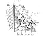
一方、リップ部形成用ブロック変形手段3は、第1リップ部形成用ブロック材21の内部に設けられている。このリップ部形成用ブロック変形手段3は、伸縮することによって第1リップ部形成用ブロック材21に弾性変形を起こさせて、リップ幅(リップ口25aの幅)の微調整を行うものである。そして、このリップ部形成用ブロック変形手段3は、複数のボルト式変形手段31と、レール部32と、減厚スリット33とを備えている。 On the other hand, the lip portion forming block deforming means 3 is provided inside the first lip portion forming
各ボルト式変形手段31は、図3に示すように、ボルト軸部311と、固定ヘッド312と、固定ナット313と、可動ナット314とから構成されている。固定ヘッド312は、ボルト軸部311の一端に設けられている。また、固定ナット313は、ボルト軸部311の略中間部に設けられている。また、可動ナット314は、ボルト軸部311の他端に設けられている。 As shown in FIG. 3, each bolt type deformation means 31 includes a
また、レール部32は、図1に示すように、第1リップ部形成用ブロック材21の上部内を、ブロック材21の長さ方向(ダイ1の長さ方向)Xと平行に貫通して設けられている。さらに詳しく説明すると、レール部32は、図2に示すように、上端がリップ部25を向くようにブロック材21のテーパ面214と平行に設けられている。 Further, as shown in FIG. 1, the
そして、レール部32内には、図1に示すように、複数のボルト式変形手段31が任意の位置に配置されている。具体的には、複数のボルト式変形手段31は、ブロック材21の長さ方向Xに並列している。そして、各ボルト式変形手段31は、図2に示すように一端がリップ部25へ向いており、ブロック材21の長さ方向Xにスライド移動可能に配置されている。 And in the
ここで、各ボルト式変形手段31とレール部32との関係について詳しく説明する。レール部32は、図3に示すように、メインレール321と、固定ヘッド用サブレール322と、可動ナット用サブレール323と、ボルト軸部用サブレール324とを備えている。 Here, the relationship between each bolt type deformation | transformation means 31 and the
メインレール321は、レール部32の中間部分を構成している。メインレール321の内部には、各ボルト式変形手段31のボルト軸部311及び固定ナット313が収容されている。また、このメインレール321は断面十字状に形成されている。メインレールの中間部分321aは、ボルト軸部311と直交する方向311xと平行に延在して形成されている。 The
そして、この中間部分321aはテーパ面214側が開口している。すなわち、図1にも示すように、第1リッブ部形成用ブロック材21の正面においてテーパ面214の部分には、操作用開口部32aが形成されている。この操作用開口部32aは、第1リッブ部形成用ブロックブ材21の長さ方向Xに平行に延在している。そして、この操作用開口部32aは、作業者が各ボルト式変形手段31を操作するために用いられる。 The
また、図3に示すように、固定ヘッド用サブレール322は、メインレール321の上側(リップ部25側)に設けられている。この固定ヘッド用サブレール322は、各ボルト式変形手段31の固定ヘッド312を収容するように断面角形状に形成されている。これを詳しく説明すると、固定ヘッド用サブレール322の両側の側面322aには、各ボルト式変形手段31の固定ヘッド312の側面312aがスライド移動可能に当接している。そして、固定ヘッド用サブレール322は、固定ヘッド312の上面312bや下面312cとの間に隙間322sが開くように形成されている。 As shown in FIG. 3, the fixed
また、可動ナット用サブレール323は、メインレール321の下側(リップ部25と反対側)に設けられている。この可動ナット用サブレール323は、各ボルト式変形手段31の可動ナット314を収容するように断面角形状に形成されている。これを詳しく説明すると、可動ナット用サブレール323の側面323aには、各ボルト式変形手段31の可動ナット314の側面314aがスライド移動可能に当接している。また、可動ナット用サブレール323は、可動ナット314の上面314bや下面314cとの間に隙間323sが開くように形成されている。 The
また、ボルト軸部用サブレール324は、可動ナット用サブレール323の下側に設けられている。このボルト軸部用サブレール324は、各ボルト式変形手段31のボルト軸部311の他端部311aを収容するように、可動ナット用サブレール323よりも狭い断面角形状に形成されている。さらに、ボルト軸部用サブレール324は、ボルト軸部311の他端部311aの周囲との間に隙間324sが開くように形成されている。 The
また、減厚スリット33は、レール部32の内側面に設けられている。具体的には、減厚スリット33は、メインレール321の中間部分321aの内側面321bに設けられている。そして、この減厚スリット33は、第1リップ部形成用ブロック材21の厚さが部分的に薄くなるように形成されている。詳しく説明すると、減厚スリット33は、メインレール321の内側面321bから流路23に向けてボルト軸部311と直交する方向311xに延在して形成されている。そして、先端部331が丸く形成されている。 Further, the
かかる構成において、リップ部形成用ブロック変形手段3によるコーティングダイ1のリップ幅の調整方法について説明する。 In this configuration, a method for adjusting the lip width of the coating die 1 by the lip portion forming block deforming means 3 will be described.
まず、作業者は、第1リップ部形成用ブロック材21の操作用開口部32aに手を入れてボルト式変形手段31の固定ナット313をつまみ、このボルト式変形手段31をブロック材21の長さ方向Xにスライド移動させてレール部32内の任意の位置に設置する。また、作業者は、他のボルト式変形手段31についても同様の操作を行って、各ボルト式変形手段31をレール部32内の各任意の位置に設置する。 First, the operator puts his hand into the operation opening 32 a of the first lip portion forming
そして、ダイ1のリップ幅25w(図4参照)を広げたい場合には、作業者が、各ボルト式変形手段31の固定ナット313をリップ口25aから視て左方向Rへ回してボルト軸部311を上方へ動かしていく。これにより、図4に示すように、固定ヘッド312の上面312bが固定ヘッド用サブレール322の上面322bを押し上げる。また、これに伴って可動ナット314は下方へ移動していき、可動ナット314の下面314cが可動ナット用サブレール323の下面323cを押し下げる。When the
その結果、第1リップ部形成用ブロック材21において、固定ヘッド312と可動ナット314との間の距離21aが、減厚スリット33の先端33aを中心にしてテーパ面214の上下方向214aと平行に広がるので、リップ幅25wが狭まる。 As a result, in the first lip portion forming
また、ダイ1のリップ幅25wを図3の状態から狭めたい場合には、作業者は、各ボルト式変形手段31の固定ナット313をリップ口25aから視て右方向Lへ回してボルト軸部311を下方へ動かしていく。これにより、図5に示すように、固定ヘッド312の下面312cが固定ヘッド用サブレール322の下面322cを押し下げる。また、これに伴って可動ナット314が上方へ移動していき、可動ナット314の上面314bが可動ナット用サブレール323の上面323bを押し上げる。When it is desired tonarrow the
その結果、第1リップ部形成用ブロック材21において、固定ヘッド312と可動ナット314との間の距離21aが、減厚スリット33の先端33aを中心にして、テーパ面214の上下方向214aと平行に縮むので、リップ幅25wが広がる。 As a result, in the first lip portion forming
このように、本実施の形態のコーティングダイ1では、各ボルト式変形手段31の固定ナット313を左右に回転させることにより、固定ヘッド312と可動ナット314との間隔を変えて、固定ヘッド用サブレール322の上面322b及び可動ヘッド用サブレール323の下面323cに対する付勢力、または固定ヘッド用サブレール322の下面322c及び可動ヘッド用サブレール323の上面323bに対する付勢力を調整することで、第1リップ部形成用ブロック材21を弾性変形させてリップ幅25wの微調整を行う。 As described above, in the coating die 1 of the present embodiment, the fixed
そして、本実施の形態のコーティングダイ1では、リップ幅25wの微調整を行うためのリップ部形成用ブロック変形手段3により、任意の位置で弾性変形を起こさせるようにしたので、リップ幅25wの微調整を任意の位置で行うことができる。なお、本実施の形態のコーティングダイ1では、リップ部形成用ブロック変形手段3を第1リップ部形成用ブロック材21のみに設けたが、第2リップ部形成用ブロック材22に設けても良いし、あるいは双方のブロック材21、22に設けても良い。 In the coating die 1 of the present embodiment, the lip portion forming block deformation means 3 for fine adjustment of the
また、本実施の形態のコーティングダイ1では、リップ部形成用ブロック変形手段3を、複数のボルト式変形手段31とレール部32とから構成したことにより、第1リップ部形成用ブロック材を全体的に弾性変形することが可能になる。よって、本実施の形態のコーティングダイ1は、リップ幅の微調整を容易に行うことができる。その結果、本実施の形態のコーティングダイ1は、基材に塗工液を塗布した際にその厚みを均一にすることができる。なお、本件発明のリップ部形成用ブロック変形手段は、少なくともリップ部形成用ブロック材の内部に設けられて、このブロック材を弾性変形させてリップ幅を微調整するものであれば良いので、本実施の形態のリップ部形成用ブロック変形手段3に限定しなくても良い。 In the coating die 1 of the present embodiment, the lip portion forming block deforming means 3 is composed of a plurality of bolt type deforming means 31 and
さらに、複数のボルト式変形手段31は、ダイ1の長さ方向Xと平行にスライド移動するように構成されている。このため、作業者は、各ボルト式変形手段31をレール部32内であればどの位置でも設置することが可能になり、さらに設置位置におけるブロック材21の弾性変形量の大きさを自由に設定することも可能になる。したがって、本実施の形態のコーティングダイ1は、複数のボルト式変形手段が所定位置に固定されているコーティングダイに比べて、ブロック材21全体の弾性変形の微調整を容易に行うことができる。よって、本実施の形態のコーティングダイ1は、リップ幅25wの微調整をさらに容易に行うことができる。その結果、本実施の形態のコーティングダイ1は、基材に塗工液を塗布した際にその厚みをより均一にすることができる。 Further, the plurality of bolt-type deformation means 31 are configured to slide in parallel with the length direction X of the
また、各ボルト式変形手段31の固定ヘッド312及び可動ナット313は、それぞれ固定ヘッド用サブレール322内及び可動ナット用サブレール323内に収容されているので、各ボルト式変形手段31の操作性を高めることができる。よって、本実施の形態のコーティングダイ1は、リップ幅25wの調整作業の効率を高めることができる。 Further, since the fixed
また、本実施の形態のコーティングダイ1においては、減厚スリット33により、第1リップ部形成用ブロック材21のリップ部25側を容易に弾性変形させることが可能になるので、リップ幅25wの調整作業の効率をさらに高めることができる。 Further, in the coating die 1 of the present embodiment, the
第2の実施の形態:
図6は、本件発明の第2の実施の形態を示すコーティングダイ101の断面図である。本実施の形態のコーティングダイ101では、第1の実施の形態で説明したコーティングダイ1(図2参照)と同じ部分には同じ符号を付し、異なる部分を中心にして説明する。なお、本実施の形態のコーティングダイ101では、第1の実施の形態で説明したボルト式変形手段31を省略している。Second embodiment:
FIG. 6 is a cross-sectional view of a coating die 101 showing a second embodiment of the present invention. In the coating die 101 of the present embodiment, the same portions as those of the coating die 1 (see FIG. 2) described in the first embodiment are denoted by the same reference numerals, and different portions are mainly described. In the coating die 101 of the present embodiment, the bolt type deformation means 31 described in the first embodiment is omitted.
本実施の形態のコーティングダイ101は、ダイ本体102が、第1の実施の形態のコーティングダイ1と同様に、第1リップ部形成用ブロック材121及び第2リップ部形成用ブロック材22を備えている。ここで、第1リップ部形成用ブロック材121は、第1の実施の形態で説明した第1リップ部形成用ブロック材21と同じ形状を備えている。しかし、この第1リップ部形成用ブロック材121は、レール部32の下側構成部1211が別部材から構成されている。この下側構成部1211は、メインレール321の下側部分と、可動ナット用サブレール323と、ボルト軸部用サブレール324とを含んで外側から切り欠いた部分である。また、この下側構成部1211は、第1リップ部形成用ブロック材121において下側構成部1211以外の部分である第1リップ部形成用ブロック材本体1212と同材質の別部材から形成されている。 In the coating die 101 of the present embodiment, the
これを詳しく説明すると、この下側構成部1211は、可動ナット用サブレール323の内側面323aから第1リップ部形成用ブロック材121の第2水平面213へ向けて切り欠いて形成される部分である。そして、この下側構成部1211は、ボルト軸部用サブレール324と第2水平面213との間に突出部1211aを有している。この突出部1211aは、各ボルト式変形手段31のボルト軸部311(図3参照)と直交する方向311xに突出している。This will be described in detail. The lower
また、第1リップ部形成用ブロック材本体1212には、下側構成部1211の突出部1211aを嵌め込むための蟻柄(嵌合溝)1212aが設けられている。そして、下側構成部1211の突出部1211aを蟻柄1212aに嵌め込んだ後に、二本のノックピン1213を下側構成部1211の左右端側からブロック材本体1212に打ち込むことで、下側構成部1211がブロック材本体1212に固定されている。 Further, the first lip portion forming
かかる構成において、本実施の形態のコーティングダイ101は、レール部32の下側構成部1211を、第1リップ部形成用ブロック材本体1212と同材質の別部材で形成したことにより、レール部32の上下の構成部分を別々に成型することが可能になる。したがって、本実施の形態のコーティングダイ101は、レール部32が一体成型可能なコーティングダイに比べて、レール部32の成型作業を容易に行うことができる。よって、本実施の形態のコーティングダイ101は、製造効率を高めることができる。また、本実施の形態のコーティングダイ101は、長さに関係なく製造可能である。 In such a configuration, the coating die 101 of the present embodiment has the
なお、コーティングダイのリップ部の形状は、第1の実施の形態や第2の実施の形態で示したリップ部25の形状に限定する必要はなく、例えば、図7に示すコーティングダイ401のリップ部425のようにダイ本体402から突出するような形状でも良い。 The shape of the lip portion of the coating die need not be limited to the shape of the
第3の実施の形態:
図8は、本件発明の第3の実施の形態を示すコーティングダイ501の正面図である。本実施の形態のコーティングダイ501では、第1の実施の形態で説明したコーティングダイ1(図1参照)と同じ部分には同じ符号を付し、異なる部分を中心にして説明する。Third embodiment:
FIG. 8 is a front view of a coating die 501 showing a third embodiment of the present invention. In the coating die 501 of the present embodiment, the same portions as those of the coating die 1 (see FIG. 1) described in the first embodiment are denoted by the same reference numerals, and different portions are mainly described.
本実施の形態のコーティングダイ501は、ダイ本体502が、第1の実施の形態のコーティングダイ1と同様に、第1リップ部形成用ブロック材521及び第2リップ部形成用ブロック材22を備えている。ここで、第1リップ部形成用ブロック材521の正面側には、テーパ面214に複数の挿入用開口部521aが設けられている。各挿入用開口部521aは離間して配置されており、操作用開口部32aと上下に交差するように設けられている。そして、各挿入用開口部521aは、ボルト式変形手段31をブロック材521の正面側からレール部32内に配置するために用いられる。 In the coating die 501 of the present embodiment, the
かかる構成において、本実施の形態のコーティングダイ501は、正面側に挿入用開口部521aを設けたことにより、製造に際して、ボルト式変形手段31をダイ501の左右側及び正面側からレール部32内に入れて配置することが可能になるので、各ボルト式変形手段31の配置作業を効率よく行うことができる。 In such a configuration, the coating die 501 of the present embodiment is provided with the
以上説明したように本件発明のコーティングダイは、リップ幅の微調整を任意の位置で行うことができる。よって、本件発明のコーティングダイは、コーティングダイの技術分野、ならびに押出しラミネート用Tダイの技術分野においても十分に利用することができる。 As described above, the coating die of the present invention can finely adjust the lip width at an arbitrary position. Therefore, the coating die of the present invention can be sufficiently used in the technical field of coating dies and the technical field of T-die for extrusion lamination.
1 コーティングダイ
3 リップ部形成用ブロック変形手段
21 第1リップ部形成用ブロック材
22 第2リップ部形成用ブロック材
23 流路
24 凹部
25 リップ部
25w リップ幅
31 ボルト式変形手段
32 レール部
33 減厚スリット
101 コーティングダイ
121 第1リップ部形成用ブロック材
211 底面
212 第1水平面
214 テーパ面
221 底面
222 第1水平面
224 テーパ面
311 ボルト軸部
312 固定ヘッド
313 固定ナット
314 可動ナット
322 固定ヘッド用サブレール
323 可動ナット用サブレール
401 コーティングダイ
425 リップ部
501 コーティングダイ
521 第1リップ部形成用ブロック材DESCRIPTION OF
Claims (4)
Translated fromJapanese前記リップ部形成用ブロック変形手段は、前記リップ部形成用ブロック材の内部に長さ方向に平行に設けられるレール部と、該レール部内に設けられ、任意の位置で伸縮自在な変形手段とから成り、
前記変形手段は、複数のボルト式変形手段から構成され、当該複数のボルト式変形手段の各々は、ボルト軸部と、該ボルト軸部の一端に設けられる固定ヘッドと、前記ボルト軸部の略中間部に設けられる固定ナットと、前記ボルト軸部の他端に設けられる可動ナットとを備え、当該固定ヘッドと当該可動ナットとが前記レール部の上面及び下面に当接し、且つ、当該レール部内でスライド移動可能なように配置され、
前記複数のボルト式変形手段は、各々の前記固定ナットを回転させることで前記固定ヘッドと前記可動ナットとの間隔を変えて前記レール部の上面と下面とに対する付勢力を調整し、前記リップ部形成用ブロック材を任意の位置で弾性変形させて前記リップ幅の微調整を行うものであり、
前記レール部は、前記複数のボルト式変形手段の前記固定ヘッドを収容する固定ヘッド用サブレールと、前記可動ナットを収容する可動ナット用サブレールとを備えることを特徴とするコーティングダイ。The lip portion for discharging the coating liquid to be applied to the surface of the substrate is composed ofa long first lip portion forming block material and a long second lip portion forming block material, and the first lip portion is formed. The block material for block and the block material for forming the second lip part each have a horizontal plane, and the horizontal plane is opposed to each other to form a flow path through which the coating liquid passes, At least one block material of the block material for forming the 1 lip portion and the block material for forming the second lip portion is capable of expanding and contracting at an arbitrary position in the inside thereof, causing elastic deformation of the block material, Acoating die having a lip forming block deformation means for fine adjustment,
The lip portion forming block deforming means comprises: a rail portion provided in parallel to the length direction inside the lip portion forming block material; and a deforming means provided in the rail portion and capable of expanding and contracting at an arbitrary position. Consisting of
The deformation means includes a plurality of bolt-type deformation means, and each of the plurality of bolt-type deformation means includes a bolt shaft portion, a fixed head provided at one end of the bolt shaft portion, and an abbreviation of the bolt shaft portion. A fixed nut provided at an intermediate portion and a movable nut provided at the other end of the bolt shaft portion, wherein the fixed head and the movable nut abut against the upper surface and the lower surface of the rail portion, and in the rail portion Is arranged so that it can slide.
The plurality of bolt-type deformation means adjust the urging force to the upper surface and the lower surface of the rail portion by changing the distance between the fixed head and the movable nut by rotating each fixed nut, and the lip portion Finely adjust the lip width by elastically deforming the forming block material at an arbitrary position,
The coating die, wherein the rail portion includes a fixed head subrail that accommodates the fixed heads of the plurality of bolt-type deformation means, and a movable nut subrail that accommodates the movable nut .
Priority Applications (1)
| Application Number | Priority Date | Filing Date | Title |
|---|---|---|---|
| JP2007075659AJP5095247B2 (en) | 2007-03-22 | 2007-03-22 | Coating die |
Applications Claiming Priority (1)
| Application Number | Priority Date | Filing Date | Title |
|---|---|---|---|
| JP2007075659AJP5095247B2 (en) | 2007-03-22 | 2007-03-22 | Coating die |
Publications (2)
| Publication Number | Publication Date |
|---|---|
| JP2008229560A JP2008229560A (en) | 2008-10-02 |
| JP5095247B2true JP5095247B2 (en) | 2012-12-12 |
Family
ID=39902987
Family Applications (1)
| Application Number | Title | Priority Date | Filing Date |
|---|---|---|---|
| JP2007075659AActiveJP5095247B2 (en) | 2007-03-22 | 2007-03-22 | Coating die |
Country Status (1)
| Country | Link |
|---|---|
| JP (1) | JP5095247B2 (en) |
Families Citing this family (11)
| Publication number | Priority date | Publication date | Assignee | Title |
|---|---|---|---|---|
| US10076853B2 (en) | 2010-12-30 | 2018-09-18 | United States Gypsum Company | Slurry distributor, system, and method for using same |
| AR084755A1 (en)* | 2010-12-30 | 2013-06-05 | United States Gypsum Co | DISTRIBUTOR AND METHOD OF DISTRIBUTION OF MILK |
| MY171701A (en) | 2010-12-30 | 2019-10-23 | United States Gypsum Co | Slurry distributor, system and method for using same |
| US9999989B2 (en) | 2010-12-30 | 2018-06-19 | United States Gypsum Company | Slurry distributor with a profiling mechanism, system, and method for using same |
| RU2638666C2 (en) | 2011-10-24 | 2017-12-15 | Юнайтед Стэйтс Джипсам Компани | Suspension distributor and method for its use |
| MX353809B (en) | 2011-10-24 | 2018-01-30 | United States Gypsum Co | Multi-piece mold and method of making slurry distributor. |
| PL2771158T3 (en) | 2011-10-24 | 2017-05-31 | United States Gypsum Company | Multiple-leg discharge boot for slurry distribution |
| AU2013231955A1 (en)* | 2012-03-16 | 2014-10-30 | Life Technologies Corporation | Systems and methods for loading liquid samples |
| US10059033B2 (en) | 2014-02-18 | 2018-08-28 | United States Gypsum Company | Cementitious slurry mixing and dispensing system with pulser assembly and method for using same |
| CN114100956B (en)* | 2020-08-26 | 2023-04-18 | 湖北万度光能有限责任公司 | Application of pressure sensor in slit coating system |
| CN116685412A (en)* | 2020-12-18 | 2023-09-01 | 富士胶片株式会社 | slot die |
Family Cites Families (6)
| Publication number | Priority date | Publication date | Assignee | Title |
|---|---|---|---|---|
| JP2780016B2 (en)* | 1995-02-10 | 1998-07-23 | 井上金属工業株式会社 | Coating equipment |
| JP2784899B2 (en)* | 1995-03-14 | 1998-08-06 | 井上金属工業株式会社 | Coating equipment |
| JPH09131561A (en)* | 1995-11-09 | 1997-05-20 | Toray Ind Inc | Coating device, coating method, producing device for color filter and its production |
| JPH10146555A (en)* | 1996-11-20 | 1998-06-02 | Fujimori Kogyo Kk | Die coater and method for adjusting position of die used therein |
| JP2001286806A (en)* | 2000-04-11 | 2001-10-16 | Inoue Kinzoku Kogyo Co Ltd | Coating device |
| JP2004188321A (en)* | 2002-12-11 | 2004-07-08 | Tokyo Electron Ltd | Air jetting apparatus and air jetting width adjustment method |
- 2007
- 2007-03-22JPJP2007075659Apatent/JP5095247B2/enactiveActive
Also Published As
| Publication number | Publication date |
|---|---|
| JP2008229560A (en) | 2008-10-02 |
Similar Documents
| Publication | Publication Date | Title |
|---|---|---|
| JP5095247B2 (en) | Coating die | |
| JP4283732B2 (en) | Rubber molding equipment | |
| KR101745024B1 (en) | Gasket structure of fuel cell separator having improved air thightness | |
| EP1967299B1 (en) | Apparatus for and method of extrusion-molding a hollow material | |
| JP2008178818A (en) | Slit die and shim | |
| WO2019069451A1 (en) | Mold platen, mold clamping device, injection molding device | |
| CN114682439A (en) | Staggered lip coating die head | |
| US20090168444A1 (en) | Motor and guiding structure thereof | |
| JP2013216069A (en) | Die unit | |
| JP4592450B2 (en) | Die head and slit gap adjusting method | |
| JP2015223843A (en) | Multi-manifold extrusion die with deckle system and method of using the same | |
| JP6019251B2 (en) | Flat die for extrusion molding and film forming method | |
| JP2005219254A (en) | Cap of extruder and method for altering size thereof | |
| RU2662524C2 (en) | Spinning jet for the film manufacturing by extrusion | |
| JP6147613B2 (en) | Rubber molding equipment | |
| WO2010101531A1 (en) | Assembly and method for improved singulation | |
| KR100414954B1 (en) | Length adjustable moving mold | |
| JP4370742B2 (en) | Bushing plate manufacturing method | |
| CN216680367U (en) | Rotary bracket jig for double-sided drilling of tubular rib plate | |
| KR100768435B1 (en) | Molding dies of sheet material | |
| US20030080462A1 (en) | Extrusion die with horizontal and vertical extrudate opening adjustment | |
| KR20100003508U (en) | Mold Assembly | |
| JP5265901B2 (en) | Mold | |
| JP6538327B2 (en) | Extrusion die with deckel system and method of using the same | |
| KR20110074019A (en) | Lower block and mold unit for molding electronic parts including the same |
Legal Events
| Date | Code | Title | Description |
|---|---|---|---|
| A621 | Written request for application examination | Free format text:JAPANESE INTERMEDIATE CODE: A621 Effective date:20091214 | |
| A977 | Report on retrieval | Free format text:JAPANESE INTERMEDIATE CODE: A971007 Effective date:20111027 | |
| A131 | Notification of reasons for refusal | Free format text:JAPANESE INTERMEDIATE CODE: A131 Effective date:20120620 | |
| A521 | Request for written amendment filed | Free format text:JAPANESE INTERMEDIATE CODE: A523 Effective date:20120816 | |
| TRDD | Decision of grant or rejection written | ||
| A01 | Written decision to grant a patent or to grant a registration (utility model) | Free format text:JAPANESE INTERMEDIATE CODE: A01 Effective date:20120906 | |
| A01 | Written decision to grant a patent or to grant a registration (utility model) | Free format text:JAPANESE INTERMEDIATE CODE: A01 | |
| A61 | First payment of annual fees (during grant procedure) | Free format text:JAPANESE INTERMEDIATE CODE: A61 Effective date:20120919 | |
| R150 | Certificate of patent or registration of utility model | Free format text:JAPANESE INTERMEDIATE CODE: R150 Ref document number:5095247 Country of ref document:JP Free format text:JAPANESE INTERMEDIATE CODE: R150 | |
| FPAY | Renewal fee payment (event date is renewal date of database) | Free format text:PAYMENT UNTIL: 20150928 Year of fee payment:3 | |
| R250 | Receipt of annual fees | Free format text:JAPANESE INTERMEDIATE CODE: R250 | |
| R250 | Receipt of annual fees | Free format text:JAPANESE INTERMEDIATE CODE: R250 | |
| R250 | Receipt of annual fees | Free format text:JAPANESE INTERMEDIATE CODE: R250 | |
| R250 | Receipt of annual fees | Free format text:JAPANESE INTERMEDIATE CODE: R250 | |
| R250 | Receipt of annual fees | Free format text:JAPANESE INTERMEDIATE CODE: R250 | |
| R250 | Receipt of annual fees | Free format text:JAPANESE INTERMEDIATE CODE: R250 | |
| R250 | Receipt of annual fees | Free format text:JAPANESE INTERMEDIATE CODE: R250 | |
| R250 | Receipt of annual fees | Free format text:JAPANESE INTERMEDIATE CODE: R250 | |
| R250 | Receipt of annual fees | Free format text:JAPANESE INTERMEDIATE CODE: R250 | |
| R250 | Receipt of annual fees | Free format text:JAPANESE INTERMEDIATE CODE: R250 | |
| R250 | Receipt of annual fees | Free format text:JAPANESE INTERMEDIATE CODE: R250 |