JP5094140B2 - Member joint structure - Google Patents
Member joint structureDownload PDFInfo
- Publication number
- JP5094140B2 JP5094140B2JP2007013988AJP2007013988AJP5094140B2JP 5094140 B2JP5094140 B2JP 5094140B2JP 2007013988 AJP2007013988 AJP 2007013988AJP 2007013988 AJP2007013988 AJP 2007013988AJP 5094140 B2JP5094140 B2JP 5094140B2
- Authority
- JP
- Japan
- Prior art keywords
- end portion
- auxiliary member
- auxiliary
- main
- main member
- Prior art date
- Legal status (The legal status is an assumption and is not a legal conclusion. Google has not performed a legal analysis and makes no representation as to the accuracy of the status listed.)
- Active
Links
Images


Classifications
- B—PERFORMING OPERATIONS; TRANSPORTING
- B23—MACHINE TOOLS; METAL-WORKING NOT OTHERWISE PROVIDED FOR
- B23K—SOLDERING OR UNSOLDERING; WELDING; CLADDING OR PLATING BY SOLDERING OR WELDING; CUTTING BY APPLYING HEAT LOCALLY, e.g. FLAME CUTTING; WORKING BY LASER BEAM
- B23K20/00—Non-electric welding by applying impact or other pressure, with or without the application of heat, e.g. cladding or plating
- B23K20/12—Non-electric welding by applying impact or other pressure, with or without the application of heat, e.g. cladding or plating the heat being generated by friction; Friction welding
- B23K20/122—Non-electric welding by applying impact or other pressure, with or without the application of heat, e.g. cladding or plating the heat being generated by friction; Friction welding using a non-consumable tool, e.g. friction stir welding
- B23K20/1265—Non-butt welded joints, e.g. overlap-joints, T-joints or spot welds
- B—PERFORMING OPERATIONS; TRANSPORTING
- B23—MACHINE TOOLS; METAL-WORKING NOT OTHERWISE PROVIDED FOR
- B23K—SOLDERING OR UNSOLDERING; WELDING; CLADDING OR PLATING BY SOLDERING OR WELDING; CUTTING BY APPLYING HEAT LOCALLY, e.g. FLAME CUTTING; WORKING BY LASER BEAM
- B23K20/00—Non-electric welding by applying impact or other pressure, with or without the application of heat, e.g. cladding or plating
- B23K20/12—Non-electric welding by applying impact or other pressure, with or without the application of heat, e.g. cladding or plating the heat being generated by friction; Friction welding
- B23K20/122—Non-electric welding by applying impact or other pressure, with or without the application of heat, e.g. cladding or plating the heat being generated by friction; Friction welding using a non-consumable tool, e.g. friction stir welding
- B23K20/1245—Non-electric welding by applying impact or other pressure, with or without the application of heat, e.g. cladding or plating the heat being generated by friction; Friction welding using a non-consumable tool, e.g. friction stir welding characterised by the apparatus
- B23K20/126—Workpiece support, i.e. backing or clamping
- B—PERFORMING OPERATIONS; TRANSPORTING
- B23—MACHINE TOOLS; METAL-WORKING NOT OTHERWISE PROVIDED FOR
- B23K—SOLDERING OR UNSOLDERING; WELDING; CLADDING OR PLATING BY SOLDERING OR WELDING; CUTTING BY APPLYING HEAT LOCALLY, e.g. FLAME CUTTING; WORKING BY LASER BEAM
- B23K2101/00—Articles made by soldering, welding or cutting
- B23K2101/04—Tubular or hollow articles
- B23K2101/045—Hollow panels
- B—PERFORMING OPERATIONS; TRANSPORTING
- B23—MACHINE TOOLS; METAL-WORKING NOT OTHERWISE PROVIDED FOR
- B23K—SOLDERING OR UNSOLDERING; WELDING; CLADDING OR PLATING BY SOLDERING OR WELDING; CUTTING BY APPLYING HEAT LOCALLY, e.g. FLAME CUTTING; WORKING BY LASER BEAM
- B23K2103/00—Materials to be soldered, welded or cut
- B23K2103/18—Dissimilar materials
- B23K2103/20—Ferrous alloys and aluminium or alloys thereof
Landscapes
- Engineering & Computer Science (AREA)
- Mechanical Engineering (AREA)
- Pressure Welding/Diffusion-Bonding (AREA)
Description
Translated fromJapanese本発明は部材接合構造に関するものである。 The present invention relates to a member joining structure.
接合すべき部材を溶融させずに相互に接続する方法として摩擦撹拌接合がある(例えば、特許文献1参照)。 Friction stir welding is a method for connecting members to be joined together without melting them (see, for example, Patent Document 1).
この技法では、被接合部材を重ね合わせた被接合物を、裏当て部材である支持ツールに載せたうえ、被接合物に接合ツールを回転させながら押し付け、摩擦熱と塑性流動により軟化した材料を撹拌して同化させる。 In this technique, the object to be joined is placed on a support tool that is a backing member, and the material that has been softened by frictional heat and plastic flow is pressed against the object while rotating the joining tool. Agitate to assimilate.
次いで、接合ツールを被接合物から離して材料が同化した部位を硬化させ、被接合部材を相互に接合する。 Next, the part to which the material is assimilated is cured by separating the joining tool from the object to be joined, and the members to be joined are joined to each other.
接合ツールは、円柱状のショルダ部と、当該ショルダ部に同軸に連なり且つツール先端へ向けて突出する短円筒状でショルダ部よりも外径が小さいピン部とを備えている。 The joining tool includes a columnar shoulder portion and a pin portion that is coaxial with the shoulder portion and projects toward the tip of the tool and has a smaller outer diameter than the shoulder portion.
また、アルミニウム合金を素材とした中空押し出し形材を二つ並べたうえ、この形材を摩擦撹拌接合によって一体化して構造体を製作する手法も既に提案されている(例えば、特許文献2参照)。
二つの面板の間をリブによって接続した断面を呈する形材は、面板とリブの共同によりこれら単体を上回る剛性を発揮するが、時として形材の剛性を局所的に強めることが要求される。 A shape member having a cross section in which two face plates are connected by ribs exhibits rigidity exceeding that of the simple substance due to the joint of the face plate and the ribs, but sometimes it is required to locally increase the rigidity of the shape member.
この場合、二つの面板の間にリブを追加するという手立てが考えられるが、リブは形材の全長にわたって存在するため、結果的に形材の重量が増えてしまうし、コストアップにもなる。 In this case, it is conceivable to add a rib between the two face plates. However, since the rib exists over the entire length of the shape member, as a result, the weight of the shape member increases and the cost increases.
本発明は上述した実情に鑑みてなしたもので、形材の補強に適した部材接合構造を提供することを目的としている。 The present invention has been made in view of the above-described circumstances, and an object thereof is to provide a member joining structure suitable for reinforcing a shape member.
上記目的を達成するため、請求項1に記載の発明では、第1の個所と第2の個所のそれぞれに正対する孔が穿設してある主部材と、先端部分が主部材の第2の個所の孔に入り且つ基端部分が主部材の第1の個所の孔に入った補助部材と、当該補助部材の基端部分、あるいは先端部分のいずれかに外嵌して主部材に当接する付加部材とを備え、前記補助部材の先端部分及び基端部分の双方を、摩擦熱と塑性流動により前記主部材の第1、第2の個所、並びに付加部材に同化させた構成を採る。 In order to achieve the above object, according to the first aspect of the present invention, there is provided a main member in which a hole facing each of the first portion and the second portion is formed, and a tip portion is a second member of the main member. The auxiliary member that enters the hole at the location and the base end portion enters the hole at the first location of the main member and the base member or the distal end portion of the auxiliary member are externally fitted to contact the main member. An additional member is provided, and both the distal end portion and the proximal end portion of the auxiliary member are assimilated to the first and second portions of the main member and the additional member by frictional heat and plastic flow.
請求項2に記載の発明では、第1の個所と第2の個所のそれぞれに正対する孔が穿設してある主部材と、先端部分が主部材の第2の個所の孔に入り且つ基端部分が主部材の第1の個所の孔に入った補助部材と、当該補助部材の基端部分、あるいは先端部分のいずれかに外嵌して主部材に当接する付加部材とを備え、前記補助部材の先端部分及び基端部分の双方を、摩擦熱と塑性流動により前記主部材の第1、第2の個所に同化させて、付加部材を厚み方向に挟むように形作った構成を採る。 In the second aspect of the present invention, the main member in which holes facing each of the first part and the second part are formed, and the tip part enters the hole in the second part of the main member and An auxiliary member having an end portion that enters a hole in the first portion of the main member, and an additional member that is externally fitted to either the proximal end portion or the distal end portion of the auxiliary member and contacts the main member, Both the front end portion and the base end portion of the auxiliary member are assimilated into the first and second portions of the main member by frictional heat and plastic flow, and the additional member is sandwiched in the thickness direction.
請求項3に記載の発明では、第1の個所と第2の個所のそれぞれに正対する孔が穿設してある主部材と、先端部分が主部材の第2の個所の孔に入り且つ基端部分が主部材の第1の個所の孔に入った補助部材と、当該補助部材の基端部分に外嵌して主部材に当接する第1の付加部材と、前記補助部材の先端部分に外嵌して主部材に当接する第2の付加部材とを備え、前記補助部材の先端部分及び基端部分の双方を、摩擦熱と塑性流動により前記主部材の第1、第2の個所、並びに第1、第2の付加部材に同化させた構成を採る。 In the invention according to
請求項4に記載の発明では、第1の個所と第2の個所のそれぞれに正対する孔が穿設してある主部材と、先端部分が主部材の第2の個所の孔に入り且つ基端部分が主部材の第1の個所の孔に入った補助部材と、当該補助部材の基端部分に外嵌して主部材に当接する第1の付加部材と、前記補助部材の先端部分に外嵌して主部材に当接する第2の付加部材とを備え、前記補助部材の先端部分及び基端部分の双方を、摩擦熱と塑性流動により前記主部材の第1、第2の個所に同化させて、第1、第2の付加部材を厚み方向に挟むように形作った構成を採る。 In the invention according to
本発明の部材接合構造によれば、摩擦熱と塑性流動により補助部材の基端部分と先端部分を主部材に同化させているので、主部材の剛性を局所的に高めると共に、主部材の重量増加を抑えることができ、しかも、主部材の剛性向上と同時に付加部材の取り付けが完了するので、部材組付工程を減らすことができるという優れた効果を奏し得る。 According to the member joining structure of the present invention, the proximal end portion and the distal end portion of the auxiliary member are assimilated to the main member by frictional heat and plastic flow, so that the rigidity of the main member is locally increased and the weight of the main member is increased. The increase can be suppressed, and since the attachment of the additional member is completed simultaneously with the improvement of the rigidity of the main member, an excellent effect of reducing the member assembling step can be obtained.
以下、本発明の実施の形態を図面に基づき説明する。 Hereinafter, embodiments of the present invention will be described with reference to the drawings.
図1は部材接合構造の参考例であり、凹部1を有する裏当て部材2と、短円柱状のピン部3を円柱状のショルダ部4の先端面に同軸に連ねた接合ツール5とを用いて、矩形断面の中空形材である主部材6に、丸棒状の補助部材7を接合する。 FIG. 1 is a reference example of a member joining structure, and uses a backing member 2 having a recess 1 and a
主部材6と補助部材7は、アルミニウム合金を素材とし、裏当て部材2と接合ツール5は、アルミニウム合金よりも硬く且つ軟化温度が高い鋼を素材としている。 The
主部材6の第1の個所8aとそれに向き合う第2の個所8bのそれぞれに孔9a,9bを穿設し、裏当て部材2の凹部1で補助部材7の基端部分を受け、第1の個所8aの孔9aに補助部材7の基端部分が入り且つ第2の個所8bの孔9bに補助部材7の先端部分が入るように主部材6を配置したうえ、接合ツール5を補助部材7の先端部分に相対させる(図1(a)参照)。
孔9a,9bの形状は、補助部材7が丸棒状であれば、ドリルで穿設した丸孔でよく、補助部材7が角棒状、もしくは板状である場合には、それに見合った形の孔9a,9bを機械加工などで各個所8a,8bに穿設することになる。 The shape of the
接合ツール5を回転させながら、ピン部3を補助部材7の先端に押し付けると、摩擦熱と塑性流動により軟化したこの部位にピン部3が徐々にめり込む。 When the
やがて、接合ツール5のショルダ部4の端面が、補助部材7の先端と主部材6の第2の個所8bに押し付けられ、当該第2の個所8bも摩擦熱と塑性流動により軟化して、接合ツール5のピン部3の周囲に、主部材6の第2の個所8bと補助部材7の先端部分に由来する材料の同化層10が軟化した状態で生じる(図1(b)参照)。 Eventually, the end face of the
回転している接合ツール5のピン部3を丸棒状の補助部材7の先端部分に押し付けると、初めのうちは補助部材7も周方向へ回ることがある。 When the
この補助部材7の回動は材料の軟化に伴って収まるが、クランプのような機械的手段を用いて補助部材7の回動を抑えるという手法も採れる。 Although the rotation of the
接合ツール5の押圧力は、補助部材7を介して裏当て部材2に伝わるので、主部材6の第1の個所8aと第2の個所8bの間にある第3の個所8cや第4の個所8dには座屈変形が生じない。 Since the pressing force of the
この後、接合ツール5を主部材6及び補助部材7から引き離して、塑性流動部位である同化層10を硬化させ、補助部材7の基端部分を裏当て部材2から取り外したうえ、主部材6及び補助部材7を逆向きにし、前記同化層10を裏当て部材(図示せず)により受け、接合ツール5を補助部材7の基端部分に相対させる。 Thereafter, the
接合ツール5を回転させながら、ピン部3を補助部材7の基端に押し付けると、摩擦熱と塑性流動により軟化したこの部位にピン部3が徐々にめり込む。 When the
やがて、接合ツール5のショルダ部4の端面が、補助部材7の基端と主部材6の第1の個所8aに押し付けられ、当該第1の個所8aも摩擦熱と塑性流動により軟化して、接合ツール5のピン部3の周囲に、主部材6の第1の個所8aと補助部材7の基端部分に由来する材料の同化層11が軟化した状態で生じる(図1(c)参照)。 Eventually, the end surface of the
既に同化層10が硬化して補助部材7の先端部分が主部材6の第2の個所8bに一体化しているため、回転している接合ツール5のピン部3を丸棒状の補助部材7の基端部分に押し付けても、補助部材7は周方向へ回らない。 Since the
接合ツール5の押圧力は、補助部材7を介して第2の個所8bに伝わるので、主部材6の第1の個所8aと第2の個所8bの間にある第3の個所8cや第4の個所8dには座屈変形が生じない。 Since the pressing force of the
この後、接合ツール5を主部材6及び補助部材7から引き離して、塑性流動部位である同化層11を硬化させる(図1(d)参照)。 Thereafter, the
すなわち、主部材6の第2の個所8bに補助部材7の先端部分が一体化し、主部材6の第1の個所8aに補助部材7の基端部分が一体化して、主部材6の剛性が局所的に高まることになる。 That is, the distal end portion of the
また、接合ツール5のピン部3がめり込んだあとの形作られた補助部材7の先端部分の穴12と基端部分の穴13は、雌ねじ加工を施せば別部材のボルト締結に利用できる。 Further, the
上述した事例では、補助部材7の先端部分を主部材6の第2の個所8bと一体化させた後に、補助部材7の基端部分を主部材6の第1の個所8aと一体化させているが、これと逆に、補助部材7の基端部分を主部材6の第1の個所8aと一体化させた後に、補助部材7の先端部分を主部材6の第2の個所8bと一体化させるという手順を採っても何ら差し支えない。 In the case described above, after the distal end portion of the
図2は部材接合構造の別の参考例であり、図中、図1と同一の符号を付した部分は同一物を表わしている。 FIG. 2 shows another reference example of the member joining structure. In the figure, the parts denoted by the same reference numerals as those in FIG. 1 represent the same items.
この例では、平らな裏当て部材14と、先に述べた接合ツール5とを用いて、矩形断面の中空形材である主部材6に、その第1の個所8aに当接するフランジ15を基端部分に有する丸棒状の補助部材16を接合する。 In this example, by using the
補助部材16は、アルミニウム合金を素材とし、裏当て部材14は、アルミニウム合金よりも硬く且つ軟化温度が高い鋼を素材としている。 The
裏当て部材14で補助部材16のフランジ15を受け、第1の個所8aの孔9aに補助部材16の基端部分が入り且つ第2の個所8bの孔9bに補助部材16の先端部分が入るように主部材6を配置してフランジ15に第1の個所8aを載せ、接合ツール5を補助部材16の先端部分に相対させる(図2(a)参照)。 The
接合ツール5を回転させながら、ピン部3を補助部材16の先端に押し付けると、摩擦熱と塑性流動により軟化したこの部位にピン部3が徐々にめり込む。 When the
やがて、接合ツール5のショルダ部4の端面が、補助部材16の先端と主部材6の第2の個所8bに押し付けられ、当該第2の個所8bも摩擦熱と塑性流動により軟化して、接合ツール5のピン部3の周囲に、主部材6の第2の個所8bと補助部材16の先端部分に由来する材料の同化層17が軟化した状態で生じる(図2(b)参照)。 Eventually, the end surface of the
回転している接合ツール5のピン部3を丸棒状の補助部材16の先端部分に押し付けると、初めのうちは補助部材16も周方向へ回ることがある。 When the
この補助部材16の回動は材料の軟化に伴って収まるが、クランプのような機械的手段を用いて補助部材16の回動を抑えるという手法も採れる。 The rotation of the
接合ツール5の押圧力は、補助部材16を介して裏当て部材14に伝わるので、主部材6の第1の個所8aと第2の個所8bの間にある第3の個所8cや第4の個所8dには座屈変形が生じない。 Since the pressing force of the
この後、接合ツール5を主部材6及び補助部材16から引き離して、塑性流動部位である同化層17を硬化させ、補助部材16の基端部分を裏当て部材14から取り外したうえ、主部材6及び補助部材16を逆向きにし、前記同化層17を裏当て部材(図示せず)により受け、接合ツール5を補助部材16の基端部分に相対させる。 Thereafter, the joining
接合ツール5を回転させながら、ピン部3を補助部材16の基端に押し付けると、摩擦熱と塑性流動により軟化したこの部位にピン部3が徐々にめり込む。 When the
やがて、接合ツール5のショルダ部4の端面が、補助部材16のフランジ15と主部材6の第1の個所8aに押し付けられ、当該第1の個所8aも摩擦熱と塑性流動により軟化して、接合ツール5のピン部3の周囲に、主部材6の第1の個所8aと補助部材16のフランジ15に由来する材料の同化層18が軟化した状態で生じる(図2(c)参照)。 Eventually, the end face of the
既に同化層17が硬化して補助部材16の先端部分が主部材6の第2の個所8bに一体化しているため、回転している接合ツール5のピン部3を丸棒状の補助部材16の基端部分に押し付けても、補助部材16は周方向へ回らない。 Since the
接合ツール5の押圧力は、補助部材16を介して第2の個所8bに伝わるので、主部材6の第1の個所8aと第2の個所8bの間にある第3の個所8cや第4の個所8dには座屈変形が生じない。 Since the pressing force of the
この後、接合ツール5を主部材6及び補助部材16から引き離して、塑性流動部位である同化層18を硬化させる(図2(d)参照)。 Thereafter, the joining
すなわち、主部材6の第2の個所8bに補助部材16の先端部分が一体化し、主部材6の第1の個所8aに補助部材16の基端部分が一体化して、主部材6の剛性が局所的に高まることになる。 That is, the distal end portion of the
また、接合ツール5のピン部3がめり込んだあとの形作られた補助部材16の先端部分の穴19と基端部分の穴20は、雌ねじ加工を施せば別部材のボルト締結に利用できる。 Further, the
上述した事例では、補助部材16の先端部分を主部材6の第2の個所8bと一体化させた後に、補助部材16の基端部分を主部材6の第1の個所8aと一体化させているが、これと逆に、補助部材16の基端部分を主部材6の第1の個所8aと一体化させた後に、補助部材16の先端部分を主部材6の第2の個所8bと一体化させるという手順を採っても何ら差し支えない。 In the case described above, after the distal end portion of the
図3は部材接合構造の更に別の参考例であり、図中、図1と同一の符号を付した部分は同一物を表わしている。 FIG. 3 shows still another reference example of the member joining structure. In the figure, the portions denoted by the same reference numerals as those in FIG. 1 represent the same items.
この例では、先に説明した図1(b)の工程を経て同化層10が硬化した後、主部材6及び補助部材7を逆向きにし、接合ツール5を補助部材7の基端部分に相対させたうえ、付加部材21を補助部材7に外嵌し且つ主部材6の第1の個所8aに載るように配置する。 In this example, after the
この付加部材21は、アルミニウム合金を素材としている。 The
接合ツール5を回転させながら、ピン部3を補助部材7の基端に押し付けると、摩擦熱と塑性流動により軟化したこの部位にピン部3が徐々にめり込む。 When the
やがて、接合ツール5のショルダ部4の端面が、補助部材7の基端と付加部材21に押し付けられ、当該付加部材21や主部材6の第1の個所8aも摩擦熱と塑性流動により軟化して、接合ツール5のピン部3の周囲に、付加部材21と主部材6の第1の個所8aと補助部材7の基端部分に由来する材料の同化層22が軟化した状態で生じる(図3(a)参照)。 Eventually, the end surface of the
この後、接合ツール5を主部材6、補助部材7、及び付加部材21から引き離して、塑性流動部位である同化層22を硬化させる(図3(b)参照)。 Thereafter, the joining
すなわち、主部材6の第2の個所8bに補助部材7の先端部分が一体化し、主部材6の第1の個所8aに補助部材7の基端部分と付加部材21が一体化して、主部材6の剛性が局所的に高まり、これと同時に付加部材21の装着も完了するため、部材組付工程が減ることになる。 That is, the distal end portion of the
また、接合ツール5のピン部3がめり込んだあとの形作られた補助部材7の先端部分の穴12と基端部分の穴23は、雌ねじ加工を施せば別部材のボルト締結に利用できる。 Further, the
上述した事例では、補助部材7の先端部分を主部材6の第2の個所8bと一体化させた後に、補助部材7の基端部分を主部材6の第1の個所8aや付加部材21に一体化させているが、これと逆に、補助部材16の基端部分を主部材6の第1の個所8aや付加部材21に一体化させた後に、補助部材7の先端部分を主部材6の第2の個所8bと一体化させるという手順を採っても何ら差し支えない。 In the case described above, after the distal end portion of the
この他に、付加部材21を図1(a)や図2(a)の主部材6の第2の個所8bに当接するように補助部材7の先端部分に外嵌させ、摩擦撹拌接合の手法により補助部材7,16及び主部材6との一体化を図ることもできる。 In addition, the
更に、付加部材21を図2(a)の補助部材16に予め外嵌させておき、主部材6の第1の個所8aと補助部材16のフランジ15で付加部材21を挟み、摩擦撹拌接合の手法により補助部材16及び主部材6との一体化を図ることもできる。 Further, the
図4は本発明の部材接合構造の第1の例であり、図中、図1と同一の符号を付した部分は同一物を表わしている。 FIG. 4 shows a first example of the member joining structure according to the present invention. In the figure, the same reference numerals as those in FIG. 1 denote the same parts.
この例では、先に説明した図1(b)の工程を経て同化層10が硬化した後、主部材6及び補助部材7を逆向きにし、接合ツール5を補助部材7の基端部分に相対させたうえ、付加部材24を補助部材7に外嵌し且つ主部材6の第1の個所8aに載るように配置する。 In this example, after the
この付加部材24は、鋼を素材としている。 The
接合ツール5を回転させながら、ピン部3を補助部材7の基端に押し付けると、摩擦熱と塑性流動により軟化したこの部位にピン部3が徐々にめり込む。 When the
やがて、接合ツール5のショルダ部4の端面が、補助部材7の基端に押し付けられ、主部材6の第1の個所8aも摩擦熱と塑性流動により軟化して、接合ツール5のピン部3の周囲に、主部材6の第1の個所8aと補助部材7の基端部分に由来する材料の同化層25が軟化した状態で、付加部材24を部材厚み方向に挟むように生じる(図4(a)参照)。 Eventually, the end surface of the
この後、接合ツール5を主部材6、補助部材7、及び付加部材24から引き離して、塑性流動部位である同化層25を硬化させる(図4(b)参照)。 Thereafter, the joining
すなわち、主部材6の第2の個所8bに補助部材7の先端部分が一体化し、主部材6の第1の個所8aに補助部材7の基端部分が一体化して、主部材6の剛性が局所的に高まり、これと同時に付加部材24の装着も完了するため、部材組付工程が減ることになる。 That is, the distal end portion of the
また、接合ツール5のピン部3がめり込んだあとの形作られた補助部材7の先端部分の穴12と基端部分の穴26は、雌ねじ加工を施せば別部材のボルト締結に利用できる。 Further, the
上述した事例では、補助部材7の先端部分を主部材6の第2の個所8bと一体化させた後に、補助部材7の基端部分を主部材6の第1の個所8aと一体化させて付加部材24を組み付けているが、これと逆に、補助部材16の基端部分を主部材6の第1の個所8aに一体化させて付加部材24を組み付けた後に、補助部材7の先端部分を主部材6の第2の個所8bと一体化させるという手順を採っても何ら差し支えない。 In the case described above, after the distal end portion of the
この他に、付加部材24を図1(a)や図2(a)の主部材6の第2の個所8bに当接するように補助部材7の先端部分に外嵌させ、摩擦撹拌接合の手法により主部材6に組み付けることもできる。 In addition to this, the
更に、付加部材21を図2(a)の補助部材16に予め外嵌させておき、主部材6の第1の個所8aと補助部材16のフランジ15で付加部材21を挟み、摩擦撹拌接合の手法により主部材6に組み付けることもできる。 Further, the
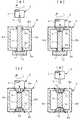
図5は本発明の部材接合構造の第2の例であり、図中、図3と同一の符号を付した部分は同一物を表わしている。 FIG. 5 shows a second example of the member joining structure according to the present invention. In the figure, the same reference numerals as those in FIG. 3 denote the same parts.
この例では、主部材6に付加部材21を装着するのとは別に、アルミニウム合金を素材とする付加部材27を補助部材7の先端部分に外嵌させ、接合ツール5によって補助部材7の先端部分と付加部材27と主部材6の第2の個所8bに由来する材料の同化層28を形作り、この後、同化層28を硬化させて付加部材27を主部材6及び補助部材7に装着する。 In this example, apart from mounting the
よって、主部材6の剛性を局所的に高める際に、付加部材21,27の装着も完了し、部材組付工程が減ることになる。 Therefore, when the rigidity of the
また、接合ツール5のピン部3がめり込んだあとに形作られた補助部材7の先端部分の穴29と基端部分の穴23は、雌ねじ加工を施せば別部材のボルト締結に利用できる。 Further, the
図6は本発明の部材接合構造の第3の例であり、図中、図4と同一の符号を付した部分は同一物を表わしている。 FIG. 6 shows a third example of the member joining structure according to the present invention. In the figure, the same reference numerals as those in FIG. 4 denote the same parts.
この例では、主部材6に付加部材24を装着するのとは別に、鋼を素材とする付加部材30を補助部材7の先端部分に外嵌させ、接合ツール5によって補助部材7の先端部分と主部材6の第2の個所8bに由来する材料の同化層31を形作り、この後、同化層31を硬化させて付加部材30を主部材6及び補助部材7に装着する。 In this example, apart from mounting the
よって、主部材6の剛性を局所的に高める際に、付加部材24,30の装着も完了し、部材組付工程が減ることになる。 Therefore, when the rigidity of the
また、接合ツール5のピン部3がめり込んだあとに形作られた補助部材7の先端部分の穴32と基端部分の穴26は、雌ねじ加工を施せば別部材のボルト締結に利用できる。 Further, the
図7は本発明の部材接合構造に関連する施工手順の他の例であり、図中、図1と同一の符号を付した部分は同一物を表わしている。 FIG. 7 shows another example of the construction procedure related to the member joining structure of the present invention. In the figure, the parts denoted by the same reference numerals as those in FIG. 1 represent the same items.
この例では、接合ツール5を回転させながら、ピン部3を補助部材7の先端に押し付け、摩擦熱と塑性流動により軟化した補助部材7の材料を変形させたうえ、これに同化し得るように主部材6の第2の個所8bの材料も摩擦熱と塑性流動により軟化させる工程に並行して、別の接合ツール5を回転させながら、ピン部3を補助部材7の基端に押し付け、摩擦熱と塑性流動により軟化した補助部材7の材料を変形させたうえ、これに同化し得るように主部材6の第1の個所8aの材料も摩擦熱と塑性流動により軟化させる工程を行うようにし、各接合ツール5を主部材6及び補助部材7から引き離して、塑性流動部位である同化層10,11を硬化させる。 In this example, while rotating the
これは図1の部材接合構造だけでなく、図2〜図6に示す部材接合構造にも適用できる。 This can be applied not only to the member joining structure of FIG. 1 but also to the member joining structures shown in FIGS.
なお、本発明の部材接合構造は、上述した実施の形態のみに限定されるものではなく、ピン部がない単なる円柱状の接合ツールを用いるようにすること、その他、本発明の要旨を逸脱しない範囲において変更を加え得ることは勿論である。 The member joining structure of the present invention is not limited to the above-described embodiment, and a simple columnar joining tool having no pin portion is used, and other aspects do not depart from the gist of the present invention. Of course, changes may be made in range.
本発明の部材接合構造は、様々な部品の接合組付工程に適用できる。 The member joining structure of the present invention can be applied to joining and assembling processes for various parts.
5 接合ツール
6 主部材
7 補助部材
8a 第1の個所
8b 第2の個所
9a 孔
9b 孔
10 同化層
11 同化層
15 フランジ
16 補助部材
17 同化層
18 同化層
21 付加部材(第1の付加部材)
22 同化層
24 付加部材(第2の付加部材)
25 同化層
27 付加部材(第1の付加部材)
28 同化層
30 付加部材(第2の付加部材)
31 同化層
DESCRIPTION OF
22
25
28
31 Assimilation layer
Claims (4)
Translated fromJapanesePriority Applications (3)
| Application Number | Priority Date | Filing Date | Title |
|---|---|---|---|
| JP2007013988AJP5094140B2 (en) | 2006-11-09 | 2007-01-24 | Member joint structure |
| PCT/JP2007/001226WO2008056447A1 (en) | 2006-11-09 | 2007-11-09 | Member-joining method and structure |
| US12/447,919US20100001043A1 (en) | 2006-11-09 | 2007-11-09 | Method and structure for joining members |
Applications Claiming Priority (3)
| Application Number | Priority Date | Filing Date | Title |
|---|---|---|---|
| JP2006303935 | 2006-11-09 | ||
| JP2006303935 | 2006-11-09 | ||
| JP2007013988AJP5094140B2 (en) | 2006-11-09 | 2007-01-24 | Member joint structure |
Publications (2)
| Publication Number | Publication Date |
|---|---|
| JP2008137063A JP2008137063A (en) | 2008-06-19 |
| JP5094140B2true JP5094140B2 (en) | 2012-12-12 |
Family
ID=39599068
Family Applications (1)
| Application Number | Title | Priority Date | Filing Date |
|---|---|---|---|
| JP2007013988AActiveJP5094140B2 (en) | 2006-11-09 | 2007-01-24 | Member joint structure |
Country Status (2)
| Country | Link |
|---|---|
| US (1) | US20100001043A1 (en) |
| JP (1) | JP5094140B2 (en) |
Families Citing this family (4)
| Publication number | Priority date | Publication date | Assignee | Title |
|---|---|---|---|---|
| JP2007245198A (en)* | 2006-03-16 | 2007-09-27 | Hino Motors Ltd | Material joining method |
| JP5320439B2 (en)* | 2011-06-14 | 2013-10-23 | 株式会社日立製作所 | High corrosion resistance plant equipment |
| CN103769521B (en)* | 2014-02-13 | 2016-06-22 | 中国北方车辆研究所 | A kind of turn-over rotation rivetting method improving braking brake pad impact strength |
| US10583519B2 (en)* | 2016-08-12 | 2020-03-10 | The Boeing Company | Friction stir welding method and assembly |
Family Cites Families (31)
| Publication number | Priority date | Publication date | Assignee | Title |
|---|---|---|---|---|
| US2214339A (en)* | 1937-11-23 | 1940-09-10 | Curtiss Wright Corp | Method of making hollow ribbed propeller blades |
| US2319468A (en)* | 1941-04-10 | 1943-05-18 | Reliance Steel Prod Co | Bridge floor |
| US2345678A (en)* | 1941-09-27 | 1944-04-04 | Harry H Lamar | Ice-cubing device |
| US2779998A (en)* | 1952-01-30 | 1957-02-05 | Lockheed Aircraft Corp | Method of forming a mechanical and electrical connection |
| US2795039A (en)* | 1954-02-15 | 1957-06-11 | Gen Motors Corp | Method of frictionally welding a tube to a metal object |
| US3477115A (en)* | 1967-03-17 | 1969-11-11 | Caterpillar Tractor Co | Method of fastening parts by friction welding |
| US3848389A (en)* | 1969-12-29 | 1974-11-19 | Textron Inc | Bimetal rivets |
| JPS52123358A (en)* | 1976-04-09 | 1977-10-17 | Shigeru Kimura | Frictional welding method |
| JP2827621B2 (en)* | 1991-10-23 | 1998-11-25 | 三菱電機株式会社 | High current substrate and method of manufacturing the same |
| CN1165403C (en)* | 1996-03-19 | 2004-09-08 | 株式会社日立制作所 | Components for friction welding |
| SE508970C2 (en)* | 1996-03-20 | 1998-11-23 | Volvo Ab | Procedure for attaching a fastener, as well as joints and tools for carrying out the procedure |
| US6267684B1 (en)* | 1997-04-30 | 2001-07-31 | Allfast Fastening Systems, Inc. | Rivets and rivet manufacturing methods |
| JPH11179569A (en)* | 1997-12-19 | 1999-07-06 | Nippon Light Metal Co Ltd | Sandwich panel |
| NL1011908C1 (en)* | 1999-04-27 | 2000-10-30 | Fokker Aerostructures Bv | Friction stir welding. |
| JP2001321969A (en)* | 2000-05-11 | 2001-11-20 | Mitsubishi Heavy Ind Ltd | Method of manufacturing copper tube |
| US7165710B2 (en)* | 2001-06-21 | 2007-01-23 | Black & Decker Inc. | Method and apparatus for fastening steel framing with a spin weld pin |
| US20030075584A1 (en)* | 2001-10-04 | 2003-04-24 | Sarik Daniel J. | Method and apparatus for friction stir welding |
| US7516534B2 (en)* | 2001-11-25 | 2009-04-14 | Stresswave, Inc. | Method for attaching a nut element to a metal structure |
| JP3861719B2 (en)* | 2002-03-12 | 2006-12-20 | 株式会社デンソー | Friction stir welding method |
| US6854634B2 (en)* | 2002-05-14 | 2005-02-15 | The Boeing Company | Method of manufacturing rivets having high strength and formability |
| JP2004106037A (en)* | 2002-09-20 | 2004-04-08 | Hitachi Ltd | How to join metal materials |
| US6933057B2 (en)* | 2003-07-17 | 2005-08-23 | The Boeing Company | Friction stir welded assembly and method of forming a friction stir welded assembly |
| US7367487B2 (en)* | 2003-08-22 | 2008-05-06 | Honda Motor Co., Ltd. | Method for friction stir welding, jig therefor, member with friction stir-welded portion, and tool for friction stir welding |
| US7398911B2 (en)* | 2003-12-16 | 2008-07-15 | The Boeing Company | Structural assemblies and preforms therefor formed by friction welding |
| JP2005288499A (en)* | 2004-03-31 | 2005-10-20 | Mitsubishi Heavy Ind Ltd | Friction stir welding method and reforming method thereby |
| US7347641B2 (en)* | 2004-03-31 | 2008-03-25 | The Boeing Company | Methods and systems for joining structures |
| JP4516469B2 (en)* | 2005-04-08 | 2010-08-04 | 本田技研工業株式会社 | Laminate bonding method |
| US20070215675A1 (en)* | 2006-03-17 | 2007-09-20 | Lockheed Martin Corporation | Friction stir welding process to join two or more members in forming a three-dimensional joint |
| JP4972417B2 (en)* | 2006-12-15 | 2012-07-11 | 日野自動車株式会社 | Member joining method and structure |
| US7726541B2 (en)* | 2008-01-15 | 2010-06-01 | Embraer-Empresa Brasileira De Aeronautica S.A. | Friction plug welding methods and systems |
| US7762447B2 (en)* | 2008-03-20 | 2010-07-27 | Ut-Battelle, Llc | Multiple pass and multiple layer friction stir welding and material enhancement processes |
- 2007
- 2007-01-24JPJP2007013988Apatent/JP5094140B2/enactiveActive
- 2007-11-09USUS12/447,919patent/US20100001043A1/ennot_activeAbandoned
Also Published As
| Publication number | Publication date |
|---|---|
| US20100001043A1 (en) | 2010-01-07 |
| JP2008137063A (en) | 2008-06-19 |
Similar Documents
| Publication | Publication Date | Title |
|---|---|---|
| JP4972417B2 (en) | Member joining method and structure | |
| JP5094141B2 (en) | Member joint structure | |
| JP5165385B2 (en) | Clinch / brooch connector | |
| US20170057005A1 (en) | Method of joining multiple components and an assembly thereof | |
| CN100418692C (en) | friction point joint construction | |
| JP5094140B2 (en) | Member joint structure | |
| JP2008073739A (en) | Method for forming metal pipe, method for fitting pipe joint to pipe material, and joint method using pipe joint | |
| JP2008137064A (en) | Member-joining method and structure | |
| JP2008188625A (en) | Member joining structure | |
| JP2008168335A (en) | Method and structure for joining members | |
| WO2008072380A1 (en) | Method and structure for joining members | |
| WO2008056447A1 (en) | Member-joining method and structure | |
| JP2011245522A (en) | Structure of welded joint of steel | |
| JP2011189698A (en) | Foam resin laminated metal sheet, structure made of the same, and method for manufacturing the same | |
| JP2007285422A (en) | Bearing joint and bearing joint bolt | |
| JP7398186B2 (en) | Board joining structure and joining method | |
| JP4953419B2 (en) | Machine element joining method | |
| JP2008137068A (en) | Structure for joining members | |
| JP4806256B2 (en) | Screw shaft forming method | |
| JP4755887B2 (en) | Material joining method | |
| JP2008137071A (en) | Structure for joining members | |
| JP2008173682A (en) | Member joining method and structure | |
| JP2008137069A (en) | Structure for joining members | |
| JP2006075893A (en) | Manufacturing method of projection-attached structure, manufacturing method of heat sink, and projection-attached structure | |
| JP4668037B2 (en) | Foamed resin laminate mounting method and foamed resin laminate mounting structure |
Legal Events
| Date | Code | Title | Description |
|---|---|---|---|
| A621 | Written request for application examination | Free format text:JAPANESE INTERMEDIATE CODE: A621 Effective date:20091224 | |
| A521 | Request for written amendment filed | Free format text:JAPANESE INTERMEDIATE CODE: A523 Effective date:20100225 | |
| A131 | Notification of reasons for refusal | Free format text:JAPANESE INTERMEDIATE CODE: A131 Effective date:20120327 | |
| A521 | Request for written amendment filed | Free format text:JAPANESE INTERMEDIATE CODE: A523 Effective date:20120524 | |
| TRDD | Decision of grant or rejection written | ||
| A01 | Written decision to grant a patent or to grant a registration (utility model) | Free format text:JAPANESE INTERMEDIATE CODE: A01 Effective date:20120911 | |
| A01 | Written decision to grant a patent or to grant a registration (utility model) | Free format text:JAPANESE INTERMEDIATE CODE: A01 | |
| A61 | First payment of annual fees (during grant procedure) | Free format text:JAPANESE INTERMEDIATE CODE: A61 Effective date:20120918 | |
| R150 | Certificate of patent or registration of utility model | Free format text:JAPANESE INTERMEDIATE CODE: R150 Ref document number:5094140 Country of ref document:JP Free format text:JAPANESE INTERMEDIATE CODE: R150 | |
| FPAY | Renewal fee payment (event date is renewal date of database) | Free format text:PAYMENT UNTIL: 20150928 Year of fee payment:3 | |
| R250 | Receipt of annual fees | Free format text:JAPANESE INTERMEDIATE CODE: R250 | |
| R250 | Receipt of annual fees | Free format text:JAPANESE INTERMEDIATE CODE: R250 | |
| R250 | Receipt of annual fees | Free format text:JAPANESE INTERMEDIATE CODE: R250 | |
| R250 | Receipt of annual fees | Free format text:JAPANESE INTERMEDIATE CODE: R250 | |
| R250 | Receipt of annual fees | Free format text:JAPANESE INTERMEDIATE CODE: R250 | |
| R250 | Receipt of annual fees | Free format text:JAPANESE INTERMEDIATE CODE: R250 |