JP5093506B2 - Vehicle frame structure - Google Patents
Vehicle frame structureDownload PDFInfo
- Publication number
- JP5093506B2 JP5093506B2JP2008253176AJP2008253176AJP5093506B2JP 5093506 B2JP5093506 B2JP 5093506B2JP 2008253176 AJP2008253176 AJP 2008253176AJP 2008253176 AJP2008253176 AJP 2008253176AJP 5093506 B2JP5093506 B2JP 5093506B2
- Authority
- JP
- Japan
- Prior art keywords
- frame
- center pipe
- center
- vehicle body
- vehicle
- Prior art date
- Legal status (The legal status is an assumption and is not a legal conclusion. Google has not performed a legal analysis and makes no representation as to the accuracy of the status listed.)
- Expired - Fee Related
Links
Images


Classifications
- B—PERFORMING OPERATIONS; TRANSPORTING
- B62—LAND VEHICLES FOR TRAVELLING OTHERWISE THAN ON RAILS
- B62D—MOTOR VEHICLES; TRAILERS
- B62D23/00—Combined superstructure and frame, i.e. monocoque constructions
- B62D23/005—Combined superstructure and frame, i.e. monocoque constructions with integrated chassis in the whole shell, e.g. meshwork, tubes, or the like
- B—PERFORMING OPERATIONS; TRANSPORTING
- B62—LAND VEHICLES FOR TRAVELLING OTHERWISE THAN ON RAILS
- B62D—MOTOR VEHICLES; TRAILERS
- B62D21/00—Understructures, i.e. chassis frame on which a vehicle body may be mounted
- B62D21/02—Understructures, i.e. chassis frame on which a vehicle body may be mounted comprising longitudinally or transversely arranged frame members
- B—PERFORMING OPERATIONS; TRANSPORTING
- B62—LAND VEHICLES FOR TRAVELLING OTHERWISE THAN ON RAILS
- B62D—MOTOR VEHICLES; TRAILERS
- B62D21/00—Understructures, i.e. chassis frame on which a vehicle body may be mounted
- B62D21/18—Understructures, i.e. chassis frame on which a vehicle body may be mounted characterised by the vehicle type and not provided for in groups B62D21/02 - B62D21/17
Landscapes
- Engineering & Computer Science (AREA)
- Chemical & Material Sciences (AREA)
- Combustion & Propulsion (AREA)
- Transportation (AREA)
- Mechanical Engineering (AREA)
- Body Structure For Vehicles (AREA)
- Motor Power Transmission Devices (AREA)
Description
Translated fromJapanese本発明は、車両のフレーム構造の改良に関する。 The present invention relates to an improvement in the frame structure of a vehicle.
従来、車両のフレーム構造として、車両の軽量化、コスト低減を図った車両の車体フレーム構造が知られている(例えば、特許文献1参照。)。特許文献1に記載の車両の車体フレーム構造は、車体フレームが、前輪駆動系を支持するフロントフレーム部と、乗員の居住空間を形成するセンターフレーム部と、後輪駆動系を支持するリヤフレーム部とからなる。センターフレーム部の床下フレーム構造は、ロアフレーム、サイドコ字フレームからなる下部と、サブフレーム、アッパーサイドフレームからなる上部の2層構造となっている。
ところで、特許文献1に記載の車体フレーム構造では、センターフレーム部の床下フレーム構造が、下部および上部の2層構造となっているため、床下フレームの剛性を十分に確保できるものの、床高さが高くなって乗員が座るシートが高くなる。一方、MUV(マルチ・ユーティリティ・ビークル)等の車両で要求される走行性能を高めるためには、車体フレームの剛性を向上させると共に、低床、低重心であることが望ましい。 By the way, in the vehicle body frame structure described in
本発明は、前述した課題に鑑みてなされたものであり、その目的は、車体フレームの剛性を確保しながら、床および乗員用シートの高さを低くして、低床、低重心とすることができる車両のフレーム構造を提供することにある。 The present invention has been made in view of the above-described problems, and an object thereof is to reduce the height of the floor and the occupant seat while ensuring the rigidity of the vehicle body frame, thereby providing a low floor and a low center of gravity. An object of the present invention is to provide a frame structure for a vehicle that can perform the above.
上記目的を達成するために、請求項1に係る発明は、車体フレームと、車体フレームに車幅方向に並んで配置され、運転席および助手席を構成する一対の乗員用シートと、を備える車両のフレーム構造であって、運転席と助手席との間を通り、車体フレームの略車体中心線上に前後方向に配置されたセンターパイプと、車体の左右下部に配置されて前後方向に延びるロアフレームと、ロアフレームの車幅方向外側において前後方向に延びる左右一対のサイドフレームと、各サイドフレームを前後方向に連結する一対のサイドパイプと、を備え、センターパイプは、ロアフレームの上方において、略車体中心線上に前後方向に配置されることを特徴とする。In order to achieve the above object, an invention according to
請求項2に係る発明は、請求項1の構成に加えて、センターパイプは、乗員用シート後方の車体フレームを構成するフレームから前方に延びるアッパセンターパイプと、ロアフレームを構成するフレームを介し乗員用シート間の下方から前上方に延びるダウンセンターパイプと、ロアフレームの乗員用シート前方から後上方に延びる起立センターパイプと、乗員用シート前方の車体フレームを構成するフレームから後下方に延びるフロントセンターパイプと、からなり、アッパセンターパイプ、ダウンセンターパイプ、起立センターパイプ、およびフロントセンターパイプは、乗員用シート前方の結合点で交わり結合されることを特徴とする。According to asecond aspect of the present invention, in addition to the structure of thefirst aspect , the center pipe includes an upper center pipe extending forward from a frame constituting the vehicle body frame behind the occupant seat and an occupant seat via the frame constituting the lower frame. A lower center pipe extending from the lower part to the front upper part, a standing center pipe extending from the front of the lower frame passenger seat to the rear upper part, and a front center pipe extending rearward and downward from the frame constituting the vehicle body frame in front of the passenger seat The upper center pipe, the down center pipe, the standing center pipe, and the front center pipe are characterized in that they are joined together at a joining point in front of the passenger seat.
請求項3に係る発明は、請求項1または請求項2の構成に加えて、フロントロアフレームの先端から上方に向かって延びた後、後方に延設されて前アッパクロスメンバに連結され、車体の前部上方を覆う左右一対のフロントアッパフレームを更に備え、フロントセンターパイプは、結合点を基点として前方に向かって左右二股に形成され、フロントアッパフレームと前アッパクロスメンバの左右連結部近傍に連結されることを特徴とする。According to athird aspect of the present invention, in addition to the structure of the firstorsecond aspect , the front lower frame extends upward from the front end, and then extends rearward to be connected to the front upper cross member. A pair of left and right front upper frames covering the upper front of the front center pipe is further provided. It is characterized by being.
請求項4に係る発明は、請求項1から請求項3のいずれかの構成に加えて、内燃機関の駆動力を前輪駆動系に伝達するプロペラシャフトは、センターパイプに沿って配置されることを特徴とする。The invention according to claim4 is characterized in that, in addition to the structure of any one of
請求項5に係る発明は、請求項4の構成に加えて、乗員の足によって操作可能な足操作子と、プロペラシャフトの中間部に連結されて、プロペラシャフトの回転方向を逆方向に変換するリダクションギヤと、を更に備え、リダクションギヤは、足操作子より後方且つ乗員用シートより前方で、ダウンセンターパイプと起立センターパイプとの間に配置されることを特徴とする。In addition to the structure of claim4 , the invention according to
請求項6に係る発明は、請求項1から請求項5のいずれかの構成に加えて、車体フレームは、前輪駆動系を支持するフロントフレーム部と、乗員の居住空間を備えるセンターフレーム部と、後輪駆動系を支持するリヤフレーム部と、を有し、センターパイプは、センターフレーム部に設けられることを特徴とする。According to asixth aspect of the present invention, in addition to the structure of any one of the first tofifth aspects, the vehicle body frame includes a front frame portion that supports the front wheel drive system, a center frame portion that includes an occupant's living space, And a rear frame part for supporting the rear wheel drive system, and the center pipe is provided in the center frame part.
請求項1の発明によれば、センターパイプが、運転席と助手席との間を通り、車体フレームの略車体中心線上に前後方向に配置されるので、車体フレームの剛性を向上させることができる。 According to the invention of
また、ロアフレームの車幅方向外側において前後方向に延びる左右一対のサイドフレームを備え、このサイドフレームの前後部をサイドパイプで連結すると共に、センターパイプが、ロアフレームの上方において略車体中心線上に前後方向に配置されるので、車体フレームのサイド部の剛性が、上下に配置されるサイドフレームとサイドパイプによって確保され、車体フレームのセンター部の剛性が、上下に配置されるロアフレームとセンターパイプによって確保される。これにより、車体フレームの剛性を維持したまま、乗員用シート高さ、および床高さを低くすることができ、低床化、低重心化が可能となる。In addition , a pair of left and right side frames extending in the front-rear direction are provided on the outer side of the lower frame in the vehicle width direction, and the front and rear portions of the side frames are connected by side pipes, and the center pipe is disposed above and below the lower frame substantially on the vehicle body center line Because it is arranged in the direction, the rigidity of the side part of the body frame is ensured by the side frame and the side pipe arranged vertically, and the rigidity of the center part of the body frame is secured by the lower frame and the center pipe arranged vertically. Is done. As a result, the passenger seat height and the floor height can be lowered while maintaining the rigidity of the vehicle body frame, and a lower floor and a lower center of gravity are possible.
請求項2の発明によれば、センターパイプは、アッパセンターパイプ、ダウンセンターパイプ、起立センターパイプ、およびフロントセンターパイプからなり、これらの各部材が乗員用シート前方の結合点で交わり結合されているので、このセンターパイプ構造によって車体の剛性を向上させることができる。According to the invention of claim2 , the center pipe is composed of an upper center pipe, a down center pipe, an upright center pipe, and a front center pipe. Thus, the rigidity of the vehicle body can be improved.
請求項3の発明によれば、車体の前部上方を覆うようにフロントロアフレームの先端から延びる左右一対のフロントアッパフレームを備え、左右二股に形成されたフロントセンターパイプが、フロントアッパフレームと前アッパクロスメンバの左右連結部近傍に連結されているので、車体の剛性をより向上させることができる。また、前アッパクロスメンバにかかる折れ曲がり力を低減することができる。According to the invention of claim3 , the front center pipe that is provided with a pair of left and right front upper frames extending from the front end of the front lower frame so as to cover the upper part of the front part of the vehicle body, Since it is connected in the vicinity of the left and right connecting portions of the cross member, the rigidity of the vehicle body can be further improved. Further, the bending force applied to the front upper cross member can be reduced.
請求項4の発明によれば、前輪駆動系に内燃機関の駆動力を伝達するプロペラシャフトが、センターパイプに沿って配置されているので、車体の捩れ力がプロペラシャフトに作用し難くすることができる。また、センターパイプ下方のデッドスペースを利用してプロペラシャフトを配置することができ、コンパクトなレイアウトが可能となって乗員の居住空間を大きくとることができる。According to the invention of claim4 , since the propeller shaft that transmits the driving force of the internal combustion engine to the front wheel drive system is disposed along the center pipe, it is possible to make it difficult for the torsional force of the vehicle body to act on the propeller shaft. . In addition, the propeller shaft can be arranged using the dead space below the center pipe, and a compact layout is possible, thereby increasing the occupant's living space.
請求項5の発明によれば、プロペラシャフトの回転方向を逆方向に変換するリダクションギヤが、足操作子より後方且つ乗員用シートより前方に位置し、ダウンセンターパイプと起立センターパイプとの間に配置されているので、リダクションギヤを車体剛性が高いデッドスペースに配置することができ、リダクションギヤを保護すると共に、コンパクトなレイアウトが可能となって乗員の居住空間を大きくとることができる。According to the invention of
請求項6の発明によれば、センターパイプが、乗員の居住空間を備えるセンターフレーム部に設けられるので、センターフレーム部の剛性を向上させることができる。According to thesixth aspect of the present invention, since the center pipe is provided in the center frame portion provided with the occupant's living space, the rigidity of the center frame portion can be improved.
以下、本発明の車両のフレーム構造に係る一実施形態について、MUV(マルチ・ユーティリティ・ビークル)を例にとって説明する。なお、図面は符号の向きに見るものとする。 Hereinafter, an embodiment of the frame structure of a vehicle according to the present invention will be described by taking MUV (multi-utility vehicle) as an example. The drawings are viewed in the direction of the reference numerals.
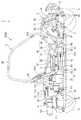
図1〜図3に示すように、本実施形態に係る車両1は、フロントフレーム部2と、センターフレーム部3と、リヤフレーム部4とを有して車体Bを構成する車体フレーム30を備える。フロントフレーム部2には、左右の前輪5を懸架する前輪用懸架装置(図示せず)が取り付けられ、フロントディファレンシャルギヤユニット81、フロントドライブシャフト82等の前輪駆動系や、前輪5を操舵する操舵部材(ステアリングシャフト6、このステアリングシャフト6の上端に取り付けたハンドル7を含む)等が支持されている。 As shown in FIGS. 1 to 3, the
センターフレーム部3には、車幅方向に並んで配置された運転席9および助手席10を構成する一対の乗員用シート11が取り付けられており、乗員の居住空間を構成する。助手席10の下部空間には、燃料タンク12が配設されると共に、運転席9と助手席10との間には、パワーユニットPとフロントディファレンシャルギヤユニット81とを連結するフロントプロペラシャフト83が配置されている。 A pair of
リヤフレーム部4には、左右の後輪15を懸架する後輪用懸架装置(図示せず)が取り付けられ、内燃機関13および変速機14を含むパワーユニットPに加え、リヤプロペラシャフト86、リヤディファレンシャルギヤユニット、リヤドライブシャフト85等の後輪駆動系等が支持されている。 A rear wheel suspension device (not shown) for suspending the left and right
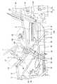
図3に示すように、リヤフレーム部4に支持されたパワーユニットPは、内燃機関13のクランクシャフト16が車体前後方向に向けて配置された縦置きレイアウトとされている。クランクシャフト16から動力が伝達される出力軸80は、略車体中心線CL上に配置され、その前端は、フロントプロペラシャフト83に連結され、後端はリヤプロペラシャフト86に連結されている。 As shown in FIG. 3, the power unit P supported by the rear frame portion 4 has a vertical layout in which the
リヤプロペラシャフト86は、略車体中心線CL上に配置されたリヤディファレンシャルギヤユニット84に接続されており、内燃機関13の駆動力は、リヤプロペラシャフト86、リヤディファレンシャルギヤユニット84、及び、リヤディファレンシャルギヤユニット84に接続されたリヤドライブシャフト85を介して左右の後輪15に伝達される。 The
フロントプロペラシャフト83には、その中間部にリダクションギヤ90が設けられており、フロントプロペラシャフト83は、リダクションギヤ90より後方に配置された第1プロペラシャフト87と、リダクションギヤ90より前方に配置された第2プロペラシャフト88とで構成される。リダクションギヤ90は、前輪5と後輪15を同一方向に回転させるため、第1プロペラシャフト87の回転方向を逆方向に変換して第2プロペラシャフト88に伝達する。これにより、内燃機関13の駆動力は、第1プロペラシャフト87、リダクションギヤ90、第2プロペラシャフト88、フロントディファレンシャルギヤユニット81、及び、フロントディファレンシャルギヤユニット81に接続されたフロントドライブシャフト82を介して左右の前輪5に伝達される。 The
図8に拡大して示すように、内燃機関13のシリンダヘッド18の後部には、スロットルバルブユニット19がインテークマニホールド20を通じて接続されており、シリンダヘッド18の前部には、後述する排気管120が接続されている。スロットルバルブユニット19の後部には、後述する第1及び第2エアクリーナ室111、112を備えたエアクリーナ110がコネクティングチューブ117を介して接続される。また、スロットルバルブユニット19には、燃料タンク12から延びる燃料配管21と、バッテリケース22やECU26等を備えたバッテリケース22から配索されたワイヤハーネス23が接続されている。 As shown in an enlarged view in FIG. 8, a
さらに、図2及び図4に示すように、内燃機関13には、フロントフレーム部2に配置されたラジエータ24が2本の水配管25によって接続されており、内燃機関13を冷却する冷却水は、水配管25を介してラジエータ24との間を循環する。 Further, as shown in FIGS. 2 and 4, the
なお、図1中、26はフロントカバー、27はインストルメントパネル、28は、中央のカバー部材28aと左右一対のカバー部材28bとからなるセンターコンソールカバーである。 In FIG. 1, 26 is a front cover, 27 is an instrument panel, and 28 is a center console cover comprising a
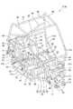
図4及び図5に示すように、車体フレーム30は、車体Bの左右下部に配置されて前後方向に延び、車体Bの前方から、フロントロアフレーム31と、センターロアフレーム32と、リヤロアフレーム33とを構成する一対のロアフレーム34を有する。 As shown in FIGS. 4 and 5, the
フロントフレーム部2では、フロントロアフレーム31の先端から、左右一対のフロントアッパフレーム70が上方に向かって延びた後、更に後方に延設されて前アッパクロスメンバ44に連結されて、車体Bの前部上方を覆っている。フロントロアフレーム31およびフロントアッパフレーム70は、コの字型フレーム71によって互いに結合されている。 In the front frame portion 2, a pair of left and right front
また、コの字型フレーム71とフロントアッパフレーム70の立上り部同士は、略L字型に形成されたフロントサスペンション支持パイプ72によって連結されている。フロントロアフレーム31およびフロントサスペンション支持パイプ72にそれぞれ2個ずつ固定されたブラケット63には、左右の前輪5を回転自在に懸架する前輪用懸架装置が揺動自在に配設されている。 The rising portions of the
一方、リヤフレーム部4では、左右一対のリヤアッパフレーム75がリヤロアフレーム33の後端から上方に延びた後、内燃機関13を含むパワーユニットPを覆うように屈曲して前方に延設され、センターロアフレーム32の乗員用シート11の後方から上方に延びる一対のセンター起立フレーム40に連結されている。リヤアッパフレーム75の水平部とリヤロアフレーム33とは、下方に向かうにつれて前方に傾斜するリヤ起立フレーム76によって上下方向に連結されている。また、リヤアッパフレーム75の垂直部とリヤ起立フレーム76とは、リヤサスペンション支持パイプ77によって連結されている。 On the other hand, in the rear frame portion 4, a pair of left and right rear
リヤロアフレーム33及びリヤサスペンション支持パイプ77に、それぞれ前後に2個ずつ固定された合計4個のブラケット78には、左右の後輪15を回転自在に懸架する後輪用懸架装置が揺動自在に配設されている。 A total of four
センターフレーム部3では、センターロアフレーム32の車幅方向外側に、センターロアフレーム32の前方に結合された結合パイプ66と、センター起立フレーム40の中間部に連結された結合パイプ67よって各ロアフレーム34とそれぞれ連結される左右一対のサイドフレーム51が前後方向に延びて配置されている。 In the center frame portion 3, each lower frame is connected to the outer side in the vehicle width direction of the center
サイドフレーム51は、前立上り部51aと、後立上り部51bと、前立上り部51aと後立上り部51bとを連結する水平部51cとによって下方に凸の略コの字型に形成されている。 The
略コの字型のサイドフレーム51は、サイドパイプ52によって前立上り部51aと後立上り部51bとが、前後方向に連結されている。一対のサイドフレーム51の前立上り部51aの端部同士は、前アッパクロスメンバ44によって車幅方向に連結されている。後立上り部51bの中間部と水平部51cの中間部とは、略L字型のシート支持用パイプ53によって連結されている。 In the substantially
一対のサイドフレーム51の前立上り部51aおよび後立上り部51bには、略コの字型に形成された一対のサイドアッパフレーム55が、上方に凸とされて連結されている。一対のサイドアッパフレーム55は、一対のセンター起立フレーム40の上端部が結合される第1アッパクロスメンバ54、2本のルーフクロスメンバ56、57、及び、第1アッパクロスメンバ54とも中間部で連結されるヘッドレスト用クロスメンバ58によって車幅方向に連結されている。 A pair of side
一対のシート支持用パイプ53には、ブラケットを介して第1シートクロスメンバ61が掛け渡されている。また、各サイドフレーム51の後立上り部51bには、1対のセンター起立フレーム40の中間部下方同士を車幅方向に連結する後クロスメンバ64とそれぞれ結合される一対の第2シートクロスメンバ62がブラケットを介して連結されている。これにより、第1及び第2シートクロスメンバ61,62と、これら第1及び第2シートクロスメンバ61、62とを前後方向に連結する連結フレーム65とはシートフレームを構成し、運転席9および助手席10のシートパイプ60(図9参照)はこれらシートフレーム上に取り付けられる。 A first
また、センターフレーム部3には、運転席9と助手席10との間を通り、ロアフレーム34の上方において略車体中心線CL上に前後方向に配置されたセンターパイプ35が設けられる。従って、センターフレーム部3は、車幅方向中央部にセンターパイプ35とロアフレーム34とが上下に配置され、サイド部にサイドパイプ52とサイドフレーム51とが上下に配置された構造となる。これにより、センターフレーム部3の剛性が向上すると共に、低床化、低重心化が可能となる。 Further, the center frame portion 3 is provided with a
図7にも拡大して示すように、センターパイプ35は、アッパセンターパイプ36と、ダウンセンターパイプ37と、起立センターパイプ38と、フロントセンターパイプ39と、を備え、各部材36,37,38,39は乗員用シート11より前方の結合点Jで交わり互いに結合されている。 7, the
アッパセンターパイプ36は、一対のセンター起立フレーム40同士を連結する後アッパクロスメンバ41の中央に一端が結合されて前方に延びる。ダウンセンターパイプ37は、センターロアフレーム32の乗員用シート11より下方に設けられた後ロアクロスメンバ42の中央に一端が結合されて前上方に延びる。 The
起立センターパイプ38は、センターロアフレーム32の乗員用シート11前方に設けられた前ロアクロスメンバ43の中央に一端が結合されて後上方に延びる。また、フロントセンターパイプ39は、結合点Jを基点として前方に向かって左右二股に形成された略V字型のパイプ部材であり、左右二股の端部は、フロントアッパフレーム70と前アッパクロスメンバ44との連結部近傍で前アッパクロスメンバ44に連結される。
なお、本実施形態では、一対のセンター起立フレーム40及び後アッパクロスメンバ41は、本発明の乗員シート後方の車体フレームを構成するフレームであり、センターロアフレーム32及び後ロアクロスメンバ42は、本発明のロアフレームを構成するフレームであり、フロントアッパフレーム70及び前アッパクロスメンバ44は、本発明の乗員シート前方の車体フレームを構成するフレームである。
The standing
In the present embodiment, the pair of
このように構成されるセンターパイプ35では、剛性が高くなった結合点J近傍の上方に、シフトレバー105が取り付けられ、また、アッパセンターパイプ36の中間部上方には、サイドブレーキレバー106が取り付けられている。なお、前アッパクロスメンバ44には、サブフレーム107を介して操舵部材であるステアリングシャフト6が取り付けられており、これらシフトレバー105、サイドブレーキレバー106、ステアリングシャフト6に加え、運転席9側に配置されたブレーキペダルやアクセルペダル等の足操作子91等から延びる各配線は、電気接続箱103に集約された後、一本のワイヤハーネス104として束ねられて運転席9の後方に設けられたバッテリケース22に接続される。 In the
また、図2、図3、及び図7に示すように、第1プロペラシャフト87は、センターパイプ35の下方で、センターパイプ35に沿って略車体中心線CL上に位置し、側面視において燃料タンク12と重なるように、換言すれば、燃料タンク12と車幅方向に並んで配置されている。リダクションギヤ90に接続された第2プロペラシャフト88は、第1プロペラシャフト87に対して車幅方向助手席10側にオフセットして配置されている。さらに、第2プロペラシャフト88は、フロントロアフレーム31の略車体中心線CL上に配設されたフロントディファレンシャルギヤユニット81に助手席10側で連結されている。 As shown in FIGS. 2, 3, and 7, the
このように、フロントプロペラシャフト83は、ほぼセンターパイプ35に沿って配置されているので、車両1の捩れ力がフロントプロペラシャフト83に作用し難い構造となっている。また、第2プロペラシャフト88が車幅方向助手席10側にオフセットして配置されているので、低床化されても乗員の居住空間を大きくとることができると共に、足操作子91のレイアウトの自由度が向上し、操作性のよい位置に配置することができる。 Thus, since the
また、リダクションギヤ90は、運転席9側に配置されたブレーキペダルやアクセルペダル等の足操作子91より後方、且つ一対の乗員用シート11より前方に位置し、ダウンセンターパイプ37と起立センターパイプ38との間に配置されている。 The
ラジエータ24と内燃機関13とを接続する2本の水配管25や電気接続箱103とバッテリケース22とを電気的に接続するワイヤハーネス104も、フロントプロペラシャフト83と同様に、起立センターパイプ38より前方では車幅方向助手席10側にオフセットして配置されている。 The two
このため、運転席9と助手席10との間に設けられたセンターコンソールカバー28は、その前部が助手席側にオフセットされた状態で、これらセンターパイプ35、フロントプロペラシャフト83、リダクションギヤ90、水配管25、ワイヤハーネス104、シフトレバー105、サイドブレーキレバー106を収容する。 For this reason, the
これにより、水配管25、およびワイヤハーネス104は、デッドスペースを利用してコンパクトに配置され、乗員の居住空間を大きくとることができると共に、足操作子91のレイアウトの自由度が向上し、操作性のよい位置に配置することができる。 As a result, the
また、車体フレーム30が左右対称形に配置され、且つ主な重量物であるフロントディファレンシャルギヤユニット81、リダクションギヤ90、内燃機関13、リヤディファレンシャルギヤユニット84等が略車体中心線CL上に配置されているので、左右の重量バランスが良好となり、車両1の安定性が増大する。 The
図8〜図10に示すように、吸気装置であるエアクリーナ110は、助手席10の後方、且つ内燃機関13の右側方に配置されており、第1エアクリーナ室111と第2エアクリーナ室112とを備える。 As shown in FIGS. 8 to 10, the
第1エアクリーナ室111には、助手席10の後方に配置され、開口を覆うカバー114を備えたシュノーケル113が、その車幅方向外側面に取り付けられたダクトを介して接続される。第1エアクリーナ室111と第2エアクリーナ室112は、リヤ起立フレーム76の一部を跨ぐようにして車幅方向に対向しており、接続チューブ116によって連通される。また、第2エアクリーナ室112は、コネクティングチューブ117によって内燃機関13に接続される。 A
これにより、第1エアクリーナ室111がリヤ起立フレーム76の車幅方向外側に配置され、第2エアクリーナ室112がリヤ起立フレーム76の車幅方向内側に配置される。また、空気中の塵埃を除去するエアクリーナエレメント115は、第1エアクリーナ室111内に収容されている。 As a result, the first air
このようなエアクリーナ110は、シュノーケル113から外部空気を導入し、第1エアクリーナ室111のエアクリーナエレメント115によって空気中の塵埃が除去され、接続チューブ116を通って第2エアクリーナ室112に導かれた後、コネクティングチューブ117から浄化された空気が内燃機関13へ供給される。 After
エアクリーナ110は、ロアフレーム34の車幅方向外側に配置された第1エアクリーナ室111と、車幅方向内側に配置された第2エアクリーナ室112とを備えるので、フレームで囲まれた狭い空間内に、大きな容量のエアクリーナ110をコンパクトに配置することができる。また、第1エアクリーナ室111がリヤ起立フレーム76の車幅方向外側に配置されているので、エアクリーナ110のメンテナンススペースが広くなり、メンテナンス作業を容易に行うことができ、整備性に優れる。
なお、第1エアクリーナ室111と第2エアクリーナ室112は、取付位置に応じて、リヤ起立フレーム76の他、ロアフレーム34やリヤアッパフレーム75の一部を跨ぐように配置される場合にも、上記効果を奏する。Since the
Note that the first air
また、図8及び図11に示すように、シリンダヘッド18の前部に接続された排気管120は、前方に向かって延びた後、Uターンして後方に向かって延び、さらに略90°で屈曲し、水平面に対して下方に傾斜しながら直線的に車体外方に向かって延びる。さらに、排気管120は、車幅方向で運転席9の後方領域に達した後、車体内方に屈曲して上方に傾斜しながら直線的に略車体中心線CL上に戻り、リヤフレーム部4の略車体中心線CL上に前後方向に向けて配設された消音器122に接続している。これにより、排気管120の最外方延出部121は、サイドフレーム51の後方延長線上より車幅方向内側、且つリヤアッパフレーム75より車幅方向外側まで延出している。 Further, as shown in FIGS. 8 and 11, the
従って、内燃機関13が乗員用シート11後方に配置されて、リヤフレーム部4のスペースが制約された、例えば低床化された車両1においても、排気管120の長さを必要長さだけ確保することができる。また、排気管120の直線部分が多いので、加工が容易であり、組立て工数を低減して制作費を抑制することができる。 Therefore, the
排気管120の最外方延出部121は、サイドフレーム51の後方延長線上より車幅方向内側、且つリヤアッパフレーム75より車幅方向外側まで延出している。これにより、排気管120の長さを確保しつつ、排気管120が保護される。 The outermost extending
また、排気管120は、リヤ起立フレーム76の前方で略車体中心線CL上に戻るので、リヤ起立フレーム76より後方に配設された後輪用懸架装置との干渉が確実に防止される。 Further, since the
以上説明したように、本実施形態に係る車両のフレーム構造によれば、センターパイプ35が、運転席9と助手席10との間を通り、車体フレーム30の略車体中心線CL上に前後方向に配置されるので、車体フレーム30の剛性を向上させることができる。 As described above, according to the vehicle frame structure according to the present embodiment, the
また、ロアフレーム34の車幅方向外側において前後方向に延びる左右一対のサイドフレーム51を備え、このサイドフレーム51の前後部をサイドパイプ52で連結すると共に、センターパイプ35が、ロアフレーム34の上方において略車体中心線CL上に前後方向に配置されるので、車体フレーム30のサイド部の剛性が、上下に配置されるサイドフレーム51とサイドパイプ52によって確保され、車体フレーム30のセンター部の剛性が、上下に配置されるロアフレーム34とセンターパイプ35によって確保される。これにより、車体フレーム30の剛性を維持したまま、乗員用シート高さ、および床高さを低くすることができ、低床化、低重心化が可能となる。 In addition, a pair of left and right side frames 51 extending in the front-rear direction on the outer side in the vehicle width direction of the
さらに、センターパイプ35は、アッパセンターパイプ36、ダウンセンターパイプ37、起立センターパイプ38、およびフロントセンターパイプ39からなり、これらの各部材36,37,38,39が乗員用シート前方の結合点Jで交わり結合されているので、このセンターパイプ構造によって車体の剛性を向上させることができる。 Further, the
加えて、車体Bの前部上方を覆うようにフロントロアフレーム31の先端から延びる左右一対のフロントアッパフレーム70を備え、左右二股に形成されたフロントセンターパイプ39が、フロントアッパフレーム70と前アッパクロスメンバ44の左右連結部近傍に連結されているので、車体Bの剛性をより向上させることができる。また、前アッパクロスメンバ44にかかる折れ曲がり力を低減することができる。 In addition, a pair of left and right front
また、前輪駆動系に内燃機関13の駆動力を伝達するフロントプロペラシャフト83が、略センターパイプ35に沿って配置されているので、車体Bの捩れ力がフロントプロペラシャフト83に作用し難くすることができる。また、センターパイプ35下方のデッドスペースを利用してフロントプロペラシャフト83を配置することができ、コンパクトなレイアウトが可能となって乗員の居住空間を大きくとることができる。 In addition, since the
さらに、フロントプロペラシャフト83の回転方向を逆方向に変換するリダクションギヤ90が、足操作子91より後方且つ乗員用シート19より前方に位置し、ダウンセンターパイプ37と起立センターパイプ38との間に配置されているので、リダクションギヤ90を車体剛性が高いデッドスペースに配置することができ、リダクションギヤ90を保護すると共に、コンパクトなレイアウトが可能となって乗員の居住空間を大きくとることができる。 Further, a
また、センターパイプ35が、乗員の居住空間を備えるセンターフレーム部に設けられるので、センターフレーム部3の剛性を向上させることができる。 Moreover, since the
また、フロントフレーム部2にラジエータ24が配置され、リヤフレーム部4に内燃機関13が配置される構成において、このラジエータ24と内燃機関13とを繋ぐ水配管25が、起立センターパイプ38より前方において該起立センターパイプ38より助手席側を通るようにして、略センターパイプ35に沿って配置されている。これにより、水配管25を車体剛性が高いデッドスペースに配置することができ、水配管25を保護すると共に、コンパクトなレイアウトが可能となって乗員の居住空間を大きくとることができる。 Further, in the configuration in which the
また、シフトレバー105は、センターパイプ35を構成する各部材36,37,38,39の結合点Jの近傍に配置されるので、シフトレバー105は、別途専用の支持ブラケットを設けることなく、車体剛性の高く、且つ、運転者の操作性の良い位置に設けることができる。 In addition, since the
さらに、サイドブレーキレバー106は、アッパセンターパイプ36上に配置されるので、サイドブレーキレバー106も、別途専用の支持ブラケットを設けることなく、運転者の操作性の良い位置に設けることができる。 Further, since the
また、運転席9と助手席10との間に設けられたセンターコンソールカバー28は、センターパイプ35、フロントプロペラシャフト83、リダクションギヤ90、水配管25、ワイヤハーネス104、シフトレバー105、サイドブレーキレバー106を収容するので、これら部材を車体センターに集約することができると共に、センターコンソールカバー28によって覆うことで外観が良くなり、乗員の居住空間を広く取ることができる。 A
尚、本発明は、前述した実施形態に限定されるものではなく、適宜、変形、改良等が可能である。例えば、本発明においては、MUV(マルチ・ユーティリティ・ビークル)に適用したものとして説明したが、これに限定されるものではなく、4輪以上の車輪を有する任意の形式の車両にも同様に適用することができる。 In addition, this invention is not limited to embodiment mentioned above, A deformation | transformation, improvement, etc. are possible suitably. For example, although the present invention has been described as applied to an MUV (multi-utility vehicle), the present invention is not limited to this, and is similarly applied to any type of vehicle having four or more wheels. can do.
1 車両
2 フロントフレーム部
3 センターフレーム部
4 リヤフレーム部
9 運転席
10 助手席
11 乗員用シート
13 内燃機関
30 車体フレーム
31 フロントロアフレーム
32 センターロアフレーム
33 リヤロアフレーム
34 ロアフレーム
35 センターパイプ
36 アッパセンターパイプ
37 ダウンセンターパイプ
38 起立センターパイプ
39 フロントセンターパイプ
40 センター起立フレーム
41 後アッパクロスメンバ
42 後ロアクロスメンバ
43 前ロアクロスメンバ
44 前アッパクロスメンバ
51 サイドフレーム
52 サイドパイプ
70 フロントアッパフレーム
81 フロントディファレンシャルギヤユニット(前輪駆動系)
82 フロントドライブシャフト(前輪駆動系)
83 フロントプロペラシャフト
84 リヤディファレンシャルギヤユニット(後輪駆動系)
85 リヤドライブシャフト(後輪駆動系)
86 リヤプロペラシャフト
87 第1プロペラシャフト
88 第2プロペラシャフト
90 リダクションギヤ
91 足操作子
B 車体
CL 車体中心線
J 結合点DESCRIPTION OF
82 Front drive shaft (front wheel drive system)
83
85 Rear drive shaft (rear wheel drive system)
86
Claims (6)
Translated fromJapanese該車体フレーム(30)に車幅方向に並んで配置され、運転席(9)および助手席(10)を構成する一対の乗員用シート(11)と、を備える車両のフレーム構造であって、
前記運転席(9)と前記助手席(10)との間を通り、前記車体フレーム(30)の略車体中心線上に前後方向に配置されたセンターパイプ(35)と、
前記車体の左右下部に配置されて前後方向に延びるロアフレーム(34)と、
前記ロアフレーム(34)の車幅方向外側において前後方向に延びる左右一対のサイドフレーム(51)と、
前記各サイドフレーム(51)を前後方向に連結する一対のサイドパイプ(52)と、
を備え、
前記センターパイプ(35)は、前記ロアフレーム(34)の上方において、略車体中心線上に前後方向に配置されることを特徴とする車両のフレーム構造。A body frame(30) ;
A vehicle frame structure comprising a pair of passenger seats(11) arranged side by side in the vehicle width direction on the vehicle body frame(30) and constituting a driver seat(9) and a passenger seat(10) ,
A center pipe(35) that passes between the driver seat(9) and the passenger seat(10) and is disposed in a front-rear direction on a substantially vehicle body center line of the vehicle body frame(30);
A lower frame (34) disposed in the lower left and right of the vehicle body and extending in the front-rear direction;
A pair of left and right side frames (51) extending in the front-rear direction on the outer side in the vehicle width direction of the lower frame (34);
A pair of side pipes (52) connecting the side frames (51) in the front-rear direction;
With
The center pipe (35) is disposed above and below thelower frame (34) in a front-rear direction substantially on a vehicle body center line .
前記ロアフレーム(34)を構成するフレームを介し前記乗員用シート(11)間の下方から前上方に延びるダウンセンターパイプ(37)と、
前記ロアフレーム(34)の前記乗員用シート(11)前方から後上方に延びる起立センターパイプ(38)と、
前記乗員用シート(11)前方の車体フレーム(30)を構成するフレームから後下方に延びるフロントセンターパイプ(39)と、からなり、
前記アッパセンターパイプ(36)、前記ダウンセンターパイプ(37)、前記起立センターパイプ(38)、および前記フロントセンターパイプ(39)は、前記乗員用シート(11)前方の結合点(J)で交わり結合されることを特徴とする請求項1に記載の車両のフレーム構造。The center pipe(35) includes an upper center pipe(36) extending forward of the vehicle body from a frame constituting the vehicle body frame(30) behind the occupant seat(11) ,
A down center pipe(37) extending from the lower part between the occupant seats(11) to the front upper part through a frame constituting the lower frame(34) ;
A standing center pipe(38) extending from the front to the rear of the passenger seat(11) of the lower frame(34) ;
A front center pipe(39) extending rearward and downward from a frame constituting the vehicle body frame(30) in front of the occupant seat(11) ,
The upper center pipe(36) , the down center pipe(37) , the standing center pipe(38) , and the front center pipe(39) are cross-coupled at a coupling point(J) in front of the occupant seat(11). The vehicle frame structure according to claim1 .
前記フロントセンターパイプ(39)は、前記結合点(J)を基点として前方に向かって左右二股に形成され、前記フロントアッパフレーム(70)と前記前アッパクロスメンバ(44)の左右連結部近傍に連結されることを特徴とする請求項1または請求項2に記載の車両のフレーム構造。A pair of left and right front upper frames(70) extending upward from the front end of the lower frame(34) and extending rearward and connected to thefront upper cross member(44) to cover the upper front part of the vehicle body.)
The front center pipe(39) is bifurcated forward from the connection point(J), and is connected to the vicinity of the left and right connecting portions of the front upper frame(70) and the front upper cross member(44). The vehicle frame structure according to claim 1or2 , wherein the vehicle frame structure is provided.
前記プロペラシャフト(87,88)の中間部に連結されて、前記プロペラシャフト(87,88)の回転方向を逆方向に変換するリダクションギヤ(90)と、
を更に備え、
前記リダクションギヤ(90)は、前記足操作子(91)より後方且つ前記乗員用シート(11)より前方で、前記ダウンセンターパイプ(37)と前記起立センターパイプ(38)との間に配置されることを特徴とする請求項4に記載の車両のフレーム構造。A foot operator(91) operable by a passenger's foot;
Wherein is connected to an intermediate portion of the propeller shaft(87, 88), and reduction gear for converting the rotation direction of the propeller shaft(87, 88) in the opposite direction(90),
Further comprising
The reduction gear(90) is disposed between the down center pipe(37) and the standing center pipe(38) behind the foot operator(91) and in front of the occupant seat(11). The vehicle frame structure according to claim4 .
前記センターパイプ(35)は、前記センターフレーム部(3)に設けられることを特徴とする請求項1から請求項5のいずれかに記載の車両のフレーム構造。The vehicle body frame(30) includes a front frame portion(2) that supports a front wheel drive system, a center frame portion(3) that includes a passenger's living space, and a rear frame portion(4) that supports a rear wheel drive system. Have
The vehicle frame structure according to any one of claims 1 to5 , wherein the center pipe(35) is provided in the center frame portion(3) .
Priority Applications (3)
| Application Number | Priority Date | Filing Date | Title |
|---|---|---|---|
| JP2008253176AJP5093506B2 (en) | 2008-09-30 | 2008-09-30 | Vehicle frame structure |
| CA2673393ACA2673393C (en) | 2008-09-30 | 2009-07-21 | Frame structure for vehicle |
| US12/558,575US8100434B2 (en) | 2008-09-30 | 2009-09-14 | Frame structure for vehicle and vehicle |
Applications Claiming Priority (1)
| Application Number | Priority Date | Filing Date | Title |
|---|---|---|---|
| JP2008253176AJP5093506B2 (en) | 2008-09-30 | 2008-09-30 | Vehicle frame structure |
Publications (2)
| Publication Number | Publication Date |
|---|---|
| JP2010083274A JP2010083274A (en) | 2010-04-15 |
| JP5093506B2true JP5093506B2 (en) | 2012-12-12 |
Family
ID=42056596
Family Applications (1)
| Application Number | Title | Priority Date | Filing Date |
|---|---|---|---|
| JP2008253176AExpired - Fee RelatedJP5093506B2 (en) | 2008-09-30 | 2008-09-30 | Vehicle frame structure |
Country Status (3)
| Country | Link |
|---|---|
| US (1) | US8100434B2 (en) |
| JP (1) | JP5093506B2 (en) |
| CA (1) | CA2673393C (en) |
Families Citing this family (22)
| Publication number | Priority date | Publication date | Assignee | Title |
|---|---|---|---|---|
| US8827028B2 (en)* | 2006-07-28 | 2014-09-09 | Polaris Industries Inc. | Side-by-side ATV |
| US7819220B2 (en)* | 2006-07-28 | 2010-10-26 | Polaris Industries Inc. | Side-by-side ATV |
| JP5548409B2 (en)* | 2009-08-25 | 2014-07-16 | 本田技研工業株式会社 | Vehicle frame structure |
| US8944449B2 (en) | 2010-04-06 | 2015-02-03 | Polaris Industries Inc. | Side-by-side vehicle |
| US8746719B2 (en) | 2010-08-03 | 2014-06-10 | Polaris Industries Inc. | Side-by-side vehicle |
| US8613335B2 (en) | 2010-08-03 | 2013-12-24 | Polaris Industries Inc. | Side-by-side vehicle |
| US9650078B2 (en) | 2011-02-11 | 2017-05-16 | Polaris Industries Inc. | Side-by-side all terrain vehicle |
| CN202147725U (en)* | 2011-06-23 | 2012-02-22 | 浙江吉利汽车研究院有限公司 | Car frame structure |
| US8485303B2 (en)* | 2011-10-07 | 2013-07-16 | Kawasaki Jukogyo Kabushiki Kaisha | Utility vehicle |
| HK1210992A1 (en)* | 2012-09-20 | 2016-05-13 | 北极星工业有限公司 | Utiliy vehicle |
| US9440671B2 (en) | 2012-09-20 | 2016-09-13 | Polaris Industries Inc. | Vehicle |
| US9789909B2 (en) | 2013-03-15 | 2017-10-17 | Polaris Industries Inc. | Utility vehicle |
| MX2017014403A (en) | 2015-05-15 | 2018-04-11 | Polaris Inc | UTILITY VEHICLE. |
| USD787985S1 (en) | 2015-06-24 | 2017-05-30 | Polaris Industries Inc. | All-terrain vehicle |
| US9649928B2 (en) | 2015-06-25 | 2017-05-16 | Polaris Industries Inc. | All-terrain vehicle |
| US10633028B2 (en)* | 2017-11-22 | 2020-04-28 | Honda Motor Co., Ltd. | Autonomous all-terrain vehicle frame structure |
| US10946736B2 (en) | 2018-06-05 | 2021-03-16 | Polaris Industries Inc. | All-terrain vehicle |
| JP7322743B2 (en)* | 2020-02-17 | 2023-08-08 | トヨタ自動車株式会社 | vehicle frame structure |
| US12187127B2 (en) | 2020-05-15 | 2025-01-07 | Polaris Industries Inc. | Off-road vehicle |
| JP7563269B2 (en)* | 2021-03-26 | 2024-10-08 | マツダ株式会社 | Electric vehicle undercarriage |
| MX2023006716A (en) | 2022-06-13 | 2023-12-14 | Polaris Inc | POWER TRAIN FOR UTILITY VEHICLE. |
| USD1067123S1 (en) | 2023-01-20 | 2025-03-18 | Polaris Industries Inc. | Off-road vehicle |
Family Cites Families (10)
| Publication number | Priority date | Publication date | Assignee | Title |
|---|---|---|---|---|
| JPS60148706A (en)* | 1984-01-17 | 1985-08-06 | カ−チス・エイ・ダイア− | Automobile |
| JPH01309823A (en)* | 1988-06-06 | 1989-12-14 | Iseki & Co Ltd | Front axle device of four-wheel drive tractor |
| JP3467003B2 (en)* | 2000-08-08 | 2003-11-17 | 有限会社スイート | Undercarriage structure for lightweight sports car |
| US7506712B2 (en)* | 2003-04-02 | 2009-03-24 | Yamaha Hatsudoki Kabushiki Kaisha | Off road vehicle with air intake system |
| US7287619B2 (en)* | 2003-04-02 | 2007-10-30 | Yamaha Hatsudoki Kabushiki Kaisha | Air intake system for off-road vehicle |
| JP4478542B2 (en) | 2004-09-30 | 2010-06-09 | 本田技研工業株式会社 | Vehicle body frame structure |
| US7537499B2 (en)* | 2004-12-30 | 2009-05-26 | American Off-Road Technologies, Llc | Reduced-size vehicle with compartments providing buoyancy |
| US7658258B2 (en)* | 2005-06-10 | 2010-02-09 | Thorpe North & Western LLP | All terrain vehicle swept A-frame suspension and central support truss |
| JP4606290B2 (en)* | 2005-09-26 | 2011-01-05 | 本田技研工業株式会社 | Vehicle suspension structure |
| US7819220B2 (en)* | 2006-07-28 | 2010-10-26 | Polaris Industries Inc. | Side-by-side ATV |
- 2008
- 2008-09-30JPJP2008253176Apatent/JP5093506B2/ennot_activeExpired - Fee Related
- 2009
- 2009-07-21CACA2673393Apatent/CA2673393C/ennot_activeExpired - Fee Related
- 2009-09-14USUS12/558,575patent/US8100434B2/ennot_activeExpired - Fee Related
Also Published As
| Publication number | Publication date |
|---|---|
| US20100078926A1 (en) | 2010-04-01 |
| US8100434B2 (en) | 2012-01-24 |
| JP2010083274A (en) | 2010-04-15 |
| CA2673393C (en) | 2011-11-22 |
| CA2673393A1 (en) | 2010-03-30 |
Similar Documents
| Publication | Publication Date | Title |
|---|---|---|
| JP5093506B2 (en) | Vehicle frame structure | |
| JP4965537B2 (en) | Body structure | |
| JP5317617B2 (en) | Vehicle exhaust pipe structure | |
| JP5206957B2 (en) | Vehicle intake structure | |
| JP2008114617A (en) | Vehicle electrical component arrangement structure | |
| JP6294200B2 (en) | Drive wheel independent suspension system | |
| JP5129632B2 (en) | Harness holding structure for saddle-ride type vehicles | |
| JP7454104B2 (en) | saddle type vehicle | |
| CN102030063A (en) | Automotive two-wheel vehicle | |
| US9555850B2 (en) | Saddle-type vehicle | |
| JP2011025865A (en) | Vehicle transmission member routing structure | |
| JP4467054B2 (en) | Vehicle body frame structure | |
| JP2003212147A (en) | Frame for riding tractor | |
| JP7663621B2 (en) | Electric vehicles | |
| JP4593446B2 (en) | Vehicle front structure | |
| JP5807533B2 (en) | Vehicle floor structure | |
| JP6670788B2 (en) | Body structure of saddle type vehicle | |
| JPWO2012057159A1 (en) | Motorcycle | |
| US11643163B2 (en) | Saddle-type vehicle | |
| JP5470732B2 (en) | Vehicle powertrain arrangement structure | |
| WO2025074647A1 (en) | Leaning vehicle | |
| WO2025074649A1 (en) | Leaning vehicle | |
| JP2011031747A (en) | Vehicle rear structure | |
| JP2023047999A (en) | saddle-riding vehicle | |
| JPH06144019A (en) | Driving system arranging structure for vehicle |
Legal Events
| Date | Code | Title | Description |
|---|---|---|---|
| A621 | Written request for application examination | Free format text:JAPANESE INTERMEDIATE CODE: A621 Effective date:20101126 | |
| A977 | Report on retrieval | Free format text:JAPANESE INTERMEDIATE CODE: A971007 Effective date:20120528 | |
| A131 | Notification of reasons for refusal | Free format text:JAPANESE INTERMEDIATE CODE: A131 Effective date:20120605 | |
| A521 | Request for written amendment filed | Free format text:JAPANESE INTERMEDIATE CODE: A523 Effective date:20120801 | |
| RD03 | Notification of appointment of power of attorney | Free format text:JAPANESE INTERMEDIATE CODE: A7423 Effective date:20120801 | |
| RD04 | Notification of resignation of power of attorney | Free format text:JAPANESE INTERMEDIATE CODE: A7424 Effective date:20120802 | |
| TRDD | Decision of grant or rejection written | ||
| A01 | Written decision to grant a patent or to grant a registration (utility model) | Free format text:JAPANESE INTERMEDIATE CODE: A01 Effective date:20120821 | |
| A01 | Written decision to grant a patent or to grant a registration (utility model) | Free format text:JAPANESE INTERMEDIATE CODE: A01 | |
| A61 | First payment of annual fees (during grant procedure) | Free format text:JAPANESE INTERMEDIATE CODE: A61 Effective date:20120904 | |
| R150 | Certificate of patent or registration of utility model | Ref document number:5093506 Country of ref document:JP Free format text:JAPANESE INTERMEDIATE CODE: R150 Free format text:JAPANESE INTERMEDIATE CODE: R150 | |
| FPAY | Renewal fee payment (event date is renewal date of database) | Free format text:PAYMENT UNTIL: 20150928 Year of fee payment:3 | |
| LAPS | Cancellation because of no payment of annual fees |