JP5093190B2 - Image processing device - Google Patents
Image processing deviceDownload PDFInfo
- Publication number
- JP5093190B2 JP5093190B2JP2009136216AJP2009136216AJP5093190B2JP 5093190 B2JP5093190 B2JP 5093190B2JP 2009136216 AJP2009136216 AJP 2009136216AJP 2009136216 AJP2009136216 AJP 2009136216AJP 5093190 B2JP5093190 B2JP 5093190B2
- Authority
- JP
- Japan
- Prior art keywords
- screen
- display
- unit
- screens
- image processing
- Prior art date
- Legal status (The legal status is an assumption and is not a legal conclusion. Google has not performed a legal analysis and makes no representation as to the accuracy of the status listed.)
- Expired - Fee Related
Links
- 230000002776aggregationEffects0.000claimsdescription8
- 238000004220aggregationMethods0.000claimsdescription8
- 238000000034methodMethods0.000description33
- 230000008569processEffects0.000description26
- 230000006870functionEffects0.000description20
- 239000004973liquid crystal related substanceSubstances0.000description18
- 238000010586diagramMethods0.000description17
- 230000004888barrier functionEffects0.000description10
- 230000008859changeEffects0.000description4
- 230000002093peripheral effectEffects0.000description3
- 238000004364calculation methodMethods0.000description2
- 230000004044responseEffects0.000description2
- 101100345318Arabidopsis thaliana MFP2 geneProteins0.000description1
- 125000002066L-histidyl groupChemical group[H]N1C([H])=NC(C([H])([H])[C@](C(=O)[*])([H])N([H])[H])=C1[H]0.000description1
- 230000005540biological transmissionEffects0.000description1
- 230000000903blocking effectEffects0.000description1
- 238000012790confirmationMethods0.000description1
- 238000013500data storageMethods0.000description1
- 230000000694effectsEffects0.000description1
- 238000003825pressingMethods0.000description1
- 238000004904shorteningMethods0.000description1
- 238000003860storageMethods0.000description1
Images


Classifications
- G—PHYSICS
- G03—PHOTOGRAPHY; CINEMATOGRAPHY; ANALOGOUS TECHNIQUES USING WAVES OTHER THAN OPTICAL WAVES; ELECTROGRAPHY; HOLOGRAPHY
- G03G—ELECTROGRAPHY; ELECTROPHOTOGRAPHY; MAGNETOGRAPHY
- G03G15/00—Apparatus for electrographic processes using a charge pattern
- G03G15/50—Machine control of apparatus for electrographic processes using a charge pattern, e.g. regulating differents parts of the machine, multimode copiers, microprocessor control
- G03G15/5016—User-machine interface; Display panels; Control console
- G03G15/502—User-machine interface; Display panels; Control console relating to the structure of the control menu, e.g. pop-up menus, help screens
Landscapes
- Engineering & Computer Science (AREA)
- Human Computer Interaction (AREA)
- Microelectronics & Electronic Packaging (AREA)
- Physics & Mathematics (AREA)
- General Physics & Mathematics (AREA)
- User Interface Of Digital Computer (AREA)
- Facsimiles In General (AREA)
- Controls And Circuits For Display Device (AREA)
- Control Or Security For Electrophotography (AREA)
- Digital Computer Display Output (AREA)
- Control Of Indicators Other Than Cathode Ray Tubes (AREA)
Description
Translated fromJapanese本発明は、画像処理装置に関し、特に、階層構造を有する複数の画面から構成されたユーザインタフェース画面を有する画像処理装置に関する。 The present invention relates to an image processing device, and more particularly to an image processing device having a user interface screen composed of a plurality of screens having a hierarchical structure.
近年、画像処理装置の機能は多機能化する傾向にあり、例えば、そのような画像処理装置の一例であるデジタル複合機(MultiFunction Peripheral、MFP)は、一台でコピー機能、スキャナ機能、プリンタ機能、ファクシミリ機能、メール送受信機能等を集約的に併せ持つ装置である。多くのMFPにおいては、そのユーザインタフェース装置には、タッチパネルと一体的に構成された液晶表示装置(LCDタッチパネル)が利用される。MFPのLCDタッチパネル上には、自機の現在の状態や、各種機能設定のためのキー群が表示され、操作者は、該パネルに表示されたキーに触れることでMFPに対し各種の入力を行う。しかしながら、LCDタッチパネルの表示面の面積は限定的であり、MFPを操作するのに必要なキーの全てを同時に表示することはできない。そのため、MFPのユーザインタフェース装置は、複数の画面を有し、適宜、表示する画面を切り換える。操作者は、LCDタッチパネルに触れ、例えば、次々と表示されるメニューから所望の選択肢を選択して、MFPの様々な機能を使用する。 In recent years, the functions of image processing apparatuses tend to be multifunctional. For example, a digital multifunction peripheral (MFP) which is an example of such an image processing apparatus has a copy function, a scanner function, and a printer function. It is an apparatus that collectively has a facsimile function, a mail transmission / reception function, and the like. In many MFPs, a liquid crystal display device (LCD touch panel) integrated with a touch panel is used as the user interface device. On the LCD touch panel of the MFP, the current state of the machine and a group of keys for setting various functions are displayed. The operator touches the keys displayed on the panel to input various inputs to the MFP. Do. However, the area of the display surface of the LCD touch panel is limited, and all the keys necessary for operating the MFP cannot be displayed simultaneously. Therefore, the user interface device of the MFP has a plurality of screens, and switches display screens as appropriate. The operator touches the LCD touch panel and selects a desired option from menus displayed one after another, for example, and uses various functions of the MFP.
複数の画面を構成する手法として、画面の階層化という手法が知られている。この場合、画面の階層が深くなるに従ってより詳細な設定が可能となるように、階層構造が構成される。MFPでは、各動作モード(コピー、スキャン、ファクシミリ、等)について基本画面と称される画面が用意される。この場合各動作モードについての基本画面は、上記した階層構造における最上位階層に位置付けされる。コピーモードを例にすれば、操作者は、コピーモード基本画面(図6参照。)から、各機能の詳細設定を開始する。コピーモード基本画面において「用紙」にタッチすると、画面は、用紙選択画面に切り替わる(図7参照。)。さらに用紙選択画面では、「選択トレーの設定変更」にタッチすることで、図9の画面に切り替わり、各給紙カセットに入っている用紙の種類を変更することができる。
このように、動作モードについての設定を完了させるまでに、操作者は、多くの階層を往来する必要があり、操作に時間を要する。また、動作モードについての設定内容の確認なども、専用のキーを選択しないと、詳細な情報表示ができないことも多い。As a technique for configuring a plurality of screens, a technique called screen hierarchization is known. In this case, the hierarchical structure is configured so that more detailed settings can be made as the screen hierarchy becomes deeper. In the MFP, a screen called a basic screen is prepared for each operation mode (copy, scan, facsimile, etc.). In this case, the basic screen for each operation mode is positioned at the highest hierarchy in the hierarchical structure described above. Taking the copy mode as an example, the operator starts detailed setting of each function from the copy mode basic screen (see FIG. 6). When “paper” is touched on the copy mode basic screen, the screen is switched to a paper selection screen (see FIG. 7). Further, on the paper selection screen, by touching “Change setting of selected tray”, the screen is switched to the screen of FIG. 9 and the type of paper in each paper feed cassette can be changed.
As described above, the operator needs to go through many levels before completing the setting of the operation mode, and the operation takes time. In addition, when confirming the setting contents of the operation mode, detailed information display is often impossible unless a dedicated key is selected.
従来、LCDタッチパネルを利用したユーザインタフェース装置における画面表示の手法に関して様々な提案がなされている。 Conventionally, various proposals have been made regarding screen display methods in a user interface device using an LCD touch panel.
特許文献1は、画像形成装置を開示する。当該文献の画像形成装置は、複数の画面に切り替えることができる表示画面を備えている。そして、当該装置においては、操作者が使用する頻度の高い機能を学習し、使用頻度の高い機能は第1画面に表示され、使用頻度の高くない機能は第2画面以降に表示される。このように、当該画像形成装置は、1つの表示画面を複数の領域に分割して、操作者がよく使う機能を表示する領域を確保することにより、操作者の利便性の向上を図る。
特許文献2は、MFP等の画像処理装置においてユーザインタフェース装置として利用可能な表示装置を開示する。当該文献の表示装置は、所定のキー操作があると、既に表示されている内容を画面内の別の位置に移動させ、当該移動により生じた空いたスペースに第2の表示部を表示する。第2の表示部には、上記所定のキー操作に対応して新たなキー等が表示される。このように、当該表示装置は、上記所定のキー操作直前の時点において表示していた内容を表示しつつ、上記所定のキー操作に対応した新たな内容を表示することで、操作者の利便性の向上を図る。
特許文献3は、画像記録装置において利用可能なタッチパネル入力/表示装置を開示する。当該文献の入力/表示装置は、画像記録装置の有する機能に含まれる任意の複数の機能に対する操作に対応した、複数のキーについて同時的に表示画面に表示するように設定可能である。このようにタッチパネル入力/表示装置を構成することにより、FAX、コピー、スキャン、といった複数の機能について、同一の画面上に同時的に表示し操作者が操作可能になる。 Patent Document 3 discloses a touch panel input / display device that can be used in an image recording apparatus. The input / display device of this document can be set so that a plurality of keys corresponding to operations for any of a plurality of functions included in the functions of the image recording apparatus are displayed on the display screen simultaneously. By configuring the touch panel input / display device in this way, a plurality of functions such as FAX, copy, and scan can be simultaneously displayed on the same screen and operated by the operator.
特許文献4は、画像処理システムを開示する。当該文献の画像処理システムは、画像処理に関する情報を表示する表示部が設けられた画像処理ユニットを複数個備える。そして、各画像処理ユニットにおける表示部においては、別の画像処理ユニットの状態についての情報を当該別の画像処理ユニットから受け取り、別の画像処理ユニットの状態に基づいて自機の表示部の表示を切り替える。このように構成される画像処理システムでは、画像処理ユニットの表示部の表示が別の画像処理ユニットの動作状態に連動して切り替わるため、操作者が複数の画像処理ユニットを協働的に利用するような場合における、操作の利便性の向上が期待される。 Patent Document 4 discloses an image processing system. The image processing system of the document includes a plurality of image processing units provided with a display unit that displays information related to image processing. The display unit in each image processing unit receives information about the state of another image processing unit from the other image processing unit, and displays the display unit of its own device based on the state of the other image processing unit. Switch. In the image processing system configured as described above, since the display on the display unit of the image processing unit is switched in conjunction with the operation state of another image processing unit, the operator cooperates with a plurality of image processing units. In such a case, the convenience of operation is expected to be improved.
このように、ユーザインタフェースとして複数の画面を備えた装置、システムに関する提案は多い。 As described above, there are many proposals regarding an apparatus and a system having a plurality of screens as a user interface.
しかしながら、階層化構造を有する複数の画面で構成された画面表示方式を採った場合、操作者は所望の操作(設定等)を行うために画面切替のための操作を何度も行わなければ、目的の画面を表示することができない。そのため、操作者は、操作手順を記憶しておかなければならない。
また、操作者は、誤った設定を画像処理装置に対して行ってしまうこともしばしばである。このような誤設定は、深い(下位)階層にある画面においてある操作を行っているときに別の設定項目に現在の設定値を参照することができないことに起因する場合がある。
また、現在表示中の画面の階層構造における位置が解らなくなり、別の画面に切り替えるために多くの時間を要することもしばしばである。However, when a screen display method composed of a plurality of screens having a hierarchical structure is adopted, the operator does not perform an operation for switching the screen many times in order to perform a desired operation (setting, etc.) The target screen cannot be displayed. Therefore, the operator must memorize | store the operation procedure.
In addition, the operator often performs wrong settings on the image processing apparatus. Such an erroneous setting may be caused by the fact that the current setting value cannot be referred to another setting item when a certain operation is performed on a screen in a deep (lower) hierarchy.
In addition, the position in the hierarchical structure of the currently displayed screen is not understood, and it often takes a lot of time to switch to another screen.
上記従来技術における課題を解決するため、本発明は、階層化画面表示方式を採るユーザインタフェースを備えた画像処理装置を提供する。本発明にあっては、同時的に相異なる階層深度の画面を表示することができる画像処理装置を提供することにより、操作者の操作の利便性を向上させ、上記従来技術における課題の解決を図る。 In order to solve the above-described problems in the prior art, the present invention provides an image processing apparatus provided with a user interface that employs a hierarchical screen display method. In the present invention, by providing an image processing device capable of simultaneously displaying screens having different hierarchical depths, the convenience of the operation of the operator is improved, and the above-described problems in the prior art are solved. Plan.
本発明は、その一態様において、階層構造を具備する複数の画面で構成されるユーザインタフェース画面を有する画像処理装置であって、同一画面上に、互いに視方向が異なるよう表示される第1画面および第2画面を含む少なくとも2つの画面を同時的に表示するユーザインタフェース表示部と、設定操作の入力を受けるユーザインタフェース操作部と、第1画面および第2画面の内容を決定する表示画面決定部とを有し、表示画面決定部は、自機に設定されている内容に基づいて、第1画面を決定し、決定した第1画面から選択可能なひとつ下位の階層にある複数の画面のうちの1つを第2画面に自動的に決定し、当該決定に基づいて、ユーザインタフェース表示部に第1画面および第2画面を表示させる、画像処理装置である。
In one aspect, the present invention is an image processing apparatus having a user interface screen composed of a plurality of screens having a hierarchical structure, wherein the first screen is displayed on the same screen so as to have different viewing directions. A user interface display unit that simultaneously displays at least two screens including the second screen, a user interface operation unit that receives an input of a setting operation, and a display screen determination unit that determines the contents of the first screen and the second screen The display screen determination unit determines the first screen based on the contents set in the own device, and among the plurality of screens in the one lower hierarchy selectable from the determined first screen Isautomatically determined as the second screen, and the first screen and the second screen are displayed on the user interface display unit based on the determination.
本発明の一態様においては、ユーザインタフェース操作部を介して、第1画面から選択可能なひとつ下位の階層の画面を表示する操作の入力を受けた場合には、表示画面決定部は、表示する操作の入力にかかるひとつ下位の階層の画面を第1画面に決定し、決定した第1画面から選択可能なひとつ下位の階層の画面を第2画面に決定することが好ましい。In one aspect of the present invention, the display screen determining unit displays when an input of an operation for displaying a screen that is one level lower than thatselectable from the first screen isreceived via the user interface operation unit. It is preferable that the screen of the one lower layer related to the input of the operation is determined as the first screen, and the screen of the one lower layer that can beselected from the determined first screen is determined as the second screen.
本発明の一態様においては、さらに、設定操作の入力を記録して各設定操作の入力にかかる頻度を集計する操作頻度集計部を有し、表示画面決定部は、操作頻度集計部がする頻度の集計に基づいて、前記ひとつ下位の階層にある複数複数の画面のうちで頻度が高い画面を第2画面に決定することが好ましい。In one aspect of the present invention, it further includes an operation frequency totaling unit that records the input of the setting operation and totals the frequency of the input of each setting operation, and the display screen determination unitis a frequencythat the operation frequency totaling unit performs It is preferable that a screen having a high frequency is determined as the second screen among the plurality of screens in theone lower hierarchy on the basis of the tabulation.
本発明の一態様においては、さらに、時間を計測するタイマ部を有し、表示画面決定部は、タイマ部から出力される時間情報に基づいて、所定の期間ごとに画面を切り替えるようにひとつ下位の階層にある複数の画面のうちから前記第2画面を決定することが好ましい。In one aspect of the present invention further includes a timer unit for measuring time, the display screen determiningsection,people on the basis of the time information outputted from thetimer unit,to switch the screen every predetermined period It is preferable that the second screen is determinedfrom aplurality of screens in a lower hierarchy.
本発明の一態様においては、ユーザインタフェース操作部は、インタフェース表示部と一体的に構成されたタッチパネルであり、第1画面および第2画面は、それぞれ、操作キーを含み、第1画面に含まれる操作キーの配置位置と、第2画面に含まれる操作キーの配置位置とは、同一画面上において、互いに相異なる位置であることが好ましい。In one aspect of the present invention, theuser interface operation unit is a touch panel configured integrally with the interface display unit, and the first screen and the second screen each include an operation key and are included in the first screen. The operation key arrangement position and the operation key arrangement position included in the second screen are preferably different from each other on the same screen.
本発明は、同時的に相異なる階層深度の画面を表示することができる画像処理装置を提供し、もって、操作者の操作の利便性を向上させる、という効果を奏するものである。 The present invention provides an image processing apparatus capable of simultaneously displaying screens having different hierarchical depths, thereby improving the convenience of the operation of the operator.
以下、本発明の実施の形態について、詳細に説明する。 Hereinafter, embodiments of the present invention will be described in detail.
本発明にかかる実施の形態は、(画面を見る操作者の)視方向に応じて同一の表示面において相異なる複数の画面を同時的に操作者に提供可能な表示部を備えたユーザインタフェース装置を有する画像処理装置(例えば、デジタル複合機(MultiFunction Peripheral、MFP)である。
このような表示部は、マルチビュー液晶技術を用いたLCDタッチパネルと、LCDタッチパネルを制御する制御部との協働的動作により実現される。
本実施の形態による画像処理装置においては、たとえば、第1の画面に所定の操作画面が表示される場合には、第2の画面に当該所定の操作画面のひとつ下位階層にある操作画面が表示されるように制御される。
つまり、本実施の形態による画像処理装置は、操作者の視方向に応じて異なる画面を提示する。換言すれば、画面同士は、互いに異なる視野角で表示される。両画面の視野角は、一部分が重複してよいが、好ましくは、両画面の視野角は、間断なく接続され、重複する部分がない。
そうすることで、操作者は、画像処理装置に対して一切の操作を要することなく、視方向を変化させるのみで、同一の表示面で異なる画面を参照して該画像処理装置を操作することができる。ここで、上記異なる画面とは、例えば、上述した階層化構成を有するユーザインタフェース画面において異なる階層にある画面である。Embodiments according to the present invention provide a user interface device including a display unit that can simultaneously provide a plurality of different screens on the same display surface to the operator according to the viewing direction (of the operator viewing the screen). (For example, a digital multifunction peripheral (MFP)).
Such a display unit is realized by a cooperative operation of an LCD touch panel using multi-view liquid crystal technology and a control unit that controls the LCD touch panel.
In the image processing apparatus according to the present embodiment, for example, when a predetermined operation screen is displayed on the first screen, an operation screen that is one level below the predetermined operation screen is displayed on the second screen. To be controlled.
That is, the image processing apparatus according to the present embodiment presents different screens depending on the viewing direction of the operator. In other words, the screens are displayed with different viewing angles. The viewing angles of both screens may partially overlap, but preferably the viewing angles of both screens are connected without interruption and there are no overlapping portions.
By doing so, the operator can operate the image processing apparatus with reference to different screens on the same display surface by changing the viewing direction without requiring any operation on the image processing apparatus. Can do. Here, the different screens are, for example, screens in different layers in the user interface screen having the above-described hierarchical configuration.
本願明細書において、視方向とは、操作者の視線と、LCDタッチパネルの法線とがなす角度とする。
本願明細書において、視差とは、互いに相異なる二点から同一の対象物(LCDタッチパネル)を見た時の視方向の差であるとする。In this specification, the viewing direction is an angle formed by the operator's line of sight and the normal line of the LCD touch panel.
In the present specification, the parallax is a difference in viewing direction when the same object (LCD touch panel) is viewed from two different points.
(ハードウェア構成)
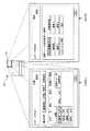
図1は、本発明の実施の形態による画像処理装置のハードウェア構成を示したブロック図である。本実施の形態による画像処理装置は、デジタル複合機(MFP)である。MFP100は、
演算機能、制御機能等を司るコンピュータであるコンピュータ主要部101と、
各種データを保持するためのデータ記憶部103と、
外部装置とのデータ送受信を行うためのインタフェース部105と、
画像を読み取って当該画像の電子データを生成する画像読取部107と、
画像の電子データに対し種々の画像処理を行う画像処理部109と、
画像処理された電子データを電子写真プロセスにより印刷出力する画像形成部111と、
操作者が設定入力や指示入力を行い、また、また設定された機能の確認や種々の警告等を表示するユーザインタフェース部121と、
を有する。
コンピュータ主要部101は、中央処理装置(CPU)113と、リード・オンリー・メモリ(ROM)115と、ランダム・アクセス・メモリ(RAM)117と、本体不揮発性メモリ(NVRAM)119とを有する。
CPU113は、各種プログラムを実行し、様々なデータ演算処理およびMFP本体の制御処理を行う。
ROM115は、CPU113が実行可能な各種プログラムを保持する。
RAM117は、CPU113が使用するデータを保持する。
本体NVRAM119は、電源切断時においても設定されたモード等のデータを保持するために用いられる。
また、ユーザインタフェース部121は、操作者に情報を提示するための表示部123および操作者がMFP100に対して設定や指示等を入力するための操作部125を備える。表示部123は、マルチビュー液晶を備え、操作者に対して同時的に複数の画面を提示することができる。操作者は自らの視方向を変化させることにより、当該複数の画面を参照する。操作部125は、マルチビュー液晶と一体的に構成されるタッチパネルを備える。
インタフェース部105は、ネットワーク200を介して他のMFP(MFP2ないしMFP4ならびにサーバ装置(301、303、305、307))とデータ送受信可能に通信したり、携帯記憶装置(USBメモリ300等)とデータ送受信したりすることが可能である。なお、本実施の形態によるMFP100は、インタフェース部105を介して各種プログラムを取得することができる。したがって、本発明にかかる作用を実現するためのプログラム等についても、インタフェース部105を介して取得し、実行可能である。(Hardware configuration)
FIG. 1 is a block diagram showing a hardware configuration of an image processing apparatus according to an embodiment of the present invention. The image processing apparatus according to the present embodiment is a digital multi-function peripheral (MFP). The
A computer
A
An
An
An
An
A
Have
The
The
The
The
The
The
(機能的構成)
図2は、本実施の形態によるMFP100の機能的構成を示すブロック図である。当該機能は、図1に示したハードウェア構成要素、および、コンピュータ主要部101において実行されるプログラムの協働的作用により実現される。(Functional configuration)
FIG. 2 is a block diagram showing a functional configuration of
MFP100は、
操作者が行った操作の内容を記録して各操作が使用された頻度を集計する操作頻度集計部131と、
ある時刻を起点とした時間の情報を出力するタイマ部133と、
表示部123に表示する画面を決定する表示画面決定部135と、
操作部125に対して操作者がした操作を受け付ける137と、
表示部123の画面を構成する複数の画面それぞれについての視野角を決定する視野角決定部139と、
視野角決定部139が決定した視野角の値に基づいて表示部の視野角を調整する視野角調整部141と、
表示画面決定部135が決定した画面を視野角決定部139が決定した視野角で表示する第1画面表示部143および第2画面表示部145と、
を有する。
表示画面決定部135は、マルチビュー液晶で構成される表示部123に表示する複数の画面の内容を決定し、その内容を表示部123へ出力する。
視野角決定部139は、第1画面表示部143に表示される第1画面の視野角および第2画面表示部145に表示される第2画面の視野角を決定する。
視野角調整部141は、マルチビュー液晶の視差バリア等を調整し、第1および第2画面の視野角を調整する。
なお、視野角とは、操作者が画面を参照可能な視方向の範囲である。The
An operation frequency totaling unit 131 that records the contents of operations performed by the operator and totals the frequency with which each operation was used;
A
A display
137 for accepting an operation performed by the operator on the
A viewing
A viewing
A first
Have
The display
The viewing
The viewing
The viewing angle is a range in the viewing direction in which the operator can refer to the screen.
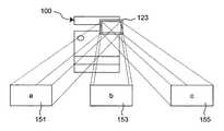
図3は、本実施の形態によるMFP100の表示部123におけるマルチ画面表示の概要を示す図である。MFP100は、表示部123において、同時的に複数の画面を表示する。操作者は、表示部123に対する視方向を変化させることにより、複数の画面の1つを参照することができる。たとえば、図面左右方向に関して第1画面151は、もっとも左に位置する視野角で表示される。第2画面153は、中央の視野角において参照可能である。第3画面155は、もっとも右に位置する視野角で表示される。操作者は、視方向を変化させることにより、同一表示面上にて、上記3種類の画面151、153、155を略同時的に(一切の操作を要さずに)参照することができる。 FIG. 3 is a diagram showing an outline of multi-screen display on
図4は、表示部123のマルチ画面表示の表示原理を示す図である。表示部123のマルチビュー液晶160は、画素161および視差バリア163を有する。本図においては、簡単のため、マルチビュー液晶は、2画面を同時的に表示するものとする。
ここで、画素161においては、所定の方向について、第1画面表示用画素161Lと第2画面表示用画素161Rとが交替的に配置されている。第1画面表示用画素161Lは、第1画面151(図3)を表示することに用いられ、第2画面表示用画素161Rは、第2画面153(図3)を表示することに用いられる。よって、画素161においては、所定の方向について、第1画面と第2画面とが縞状に表示されることになる。そして、画素161と操作者との間には、視差バリア163と呼ばれるスリット(フィルタ)が配される。視差バリア163は、光を透過する部分と光を遮断する部分とを有する。そのため、画素161からでた光は、所定の方向に対しては、視差バリア163について画素161の反対側へ透過することができるが、上記所定の方向以外の方向については、視差バリア163についての画素161の反対側へ透過することができない。このように、視差バリア163が所定の方向への画素161からの光の伝播を遮断することにより、各画素からの光を操作者が視認できる視野角が制御される。ここでは、第1画面表示用画素161Lから出る光は、図面左右方向の左側にのみ伝播することができ、第2画面表示用画素151Rから出る光は、同右側にのみ伝播することができる。よって、図面左右方向左側の視方向にあっては、操作者は、画面A(第1画面151)を視認し、同右側の視方向にあっては、操作者は、画面B(第2画面153)を視認する。FIG. 4 is a diagram illustrating the display principle of the multi-screen display of the
Here, in the
(複数階層画面同時表示処理フローチャート)
図5は、本実施の形態による画像処理装置における、複数階層画面の同時表示にかかる処理のフローチャートである。本例においては、マルチ画面表示として2つの画面(第1および第2画面)を表示するものとする(図4参照。)。(Multi-layer screen simultaneous display processing flowchart)
FIG. 5 is a flowchart of processing relating to simultaneous display of a plurality of hierarchical screens in the image processing apparatus according to the present embodiment. In this example, two screens (first and second screens) are displayed as multi-screen display (see FIG. 4).
ステップS101において、MFP100は、表示部123に、第1画面151(図3、図4)として基本画面を表示する。より一般的に本ステップを表現するならば、MFP100は、現在MFP100に設定されている内容(現在の動作モード、操作者による直前の操作入力、等)に基づいて、第1画面151の表示内容を決定する。ここで基本画面とは、各動作モードにおける最上位の階層に位置する画面である。 In step S101, the
図6は、基本画面の例としてコピー動作モードにおける基本画面を示す図である。ステップS101において、基本画面は、第1画面151として表示される。 FIG. 6 is a diagram showing a basic screen in the copy operation mode as an example of the basic screen. In step S101, the basic screen is displayed as the
図5に戻り、ステップS103において、MFP100は、表示部123に、第2画面53(図3、図4)として基本画面のひとつ下位にある画面を表示する。 Returning to FIG. 5, in step S <b> 103, the
図7は、基本画面のひとつ下位にある画面の例として用紙選択画面を示す図である。用紙選択画面は、図6の基本画面の「用紙」キー171が押下されることで選択される、基本画面のひとつ下位にある画面である。 FIG. 7 is a diagram illustrating a paper selection screen as an example of a screen that is one level lower than the basic screen. The paper selection screen is a screen that is one level lower than the basic screen and is selected by pressing the “paper” key 171 in the basic screen of FIG. 6.
このように、MFP100は、2画面からなるマルチ画面表示において、一方の画面が、他方の画面から選択可能なひとつ下位の画面になるように、表示部123の表示を制御する。なお、他方の画面から選択可能なひとつ下位の画面が複数存在する場合には、それらのうちの1つを表示する。 As described above, in the multi-screen display including two screens, the
図8は、本実施の形態によるMFP100におけるマルチ画面表示の状況を示す例図である。この状況において、操作者が図面左側から表示部123を参照すれば、操作者は、コピー動作モード基本画面を参照可能であり、図面右側から表示部123を参照すれば、操作者は、コピー動作モード基本画面から選択可能なひとつ下位の画面「用紙選択画面」を参照することができる。 FIG. 8 is an example diagram showing a state of multi-screen display in
図5に戻り、ステップS105において、MFP100は、第1画面の操作キーが押下されたか、否か、について判定する。
MFP100が、第1画面の操作キーが押下された、と判定した場合(ステップS105における「YES」)、処理は、ステップS107へ移行する。
MFP100が、第1画面の操作キーが押下されていない、と判定した場合(ステップS105における「NO」)、処理は、終了する。Returning to FIG. 5, in step S105, the
If
If
ステップS107において、MFP100は、ステップS105において押下された操作キーに設定された内容に従って、第1画面151の表示を更新する。たとえば、第1画面151における「用紙」キー171が押されたとする。その場合、MFP100は、その第1画面151として、「用紙選択画面」(図7参照。)を、第1画面151として表示する。 In step S107, the
そして、ステップS109において、MFP100は、第1画面151に表示されている画面の階層よりもひとつ下位にかかる画面を第2画面153に表示する。たとえば、第1画面として「用紙選択画面」(図7)が表示されていれば、第2画面153には、「用紙選択画面」から選択可能なひとつ下位にある画面である「選択トレーの設定変更画面」が表示される。 In step S <b> 109,
図9は、「用紙選択画面」(図7)のひとつ下位にある画面の例である「選択トレーの設定変更>1段目画面」を示す図である。このように、MFP100は、一方の画面に対する操作者の操作によって、一方の画面の表示が変更されると、常に、当該画面から選択可能なひとつ下位にある画面を他方の画面に表示する。こうすることにより、操作者は、視方向を変化させることで、同時的に(何らMFP100に対して操作を行うことなしに)、複数の階層の画面を参照することができ、容易に設定操作を行うことが可能になる。 FIG. 9 is a diagram showing “selection tray setting change> first stage screen” which is an example of a screen one level lower than the “paper selection screen” (FIG. 7). As described above, when the display of one screen is changed by the operator's operation on one screen,
図10は、本実施の形態によるMFP100におけるマルチ画面表示の状況を示す例図である。この状況において、操作者が図面左側から表示部123を参照すれば、操作者は、「用紙選択画面」を参照可能であり、図面右側から表示部123を参照すれば、操作者は、「用紙選択画面」から選択可能なひとつ下位の画面「選択トレーの設定変更>1段目画面」を参照することができる。 FIG. 10 is a view showing an example of a multi-screen display state in
なお、本実施の形態によるMFP100にあっては、第1画面151(第1画面表示部143)と第2画面153(第2画面表示部145)とは、操作部(タッチパネル)125を共用する。したがって、第1画面表示部143と第2画面表示部145とに同時的に表示される画面同士の関係にあっては、両画面に配置される操作キーは、位置をずらして配される。そうすることで、MFP100は、タッチパネルに対してなされた操作がいずれの画面のどの操作キーに対する操作であるか、を正確に把握することが可能である。 In
(操作頻度集計量に基づく選択的下位階層画面表示処理フローチャート)
次に、図11を参照し、下位階層画面が複数存在する場合において、複数の画面から表示部123に表示するための画面を選択するために行う処理について説明する。(Selective lower-level screen display processing flowchart based on operation frequency total amount)
Next, with reference to FIG. 11, a description will be given of processing performed for selecting a screen to be displayed on the
図11は、操作頻度集計量に基づく選択的下位階層画面選択を示すフローチャートである。 FIG. 11 is a flowchart showing selective lower hierarchy screen selection based on the operation frequency total amount.
ステップS101において、MFP100は、表示部123に、第1画面151(図3、図4)として基本画面(図6)を表示する。図6を参照すれば、基本画面から選択可能なひとつ下位の画面には、カラー選択画面、用紙選択画面、倍率設定画面、両面/ページ集約設定画面等があることが理解される。 In step S101, the
そこで、MFP100は、ステップS203において、第2画面153として表示すべき下位画面の優先順位を求め、当該順位に応じて、第2画面153を構成する。当該優先順位は、使用される可能性が高い画面が上位になるように決定される。また、使用される可能性は、過去の操作実績に基づいて決定される。具体的には、MFP100は、操作頻度集計部131が出力する操作頻度集計量を参照し、優先順位を決定する。なお、操作頻度集計部131は、操作者による過去の操作について、操作頻度を示す量を出力可能である。当該量は、所定の統計量であればよい。 In step S203, the
ステップS205において、MFP100は、優先順位が高い下位画面を、第2画面153として、表示部123の第2画面表示部145に表示する。 In step S <b> 205, the
このようにして、複数の下位画面がある場合に、第2画面153として表示するべき下位画面を決定することで、操作者は、実際に操作する必要がある下位画面を、何らMFP100を操作することなく、基本画面と同時的に参照可能になる。 In this way, when there are a plurality of lower screens, by determining the lower screen to be displayed as the
(タイマ駆動による選択的下位階層画面表示処理フローチャート)
次に、時間経過に沿って自動的に下位画面として表示する画面を切り替える下位画面表示形態について説明する。図12は、タイマ駆動による選択的下位階層画面表示処理のフローチャートである。(Timer driven selective lower layer screen display processing flowchart)
Next, a lower screen display mode for switching a screen to be displayed as a lower screen automatically with the passage of time will be described. FIG. 12 is a flowchart of selective lower layer screen display processing by timer driving.
ステップS101において、MFP100は、表示部123に、第1画面151(図3、図4)として基本画面(図6)を表示する。図6を参照すれば、基本画面から選択可能なひとつ下位の画面には、カラー選択画面、用紙選択画面、倍率設定画面、両面/ページ集約設定画面等があることが理解される。 In step S101, the
ステップS303において、MFP100は、タイムカウンタの値(T)をゼロに設定する。MFP100は、このときにタイマ部133が出力した値を、値T=ゼロと関係づけて記憶する。 In step S303, the
ステップS305において、MFP100は、タイムカウンタの値Tに基づいて、処理を分岐させる。たとえば、タイムカウンタの値Tが、ゼロ以上10未満(単位は、たとえば、[秒]でよい。)の場合、処理は、ステップS307へ移行し、タイムカウンタの値Tが、10以上20未満の場合、処理は、ステップS309へ移行し、タイムカウンタの値Tが、20以上の場合、処理は、ステップS311へ移行する。 In step S305, the
ステップS307においては、第2画面153として用紙選択画面(図7)が表示される。 In step S307, the paper selection screen (FIG. 7) is displayed as the
ステップS309においては、第2画面153としてカラー選択画面(図示せず。)が表示される。 In step S309, a color selection screen (not shown) is displayed as the
ステップS311においては、第2画面153として両面/ページ集約設定画面(図示せず。)が表示される。 In step S311, a double-sided / page aggregation setting screen (not shown) is displayed as the
このように、MFP100は、一方の画面に表示されている画面から選択可能なひとつ下位の画面について、時間的に、表示する下位画面を切り替えて順次表示する。本例においては、基本画面の下位画面である「用紙選択画面」、「カラー選択画面」、「両面/ページ集約設定画面」が、この順番で、自動的に定期的に切り替わる。これは、操作者が、コピージョブの設定をする場合に、用紙を選択し、カラーを選択し、両面/ページ集約設定をする、という順で設定操作をすることが多いと考えられるからである。このように、第2画面153を時間的に自動的に切り換えることで、操作者は、その順に設定操作を行うことで、一通りの設定操作を済ますことがでるため、設定操作において操作に迷うことがなくなる。基本画面以外の画面が第1画面151または第2画面153に表示されている場合も、同様の趣旨で、操作者の利便性に資するように、時間的に他方の画面に表示するひとつ下位の画面を切り替えればよい。 As described above, the
ステップS313において、MFP100は、タイマ部133の出力を参照し、タイムカウンタの値Tを更新する。値Tの単位を[秒]とする場合、ステップS313におけるタイマ部133の出力と、T=ゼロにおけるタイマ部133との差[秒]を用いて値Tの値を更新する。 In step S313, the
ステップS315において、MFP100は、タイムカウンタの値Tが、30以上であるか、否か、について判定する。
MFP100が、タイムカウンタの値Tは30以上である、と判定した場合(ステップS315における「YES」)、処理は、ステップS317へ移行する。
MFP100が、タイムカウンタの値Tは30未満である、と判定した場合(ステップS315における「NO」)、処理は、ステップS317をスキップしてステップS319へ移行する。In step S315, the
If
If
ステップS317において、MFP100は、タイムカウンタの値Tをリセットする。ステップS317の処理は、ステップS303の処理と同様に行えばよい。ここでは、MFP100は、10秒間隔で、3種類の下位画面を切り替えるため、周期30秒ごとにタイムカウンタの値Tをリセットしている。30秒と異なる周期の場合には、ステップS317は、タイムカウンタの値Tが周期に対応した値を超えた場合に、タイムカウンタの値をリセットすればよい。 In step S317, the
ステップS319において、MFP100は、第1画面151に対する操作の有無を判定する。第1画面に対して操作がなされた場合(ステップS319における「YES」)、処理は、終了する。第1画面に対して操作がなされていない限り(ステップS319における「NO」)、処理は、ステップS305へ戻り、ループする。 In step S319, the
(操作者設定による画面表示処理)
本実施の形態によるMFP100においては、操作者が、あらかじめ、第2画面153としてどのような画面を表示するかを設定することも可能である。この場合、第2画面153は、第1画面151との関係において、第1画面151から選択可能なひとつ下位の画面でなくともよい。(Screen display processing by operator settings)
In
図13は、コピー動作モードにおける基本画面の例を示す図である。基本画面には、操作キー「右画面の表示設定」173が設けられている。ここで、右画面とは、第2画面153を指す。操作キー173が押下された場合に表示される画面の例を図14に示す。図14に示す画面は、第1もしくは第2画面のいずれに表示されてもよい。 FIG. 13 is a diagram illustrating an example of a basic screen in the copy operation mode. An operation key “right screen display setting” 173 is provided on the basic screen. Here, the right screen refers to the
図14は、右画面の表示内容設定画面である。操作者は、操作キー「表示しない」、「操作設定表示」、「設定一覧表示」、「仕上がりイメージ表示」、「ガイダンス表示」のいずれかひとつを選択することにより、第2画面153に表示される画面を指定することができる。
操作キー「表示しない」が選択された場合には、第2画面153には何も表示されない。
操作キー「操作設定表示」が選択された場合には、図8を参照して説明したように、第2画面153として、第1画面151から選択可能な下位画面のひとつが表示される。FIG. 14 is a display content setting screen on the right screen. The operator selects one of the operation keys “not display”, “operation setting display”, “setting list display”, “finished image display”, and “guidance display” to display on the
When the operation key “not display” is selected, nothing is displayed on the
When the operation key “display operation setting” is selected, as described with reference to FIG. 8, one of the lower screens selectable from the
(設定一覧画面表示)
図15は、操作キー「設定一覧表示」が選択された場合に、第2画面153に表示される設定一覧表示画面の例図である。このように、第2画面153には、現在設定されている値の一覧が表示される。(Setting list screen display)
FIG. 15 is an example of a setting list display screen displayed on the
(仕上がりイメージ表示)
図16は、操作キー「仕上がりイメージ表示」が選択された場合に、第2画面153に表示される仕上がりイメージ表示画面の例図である。このように、第2画面には、現在設定されている値による実行ジョブの仕上がりイメージがグラフィカルに表示される。図16では、第1画面151の「ページ集約」において「2in1」が選択されており、これに応じて第2画面153には2ページ分の画像が1ページに集約されている仕上がりイメージが表示されている。(Finished image display)
FIG. 16 is an example of a finished image display screen displayed on the
(ガイダンス画面表示)
図17は、操作キー「ガイダンス表示」が選択された場合に、第2画面153に表示されるガイダンス表示画面の例図である。このように、第2画面には、現在第1画面151として表示されている内容に関連したガイダンスが表示される。(Guidance screen display)
FIG. 17 is an example of a guidance display screen displayed on the
(操作者設定による画面表示処理フローチャート)
図18は、操作者設定による画面表示のフローチャートである。(Screen display processing flowchart by operator setting)
FIG. 18 is a flowchart of screen display by operator setting.
ステップS101において、MFP100は、表示部123に、第1画面151(図3、図4)として基本画面(図6)を表示する。 In step S101, the
ステップS403において、MFP100は、操作者設定した第2画面(右画面)表示内容設定に基づいて、処理を分岐させる。
操作者が、「表示しない」を選択している場合(ステップS403における「設定値=表示しない」)、処理は、ステップS405へ移行する。
操作者が、「操作設定表示」を選択している場合(ステップS403における「設定値=操作設定表示」)、処理は、ステップS407へ移行する。
操作者が、「設定一覧表示」を選択している場合(ステップS403における「設定値=設定一覧表示」)、処理は、ステップS409へ移行する。
操作者が、「仕上がりイメージ表示」を選択している場合(ステップS403における「設定値=仕上がりイメージ表示」)、処理は、ステップS411へ移行する。
操作者が、「ガイダンス表示」を選択している場合(ステップS403における「設定値=ガイダンス表示」)、処理は、ステップS413へ移行する。In step S403,
When the operator has selected “not display” (“set value = not display” in step S403), the process proceeds to step S405.
If the operator has selected “operation setting display” (“setting value = operation setting display” in step S403), the process proceeds to step S407.
When the operator has selected “setting list display” (“setting value = setting list display” in step S403), the process proceeds to step S409.
If the operator has selected “finished image display” (“set value = finished image display” in step S403), the process proceeds to step S411.
When the operator has selected “guidance display” (“setting value = guidance display” in step S403), the process proceeds to step S413.
このように、本実施の形態によるMFP100においては、操作者が、第2画面153として表示させる内容をあらかじめ設定することが可能である。 As described above, in
(表示内容に応じた視野角制御処理)
本実施の形態によるMFP100は、表示している画面の内容に応じ、当該画面を視認可能な視方向の範囲(視野角)を調整する。そうすることによって、操作者が誤操作することを未然に防止する。(Viewing angle control processing according to display contents)
たとえば、第1画面151および第2画面153共に、操作設定用の画面(たとえば、図7のような用紙選択画面)を表示するような場合、第2画面153は、第1画面151と同様に、操作者によって操作される操作キーを備えている。このような場合には、MFP100は、第2画面153の視野角が、第1画面151の視野角と同等程度になるように、視野角の調整を行う。また、第2画面153が、操作者に情報を提示することのみを目的とするような画面(たとえば、図17のようなガイダンス画面)を表示する場合、操作者が第2画面153を用いて操作を行うことはないので、第2画面153の視野角が、第1画面151の視野角よりも狭くなるように、視野角の調整を行う。 For example, when both the
(表示内容に応じた視野角制御処理のフローチャート)
図19は、表示内容に応じた視野角制御処理のフローチャートである。(Flow chart of viewing angle control processing according to display contents)
FIG. 19 is a flowchart of the viewing angle control process corresponding to the display content.
ステップS101において、MFP100は、表示部123に、第1画面151(図3、図4)として基本画面(図6)を表示する。 In step S101, the
ステップS503において、MFP100は、第2画面153の表示内容が操作設定用の画面であるか、否か、について判定する。
MFP100が、第2画面153の表示内容は操作設定用の画面である、と判定した場合(ステップS503における「YES」)、処理は、ステップS505へ移行する。
MFP100が、第2画面153の表示内容は操作設定用の画面ではない、と判定した場合(ステップS503における「NO」)、処理は、ステップS507へ移行する。In step S503, the
If
If
図20に、視野角調整の原理を説明するための図を示す。図20(a)は、広視野角に調整された状態を示す図であり、図20(b)は、広視野角よりも狭い狭視野角に調整された状態を示す図である。
本例においては、マルチビュー液晶160の操作者側に、さらに、スイッチ液晶180が一体的に配されている。そして、スイッチ液晶180の画素の一部を、光を透過しない状態にスイッチすることにより、マルチビュー液晶160から出た光の一部を操作者側に到達しないようにし、もって、視野角の調整を行っている。
また、このようなスイッチ液晶を複数持てば、動作させるスイッチ液晶を切り替えることで視野角を多段的に切り替えることも可能である。FIG. 20 is a diagram for explaining the principle of viewing angle adjustment. FIG. 20A is a diagram showing a state adjusted to a wide viewing angle, and FIG. 20B is a diagram showing a state adjusted to a narrow viewing angle narrower than the wide viewing angle.
In this example, the
If a plurality of such switch liquid crystals are provided, the viewing angle can be switched in multiple stages by switching the switch liquid crystals to be operated.
なお、視野角の調整は、図20の例に限らず、視差バリア163の光透過部分および光遮断部分のピッチを可変的に制御したり、画素161(図4)と視差バリア163との間隔を画素161のなす面と垂直な方向、あるいは、平行な方向に可変的に制御したりすることで、調整することも可能である。 Note that the adjustment of the viewing angle is not limited to the example in FIG. 20, and the pitch between the light transmitting part and the light blocking part of the
なお、上述した、複数階層画面同時表示処理(図5)、操作頻度集計量に基づく選択的下位階層画面表示処理(図11)、タイマ駆動による選択的下位階層画面表示処理(図12)、操作者設定による画面表示処理(図18)、表示内容に応じた視野角制御処理(図19)は、それぞれ、独立して実行可能な処理である。だが、これらの2つ以上を適宜組み合わせて1つの処理体系を実現することも可能である。その実現の方法については、当業者にとっては、容易な事柄であるため、説明を省略する。 It should be noted that the above-described multiple layer screen simultaneous display processing (FIG. 5), selective lower layer screen display processing based on the operation frequency total amount (FIG. 11), timer-driven selective lower layer screen display processing (FIG. 12), operation The screen display process (FIG. 18) based on the user setting and the viewing angle control process (FIG. 19) according to the display contents can be independently executed. However, one processing system can be realized by appropriately combining two or more of these. The method for realizing this is an easy matter for those skilled in the art and will not be described.
本発明の構成によると、操作者が液晶の分割された視野角に移動するだけで、異なる階層の複数の画面を見ることが可能である。これにより、操作者の操作性が向上される。 According to the configuration of the present invention, it is possible for the operator to view a plurality of screens at different levels simply by moving to the divided viewing angle of the liquid crystal. Thereby, the operability of the operator is improved.
本発明は、画像処理装置として有用である。本発明にかかる画像処理装置は、操作者の操作の利便性が向上されており、誤操作の低減、操作に要する時間の短縮化といった効果を奏する。 The present invention is useful as an image processing apparatus. The image processing apparatus according to the present invention is improved in the convenience of operation by the operator, and has the effects of reducing erroneous operations and shortening the time required for operations.
100 ・・・ デジタル複合機(MFP)
101 ・・・ コンピュータ主要部
121 ・・・ ユーザインタフェース部
123 ・・・ 表示部
125 ・・・ 操作部
131 ・・・ 操作頻度集計部
133 ・・・ タイマ部
135 ・・・ 表示画面決定部
137 ・・・ 操作受付部
139 ・・・ 視野角決定部
141 ・・・ 視野角調整部
143 ・・・ 第1画面表示部
145 ・・・ 第2画面表示部
151 ・・・ 第1画面
153 ・・・ 第2画面
155 ・・・ 第3画面
160 ・・・ マルチビュー液晶
161 ・・・ 画素
163 ・・・ 視差バリア
180 ・・・ スイッチ液晶100: Digital MFP (MFP)
DESCRIPTION OF
Claims (5)
Translated fromJapanese同一画面上に、互いに視方向が異なるよう表示される第1画面および第2画面を含む少なくとも2つの画面を同時的に表示するユーザインタフェース表示部と、
設定操作の入力を受けるユーザインタフェース操作部と、
前記第1画面および前記第2画面の内容を決定する表示画面決定部とを有し、
前記表示画面決定部は、自機に設定されている内容に基づいて、前記第1画面を決定し、決定した前記第1画面から選択可能なひとつ下位の階層にある複数の画面のうちの1つを前記第2画面に自動的に決定し、当該決定に基づいて、前記ユーザインタフェース表示部に前記第1画面および前記第2画面を表示させる、画像処理装置。An image processing apparatus having a user interface screen composed of a plurality of screens having a hierarchical structure,
A user interface display unit for simultaneously displaying at least two screens including a first screen and a second screen displayed on the same screen so that their viewing directions are different from each other;
A user interface operation unit for receiving an input of a setting operation;
A display screen determining unit that determines the contents of the first screen and the second screen;
The display screen determination unit determines the first screen based on the content set in the own device, and selects one of a plurality of screens in one lower hierarchy selectable from the determined first screen. An image processing apparatus thatautomatically determines the first screen as the second screen and causes the user interface display unit to display the first screen and the second screen based on the determination.
前記表示画面決定部は、前記表示する操作の入力にかかる前記ひとつ下位の階層の画面を前記第1画面に決定し、決定した前記第1画面から選択可能なひとつ下位の階層の画面を前記第2画面に決定する、請求項1に記載の画像処理装置。When an input of an operation for displaying a screen of one lower hierarchy selectable from the first screen is received via the user interface operation unit,
The display screen determining unit determines the screen of the one lower layer related to the input of the operation to be displayed as the first screen, and selects the screen of the one lower layer selectable from the determined first screen as the first screen. The image processing apparatus according to claim 1, wherein the image processing apparatus determines two screens.
前記表示画面決定部は、前記操作頻度集計部がする頻度の集計に基づいて、前記ひとつ下位の階層にある複数の画面のうちで頻度が高い画面を前記第2画面に決定する、請求項1または2に記載の画像処理装置。Furthermore, an operation frequency totaling unit that records the input of the setting operation and totals the frequency required for the input of each setting operation,
The display screen determination unit determines a screen having a high frequency among the plurality of screens in the one lower hierarchy as the second screen based on the frequency aggregation performed by the operation frequency aggregation unit. Or the image processing apparatus of 2.
前記表示画面決定部は、前記タイマ部から出力される時間情報に基づいて、所定の期間ごとに画面を切り替えるように前記ひとつ下位の階層にある複数の画面のうちから前記第2画面を決定する、請求項1または2に記載の画像処理装置。Furthermore, it has a timer unit that measures time,
The display screen determination unit determines the second screen from the plurality of screens in the one lower hierarchy so as to switch the screen every predetermined period based on the time information output from the timer unit. The image processing apparatus according to claim 1 or 2.
前記第1画面および前記第2画面は、それぞれ、操作キーを含み、前記第1画面に含まれる操作キーの配置位置と、前記第2画面に含まれる操作キーの配置位置とは、前記同一画面上において、互いに相異なる位置である、請求項1から4のいずれか1つに記載の画像処理装置。The user interface operation unit is a touch panel configured integrally with the interface display unit,
The first screen and the second screen each include an operation key, and an operation key arrangement position included in the first screen and an operation key arrangement position included in the second screen are the same screen. The image processing apparatus according to claim 1, wherein the positions are different from each other.
Priority Applications (3)
| Application Number | Priority Date | Filing Date | Title |
|---|---|---|---|
| JP2009136216AJP5093190B2 (en) | 2009-06-05 | 2009-06-05 | Image processing device |
| CN2010101990212ACN101907973A (en) | 2009-06-05 | 2010-06-04 | Image processing equipment |
| US12/793,944US20100313163A1 (en) | 2009-06-05 | 2010-06-04 | Image processing apparatus |
Applications Claiming Priority (1)
| Application Number | Priority Date | Filing Date | Title |
|---|---|---|---|
| JP2009136216AJP5093190B2 (en) | 2009-06-05 | 2009-06-05 | Image processing device |
Publications (2)
| Publication Number | Publication Date |
|---|---|
| JP2010282478A JP2010282478A (en) | 2010-12-16 |
| JP5093190B2true JP5093190B2 (en) | 2012-12-05 |
Family
ID=43263444
Family Applications (1)
| Application Number | Title | Priority Date | Filing Date |
|---|---|---|---|
| JP2009136216AExpired - Fee RelatedJP5093190B2 (en) | 2009-06-05 | 2009-06-05 | Image processing device |
Country Status (3)
| Country | Link |
|---|---|
| US (1) | US20100313163A1 (en) |
| JP (1) | JP5093190B2 (en) |
| CN (1) | CN101907973A (en) |
Families Citing this family (8)
| Publication number | Priority date | Publication date | Assignee | Title |
|---|---|---|---|---|
| JP4891372B2 (en)* | 2009-07-28 | 2012-03-07 | シャープ株式会社 | Image forming apparatus |
| JP4880730B2 (en)* | 2009-08-03 | 2012-02-22 | シャープ株式会社 | Image communication apparatus and image forming apparatus having the same |
| JP5532018B2 (en)* | 2011-06-27 | 2014-06-25 | コニカミノルタ株式会社 | Terminal device, program, and remote operation system |
| JP5931373B2 (en)* | 2011-08-30 | 2016-06-08 | 株式会社東芝 | Medical diagnostic imaging apparatus and magnetic resonance imaging apparatus |
| JP5712942B2 (en)* | 2012-01-30 | 2015-05-07 | コニカミノルタ株式会社 | Image forming system, remote control device, image forming device, program |
| CN103698933B (en)* | 2013-12-30 | 2017-03-29 | 京东方科技集团股份有限公司 | three-dimensional display |
| JP6200371B2 (en)* | 2014-04-24 | 2017-09-20 | 株式会社沖データ | Image processing apparatus and image forming apparatus |
| CN114141132B (en)* | 2022-01-30 | 2022-05-03 | 广州长嘉电子有限公司 | Advertising machine and advertising directional display method |
Family Cites Families (13)
| Publication number | Priority date | Publication date | Assignee | Title |
|---|---|---|---|---|
| US6791703B1 (en)* | 1909-06-05 | 2004-09-14 | Canon Kabushiki Kaisha | Image processing apparatus and method, and storage medium therefor |
| CA2095452C (en)* | 1993-05-04 | 1997-03-18 | Phillip J. Beaudet | Dynamic hierarchical selection menu |
| WO1996009579A1 (en)* | 1994-09-22 | 1996-03-28 | Izak Van Cruyningen | Popup menus with directional gestures |
| DE69811203T2 (en)* | 1997-10-28 | 2003-11-13 | Koninkl Philips Electronics Nv | INFORMATION PROCESSING SYSTEM |
| JP2001352497A (en)* | 2000-06-08 | 2001-12-21 | Canon Inc | Control device |
| US20040100504A1 (en)* | 2002-05-24 | 2004-05-27 | Jored Sommer | Item selection systems and methods of displaying the same |
| GB2402587B (en)* | 2003-06-02 | 2006-09-13 | Yisia Young Suk Lee | A hand held display device and method |
| JP4074233B2 (en)* | 2003-09-02 | 2008-04-09 | シャープ株式会社 | Portable device |
| GB2407746B (en)* | 2003-10-28 | 2008-01-23 | Yisia Young Suk Lee | Method and apparatus for retrieving information from an informtion source |
| JP2007226461A (en)* | 2006-02-22 | 2007-09-06 | Sharp Corp | Input devices, electrical equipment |
| JP4425867B2 (en)* | 2006-02-22 | 2010-03-03 | シャープ株式会社 | Display device, printing device |
| US7728824B2 (en)* | 2006-02-22 | 2010-06-01 | Sharp Kabushiki Kaisha | Display device, input device, printing device, and electric device |
| JP5030212B2 (en)* | 2007-04-04 | 2012-09-19 | シャープ株式会社 | Display device for operation panel, image forming apparatus |
- 2009
- 2009-06-05JPJP2009136216Apatent/JP5093190B2/ennot_activeExpired - Fee Related
- 2010
- 2010-06-04USUS12/793,944patent/US20100313163A1/ennot_activeAbandoned
- 2010-06-04CNCN2010101990212Apatent/CN101907973A/enactivePending
Also Published As
| Publication number | Publication date |
|---|---|
| JP2010282478A (en) | 2010-12-16 |
| US20100313163A1 (en) | 2010-12-09 |
| CN101907973A (en) | 2010-12-08 |
Similar Documents
| Publication | Publication Date | Title |
|---|---|---|
| JP5093190B2 (en) | Image processing device | |
| CN102164222B (en) | Operating devices, electronic devices and image processing devices | |
| US10063722B2 (en) | Image forming apparatus configured to display function setting buttons and switch display mode between first display mode and second display mode and image recording medium | |
| US8648820B2 (en) | Operation console, electronic equipment and image processing apparatus with the console, and operation method | |
| CN104902133B (en) | Operate equipment, electronic equipment, image forming apparatus and information display method | |
| JP5790402B2 (en) | Image processing apparatus and program | |
| US8643567B2 (en) | Multi-layer display | |
| US20180213097A1 (en) | Device | |
| EP2551760B1 (en) | Operation apparatus, image forming apparatus, display control method, program, and medium for recording the program | |
| US20190075211A1 (en) | Multifunction peripheral | |
| EP3037943B1 (en) | Display/input device, image forming apparatus, and method for controlling a display/input device | |
| JP2013114338A (en) | Operation device and operation method | |
| JP2007293511A (en) | Input device and image forming apparatus | |
| JP5849779B2 (en) | Operation input device for image forming apparatus, operation screen display control method and program executed by input device | |
| JP6221646B2 (en) | Image processing apparatus and input receiving apparatus | |
| JP5716515B2 (en) | An image forming apparatus including an operation display device, a display control program, and an operation display device. | |
| CN110971774A (en) | Display device, storage medium, and control method of display device | |
| JP5664321B2 (en) | Image forming system and program | |
| JP2006201585A (en) | Operation panel device | |
| EP2669744B1 (en) | Image forming apparatus | |
| JP2010243800A (en) | Image processing device | |
| CN108376049B (en) | Display device and display program | |
| JP2009033263A (en) | Display controller of image forming apparatus | |
| JP2009058612A (en) | Image forming apparatus and display control program | |
| JP2007142638A (en) | Image forming apparatus |
Legal Events
| Date | Code | Title | Description |
|---|---|---|---|
| A977 | Report on retrieval | Free format text:JAPANESE INTERMEDIATE CODE: A971007 Effective date:20110421 | |
| A131 | Notification of reasons for refusal | Free format text:JAPANESE INTERMEDIATE CODE: A131 Effective date:20110510 | |
| A521 | Request for written amendment filed | Free format text:JAPANESE INTERMEDIATE CODE: A523 Effective date:20110707 | |
| A131 | Notification of reasons for refusal | Free format text:JAPANESE INTERMEDIATE CODE: A131 Effective date:20111115 | |
| A521 | Request for written amendment filed | Free format text:JAPANESE INTERMEDIATE CODE: A523 Effective date:20120112 | |
| TRDD | Decision of grant or rejection written | ||
| A01 | Written decision to grant a patent or to grant a registration (utility model) | Free format text:JAPANESE INTERMEDIATE CODE: A01 Effective date:20120821 | |
| A01 | Written decision to grant a patent or to grant a registration (utility model) | Free format text:JAPANESE INTERMEDIATE CODE: A01 | |
| A61 | First payment of annual fees (during grant procedure) | Free format text:JAPANESE INTERMEDIATE CODE: A61 Effective date:20120903 | |
| R150 | Certificate of patent or registration of utility model | Free format text:JAPANESE INTERMEDIATE CODE: R150 | |
| FPAY | Renewal fee payment (event date is renewal date of database) | Free format text:PAYMENT UNTIL: 20150928 Year of fee payment:3 | |
| S111 | Request for change of ownership or part of ownership | Free format text:JAPANESE INTERMEDIATE CODE: R313111 | |
| R350 | Written notification of registration of transfer | Free format text:JAPANESE INTERMEDIATE CODE: R350 | |
| LAPS | Cancellation because of no payment of annual fees |