JP5093185B2 - Inverted moving body control device - Google Patents
Inverted moving body control deviceDownload PDFInfo
- Publication number
- JP5093185B2 JP5093185B2JP2009109591AJP2009109591AJP5093185B2JP 5093185 B2JP5093185 B2JP 5093185B2JP 2009109591 AJP2009109591 AJP 2009109591AJP 2009109591 AJP2009109591 AJP 2009109591AJP 5093185 B2JP5093185 B2JP 5093185B2
- Authority
- JP
- Japan
- Prior art keywords
- load angle
- moving body
- torque
- load
- inverted
- Prior art date
- Legal status (The legal status is an assumption and is not a legal conclusion. Google has not performed a legal analysis and makes no representation as to the accuracy of the status listed.)
- Expired - Fee Related
Links
Images


Classifications
- G—PHYSICS
- G05—CONTROLLING; REGULATING
- G05D—SYSTEMS FOR CONTROLLING OR REGULATING NON-ELECTRIC VARIABLES
- G05D1/00—Control of position, course, altitude or attitude of land, water, air or space vehicles, e.g. using automatic pilots
- G05D1/08—Control of attitude, i.e. control of roll, pitch, or yaw
- G05D1/0891—Control of attitude, i.e. control of roll, pitch, or yaw specially adapted for land vehicles
- B—PERFORMING OPERATIONS; TRANSPORTING
- B62—LAND VEHICLES FOR TRAVELLING OTHERWISE THAN ON RAILS
- B62K—CYCLES; CYCLE FRAMES; CYCLE STEERING DEVICES; RIDER-OPERATED TERMINAL CONTROLS SPECIALLY ADAPTED FOR CYCLES; CYCLE AXLE SUSPENSIONS; CYCLE SIDE-CARS, FORECARS, OR THE LIKE
- B62K11/00—Motorcycles, engine-assisted cycles or motor scooters with one or two wheels
- B62K11/007—Automatic balancing machines with single main ground engaging wheel or coaxial wheels supporting a rider
Landscapes
- Engineering & Computer Science (AREA)
- Aviation & Aerospace Engineering (AREA)
- Radar, Positioning & Navigation (AREA)
- Remote Sensing (AREA)
- Physics & Mathematics (AREA)
- General Physics & Mathematics (AREA)
- Automation & Control Theory (AREA)
- Mechanical Engineering (AREA)
- Control Of Position, Course, Altitude, Or Attitude Of Moving Bodies (AREA)
- Motorcycle And Bicycle Frame (AREA)
Description
Translated fromJapanese本発明は、倒立型移動体の制御装置に関する。詳しくは、車輪駆動手段とリンク状の負荷体とを備え、リンク状の負荷体を倒立させるバランス制御を行いながら移動する倒立型移動体の制御装置に関する。 The present invention relates to an inverted moving body control device. More specifically, the present invention relates to an inverted moving body control device that includes wheel driving means and a link-like load body and moves while performing balance control for inverting the link-like load body.
同軸に設けられた左右一対の車輪を有し、倒立状態を維持しながら走行する移動装置が知られている。たとえば、特許文献1(特開2006−123014号公報)には、倒立状態を維持しながら自律的に走行する倒立二輪走行ロボットが開示されている。また、特許文献2(特開2006-315666号公報)には、人が立位姿勢でステップに搭乗した状態でバランスを保ちながら走行する同軸二輪車が開示されている。 2. Description of the Related Art A moving device that has a pair of left and right wheels provided coaxially and travels while maintaining an inverted state is known. For example, Patent Document 1 (Japanese Patent Laid-Open No. 2006-123014) discloses an inverted two-wheeled traveling robot that autonomously travels while maintaining an inverted state. Patent Document 2 (Japanese Patent Laid-Open No. 2006-315666) discloses a coaxial two-wheeled vehicle that travels while maintaining a balance while a person is on a step in a standing posture.
図10は、特許文献1に開示された倒立二輪走行ロボットの制御器の構成を示す図である。
図10において、1001は摩擦推定器、1002は目標状態生成器、1003は状態フィードバックゲイン、1004は倒立ロボットである。
摩擦推定器1001には角速度指令値が入力され、摩擦推定器1001は、モータの摩擦および車輪と路面との摩擦を摩擦推定値として算出し出力する。
目標状態生成器1002には前記角速度指令値と前記摩擦推定値とが入力され、目標状態生成器1002は、制御対象である倒立ロボット1004の目標状態を算出し出力する。
状態フィードバックゲイン1003には、前記目標状態から倒立ロボット1004の状態変数を減算した信号が入力され、状態フィードバックゲイン1003は、その入力信号に基づいて倒立ロボット1004に所望の動作をさせる状態フィードバック信号を算出して出力する。
倒立ロボット1004は、前記摩擦推定値と前記状態フィードバック信号との加算値により駆動される。
このように、従来技術の倒立二輪走行ロボットの制御では、制御対象である倒立ロボット1004を所望の姿勢の近傍で線形化した線形化モデルに基づいて倒立ロボット1004の動作を制御している。FIG. 10 is a diagram showing the configuration of the controller of the inverted two-wheeled robot disclosed in
In FIG. 10, 1001 is a friction estimator, 1002 is a target state generator, 1003 is a state feedback gain, and 1004 is an inverted robot.
The angular velocity command value is input to the
The
A signal obtained by subtracting the state variable of the inverted
The inverted
As described above, in the control of the inverted two-wheeled robot of the prior art, the operation of the inverted
上記に説明したように、従来の倒立制御では、単純な線形フィードバック制御を行っているが、倒立ロボットや同軸二輪車では、同軸車輪の上に長いリンクが設けられた構造を有しているので、負荷であるリンク部分が目標姿勢で安定せずに揺れやすいという特徴がある。
このような構成に対して、従来のように目標姿勢からの偏差に応じたフィードバックをかけ続けると、目標姿勢で安定せずに目標の近傍で振動が起きてしまうという問題があった。
なお、従来は、このような目標近傍での振動に対し、振動を抑えるようにフィードバックゲインを調整していたが、目標から大きく離れた場合には倒れてしまわないように素早く目標姿勢に復帰させる一方で、目標近傍では発振を防ぐという制御を単純なフィードバックゲインの調整だけで行うには無理があった。As described above, in the conventional inverted control, simple linear feedback control is performed, but the inverted robot and the coaxial two-wheeled vehicle have a structure in which a long link is provided on the coaxial wheel. The link part which is a load has the feature that it is easy to shake without being stabilized in the target posture.
For such a configuration, if feedback according to the deviation from the target posture is continuously applied as in the conventional case, there is a problem that vibration occurs near the target without being stabilized in the target posture.
In the past, the feedback gain was adjusted so as to suppress the vibration in the vicinity of the target. However, when the distance is far from the target, the target posture is quickly restored so that it does not fall down. On the other hand, it has been impossible to perform control for preventing oscillation near the target by simply adjusting the feedback gain.
本発明の目的は、発振させることなく安定した倒立バランス制御を行いつつ所望の水平速度で走行させることができる倒立型移動体の制御装置を提供することにある。 An object of the present invention is to provide a control device for an inverted moving body that can be driven at a desired horizontal speed while performing stable inverted balance control without oscillation.
上記問題を解決するため、本発明は、次のように構成したのである。
すなわち、本発明の倒立型移動体の制御装置は、車輪を有する駆動手段とリンクを介して前記車輪の上で倒立制御される負荷とを有する移動体本体を倒立させながら走行制御をする制御装置であって、前記負荷の重心と前記車輪の重心とをつなぐ直線が鉛直線との間になす角を負荷角度とし、前記負荷角度が所望の前記負荷角度である負荷角度指令の近傍である場合、減衰のみを前記移動体本体に加えるように制御することを特徴とする。In order to solve the above problem, the present invention is configured as follows.
In other words, the inverted moving body control device of the present invention is a control device that performs traveling control while inverting a moving body main body having driving means having wheels and a load that is controlled to be inverted on the wheels via a link. The angle formed between the straight line connecting the center of gravity of the load and the center of gravity of the wheel is a load angle, and the load angle is in the vicinity of a load angle command that is the desired load angle. And controlling so that only the attenuation is applied to the moving body.
本発明では、前記負荷角度指令の近傍の幅としての減衰範囲は、前記負荷角度指令の絶対値に所定の係数を乗算して算出することが好ましい。 In the present invention, the attenuation range as the width in the vicinity of the load angle command is preferably calculated by multiplying the absolute value of the load angle command by a predetermined coefficient.
本発明では、前記減衰を粘性摩擦とすることが好ましい。 In the present invention, the damping is preferably viscous friction.
本発明では、前記負荷角度指令から前記負荷角度を減算した値である負荷角度追従偏差と、前記負荷角度指令と、の関数として前記粘性摩擦である減衰パラメータを算出することが好ましい。 In the present invention, it is preferable to calculate an attenuation parameter that is the viscous friction as a function of a load angle tracking deviation that is a value obtained by subtracting the load angle from the load angle command and the load angle command.
本発明では、前記負荷角度指令の絶対値を2で除算した値を前記負荷角度追従偏差から減算し、その絶対値を前記負荷角度指令の絶対値で除算し、さらに定数を乗算することによって前記減衰パラメータを算出することが好ましい。 In the present invention, a value obtained by dividing the absolute value of the load angle command by 2 is subtracted from the load angle tracking deviation, the absolute value is divided by the absolute value of the load angle command, and further multiplied by a constant. It is preferable to calculate an attenuation parameter.
本発明では、前記粘性摩擦である減衰パラメータを一定値とすることが好ましい。 In the present invention, it is preferable that the damping parameter, which is the viscous friction, be a constant value.
本発明では、前記負荷速度と前記減衰パラメータとの乗算値に負号を付した減衰トルクと、位置偏差、速度偏差および加速度偏差の一つ以上に所定ゲインを乗算して得る線形フィードバックトルクと、を算出する場合分け線形トルク演算器と、前記場合分け線形トルク演算器で算出された前記減衰トルクと前記線形フィードバックトルクとを切り替えて出力する制御切替器と、を備えることが好ましい。 In the present invention, a damping torque obtained by adding a negative sign to a multiplication value of the load speed and the damping parameter, a linear feedback torque obtained by multiplying one or more of a position deviation, a speed deviation, and an acceleration deviation by a predetermined gain, It is preferable to include a case-by-case linear torque calculator that calculates and a control switch that switches and outputs the damping torque and the linear feedback torque calculated by the case-by-case linear torque calculator.
本発明では、
前記制御切替器は、
0 ≦ sgn(θ1*)・e< h
の場合には、前記減衰トルクを出力し、
それ以外の場合には前記線形フィードバックトルクを出力する
ことが好ましい。
ただし、e=θ1*−θ1であり、θ1*は負荷角度指令であり、θ1は負荷角度であり、sgn(・)は、・が正数のとき+1、負数のとき−1、零のとき0の値をとるシグナム関数であり、hは前記負荷角度指令の絶対値に所定の係数を乗算して算出する減衰範囲である。In the present invention,
The control switch is
0 ≤ sgn (θ1* ) ・ e <h
In this case, the damping torque is output,
In other cases, it is preferable to output the linear feedback torque.
However, e = θ1* −θ1 , θ1* is a load angle command, θ1 is a load angle, and sgn (•) is +1 when • is a positive number and −1 when it is a negative number , A signum function that takes a value of 0 when zero, and h is an attenuation range calculated by multiplying the absolute value of the load angle command by a predetermined coefficient.
このような本発明によれば、移動体の負荷角度が所望の値の近傍で振動しないようにすることができる。そして、移動体の負荷角度を振動させることなく所望の値に速く収束させ、移動体を所望の速度で安全に走行させることができる。 According to the present invention as described above, the load angle of the moving body can be prevented from vibrating in the vicinity of a desired value. Then, the load angle of the moving body can be quickly converged to a desired value without vibrating, and the moving body can be safely driven at a desired speed.
以下、本発明の実施の形態について図を参照して説明する。
(第1実施形態)Hereinafter, embodiments of the present invention will be described with reference to the drawings.
(First embodiment)
図1は、本発明の倒立型移動体に係る第1実施形態を示す図である。
倒立型移動体は、制御対象としての移動体本体141と、移動体本体141の状態を検出する状態センサ142と、所望の目標状態を指令する指令部100と、状態センサ142による検出結果と指令部100からの指令値とに基づいて移動体本体141の制御を実行する制御装置110と、を備える。FIG. 1 is a diagram showing a first embodiment according to the inverted moving body of the present invention.
The inverted moving body includes a moving body
移動体本体141としては、同軸二輪車(図7)、倒立型自律走行ロボット(図8)などが一般的な例として挙げられる。
これに限らず、車輪による駆動手段とリンク状の負荷体とを備え、リンク状の負荷体を倒立させるバランス制御を行うものであればよい。
たとえば、図9に示すような構成でもよい。
図9は、4輪の車輪駆動手段901の上に揺動可能にリンク機構902が設けられている構成である。
たとえば、リンク機構902の上部をカゴ状903にして、物品を載せて運ぶようにしてもよい。Common examples of the
However, the present invention is not limited to this, and any means may be used as long as it includes a driving means using wheels and a link-shaped load body and performs balance control for inverting the link-shaped load body.
For example, a configuration as shown in FIG. 9 may be used.
FIG. 9 shows a configuration in which a
For example, the upper part of the
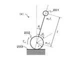
そして、以下の説明では、このような移動体本体141を、図2のようにモデル化する。
ここで、図2において、201は負荷、202は車輪、203は路面である。
図2に示すように移動体本体141は倒立して走行するものとする。
負荷201は、ロボットのボディや、移動体141に乗る人または荷物である。
車輪202は、負荷201を乗せ、回転することにより路面203との摩擦力を利用して移動する。In the following description, such a moving body
Here, in FIG. 2, 201 is a load, 202 is a wheel, and 203 is a road surface.
As shown in FIG. 2, it is assumed that the mobile body
The
The
状態センサ142は、負荷201の角度(θ1)と、車輪202の角度(θ2)を検出するものである。
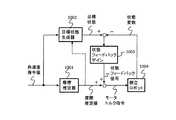
指令部100は、車輪水平速度指令生成器101と、負荷角度指令演算器102と、を備える。
車輪水平速度指令生成器101は、移動体本体141の車輪202の所望の水平移動速度である車輪水平速度指令を生成し出力する。
負荷角度指令演算器102は、車輪水平速度指令を入力とし、移動体本体141が走行する路面203が水平な場合に車輪水平速度が車輪水平速度指令に追従するような負荷角度である負荷角度指令を算出し出力する。The
The wheel horizontal
The load
制御装置110は、場合分け線形制御部120と、非線形制御部130と、トルク指令演算器111と、を備える。 The
場合分け線形制御部120は、減衰範囲演算器121と、減衰パラメータ演算器122と、場合分け線形トルク演算器123と、制御切替器124と、を備える。 The case-specific
減衰範囲演算器121には、負荷角度指令演算器102からの負荷角度指令と、状態センサ142による検出値である負荷角度θ1および車輪角度θ2と、が入力される。
減衰範囲演算器121は、入力信号に基づき、移動体本体141の動作制御において粘性摩擦を用いた減衰のみ加える負荷角度の範囲を減衰範囲として算出し出力する。The
Based on the input signal, the
減衰パラメータ演算器122には、負荷角度指令演算器102からの負荷角度指令(θ1*)と、状態センサ142による検出値である負荷角度(θ1)および車輪角度(θ2)と、が入力される。
減衰パラメータ演算器122は、入力信号に基づき、前記減衰範囲における制御に用いる減衰パラメータを算出し出力する。The
The
場合分け線形トルク演算器123には、負荷角度指令演算器102からの負荷角度指令(θ1*)と、減衰パラメータ演算器122からの減衰パラメータと、状態センサ142による検出値である負荷角度(θ1)および車輪角度(θ2)と、が入力される。
場合分け線形トルク演算器123は、負荷速度と減衰パラメータとの乗算値に負号を付した減衰トルクと、位置偏差、速度偏差および加速度偏差の一つ以上に所定ゲインを乗算して得る線形フィードバックトルクと、を算出して出力する。The case-dependent
The case-by-case
制御切替器124には、減衰範囲演算器121にて算出された減衰範囲と、状態センサ142による検出値と、場合分け線形トルク演算器123にて算出された場合分け線形トルクと、が入力されている。
制御切替器124は、場合分け線形トルク演算器123にて算出された場合分け線形トルクを切り替えて出力する。The
The
非線形制御部130は、車輪垂直加速度推定器131と、車輪水平速度推定器132と、非線形トルク演算器133と、を備える。
車輪垂直加速度推定器131には、状態センサ142からの検出信号が入力され、車輪垂直加速度推定器131は、その入力信号に基づいて車輪202の垂直加速度を推定し車輪垂直加速度推定値として出力する。
車輪水平速度推定器132には、状態センサ142からの検出信号が入力され、車輪水平速度推定器132は、その入力信号に基づいて車輪202の水平速度を推定し車輪水平速度推定値として出力する。
非線形トルク演算器133には、前記車輪垂直加速度推定値と前記車輪水平速度推定値とが入力され、非線形トルク演算器133は、移動体本体141の非線形ダイナミクスを示す非線形トルクを演算し出力する。The
A detection signal from the
The detection signal from the
The
トルク指令演算器111には、制御切替器124で切り替え出力される前記場合分け線形トルクと非線形トルク演算器133から出力される前記非線形トルクとが入力され、トルク指令演算器111は、これら入力信号の加算値を前記車輪202の半径で除算して得たトルク指令を出力する。 The
移動体本体141は前記トルク指令により駆動される。 The
以下、本第1実施形態に係る制御装置110が移動体本体141の動作を制御する仕組みの詳細を説明する。 Hereinafter, the details of the mechanism by which the
図2において、次のようにパラメータを設定する。
m1は負荷質量、
J1は負荷慣性モーメント、
m2は車輪質量、
J2は車輪慣性モーメント、
lは負荷と車輪の重心間距離である負荷車輪重心間距離、
rは車輪半径、
θ1は負荷角度、
θ2は車輪角度、
Trefはトルク指令、とする。
さらに、車輪水平位置をx2、車輪垂直位置をy2とすると、負荷水平位置x1および負荷垂直位置y1は次のようにそれぞれ式(1)と式(2)とであらわされる。In FIG. 2, parameters are set as follows.
m1 is the load mass,
J1 is the load moment of inertia,
m2 is the wheel mass,
J2 is the wheel moment of inertia,
l is the distance between the center of gravity of the load wheel and the center of gravity of the wheel,
r is the wheel radius,
θ1 is the load angle,
θ2 is the wheel angle,
Tref is a torque command.
Furthermore, when the wheel horizontal position is x2 and the wheel vertical position is y2 , the load horizontal position x1 and the load vertical position y1 are expressed by the following equations (1) and (2), respectively.

式(1)と式(2)とを用い、移動体本体141の運動エネルギーTおよびポテンシャルエネルギーVは次のようにそれぞれ式(3)と式(4)とであらわされる。 Using equations (1) and (2), the kinetic energy T and potential energy V of the moving
すると、オイラーラグランジュ方程式を用い、移動体本体141の運動方程式は式(5)乃至(8)と求められる。 Then, using the Euler-Lagrange equation, equations of motion of the moving
ただし、gは重力加速度である。
さらに、車輪202と路面203の間の粘性摩擦を考慮すると、式(6)と式(7)は式(9)と式(10)と書き換えられる。
ここに、Dは粘性摩擦係数とする。However, g is a gravitational acceleration.
Further, when the viscous friction between the
Here, D is a viscous friction coefficient.
式(9)と式(10)とを用い、式(11)が得られる。 Using Expression (9) and Expression (10), Expression (11) is obtained.
式(5)から式(11)を減算すると式(12)が得られる。 When Expression (11) is subtracted from Expression (5), Expression (12) is obtained.
ただし、Nxは車輪水平位置x2をパラメータとした非線形項、Nyは車輪垂直位置y2をパラメータとした非線形項である。However, Nx is a nonlinear term with the wheel horizontal position x2 as a parameter, and Ny is a nonlinear term with the wheel vertical position y2 as a parameter.
負荷角度θ1は車輪水平位置x2より十分に遅く変化すると仮定すると、式(11)は式(13)と書き換えられる。Assuming that the load angle θ1 changes sufficiently later than the wheel horizontal position x2 , Equation (11) can be rewritten as Equation (13).
ただし、車輪水平位置x2より十分に遅く変化する部分を定数c1、c2、c3とした。
式(13)より、車輪水平速度dx2/dtは式(14)であらわされる。However, to a portion which varies sufficiently slower than the wheel horizontal position x2 and constants c1, c2, c3.
From equation (13), the wheel horizontal speed dx2 / dt is expressed by equation (14).
ただし、s2・Θ2は車輪加速度(d2θ2/dt2)のラプラス変換、Lはラプラス演算子である。
車輪水平速度推定器132は式(14)を用いて前記車輪水平速度推定値を算出する。Here, s2 · Θ2 is a Laplace transform of wheel acceleration (d2 θ2 / dt2 ), and L is a Laplace operator.
The wheel
一方、式(8)を車輪垂直加速度(d2y2/dt2)について解くと式(15)が得られる。On the other hand, when equation (8) is solved for wheel vertical acceleration (d2 y2 / dt2 ), equation (15) is obtained.
車輪垂直加速度推定器131は、式(15)を用いて前記車輪垂直加速度推定値を算出する。 The wheel
所望の車輪水平速度である車輪水平速度指令をv2*(=x2*の一階微分)とすると、路面203が水平で平らな場合に車輪水平速度dx2/dtが前記車輪水平速度指令v2*となる負荷角度θ1である負荷角度指令θ1*は式(16)であらわされる。すなわち、負荷角度指令は、車輪水平加速度指令を重力加速度で除算した値の逆正接である。Assuming that the wheel horizontal speed command which is a desired wheel horizontal speed is v2* (= x2 * first order differential), the wheel horizontal speed dx2 / dt is the wheel horizontal speed command when the
車輪水平速度指令生成器101は、車輪水平速度指令v2*(=x2*の一階微分)を出力し、負荷角度指令演算器102は、式(16)を用いて負荷角度指令θ1*を算出し出力する。The wheel horizontal
式(14)と式(15)を式(12)に代入すると、式(17)が得られる。 Substituting Equation (14) and Equation (15) into Equation (12) yields Equation (17).
式(17)を書き換えると式(18)とあらわされる。 Rewriting equation (17) gives equation (18).
ただし、uは場合分け線形トルクである。
そして、負荷角度θ1が負荷角度指令θ1*に収束するような、式(19)に示す場合分け線形トルクuを考える。However, u is a case-by-case linear torque.
Then, as the load angle theta1 is converged to a load angle command theta1*, consider a linear torque u divided case shown in equation (19).
ただし、e=θ1*−θ1は、負荷角度追従偏差、
βは、速度比例制御ゲイン、
κは、位置比例制御ゲイン、
γは、減衰パラメータ、
sgn(・)は、・が正数のとき+1、負数のとき−1、零のとき0の値をとるシグナム関数である。Where e = θ1* −θ1 is the load angle tracking deviation,
β is the speed proportional control gain,
κ is the position proportional control gain,
γ is the attenuation parameter,
sgn (•) is a signum function that takes a value of +1 when • is a positive number, −1 when a negative number, and 0 when it is zero.
また、h=c|θ1*|は、フィードバック制御によるチャタリングを抑制するために設けた負荷角度範囲である減衰範囲であり、cは、減衰範囲hのパラメータである。Further, h = c | θ1* | is an attenuation range that is a load angle range provided to suppress chattering by feedback control, and c is a parameter of the attenuation range h.
ここで、式(19)に表される場合分け線形トルクuの意味は、負荷角度θ1と負荷角度指令θ1*との偏差が小さい場合、具体的には、負荷角度θ1の絶対値が減少する方向において負荷角度θ1と負荷角度指令θ1*との角度ずれが減衰範囲hの範囲内である場合、負荷201には粘性摩擦が減衰パラメータγである動作をさせることにより、負荷角度θ1を負荷角度指令θ1*に安定して収束させることができることを表す。
また、負荷角度θ1と負荷角度指令θ1*とのずれが上記以外の場合、負荷201には、剛性が位置比例制御ゲインκで、粘性摩擦が速度比例制御ゲインβであるフィードバック制御をかけることにより、負荷角度θ1を負荷角度指令θ1*に収束させることができることを表す。Here, the case-by-case linear torque u represented by the equation (19) means that when the deviation between the load angle θ1 and the load angle command θ1* is small, specifically, the absolute value of the load angle θ1 . When the angular deviation between the load angle θ1 and the load angle command θ1* is within the range of the attenuation range h in the direction in which the load decreases, the
When the deviation between the load angle θ1 and the load angle command θ1* is other than the above, the
ここで、減衰パラメータγを例えば式(20)に示すように負荷角度指令θ1*と負荷角度追従偏差eの関数として設定すると好適である。Here, it is preferable to set the attenuation parameter γ as a function of the load angle command θ1* and the load angle tracking deviation e, for example, as shown in the equation (20).
すなわち、場合分け線形制御部120が負荷角度指令演算器102から負荷角度指令θ1*を受けると、負荷角度指令θ1*は減衰範囲演算器121、減衰パラメータ演算器122および場合分け線形トルク演算器123に入力される。
そして、減衰範囲演算器121は、負荷角度指令θ1*とパラメータcとを用いて、h=c|θ1*|である減衰範囲を算出する。
この求められた減衰範囲hは制御切替器124に出力される。That is, when the case-specific
Then, the
The obtained attenuation range h is output to the
また、減衰パラメータ演算器122は、上記式(20)に従って減衰パラメータγを算出し、場合分け線形トルク演算器123に出力する。 Further, the
場合分け線形トルク演算器123は、減衰パラメータ演算器122から与えられる減衰パラメータγおよび予め設定された速度比例制御ゲインβ、位置比例制御ゲインκを用い、式(19)の場合分け線形トルクuを算出する。
算出した場合分け線形トルクuは、制御切替器124に出力する。The case-specific
The calculated case-specific linear torque u is output to the
制御切替器124は、場合分け線形トルク演算器123にて求められた場合分け線形トルクuを負荷角度追従偏差eおよび減衰範囲hを参照して切替選択する。
制御切替器124にて選択された場合分け線形トルクはトルク指令演算器111に出力される。The
The case-dependent linear torque selected by the
また、非線形トルク演算器133は、式(15)を用いて算出した車輪垂直加速度推定値と、式(14)を用いて算出した車輪水平速度推定値に基づいて、式(12)のNx+Nyである非線形トルクを算出し出力する。 Further, the
トルク指令演算器111は、場合分け線形トルクuと非線形トルクNx+Nyを用いて式(21)によりトルク指令Trefを算出し出力する。 The
ただし、rは車輪半径である。
移動体本体141はトルク指令Trefにより駆動制御される。Where r is the wheel radius.
The
このような構成を備える本第1実施形態によれば、次の効果を奏することができる。
(1)本第1実施形態では、式(19)に示すように、負荷角度θ1を3つの範囲に分け、それぞれの場合に最適なトルク指令を算出する。
そして、制御切替器124において減衰範囲の内と外とで制御を切り替える。
これにより、負荷角度θ1が負荷角度指令θ1*の近傍において振動することなく、負荷角度指令θ1*に滑らかに収束するようにすることができる。
その結果、安定した水平走行を実現させることができる。According to the first embodiment having such a configuration, the following effects can be achieved.
(1) In the first embodiment, as shown in Expression (19), the load angle θ1 is divided into three ranges, and an optimum torque command is calculated in each case.
Then, the
Thus, without the load angle theta1 is vibrated in the vicinity of the load angle command theta1*, can be made to smoothly converge the load angle command theta1*.
As a result, stable horizontal travel can be realized.
(2)減衰パラメータ演算器122を備え、式(20)により減衰パラメータγを設定するので、減衰パラメータγを一定値に固定する場合に比べ、滑らかに速く負荷角度θ1を負荷角度指令θ1*に収束させることができる。(2) comprising a damping
(3) 式(14)の車輪水平速度推定値を用いて移動体本体141を制御するので、車輪202と路面203が相対的にすべる場合にも移動体本体141の車輪水平速度v2(=x2の一階微分)を車輪水平速度指令v2*(x2*の一階微分)に一致させることができる。(3) Since the moving body
(4) 式(15)の車輪垂直加速度推定値を用いて移動体本体141を制御するので、路面203に凹凸があっても車輪202が路面203に接触している間は負荷角度θ1を安定に制御することができる。(4) Since the moving body
(実験例)
次に、本発明の効果を実証する実験例を示す。
実験例として、第1実施形態のシミュレーション結果を示す。
ここで、シミュレーションに用いた数値は以下のとおりである。(Experimental example)
Next, experimental examples demonstrating the effects of the present invention will be shown.
As an experimental example, the simulation result of the first embodiment is shown.
Here, the numerical values used in the simulation are as follows.
m1=70 [kg]、
J1= 25.2 [kg・m2]、
m2= 15 [kg]、
J2= 0.075 [kg・m2]、
l = 0.9 [m]、
r = 0.1 [m]、
D = 0.1 [N・s/m]、
g = 9.8 [m/s2]、
T = 1×10⁻³ [s]、
κ = 40 [s-1]、
J10= m1×l2+J1 [kg・m2]、
β0= 2πκ [s-1]、
β = β0×J10 [N・m・s/rad]、
γ = 0.1 [N・m・s/rad]、
pcl = [-49.9、-201.4] [rad/s]、
td = 0.5 [s]m1 = 70 [kg],
J1 = 25.2 [kg · m2 ],
m2 = 15 [kg],
J2 = 0.075 [kg ・ m2 ],
l = 0.9 [m],
r = 0.1 [m],
D = 0.1 [N · s / m],
g = 9.8 [m / s2 ],
T = 1 × 10⁻³ [s],
κ = 40 [s-1 ],
J10 = m1 × l2 + J1 [kg · m2 ],
β0 = 2πκ [s-1 ],
β = β0 × J10 [N · m · s / rad],
γ = 0.1 [N · m · s / rad],
pcl = [-49.9, -201.4] [rad / s],
td = 0.5 [s]
ただし、
m1は負荷質量、
J1は、負荷慣性モーメント、
m2は、車輪質量、
J2は、車輪慣性モーメント、
lは、負荷車輪重心間距離、
rは、車輪半径、
Dは、車輪路面間粘性摩擦、
gは、重力加速度、
Tは、制御周期、
κは、本発明における位置比例制御ゲイン、
J10は、公称慣性モーメント、
β0は、本発明における正規化速度比例制御ゲイン、
βは、本発明における速度比例制御ゲイン、
γは、本発明における摩擦パラメータ、
pclは、従来技術における閉ループ極、
tdは、インパルス外乱時間、である。However,
m1 is the load mass,
J1 is the load moment of inertia,
m2 is the wheel mass,
J2 is the wheel moment of inertia,
l is the load wheel center of gravity distance,
r is the wheel radius,
D is the viscous friction between wheel surfaces,
g is the acceleration of gravity,
T is the control cycle,
κ is a position proportional control gain in the present invention,
J10 is the nominal moment of inertia,
β0 is a normalized speed proportional control gain in the present invention,
β is a speed proportional control gain in the present invention,
γ is a friction parameter in the present invention,
pcl is a closed loop pole in the prior art,
td is an impulse disturbance time.
なお、
車輪路面間粘性摩擦Dは、図2の車輪202と路面203の間にはたらく粘性摩擦であり、
公称慣性モーメントJ10は、本発明における速度ループを正規化するパラメータであり、
pclは、従来技術における状態フィードバック制御で配置する閉ループの極、である。
また、インパルス外乱時間tdにおいて、車輪202の鉛直上方方向にインパルス状の加速度外乱入力がある場合を考える。In addition,
The viscous friction D between wheel road surfaces is a viscous friction acting between the
The nominal moment of inertia J10 is a parameter that normalizes the speed loop in the present invention,
pcl is a closed-loop pole disposed by state feedback control in the prior art.
Further, consider a case where there is an impulse-like acceleration disturbance input in the vertically upward direction of the
図3、図4はシミュレーション結果を示す図である。
図3は、負荷角度の変化を示す。
図3において、破線L11は負荷角度指令(Load angular position reference input)、実線L10は本発明による負荷角度(Load angular position with proposed control)、一点鎖線L12は従来技術による負荷角度を示す。
加速度外乱を入力する0.5[s]までは、従来技術と本発明とは共に負荷角度指令にほぼ同じ程度に追従しているが、0.5[s]以降は従来技術では負荷角度が発振しているのに対し、本発明では前記加速度外乱入力後も発振することなく前記負荷角度指令に追従していることが分かる。3 and 4 are diagrams showing simulation results.
FIG. 3 shows changes in the load angle.
3, a broken line L11 is the load angle command (Load angular position reference input), the solid line L10 is the load angle by the present invention (Load angular position with proposed control) , one-dot chain line L12 represents the load angle of the prior art.
Up to 0.5 [s] when the acceleration disturbance is input, both the conventional technology and the present invention follow the load angle command to the same extent. However, after 0.5 [s], the load angle oscillates in the conventional technology. On the other hand, it can be seen that the present invention follows the load angle command without oscillating even after the acceleration disturbance input.
そして、本発明による負荷角度が折れ線状の時間変化をしているのは、式(19)の前記減衰範囲において減衰のみを加える制御を実施しているためであり、前記減衰範囲をもたせることにより前記負荷位置が前記負荷位置指令の近傍において振動的になりにくくなっていることが示された。 The reason why the load angle according to the present invention changes in a polygonal time is because control is performed to add only attenuation in the attenuation range of Equation (19), and by providing the attenuation range, It was shown that the load position is less likely to vibrate in the vicinity of the load position command.
また、車輪垂直加速度推定器131において、式(15)の車輪垂直加速度推定値を算出し、非線形トルク演算器133において、非線形トルクNyを算出することにより、路面203の凹凸のため車輪202に加わる垂直方向の前記加速度外乱を補償できるので、本発明は前記加速度外乱が存在する場合にも前記負荷角度を安定化させることが示された。 Further, the wheel
図4は、車輪の水平速度変化を示す。
図4において、破線L21は所望の車輪水平速度、実線L20は本発明による車輪水平速度、一点鎖線L22は従来技術による車輪水平速度である。
加速度外乱を入力する0.5[s]までは従来技術も本発明も共に前記所望の車輪水平速度に追従しているが、0.5[s]以降において従来技術は振動的となるのに対し、本発明は振動的とならず前記所望の車輪水平速度に追従していることがわかる。FIG. 4 shows the change in the horizontal speed of the wheel.
In FIG. 4, a broken line L21 is a desired wheel horizontal speed, a solid line L20 is a wheel horizontal speed according to the present invention, and a one-dot chain line L22 is a wheel horizontal speed according to the prior art.
Both the prior art and the present invention follow the desired wheel horizontal speed up to 0.5 [s] when the acceleration disturbance is input, whereas the prior art becomes vibrational after 0.5 [s]. It can be seen that does not vibrate and follows the desired wheel horizontal speed.
(変形例1)
上記第1実施形態においては、減衰パラメータγは、上記式(20)に従って減衰パラメータ演算器122により算出したものを用いたが、減衰パラメータγは予め設定された固定値としてもよい。
すなわち、図5に示すように、予め設定された減衰パラメータを減衰パラメータ記憶部125に設定記憶させておき、減衰パラメータ記憶部125から場合分け線形トルク演算器123に減衰パラメータγの値を供給するようにしてもよい。(Modification 1)
In the first embodiment, the attenuation parameter γ calculated by the
That is, as shown in FIG. 5, a preset attenuation parameter is set and stored in the attenuation
(変形例2)
また、上記第1実施形態では、最も好適な実施形態として非線形制御部130を有する場合を説明したが、負荷角度指令θ1*の近傍において振動することなく負荷角度θ1を負荷角度指令θ1*に滑らかに収束させる安定した制御を実現させる場合、非線形制御部130は無くてもよい。
すなわち、図6に示すように、非線形制御部130を省略した制御装置610であってもよい。(Modification 2)
In the first embodiment, a case has been described with a
That is, as shown in FIG. 6, a
ここで、非線形制御部130を省略して場合分け線形制御部120だけを備える場合には、場合分け線形トルク演算器123にて算出する場合分け線形トルクuの線形フィードバックトルクのゲインを調整して、外乱となる非線形要素をできる限り抑え込むようなゲインを設定することが好まししい。 Here, when the
ただし、水平ではない凹凸路面の走行や障害物との衝突、車輪の空転などの非線形要素に対応するためには非線形制御部130を合わせもっていた方がよいことはもちろんである。 However, it goes without saying that the
なお、本発明は上記実施形態に限定されず、本発明の目的を達成できる範囲での変形、改良等は本発明に含まれる。
例えば、式(19)において、位置P/速度P制御は、位置P/速度PI制御、位置P/速度I−P制御、位置PID制御など、任意の制御則に置き換えても良いことはもちろんである。In addition, this invention is not limited to the said embodiment, The deformation | transformation in the range which can achieve the objective of this invention, improvement, etc. are included in this invention.
For example, in the equation (19), the position P / speed P control may be replaced with an arbitrary control law such as position P / speed PI control, position P / speed IP control, position PID control, etc. is there.
本発明は、路面に凹凸がある場合にも、人や物体と衝突した場合にも、転倒することなく、発振することなく2輪倒立の移動体を所望の水平速度で走行させることができるので、2輪倒立で走行するロボット、電動車椅子、自動搬送装置、災害時の人命救助など狭い場所で作業するロボット、振動に弱い電子部品の組み立て装置などに広く適用できる。The present invention can move a two-wheel inverted moving body at a desired horizontal speed without tipping over and oscillating, even when the road surface is uneven or collides with a person or an object. It can be widely applied to robots that run with two wheels inverted, electric wheelchairs, automatic transfer devices, robots that work in narrow places such as lifesaving in disasters, and assembly devices for electronic components that are vulnerable to vibration.
100…指令部、101…車輪水平速度指令生成器、102…負荷角度指令演算器、111…トルク指令演算器、120…場合分け線形制御部、121…減衰範囲演算器、122…減衰パラメータ演算器、123…場合分け線形トルク演算器、124…制御切替器、130…非線形制御部、131…車輪垂直加速度推定器、132…車輪水平速度推定器、133…非線形トルク演算器、141…移動体本体、142…状態センサ、125…減衰パラメータ記憶部、110、610…制御装置、201…負荷、202…車輪、203…路面、1001…摩擦推定器、1002…目標状態生成器、1003…状態フィードバックゲイン、1004…倒立ロボット。DESCRIPTION OF
Claims (8)
Translated fromJapanese前記負荷の重心と前記車輪の重心とをつなぐ直線が鉛直線との間になす角を負荷角度とし、
車輪水平速度指令に基づいて求められる負荷角度指令を入力として、前記負荷角度指令から前記負荷角度を減算した値である負荷角度追従偏差に基づく線形フィードバックトルクを前記移動体本体に加えるように制御し、
前記負荷角度が前記負荷角度指令の近傍の幅としての減衰範囲内である場合、前記線形フィードバックトルクを加えないで、減衰トルクを前記移動体本体に加えるように制御する
ことを特徴とする倒立型移動体の制御装置。A control device that performs traveling control while inverting a moving body having a driving means having wheels and a load that is inverted and controlled on the wheels via a link,
The angle formed between the vertical line and the straight line connecting the center of gravity of the load and the center of gravity of the wheel is the load angle,
Control is performed so that a linear feedback torque based on a load angle follow-up deviation, which is a value obtained by subtracting the load angle from the load angle command, is applied to the movable body body, with a load angle command obtained based on a wheel horizontal speed command as an input. ,
If the load angleiswithin the damping range of the width in the vicinity ofthe load angle command,without adding the linear feedback torque, and controls so asto applyattenuated torque to said mobile body Inverted moving body control device.
前記減衰範囲は、前記負荷角度指令の絶対値に所定の係数を乗算して算出する
ことを特徴とする倒立型移動体の制御装置。In the control device for an inverted moving body according to claim 1,
BeforeSL Attenuation range, the load angle command inverted vehicle control apparatus characterized by calculating by multiplying a predetermined coefficient to the absolute value of.
前記減衰トルクを粘性摩擦とする
ことを特徴とする倒立型移動体の制御装置。In the control device for an inverted moving body according to claim 1 or 2,
The control apparatus for an inverted moving body, wherein the dampingtorque is viscous friction.
前記負荷角度追従偏差と、前記負荷角度指令と、の関数として前記粘性摩擦である減衰パラメータを算出する
ことを特徴とする倒立型移動体の制御装置。In the control device for an inverted moving body according to claim 3,
Before andKimake load angle tracking error, the load angle command and, inverted vehicle control apparatus characterized by calculating a damping parameter is the viscous friction as a function of.
前記負荷角度指令の絶対値を2で除算した値を前記負荷角度追従偏差から減算し、その絶対値を前記負荷角度指令の絶対値で除算し、さらに定数を乗算することによって前記減衰パラメータを算出する
ことを特徴とする倒立型移動体の制御装置。In the control device for an inverted moving body according to claim 4,
The attenuation parameter is calculated by subtracting the value obtained by dividing the absolute value of the load angle command by 2 from the load angle tracking deviation, dividing the absolute value by the absolute value of the load angle command, and further multiplying by a constant. An inverted moving body control device characterized by:
前記粘性摩擦である減衰パラメータを一定値とする
ことを特徴とする倒立型移動体の制御装置。In the control device for an inverted moving body according to claim 3,
A control apparatus for an inverted moving body, wherein the damping parameter, which is the viscous friction, is set to a constant value.
前記負荷速度と前記減衰パラメータとの乗算値に負号を付した減衰トルクと、前記負荷角度追従偏差に基づく線形フィードバックトルクと、を算出する場合分け線形トルク演算器と、
前記場合分け線形トルク演算器で算出された前記減衰トルクと前記線形フィードバックトルクとを切り替えて出力する制御切替器と、を備える
ことを特徴とする倒立型移動体の制御装置。In the control device for an inverted moving body according to any one of claims 4 to 6,
A linear torque unit divided when calculating the attenuation torque denoted by the minus sign multiplication value of the load speed and the damping parameter, thelinear feedback torquebased on the load angle tracking error, and
A control switch for switching the damping torque calculated by the case-by-case linear torque calculator and the linear feedback torque and outputting the switching torque.
前記制御切替器は、
0 ≦ sgn(θ1*)・e < h
の場合には、前記減衰トルクを出力し、
それ以外の場合には前記線形フィードバックトルクを出力することを特徴とする倒立型移動体の制御装置。
ただし、e=θ1*−θ1であり、θ1*は負荷角度指令であり、θ1は負荷角度であり、sgn(・)は、・が正数のとき+1、負数のとき−1、零のとき0の値をとるシグナム関数であり、hは前記負荷角度指令の絶対値に所定の係数を乗算して算出する減衰範囲である。In the control device for an inverted moving body according to claim 7,
The control switch is
0 ≤ sgn (θ1* ) · e <h
In this case, the damping torque is output,
In other cases, the control apparatus for an inverted moving body is characterized by outputting the linear feedback torque.
However, e = θ1* −θ1 , θ1* is a load angle command, θ1 is a load angle, and sgn (•) is +1 when • is a positive number and −1 when it is a negative number , A signum function that takes a value of 0 when zero, and h is an attenuation range calculated by multiplying the absolute value of the load angle command by a predetermined coefficient.
Priority Applications (5)
| Application Number | Priority Date | Filing Date | Title |
|---|---|---|---|
| JP2009109591AJP5093185B2 (en) | 2009-04-28 | 2009-04-28 | Inverted moving body control device |
| US12/993,194US8612127B2 (en) | 2009-04-28 | 2010-02-26 | Inverted vehicle |
| EP10769429.1AEP2426566B1 (en) | 2009-04-28 | 2010-02-26 | Control portion for inverted vehicle |
| PCT/JP2010/001309WO2010125727A1 (en) | 2009-04-28 | 2010-02-26 | Control portion for inverted vehicle |
| CN2010800176070ACN102405449B (en) | 2009-04-28 | 2010-02-26 | Control device for inverted vehicle |
Applications Claiming Priority (1)
| Application Number | Priority Date | Filing Date | Title |
|---|---|---|---|
| JP2009109591AJP5093185B2 (en) | 2009-04-28 | 2009-04-28 | Inverted moving body control device |
Publications (2)
| Publication Number | Publication Date |
|---|---|
| JP2010257399A JP2010257399A (en) | 2010-11-11 |
| JP5093185B2true JP5093185B2 (en) | 2012-12-05 |
Family
ID=43031887
Family Applications (1)
| Application Number | Title | Priority Date | Filing Date |
|---|---|---|---|
| JP2009109591AExpired - Fee RelatedJP5093185B2 (en) | 2009-04-28 | 2009-04-28 | Inverted moving body control device |
Country Status (5)
| Country | Link |
|---|---|
| US (1) | US8612127B2 (en) |
| EP (1) | EP2426566B1 (en) |
| JP (1) | JP5093185B2 (en) |
| CN (1) | CN102405449B (en) |
| WO (1) | WO2010125727A1 (en) |
Families Citing this family (5)
| Publication number | Priority date | Publication date | Assignee | Title |
|---|---|---|---|---|
| FR2969571B1 (en)* | 2010-12-23 | 2015-01-16 | Thales Sa | ROBOTIC SYSTEM COLLABORATOR |
| JP6544851B2 (en)* | 2015-03-31 | 2019-07-17 | Dmg森精機株式会社 | Patent application title: Parameter setting method for positioning device, parameter setting device, and positioning device provided with the parameter setting device |
| CN106371434B (en)* | 2015-07-23 | 2020-06-23 | 联想(北京)有限公司 | Method for controlling mobile device to keep balance and mobile device |
| CN105667661B (en)* | 2016-01-29 | 2018-04-20 | 何武 | Electrodynamic balance car and its repositioning method |
| US10350754B2 (en)* | 2016-09-27 | 2019-07-16 | Denso Wave Incorporated | Control device for robot |
Family Cites Families (16)
| Publication number | Priority date | Publication date | Assignee | Title |
|---|---|---|---|---|
| US5455497A (en)* | 1992-04-20 | 1995-10-03 | Honda Giken Kogyo Kabushiki Kaisha | Legged mobile robot and a system for controlling the same |
| JP3148827B2 (en)* | 1992-04-30 | 2001-03-26 | 本田技研工業株式会社 | Walking control device for legged mobile robot |
| US7370713B1 (en)* | 1993-02-24 | 2008-05-13 | Deka Products Limited Partnership | Personal mobility vehicles and methods |
| AU771830B2 (en)* | 1999-03-15 | 2004-04-01 | Deka Products Limited Partnership | Control of a balancing personal vehicle |
| JP3888295B2 (en)* | 2002-11-26 | 2007-02-28 | トヨタ自動車株式会社 | Walking robot that lowers the gain of inverted pendulum control when stationary |
| US7366587B2 (en)* | 2002-12-05 | 2008-04-29 | Sony Corporation | Legged mobile robot |
| WO2005016735A1 (en)* | 2003-08-18 | 2005-02-24 | Canterprise Limited | A powered unicycle |
| JP2006123014A (en) | 2004-10-26 | 2006-05-18 | Matsushita Electric Ind Co Ltd | Inverted two-wheeled robot |
| JP4646640B2 (en)* | 2005-01-26 | 2011-03-09 | 株式会社豊田中央研究所 | Mobile cart and control method of mobile cart |
| JP4650327B2 (en) | 2005-04-14 | 2011-03-16 | トヨタ自動車株式会社 | Coaxial motorcycle |
| JP4760162B2 (en)* | 2005-06-29 | 2011-08-31 | トヨタ自動車株式会社 | Control method of mobile cart and mobile cart |
| EP2017172A4 (en)* | 2006-05-09 | 2011-11-02 | Equos Res Co Ltd | VEHICLE, CHARACTERISTIC VALUE ESTIMATING DEVICE AND DEVICE FOR DETERMINING A LOADED ARTICLE |
| JP4418905B2 (en)* | 2007-05-02 | 2010-02-24 | 株式会社国際電気通信基礎技術研究所 | Communication robot |
| JP5088061B2 (en)* | 2007-09-19 | 2012-12-05 | 株式会社エクォス・リサーチ | vehicle |
| JP5065853B2 (en) | 2007-10-26 | 2012-11-07 | 旭化成イーマテリアルズ株式会社 | Photosensitive polyamic acid composition and photosensitive dry film |
| US20110313568A1 (en)* | 2009-01-07 | 2011-12-22 | Trevor Blackwell | Robot Including Electrically Activated Joints |
- 2009
- 2009-04-28JPJP2009109591Apatent/JP5093185B2/ennot_activeExpired - Fee Related
- 2010
- 2010-02-26EPEP10769429.1Apatent/EP2426566B1/ennot_activeNot-in-force
- 2010-02-26WOPCT/JP2010/001309patent/WO2010125727A1/ennot_activeCeased
- 2010-02-26CNCN2010800176070Apatent/CN102405449B/ennot_activeExpired - Fee Related
- 2010-02-26USUS12/993,194patent/US8612127B2/enactiveActive
Also Published As
| Publication number | Publication date |
|---|---|
| EP2426566A4 (en) | 2015-04-29 |
| US20110071728A1 (en) | 2011-03-24 |
| WO2010125727A1 (en) | 2010-11-04 |
| US8612127B2 (en) | 2013-12-17 |
| CN102405449B (en) | 2013-08-21 |
| EP2426566B1 (en) | 2016-08-31 |
| CN102405449A (en) | 2012-04-04 |
| EP2426566A1 (en) | 2012-03-07 |
| JP2010257399A (en) | 2010-11-11 |
Similar Documents
| Publication | Publication Date | Title |
|---|---|---|
| JP4434186B2 (en) | MOBILE BODY AND METHOD FOR CONTROLLING MOBILE BODY | |
| JP3993883B2 (en) | Inverted two-wheeled traveling robot and control method thereof | |
| Chan et al. | Review of modelling and control of two-wheeled robots | |
| Ooi | Balancing a two-wheeled autonomous robot | |
| JP4600539B2 (en) | TRAVEL DEVICE AND TRAVEL DEVICE CONTROL METHOD | |
| US8738259B2 (en) | Movable body, travel device, and movable body control method | |
| JP5093185B2 (en) | Inverted moving body control device | |
| JP5761347B2 (en) | Inverted moving body control device, control method thereof, and program | |
| WO2007069401A1 (en) | Gait creation device of leg-type mobile robot | |
| Mohammadi et al. | Model predictive motion control of autonomous forklift vehicles with dynamics balance constraint | |
| Prakash et al. | Study of controllers for a two wheeled self-balancing robot | |
| Raza et al. | Towards robust wheel-legged biped robot system: Combining feedforward and feedback control | |
| Lafaye et al. | Model predictive control for tilt recovery of an omnidirectional wheeled humanoid robot | |
| Hirata et al. | A realization of step passage motion in two-wheel wheelchair systems utilizing variable repulsive compliance control | |
| Jun et al. | A trajectory tracking control design for a skid-steering mobile robot by adapting its desired instantaneous center of rotation | |
| Li et al. | Controller design of a two-wheeled inverted pendulum mobile robot | |
| JP5169989B2 (en) | Inverted moving body control device | |
| Tsai et al. | Adaptive nonlinear control using RBFNN for an electric unicycle | |
| JP5316336B2 (en) | Inverted type moving body, its control method and control program | |
| Widyotriatmo | Comparative study of stabilization controls of a forklift vehicle | |
| Oh et al. | Control developments for wheelchairs in slope environments | |
| JP6221539B2 (en) | Wheel type moving body | |
| Kanazawa et al. | Model-Based Pitch Angle Compensation for Center of Gravity Variation in Underactuated System with an Arm | |
| Li et al. | Fuzzy logic self-motion planning and robust adaptive control for tip-over avoidance of redundant mobile modular manipulators | |
| JP5652043B2 (en) | Inverted type moving body, its control method and control program |
Legal Events
| Date | Code | Title | Description |
|---|---|---|---|
| A131 | Notification of reasons for refusal | Free format text:JAPANESE INTERMEDIATE CODE: A131 Effective date:20120214 | |
| A521 | Request for written amendment filed | Free format text:JAPANESE INTERMEDIATE CODE: A523 Effective date:20120412 | |
| TRDD | Decision of grant or rejection written | ||
| A01 | Written decision to grant a patent or to grant a registration (utility model) | Free format text:JAPANESE INTERMEDIATE CODE: A01 Effective date:20120821 | |
| A01 | Written decision to grant a patent or to grant a registration (utility model) | Free format text:JAPANESE INTERMEDIATE CODE: A01 | |
| A61 | First payment of annual fees (during grant procedure) | Free format text:JAPANESE INTERMEDIATE CODE: A61 Effective date:20120903 | |
| R151 | Written notification of patent or utility model registration | Ref document number:5093185 Country of ref document:JP Free format text:JAPANESE INTERMEDIATE CODE: R151 | |
| FPAY | Renewal fee payment (event date is renewal date of database) | Free format text:PAYMENT UNTIL: 20150928 Year of fee payment:3 | |
| LAPS | Cancellation because of no payment of annual fees |