JP5093165B2 - Structure manufacturing method and structure - Google Patents
Structure manufacturing method and structureDownload PDFInfo
- Publication number
- JP5093165B2 JP5093165B2JP2009065051AJP2009065051AJP5093165B2JP 5093165 B2JP5093165 B2JP 5093165B2JP 2009065051 AJP2009065051 AJP 2009065051AJP 2009065051 AJP2009065051 AJP 2009065051AJP 5093165 B2JP5093165 B2JP 5093165B2
- Authority
- JP
- Japan
- Prior art keywords
- fabric
- shape
- mandrel
- stationary blade
- ceramic
- Prior art date
- Legal status (The legal status is an assumption and is not a legal conclusion. Google has not performed a legal analysis and makes no representation as to the accuracy of the status listed.)
- Active
Links
- 238000004519manufacturing processMethods0.000titleclaimsdescription23
- 239000004744fabricSubstances0.000claimsdescription83
- 239000000835fiberSubstances0.000claimsdescription45
- 238000000034methodMethods0.000claimsdescription41
- 239000002759woven fabricSubstances0.000claimsdescription35
- 239000000919ceramicSubstances0.000claimsdescription27
- 239000000463materialSubstances0.000claimsdescription20
- 239000011153ceramic matrix compositeSubstances0.000claimsdescription17
- 239000011159matrix materialSubstances0.000claimsdescription15
- 238000009954braidingMethods0.000claimsdescription7
- 238000005470impregnationMethods0.000description11
- 239000004753textileSubstances0.000description9
- 238000004804windingMethods0.000description6
- 238000009730filament windingMethods0.000description5
- 230000004048modificationEffects0.000description4
- 238000012986modificationMethods0.000description4
- 239000002184metalSubstances0.000description3
- 229910052751metalInorganic materials0.000description3
- 230000015572biosynthetic processEffects0.000description2
- 239000007789gasSubstances0.000description2
- VNWKTOKETHGBQD-UHFFFAOYSA-NmethaneChemical compoundCVNWKTOKETHGBQD-UHFFFAOYSA-N0.000description2
- HBMJWWWQQXIZIP-UHFFFAOYSA-Nsilicon carbideChemical compound[Si+]#[C-]HBMJWWWQQXIZIP-UHFFFAOYSA-N0.000description2
- 229910010271silicon carbideInorganic materials0.000description2
- 238000011282treatmentMethods0.000description2
- 229910052582BNInorganic materials0.000description1
- PZNSFCLAULLKQX-UHFFFAOYSA-NBoron nitrideChemical compoundN#BPZNSFCLAULLKQX-UHFFFAOYSA-N0.000description1
- OKTJSMMVPCPJKN-UHFFFAOYSA-NCarbonChemical compound[C]OKTJSMMVPCPJKN-UHFFFAOYSA-N0.000description1
- 229910052799carbonInorganic materials0.000description1
- 238000002485combustion reactionMethods0.000description1
- 239000002131composite materialSubstances0.000description1
- 239000000470constituentSubstances0.000description1
- 238000001816coolingMethods0.000description1
- 239000000112cooling gasSubstances0.000description1
- 239000003814drugSubstances0.000description1
- 238000009986fabric formationMethods0.000description1
- 239000007791liquid phaseSubstances0.000description1
- 150000002739metalsChemical class0.000description1
- 230000002093peripheral effectEffects0.000description1
- 239000002994raw materialSubstances0.000description1
- 230000000452restraining effectEffects0.000description1
- 239000007790solid phaseSubstances0.000description1
- 239000000126substanceSubstances0.000description1
- 238000005979thermal decomposition reactionMethods0.000description1
- 230000001131transforming effectEffects0.000description1
- 239000012808vapor phaseSubstances0.000description1
Images


Landscapes
- Turbine Rotor Nozzle Sealing (AREA)
- Producing Shaped Articles From Materials (AREA)
- Woven Fabrics (AREA)
Description
Translated fromJapanese本発明は、開口部を介して外部に接続される中空領域を備えると共にセラミックス基複合材料によって形成される構造物及びその製造方法に関するものである。 The present invention relates to a structure including a hollow region connected to the outside through an opening and formed of a ceramic matrix composite material and a method for manufacturing the structure.
近年は、構造物の形成材料として、金属にかえて耐熱性の優れたセラミックス基複合材料が用いられる場合がある。
このようなセラミックス基複合材料は、セラミックからなる繊維によって形成された織物に、セラミックからなるマトリックスが付着形成された材料であり、金属よりも優れた耐熱性を有している。In recent years, ceramic-based composite materials having excellent heat resistance in place of metals may be used as materials for forming structures.
Such a ceramic matrix composite material is a material in which a matrix made of ceramic is attached to a fabric made of fibers made of ceramic, and has heat resistance superior to that of metal.
このようなセラミックス基複合材料によって内部に中空領域を備えるタービン翼や燃焼室等の構造物を製造する場合には、例えば、上記中空領域の形状に成型されたマンドレル周りにセラミックからなる繊維を巻きつけて構造物の形状とされた織物を形成し、当該織物にマトリックスを付着形成する。 When manufacturing a structure such as a turbine blade or a combustion chamber having a hollow region inside using such a ceramic matrix composite material, for example, a fiber made of ceramic is wound around a mandrel formed in the shape of the hollow region. To form a fabric in the shape of a structure, and a matrix is deposited on the fabric.
ところで、構造物の中空領域の形状に成型されたマンドレル周りに繊維を巻き付ける方法としては、いわゆるブレイディング法やフィラメントワインディング法が知られている。
ブレイディング法は、マンドレルの延在方向に延びる中央糸とマンドレルに対して螺旋状に巻き付けられる複数の組糸とを編み込んでいく方法であり、複数の繊維が同時にマンドレルに対して巻き付けられる方法である。
一方、フィラメントワインディング法は、一本の繊維をマンドレル周りに巻き付ける方法である。By the way, as a method of winding a fiber around a mandrel formed in the shape of a hollow region of a structure, a so-called braiding method and a filament winding method are known.
The braiding method is a method in which a central yarn extending in the extending direction of the mandrel and a plurality of braids wound spirally around the mandrel are knitted, and a plurality of fibers are simultaneously wound around the mandrel. is there.
On the other hand, the filament winding method is a method of winding a single fiber around a mandrel.
しかしながら、実際の構造物は複雑な形状を有していることが一般的である。このため、構造物の中空領域の形状に成型されたマンドレルは複雑な形状であることが多い。
このような複雑な形状のマンドレルに対して繊維を巻き付けた場合には、マンドレルの形状に沿って繊維の一部が移動し、織物において繊維の偏りが発生する。
セラミックス基複合材料によって形成された構造物の強度は、繊維の密度や繊維の方向に依存する。このため、繊維の偏りが存在する場合には、構造物の強度が不均一となり、場所によって強度が変化する可能性がある。However, an actual structure generally has a complicated shape. For this reason, the mandrel molded into the shape of the hollow region of the structure often has a complicated shape.
When a fiber is wound around a mandrel having such a complicated shape, a part of the fiber moves along the shape of the mandrel, and the fiber is biased in the woven fabric.
The strength of the structure formed of the ceramic matrix composite material depends on the fiber density and fiber direction. For this reason, when there is a fiber bias, the strength of the structure becomes non-uniform, and the strength may change depending on the location.
本発明は、上述する問題点に鑑みてなされたもので、セラミックス基複合材料によって形成される構造物の強度を均一化させて構造物の品質を向上させることを目的とする。 The present invention has been made in view of the above-described problems, and an object thereof is to improve the quality of a structure by making the strength of the structure formed of a ceramic matrix composite material uniform.
本発明は、上記課題を解決するための手段として、以下の構成を採用する。 The present invention adopts the following configuration as means for solving the above-described problems.
第1の発明は、開口部を介して外部に接続される中空領域を備えると共にセラミックス基複合材料によって形成される構造物の製造方法であって、長さ方向における断面形状が中心軸を中心とする同心円形状とされたマンドレル周りにセラミックからなる繊維を巻き付けることによって、長さ方向における断面形状が中心軸を中心とする中空の同心円形状とされた織物を形成する織物形成工程と、該織物形成工程において形成された上記織物を上記構造物の形状に変形させた状態で、上記織物にセラミックを含浸させてマトリックスを形成するマトリックス形成工程とを有するという構成を採用する。 1st invention is a manufacturing method of the structure provided with the hollow area | region connected outside via an opening part, and is formed with a ceramic matrix composite material, Comprising: The cross-sectional shape in a length direction is centering on a central axis Forming a woven fabric in which a cross-sectional shape in the lengthwise direction is formed into a hollow concentric shape centering on the central axis by winding a fiber made of ceramic around a concentric circular mandrel, and forming the woven fabric A configuration is adopted in which the woven fabric formed in the step is deformed into the shape of the structure, and the matrix is formed by impregnating the woven fabric with ceramic to form a matrix.
第2の発明は、上記第1の発明において、上記マンドレルの長さ方向における各領域での周長が上記構造物の上記中空領域の長さ方向における各領域での周長と一致されているという構成を採用する。 According to a second invention, in the first invention, the circumference in each region in the length direction of the mandrel is matched with the circumference in each region in the length direction of the hollow region of the structure. The configuration is adopted.
第3の発明は、上記第1または第2の発明において、上記マンドレルが、上記繊維が巻き付けられた状態で取り外しまたは消失可能とされているという構成を採用する。 According to a third invention, in the first or second invention, a configuration is adopted in which the mandrel is removable or disappearable in a state where the fiber is wound.
第4の発明は、上記第1〜第3いずれかの発明において、上記マトリックス形成工程において、上記構造物の中空領域の形状に成型された内型と上記構造物の外形形状に成型された外型とによって挟み込むことによって上記織物を上記構造物の形状に変形させるという構成を採用する。 According to a fourth invention, in any one of the first to third inventions, in the matrix formation step, an inner mold molded into the shape of the hollow region of the structure and an outer shape molded into the outer shape of the structure A configuration is adopted in which the fabric is deformed into the shape of the structure by being sandwiched by a mold.
第5の発明は、上記第4の発明において、上記内型が、上記構造物の上記中空領域において取り外しまたは消失可能とされているという構成を採用する。 A fifth invention adopts a configuration in which, in the fourth invention, the inner mold is removable or disappearable in the hollow region of the structure.
第6の発明は、上記第1〜第5いずれかの発明において、上記織物が、ブレイディング法によって上記マンドレル周りに巻き付けられるという構成を採用する。 6th invention employ | adopts the structure that the said textile fabric is wound around the said mandrel by the braiding method in any one of said 1st-5th invention.
第7の発明は、上記第1〜第6いずれかの発明において、前記織物よりも小型の小織物を前記織物内部に配置させて前記マトリックス形成工程を行うという構成を採用する。 7th invention employ | adopts the structure which arrange | positions the small fabric smaller than the said fabric in the said fabric in any one of the said 1st-6th invention, and performs the said matrix formation process.
第8の発明は、開口部を介して外部に接続される中空領域を備えると共にセラミックス基複合材料によって形成される構造物であって、長さ方向における断面形状が中心軸を中心とする中空の同心円形状とされた織物が上記構造物の形状に変形された変形織物にセラミックが含浸されて形成されているという構成を採用する。 An eighth invention is a structure having a hollow region connected to the outside through an opening and formed of a ceramic matrix composite material, wherein the cross-sectional shape in the length direction is a hollow centered on the central axis A configuration is adopted in which a woven fabric having a concentric shape is formed by impregnating a ceramic into a deformed fabric obtained by deforming the shape of the structure.
本発明によれば、長さ方向における断面形状が中心軸を中心とする同心円形状とされた織物を構造物の形状に変形し、この変形した織物にセラミックが含浸されて構造物が形成される。
長さ方向における断面形状が中心軸を中心とする中空の同心円形状とされた織物は、単一断面において同一曲率となるため、中心軸周りにおいて均一に繊維を配置することが可能となる。つまり、長さ方向における断面形状が中心軸を中心とする中空の同心円形状とされた織物は、中心軸を中心とする周方向において繊維の偏りが抑制されている。そして、このような織物を構造物の形状に変形させた場合であっても、織物における繊維の密度は、中心軸周りにおいて均一となる。
このため、本発明のように、上記織物を構造物の形状に変形し、この変形した織物にセラミックが含浸されることによって、周方向に繊維が均一に配置された構造物となる。
したがって、本発明によれば、セラミックス基複合材料によって形成される構造物の強度を均一化させて構造物の品質を向上させることが可能となる。According to the present invention, a fabric whose cross-sectional shape in the length direction is a concentric circle centered on the central axis is deformed into a structure, and the deformed fabric is impregnated with ceramic to form a structure. .
A fabric in which the cross-sectional shape in the length direction has a hollow concentric shape centering on the central axis has the same curvature in a single cross-section, and therefore, the fibers can be arranged uniformly around the central axis. In other words, in a fabric in which the cross-sectional shape in the length direction is a hollow concentric circle centered on the central axis, the fiber bias is suppressed in the circumferential direction centered on the central axis. And even if it is a case where such a textile fabric is changed into the shape of a structure, the density of the fiber in a textile fabric becomes uniform around the central axis.
For this reason, like the present invention, the fabric is deformed into the shape of a structure, and the deformed fabric is impregnated with ceramic, thereby forming a structure in which fibers are uniformly arranged in the circumferential direction.
Therefore, according to the present invention, it is possible to improve the quality of the structure by making the strength of the structure formed of the ceramic matrix composite material uniform.
以下、図面を参照して、本発明に係る構造物の製造方法及び構造物の一実施形態について説明する。なお、以下の説明においては、構造物がタービンの静翼である場合について説明する。 DESCRIPTION OF EXEMPLARY EMBODIMENTS Hereinafter, an embodiment of a structure manufacturing method and a structure according to the invention will be described with reference to the drawings. In the following description, a case where the structure is a turbine stationary blade will be described.
(第1実施形態)
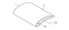
図1は、本実施形態のタービンの静翼1の概略構成を示す斜視図である。この図に示すように、静翼1は、両側の開口部を介して外部に接続される中空領域1aを備えている。なお、実際に静翼1がタービンに組み込まれた際には静翼1の両側に配置されるバンド部によって開口部が閉ざされ、中空領域1aに冷却ガスが供給されることによって静翼1の冷却が図られる。(First embodiment)
FIG. 1 is a perspective view showing a schematic configuration of a stationary blade 1 of a turbine according to the present embodiment. As shown in this figure, the stationary blade 1 includes a
また、本実施形態の静翼1は、セラミックス基複合材料によって形成されている。
セラミックス基複合材料は、セラミック(例えば炭化珪素)からなる繊維によって形成された織物に、セラミック(例えば炭化珪素)からなるマトリックスが付着形成された材料であり、金属によりも優れた耐熱性を発揮する。Further, the stationary blade 1 of the present embodiment is formed of a ceramic matrix composite material.
A ceramic matrix composite material is a material in which a matrix made of ceramic (for example, silicon carbide) is adhered to a fabric formed by fibers made of ceramic (for example, silicon carbide), and exhibits excellent heat resistance even with metal. .
そして、本実施形態の静翼1は、長さ方向における断面形状が中心軸L2を中心とする中空の同心円形状とされた織物が静翼1の形状に変形された変形織物にセラミックが含浸されて形成されている。なお、ここで言う長さ方向とは、中心軸L2が延在する方向である。
このような本実施形態の静翼1によれば、中空領域1aを介して両側の開口部に抜ける軸L周りにおける繊維の密度が均一化されて強度が均一化されるため、品質が向上されたものとなる。In the stationary blade 1 according to the present embodiment, a ceramic is impregnated into a deformed fabric obtained by transforming a fabric having a cross-sectional shape in the length direction into a hollow concentric shape centered on the central axis L2 into the shape of the stationary blade 1. Is formed. In addition, the length direction said here is a direction where the central axis L2 extends.
According to the stator blade 1 of this embodiment, the density of fibers around the axis L that passes through the openings on both sides through the
続いて、このような静翼1の製造方法について説明する。
まず最初に、図2に示すように、中心軸L2の延在方向である長さ方向における断面形状が、中心軸L2を中心とする同心円形状とされたマンドレル100を用意する。このようなマンドレル100は、長さ方向におけるいずれの領域において中心軸L2と直交する面で切断した場合には、その断面形状が真円となる。
そして、本実施形態においてマンドレル100は、長さ方向の全ての領域において、同一半径の円形状とされ、マンドレル100の長さ方向における各領域での周長が中空領域1aの長さ方向における各領域での周長と一致されている。Then, the manufacturing method of such a stationary blade 1 is demonstrated.
First, as shown in FIG. 2, a
In this embodiment, the
次に、図3に示すように、マンドレル100周りにセラミックからなる繊維を巻き付けることによって、長さ方向における断面形状が中心軸L2を中心とする中空の同心円形状とされた織物2を形成する(織物形成工程)。
なお、本実施形態においては、繊維をブレイディング法によってマンドレル100周りに巻き付ける。ブレイディング法により、マンドレル100の延在方向に延びる中央糸とマンドレル100に対して螺旋状に巻き付けられる複数の組糸とが編み込まれ、複数の繊維が同時にマンドレル100に対して巻き付けられる。Next, as shown in FIG. 3, by wrapping a fiber made of ceramic around the
In the present embodiment, the fiber is wound around the
次に、マンドレル100を織物2から抜き出す。なお、本実施形態においてマンドレル100は、長さ方向の全ての領域において同一半径の円形状とされているため、織物2を抑えて中心軸L方向に移動させることによって容易に織物2から抜き出すことができる。 Next, the
なお、セラミックス基複合材料では、周知のように繊維の表面に界面層を形成する。そして、当該界面層として炭素界面層を形成する場合には、マンドレル100を抜き出した織物2をメタンガスが供給される真空炉内において熱処理して熱分解することによって界面層を形成する。
ただし、界面層として窒化ホウ素界面層を形成する場合には、マンドレル100周りに繊維を巻き付ける前に界面層の形成を行う。具体的には、BCl3+NH3ガスが供給される炉内に繊維を通して熱分解することによって界面層の形成を行う。In the ceramic matrix composite material, an interface layer is formed on the surface of the fiber as is well known. And when forming a carbon interface layer as the said interface layer, the interface layer is formed by heat-treating the
However, when a boron nitride interface layer is formed as the interface layer, the interface layer is formed before the fibers are wound around the
次に、図4に示すように、マンドレル100を抜き出した織物2の内部に、静翼1の中空領域1aの形状に成型された内型200を挿入し、さらに織物2を内型200に押さえつけることによって織物2を静翼1の形状に変形させる。
次に、図5に示すように、織物2を上記内型200と静翼1の外形形状に成型された外型300とによって挟み込むことによって織物2を静翼1の形状に変化させた状態を保つ。なお、外型300には、後の含浸処理において原料が容易に織物2に到達可能とするために、織物2に到達する複数の貫通孔を備えている。Next, as shown in FIG. 4, the
Next, as shown in FIG. 5, the
そして、このように織物2が静翼1の形状に変化された状態で、織物2にセラミックを含浸させてマトリックスを形成する(マトリックス形成工程)。
織物2にセラミックを含浸させる方法としては、例えば気相含浸法、液相含浸法及び固相含浸法が知られている。そして、本実施形態においては、これらの方法を単独であるいは組み合わせた含浸処理を行い、さらにこれらの含浸処理を繰り返し行うことによって緻密なマトリックスの形成を行う。Then, in a state where the
As methods for impregnating the
なお、含浸工程においては織物2と内型200との隙間及び織物2と外型300との隙間にもセラミックが含浸されるため、織物2に対するセラミックの含浸が進むと、内型200及び外型300から織物2を取り外すことが困難となる。一方で、織物2は、含浸工程の初期段階(少量のセラミックが織物2に含浸された段階)でその形状が固定される。
このため、含浸工程の初期段階にて内型200及び外型300から織物2を取り外し、その後は織物2のみを対象として含浸工程を行うことが好ましい。In the impregnation process, the gap between the
For this reason, it is preferable to remove the
以上のような工程によって、図1に示す静翼1が製造される。
このような本実施形態の静翼1の製造方法によれば、長さ方向における断面形状が中心軸L2を中心とする同心円形状とされた織物2を静翼1の形状に変形し、この変形した織物2(変形織物)にセラミックが含浸されて静翼1が形成される。
長さ方向における断面形状が中心軸L2を中心とする中空の同心円形状とされた織物2は、単一断面において同一曲率となるため、マンドレル100周りに繊維を巻き付ける際に中心軸L2周りにおいて均一に繊維を配置することが可能となる。つまり、長さ方向における断面形状が中心軸L2を中心とする中空の同心円形状とされた織物2は、中心軸L2を中心とする周方向において繊維の偏りが抑制されている。そして、このような織物2を静翼1の形状に変形させた場合であっても、織物2における繊維の密度は、中心軸L2周りにおいて均一となる。
このため、本実施形態の静翼1の製造方法のように、上記織物2を静翼1の形状に変形し、この変形した織物2にセラミックが含浸されることによって、周方向に繊維が均一に配置された静翼1となる。
したがって、本実施形態の静翼1によれば、セラミックス基複合材料によって形成される静翼1の強度を均一化させて静翼1の品質を向上させることが可能となる。The stator blade 1 shown in FIG. 1 is manufactured by the process as described above.
According to the manufacturing method of the stationary blade 1 of this embodiment, the
Since the
For this reason, like the manufacturing method of the stationary blade 1 of the present embodiment, the
Therefore, according to the stationary blade 1 of the present embodiment, it is possible to improve the quality of the stationary blade 1 by making the strength of the stationary blade 1 formed of the ceramic matrix composite material uniform.
(第2実施形態)
次に、本発明の第2実施形態について説明する。なお、本第2実施形態の説明において、上記第1実施形態と同様の部分については、その説明を省略あるいは簡略化する。(Second Embodiment)
Next, a second embodiment of the present invention will be described. In the description of the second embodiment, the description of the same parts as in the first embodiment will be omitted or simplified.
図6は、本実施形態の静翼3の概略構成を示す斜視図である。この図に示すように、本実施形態の静翼3は、軸L1方向において、中央部Aの断面形状が手前側(ハブ側)の断面形状よりも大きく、奥側B(チップ側)の断面形状が手前側(ハブ側)の断面形状よりも小さい形状を有している。
本実施形成の静翼3もセラミックス基複合材料によって形成されており、内部に中空領域3aを有している。FIG. 6 is a perspective view showing a schematic configuration of the
The
そして、本実施形態の静翼3も、上記第1実施形態の静翼1と同様に、軸L周りにおける繊維の密度が均一化されて強度が均一化されており、品質が向上されたものとなっている。 And the
このような構成を有する本実施形態の静翼3を製造する場合には、図7に示すように、中心軸L2方向において中央部A1の断面形状が手前側の断面形状よりも大きい真円で、奥側B1の断面形状が手前側の断面形状よりも小さい真円とされたマンドレル600を用意する。
なお、マンドレル600の中央部A1における周長は、静翼3の中央部Aにおける中空領域3aの周長と一致されている。また、マンドレル600の奥側B1における周長は、静翼3の奥側Bにおける中空領域3aの周長と一致されている。When manufacturing the
Note that the circumferential length of the
次に、図8に示すように、マンドレル600周りにセラミックからなる繊維を巻き付けることによって、織物4を形成する。この織物4は、中心軸L2方向において断面形状が変化するものの、上記第1実施形態の織物2と同様に、中心軸L2方向の全ての領域において断面形状が中心軸L2を中心とする中空の同心円形状とされる。 Next, as shown in FIG. 8, the
次に、マンドレル600を織物4から抜き出す。なお、マンドレル600の中央部A1は、手前側及び奥側よりも大きいため、そのままマンドレル600を織物4から抜き出すことはできない。
そこで、例えば、マンドレル600を芯部とその周囲に配置される周辺部とによって構成し、芯部を抜き出すことによって分解できる構成とすることが好ましい。これによって、容易にマンドレル600を抜き出すことが可能となる。すなわち、マンドレル600は、織物4が巻き付けられた状態で分解可能に構成されていることが好ましい。
なお、この他に、マンドレル600を薬剤等によって溶解させて除去するようにすることもできる。また、マンドレル600を焼失させることによって除去するようにすることもできる。
このようにいずれかの方法を用いてマンドレル600は、織物4が巻き付けられた状態で取り外しまたは消失可能とされる。Next, the
Therefore, for example, it is preferable that the
In addition, the
As described above, the
次に、マンドレル600を抜き出した織物4の内部に、静翼3の中空領域3aの形状に成型された内型を挿入し、さらに織物4を内型に押さえつけることによって織物4を静翼3の形状に変形させる。
ここで、静翼3の中空領域3aは、静翼3の長さ方向において断面形状の大きさが変化するため、内型も同様に長さ方向において断面形状の大きさが変化する。このため、そのまま織物4の内部に内型を挿入することができない。このため、内型は、分解可能に構成されており、分解された状態で織物4の内部に入れると共に織物4の内部において組立て可能とされている。
なお、内型を焼失可能あるいは薬剤等によって溶解可能に構成し、内型を焼失あるいは溶解することによって中空領域3aから除去することもできる。
このようにいずれかの方法を用いて内型は、静翼3の中空領域3aにおいて消失可能とされる。Next, an inner mold molded in the shape of the
Here, since the size of the cross-sectional shape of the
It is also possible to remove the inner mold from the
As described above, the inner mold can be lost in the
次に、織物4を上記内型と静翼3の外形形状に成型された外型とによって挟み込むことによって織物4を静翼3の形状に変化させた状態を保ちながら、上記第1実施形態と同様に織物4にセラミックを含浸させてマトリックスを形成する。 Next, while maintaining the state in which the
以上のような本実施形態の静翼3の製造方法においても、上記第1実施形態と同様に、長さ方向における断面形状が中心軸L2を中心とする同心円形状とされた織物4を静翼3の形状に変形し、この変形した織物4(変形織物)にセラミックが含浸されて静翼3が形成される。
長さ方向における断面形状が中心軸L2を中心とする中空の同心円形状とされた織物2は、単一断面において同一曲率となるため、マンドレル600周りに繊維を巻き付ける際に中心軸L2周りにおいて均一に繊維を配置することが可能となる。つまり、長さ方向における断面形状が中心軸L2を中心とする中空の同心円形状とされた織物4は、中心軸L2を中心とする周方向において繊維の偏りが抑制されている。そして、このような織物4を静翼1の形状に変形させた場合であっても、織物4における繊維の密度は、中心軸L2周りにおいて均一となる。
このため、本実施形態の静翼3の製造方法のように、上記織物4を静翼3の形状に変形し、この変形した織物4にセラミックが含浸されることによって、周方向に繊維が均一に配置された静翼3となる。
したがって、本実施形態の静翼3によれば、セラミックス基複合材料によって形成される静翼3の強度を均一化させて静翼3の品質を向上させることが可能となる。Also in the manufacturing method of the
Since the
Therefore, as in the method of manufacturing the
Therefore, according to the
以上、図面を参照しながら本発明の好適な実施形態について説明したが、本発明は上記実施形態に限定されるものではない。上述した実施形態において示した各構成部材の諸形状や組み合わせ等は一例であって、本発明の主旨から逸脱しない範囲において設計要求等に基づき種々変更可能である。 As mentioned above, although preferred embodiment of this invention was described referring drawings, this invention is not limited to the said embodiment. Various shapes, combinations, and the like of the constituent members shown in the above-described embodiments are examples, and various modifications can be made based on design requirements and the like without departing from the gist of the present invention.
例えば、上記実施形態においては、本発明の構造物がタービンの静翼である構成について説明した。
しかしながら、本発明はこれに限定されるものではなく、本発明における構造物は、中空領域を備えると共にセラミックス基複合材料によって形成される構造物であれば良い。例えば、本発明構造物としては、タービンの静翼の他、タービンの動翼や燃焼器等を挙げることができる。For example, in the above embodiment, the configuration in which the structure of the present invention is a stationary blade of a turbine has been described.
However, this invention is not limited to this, The structure in this invention should just be a structure provided with a hollow area | region and formed with a ceramic matrix composite material. For example, examples of the structure of the present invention include a turbine blade and a combustor in addition to a turbine stationary blade.
また、上記実施形態においては、ブレイディング法によってマンドレル周りに繊維を巻き付ける構成について説明した。
しかしながら、本発明はこれに限定されるものではなく、例えばフィラメントワインディング法によってマンドレル周りに繊維を巻き付けても良い。このフィラメントワインディング法は、一本の繊維をマンドレル周りに巻き付ける方法である。このようなフィラメントワインディング法を用いてマンドレル回りに繊維を巻き付ける場合であっても、長さ方向における断面形状が中心軸を中心とする中空の同心円形状とされたマンドレル周りに繊維を巻き付けることによって、長さ方向における断面形状が中心軸を中心とする中空の同心円形状とされた織物を形成することができる。軸周りに繊維が均一な密度で配置された静翼を製造することができる。Moreover, in the said embodiment, the structure which winds a fiber around a mandrel by the braiding method was demonstrated.
However, the present invention is not limited to this, and fibers may be wound around the mandrel by, for example, a filament winding method. This filament winding method is a method of winding a single fiber around a mandrel. Even when the fiber is wound around the mandrel using such a filament winding method, by winding the fiber around the mandrel whose cross-sectional shape in the length direction is a hollow concentric circle centering on the central axis, It is possible to form a woven fabric whose cross-sectional shape in the length direction is a hollow concentric circle centered on the central axis. It is possible to manufacture a stationary blade in which fibers are arranged at a uniform density around an axis.
また、上記実施形態においては、単一の織物を変形させて静翼を製造する構成について説明した。
しかしながら、本発明はこれに限定されるものではない。
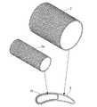
例えば、図9に示すように、上記第1実施形態において示した織物2よりも、小さな織物2a(小織物)を、織物2と同様の方法で形成し、この織物2aを織物2の内部に配置して変形することによって、中空領域1aが2つに区画された静翼を製造することもできる。
また、図10に示すように、上記第1実施形態において示した織物2よりも、小さな織物2b,2c(小織物)を、織物2と同様の方法で形成し、この織物2b,2cを織物2の内部に配置して変形することによって、中空領域1aが3つに区画された静翼を製造することもできる。
また、図11に示すように、上記第1実施形態において示した織物2よりも、小さな織物2d,2e(小織物)を、織物2と同様の方法で形成し、この織物2d,2eを織物2の内部に上下方向に配置して変形することによって、中空領域1aが上下に2つに区画された静翼を製造することもできる。Moreover, in the said embodiment, the structure which deform | transforms a single fabric and manufactures a stationary blade was demonstrated.
However, the present invention is not limited to this.
For example, as shown in FIG. 9, a
Further, as shown in FIG. 10, woven
Further, as shown in FIG. 11, woven
1,3……静翼(構造物)、1a,3a……中空領域、2,2a〜2e,4……織物、100,600……マンドレル、200……内型、300……外型 1, 3 ...... Stator blade (structure), 1 a, 3 a ...... hollow region, 2, 2 a to 2 e, 4 ...... textile, 100, 600 …… mandrel, 200 …… inner mold, 300 …… outer mold
Claims (8)
Translated fromJapanese長さ方向における断面形状が中心軸を中心とする同心円形状とされたマンドレル周りにセラミックからなる繊維を巻き付けることによって、長さ方向における断面形状が中心軸を中心とする中空の同心円形状とされた織物を形成する織物形成工程と、
該織物形成工程において形成された前記織物を前記構造物の形状に変形させた状態で、前記織物にセラミックを含浸させてマトリックスを形成するマトリックス形成工程と
を有することを特徴とする構造物の製造方法A manufacturing method of a structure including a hollow region connected to the outside through an opening and formed of a ceramic matrix composite material,
By wrapping ceramic fibers around a mandrel whose cross-sectional shape in the length direction is concentric with the central axis as the center, the cross-sectional shape in the length direction is made into a hollow concentric shape with the central axis as the center. A fabric forming process for forming a fabric;
And a matrix forming step of forming a matrix by impregnating the fabric with a ceramic in a state in which the fabric formed in the fabric forming step is deformed into the shape of the structure. Method
長さ方向における断面形状が中心軸を中心とする中空の同心円形状とされた織物が前記構造物の形状に変形された変形織物にセラミックが含浸されて形成されていることを特徴とする構造物。A structure having a hollow region connected to the outside through an opening and formed of a ceramic matrix composite material,
A structure in which a cross-sectional shape in a length direction is a hollow concentric circle centered on a central axis, and is formed by impregnating a ceramic into a deformed fabric obtained by deforming the shape of the structure. .
Priority Applications (1)
| Application Number | Priority Date | Filing Date | Title |
|---|---|---|---|
| JP2009065051AJP5093165B2 (en) | 2009-03-17 | 2009-03-17 | Structure manufacturing method and structure |
Applications Claiming Priority (1)
| Application Number | Priority Date | Filing Date | Title |
|---|---|---|---|
| JP2009065051AJP5093165B2 (en) | 2009-03-17 | 2009-03-17 | Structure manufacturing method and structure |
Publications (2)
| Publication Number | Publication Date |
|---|---|
| JP2010215459A JP2010215459A (en) | 2010-09-30 |
| JP5093165B2true JP5093165B2 (en) | 2012-12-05 |
Family
ID=42974718
Family Applications (1)
| Application Number | Title | Priority Date | Filing Date |
|---|---|---|---|
| JP2009065051AActiveJP5093165B2 (en) | 2009-03-17 | 2009-03-17 | Structure manufacturing method and structure |
Country Status (1)
| Country | Link |
|---|---|
| JP (1) | JP5093165B2 (en) |
Cited By (1)
| Publication number | Priority date | Publication date | Assignee | Title |
|---|---|---|---|---|
| EP4442856A3 (en)* | 2023-03-07 | 2024-11-20 | RTX Corporation | Chemical vapor infiltration tooling for optimizing infiltration in ceramic matrix composites |
Families Citing this family (7)
| Publication number | Priority date | Publication date | Assignee | Title |
|---|---|---|---|---|
| FR2972448B1 (en)* | 2011-03-07 | 2013-04-19 | Commissariat Energie Atomique | PROCESS FOR PRODUCING A CERAMIC MATRIX COMPOSITE |
| EP2879870A2 (en) | 2012-07-31 | 2015-06-10 | General Electric Company | Ceramic centerbody and method of making |
| WO2015021096A1 (en)* | 2013-08-07 | 2015-02-12 | Ametek, Inc. | High temperature probe |
| CN107266099B (en)* | 2017-06-16 | 2023-07-18 | 中国人民解放军第五七一九工厂 | Clamp for near-net forming of ceramic matrix composite turbine guide vane of aero-engine |
| JP6717871B2 (en)* | 2018-03-14 | 2020-07-08 | 三菱重工業株式会社 | Method for manufacturing turbine blade member |
| JP7492379B2 (en) | 2020-06-10 | 2024-05-29 | イビデン株式会社 | Heat-resistant materials |
| CN114484506B (en)* | 2022-01-27 | 2023-04-18 | 西安鑫垚陶瓷复合材料有限公司 | Shaping mold for ceramic matrix composite single-head flame tube and preparation method |
Family Cites Families (4)
| Publication number | Priority date | Publication date | Assignee | Title |
|---|---|---|---|---|
| FR2659949B1 (en)* | 1990-03-26 | 1992-12-04 | Europ Propulsion | PROCESS FOR CONFORMING A REINFORCING FIBROUS TEXTURE FOR THE MANUFACTURE OF A PART MADE OF COMPOSITE MATERIAL. |
| JPH07117026A (en)* | 1993-10-27 | 1995-05-09 | Nippon Carbon Co Ltd | Deformed ceramic fiber reinforced composite material and method for producing the same |
| JPH0925178A (en)* | 1995-05-10 | 1997-01-28 | Toshiba Corp | Ceramic-based fiber composite material and method for producing the same |
| JP4433558B2 (en)* | 1999-09-06 | 2010-03-17 | 株式会社Ihi | Manufacturing equipment for ceramic matrix composites |
- 2009
- 2009-03-17JPJP2009065051Apatent/JP5093165B2/enactiveActive
Cited By (1)
| Publication number | Priority date | Publication date | Assignee | Title |
|---|---|---|---|---|
| EP4442856A3 (en)* | 2023-03-07 | 2024-11-20 | RTX Corporation | Chemical vapor infiltration tooling for optimizing infiltration in ceramic matrix composites |
Also Published As
| Publication number | Publication date |
|---|---|
| JP2010215459A (en) | 2010-09-30 |
Similar Documents
| Publication | Publication Date | Title |
|---|---|---|
| JP5093165B2 (en) | Structure manufacturing method and structure | |
| JP5569194B2 (en) | Method for manufacturing shroud segment | |
| EP3739169A1 (en) | Cmc component with integral cooling channels and method of manufacture | |
| US12157703B2 (en) | Porous space fillers for ceramic matrix composites | |
| EP2998510B1 (en) | Composite airfoil for a gas turbine engine | |
| CN103620164B (en) | The turbine engine components forming compressor stator or turbomachine injection nozzle and the method manufacturing it | |
| JP5973589B2 (en) | Method of manufacturing a composite turbomachine vane with an integrated platform | |
| JP6563423B2 (en) | Method of manufacturing a turbine engine vane formed of a composite material, the resulting vane, and a turbine engine comprising the vane | |
| JP6018877B2 (en) | Cylindrical case and manufacturing method of cylindrical case | |
| JP2002234777A (en) | Process of making ceramic matrix composite parts with cooling channels | |
| JP2008240724A (en) | Method for producing a gas turbine casing from a composite material and the casing obtained thereby | |
| JPH05193030A (en) | Blade-form filament structure and its manufacture | |
| US20100003881A1 (en) | Methods and apparatus associated with narrow tows fabricated from large-tow preforms | |
| EP4056816B1 (en) | Vehicle muffler manufacturing method | |
| EP3693549A1 (en) | Cmc component with integral cooling channels and method of manufacture | |
| CN109751285A (en) | Fan housing with annular casing | |
| CN103402675B (en) | Method for manufacturing one-piece rotating parts | |
| JP6030124B2 (en) | Method for making single piece components for turbine engines by diffusion bonding | |
| JP2017002903A (en) | Composite disc | |
| JP4446135B2 (en) | Method and apparatus for manufacturing fiber reinforced composite member | |
| JP5359794B2 (en) | Wings and manufacturing method thereof | |
| US20200011184A1 (en) | Gas turbine blade | |
| JPH0378503A (en) | Manufacture of three dimensional fiber reinforcing structured turbine blade | |
| JP4062882B2 (en) | Method for producing three-dimensional fiber structure and method for producing carbon / carbon composite material | |
| US11608748B2 (en) | Preform crossovers for composite airfoils |
Legal Events
| Date | Code | Title | Description |
|---|---|---|---|
| A621 | Written request for application examination | Free format text:JAPANESE INTERMEDIATE CODE: A621 Effective date:20120126 | |
| A977 | Report on retrieval | Free format text:JAPANESE INTERMEDIATE CODE: A971007 Effective date:20120810 | |
| TRDD | Decision of grant or rejection written | ||
| A01 | Written decision to grant a patent or to grant a registration (utility model) | Free format text:JAPANESE INTERMEDIATE CODE: A01 Effective date:20120821 | |
| A01 | Written decision to grant a patent or to grant a registration (utility model) | Free format text:JAPANESE INTERMEDIATE CODE: A01 | |
| A61 | First payment of annual fees (during grant procedure) | Free format text:JAPANESE INTERMEDIATE CODE: A61 Effective date:20120903 | |
| R151 | Written notification of patent or utility model registration | Ref document number:5093165 Country of ref document:JP Free format text:JAPANESE INTERMEDIATE CODE: R151 | |
| FPAY | Renewal fee payment (event date is renewal date of database) | Free format text:PAYMENT UNTIL: 20150928 Year of fee payment:3 | |
| R250 | Receipt of annual fees | Free format text:JAPANESE INTERMEDIATE CODE: R250 | |
| R250 | Receipt of annual fees | Free format text:JAPANESE INTERMEDIATE CODE: R250 |