JP5090678B2 - Bone fixation device - Google Patents
Bone fixation deviceDownload PDFInfo
- Publication number
- JP5090678B2 JP5090678B2JP2006188172AJP2006188172AJP5090678B2JP 5090678 B2JP5090678 B2JP 5090678B2JP 2006188172 AJP2006188172 AJP 2006188172AJP 2006188172 AJP2006188172 AJP 2006188172AJP 5090678 B2JP5090678 B2JP 5090678B2
- Authority
- JP
- Japan
- Prior art keywords
- rod
- head
- anchoring device
- recess
- bone anchoring
- Prior art date
- Legal status (The legal status is an assumption and is not a legal conclusion. Google has not performed a legal analysis and makes no representation as to the accuracy of the status listed.)
- Active
Links
Images


Classifications
- A—HUMAN NECESSITIES
- A61—MEDICAL OR VETERINARY SCIENCE; HYGIENE
- A61B—DIAGNOSIS; SURGERY; IDENTIFICATION
- A61B17/00—Surgical instruments, devices or methods
- A61B17/56—Surgical instruments or methods for treatment of bones or joints; Devices specially adapted therefor
- A61B17/58—Surgical instruments or methods for treatment of bones or joints; Devices specially adapted therefor for osteosynthesis, e.g. bone plates, screws or setting implements
- A61B17/68—Internal fixation devices, including fasteners and spinal fixators, even if a part thereof projects from the skin
- A61B17/70—Spinal positioners or stabilisers, e.g. stabilisers comprising fluid filler in an implant
- A61B17/7001—Screws or hooks combined with longitudinal elements which do not contact vertebrae
- A61B17/7032—Screws or hooks with U-shaped head or back through which longitudinal rods pass
- A—HUMAN NECESSITIES
- A61—MEDICAL OR VETERINARY SCIENCE; HYGIENE
- A61B—DIAGNOSIS; SURGERY; IDENTIFICATION
- A61B17/00—Surgical instruments, devices or methods
- A61B17/56—Surgical instruments or methods for treatment of bones or joints; Devices specially adapted therefor
- A61B17/58—Surgical instruments or methods for treatment of bones or joints; Devices specially adapted therefor for osteosynthesis, e.g. bone plates, screws or setting implements
- A61B17/68—Internal fixation devices, including fasteners and spinal fixators, even if a part thereof projects from the skin
- A61B17/70—Spinal positioners or stabilisers, e.g. stabilisers comprising fluid filler in an implant
- A—HUMAN NECESSITIES
- A61—MEDICAL OR VETERINARY SCIENCE; HYGIENE
- A61B—DIAGNOSIS; SURGERY; IDENTIFICATION
- A61B17/00—Surgical instruments, devices or methods
- A61B17/56—Surgical instruments or methods for treatment of bones or joints; Devices specially adapted therefor
- A61B17/58—Surgical instruments or methods for treatment of bones or joints; Devices specially adapted therefor for osteosynthesis, e.g. bone plates, screws or setting implements
- A61B17/68—Internal fixation devices, including fasteners and spinal fixators, even if a part thereof projects from the skin
- A61B17/70—Spinal positioners or stabilisers, e.g. stabilisers comprising fluid filler in an implant
- A61B17/7001—Screws or hooks combined with longitudinal elements which do not contact vertebrae
- A61B17/7035—Screws or hooks, wherein a rod-clamping part and a bone-anchoring part can pivot relative to each other
- A61B17/7037—Screws or hooks, wherein a rod-clamping part and a bone-anchoring part can pivot relative to each other wherein pivoting is blocked when the rod is clamped
Landscapes
- Health & Medical Sciences (AREA)
- Orthopedic Medicine & Surgery (AREA)
- Life Sciences & Earth Sciences (AREA)
- Surgery (AREA)
- Neurology (AREA)
- Heart & Thoracic Surgery (AREA)
- Engineering & Computer Science (AREA)
- Biomedical Technology (AREA)
- Nuclear Medicine, Radiotherapy & Molecular Imaging (AREA)
- Medical Informatics (AREA)
- Molecular Biology (AREA)
- Animal Behavior & Ethology (AREA)
- General Health & Medical Sciences (AREA)
- Public Health (AREA)
- Veterinary Medicine (AREA)
- Surgical Instruments (AREA)
- Prostheses (AREA)
Description
Translated fromJapanese本発明は、骨に固定されるシャンクと頭部とを有する固定素子と、ロッドと接続するために前記頭部を受ける受け部と、前記頭部に圧力を加える圧力素子と、前記受け部と協働してロッドを受け部に締め付けるための種々の封鎖素子とを含む、骨固定装置に関する。 The present invention includes a fixing element having a shank and a head fixed to a bone, a receiving part that receives the head to connect to a rod, a pressure element that applies pressure to the head, and the receiving part. The present invention relates to a bone anchoring device comprising various sealing elements for cooperating and tightening a rod to a receiving part.
米国特許第5,443,467号は、受け部材と、ねじ山部分および頭部を有するねじ部材とを含む骨ねじを開示している。圧力ディスクは受け部材内で摺動可能であり、頭部上に作用する。ロッドが圧力ディスクの上部に置かれ、装置はロッド係止ナットを用いて係止され、係止ナットはロッド上に圧力を加え、そのときロッドは圧力ディスクに圧力を加え、従って頭部を係止する。 U.S. Pat. No. 5,443,467 discloses a bone screw including a receiving member and a screw member having a threaded portion and a head. The pressure disk is slidable within the receiving member and acts on the head. The rod is placed on top of the pressure disk and the device is locked using a rod locking nut that applies pressure on the rod, when the rod applies pressure to the pressure disk and thus engages the head. Stop.
米国特許第6,063,090号は、椎弓根ねじと、椎弓根ねじを長手方向支持と接続するためのリテイナ頭部とを備える脊椎固定システムを開示している。挿入部12が設けられ、リテイナ頭部に収納される椎弓根ねじの頭部上に圧力を加える。引っ張り手段が設けられ、その多軸位置に椎弓根ねじの頭部を係止し、長手方向支持を固定するように挿入部上を押圧する。挿入部および引っ張り手段に依存して、ロッドおよび骨ねじの頭部は別々に締め付けられ得る。 U.S. Patent No. 6,063,090 discloses a spinal fixation system comprising a pedicle screw and a retainer head for connecting the pedicle screw with a longitudinal support. An
米国特許第2003/0100896A1号は、シャンクと、ロッドに接続するためにシャンクに接続された保持素子を備えた素子であって、保持素子は、2つの開放脚部と開放脚部に内ねじ山とを備えたロッドを受けるためのU字形断面を有する凹部と、脚部の内ねじ山と協働する外ねじ山を備えた係止素子とを有する素子を開示している。1つの実施形態では、保持素子は多軸的に骨ねじの頭部と接続される。その多軸位置で頭部を係止するために、圧力ディスクが設けられ、圧力ディスクは内ねじを用いてロッド上に圧力がかけられると頭部に作用する。別の実施形態では、頭部はロッドの固定とは独立して係止可能である。2つのタイプの固定装置が手術中に同時に使用される場合は、異なるタイプの固定装置を別々に手元に有するか、または手術前または手術中に必要とされる圧力ディスクおよび/または圧力素子を備えた好適な固定装置を予め組み立てることが必要である。 US 2003/0100896 A1 is an element comprising a shank and a retaining element connected to the shank for connection to a rod, the retaining element comprising two open legs and an internal thread on the open leg. And a locking element with an external thread that cooperates with the internal thread of the leg. In one embodiment, the retaining element is polyaxially connected to the bone screw head. In order to lock the head at its multi-axial position, a pressure disk is provided, which acts on the head when pressure is applied on the rod using an internal screw. In another embodiment, the head can be locked independently of the fixation of the rod. If two types of fixation devices are used at the same time during the surgery, they have different types of fixation devices separately at hand, or have pressure disks and / or pressure elements that are required before or during the surgery It is necessary to pre-assemble a suitable fixing device.
米国特許第2004/018647381号は、受け部に多軸的に接続された骨固定素子と、その位置に頭部を係止するために頭部上に圧力を加える圧力素子とを備え、圧力素子には内ねじが設けられ、受け部にねじ込まれて、ロッド上に圧力を加えることが可能な、骨固定装置を開示している。内ねじ山はロッドが挿入された場合ロッドの上で終端し、受け部の設計がその寸法より小さくなるようにアンダーカットが設けられる。
本発明の目的は、用途が広く、コンパクトなサイズの改良された骨固定装置を提供することである。 It is an object of the present invention to provide an improved bone fixation device that is versatile and compact in size.
本目的は、請求項1または請求項12による骨固定装置によって解決される。さらなる
発展は従属項において与えられる。This object is solved by a bone anchoring device according to
本発明による骨固定装置は、2つの方法で封鎖素子を選択して使用可能であるという利点を有する。単体の封鎖素子が選択された場合、その多軸位置において頭部を同時に係止してロッドを固定することが可能である。2つの部分の封鎖素子が選択された場合は、頭部を別に係止して、ロッドを固定することが可能である。両方の適用に対して、受け部および圧力素子は1つずつ必要なだけである。従って外科医は1つの骨固定装置を使用することが可能であり、いずれの種類の封鎖機構を使用するかを手術中に選択することが可能である。 The bone anchoring device according to the invention has the advantage that the sealing element can be selected and used in two ways. When a single sealing element is selected, the rod can be fixed by simultaneously locking the head at the multi-axis position. If a two-part sealing element is selected, it is possible to lock the rod by locking the head separately. For both applications, only one receiver and one pressure element are required. Thus, the surgeon can use one bone fixation device and can choose which type of sealing mechanism to use during the operation.
脚部が斜めになるのを防止するために外ナットまたはリングを使用する必要がないので、骨固定装置のサイズはコンパクトである。また、受け部の壁厚は、構造を脆弱にするようなねじ山ランアウトまたはアンダーカットのような薄くされた内側部分をなくすようになっている。 The size of the bone anchoring device is compact because it is not necessary to use an outer nut or ring to prevent the legs from being skewed. Also, the wall thickness of the receptacle is such that there are no thinned inner portions such as thread runouts or undercuts that would weaken the structure.
本発明のさらなる特徴および利点は添付の図面と共に実施形態の説明から明らかとなるであろう。 Further features and advantages of the present invention will become apparent from the description of embodiments in conjunction with the accompanying drawings.
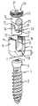
図1乃至図3に示すように、骨固定装置の第1の実施形態は、骨ねじ山を備えるシャンク2と、ねじ込みツールと係合するための凹部4を有する球欠形状頭部3とを有する骨ねじ1を含む。骨固定装置はさらに、実質的に円筒形であり、第1の端6と第1の端と対向した第2の端7とを有する受け部5を含む。2つの端は長手軸8に垂直である。長手軸8と同軸上に、第1のボア9が設けられ、第1の端6から、第2の端7からの所定距離まで延在する。第2の端7には開口10が設けられ、その直径はボア9の直径より小さい。同軸ボア9は、開口10に向かって細くなる。示される本実施形態においては、球状部11の形状で細くなる。同軸ボア9の直径は、示される実施形態においては、頭部3の最大直径よりわずかに大きいので、骨ねじ1は、シャンク2が開口10を通って延び、頭部3が球状部11に対して収まる状態で、ボア9を通って導かれることが可能である。 As shown in FIGS. 1 to 3, the first embodiment of the bone anchoring device comprises a
受け部5はさらに、U字形凹部24の底13が第2の端7から距離dを有するように第1の端6から始まり、第2の端7の方向に延在するU字形凹部12を有する。長手軸8に垂直な横方向におけるU字形凹部12の幅は、U字形凹部において受けられるロッド14の直径よりわずかに大きい。U字形凹部12により2つの自由脚部15、16が形成され、第1の端6に向かって終端する。第1の端6に隣接して、受け部は脚部15、16に内ねじ山17を含む。特に図2において理解できるように、第2の同軸ボア18が第1の端6に隣接して設けられ、ショルダ9aが第1のボア9から第2のボア18への移行において形成されるように、第2の同軸ボア18は第1の同軸ボア9の直径より大きい直径を有する。同軸ボア18の内径と内ねじ山17の対向する頂点間の内径は実質的に同じである。ねじ山17はU字形凹部12内に展開する。したがって、ねじ山のランアウト(runout)もアンダーカットもない。組み立てられた状態では、ロッド14が受け部5に挿入されると、内ねじ山17はロッド14の上面の上方にある前記脚部15、16の位置で終端する。 The
さらに、第1の端21と第1の端に対向した第2の端22を備える実質的に円筒形の構造を有する圧力素子20が設けられる。圧力素子が受け部5のボア9内に導入され、軸方向に動かされることが可能なように、外径は第1の同軸ボア9の内径よりほんのわずか小さい。組み立てられた状態で頭部3と向かい合うその第2の端に隣接して、圧力素子20はその半径が球形頭部3の半径に対応する球状凹部23を含む。その第1の端21に隣接して、圧力素子は長手軸8に対して横に延在するU字形凹部24を有する。このU字形凹
部24の横径は、受け部5で受けられるロッド14が凹部24内に挿入され、そのなかで横方向に導かれることができるように選択される。U字形凹部24により圧力素子20の開放脚部25、26が形成され、第1の端21に向かって終端する。受け部5の長手軸8の方向から見るU字形凹部24の深さは、U字形凹部24の底27にロッドが収まると、脚部25、26がロッドの上に突出するように、受けるロッド14の直径より大きい。Furthermore, a
圧力素子20はさらに、ねじ回しで骨ねじ1にアクセスできるように同軸ボア28を含む。 The
図1および図2から詳細に理解できるように、圧力素子20はその第1の端21に隣接して、円周方向突出部29を前記脚部25、26に含み、その外径は圧力素子20が第2の同軸ボア18において円周方向突出部21で摺動することができるように、受け部5の第2の同軸ボア18の内径よりわずかに小さい。 As can be understood in detail from FIGS. 1 and 2, the
骨固定装置はさらに、本実施形態においては内ねじ30の形態で単体封鎖素子である封鎖素子を含む。内ねじ30の外ねじ山は、脚部15、16に設けられた内ねじ山17と協働する。一方の端において、内ねじ30はねじ込みツールと係合する凹部31を有する。対向する端において、内ねじは第1の円筒状突出部32を有し、その直径は丁度、内ねじ30が脚部25、26の間にねじ込まれると円筒状突出部32が第2の同軸ボア18の内壁に沿って摺動する大きさである。第1の円筒状突出部32は細くなり、ロッドの直径より大きく、第2のボア18の直径より小さい直径を有し、図2の組み立て状態において、圧力素子20の第1の端21に隣接する対応円形凹部34と係合する第2の円筒状突出部33となる。第2の突出部33の自由端表面は平坦である。 The bone anchoring device further includes a sealing element which in this embodiment is a single sealing element in the form of an
骨ねじの頭部3と受け部5に対する圧力素子20の寸法は、骨ねじは受け部5に対して最終多軸位置に係止されない状態で、圧力素子20のU字形凹部24の底27が、受け部の第2の端7から距離を有し、この距離は、図3に示すように受け部5のU字形凹部12の底13の上部に突出するように、図1の示す距離dより大きくなっている。この状態において、圧力素子20は、第1の同軸ボア9において摺動可能であり、その突出部21はショルダ9aに収まらないように第2の同軸ボア18にある。軸方向における内ねじ30の寸法は、内ねじ30が締め付けられていないときは、円筒状突出部33はロッド14の表面に接触しないようになっている。 The dimensions of the
内ねじ30の寸法は、最終締め付け状態において、内ねじ30が圧力素子20上に圧力を加えない、すなわち、円筒状突出部33の長さは、内ねじの第1の円筒状突出部32の表面と圧力素子の第1の端21との間に間隙35があるようなっている。受け部の内ねじ山17および内ねじ30のねじ山は好適には平坦なねじ山であり、脚部が斜めになるのを防止する。 The dimensions of the
使用時には、まずシャフト2が開口10を通って導かれながら、頭部3が球状部11に対して、または開口10によって形成された縁部に対して収まるまで骨ねじ1が受け部5内に導入される。その後、球状凹部23が骨ねじの頭部3の上部を取り囲むように、圧力素子20が受け部5内に導入される。この状態で、圧力素子のU字形凹部の底27は、受け部5のU字形凹部の底13の上部に突出する。この状態で、骨ねじの頭部は玉継手と同様に、受け部の球状部11において旋回可能に保持される。次に、骨ねじが骨にねじ込まれる。受け部5、骨ねじ1および圧力素子20は予め組み立てられ、圧力素子20が受け部5から外れるのを防止するための手段(図示せず)を設けることができる。 In use, first the
その後、ロッド14は圧力素子20の底27に収まるように受け部内に挿入される。骨ねじと受け部との間の多軸接続ゆえに、受け部はロッドに対して正しい方向を有するよう
に配列できる。その後、円筒状突出部33の下面がロッド14の上面と接触するまで、内ねじ30が脚部15、16間にねじ込まれる。受け部5の第2の同軸ボア18の内壁は、内ねじの円筒状突出部32の案内面として作用し、これにより内ねじ30がねじ込まれる際に、内ねじの傾きを防止する。Thereafter, the
同時に、第2の同軸ボア18およびショルダ9aは受け部5に対する圧力素子20の位置合わせに役立つ。同様に、圧力素子20の環状凹部34は内ねじ30の円筒状突出部33の案内面を形成する。 At the same time, the second
図7aに示すように、内ねじ30の最終締め付け時において、内ねじ30の下面がロッドを押圧し、ロッドは圧力素子20上を押圧する。円筒状突出部33の下側と圧力素子の第1の端21との間の間隙35のために、圧力がロッドにだけ加わり、ロッドは自分で圧力素子20を介して頭部に圧力を加える。従って、頭部およびロッドは同時に固定される。 As shown in FIG. 7 a, when the
外側固定リングまたはナットは必要ないので、受け部の設計はコンパクトである。内ねじ山17はねじ山のランアウトもなく、受け部5の内側部分がアンダーカットからなることもないので、受け部5の内側に向かって厚みが増すので脚部15、16はより剛堅となる。これにより、内ねじをねじ込む際に脚部が斜めになるのが低減される。さらに、脚部がロッドの上部に突出している圧力素子は、受け部において容易に位置合わせ可能である。 Since no outer fixing ring or nut is required, the design of the receiving part is compact. Since the
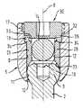
本発明の第2の実施形態が図4、図5および図7bに示される。図4および図5に示される骨固定装置は、使用される封鎖素子により図1乃至図3および図7aに示される骨固定装置とは異なる。他のすべての部分は同一であり、同じ参照符号を有する。その説明は省略する。 A second embodiment of the present invention is shown in FIGS. 4, 5 and 7b. The bone anchoring device shown in FIGS. 4 and 5 differs from the bone anchoring device shown in FIGS. 1 to 3 and 7a depending on the sealing element used. All other parts are identical and have the same reference numerals. The description is omitted.
図4および図5に示される実施形態の一部である封鎖素子は、受け部15の脚部15、16間にねじ込み可能であるナット40からなる2つの部分の封鎖素子である。ナット40は、脚部の内ねじ山17と協働する外ねじ山を有する。このねじ山は脚部が斜めになるのを防止するために平坦なねじ山が可能である。ナット40はさらに内ねじ山42が備えられる。一方の端には、ねじ回しと係合させるためにスリット43が設けられる。受け部5と向かい合う側に、ナット40は外径が第2の同軸ボア18の内径よりわずかに小さい環状突出部44を有する。 The sealing element that is part of the embodiment shown in FIGS. 4 and 5 is a two-part sealing element consisting of a
封鎖素子はさらに、ナット40の内ねじ山42と協働する外ねじ山を備えた内ねじまたは位置決めねじ45を含む。ねじ山はメートルねじが可能である。内ねじ45はねじ込みツールと係合させるための凹部46を有する。ナット40の寸法は、図4に示すような完全に締め付けられた状態では、環状突出部44が圧力素子20の第1の端21上を押圧するようになっている。内ねじ46の寸法は、完全に締め付けられた状態でロッドを押圧するようになっている。 The sealing element further includes an internal screw or set
使用時には、第1の実施形態と同様に、まずねじ素子が受け部に導入される。その後、圧力素子20が受け部に挿入され、そこで緩く保持される。同軸第1のボア9と同軸第2のボア18のために圧力素子の位置合わせは容易である。これに続いて、骨ねじが骨にねじ込まれて、圧力素子のU字形凹部24に位置合わせされた受け部のU字形凹部12にロッド14が挿入される。ロッドを入れる際に、そのU字形凹部の底27が受け部5のU字形凹部の底13上に突出するように圧力素子が位置付けられる。また、ねじ素子、受け部および圧力素子は予め組み立て可能である。 In use, as in the first embodiment, the screw element is first introduced into the receiving portion. Thereafter, the
その後、内ねじ45が緩くナット40にねじ込まれた状態で、ナット40が圧力素子の脚部25、26の上端に当接し、圧力素子20に下向きの力を加え、これがねじ頭部3を押圧して受け部5におけるその最終多軸位置にねじを係止するまで、ナット40がねじ込まれる。圧力素子20の脚部25、26はロッド上部に突出しているので、この状態でロッド14は圧力素子20のU字形凹部において尚、摺動可能である。加えて、ナット40によりロッド14が外れたり、傾いたりするのが防止される。最後に、内ねじ45がロッド14上を押圧してこれを固定するまで締め付けられる。図7bに示されるように、ロッドの固定は頭部の固定と独立して行われる。 Thereafter, with the
第1の実施形態と同様に、外側締め付け素子は必要ないので骨固定装置はコンパクトである。さらに、圧力素子の位置合わせが容易にされる。 Similar to the first embodiment, the bone fixation device is compact because no external clamping elements are required. Furthermore, alignment of the pressure element is facilitated.
図6に示すように、外科医は、手術中に同じ骨固定装置で単体の封鎖素子30または2つの部分の封鎖素子40、45を使用するかを選択可能である。一定の用途では、特に固定を速やかに行わなければならない場合には、同時に頭部の係止およびロッドの固定を備えた単体の封鎖素子が有利である。一定の他の用途では、頭部とロッドの別々の固定を有するのが有利である。外科医は同一の骨固定装置を使用することができ、自由に所望の封鎖素子を選択できるので、異なる圧力素子または異なる骨固定装置を利用可能とする、異なる受け部を有する必要がない。 As shown in FIG. 6, the surgeon can choose to use a
実施形態の変形が可能である。平坦なねじ山の代わりに他のねじ山形状が使用可能である。これは、脚部の外ねじ山と協働するリングまたはナットなどのさらなる外側締め付け素子を必要とし得る。内ねじ山を省略し、ロッド上を押圧する締め付けピンを備えたキャップを使用することも考えられる。この場合、ピンは、ロッドと接触したときに圧力素子の第1の端21上を押圧しないような形状にすべきである。 Variations of the embodiment are possible. Other thread shapes can be used instead of flat threads. This may require additional outer clamping elements such as rings or nuts that cooperate with the outer threads of the legs. It is also conceivable to use a cap with a clamping pin that presses on the rod, omitting the inner thread. In this case, the pin should be shaped so that it does not press on the
頭部3が収まる受け部の部分11は球状である必要はなく、頭部3が玉継手のように開口10の縁部により保持される限り、他の任意の形状を有することができる。 The
さらなる変形が可能である。第2の実施形態では、ナット40は、円筒状突出部44から離れたその対向端においてさらなるキャップ部分を有し、脚部が斜めになる危険性を除去し得る。加えて、第1の実施形態と同様の変形が考えられる。さらなる変形では、受け部は、受け部の底から、すなわち第2の端からの頭部の導入を可能とするように設計される。 Further variations are possible. In the second embodiment, the
Claims (11)
Translated fromJapanese骨または椎骨に固定されるシャンク(2)と頭部(3)とを含む固定素子(1)と、
受け部(5)であって、第1の端(6)と、第1の端に対向する第2の端(7)と、2つの端を通る長手軸(8)と、長手軸と同軸のボア(9,18)と、前記頭部を受けるための第2の端(7)に隣接した第1の領域(11)と、第1の端(6)に向かって開口し、ロッド(14)を受けるための2つの自由脚部(15、16)を形成する第1の凹部(12)とを含む受け部(5)と、
前記頭部(3)に圧力を加えて、前記受け部(5)に前記頭部を係止する圧力素子(20)と、
前記脚部(15、16)と協働して前記第1の凹部(12)においてロッド(14)を締め付けるとともに、ロッド(14)に作用して、頭部(3)およびロッド(14)を同時に固定する、第1の封鎖素子(30)と、
前記脚部(15、16)と協働して前記第1の凹部(12)においてロッド(14)を締め付けるとともに、前記圧力素子(20)とロッド(14)に作用して、頭部(3)とロッド(14)とを互いに独立して固定する、第2の封鎖素子(40、45)とを含み、
前記第1の封鎖素子と前記第2の封鎖素子は交換可能に使用でき、
前記圧力素子(20)は、第1の端(21)および第1の端(21)に対向する第2の端(22)、ならびに第1の端(21)に向かって開口しロッド(14)を受ける第2の凹部(24)を有し、
内ねじ山(17)が前記脚部(15、16)に設けられ、前記第1の封鎖素子は前記脚部(15、16)間にねじ込まれて、前記ロッド(14)にのみ圧力が加わる内ねじ(30)である、骨固定装置。A bone anchoring device,
A fixation element (1) comprising a shank (2) fixed to a bone or vertebra and a head (3);
A receiving part (5), a first end (6), a second end (7) opposite the first end, a longitudinal axis (8) passing through the two ends, and coaxial with the longitudinal axis A bore (9,18 ), a first region (11) adjacent to a second end (7) for receiving the head, an opening towards the first end (6) and a rod ( 14) a receiving part (5) comprising afirst recess (12) forming two free legs (15, 16) for receiving;
Applying pressure to said head (3),wherein the receiving portion (5) a pressure element for locking the head (20),
The rod (14) is tightened inthe first recess (12) in cooperation with the legs (15, 16), and acts on the rod (14) to attach the head (3) and the rod (14). A first sealing element (30), which is fixed simultaneously;
With tightening the rod(14) in the cooperating with said legs (15, 16)the first recess (12), actsthe pressure element (20) to the rod (14), the head (3 ) And the rod (14) independently of each other, a second sealing element (40, 45),
Wherein the first blockade element second blockade elementcan interchangeablyused,
The pressure element (20) opens toward the first end (21), the second end (22) opposite to the first end (21), and the first end (21), and the rod (14). ) Having a second recess (24) for receiving
An inner thread (17) is provided on the legs (15, 16), and the first sealing element is screwed between the legs (15, 16) to apply pressure only to the rod (14). A bone anchoring devicewhich is aninternal screw (30) .
Applications Claiming Priority (4)
| Application Number | Priority Date | Filing Date | Title |
|---|---|---|---|
| US69888505P | 2005-07-12 | 2005-07-12 | |
| EP05015138.0 | 2005-07-12 | ||
| EP05015138AEP1743584B1 (en) | 2005-07-12 | 2005-07-12 | Bone anchoring device |
| US60/698,885 | 2005-07-12 |
Publications (2)
| Publication Number | Publication Date |
|---|---|
| JP2007021206A JP2007021206A (en) | 2007-02-01 |
| JP5090678B2true JP5090678B2 (en) | 2012-12-05 |
Family
ID=35355878
Family Applications (1)
| Application Number | Title | Priority Date | Filing Date |
|---|---|---|---|
| JP2006188172AActiveJP5090678B2 (en) | 2005-07-12 | 2006-07-07 | Bone fixation device |
Country Status (8)
| Country | Link |
|---|---|
| US (3) | US7955359B2 (en) |
| EP (2) | EP1769761B1 (en) |
| JP (1) | JP5090678B2 (en) |
| KR (3) | KR101406237B1 (en) |
| CN (2) | CN101966096B (en) |
| DE (2) | DE602005002477T2 (en) |
| ES (2) | ES2294601T3 (en) |
| TW (1) | TWI391121B (en) |
Families Citing this family (166)
| Publication number | Priority date | Publication date | Assignee | Title |
|---|---|---|---|---|
| US7833250B2 (en) | 2004-11-10 | 2010-11-16 | Jackson Roger P | Polyaxial bone screw with helically wound capture connection |
| US20160242816A9 (en)* | 2001-05-09 | 2016-08-25 | Roger P. Jackson | Dynamic spinal stabilization assembly with elastic bumpers and locking limited travel closure mechanisms |
| US10729469B2 (en)* | 2006-01-09 | 2020-08-04 | Roger P. Jackson | Flexible spinal stabilization assembly with spacer having off-axis core member |
| US7862587B2 (en) | 2004-02-27 | 2011-01-04 | Jackson Roger P | Dynamic stabilization assemblies, tool set and method |
| US10258382B2 (en) | 2007-01-18 | 2019-04-16 | Roger P. Jackson | Rod-cord dynamic connection assemblies with slidable bone anchor attachment members along the cord |
| US8353932B2 (en)* | 2005-09-30 | 2013-01-15 | Jackson Roger P | Polyaxial bone anchor assembly with one-piece closure, pressure insert and plastic elongate member |
| US8292926B2 (en) | 2005-09-30 | 2012-10-23 | Jackson Roger P | Dynamic stabilization connecting member with elastic core and outer sleeve |
| WO2006052796A2 (en) | 2004-11-10 | 2006-05-18 | Jackson Roger P | Helical guide and advancement flange with break-off extensions |
| US8876868B2 (en) | 2002-09-06 | 2014-11-04 | Roger P. Jackson | Helical guide and advancement flange with radially loaded lip |
| US6716214B1 (en) | 2003-06-18 | 2004-04-06 | Roger P. Jackson | Polyaxial bone screw with spline capture connection |
| US7621918B2 (en) | 2004-11-23 | 2009-11-24 | Jackson Roger P | Spinal fixation tool set and method |
| US7377923B2 (en) | 2003-05-22 | 2008-05-27 | Alphatec Spine, Inc. | Variable angle spinal screw assembly |
| US8377102B2 (en) | 2003-06-18 | 2013-02-19 | Roger P. Jackson | Polyaxial bone anchor with spline capture connection and lower pressure insert |
| US8926670B2 (en) | 2003-06-18 | 2015-01-06 | Roger P. Jackson | Polyaxial bone screw assembly |
| US8137386B2 (en) | 2003-08-28 | 2012-03-20 | Jackson Roger P | Polyaxial bone screw apparatus |
| US7776067B2 (en) | 2005-05-27 | 2010-08-17 | Jackson Roger P | Polyaxial bone screw with shank articulation pressure insert and method |
| US7766915B2 (en)* | 2004-02-27 | 2010-08-03 | Jackson Roger P | Dynamic fixation assemblies with inner core and outer coil-like member |
| US8257398B2 (en) | 2003-06-18 | 2012-09-04 | Jackson Roger P | Polyaxial bone screw with cam capture |
| US8398682B2 (en) | 2003-06-18 | 2013-03-19 | Roger P. Jackson | Polyaxial bone screw assembly |
| US7967850B2 (en) | 2003-06-18 | 2011-06-28 | Jackson Roger P | Polyaxial bone anchor with helical capture connection, insert and dual locking assembly |
| US7179261B2 (en) | 2003-12-16 | 2007-02-20 | Depuy Spine, Inc. | Percutaneous access devices and bone anchor assemblies |
| US11419642B2 (en) | 2003-12-16 | 2022-08-23 | Medos International Sarl | Percutaneous access devices and bone anchor assemblies |
| US7527638B2 (en) | 2003-12-16 | 2009-05-05 | Depuy Spine, Inc. | Methods and devices for minimally invasive spinal fixation element placement |
| US7160300B2 (en) | 2004-02-27 | 2007-01-09 | Jackson Roger P | Orthopedic implant rod reduction tool set and method |
| JP2007525274A (en) | 2004-02-27 | 2007-09-06 | ロジャー・ピー・ジャクソン | Orthopedic implant rod reduction instrument set and method |
| US11241261B2 (en) | 2005-09-30 | 2022-02-08 | Roger P Jackson | Apparatus and method for soft spinal stabilization using a tensionable cord and releasable end structure |
| US8152810B2 (en) | 2004-11-23 | 2012-04-10 | Jackson Roger P | Spinal fixation tool set and method |
| US7503924B2 (en) | 2004-04-08 | 2009-03-17 | Globus Medical, Inc. | Polyaxial screw |
| US8475495B2 (en) | 2004-04-08 | 2013-07-02 | Globus Medical | Polyaxial screw |
| US7901435B2 (en)* | 2004-05-28 | 2011-03-08 | Depuy Spine, Inc. | Anchoring systems and methods for correcting spinal deformities |
| US20060058788A1 (en)* | 2004-08-27 | 2006-03-16 | Hammer Michael A | Multi-axial connection system |
| US8951290B2 (en) | 2004-08-27 | 2015-02-10 | Blackstone Medical, Inc. | Multi-axial connection system |
| US7651502B2 (en) | 2004-09-24 | 2010-01-26 | Jackson Roger P | Spinal fixation tool set and method for rod reduction and fastener insertion |
| US8926672B2 (en) | 2004-11-10 | 2015-01-06 | Roger P. Jackson | Splay control closure for open bone anchor |
| US9168069B2 (en) | 2009-06-15 | 2015-10-27 | Roger P. Jackson | Polyaxial bone anchor with pop-on shank and winged insert with lower skirt for engaging a friction fit retainer |
| US9216041B2 (en) | 2009-06-15 | 2015-12-22 | Roger P. Jackson | Spinal connecting members with tensioned cords and rigid sleeves for engaging compression inserts |
| WO2006057837A1 (en) | 2004-11-23 | 2006-06-01 | Jackson Roger P | Spinal fixation tool attachment structure |
| US8308782B2 (en) | 2004-11-23 | 2012-11-13 | Jackson Roger P | Bone anchors with longitudinal connecting member engaging inserts and closures for fixation and optional angulation |
| US8444681B2 (en) | 2009-06-15 | 2013-05-21 | Roger P. Jackson | Polyaxial bone anchor with pop-on shank, friction fit retainer and winged insert |
| US7875065B2 (en)* | 2004-11-23 | 2011-01-25 | Jackson Roger P | Polyaxial bone screw with multi-part shank retainer and pressure insert |
| US9980753B2 (en) | 2009-06-15 | 2018-05-29 | Roger P Jackson | pivotal anchor with snap-in-place insert having rotation blocking extensions |
| US10076361B2 (en) | 2005-02-22 | 2018-09-18 | Roger P. Jackson | Polyaxial bone screw with spherical capture, compression and alignment and retention structures |
| US7901437B2 (en) | 2007-01-26 | 2011-03-08 | Jackson Roger P | Dynamic stabilization member with molded connection |
| US8105368B2 (en) | 2005-09-30 | 2012-01-31 | Jackson Roger P | Dynamic stabilization connecting member with slitted core and outer sleeve |
| US12357348B2 (en) | 2005-09-30 | 2025-07-15 | Roger P. Jackson | Method of assembling a pivotal bone anchor assembly with press-in-place insert |
| US7833252B2 (en) | 2006-01-27 | 2010-11-16 | Warsaw Orthopedic, Inc. | Pivoting joints for spinal implants including designed resistance to motion and methods of use |
| US7722652B2 (en) | 2006-01-27 | 2010-05-25 | Warsaw Orthopedic, Inc. | Pivoting joints for spinal implants including designed resistance to motion and methods of use |
| US8057519B2 (en)* | 2006-01-27 | 2011-11-15 | Warsaw Orthopedic, Inc. | Multi-axial screw assembly |
| CA2647026A1 (en) | 2006-03-22 | 2008-08-28 | Pioneer Surgical Technology, Inc. | Low top bone fixation system and method for using the same |
| US8361129B2 (en)* | 2006-04-28 | 2013-01-29 | Depuy Spine, Inc. | Large diameter bone anchor assembly |
| US8062340B2 (en) | 2006-08-16 | 2011-11-22 | Pioneer Surgical Technology, Inc. | Spinal rod anchor device and method |
| CA2670988C (en) | 2006-12-08 | 2014-03-25 | Roger P. Jackson | Tool system for dynamic spinal implants |
| US8366745B2 (en)* | 2007-05-01 | 2013-02-05 | Jackson Roger P | Dynamic stabilization assembly having pre-compressed spacers with differential displacements |
| US8475498B2 (en) | 2007-01-18 | 2013-07-02 | Roger P. Jackson | Dynamic stabilization connecting member with cord connection |
| US10792074B2 (en) | 2007-01-22 | 2020-10-06 | Roger P. Jackson | Pivotal bone anchor assemly with twist-in-place friction fit insert |
| US10383660B2 (en) | 2007-05-01 | 2019-08-20 | Roger P. Jackson | Soft stabilization assemblies with pretensioned cords |
| US8979904B2 (en) | 2007-05-01 | 2015-03-17 | Roger P Jackson | Connecting member with tensioned cord, low profile rigid sleeve and spacer with torsion control |
| US8197518B2 (en) | 2007-05-16 | 2012-06-12 | Ortho Innovations, Llc | Thread-thru polyaxial pedicle screw system |
| US7942910B2 (en) | 2007-05-16 | 2011-05-17 | Ortho Innovations, Llc | Polyaxial bone screw |
| US7947065B2 (en) | 2008-11-14 | 2011-05-24 | Ortho Innovations, Llc | Locking polyaxial ball and socket fastener |
| US7942909B2 (en) | 2009-08-13 | 2011-05-17 | Ortho Innovations, Llc | Thread-thru polyaxial pedicle screw system |
| US7951173B2 (en) | 2007-05-16 | 2011-05-31 | Ortho Innovations, Llc | Pedicle screw implant system |
| US7942911B2 (en) | 2007-05-16 | 2011-05-17 | Ortho Innovations, Llc | Polyaxial bone screw |
| PL2170192T3 (en)* | 2007-07-20 | 2011-07-29 | Synthes Gmbh | Polyaxial bone fixation element |
| US8801758B2 (en)* | 2007-08-13 | 2014-08-12 | Stryker Spine | Insertion instrument for intervertebral implants |
| US8398683B2 (en) | 2007-10-23 | 2013-03-19 | Pioneer Surgical Technology, Inc. | Rod coupling assembly and methods for bone fixation |
| US9232968B2 (en)* | 2007-12-19 | 2016-01-12 | DePuy Synthes Products, Inc. | Polymeric pedicle rods and methods of manufacturing |
| US8007522B2 (en)* | 2008-02-04 | 2011-08-30 | Depuy Spine, Inc. | Methods for correction of spinal deformities |
| US9060813B1 (en) | 2008-02-29 | 2015-06-23 | Nuvasive, Inc. | Surgical fixation system and related methods |
| US20090326583A1 (en)* | 2008-06-25 | 2009-12-31 | Missoum Moumene | Posterior Dynamic Stabilization System With Flexible Ligament |
| US20090326584A1 (en)* | 2008-06-27 | 2009-12-31 | Michael Andrew Slivka | Spinal Dynamic Stabilization Rods Having Interior Bumpers |
| AU2010260521C1 (en) | 2008-08-01 | 2013-08-01 | Roger P. Jackson | Longitudinal connecting member with sleeved tensioned cords |
| US8506601B2 (en) | 2008-10-14 | 2013-08-13 | Pioneer Surgical Technology, Inc. | Low profile dual locking fixation system and offset anchor member |
| US8075603B2 (en) | 2008-11-14 | 2011-12-13 | Ortho Innovations, Llc | Locking polyaxial ball and socket fastener |
| ES2378588T3 (en) | 2008-12-30 | 2012-04-16 | Biedermann Motech Gmbh | Receiving part for receiving a rod for coupling the rod in a bone anchoring element and bone anchoring device with such receiving part |
| US8636778B2 (en) | 2009-02-11 | 2014-01-28 | Pioneer Surgical Technology, Inc. | Wide angulation coupling members for bone fixation system |
| US8641734B2 (en)* | 2009-02-13 | 2014-02-04 | DePuy Synthes Products, LLC | Dual spring posterior dynamic stabilization device with elongation limiting elastomers |
| KR101041373B1 (en)* | 2009-04-30 | 2011-06-15 | 김민석 | Spinal fixation device including set screw with double spiral |
| US9668771B2 (en) | 2009-06-15 | 2017-06-06 | Roger P Jackson | Soft stabilization assemblies with off-set connector |
| US8998959B2 (en) | 2009-06-15 | 2015-04-07 | Roger P Jackson | Polyaxial bone anchors with pop-on shank, fully constrained friction fit retainer and lock and release insert |
| US11229457B2 (en) | 2009-06-15 | 2022-01-25 | Roger P. Jackson | Pivotal bone anchor assembly with insert tool deployment |
| CN103826560A (en) | 2009-06-15 | 2014-05-28 | 罗杰.P.杰克逊 | Polyaxial Bone Anchor with Socket Stem and Winged Inserts with Friction Fit Compression Collars |
| US8876869B1 (en) | 2009-06-19 | 2014-11-04 | Nuvasive, Inc. | Polyaxial bone screw assembly |
| USD746461S1 (en)* | 2009-06-19 | 2015-12-29 | Life Spine, Inc. | Spinal rod connector |
| US9320543B2 (en) | 2009-06-25 | 2016-04-26 | DePuy Synthes Products, Inc. | Posterior dynamic stabilization device having a mobile anchor |
| KR101047938B1 (en)* | 2009-07-03 | 2011-07-11 | 주식회사 솔고 바이오메디칼 | Pedicle screw |
| KR101047936B1 (en)* | 2009-07-03 | 2011-07-11 | 주식회사 솔고 바이오메디칼 | Pedicle screw |
| EP2286748B1 (en)* | 2009-08-20 | 2014-05-28 | Biedermann Technologies GmbH & Co. KG | Bone anchoring device |
| EP2485654B1 (en) | 2009-10-05 | 2021-05-05 | Jackson P. Roger | Polyaxial bone anchor with non-pivotable retainer and pop-on shank, some with friction fit |
| US8361123B2 (en) | 2009-10-16 | 2013-01-29 | Depuy Spine, Inc. | Bone anchor assemblies and methods of manufacturing and use thereof |
| US8663289B2 (en)* | 2009-10-29 | 2014-03-04 | Warsaw Orthopedic, Inc. | Pedicle screw head extender |
| DE112010004338B4 (en) | 2009-11-10 | 2019-06-27 | Nuvasive, Inc. | DEVICE FOR IMPLEMENTING SPINE SURGERY |
| ES2525046T3 (en)* | 2009-12-21 | 2014-12-16 | Biedermann Technologies Gmbh & Co. Kg | Bone anchoring device |
| TWI383770B (en)* | 2010-01-08 | 2013-02-01 | Orthopedic with a universal pad | |
| US8636655B1 (en) | 2010-01-19 | 2014-01-28 | Ronald Childs | Tissue retraction system and related methods |
| US9445844B2 (en)* | 2010-03-24 | 2016-09-20 | DePuy Synthes Products, Inc. | Composite material posterior dynamic stabilization spring rod |
| US12383311B2 (en) | 2010-05-14 | 2025-08-12 | Roger P. Jackson | Pivotal bone anchor assembly and method for use thereof |
| KR101120413B1 (en)* | 2010-08-13 | 2012-03-16 | (주)투앤알바이오메드 | Pedicle fixing screw capable of rugulating mounting position of a spine rod |
| WO2012030712A1 (en) | 2010-08-30 | 2012-03-08 | Zimmer Spine, Inc. | Polyaxial pedicle screw |
| AU2011299558A1 (en) | 2010-09-08 | 2013-05-02 | Roger P. Jackson | Dynamic stabilization members with elastic and inelastic sections |
| AU2011324058A1 (en) | 2010-11-02 | 2013-06-20 | Roger P. Jackson | Polyaxial bone anchor with pop-on shank and pivotable retainer |
| US9198692B1 (en) | 2011-02-10 | 2015-12-01 | Nuvasive, Inc. | Spinal fixation anchor |
| US9387013B1 (en) | 2011-03-01 | 2016-07-12 | Nuvasive, Inc. | Posterior cervical fixation system |
| JP5865479B2 (en) | 2011-03-24 | 2016-02-17 | ロジャー・ピー・ジャクソン | Multiaxial bone anchor with compound joint and pop-mounted shank |
| US9307972B2 (en) | 2011-05-10 | 2016-04-12 | Nuvasive, Inc. | Method and apparatus for performing spinal fusion surgery |
| US8888827B2 (en) | 2011-07-15 | 2014-11-18 | Globus Medical, Inc. | Orthopedic fixation devices and methods of installation thereof |
| US9993269B2 (en) | 2011-07-15 | 2018-06-12 | Globus Medical, Inc. | Orthopedic fixation devices and methods of installation thereof |
| US9358047B2 (en) | 2011-07-15 | 2016-06-07 | Globus Medical, Inc. | Orthopedic fixation devices and methods of installation thereof |
| US9186187B2 (en) | 2011-07-15 | 2015-11-17 | Globus Medical, Inc. | Orthopedic fixation devices and methods of installation thereof |
| US9198694B2 (en) | 2011-07-15 | 2015-12-01 | Globus Medical, Inc. | Orthopedic fixation devices and methods of installation thereof |
| CN102949229B (en)* | 2011-08-23 | 2015-01-28 | 常州市康辉医疗器械有限公司 | One-way automatic stretching pedicle screw and application thereof |
| EP2574297B1 (en) | 2011-09-30 | 2015-11-11 | Biedermann Technologies GmbH & Co. KG | Bone anchoring device and tool cooperating with such a bone anchoring device |
| US20130096618A1 (en)* | 2011-10-14 | 2013-04-18 | Thibault Chandanson | Bone anchor assemblies |
| KR101296678B1 (en)* | 2011-10-26 | 2013-08-16 | 서승우 | anti bleeding element and bone screw for anti bleeding having thereof |
| EP2591738A1 (en)* | 2011-11-14 | 2013-05-15 | Biedermann Technologies GmbH & Co. KG | Polyaxial bone anchoring device |
| US8911479B2 (en) | 2012-01-10 | 2014-12-16 | Roger P. Jackson | Multi-start closures for open implants |
| US9271759B2 (en) | 2012-03-09 | 2016-03-01 | Institute Of Musculoskeletal Science And Education, Ltd. | Pedicle screw assembly with locking cap |
| EP2674123B1 (en) | 2012-06-11 | 2018-03-21 | Biedermann Technologies GmbH & Co. KG | Polyaxial bone anchoring device |
| EP2687171B1 (en) | 2012-07-18 | 2015-04-22 | Biedermann Technologies GmbH & Co. KG | Polyaxial bone anchoring device |
| US9011450B2 (en) | 2012-08-08 | 2015-04-21 | DePuy Synthes Products, LLC | Surgical instrument |
| US8911478B2 (en) | 2012-11-21 | 2014-12-16 | Roger P. Jackson | Splay control closure for open bone anchor |
| CN103006308A (en)* | 2012-12-27 | 2013-04-03 | 苏州欣荣博尔特医疗器械有限公司 | Spine bolt |
| US10058354B2 (en) | 2013-01-28 | 2018-08-28 | Roger P. Jackson | Pivotal bone anchor assembly with frictional shank head seating surfaces |
| US8852239B2 (en) | 2013-02-15 | 2014-10-07 | Roger P Jackson | Sagittal angle screw with integral shank and receiver |
| US20140336709A1 (en)* | 2013-03-13 | 2014-11-13 | Baxano Surgical, Inc. | Multi-threaded pedicle screw system |
| US9259247B2 (en) | 2013-03-14 | 2016-02-16 | Medos International Sarl | Locking compression members for use with bone anchor assemblies and methods |
| US10342582B2 (en) | 2013-03-14 | 2019-07-09 | DePuy Synthes Products, Inc. | Bone anchor assemblies and methods with improved locking |
| DE102013204726B4 (en)* | 2013-03-18 | 2017-08-10 | Silony Medical International AG | osteosynthesis |
| US9453526B2 (en) | 2013-04-30 | 2016-09-27 | Degen Medical, Inc. | Bottom-loading anchor assembly |
| EP2851021B1 (en)* | 2013-09-19 | 2016-12-14 | Biedermann Technologies GmbH & Co. KG | Coupling assembly for coupling a rod to a bone anchoring element, polyaxial bone anchoring device and modular stabilization device |
| US9566092B2 (en) | 2013-10-29 | 2017-02-14 | Roger P. Jackson | Cervical bone anchor with collet retainer and outer locking sleeve |
| US9717533B2 (en) | 2013-12-12 | 2017-08-01 | Roger P. Jackson | Bone anchor closure pivot-splay control flange form guide and advancement structure |
| US9451993B2 (en) | 2014-01-09 | 2016-09-27 | Roger P. Jackson | Bi-radial pop-on cervical bone anchor |
| US9597119B2 (en) | 2014-06-04 | 2017-03-21 | Roger P. Jackson | Polyaxial bone anchor with polymer sleeve |
| US10064658B2 (en) | 2014-06-04 | 2018-09-04 | Roger P. Jackson | Polyaxial bone anchor with insert guides |
| DE102014215529A1 (en) | 2014-08-06 | 2016-02-11 | Silony Medical International AG | osteosynthesis |
| US9795370B2 (en) | 2014-08-13 | 2017-10-24 | Nuvasive, Inc. | Minimally disruptive retractor and associated methods for spinal surgery |
| US10543021B2 (en) | 2014-10-21 | 2020-01-28 | Roger P. Jackson | Pivotal bone anchor assembly having an open ring positioner for a retainer |
| DE102015109481A1 (en)* | 2015-06-15 | 2016-12-15 | Aesculap Ag | Pedicle screw with radially offset guide |
| JP6643364B2 (en) | 2015-06-25 | 2020-02-12 | インスティテュート フォー マスキュロスケレタル サイエンス アンド エジュケイション,リミテッド | Interbody fusion device and system for implantation |
| EP3158957B1 (en)* | 2015-10-21 | 2020-02-12 | Biedermann Technologies GmbH & Co. KG | Coupling device for coupling a bone anchor to a rod and bone anchoring device with such a coupling device |
| CN105213009A (en)* | 2015-10-30 | 2016-01-06 | 北京市富乐科技开发有限公司 | The two plug screw screw of Wicresoft |
| DE102016113495A1 (en)* | 2016-07-21 | 2018-01-25 | Aesculap Ag | Pedicle screw system with a locking screw with threaded section |
| EP3278750B1 (en) | 2016-08-04 | 2018-12-12 | Biedermann Technologies GmbH & Co. KG | Polyaxial bone anchoring device and system of an instrument and a polyaxial bone anchoring device |
| DE102016215694B4 (en) | 2016-08-22 | 2018-06-21 | Premiere Medical Gmbh | Polyaxial pedicle screw with locking device |
| EP3287089B1 (en) | 2016-08-24 | 2019-07-24 | Biedermann Technologies GmbH & Co. KG | Polyaxial bone anchoring device and system of an instrument and a polyaxial bone anchoring device |
| US10307265B2 (en) | 2016-10-18 | 2019-06-04 | Institute for Musculoskeletal Science and Education, Ltd. | Implant with deployable blades |
| US10405992B2 (en) | 2016-10-25 | 2019-09-10 | Institute for Musculoskeletal Science and Education, Ltd. | Spinal fusion implant |
| US10610265B1 (en) | 2017-07-31 | 2020-04-07 | K2M, Inc. | Polyaxial bone screw with increased angulation |
| EP3476340B1 (en) | 2017-10-25 | 2021-06-02 | Biedermann Technologies GmbH & Co. KG | Polyaxial bone anchoring device |
| EP3536271B1 (en) | 2018-03-06 | 2022-05-04 | Biedermann Technologies GmbH & Co. KG | Polyaxial bone anchoring device and system of an instrument and a polyaxial bone anchoring device |
| EP3695796B1 (en)* | 2019-02-13 | 2022-08-03 | Biedermann Technologies GmbH & Co. KG | Anchoring assembly for anchoring a rod to a bone or a vertebra |
| EP3730078B1 (en)* | 2019-04-26 | 2021-06-09 | Biedermann Technologies GmbH & Co. KG | Closure assembly for securing a stabilization element in a receiving part of a bone anchoring device |
| US11571244B2 (en) | 2019-05-22 | 2023-02-07 | Nuvasive, Inc. | Posterior spinal fixation screws |
| US20210169531A1 (en)* | 2019-12-09 | 2021-06-10 | Globus Medical, Inc. | Dual locking polyaxial screw head |
| USD956233S1 (en)* | 2020-04-24 | 2022-06-28 | Solco Biomedical Co., Ltd. | Cervical screw |
| WO2021263088A1 (en) | 2020-06-26 | 2021-12-30 | K2M, Inc. | Modular head assembly |
| WO2022108875A1 (en) | 2020-11-19 | 2022-05-27 | K2M, Inc. | Modular head assembly for spinal fixation |
| US11627995B2 (en) | 2020-12-21 | 2023-04-18 | Warsaw Orthopedic, Inc. | Locking-cap module and connector |
| US11627992B2 (en) | 2020-12-21 | 2023-04-18 | Warsaw Orthopedic, Inc. | Locking-cap module and connector |
| WO2022184797A1 (en) | 2021-03-05 | 2022-09-09 | Medos International Sarl | Selectively locking polyaxial screw |
| EP4111992B1 (en) | 2021-07-01 | 2024-01-31 | Biedermann Technologies GmbH & Co. KG | Bone anchoring device |
| US11464545B1 (en) | 2021-07-02 | 2022-10-11 | Indius Medical Technologies Private Limited | Anti-splay bone anchor |
| US11426213B1 (en)* | 2021-07-08 | 2022-08-30 | Bret Michael Berry | Vertebral fixation assembly |
| US11751915B2 (en) | 2021-07-09 | 2023-09-12 | Roger P. Jackson | Modular spinal fixation system with bottom-loaded universal shank heads |
| US11957391B2 (en) | 2021-11-01 | 2024-04-16 | Warsaw Orthopedic, Inc. | Bone screw having an overmold of a shank |
Family Cites Families (18)
| Publication number | Priority date | Publication date | Assignee | Title |
|---|---|---|---|---|
| JP3308271B2 (en)* | 1992-06-25 | 2002-07-29 | ジンテーズ アクチエンゲゼルシャフト,クール | Osteosynthesis fixation device |
| DE4307576C1 (en) | 1993-03-10 | 1994-04-21 | Biedermann Motech Gmbh | Bone screw esp. for spinal column correction - has U=shaped holder section for receiving straight or bent rod |
| US5474551A (en)* | 1994-11-18 | 1995-12-12 | Smith & Nephew Richards, Inc. | Universal coupler for spinal fixation |
| ES2191775T3 (en) | 1996-12-12 | 2003-09-16 | Synthes Ag | DEVICE FOR CONNECTING A LONGITUDINAL SUPPORT WITH A PEDICULAR SCREW. |
| US6248105B1 (en)* | 1997-05-17 | 2001-06-19 | Synthes (U.S.A.) | Device for connecting a longitudinal support with a pedicle screw |
| US6440137B1 (en) | 2000-04-18 | 2002-08-27 | Andres A. Horvath | Medical fastener cap system |
| DE10064571C2 (en)* | 2000-12-22 | 2003-07-10 | Juergen Harms | fixing |
| JP2004524887A (en) | 2001-01-12 | 2004-08-19 | デピュイ スパイン、インコーポレイテッド | Multi-axis screw with improved fixation |
| DE10157814B4 (en)* | 2001-11-27 | 2004-12-02 | Biedermann Motech Gmbh | Closure device for securing a rod-shaped element in a holding element connected to a shaft |
| DE10157969C1 (en)* | 2001-11-27 | 2003-02-06 | Biedermann Motech Gmbh | Element used in spinal and accident surgery comprises a shaft joined to a holding element having a U-shaped recess with two free arms having an internal thread with flanks lying at right angles to the central axis of the holding element |
| DE10164323C1 (en)* | 2001-12-28 | 2003-06-18 | Biedermann Motech Gmbh | Bone screw has holder element joined to shaft and possessing two free arms , with inner screw, slot, external nut, cavity and shoulder cooperating with attachment |
| DE10213855A1 (en)* | 2002-03-27 | 2003-10-16 | Biedermann Motech Gmbh | Bone anchoring device for stabilizing bone segments and receiving part of a bone anchoring device |
| US6740086B2 (en) | 2002-04-18 | 2004-05-25 | Spinal Innovations, Llc | Screw and rod fixation assembly and device |
| DE10246177A1 (en)* | 2002-10-02 | 2004-04-22 | Biedermann Motech Gmbh | Anchor element consists of screw with head, bone-thread section on shank and holder joining rod-shaped part to screw. with cavities in wall, and thread-free end of shank |
| DE10256095B4 (en)* | 2002-12-02 | 2004-11-18 | Biedermann Motech Gmbh | Element with a shaft and an associated holding element for connecting to a rod |
| DE10310540B3 (en) | 2003-03-11 | 2004-08-19 | Biedermann Motech Gmbh | Anchoring element for bone or spinal column surgery has threaded shaft and cylindrical reception part for coupling with rod having U-shaped seating with screw threads at ends of its arms |
| US20040186473A1 (en) | 2003-03-21 | 2004-09-23 | Cournoyer John R. | Spinal fixation devices of improved strength and rigidity |
| DE202004009073U1 (en)* | 2004-05-28 | 2004-08-12 | Aesculap Ag & Co. Kg | Bone fixing arrangement, comprising screw head DE4signed in u-shape, joined to ball-shaped top of screw |
- 2005
- 2005-07-12EPEP07001171Apatent/EP1769761B1/ennot_activeExpired - Lifetime
- 2005-07-12EPEP05015138Apatent/EP1743584B1/ennot_activeExpired - Lifetime
- 2005-07-12ESES05015138Tpatent/ES2294601T3/ennot_activeExpired - Lifetime
- 2005-07-12ESES07001171Tpatent/ES2314950T3/ennot_activeExpired - Lifetime
- 2005-07-12DEDE602005002477Tpatent/DE602005002477T2/ennot_activeExpired - Lifetime
- 2005-07-12DEDE602005009703Tpatent/DE602005009703D1/ennot_activeExpired - Lifetime
- 2006
- 2006-06-26KRKR1020060057542Apatent/KR101406237B1/enactiveActive
- 2006-07-07JPJP2006188172Apatent/JP5090678B2/enactiveActive
- 2006-07-07TWTW095124725Apatent/TWI391121B/ennot_activeIP Right Cessation
- 2006-07-10USUS11/484,180patent/US7955359B2/enactiveActive
- 2006-07-11CNCN201010294200.4Apatent/CN101966096B/enactiveActive
- 2006-07-11CNCN2006101019176Apatent/CN1931106B/enactiveActive
- 2011
- 2011-05-03USUS13/100,007patent/US8870927B2/enactiveActive
- 2011-08-26KRKR1020110085884Apatent/KR101260512B1/ennot_activeExpired - Fee Related
- 2012
- 2012-06-26KRKR1020120068779Apatent/KR20120090876A/ennot_activeCeased
- 2014
- 2014-09-30USUS14/503,040patent/US9333010B2/enactiveActive
Also Published As
| Publication number | Publication date |
|---|---|
| KR20070008391A (en) | 2007-01-17 |
| EP1769761B1 (en) | 2008-09-10 |
| US8870927B2 (en) | 2014-10-28 |
| KR101260512B1 (en) | 2013-05-07 |
| EP1743584B1 (en) | 2007-09-12 |
| CN1931106B (en) | 2010-12-08 |
| US7955359B2 (en) | 2011-06-07 |
| EP1769761A1 (en) | 2007-04-04 |
| TWI391121B (en) | 2013-04-01 |
| CN101966096B (en) | 2014-03-12 |
| ES2294601T3 (en) | 2008-04-01 |
| US9333010B2 (en) | 2016-05-10 |
| DE602005002477D1 (en) | 2007-10-25 |
| US20150080961A1 (en) | 2015-03-19 |
| CN101966096A (en) | 2011-02-09 |
| DE602005009703D1 (en) | 2008-10-23 |
| KR101406237B1 (en) | 2014-06-12 |
| ES2314950T3 (en) | 2009-03-16 |
| JP2007021206A (en) | 2007-02-01 |
| KR20110114503A (en) | 2011-10-19 |
| KR20120090876A (en) | 2012-08-17 |
| US20070055241A1 (en) | 2007-03-08 |
| TW200706156A (en) | 2007-02-16 |
| US20110208249A1 (en) | 2011-08-25 |
| CN1931106A (en) | 2007-03-21 |
| DE602005002477T2 (en) | 2008-01-17 |
| EP1743584A1 (en) | 2007-01-17 |
Similar Documents
| Publication | Publication Date | Title |
|---|---|---|
| JP5090678B2 (en) | Bone fixation device | |
| US11931076B2 (en) | Polyaxial bone anchoring device | |
| US8343191B2 (en) | Bone anchoring device | |
| US20090326587A1 (en) | Bone anchoring device | |
| US9510868B2 (en) | Polyaxial bone anchoring device | |
| KR20130020609A (en) | Polyaxial bone anchoring system | |
| US12232775B2 (en) | Anchoring assembly for anchoring a rod to a bone or a vertebra | |
| JP2007014787A (en) | Bone anchoring device | |
| KR20140040781A (en) | Bone anchoring device |
Legal Events
| Date | Code | Title | Description |
|---|---|---|---|
| A621 | Written request for application examination | Free format text:JAPANESE INTERMEDIATE CODE: A621 Effective date:20090421 | |
| A131 | Notification of reasons for refusal | Free format text:JAPANESE INTERMEDIATE CODE: A131 Effective date:20101102 | |
| A977 | Report on retrieval | Free format text:JAPANESE INTERMEDIATE CODE: A971007 Effective date:20101104 | |
| A601 | Written request for extension of time | Free format text:JAPANESE INTERMEDIATE CODE: A601 Effective date:20110201 | |
| A602 | Written permission of extension of time | Free format text:JAPANESE INTERMEDIATE CODE: A602 Effective date:20110204 | |
| A601 | Written request for extension of time | Free format text:JAPANESE INTERMEDIATE CODE: A601 Effective date:20110301 | |
| A602 | Written permission of extension of time | Free format text:JAPANESE INTERMEDIATE CODE: A602 Effective date:20110304 | |
| A521 | Request for written amendment filed | Free format text:JAPANESE INTERMEDIATE CODE: A523 Effective date:20110331 | |
| A131 | Notification of reasons for refusal | Free format text:JAPANESE INTERMEDIATE CODE: A131 Effective date:20110920 | |
| A601 | Written request for extension of time | Free format text:JAPANESE INTERMEDIATE CODE: A601 Effective date:20111219 | |
| A602 | Written permission of extension of time | Free format text:JAPANESE INTERMEDIATE CODE: A602 Effective date:20111222 | |
| A601 | Written request for extension of time | Free format text:JAPANESE INTERMEDIATE CODE: A601 Effective date:20120119 | |
| A602 | Written permission of extension of time | Free format text:JAPANESE INTERMEDIATE CODE: A602 Effective date:20120124 | |
| A601 | Written request for extension of time | Free format text:JAPANESE INTERMEDIATE CODE: A601 Effective date:20120217 | |
| A602 | Written permission of extension of time | Free format text:JAPANESE INTERMEDIATE CODE: A602 Effective date:20120222 | |
| A521 | Request for written amendment filed | Free format text:JAPANESE INTERMEDIATE CODE: A523 Effective date:20120316 | |
| TRDD | Decision of grant or rejection written | ||
| A01 | Written decision to grant a patent or to grant a registration (utility model) | Free format text:JAPANESE INTERMEDIATE CODE: A01 Effective date:20120904 | |
| A01 | Written decision to grant a patent or to grant a registration (utility model) | Free format text:JAPANESE INTERMEDIATE CODE: A01 | |
| A61 | First payment of annual fees (during grant procedure) | Free format text:JAPANESE INTERMEDIATE CODE: A61 Effective date:20120913 | |
| FPAY | Renewal fee payment (event date is renewal date of database) | Free format text:PAYMENT UNTIL: 20150921 Year of fee payment:3 | |
| R150 | Certificate of patent or registration of utility model | Ref document number:5090678 Country of ref document:JP Free format text:JAPANESE INTERMEDIATE CODE: R150 Free format text:JAPANESE INTERMEDIATE CODE: R150 | |
| FPAY | Renewal fee payment (event date is renewal date of database) | Free format text:PAYMENT UNTIL: 20150921 Year of fee payment:3 | |
| S111 | Request for change of ownership or part of ownership | Free format text:JAPANESE INTERMEDIATE CODE: R313113 | |
| S533 | Written request for registration of change of name | Free format text:JAPANESE INTERMEDIATE CODE: R313533 | |
| FPAY | Renewal fee payment (event date is renewal date of database) | Free format text:PAYMENT UNTIL: 20150921 Year of fee payment:3 | |
| R350 | Written notification of registration of transfer | Free format text:JAPANESE INTERMEDIATE CODE: R350 | |
| R250 | Receipt of annual fees | Free format text:JAPANESE INTERMEDIATE CODE: R250 | |
| R250 | Receipt of annual fees | Free format text:JAPANESE INTERMEDIATE CODE: R250 | |
| R250 | Receipt of annual fees | Free format text:JAPANESE INTERMEDIATE CODE: R250 | |
| R250 | Receipt of annual fees | Free format text:JAPANESE INTERMEDIATE CODE: R250 | |
| R250 | Receipt of annual fees | Free format text:JAPANESE INTERMEDIATE CODE: R250 | |
| R250 | Receipt of annual fees | Free format text:JAPANESE INTERMEDIATE CODE: R250 | |
| R250 | Receipt of annual fees | Free format text:JAPANESE INTERMEDIATE CODE: R250 | |
| R250 | Receipt of annual fees | Free format text:JAPANESE INTERMEDIATE CODE: R250 | |
| R250 | Receipt of annual fees | Free format text:JAPANESE INTERMEDIATE CODE: R250 | |
| R250 | Receipt of annual fees | Free format text:JAPANESE INTERMEDIATE CODE: R250 | |
| R250 | Receipt of annual fees | Free format text:JAPANESE INTERMEDIATE CODE: R250 |