JP5090441B2 - Surgical instruments - Google Patents
Surgical instrumentsDownload PDFInfo
- Publication number
- JP5090441B2 JP5090441B2JP2009512066AJP2009512066AJP5090441B2JP 5090441 B2JP5090441 B2JP 5090441B2JP 2009512066 AJP2009512066 AJP 2009512066AJP 2009512066 AJP2009512066 AJP 2009512066AJP 5090441 B2JP5090441 B2JP 5090441B2
- Authority
- JP
- Japan
- Prior art keywords
- instrument
- proximal
- distal
- bendable
- cable
- Prior art date
- Legal status (The legal status is an assumption and is not a legal conclusion. Google has not performed a legal analysis and makes no representation as to the accuracy of the status listed.)
- Expired - Fee Related
Links
- 238000001356surgical procedureMethods0.000claimsdescription18
- 230000009471actionEffects0.000claimsdescription16
- 230000004913activationEffects0.000claimsdescription15
- 230000004044responseEffects0.000claimsdescription3
- 239000012636effectorSubstances0.000description42
- 238000005452bendingMethods0.000description29
- 230000006870functionEffects0.000description13
- 238000000034methodMethods0.000description13
- 239000000463materialSubstances0.000description7
- 210000000078clawAnatomy0.000description6
- 229920002530polyetherether ketonePolymers0.000description6
- 238000005096rolling processMethods0.000description5
- 230000001276controlling effectEffects0.000description4
- 238000004519manufacturing processMethods0.000description4
- 230000007246mechanismEffects0.000description4
- 125000006850spacer groupChemical group0.000description4
- 210000003813thumbAnatomy0.000description4
- 238000002674endoscopic surgeryMethods0.000description3
- 238000002357laparoscopic surgeryMethods0.000description3
- 238000000968medical method and processMethods0.000description3
- 230000008901benefitEffects0.000description2
- 210000004204blood vesselAnatomy0.000description2
- 230000008878couplingEffects0.000description2
- 238000010168coupling processMethods0.000description2
- 238000005859coupling reactionMethods0.000description2
- 230000000694effectsEffects0.000description2
- 210000003811fingerAnatomy0.000description2
- 238000003780insertionMethods0.000description2
- 230000037431insertionEffects0.000description2
- 238000012830laparoscopic surgical procedureMethods0.000description2
- 239000002184metalSubstances0.000description2
- 239000007769metal materialSubstances0.000description2
- 238000002324minimally invasive surgeryMethods0.000description2
- 210000000707wristAnatomy0.000description2
- 210000003815abdominal wallAnatomy0.000description1
- 238000002679ablationMethods0.000description1
- 230000003213activating effectEffects0.000description1
- 230000009286beneficial effectEffects0.000description1
- 230000008859changeEffects0.000description1
- 210000000038chestAnatomy0.000description1
- 230000006835compressionEffects0.000description1
- 238000007906compressionMethods0.000description1
- 230000007547defectEffects0.000description1
- 239000012530fluidSubstances0.000description1
- 210000005224forefingerAnatomy0.000description1
- 230000002496gastric effectEffects0.000description1
- 230000006872improvementEffects0.000description1
- 210000004283incisorAnatomy0.000description1
- 238000002347injectionMethods0.000description1
- 239000007924injectionSubstances0.000description1
- 230000002452interceptive effectEffects0.000description1
- 230000002262irrigationEffects0.000description1
- 238000003973irrigationMethods0.000description1
- 210000004932little fingerAnatomy0.000description1
- 230000003287optical effectEffects0.000description1
- 230000000149penetrating effectEffects0.000description1
- 230000008569processEffects0.000description1
- 230000001105regulatory effectEffects0.000description1
- 239000000523sampleSubstances0.000description1
- 230000006641stabilisationEffects0.000description1
- 238000011105stabilizationMethods0.000description1
- 230000001225therapeutic effectEffects0.000description1
- 239000011800void materialSubstances0.000description1
Images


Classifications
- A—HUMAN NECESSITIES
- A61—MEDICAL OR VETERINARY SCIENCE; HYGIENE
- A61B—DIAGNOSIS; SURGERY; IDENTIFICATION
- A61B17/00—Surgical instruments, devices or methods
- A61B17/28—Surgical forceps
- A61B17/29—Forceps for use in minimally invasive surgery
- A—HUMAN NECESSITIES
- A61—MEDICAL OR VETERINARY SCIENCE; HYGIENE
- A61B—DIAGNOSIS; SURGERY; IDENTIFICATION
- A61B1/00—Instruments for performing medical examinations of the interior of cavities or tubes of the body by visual or photographical inspection, e.g. endoscopes; Illuminating arrangements therefor
- A61B1/00064—Constructional details of the endoscope body
- A61B1/00071—Insertion part of the endoscope body
- A61B1/00078—Insertion part of the endoscope body with stiffening means
- A—HUMAN NECESSITIES
- A61—MEDICAL OR VETERINARY SCIENCE; HYGIENE
- A61B—DIAGNOSIS; SURGERY; IDENTIFICATION
- A61B1/00—Instruments for performing medical examinations of the interior of cavities or tubes of the body by visual or photographical inspection, e.g. endoscopes; Illuminating arrangements therefor
- A61B1/005—Flexible endoscopes
- A61B1/0051—Flexible endoscopes with controlled bending of insertion part
- A61B1/0052—Constructional details of control elements, e.g. handles
- A—HUMAN NECESSITIES
- A61—MEDICAL OR VETERINARY SCIENCE; HYGIENE
- A61B—DIAGNOSIS; SURGERY; IDENTIFICATION
- A61B1/00—Instruments for performing medical examinations of the interior of cavities or tubes of the body by visual or photographical inspection, e.g. endoscopes; Illuminating arrangements therefor
- A61B1/005—Flexible endoscopes
- A61B1/008—Articulations
- A—HUMAN NECESSITIES
- A61—MEDICAL OR VETERINARY SCIENCE; HYGIENE
- A61B—DIAGNOSIS; SURGERY; IDENTIFICATION
- A61B17/00—Surgical instruments, devices or methods
- A61B17/00234—Surgical instruments, devices or methods for minimally invasive surgery
- A61B2017/00292—Surgical instruments, devices or methods for minimally invasive surgery mounted on or guided by flexible, e.g. catheter-like, means
- A61B2017/003—Steerable
- A61B2017/00305—Constructional details of the flexible means
- A61B2017/00314—Separate linked members
- A—HUMAN NECESSITIES
- A61—MEDICAL OR VETERINARY SCIENCE; HYGIENE
- A61B—DIAGNOSIS; SURGERY; IDENTIFICATION
- A61B17/00—Surgical instruments, devices or methods
- A61B17/00234—Surgical instruments, devices or methods for minimally invasive surgery
- A61B2017/00292—Surgical instruments, devices or methods for minimally invasive surgery mounted on or guided by flexible, e.g. catheter-like, means
- A61B2017/003—Steerable
- A61B2017/00318—Steering mechanisms
- A61B2017/00323—Cables or rods
- A—HUMAN NECESSITIES
- A61—MEDICAL OR VETERINARY SCIENCE; HYGIENE
- A61B—DIAGNOSIS; SURGERY; IDENTIFICATION
- A61B17/00—Surgical instruments, devices or methods
- A61B17/28—Surgical forceps
- A61B17/29—Forceps for use in minimally invasive surgery
- A61B2017/2901—Details of shaft
- A61B2017/2905—Details of shaft flexible
- A—HUMAN NECESSITIES
- A61—MEDICAL OR VETERINARY SCIENCE; HYGIENE
- A61B—DIAGNOSIS; SURGERY; IDENTIFICATION
- A61B17/00—Surgical instruments, devices or methods
- A61B17/28—Surgical forceps
- A61B17/29—Forceps for use in minimally invasive surgery
- A61B17/2909—Handles
- A61B2017/291—Handles the position of the handle being adjustable with respect to the shaft
- A—HUMAN NECESSITIES
- A61—MEDICAL OR VETERINARY SCIENCE; HYGIENE
- A61B—DIAGNOSIS; SURGERY; IDENTIFICATION
- A61B17/00—Surgical instruments, devices or methods
- A61B17/28—Surgical forceps
- A61B17/29—Forceps for use in minimally invasive surgery
- A61B2017/2926—Details of heads or jaws
- A61B2017/2927—Details of heads or jaws the angular position of the head being adjustable with respect to the shaft
- A61B2017/2929—Details of heads or jaws the angular position of the head being adjustable with respect to the shaft with a head rotatable about the longitudinal axis of the shaft
- A—HUMAN NECESSITIES
- A61—MEDICAL OR VETERINARY SCIENCE; HYGIENE
- A61B—DIAGNOSIS; SURGERY; IDENTIFICATION
- A61B90/00—Instruments, implements or accessories specially adapted for surgery or diagnosis and not covered by any of the groups A61B1/00 - A61B50/00, e.g. for luxation treatment or for protecting wound edges
- A61B90/50—Supports for surgical instruments, e.g. articulated arms
- A61B2090/508—Supports for surgical instruments, e.g. articulated arms with releasable brake mechanisms
- A—HUMAN NECESSITIES
- A61—MEDICAL OR VETERINARY SCIENCE; HYGIENE
- A61B—DIAGNOSIS; SURGERY; IDENTIFICATION
- A61B90/00—Instruments, implements or accessories specially adapted for surgery or diagnosis and not covered by any of the groups A61B1/00 - A61B50/00, e.g. for luxation treatment or for protecting wound edges
- A61B90/03—Automatic limiting or abutting means, e.g. for safety
Landscapes
- Health & Medical Sciences (AREA)
- Life Sciences & Earth Sciences (AREA)
- Surgery (AREA)
- Animal Behavior & Ethology (AREA)
- Public Health (AREA)
- Engineering & Computer Science (AREA)
- Biomedical Technology (AREA)
- Heart & Thoracic Surgery (AREA)
- Medical Informatics (AREA)
- Molecular Biology (AREA)
- Veterinary Medicine (AREA)
- General Health & Medical Sciences (AREA)
- Nuclear Medicine, Radiotherapy & Molecular Imaging (AREA)
- Physics & Mathematics (AREA)
- Biophysics (AREA)
- Optics & Photonics (AREA)
- Pathology (AREA)
- Radiology & Medical Imaging (AREA)
- Ophthalmology & Optometry (AREA)
- Surgical Instruments (AREA)
Description
Translated fromJapanese本出願は、2006年5月23日付けにて出願された、米国仮特許出願60/802,885による優先権を主張するものである。上述した出願の全ての内容は、その全体を参考として引用し本明細書に含めてある。 This application claims priority from US Provisional Patent Application 60 / 802,885, filed May 23, 2006. The entire contents of the above-mentioned applications are incorporated herein by reference in their entirety.
本発明は、全体として、外科用器具、より詳細には、最小侵襲手術又はその他の形態の外科的方法又は医学的法又は技術にて使用することを目的とする手操作式外科用器具に関する。本明細書に記載した器具は、主として、腹腔鏡下又は内視鏡下手術にて使用されるものであるが、本発明の器具は、腔内手術法を含む、多岐にわたるその他の方法にて使用可能であることを理解すべきである。 The present invention relates generally to surgical instruments, and more particularly to manually operated surgical instruments intended for use in minimally invasive surgery or other forms of surgical or medical methods or techniques. While the instruments described herein are primarily used in laparoscopic or endoscopic surgery, the instrument of the present invention can be used in a wide variety of other ways, including intraluminal surgery. It should be understood that it can be used.
市場にて現在、利用可能な内視鏡下及び腹腔鏡下手術用の器具は、主として、その利便性に欠けるため、操作及び使用することが極めて難しい。例えば、外科手術を行なう、典型的な腹腔鏡下手術用の器具を使用するとき、標的及び切開部の位置によってのみ器具ツールの向きが決まってしまう。 Endoscopic and laparoscopic surgical instruments that are currently available on the market are extremely difficult to operate and use, mainly due to their lack of convenience. For example, when using a typical laparoscopic instrument for performing a surgical operation, the orientation of the instrument tool is determined only by the position of the target and incision.
これらの器具は、全体として、患者自身の切開領域を支点として使用するてこ効果にて機能する。その結果、縫合、結び及び精密切開のような一般的な作業は、習得に非常な努力を要するものとなっている。通常、追加の制御のため、別個に配備された制御部材によりしばしば制御される余剰な関節動作を提供することにより、この問題点を解決すべく色々な腹腔鏡下手術用の器具が何年も以前から開発されている。しかし、これらの器具は、依然として、特に任意の選んだ向きにて縫合するといったような、外科医が一般的な作業を実施することを許容するのに十分な利便性を提供しない。また、この型式の既存の器具は、器具を特定の位置にて保持する効果的な方法も提供しない。 These instruments generally function with the leverage effect of using the patient's own incision area as a fulcrum. As a result, common tasks such as suturing, knotting and precision incision are very hard to learn. Various laparoscopic instruments have been used for years to solve this problem, usually by providing extra joint movement that is often controlled by separately deployed control members for additional control. It has been developed since before. However, these instruments still do not provide sufficient convenience to allow the surgeon to perform common tasks, such as suturing in any chosen orientation. Also, this type of existing instrument does not provide an effective way to hold the instrument in a particular position.
従って、本発明の1つの目的は、外科医が外科用器具のツール端をより巧みに操作することを許容する改良された腹腔鏡下又は内視鏡下手術用の器具を提供することである。
本発明の別の目的は、切開部、自然の身体孔を通じて又は腔内手術法を通じての多岐にわたる用途が可能である改良された外科用器具を提供することである。Accordingly, one object of the present invention is to provide an improved laparoscopic or endoscopic surgical instrument that allows a surgeon to manipulate the tool end of a surgical instrument more skillfully.
Another object of the present invention is to provide an improved surgical instrument capable of a wide variety of uses through incisions, natural body holes or through intraluminal surgical procedures.
本発明の更なる目的は、器具を特定の位置にて係止する能力を特徴とする、改良された医療器具を提供することである。
本発明の別の目的は、所望の位置となったとき、外科医が器具を係止することを可能にする、器具のその他の制御機能に関連して重要である係止特徴部を提供することである。この係止特徴部は、外科医が器具を特定の曲がった形態にて同時に保持することを必要とせずに、その後、外科的手術法を実行することをより容易にする。It is a further object of the present invention to provide an improved medical device that is characterized by the ability to lock the device in a particular position.
Another object of the present invention is to provide a locking feature that is important in relation to other control functions of the instrument that allows the surgeon to lock the instrument when in the desired position. It is. This locking feature makes it easier for the surgeon to subsequently perform a surgical procedure without requiring the surgeon to simultaneously hold the instrument in a particular bent configuration.
本発明の更に別の目的は、特定の位置に係止することができ、しかもツールの末端軸線の回りの係止位置にて回転可能である改良された外科用器具を提供することである。 Yet another object of the present invention is to provide an improved surgical instrument that can be locked in a particular position and that is rotatable in a locked position about the distal axis of the tool.
上記及びその他の目的、本発明の特徴及び有利な効果を実現するため、基端の制御ハンドルと、末端の作用部材と、基端の制御ハンドルから制御される基端の回転可能な部材と、基端の回転可能な部材から制御されて、基端の制御ハンドルから末端の作用部材の制御された動きを提供する末端の回転可能な部材と、基端及び末端の回転可能な部材を相互に連結する器具の軸と、基端の制御ハンドルから支持され、また、係止状態と非係止状態とを有する係止部材とを備える医療器具が提供される。係止部材は、その非係止状態において、末端の作用部材を回転可能な部材を介して基端の制御ハンドルから制御することを可能にする。係止部材は、その係止状態において、回転可能な部材を予め選んだ一定の相対的位置に保持する。 To achieve the above and other objects, features and advantages of the present invention, a proximal control handle, a distal working member, a proximal rotatable member controlled from the proximal control handle, A distal rotatable member controlled from the proximal rotatable member to provide controlled movement of the distal working member from the proximal control handle; and the proximal and distal rotatable members relative to each other. A medical instrument is provided that includes a coupling instrument shaft and a locking member supported from a proximal control handle and having a locked state and an unlocked state. The locking member, in its unlocked state, allows the distal working member to be controlled from the proximal control handle via a rotatable member. In the locked state, the locking member holds the rotatable member at a predetermined relative position selected in advance.
本発明のその他の形態に従い、回転可能な部材の少なくとも1つは、曲げ可能な部材とすることができる。これと代替的に、回転可能な部材の双方を曲げ可能な部材としてもよい。係止部材は、係止状態において、基端の回転可能な部材の位置を固定する。係止部材は、また、係止状態において、末端の回転可能な部材の位置を固定することもできる。基端及び末端の回転可能な部材の間に、第一のケーブル手段を設けてその間に制御機能を提供することができ、また、第二のケーブル手段を係止部材から連結して基端及び末端の回転可能な部材の少なくとも1つを制御することができる。基端及び末端の回転可能な部材をそれぞれ制御すべく1対の係止部材を設けることができる。末端の作用部材が末端の軸線の回りにて回転するよう制御すべく回転制御部材を基端の制御ハンドルに隣接する位置に配設することができる。 In accordance with other aspects of the present invention, at least one of the rotatable members can be a bendable member. Alternatively, both the rotatable members may be bendable members. The locking member fixes the position of the rotatable member at the proximal end in the locked state. The locking member can also fix the position of the distal rotatable member in the locked state. A first cable means may be provided between the proximal and distal rotatable members to provide a control function therebetween, and a second cable means may be coupled from the locking member to connect the proximal and At least one of the distal rotatable members can be controlled. A pair of locking members can be provided to control the proximal and distal rotatable members, respectively. A rotation control member can be disposed adjacent the proximal control handle to control the distal working member to rotate about the distal axis.
本発明の更に別の形態に従い、器具は、同軸状の内側及び外側器具部分から成り、外側器具部分は、少なくとも回転部材と、作用部材とを含み、外側器具部分は、内側器具部分に対し回転可能に取り付けられ、内側器具部分は、少なくとも1つの曲げ可能な部材を含む。器具の軸は、外側器具部分の一部分を形成する外側シースと、内側器具部分の一部分を形成する内側シースとを含むことができ、外側シースは、回転不能な内側シースに対して回転し得るよう取り付けられる。基端及び末端の回転可能な部材の間にケーブル手段を配設することができる。ケーブル手段は、外側器具部分の一部分を形成し且つ該一部分と共に回転し、又は、内側器具部分の一部分を形成し且つ該一部分と回転不能であるようにすることができる。第一のケーブル手段を基端及び末端の回転可能な部材の間に設けて、その両者の間に制御機能を提供し、また、ケーブル手段の基端を支持するキャリッジを設け、係止部材がキャリッジを制御するようにする。ケーブル手段は、全てキャリッジに装着され且つ、係止部材の制御の下、連動して引っ張られる複数のケーブルであるものとすることができる。回転可能な部材の各々は、複数の入れ子式ディスクと、外側ベローズとを含む曲げ可能な部材とすることができる。器具の軸は、腔内手術法にて使用し得るよう可撓性であるものとすることができる。 In accordance with yet another aspect of the invention, the instrument comprises coaxial inner and outer instrument parts, the outer instrument part including at least a rotating member and an action member, the outer instrument part rotating relative to the inner instrument part. The detachably mounted inner instrument portion includes at least one bendable member. The instrument shaft can include an outer sheath that forms part of the outer instrument part and an inner sheath that forms part of the inner instrument part, such that the outer sheath can rotate relative to the non-rotatable inner sheath. It is attached. Cable means may be disposed between the proximal and distal rotatable members. The cable means may form part of and rotate with the outer instrument part or form part of the inner instrument part and be non-rotatable with the part. A first cable means is provided between the proximal and distal rotatable members to provide a control function between the two, and a carriage for supporting the proximal end of the cable means is provided. Control the carriage. The cable means may be a plurality of cables that are all attached to the carriage and pulled in conjunction with each other under the control of the locking member. Each of the rotatable members can be a bendable member that includes a plurality of telescoping discs and an outer bellows. The instrument shaft can be flexible for use in intraluminal surgery.
本発明の別の実施の形態に従い、解剖学的本体まで内部を通ることを目的とする細長い器具の軸により相互に連結された、基端の制御ハンドル及び末端のツールと、基端の制御ハンドル及び末端のツールを器具の軸とそれぞれ相互に連結する基端及び末端の曲げ可能な部材と、ユーザが手操作にて作動可能であり且つ、曲げ可能な部材を所望の位置にて係止し得るようにされた係止部材であって、係止状態と非係止状態とを有する上記係止部材と、ツールを末端のツール軸線の回りにて回転させ得るように手操作にて制御可能な回転制御部材であって、ツールを末端のツール軸線の回りにて回転させ得るように係止部材の少なくとも係止状態にて作動可能な上記回転制御部材とを有する医療器具が提供される。 In accordance with another embodiment of the present invention, a proximal control handle and a distal tool, and a proximal control handle, interconnected by an elongated instrument shaft intended to pass through the interior to the anatomical body The proximal and distal bendable members interconnecting the tool and the distal tool with the instrument shaft, respectively, and manually actuable by the user and locking the bendable member in the desired position. The above-mentioned locking member having a locked state and a non-locked state, and can be controlled manually so that the tool can be rotated around the tool axis at the end. There is provided a medical device comprising a rotation control member, the rotation control member operable at least in a locked state of the locking member so that the tool can be rotated about the distal tool axis.
本発明の更に別の形態に従い、係止部材から連結され且つ、基端及び末端の曲げ可能な部材の少なくとも一方を所望の一定の位置にて係止するケーブル手段と、回転制御部材と末端のツールとの間にて伸びることのできる外側シースと、を有し、回転制御部材は、外側シースを介してツールを末端のツール軸線の回りにて回転させ得るよう制御可能であり、また、制御ケーブルを基端及び末端の曲げ可能な部材の間に配設することができ、また、ケーブルの基端を支持し且つ、ケーブルを係止部材に応答して動かす構造及び配置とされた手段を更に含み、ケーブルの支持手段は、キャリッジを備え、また、係止部材は、ケーブルを連動して引っ張るようキャリッジを動かす構造及び配置とすることができ、器具の軸は、腔内手術法にて使用し得るよう可撓性であるものとすることができ、回転制御部材は、ツールを末端のツール軸線の回りにて回転させ得るよう、係止部材の係止状態と非係止状態との双方にて作動可能であり、器具は、同軸状の内側及び外側器具部分から成り、上記外側器具部分は、少なくとも上記回転制御部材と、ツールとを含み、上記外側器具部分は、上記内側器具部分に対し回転し得るよう取り付けられ、上記内側器具部分は、上記曲げ可能な部材の少なくとも1つを含み、基端及び末端の曲げ可能な部材の間に制御ケーブルを含み、制御ケーブルの基端は、ハンドルにて支持されるか又はこれと代替的に、回転制御部材にて支持されるようにした、医療器具が提供される。 According to yet another aspect of the present invention, cable means coupled from the locking member and locking at least one of the proximal and distal bendable members at a desired fixed position, a rotation control member and the distal end An outer sheath that can extend between the tool and the rotation control member is controllable and controllable to rotate the tool about the distal tool axis through the outer sheath. A cable may be disposed between the proximal and distal bendable members, and the means configured and arranged to support the proximal end of the cable and move the cable in response to the locking member. In addition, the cable support means may comprise a carriage, and the locking member may be structured and arranged to move the carriage to pull the cable in conjunction, and the instrument shaft may be use The rotation control member can be in both the locked and unlocked states of the locking member so that the tool can be rotated about the distal tool axis. And the instrument comprises coaxial inner and outer instrument parts, the outer instrument part including at least the rotation control member and a tool, the outer instrument part being in relation to the inner instrument part. Mounted for rotation, the inner instrument portion includes at least one of the bendable members and includes a control cable between a proximal end and a distal bendable member, the proximal end of the control cable being a handle Or alternatively, a medical device is provided that is supported by a rotation control member.
本発明の別の実施の形態に従い、基端及び末端を有する細長い器具の軸と、器具の軸の末端に配設されたツールと、器具の軸の基端に配設された制御ハンドルと、を有し、ツールは、末端の曲げ可能な部材を介して細長い器具の軸の末端に連結され、制御ハンドルは、基端の曲げ可能な部材を介して細長い器具の軸の基端に連結され、末端及び基端の曲げ可能な部材の間を伸び、これにより制御ハンドルが細長い器具の軸に対して少しでも偏向することにより、ツールの制御のため、末端の動き部材がこれに相応して曲がるようにする起動手段と、曲げ可能な部材を予め選んだ位置にて保持し得るよう起動手段を制御する係止手段とを備える、外科用器具が提供される。 In accordance with another embodiment of the present invention, an elongated instrument shaft having a proximal end and a distal end, a tool disposed at the distal end of the instrument shaft, a control handle disposed at the proximal end of the instrument shaft, And the tool is coupled to the distal end of the elongated instrument shaft via a distal bendable member, and the control handle is coupled to the proximal end of the elongated instrument shaft via a proximal bendable member. Extending between the distal and proximal bendable members, so that the control handle is deflected in any way relative to the axis of the elongated instrument, so that the distal movement member is correspondingly corresponding for the control of the tool. A surgical instrument is provided comprising actuating means for bending and locking means for controlling the actuating means to hold the bendable member in a preselected position.
本発明の更に別の形態に従い、起動手段は、ケーブル手段とすることができ、ケーブル手段は、複数の別個のケーブルとし、係止手段は、各ケーブルの基端を支持するキャリッジを備えることができ、係止手段は、レバーと、レバーに応答して動いてキャリッジを制御する楔部材と、末端のツール軸線の回りにて回転するようツールを制御すべく制御ハンドルに隣接する回転制御部材とを含み、器具は、同軸状の内側及び外側器具部分から成っており、外側器具部分は、少なくとも回転部材及びツールを含み、外側器具部分は、内側器具部分に対し回転し得るよう取り付けられ、内側器具部分は、曲げ可能な部材の少なくとも1つを含み、器具の軸は、外側器具部分の一部分を形成する外側シースと、内側器具部分の一部分を形成する内側シースとを含み、外側シースは、回転不能な内側シースに対し回転し得るよう取り付けられ、曲げ可能な部材の各々は、複数の入れ子式ディスク及び外側ベローズを含み、器具の軸は、腔内手術法にて使用し得るよう可撓性であるものとすることができる。 In accordance with yet another aspect of the invention, the activation means may be cable means, the cable means may be a plurality of separate cables, and the locking means may comprise a carriage that supports the proximal end of each cable. And the locking means includes a lever, a wedge member that moves in response to the lever to control the carriage, and a rotation control member adjacent to the control handle to control the tool to rotate about the distal tool axis. The instrument comprises coaxial inner and outer instrument parts, the outer instrument part including at least a rotating member and a tool, the outer instrument part being mounted for rotation relative to the inner instrument part, The instrument portion includes at least one of the bendable members, and the instrument shaft has an outer sheath that forms part of the outer instrument part and an inner sheath that forms part of the inner instrument part. And the outer sheath is rotatably mounted relative to the non-rotatable inner sheath, each of the bendable members including a plurality of telescoping discs and an outer bellows, and the instrument shaft is configured for intraluminal surgery. It can be flexible for use in the process.
7A及び7Bは、内側及び外側器具部分をそれぞれ示す図4−図6に示した器具の概略図である。
図面は、単に説明の目的のためにのみ掲げたものであり、開示の限界を画することを意図するものではないことを理解すべきである。本明細書に記載した実施の形態の上述し及びその他の目的並びに有利な効果は、添付図面と共に、以下の詳細な説明を参照することにより明らかになるであろう。 It should be understood that the drawings are presented for illustrative purposes only and are not intended to limit the disclosure. The foregoing and other objects and advantages of the embodiments described herein will become apparent by reference to the following detailed description taken in conjunction with the accompanying drawings.
本発明の器具は、最小侵襲法を実施するため使用することができる。「最小侵襲法」とは、本明細書にて、手術術箇所にアクセスするため使用される小さい切口又は切開部を通して外科医が操作する外科的方法を意味する。1つの実施の形態において、切開長さは、直径1mmから20mm、好ましくは、直径5mmから10mmの範囲とする。この方法は、手術箇所にアクセスするため大きく切開することを必要とする方法と相違する。このように、特定の外科的又は医学的法のため、器具を内部の標的箇所に配置し得るよう、かかる小さい切開部及び(又は)自然の体腔又はキャビティを通して挿入するため可撓性の器具が使用されることが好ましい。外科用器具を解剖学的部位内に導入することは、内腔手術法又は血管への経皮的又は外科的アクセスにより、又は解剖学的部位の自然のオリフィスを通す方法により導入することにより行なうこともできる。 The device of the present invention can be used to perform minimally invasive procedures. By “minimally invasive method” is meant herein a surgical method operated by a surgeon through a small incision or incision used to access a surgical site. In one embodiment, the incision length ranges from 1 mm to 20 mm in diameter, preferably from 5 mm to 10 mm in diameter. This method differs from the method that requires a large incision to access the surgical site. Thus, for certain surgical or medical procedures, a flexible instrument for insertion through such a small incision and / or a natural body cavity or cavity so that the instrument can be placed at an internal target site. It is preferably used. Introducing the surgical instrument into the anatomical site is performed by luminal surgery or percutaneous or surgical access to the blood vessel, or by introduction through a natural orifice of the anatomical site. You can also
腹腔鏡下外科手術法を使用することに加えて、本発明の器具は、大腸内視鏡下外科手術、上部消化管内視鏡下外科手術、関節鏡下外科手術、洞、胸部、経膣、及び心臓に対する方法を含むが、これらにのみ限定されない多岐にわたるその他の医学的法又は外科的方法にて使用することができる。特定の方法に依存して、器具の軸は、剛性、半剛性又は可撓性とすることが可能である。 In addition to using laparoscopic surgery, the device of the present invention can be used for colonoscopic surgery, upper gastrointestinal endoscopic surgery, arthroscopic surgery, sinus, thorax, transvaginal, And can be used in a wide variety of other medical or surgical methods, including but not limited to methods for the heart. Depending on the particular method, the instrument shaft can be rigid, semi-rigid or flexible.
本明細書にて、「外科器具」について説明するが、本発明の原理は、必ずしも外科用器具に限らず、カテーテル、診断及び治療用器具並びに機器を含むが、これらにのみ限定されない、その他の機器にも適用される。 Although "surgical instruments" are described herein, the principles of the present invention are not necessarily limited to surgical instruments, but include, but are not limited to, catheters, diagnostic and therapeutic instruments and instruments, It also applies to equipment.
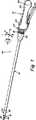
図1は、本発明の外科用器具10の1つの好ましい実施の形態の斜視図である。この外科用器具において、ツール及びハンドルの動き部材又は曲げ可能な部材の双方は、任意の方向に曲げることができる。これらの部材は、基端部材における曲げ動作が末端部材における関連した曲げとなるような態様にてケーブルを介して相互に接続される。基端の曲げは、器具のユーザによる制御ハンドルの動き又は偏向によって制御される。換言すれば、外科医は、ハンドルを把持し、器具が図3に示したような位置になったとき、ハンドルにおける動き(偏向)は、直ちに、基端の曲げ可能な部材を制御する一方、該基端の曲げ可能な部材は、ケーブルを介して末端の曲げ可能な部材における相応する曲げ又は偏向を制御することになる。 FIG. 1 is a perspective view of one preferred embodiment of a surgical instrument 10 of the present invention. In this surgical instrument, both the tool and handle movement or bendable members can be bent in any direction. These members are connected to each other via a cable in such a way that the bending action at the proximal member is the associated bending at the distal member. Proximal bending is controlled by movement or deflection of the control handle by the instrument user. In other words, when the surgeon grasps the handle and the instrument is in the position shown in FIG. 3, movement (deflection) in the handle immediately controls the proximal bendable member, while the The proximal bendable member will control the corresponding bending or deflection in the distal bendable member via the cable.
以下に更に詳細に説明するように、基端部材は、向上した人間工学的制御を実現し得るよう末端部材よりも大きいことが好ましい。図2a−2cには、末端の曲げ可能な部材が基端の曲げ可能な部材と同一方向に向けて曲がる曲げ動作が示されている。1つの代替的な実施の形態において、曲げ可能、回転可能又は可撓性の部材は、起動ケーブルを180°回転させることにより反対方向に向けて曲がるよう配置することができ、又は、ケーブルに対する末端及び基端の支持点の間の関係に依存して実際に任意のその他の方向に曲がるよう制御することができる。 As described in more detail below, the proximal member is preferably larger than the distal member so that improved ergonomic control can be achieved. FIGS. 2a-2c show the bending action in which the distal bendable member bends in the same direction as the proximal bendable member. In one alternative embodiment, the bendable, rotatable or flexible member can be arranged to bend in the opposite direction by rotating the activation cable by 180 °, or end to the cable And can be controlled to actually bend in any other direction depending on the relationship between the proximal support points.
末端の曲げ部材にて生じた曲げる動き量は、末端の曲げ可能な部材の寸法と比較した基端の曲げ可能な部材の寸法によって決まることを理解すべきである。開示した実施の形態において、基端の曲げ可能な部材は、末端の曲げ可能な部材の直径の少なくとも2倍であり、その結果、末端の曲げ可能な部材にて生じた動きの程度は、基端の曲げ可能な部材における動きの程度よりも大きい。図2及び図3には、ピッチ運動のみを示す側面図のみが示されているが、基端の曲げ可能な部材は、任意の方向に向けて(約360°)曲げることができ、末端の曲げ可能な部材を同一方向又は反対方向に、但し、同一平面内にて同時に曲がるように制御することができることを理解すべきである。また、図3に示したように、外科医は、軸方向回転ノブ24を回すだけで器具のツールをその長手方向軸線の回りにて任意の向きにて曲げ且つ回すことができる。 It should be understood that the amount of bending motion that occurs at the distal bend member depends on the size of the proximal bendable member compared to the size of the distal bendable member. In the disclosed embodiment, the proximal bendable member is at least twice the diameter of the distal bendable member so that the degree of movement that occurs in the distal bendable member is Greater than the degree of movement in the end bendable member. 2 and 3 only show side views showing only pitch motion, the proximal bendable member can be bent in any direction (about 360 °) It should be understood that the bendable members can be controlled to bend in the same direction or in opposite directions, but simultaneously in the same plane. Also, as shown in FIG. 3, the surgeon can bend and turn the tool of the instrument in any orientation about its longitudinal axis simply by turning the
本明細書では、曲げ可能な部材について説明する。これらの部材については、回転可能な部材又は可撓性の部材として説明することもある。本明細書の説明において、「曲げ可能な部分」、「曲げ可能なセグメント」、「曲げ可能な動き部材」又は「回転可能な部材」のような語は、継手にて枢着された要素と比較して、制御可能に曲げることのできる器具の1つの要素を意味する。本発明の曲げ可能な要素は、一方向に限定されず、任意の方向に曲げることができ、また、任意の方向に向けて容易に曲がる能力を更に特徴とする器具を製造することを可能にする。これらの曲げ可能な動き部材の限定は、制御手段又は被制御手段の何れかとして形成され、また、何ら鋭角な欠損部又は角度を付けること無く、直線から湾曲した形態に変化するよう張力又は圧縮力によって規制することができる器具要素である。 In this specification, the bendable member will be described. These members may be described as rotatable members or flexible members. In the description herein, terms such as “bendable part”, “bendable segment”, “bendable motion member” or “rotatable member” refer to an element pivoted at a joint. By comparison, it refers to one element of an instrument that can be controllably bent. The bendable element of the present invention is not limited to one direction, can be bent in any direction, and makes it possible to manufacture an instrument further characterized by the ability to bend easily in any direction. To do. These bendable motion member limitations are formed as either control means or controlled means, and tension or compression to change from a straight line to a curved form without any sharp defects or angles. An instrument element that can be regulated by force.
図1を参照すると、外科用器具10は、器具の基端におけるハンドル12と、細長い器具の軸14と、外科用器具の末端に配設されたツール又はエンドエフェクタ16とから成っている。ツールは、関節動作式及び非関節動作式ツールを含むが、これらにのみ限定されない多数の異なる形態をとることができる。開示した実施の形態において、器具の軸14は、剛性であり、通常、金属材料にて出来ているが、この器具の軸は、少なくとも部分的に本来的に可撓性又は曲げ可能であるような構造としてもよい。通常の腹腔鏡下外科手術法のため、器具の軸14は、通常、剛性である。腔内手術法にて使用される可撓性の器具の軸の一例として、その内容の全体を参考として引用し本明細書に含めた、2004年4月12日付けで出願された、関連する米国特許出願10/822,081の図14及び図15について説明する。2005年7月20日付けで出願された米国特許出願11/185,911;2005年10月3日付けで出願された米国特許出願11/242,642及び2005年12月14日付けで出願された米国特許出願11/302,654の内容の全体も参考として引用し本明細書に含めてある。 Referring to FIG. 1, a surgical instrument 10 comprises a
図1において、ハンドル12は、2つのハンドル半体12a、12bから成るものとして示されている。器具の軸14の末端におけるエンドエフェクタ16を開閉すべくハンドルを把持するとき、レバー22は、外科医により操作される。図1において、エンドエフェクタは、可動ジョー44と、固定ジョー46とから成るものとして示されている。器具の基端における回転ノブ24を使用して、器具の軸及びエンドエフェクタを回転させる。この回転は、図1にて円形の矢印Rにより示されている。図1にて、座標系はX、Y、Z軸により示されることも分かる。矢印Rで示した器具のロールは、Z軸の回りにて行われる。Z軸は、器具10の軸14の長手方向軸線に相応する。 In FIG. 1, the
図1には、基端の曲げ可能な部材18の一部分を部分的に保持するアダプタカバー26も示されている。器具の軸14の末端には、末端の動き部材又は曲げ可能な部材20が設けられている。図1にて、シース状カバー98により少なくとも部分的に覆われた状態にて示されている。カバー98は、末端の曲げ可能な部材がハンドルを介して基端の曲げ可能な部材から起動されるとき、容易に偏向する薄いプラスチック又はゴム製の可撓性管とすることができる。針ホルダ又は縫合支援装置のような器具の場合、順応性カバー98は、結び目を結ぶ間、縫合材が引っ掛るのを防止する点にて有益である。しかし、その他の用途の場合、器具及びその製造を簡単にするため、カバー98を使用しないことを選んでもよい。ノブ24、アダプタカバー26及び曲げ可能な部材のようなその他の構成要素は、プラスチック材料にて形成されることが好ましい。 Also shown in FIG. 1 is an
本発明の器具は、使い捨て型とし又はこれと代替的に、再使用再処分可能であるような構造とされることが好ましい。従って、器具を可能な限り経済的であるようにするため、構成要素の殆どはプラスチック材料にて出来ている。 The device of the present invention is preferably disposable or alternatively structured to be reusable and redisposable. Therefore, in order to make the instrument as economical as possible, most of the components are made of plastic material.
図2A−2Cには、ハンドル及びエンドエフェクタが同一方向に回転し又は曲がるよう制御される、外科用器具の1つの実施の形態が示されている。ハンドルを上方に回したとき、ツールは、上方に回転し、その逆に下方に回したとき、ツールは下方に回転する。図2Aには、ハンドルが真直ぐな位置にあり、相応するツールが同様に真直ぐな位置にある状態が示されている。図2Bには、矢印Aの方向に向けて上方に動かした器具のハンドル端部が示されている。これにより、エンドエフェクタ16は、矢印Bの方向に向けて下方へ相応する動きを生じさせる。同様に、図2Cには、ハンドル12を矢印Cの方向に向けて下方に動かして、エンドエフェクタ16の相応する矢印Dの方向に向けた上方への動きを生じさせる状態が示されている。図2B及び図2Cに示した曲げ力は、ハンドル12から基端の曲げ可能な部材18に加えられ、また、基端の曲げ可能な部材を曲げ又は回転させるとき、この力は、末端の曲げ可能な部材に相応する曲げ又は回転を生じさせ、エンドエフェクタの位置及び向きを制御することができる。曲げ力は、外科医がハンドルを所望の方向に向けて動かすことにより器具のハンドルに加えられ、また、基端の曲げ可能な部材に伝達され、更に、末端の曲げ可能な部材に伝達される。また、図2A−2Cには、図面の実質的に平面内にて「上方」及び「下方」への動きのみが示されているが、ハンドルは、図面の面内面外の平面を含む、任意の方向(約360°)に向けて起動させることが可能であることが理解される。 2A-2C illustrate one embodiment of a surgical instrument where the handle and end effector are controlled to rotate or bend in the same direction. When the handle is turned upward, the tool rotates upward, and conversely when it is turned downward, the tool rotates downward. FIG. 2A shows the handle in a straight position and the corresponding tool in a straight position as well. 2B shows the handle end of the instrument moved upward in the direction of arrow A. FIG. As a result, the
図3には、外科的方法を実施する間に見られるような位置にある外科用器具10が示されている。例えば、器具は、腹壁4を通じての腹腔鏡下外科手術法のため使用することができる。この目的のため、カニューレ又はトロカール8が配設される挿入箇所6が提供される。器具14の軸は、カニューレ8を通過し、器具の末端を手術箇所に配設し得るようにされている。エンドエフェクタ16は、図4にてかかる手術箇所で示されている。図3には、また、本発明の器具にて実行することのできるローリング動作も示されている。このローリング動作は、回転ノブ24を実質的にハンドルの長手方向中心線である軸線Tの回りにてハンドル12に対して回転させることにより行うことができる。これは、図3に円形の矢印R1で示されている。回転ノブ24を何れかの方向に回したとき、これは、器具の軸14に相応する回転を生じさせる。これは、図3に回転矢印R2で示されている。この同一の動きは、図3に回転矢印R3で示したように、軸線Pの回りにてエンドエフェクタ16の回転も生じさせる。図3にて、ハンドル12は、基端の曲げ可能な部材18を介して器具の軸の長手方向中心軸線に対し角度B1で軸線Tに沿って傾動した状態で示されている。この傾動、偏向又は曲げは、図面の面内にて行なわれるものと考えることができる。ケーブルにより、この動作により末端の曲げ可能な部材20にて相応する曲がりが生じ、先端は、軸線Pに沿って且つ、器具の軸の長手方向中心軸線に対し角度B2で向けられた位置に達する。この基端の曲げ可能な部材は、該部材をハンドルと接続することにより制御され、このため、ハンドルの動きによって基端の曲げ可能な部材が制御される一方、末端の曲げ可能な部材も制御される。 FIG. 3 shows the surgical instrument 10 in a position as seen while performing a surgical method. For example, the instrument can be used for laparoscopic surgical procedures through the abdominal wall 4. For this purpose, an insertion point 6 is provided in which a cannula or
曲げ可能な部材を介しての操作と、ノブ24を介しての回転とを組み合わせることは、外科医にとって極めて精密で且つ人間工学的に快適な程度の制御を実現することになる。器具は、使用する間、多数の異なる仕方にて保持し得るようにされている。1つの技術において、器具ハンドルを把持して、親指がレバー22と係合し且つボタン96を解放する間、中指、薬指、小指が表面12cの回りに位置するようにすることができる。人指し指は、回転ノブ24と係合するよう伸びるようにする。このようにして、全ての操作は、外科医が片手にて容易に協調させることができる。器具は、次のような仕方にて把持してもよい。すなわち、複数の指がレバー22を把持する間、親指が表面12c上に休止するようにする。人指し指にてノブ24を操作する。親指はノブ24の操作を助けることもできる。 The combination of manipulation through the bendable member and rotation through the
図面には、1組みのジョーが示されているが、本発明の器具と共にその他のツール又は装置が容易に使用できるようにされている。これらは、カメラ、検出器、光学素子、スコープ、流体送り出し装置、注射器等を含むが、これらにのみ限定されるものではない。ツールは、ジョー、鋏、捕捉器具、針ホルダ、小型切開器、ステープルアプライヤー、タッカー、吸引洗浄ツール及びクリップアプライヤーのような多岐にわたる関節接続式ツールを含むことができる。更に、ツールは、切除ブレード、プローブ、洗浄器、カテーテル又は吸引オリフィスのような非関節接続式ツールを含むことができる。 Although a set of jaws is shown in the drawings, other tools or devices can be readily used with the instrument of the present invention. These include, but are not limited to, cameras, detectors, optical elements, scopes, fluid delivery devices, syringes, and the like. Tools can include a variety of articulated tools such as jaws, scissors, capture devices, needle holders, small incisors, staple appliers, tuckers, suction irrigation tools and clip appliers. In addition, the tools can include non-articulated tools such as ablation blades, probes, irrigators, catheters or suction orifices.
次に、図1に示した器具10の更なる詳細のため、図4−図8を参照する。この特定の実施の形態において、器具の軸内のケーブルは、図5に示したような真直ぐな形態にて示され、また、図6には曲げた状態が示されている。エンドエフェクタ又はツール16は、主として、器具の基端にて細長いレバー22から成るジョー起動手段によって起動される。レバー22は、レバー枢着ピン23にてハウジングから支持されている。図4−図6を参照。レバー22をハンドル12に対して閉じることは、スライダ28に作用し、このスライダは、起動ケーブル38の最基端を捕捉すべく使用される。レバー22が非起動状態とされたとき(ハンドルハウジングから分離された状態)、これは、エンドエフェクタのジョーが完全に開いた位置にあることに相応する。レバー22が閉じると、これによりスライダ28は、図5に示したように、右方向に向けて動き、次に、ジョー44、46は、閉じた位置に向けて動かされる。図5にて、ジョーは、例えば、針45を把持し得るよう閉じた状態で示されている。 Reference is now made to FIGS. 4-8 for further details of the instrument 10 shown in FIG. In this particular embodiment, the cable in the instrument shaft is shown in a straight configuration as shown in FIG. 5, and FIG. 6 shows the bent state. The end effector or
器具の軸14は、軽金属材料にて製造することができ、又はプラスチック材料とすることができる外側軸管32を含む。管32は、特に、器具を腔内手術法にて使用し得るよう、本来的に可撓性である構造とすることもできる。管32の基端は、アダプタカバー26により受け入れられる。管32の末端は、末端の曲げ可能な部材20に固定される。末端の曲げ可能な部材20の幾つかの更なる詳細のため、図6を参照する。外側軸管32内にて、プラスチック材料から製造されることが好ましい支持管34が提供される。管34は、末端の曲げ可能な部材又は可撓性部材20と基端の曲げ可能な部材又は可撓性部材18との間を伸びている。ジョーアクチュエータケーブル38はこの支持管34内を伸びる。支持管34は、その長さに沿って複数のスペーサ(図示せず)を支持することができる。スペーサの各々は均一に隔てられ且つ、ケーブルに対する直径方向案内スロットを設けることができる。 The
次に、器具のツール端の更なる詳細のため図5及び図6も参照する。エンドエフェクタ16は、1対のジョー44、46から成っている。上述したように、これらのジョーは、針45又はその他の物品を把持するため使用することができる。上側ジョー44は下側ジョー46のチャンネル内に嵌合している。枢着ピン48がジョーの間に使用されて、その両者間の回転を可能にする。並進ピン42がジョーのスロットを通って伸び且つ、ジョーアクチュエータケーブル38と係合する。レバー22がその休止位置にあるとき、ジョーは完全に開いている。この位置において、ピン42はより末端の位置にあり、ジョーを開いた位置に維持する。ケーブル38が引っ張られると、そのとき、ピン42はスロット内にて右方向に動き、ジョー44、46が図5に示した閉じた位置に向けて回動するようにする。 Reference is now also made to FIGS. 5 and 6 for further details of the tool end of the instrument. The
図5には、ジョー46の基部壁54も示されている。末端の曲げ可能な部材20の一端はこの端部壁54にて支持されている。部材20は、適正な手段により壁54に対し固定することができる。基部壁54に隣接して、末端の曲げ可能な部材20の端部ディスク110aが設けられている。図11も参照。端部ディスク110aは、撓み制御ケーブル100に対するアンカーを支持する。図8には、かかる4つのケーブル100a、100b、100c、100dが示されている。 Also shown in FIG. 5 is the
ジョーアクチュエータケーブル38は、それぞれの端部がエンドエフェクタ及び回転バレル66にて終わる(図5参照)。曲げ可能な部分又は曲げ可能な部材18、20の各々内には、プラスチック管が設けられている。このプラスチック管は、末端管60と、基端管62とを含む。これら管又はシースの双方は、ポリエチルエーテルケトン(PEEK)のようなプラスチックにて製造することができる。管60、62の材料は、ケーブル38を保持するのに十分剛性であり、しかも、曲げ可能な部材18、20の曲がりと共に容易に曲がるよう十分に可撓性である。管は、ケーブルを受け入れ且つ案内するのに十分な強度を有し、しかも捩れたり変形せず、これによりケーブルを起動のため適正な状態に保ち且つケーブルに対する一定の長さを画するのに十分可撓性である。管60、62は、長手方向に剛性であるが、側方向には可撓性である。 Each end of the
エンドエフェクタ16の制御は、ジョーアクチュエータケーブル38によって行われる。上述したように、ジョーアクチュエータケーブル38の最基端は、回転バレル66内にて保持される。例えば、図5に示したように、ケーブル38は回転バレル66に固定される。回転バレル66はスライダ28内にて支持されている。スライダ28には、空所から伸び且つリンク70を受容するスロット74も設けられている。リンク70は、スライダ28を、また、アクチュエータケーブル38をレバー22から起動させる主要な手段である。 The
起動リンク70は、一端にて枢着ピン71によってレバー22から支持されている。リンク70の他端は、本明細書にてスライダピン72として説明した別のピンにて支持されている。ピン72は、スライダ28のスロット74内にて長手方向に動くよう保持されている。図5には、リンク70の他端におけるそれぞれのピン71、72が示されている。図5には、アクチュエータばね76に対して押し付けられたスライダピン72も示されている。ばね76は、スライダ28の区画内に配設されている。アクチュエータばね76の他端は、ばね76を受容するボア内に配設された保持ピン80によって保持されている。図5には、ばね82を受容し得るようハンドルのボア内に配設された戻りばね82も示されている。ばね82の一端は、ハンドルの内壁に押し付けられ、ばねの他端は、スライダ28の端部壁に押し付けられる。ばね76は、ばね82よりも強力なばねであり、レバー22が起動されたとき、ばね82が最初に圧縮するようにすることが好ましい。次に、レバーの追加的な動きにより、物品を把持したとき、ばね76は圧縮される。この二重のばねの配置は、レバーの動作によって加えられた過剰な力に起因する、特に器具の末端における器具のケーブルの損傷を防止することになる。 The
レバー22は、該レバーがハンドル本体に向けて押されたとき、エンドエフェクタを起動する。レバー22は、ラチェット及び爪装置によって作動し、レバーは、ラチェットによる漸増量だけ押すことができる。このラチェット及び爪装置は、ラチェット86と、爪88とを含む。ラチェット86を受容するため、スライダ28には、端部くぼみ又は切欠きが設けられる。爪88は、ハンドル部材12a、12bによって保持される。この点に関して、ハンドル部分12aには、爪88に対する空所があり、また、ハンドル部分12bには、爪を保持する脚部が設けられる。ラチェット88は、枢着ピン90にて回動し且つ、一連のラチェット歯が設けられており、これら一連のラチェット歯は、エンドエフェクタが連続的に閉じる程度に相応する連続的な位置にてラチェットを保持することができる。捩りばね92が枢着ピン90の回りにて部分的に配設され且つ、ラチェット歯を押して爪88と接触させる。 The
ラチェット及び爪装置は、通常、外科医の親指が係合可能な一体的な解放手段を含む。図5に示したように、枢着ピン90の一側部に爪86があり、また、枢着ピンの反対側にアーム94がある。解放ボタン96は、アーム94の基部にて形成されている。力が図5の矢印Mの方向にボタン96に対して加えられたとき、この力は、ラチェット及び爪装置を解放し且つ、レバー22をジョーが完全に開いたその解放位置に戻す。ボタン96を押すと、ラチェット86は回転して爪88との係合から脱する。 Ratchet and nail devices typically include integral release means that can be engaged by the surgeon's thumb. As shown in FIG. 5, there is a
次に、基端及び末端の曲げ可能な部材の間を伸びるケーブルに関して説明する。このケーブルは、基端の曲げ可能な部材における全ての曲がりが末端の曲げ可能な部材における相応する曲げに変換されるよう提供される。基端の曲がりによってケーブルは一側部にて緊張し、反対側部にて弛緩する。本明細書にて説明した曲げ可能な部材は、全方向への曲がりを可能にする。本明細書にて説明した好ましい実施の形態にて、末端の曲げ可能な部材は、図3−5に示したように、基端の曲げ可能な部材の直径の約1/2である。しかし、上述したように、器具の特定の用途及び器具を使用する医学的法に依存して、その他の直径関係を使用することができる。 Next, the cable extending between the proximal and distal bendable members will be described. This cable is provided so that all the bends in the proximal bendable member are converted into corresponding bends in the distal bendable member. The bending of the proximal end causes the cable to be tensioned on one side and relaxed on the opposite side. The bendable members described herein allow bending in all directions. In the preferred embodiment described herein, the distal bendable member is about ½ the diameter of the proximal bendable member, as shown in FIGS. 3-5. However, as noted above, other diameter relationships can be used depending on the particular application of the instrument and the medical method in which the instrument is used.
基端の曲げ可能な部材18と末端の可撓性部材との間の制御は、可撓性の制御ケーブル100によって実行される。例えば、図8にて、識別した図示する実施の形態において、ケーブル100a、100b、100c、100dのような、かかる4つのケーブルがある。上述したように、これらケーブルの末端にて、ケーブルは、最末端のディスク110にてアンカーと接続する。ケーブル100は、その基端にてケーブル端部の耳状突起102により保持されている。4つのばね104がこれらの端部の耳状突起102とハブ101の壁との間にて保持されている。端部の耳状突起102及びばね104の図について図5を参照。ばね104は、緊張し又はケーブルの弛みをとる。曲げ可能な部材の間にて、ケーブル100は、支持管34に沿って配設することのできるスペーサ(図示せず)のスロットにより案内することができる。アダプタカバー26内にて、ケーブル100は、転位部材106を貫通して伸びている。次に、ケーブルは、図5及び図6に示したように、基端の曲げ可能な部材を貫通して伸びるとき、より大きい外径位置まで伸びる。段付きの転位部材106は、金属製とすることができ、また、管34の端部に隣接する位置に配設される。 Control between the proximal
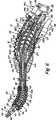
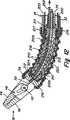
図5及び図6には、器具の末端、特に、末端の可撓性部材20が示されている。この部材は、一連のディスク又はディスク要素110から成る相互係止型のディスク装置の形態をしており、これらのディスク又はディスク要素は、半球形の形態をしており且つ、互いに入れ子式に嵌まり、また、次々と相互に係合し得るようにされている。図11も参照。これらディスクの各々は、ケーブルの所望の位置に相応して90°の間隔にて配置された、起動ケーブル100を受け入れる穴を有している。これらのディスクは、反対端のディスク110a、110bも含む。図6には、端部ディスク110bを貫通するケーブル100が示されている。他端ディスク100aは、アンカーにてケーブル端部を支持している。軸受112がエンドエフェクタ16の基部壁54と端部ディスク110aとの間に配設されている。この軸受は、エンドエフェクタ16がディスク110に対し容易に回転することを可能にする。第二の軸受114も端部ディスク110bに設けられて、端部ディスク110bと外管32との間の回転を可能にする。このように、外管32は、エンドエフェクタと共に、回転ノブ24から回転可能である一方、内管60、ケーブル100及びディスク110は、回転不能である。末端の曲げ可能な部材20は、基端の曲げ可能な部材に対する図7に示したものと同様に、各ディスクの中心穴を通って伸びる、上述したPEEK管60を受け入れる。 5 and 6, the distal end of the instrument, in particular the distal
末端の動き部材20は、対向端にて外管32及び基部壁54に装着された外側ベローズ116も含む。スリーブ117を使用してベローズ116を管32に装着することができる。同様のスリーブ118を使用してベローズ116の他端を基部壁54に装着することができる。図11も参照。外側器具の管32に加えられた全ての回転は、ベローズ116を介してエンドエフェクタ16に連結される。このように、器具が回転する間、静止状態に維持され、また、内側ディスク、ケーブル及び内側スリーブを含む内側器具部分がある。これと同時に、内側器具部分に対し回転することができ、また、外側スリーブ、ベローズ及びエンドエフェクタを含む、外側器具部分がある。 The
基端の動き部材18は、末端の動き部材と同様の態様にて製造されており、また、一連のディスク120を含み、これら一連のディスクは、半球形の形態をしており、また、互いに入れ子式に嵌合し且つ、次々と相互に係合し得るようにされている。これらディスクの各々は、ケーブルの所望の位置に相応する90°の間隔にて配置された、起動ケーブル100を受け入れる穴を有している。これらのディスクは、対向した端部ディスク120a、120bも含む。図6及び図7には、端部ディスク120aを貫通するケーブル100が示されている。他端のディスク120bは、ハンドル12内に固定されたハブ101と係合する。軸受又はブッシュ122がハブ101と回転ノブ24との間に配設されている。この軸受122は、回転ノブ24がハブ101に対して容易に回転することを可能にする。第二の軸受又はブッシュ124もアダプタ26に設けられて、転位部材106とアダプタ26との間の回転を可能にする。外管32は、アダプタと共に、回転ノブ24から回転可能である一方、内管62、ケーブル100及びディスク120は、回転不能である。ケーブル100は、その基端にてケーブル端部の耳状突起102により保持されている。4つのばね104がこれらの端部の耳状突起102とハブ101の壁との間に保持されている。端部の耳状突起102及びばね104の図について図6及び図7を参照。ばね104は、緊張し又はケーブルの弛みをとる。末端の曲げ可能な部材18は、各ディスクの中心穴を貫通して伸びる上述したPEEK管62を受け入れる。 The
基端の動き部材18は、両端にてアダプタ26及び回転ノブ24に装着された外側ベローズ126も含む。スリーブ127を使用してベローズ126をアダプタ26に装着することができる。同様のスリーブ128を使用してベローズ126の他端を回転ノブ24に装着することができる。回転ノブ24に与えられた全ての回転は、ベローズ126を介してアダプタ及び器具の軸に結合され、そこから、器具の末端に結合されてエンドエフェクタを回転させる。このように、器具が回転する間、静止状態に維持され、また、内側ディスクと、ケーブルと、内側スリーブとを含む器具の基端内側部分がある。これと同時に、内側器具部分に対して回転することができ、また、外側スリーブと、ベローズと、回転ノブとを含む外側器具部分がある。 The
図4から図8に示した実施の形態は、基端及び末端の動き部材間の位置を図6に示した位置のような所望の位置に固定することを可能にする係止特徴部を含んでおり、この位置にて、ハンドルは、下方に曲げられ、ツールはこれに相応して上方に曲げられる。図6において、頂部ケーブルは、緊張されて、また、底部ケーブルは弛緩している。外科医が所望の曲がった位置に器具を有するとき、次に、係止部材を使用し器具をその位置に便宜に保持する。係止部材は、枢着ピン142によりハンドルから回動可能に支持された係止レバー140として図5及び図6に示されている。図1−図3の係止レバー140も参照。図5には、その解放位置にある係止レバー140が示されており、この位置にて、曲げ可能な部材は、係止されることなく、器具の通常の操作のとき、曲がることが許容される。 The embodiment shown in FIGS. 4-8 includes a locking feature that allows the position between the proximal and distal movement members to be secured in a desired position, such as the position shown in FIG. In this position, the handle is bent downwards and the tool is correspondingly bent upwards. In FIG. 6, the top cable is tensioned and the bottom cable is relaxed. When the surgeon has the instrument in the desired bent position, the locking member is then used to conveniently hold the instrument in that position. The locking member is shown in FIGS. 5 and 6 as a locking
この係止特徴は、所望の位置となったとき、外科医が器具を係止することを可能にする、器具のその他の制御機能に付随する1つの重要な点である。このことは、外科医が同時に、器具を特別な曲がった形態にて保持することを必要とせずに、その後、外科的方法を行なうことをより容易にする。相対的に回転可能な内側及び外側器具部分は、外科医が係止状態にて回転ノブを使用して末端のエンドエフェクタの長手方向軸線の回りにて回転するようエンドエフェクタを制御することを可能にする。また、係止レバー又は同様の係止機構を直接、ユーザの手の届く範囲内にてハンドルに有することにより、片手で器具を制御する効果的で且つ便宜な方法が提供される。 This locking feature is one important point associated with the other control functions of the instrument that allow the surgeon to lock the instrument when in the desired position. This makes it easier for the surgeon to subsequently perform the surgical procedure without having to hold the instrument in a special bent configuration at the same time. The relatively rotatable inner and outer instrument portions allow the surgeon to control the end effector to rotate about the longitudinal axis of the distal end effector using the rotary knob in the locked state. To do. Also, having a locking lever or similar locking mechanism on the handle directly within reach of the user's hand provides an effective and convenient way to control the instrument with one hand.
このように、ハンドルの制御装置を使用して、器具を基端の曲げ可能な部材にて曲げる一方、末端の曲げ可能な部材及びツールの位置を制御する。ツールの「位置」は、主として、この曲げ動作により決まり、また、末端の曲げ可能な部材の末端における座標位置とみなすことができる。この位置は、三次元的である。他方、ツールの「向き」は、図示した末端の先端の軸線の回りにおけるツールの回転位置を意味する(図3の軸線Pを参照)。 In this way, the handle control device is used to control the position of the distal bendable member and tool while the instrument is bent at the proximal bendable member. The “position” of the tool is mainly determined by this bending action and can be regarded as the coordinate position at the end of the end bendable member. This position is three-dimensional. On the other hand, the “orientation” of the tool means the rotational position of the tool around the axis of the tip of the end shown in the figure (see axis P in FIG. 3).
実際に、係止部材の多数の異なる実施の形態について本発明を説明する。第一の実施の形態において、係止部材140は、図4−図8に示したように、基端の曲げ可能な部材を係止することにより、器具の位置を係止する。基端の曲げ可能な部材が係止されたとき、この部材は、ケーブルの位置を一定の位置に維持し、また、末端の曲げ可能な部材に対して係止位置を維持する。図9に示し且つ以下に更に詳細に示す別の実施の形態において、係止部材は、基端の曲げ可能な部材ではなくて、末端の曲げ可能な部材を係止する。しかし、この実施の形態において、末端の曲げ可能な部材を係止することは、基端の曲げ可能な部材を一定の位置に維持することにもなる。図10に示したような本発明の更に別の実施の形態において、基端の曲げ可能な部材を係止するための1つの係止部材、及び末端の曲げ可能な部材を係止するためのもう一方の係止部材という、別個の係止部材が設けられ、このため、双方の曲げ可能な部材は確実に且つ別個に係止される。 Indeed, the present invention will be described with respect to a number of different embodiments of locking members. In the first embodiment, the locking
図4−図8の実施の形態において、係止レバー140には、係止レバーを図5に示したような非係止位置に通常、維持することを可能にする保持装置が設けられる。説明した保持装置は、係止レバー140における突起144と、ハンドルの凹所145とを含む。係止レバー140は、ばね146により図5に示した位置に偏倚される。係止ケーブル150がプーリー152の回りを伸び且つ一端にてばね146にて固定されている。ケーブル150の他端は、端部ディスク120aの末端面の箇所154にて終わる。図5に示した位置において、ケーブル150は弛緩しており、このため、端部ディスクをその他のディスクに対し係止するため端部ディスク120aに力が加えられることはない。従って、図5の係止レバー140の位置において、基端の曲げ可能な部材は、曲げ且つ偏向自在であり、末端の曲げ可能な部材を制御する。 In the embodiment of FIGS. 4-8, the locking
基端の曲げ可能な部材の係止状態は図6に示されており、この場合、係止レバー140は、矢印141の方向に向けて動かされて、レバーをピン142の回りにて回動させ且つ、レバー140における突起144をハンドルの凹所145と係合させる。この動作は、係止レバー140を図6に示した位置に維持することになる。この動作は、ケーブル150を引っ張り、これにより端部ディスク120aに締結力を提供する。この締結力は図6にて矢印155で示されている。この締結動作は、基端の曲げ可能な部材を備えるその他の連続的なディスク120の全てに対して端部ディスク120aを矢印155の方向に押し付ける。この動作は、係止レバーが押されたときに生じるように、曲がり部を基端の曲げ可能な部材の特定の位置に確実に係止することになる。基端の曲げ可能な部材が特定の位置に係止された状態のとき、このことは、末端の曲げ可能な部材を図6に示した曲がった位置のようなその相応する位置にも維持することになる。曲がり制御ケーブルは同一の長さであるから、相応する同一の位置に末端の曲げ可能な部材を保持する基端の曲げ可能な部材が係止され、また、基端の曲げ可能な部材が特定の位置にて固定されたとき、このことは、末端の曲げ可能な部材をその相応する一定の位置に保持することになる。 The locking state of the proximal bendable member is shown in FIG. 6, where the locking
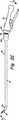
図4−図8に示した器具の操作を更に説明するため、図7A及び図7Bも参照する。図7Aには、外側器具部分のみが示されている一方、図7Bには内側器具部分が別個に示されている。外側器具部分は、外側シース組立体として説明する一方、内側器具部分は、内側アーマチャー組立体として説明することもある。外側シース組立体は、回転ノブ24を介してエンドエフェクタを回転させ、また、基端及び末端のベローズを介して三次元的に又は三軸線内にて曲げ又は撓むことを可能にする。内側アーマチャー組立体は、ハンドル12からのケーブルを介してディスク110、120の間にて曲げ動作を提供する。図7Aの外側シース組立体は、器具の基端から末端まで、回転ノブ24と、ベローズ126と、外管32と、ベローズ116と、ツール16とを含む。図7Bの内側アーマチャー組立体は、器具の基端から末端まで、ハンドル12と、基端の曲げ可能なディスク120と、内管34と、末端の曲げ可能なディスク110とを含む。図7Aには、基端の軸受122、124と末端の軸受112、114の位置も示されている。図7Bには、参照番号113、123にて相応する軸受の位置も示されている。 To further illustrate the operation of the instrument shown in FIGS. 4-8, reference is also made to FIGS. 7A and 7B. In FIG. 7A, only the outer instrument portion is shown, while in FIG. 7B, the inner instrument portion is shown separately. The outer instrument portion is described as an outer sheath assembly, while the inner instrument portion may be described as an inner armature assembly. The outer sheath assembly allows the end effector to rotate through the
図7Aには、本発明の器具にて実行することができるローリング動きも示されている。これは、回転ノブ24が実質的にハンドルの長手方向中心線である軸線Tの回りにてハンドル12に対して回転することにより生ずる。この状態は、円形の矢印R1で図7Aに示されている。回転ノブ24が何れかの方向に回転したとき、これによって回転矢印R2により図7Aにて示した器具の軸の相応する回転が生ずる。この同一の動きにより、エンドエフェクタ16は図7Aにて回転矢印R3で示したように軸線Pの回りで回転する。図7Bにおいて、ハンドル12は、基端の曲げ可能な部材を介して、軸線Tに沿って器具の軸の長手方向中心軸線に対して角度B1で傾動し、器具の末端にて角度B2で傾動するようにする状態が示されている。 Also shown in FIG. 7A is a rolling motion that can be performed with the instrument of the present invention. This is caused by the
次に、係止部材が基端の曲げ可能な部材ではなく、末端の曲げ可能な部材を係止する、本発明の代替的な実施の形態について図9を参照する。図9は、係止レバー240として図9に識別した係止部材を採用する外科用器具の長手方向側面図である。図9において、図4−図8に示した器具の部品と実質的に同一である、器具の部品を識別するため同一の参照番号が使用されている。このように、図9の器具は、ハンドル12と、レバー22と、回転ノブ24と、器具の軸14を介して末端の曲げ可能な部材20と接続された基端の曲げ可能な部材18とを備えている。エンドエフェクタ16は、器具の最末端にて支持されている。 Reference is now made to FIG. 9 for an alternative embodiment of the present invention in which the locking member locks the distal bendable member rather than the proximal bendable member. FIG. 9 is a longitudinal side view of a surgical instrument employing the locking member identified in FIG. 9 as the locking
図9に示した実施の形態と図4から図8に示した実施の形態との主要な相違点は、係止部材240が器具の最末端に連結されたケーブル250を起動させて、基端の曲げ可能な部材ではなくて、末端の曲げ可能な部材20を係止する点である。係止レバー240は、図5及び図6に示したものと同一でよく、また、レバー部材240の対向した位置での回動を可能にすべく保持部及びばね装置を含む。図9には、端部254におけるケーブル250の最末端も示されている。レバー部材240が矢印242の方向に回動されたとき、このレバー部材は、ケーブル250を図9の右方向に引っ張り、また、図9にて矢印255で示したように引っ張り力が器具の末端に加えられる。これにより最末端のディスク部材110aは、その他の連続的なディスク部材と確実に係合し、末端の曲げ可能な部材を所定の位置に係止する。末端の曲げ可能な部材が特定の位置にて係止された状態にて、このことは、基端の曲げ可能な部材を図6に示したような曲がった位置のようなその相応する位置にても維持することになる。末端の曲げ可能な部材は、係止レバーが起動されたとき、該部材が配設される特定の位置に係止される。 The main difference between the embodiment shown in FIG. 9 and the embodiment shown in FIGS. 4 to 8 is that the locking
次に、1対の係止部材が採用される、本発明の更なる実施の形態について図10を参照する。これらは、図10にて係止レバー140、240として識別されている。図10は、曲げた位置にある器具を示す長手方向断面図であり、この場合、基端の曲げ可能な部材は、角度B1だけ偏向されて、器具の末端をエンドエフェクタにて角度B2だけ同様に偏向させる。 Reference is now made to FIG. 10 for a further embodiment of the invention in which a pair of locking members are employed. These are identified as locking
このように、図10及び図11に示した実施の形態において、各々、個別に操作可能であり、又は、並行に操作可能である2つの別個の係止レバーがある。係止レバー140は、ケーブル150を制御する一方、該ケーブルは、箇所154にて基端の曲げ可能な部材の係止を制御する。係止レバー240は、器具の末端まで伸びるケーブル250を制御し、該ケーブルは、箇所254にて末端の曲げ可能な部材20の係止を制御する。図10にて、係止レバー240は、係止状態で示される一方、係止レバー140は、非係止状態で示されている。 Thus, in the embodiment shown in FIGS. 10 and 11, there are two separate locking levers that can each be operated individually or in parallel. The locking
図10にて、2つの係止レバーは、それぞれの基端及び末端の部材の係止を別個に制御するものとして示されている。従って、個々の係止レバーは、それらのそれぞれの曲げ可能な部材のみを制御する。1つの代替的な実施の形態において、係止レバー140、240は、ケーブル150、250の双方を同時に制御する単一のレバーとして形成することができる。このように、単一の係止レバーが起動されたとき、該レバーは、基端及び末端の曲げ可能な部材の双方を係止する。 In FIG. 10, the two locking levers are shown as separately controlling the locking of the respective proximal and distal members. Thus, the individual locking levers control only their respective bendable members. In one alternative embodiment, the locking levers 140, 240 can be formed as a single lever that controls both
図11は、拡大断面図にて多少更なる詳細を示す、器具の末端の断面図である。この図には、端部ディスク110aまで伸びるケーブル250が示されており、該ケーブルは、引っ張って最末端のディスク110aを隣接するディスク110に押し付けることができる。一方、箇所254におけるこの動作により、末端の曲げ可能な部材を備えるディスクの各々は、相互に係合し、このため、末端の曲げ可能な部材を特定の曲げた状態にて係止する。図11には、また、制御ケーブル100及びツールの起動ケーブル38も示されている。 FIG. 11 is a cross-sectional view of the distal end of the instrument showing some additional details in an enlarged cross-sectional view. In this figure, a
基端の曲げ可能な部材18と、末端の可撓性の部材20との間の制御は、可撓性の制御ケーブル100にて行われる。例えば、図8にて識別した図示する実施の形態にて、ケーブル100a、100b、100c、100dとしてかかる4つのケーブルがある。上述したように、これらケーブルの末端にて、ケーブルは、最末端のディスク110にてアンカーと接続する。ケーブル100は、その基端にてケーブル端部の耳状突起102により保持されている。4つのばね104がこれらの端部の耳状突起102とハブ101の壁との間にて保持されている。端部の耳状突起102及びばね104の図について、図5を参照。ばね104は緊張し又はケーブルの弛みをとる。曲げ可能な部材の間にて、ケーブル100は、支持管34に沿って配設することのできるスペーサ(図示せず)のスロットにより案内することができる。アダプタカバー26内にて、ケーブル100は、転位部材106を貫通して伸びている。その後、ケーブルは、図5及び図6に示したように、基端の曲げ可能な部材を貫通して伸びるとき、より大きい外径位置まで伸びる。段付きの転位部材106は、金属製とし且つ、管34の端部に隣接する位置に配設される。 Control between the proximal
次に、図12−15に示した本発明の更なる実施の形態について説明する。本明細書に記載した上述の実施の形態において、曲げた制御ケーブル100は、回転不能であり且つ、内側器具部分の一部を形成する。図12−15に示した実施の形態において、制御ケーブル200は、器具の基端及び末端の双方にてベローズを通して配置され、また、回転ノブ24、器具の軸14及びエンドエフェクタ16を回転させたとき、回転し得るようにされている。図12−15の実施の形態において、ケーブル150、250をそれぞれ制御するため、2つの係止レバー140、240がある。ケーブル150は、基端の曲げ可能な部材の係止を制御する一方、ケーブル250は、末端の曲げ可能な部材の係止を制御する。 Next, a further embodiment of the present invention shown in FIGS. 12-15 will be described. In the above-described embodiments described herein, the
図12には、器具の末端、特に、末端の可撓性部材及びエンドエフェクタが示されている。これは、半球形の形態をしており、また、次々と相互に係止し得るようにされた一連のディスク又はディスク要素210から成る相互係止式のディスク装置の形態をしている。図12のディスク210は、図11にて上記に示したディスクと多少、異なる構造のものである。これらのディスクの各々は、内側スリーブ260と、スリーブ260内を伸びる起動ケーブル38とを受け入れるテーパー付きの中央通路を有している。これらの末端のディスク210は、対向端のディスク210a、210bも含む。図12には、ディスクを貫通するのではなく、外側ベローズ216の穴を貫通するケーブル200が示されている。このことは、この実施の形態に対するディスクの構造を多少簡単なものにする。 FIG. 12 shows the distal end of the instrument, particularly the distal flexible member and end effector. It is in the form of a hemisphere and is in the form of an interlocking disk device consisting of a series of disks or
一端のディスク210aは、端部壁54に隣接して支持されており、また、他端のディスク210bは、カラー211に隣接して支持されている。軸受又はブッシュ212がエンドエフェクタ16の基部壁54と端部ディスク210aとの間に配設されている。この軸受212は、エンドエフェクタ16がディスク210に対し容易に回転することを可能にする。また、第二の軸受又はブッシュ214が端部ディスク210bに設けられて、カラー211と外管32との間の回転を可能にする。このように、内管260及びディスク210は、回転不能である一方、外管32は、ケーブル、ベローズ及びエンドエフェクタと共に、回転ノブ24から回転可能である。末端の曲げ可能な部材20は、ディスクの各々の中心穴を貫通して伸びる上述したPEEK管260を受け入れる。 The disk 210 a at one end is supported adjacent to the
末端の動き部材20は、両端にて外管32及び基部壁54に装着された外側ベローズ216を有している。スリーブ217を使用してベローズ216を管32に装着することができる。同様のスリーブ218を使用してベローズ216の他端を基部壁54に装着することができる。外側器具の管32に与えられた全ての回転は、ベローズ216を介してエンドエフェクタ16に連結される。このように、器具が回転する間、静止状態に維持される内側器具部分があり、また、該内側器具部分は、内側ディスクと、内側スリーブとを含む。これと同時に、内側器具部分に対し回転することができ、また、外側スリーブと、ベローズと、ケーブルと、エンドエフェクタとを含む外側器具部分がある。 The
基端の動き部材は、末端の動き部材と同様の態様の構造とされており、また、半球形の形態をした一連のディスク220を含み、これら一連のディスクは、次々と相互に係合し得るようにされている。これらディスクの各々は、ツールのアクチュエータケーブル38と、管262とを受け入れる主たるテーパー付き穴を有している。基端及び末端のディスクの双方のテーパーは、ケーブル及び貫通して伸びる管を妨害することなく曲がることを可能にする。これらのディスクは、対向端ディスク220a、220bも含む。図13には、ベローズ226を貫通して伸びるケーブル200が示されている。端部ディスク220bは、ハンドル12内に固定されたハブ201と係合する。軸受又はブッシュ222は、ディスク220aとアダプタ26との間に配設されている。この軸受222は、アダプタ26がディスク220aに対し容易に回転することを可能にする。内管262及びディスク220は、回転不能である一方、外管32は、アダプタ及びベローズと共に、回転ノブ24から回転可能である。ケーブル200は、それらの基端にてケーブルの端部の耳状突起202により保持されている。これらの端部の耳状突起202とハブ201の壁との間に4つのばね204が保持されている。ばね204は緊張し又はケーブルの弛みをとる。末端の曲げ可能な部材は、各ディスクの中心穴を貫通して伸びる上述したPEEK管262を受け入れる。 The proximal motion member is structured in a manner similar to the distal motion member and includes a series of
基端の動き部材は、両端にてアダプタ26及び回転ノブ24に装着された外側ベローズ226を有している。スリーブ227を使用してベローズ226をアダプタ26に装着することができる。同様のスリーブ228を使用してベローズ226の他端を回転ノブ24に装着することができる。回転ノブ24に与えられた全ての回転は、ベローズ226を介してアダプタ及び器具の軸に連結され、また、そこから器具の末端に連結されてエンドエフェクタを回転させる。このように、器具が回転する間、静止状態に維持される基端の内側器具部分があり、該内側器具部分は、内側ディスクと、内側スリーブとを含む。これと同時に、内側器具部分に対し回転することができる外側器具部分があり、該外側器具部分は、外側スリーブと、ベローズと、ケーブルと、回転ノブとを含む。 The proximal movement member has an outer bellows 226 attached to the
図6のベローズ126又は図13のベローズ226のようなベローズを使用する全ての実施の形態において、ケーブルが貫通して伸びるかどうかを問わずベローズ自体がトルク伝達手段として機能することが理解される。換言すれば、ベローズは、回転運動を回転ノブから器具の軸まで伝達するのに十分な剛性を有する。このことは、器具の軸及びエンドエフェクタのような末端の部材まで回転トルクを提供するベローズとして説明することができる。これと同時に、ベローズは、曲げ動作が実行されるとき、撓み(圧縮し又は拡張し)するのに十分可撓性である構造及び配置とされる。例えば、ベローズ126が頂部のより開いた位置に撓んだ状態にて示される一方、底部のより閉じた位置にて撓んだ状態で示される図6を参照。ベローズに対する代替例として、その他の折り畳み可能な部材を使用することもできる。 In all embodiments using a bellows such as the
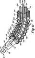
図12−15に示した実施の形態は、基端及び末端の動き部材の間の相対的な位置を図13に示した位置のような特定の位置にて固定することを可能にする係止特徴部を有しており、この場合、ハンドルは下方に曲げられてツールを相応して上方に曲げる。外科医が器具を所望の曲がった位置に有する場合、係止部材を使用して、器具をその位置に保持する。係止部材は、1つ又は別個の枢着ピンによりハンドルから回動可能に支持された係止レバー140、240として図13に示されている。図13には、その係合位置にある係止レバーが示されており、この位置にて、曲げ可能な部材は所定の位置に係止されている。この係止特徴部は、外科医が所望の位置になったとき、器具を係止することを可能にする器具のその他の制御装置に付随する1つの重要な点である。このことは、外科医が同時に器具を特定の曲がった形態に保持することを必要とせずに、外科的手術方法を実行することを一層容易にする。係止状態にあるときであっても、器具の回転は可能である。 The embodiment shown in FIGS. 12-15 is a lock that allows the relative position between the proximal and distal movement members to be fixed in a particular position, such as the position shown in FIG. With a feature, in which case the handle is bent downwards and the tool is correspondingly bent upwards. If the surgeon has the instrument in the desired bent position, a locking member is used to hold the instrument in that position. The locking members are shown in FIG. 13 as locking
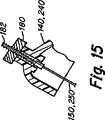
図13−15には、係止レバー140、240からそれぞれ制御される係止ケーブル150、250も示されている。ケーブル150は、端末がディスク220aにて終わる箇所である節又は箇所154にて終わる。ケーブル150を引っ張ると、ディスク220は緊密に係合して曲げ可能な部分を図13に示したような特定の形態に保持する。同様に、ケーブル250は、端末がディスク210aにて終わる箇所である節又は器具の末端の箇所254にて終わる。ケーブル250を引っ張ると、ディスク210は緊密に係合して曲げ可能な部分を図13に示したような特定の形態に保持する。図12−15に示した実施の形態において、係止レバー140、240は、図15の拡大部分図にて示したターンバックル装置によって調節可能である。この装置は、レバーに配置された回転ホイール180を含み、また、該回転ホイールは、係止制御ケーブルのねじ付き端部182を受け入れる内ねじ付き通路を有する。ホイール180を回転させて制御ケーブルに加えられる張力レベルを調節することができる。基端及び末端ディスクの双方にて、最末端ディスクを引っ張ることにより、より基端の全てのディスクに圧力を加え、それらの曲げ可能な部材を図13に示したような特定の曲率に維持することができる。 13-15 also show locking
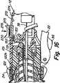
図1−15にて上記に説明した本発明の実施の形態において、係止部材は、回動可能なレバーの形態をしている。しかし、その他の色々な型式の係止部材を採用することができる。これらの係止部材は、ハンドルに又はハンドルに近い位置に取り付け、これらの係止部材が器具のユーザの手の届く範囲に容易に入ることができるようにすることが好ましい。係止部材は、解放位置又は起動位置の何れかとなるよう手操作にて制御可能であることが好ましい。次に、ハンドル12内に適正に取り付けられたスライドスイッチ270の形態をした係止手段の代替的な実施の形態について図16を参照する。スライドスイッチ270は、制御ケーブル151の基端を保持する。制御ケーブル151は、図16にて1対のプーリー152、153上を進むときの状態にて示されている。勿論、制御ケーブル151の末端は、基端又は末端の曲げ可能な部材の何れかに連結することができる。また、別の代替的な実施の形態において、それぞれの基端及び末端の曲げ部材を制御すべく1対のスライドスイッチ270を設けることができる。 In the embodiment of the present invention described above with reference to FIGS. 1-15, the locking member is in the form of a pivotable lever. However, various other types of locking members can be employed. These locking members are preferably attached to the handle or at a position close to the handle so that these locking members can easily be reached within the reach of the user of the instrument. The locking member is preferably controllable by hand so as to be in either the release position or the activation position. Reference is now made to FIG. 16 for an alternative embodiment of locking means in the form of a
図16において、スライドボタン270は、開口部274内にてハンドル12内に支持された状態にて示されている。係止機構には、スライドスイッチ270上の同様のラチェット面と係合し、スライドスイッチ270を選択的に漸増的に配置することを可能にするラチェット面272も設けられている。図16において、スライドスイッチ270は、その解放位置にて示されており、また、開口部274内にて右方向に動いてその係止位置に向けて動くであろう。板ばね275は、スライドスイッチ270内に支持されている。板ばね275は、歯を押して係合状態にさせる。スイッチ270を矢印276の方向に向けて押すと、歯同士の係合は解放され、スライドスイッチはその解放位置まで動くことができる。 In FIG. 16, the
本明細書にて説明した上記の実施の形態において、器具の係止機能を提供し得るように別個の1つ又は複数のケーブルが設けられている。基端の曲げ可能な部材の係止ケーブル及び(又は)末端の曲げ可能な部材の係止ケーブルが採用されている。このように、これらの実施の形態において曲げ制御ケーブル100、200は、曲げ機能のみを果たす。本発明の1つの代替的な実施の形態が図17及び図18に示されており、この実施の形態にて、曲げ制御ケーブルの機能は、曲げ動作のみならず、係止機能をも果たす。これは、全てのケーブルを連動して引っ張って係止機能を実行することにより行われる。これと同時に、係止する間、回転機能は回転ノブ24を通して操作可能である。 In the above-described embodiments described herein, a separate cable or cables are provided to provide a locking function for the instrument. A proximal bendable member locking cable and / or a distal bendable member locking cable are employed. Thus, in these embodiments, the bending
図17及び図18の実施の形態において、図4−8に示した上記の実施の形態にて見られた器具の同様の部分を識別するため、同一の参照符号が使用されている。この実施の形態において、器具は、ハンドル12と、基端の曲げ可能な部材18と、器具の軸14と、末端の曲げ可能な部材20と、エンドエフェクタ16とを備えている。図6に示した実施の形態におけるように、図17にて、ハンドルハウジング内に取り付けられたハブ101に対して回転可能なノブ24も設けられている。器具は、その両者間の相対的な回転を可能にする上述した内側器具部分及び外側器具部分も有している。 In the embodiment of FIGS. 17 and 18, the same reference numerals are used to identify similar parts of the instrument found in the above embodiments shown in FIGS. 4-8. In this embodiment, the instrument includes a
図17には、曲げ可能な部材の偏向を制御すべく使用される4つのケーブル100も示されている。図6の実施の形態において、これらのケーブルは、ハブ101内に固定されている。図17の実施の形態において、これらのケーブルの基端は、解放位置と係止位置との間にて動くことのできるキャリッジ165に固定されている。係止は、器具を特定の曲がった位置にて不動にし又は固定するため、4つの全てのケーブル100を同時に引っ張ることにより行われる。ケーブルを長手方向に引っ張ることにより、図17に矢印170で示した力が加えられ、この力により、末端の曲げ可能な部材のディスクは次々と係止する。この動作は、基端の曲げ可能な部材の位置を相応するよう不動にもする。 FIG. 17 also shows four
図17及び図18の実施の形態において、係止部材は、図6に示したものと同様の、関係した保持装置を有することができる回動可能な係止レバーを備えている。レバー160は、枢着ピン171にて枢着されている。連結機構161は、レバー160からスライダ163に連結する。スライダ163は、図17の断面図にて示したように楔形又はテーパー付きの形状を有しており、また、一側部にて、キャリッジ165の基端164に対して当接する。キャリッジ165は、ハンドルハウジング内に設けられたジャーナル169内にて平行移動し得るようにされている。楔形状のボス175がハンドルに設けられている。キャリッジ165の末端は、4つのケーブル100を支持する板の形態をしている。ケーブルの各々は、該ケーブルと関係した端部の耳状突起167と、ばね又は弾性的なパッド168とを有している。キャリッジには、関係したハンドルスロット内を動くことにより、キャリッジの動きを規制する対向したピン177も設けられている。 In the embodiment of FIGS. 17 and 18, the locking member comprises a pivotable locking lever that can have an associated holding device similar to that shown in FIG. The
図17に示した位置において、キャリッジ165は、その解放位置又は通常の位置にあるものとみなすことができる。このことは、基端の曲げ可能な部材と末端の曲げ可能な部材との間にて何ら係止すること無く、曲げ動作が行われることを許容する。係止レバー160が矢印173の方向に向いて動いたとき、次に、スライダ163は端部164及びボス175に対して当接し、このため、キャリッジ165は、図17にて見たとき、右方向に平行移動する。この動作は、ケーブル100の全てを右方向に引っ張り、これにより矢印170で示したように、器具の末端に力を加えることになる。この力は、基端及び末端のディスク部材の双方をユーザがとった所定の且つ予め選んだ位置にて圧縮することになる。 In the position shown in FIG. 17, the
本発明による外科用器具の別の特徴は、器具が多岐にわたる医学的法に適応し得るようにすることができる点である。このことは、切開又は自然の身体開口を通して体腔にアクセスする等のような、腔内手術法を使用するときの如き体腔へのアクセスを含むが、これにのみ限定されるものではない。外科用器具の解剖学的部位内への導入は、内腔手術法、キャビティ又は血管への経皮的又は外科的アクセス法により、又は、自然のオリフィスを通して解剖学的部位へ導入する方法により行なうこともできる。 Another feature of the surgical instrument according to the present invention is that the instrument can be adapted to a wide variety of medical methods. This includes, but is not limited to, access to body cavities, such as when using intraluminal surgery, such as accessing a body cavity through an incision or natural body opening. Introduction of surgical instruments into the anatomical site is performed by luminal surgery, percutaneous or surgical access to the cavity or blood vessel, or by way of introduction into the anatomical site through a natural orifice. You can also
特に、回動継手又はボールアンドソケット継手のようなその他の機構と異なり、動き部材に対して曲げ可能な部分を採用することにより提供される幾つかの改良点がある。
曲げ可能な部材の第一の重要な性質は、特に、基端のハンドル動き部材に対して使用したとき、その本来的な側方向(曲げ)剛性である。接続した配置において、基端の継手は、切開部の支点と共に、細長い軸と制御ハンドルとの間に配置される。この継手は、「二重継手」として振舞い、継手が「自由」に動くならば器具は、ツールの安定性にとって重大な問題を生じるであろう。執刀外科医は器具の制御ハンドルを保持する間、その手首を僅かに動かすことが予想される。継手が実質的な支持抵抗を提供せずに「自在に」に動くならば、切開部を通る長く細長い軸のてこ効果のため、その結果、器具のツール端部は、実質的に意図せずに反対方向に振れるであろう。手術箇所が小さい腹腔鏡下又は内視鏡下外科手術において、かかるツールの不安定性は、ツールを特に潜在的に危険にし且つ使用し得ないものにする。「自由」に動く回動継手又はボールアンドソケット継手と相違して、曲げ可能な部材は、執刀医の手首の動きを伴わずに安定化に必要な支持作用を提供する一方にて、ツールの動きを安定化させる作用を果たす本来的な剛性を有している。曲げ可能な部材の材料及び幾何学的形態を変更することにより、適正なレベルの安定性を選ぶことができる。In particular, unlike other mechanisms such as pivot joints or ball and socket joints, there are several improvements provided by employing a bendable portion for the moving member.
The first important property of the bendable member is its inherent lateral (bending) stiffness, particularly when used against a proximal handle motion member. In the connected arrangement, the proximal joint, with the incision fulcrum, is placed between the elongate shaft and the control handle. This joint behaves as a “double joint” and if the joint moves “free”, the instrument will pose a significant problem for the stability of the tool. The surgeon is expected to move his wrist slightly while holding the instrument control handle. If the joint moves “freely” without providing substantial support resistance, then the tool end of the instrument will be substantially unintentional due to the lever effect of the long elongate shaft through the incision. Will swing in the opposite direction. In laparoscopic or endoscopic surgery where the surgical site is small, the instability of such a tool makes the tool particularly potentially dangerous and unusable. Unlike pivot joints or ball and socket joints that move freely, bendable members provide the necessary support for stabilization without the movement of the surgeon's wrist, while It has the inherent rigidity that acts to stabilize movement. By changing the material and geometry of the bendable member, an appropriate level of stability can be selected.
特に、2°の自由度にて曲がるための曲げ可能な部材の第二の重要な性質は、曲がるときのその均一性である。曲げ可能な部材は、任意の方向に均一に曲がることができるから、本来的な特異性を有さず、その結果、執刀医は、制御ハンドルをローリングさせるだけで、縫合のような作業のための重要な動作である、ツールの均一なローリングする動きを生じさせることができる。他方、動き部材が一連の回動継手から成る場合、その部材は、特異性のため、食い込むのみならず、制御ハンドルのローリングの結果、ツールの望ましくない側方向への動きも生じ、外科的手術方法へのその有用性に影響を与えることになろう。 In particular, a second important property of a bendable member for bending with a 2 ° degree of freedom is its uniformity when bending. The bendable member can be bent uniformly in any direction, so it has no inherent specificity, so that the surgeon simply rolls the control handle for operations such as suturing It is possible to produce a uniform rolling movement of the tool, which is an important movement of the tool. On the other hand, if the moving member consists of a series of pivot joints, the member not only bites in due to its uniqueness, but also results in undesirable lateral movement of the tool as a result of the rolling of the control handle, resulting in surgical operation. It will affect its usefulness to the method.
曲げ可能な部材の第三の性質は、実質的なトルクを軸方向に伝達するその能力である。適正な材料及び幾何学的形態を選ぶことにより、曲げ可能な部材は、外科的手術方法を実行するのに必要とされるようにトルクを軸方向に伝達する構造とすることができる。他方、ボールアンドソケット継手から成る動き部材は、必要なトルクをハンドルからツールの端部まで伝達することはできないであろう。
曲げ可能な部材の第四の性質は、鋭角な曲がり箇所、位置又は回動点を有さず、このため、寿命が延び且つ、より高性能な点である。他方、回動継手又はボールアンドソケット継手は、鋭角なコーナ部分を有しており、このコーナ部分は、摩擦を増し、寿命を短くし且つ、貫通するツールの起動プッシュロッドの性能を低下させることになろう。A third property of the bendable member is its ability to transmit substantial torque axially. By choosing the right material and geometry, the bendable member can be structured to transmit torque in the axial direction as required to perform the surgical procedure. On the other hand, a moving member consisting of a ball and socket joint will not be able to transmit the required torque from the handle to the end of the tool.
A fourth property of the bendable member is that it has no sharp bends, positions or pivot points, thus extending its life and performing better. On the other hand, swivel joints or ball and socket joints have sharp corners that increase friction, shorten life and reduce the performance of the penetrating tool activation push rod. Would.
曲げ可能な部材の第五の性質は、製造コストを削減することである。曲げ可能な動き部材は、単一体として射出成形し、これによりコストを実質的に低減することができる。回動継手又はボールアンドソケット継手は、より多くの部分から成っており、その結果、より高い製造コストとなる。 A fifth property of the bendable member is to reduce manufacturing costs. The bendable motion member can be injection molded as a single body, thereby substantially reducing costs. Rotating joints or ball and socket joints are made up of more parts, resulting in higher manufacturing costs.
最後に、曲げ可能な部材の第六の特性は、該部材を容易に特注品のように形成することができることである。曲げ可能な部材の異なる箇所の剛性を変化させることにより、特定の用途のため、その曲げ形状を最適化することができる。 Finally, the sixth property of the bendable member is that it can be easily made like a custom product. By changing the stiffness of different parts of the bendable member, the bending shape can be optimized for a particular application.
本発明は、その好ましい実施の形態に関して特に示し且つ説明したが、当該技術の当業者は、特許請求の範囲に包含される本発明の範囲から逸脱せずに、形態及び詳細の点にて色々な変化を為すことが可能であることが理解されよう。例えば、本明細書に記載した実施の形態は、主として、動き部材の全方向への動きを提供する4つの制御ケーブルを使用している。代替的な実施の形態において、より多くの又はより少ない数のケーブルを提供することができる。最も簡略化した型式において、曲げ可能な動き部材にて単一のDOF動作を提供すべく2つのケーブルのみが使用される。また、開示した実施の形態は、器具の軸と実質的に直線状であるハンドルを使用する。本発明の代替的な実施の形態において、ハンドルは、器具の休止位置にて器具の軸に対して偏心し又はある角度を付けることができる。図示した実施の形態において、末端の器具先端を回転させる機能を果たすため、回転ノブが使用されている。本発明の1つの代替的な実施の形態において、かかる先端の回転を実現するその他の手段を設けることができる。例えば、回転ノブに代えて、スライド部材を使用し、又は、図3に示したように末端のツール軸線(軸線P)の回りにてエンドエフェクタを回転させ得るように器具の軸及び器具の先端を制御する任意のその他の可動の部材を使用することが可能である。 Although the invention has been particularly shown and described with respect to preferred embodiments thereof, those skilled in the art will recognize in various forms and details without departing from the scope of the invention as encompassed by the claims. It will be understood that various changes can be made. For example, the embodiments described herein primarily use four control cables that provide movement in all directions of the motion member. In alternative embodiments, a greater or lesser number of cables can be provided. In the most simplified form, only two cables are used to provide a single DOF motion with a bendable motion member. The disclosed embodiments also use a handle that is substantially straight with the axis of the instrument. In alternative embodiments of the present invention, the handle may be eccentric or angled with respect to the instrument axis in the instrument rest position. In the illustrated embodiment, a rotation knob is used to perform the function of rotating the distal instrument tip. In one alternative embodiment of the invention, other means for realizing such tip rotation can be provided. For example, instead of a rotary knob, a slide member may be used, or the instrument shaft and instrument tip so that the end effector can be rotated about the distal tool axis (axis P) as shown in FIG. Any other movable member that controls can be used.
Claims (40)
Translated fromJapanese基端の制御ハンドルと、
末端の作用部材と、
前記基端の制御ハンドルから制御される基端の回転可能な部材と、
前記基端の回転可能な部材から制御されて、前記基端の制御ハンドルから前記末端の作用部材の制御された動きを提供する末端の回転可能な部材と、
前記基端及び末端の回転可能な部材を相互に連結する器具の軸と、
前記基端の制御ハンドルから支持され、また、係止状態と非係止状態とを有する係止部材とを備え、
前記係止部材は、前記係止状態及び非係止状態の双方において、前記末端の作用部材の向きを前記回転可能な部材を介して前記基端の制御ハンドルから制御することを可能にし、
前記係止部材は、前記係止した状態において、前記回転可能な部材を特定の一定の相対的位置に保持する、外科用器具。In surgical instruments,
A proximal control handle;
A terminal working member;
A proximal rotatable member controlled from the proximal control handle;
A distal rotatable member controlled from the proximal rotatable member to provide controlled movement of the distal working member from the proximal control handle;
An instrument shaft interconnecting the proximal and distal rotatable members;
A locking member supported from the proximal control handle and having a locked state and a locked state;
The locking member allows the orientation of the distal action member to be controlled from the proximal control handle via the rotatable member in both the locked state and the non-locked state;
The surgical instrument, wherein the locking member holds the rotatable member in a certain fixed relative position in the locked state.
前記係止部材から連結されて、前記基端及び末端の回転可能な部材の少なくとも1つを制御する第二のケーブル手段とを備える、外科用器具。The surgical instrument of claim 1, wherein the first cable means is provided between the rotatable members so as to provide a control function between the proximal and distal rotatable members. ,
And a second cable means coupled from the locking member to control at least one of the proximal and distal rotatable members.
ケーブル手段の基端を支持するキャリッジとを含み、前記係止部材が該キャリッジを制御する、外科用器具。The surgical instrument of claim 1, wherein the first cable means is provided between the rotatable members so as to provide a control function between the proximal and distal rotatable members. ,
A surgical instrument including a carriage supporting a proximal end of the cable means, wherein the locking member controls the carriage.
係止状態にて作動可能な前記回転制御部材とを有する、医療器具。A proximal control handle and a distal tool, interconnected by an elongated instrument shaft intended to pass through to the anatomical site, the proximal control handle and the distal tool; Proximal and distal bendable members that interconnect with the shaft, respectively, and a lock that is manually operable by the user and that allows the bendable member to be locked in a desired position And a rotation control member that can be manually controlled so that the tool can be rotated around the end tool axis. And a rotation control member operable at least in a locked state of the locking member so that the tool can be rotated around a tool axis at a distal end.
作動可能である、医療器具。21. The medical instrument according to claim 20, wherein the rotation control member is capable of rotating the tool about a tool axis at a distal end in both a locked state and a non-locked state of the locking member. A medical device that is operable.
基端及び末端を有する細長い器具の軸と、
器具の軸の末端に配設されたツールと、
器具の軸の基端に配設された制御ハンドルと、
末端の曲げ可能な部材を介して前記細長い器具の軸の末端に連結された前記ツールと、
基端の曲げ可能な部材を介して前記細長い器具の軸の基端に連結された前記制御ハンドルと、
前記末端及び基端の曲げ可能な部材の間を伸び、これにより前記制御ハンドルが前記細長い器具の軸に対して少しでも偏向することにより、前記ツールの制御のため、これに相応して前記末端の動き部材が曲がるようにする起動手段と、
前記曲げ可能な部材を係止位置と非係止位置とを含む、所望の位置にて保持し得るよう前記起動手段を制御する係止手段と、
前記ツールを末端のツール軸線の回りで回転するよう制御する回転制御部材とを備え、前記回転制御部材は、係止手段の係止位置と非係止位置との双方にて作動可能である、外科用器具。In surgical instruments,
An elongated instrument shaft having a proximal end and a distal end;
A tool disposed at the end of the instrument shaft;
A control handle disposed at the proximal end of the instrument shaft;
The tool coupled to the distal end of the elongated instrument shaft via a distal bendable member;
The control handle coupled to the proximal end of the shaft of the elongate instrument via a proximal bendable member;
Extending between the distal and proximal bendable members, so that the control handle is slightly deflected with respect to the axis of the elongated instrument, thereby controlling the tool accordingly. Activation means for allowing the moving member of the device to bend;
Locking means for controlling the activation means so that the bendable member can be held in a desired position, including a locking position and a non-locking position;
A rotation control member that controls the tool to rotate about the tool axis at the end, and therotation control member is operable in both the locking position and the non-locking position of the locking means . Surgical instruments.
基端の制御ハンドルと、
末端の作用部材と、
前記基端の制御ハンドルから制御される基端の曲げ可能な部材と、
前記基端の曲げ可能な部材から制御されて、前記基端の制御ハンドルから前記末端の作用部材の制御された動きを提供する末端の曲げ可能な部材と、
前記基端及び末端の曲げ可能な部材を相互に連結する器具の軸と、
前記基端の制御ハンドルから支持され、また、係止状態と非係止状態とを有する係止部材であって、
前記係止状態において、前記曲げ可能な部材を介して前記末端の作用部材の向きを前記基端の制御ハンドルから制御することを可能にし、
前記係止状態において、前記曲げ可能な部材を特定の一定の相対的位置に保持する、前記係止部材と、
末端のツール軸線の回りにて回転するよう前記ツールを制御すべく前記ハンドルから操作可能である回転制御部材とを備え、前記回転制御部材は、前記ツールを前記係止部材の係止状態と非係止状態との双方にて制御することができる、外科用器具。In surgical instruments,
A proximal control handle;
A terminal working member;
A proximalbendable member controlled from the proximal control handle;
Are controlled from thebendable member of said proximal andbendable member end to provide a controlled movement of the working member of the terminal from the control handle of the proximal end,
An instrument shaft interconnecting the proximal and distalbendable members;
A locking member supported from the proximal control handle and having a locked state and a non-locked state;
Enabling the orientation of the distal working member from the proximal control handle through thebendable member in the locked state;
The locking member that holds thebendable member in a certain fixed relative position in the locked state; and
A rotation control member operable from the handle to control the tool so as to rotate about a tool axis at a distal end, and the rotation control member is configured todisengage the tool from the locked state of the locking member. Surgical instrumentthat can be controlled both in the locked state .
Applications Claiming Priority (5)
| Application Number | Priority Date | Filing Date | Title |
|---|---|---|---|
| US80288506P | 2006-05-23 | 2006-05-23 | |
| US60/802,885 | 2006-05-23 | ||
| US11/505,003US8105350B2 (en) | 2006-05-23 | 2006-08-16 | Surgical instrument |
| US11/505,003 | 2006-08-16 | ||
| PCT/US2007/011996WO2007139734A2 (en) | 2006-05-23 | 2007-05-21 | Surgical instrument |
Publications (2)
| Publication Number | Publication Date |
|---|---|
| JP2009538186A JP2009538186A (en) | 2009-11-05 |
| JP5090441B2true JP5090441B2 (en) | 2012-12-05 |
Family
ID=38750495
Family Applications (1)
| Application Number | Title | Priority Date | Filing Date |
|---|---|---|---|
| JP2009512066AExpired - Fee RelatedJP5090441B2 (en) | 2006-05-23 | 2007-05-21 | Surgical instruments |
Country Status (4)
| Country | Link |
|---|---|
| US (2) | US8105350B2 (en) |
| EP (1) | EP2032049A2 (en) |
| JP (1) | JP5090441B2 (en) |
| WO (1) | WO2007139734A2 (en) |
Families Citing this family (714)
| Publication number | Priority date | Publication date | Assignee | Title |
|---|---|---|---|---|
| US7344547B2 (en) | 1998-09-15 | 2008-03-18 | Phavel Systems, Inc. | Laparoscopic instruments and trocar systems and related surgical method |
| US9060844B2 (en) | 2002-11-01 | 2015-06-23 | Valentx, Inc. | Apparatus and methods for treatment of morbid obesity |
| US8070743B2 (en) | 2002-11-01 | 2011-12-06 | Valentx, Inc. | Devices and methods for attaching an endolumenal gastrointestinal implant |
| US20070084897A1 (en) | 2003-05-20 | 2007-04-19 | Shelton Frederick E Iv | Articulating surgical stapling instrument incorporating a two-piece e-beam firing mechanism |
| US9060770B2 (en) | 2003-05-20 | 2015-06-23 | Ethicon Endo-Surgery, Inc. | Robotically-driven surgical instrument with E-beam driver |
| US8562640B2 (en) | 2007-04-16 | 2013-10-22 | Intuitive Surgical Operations, Inc. | Tool with multi-state ratcheted end effector |
| US8100824B2 (en) | 2003-05-23 | 2012-01-24 | Intuitive Surgical Operations, Inc. | Tool with articulation lock |
| US7410483B2 (en) | 2003-05-23 | 2008-08-12 | Novare Surgical Systems, Inc. | Hand-actuated device for remote manipulation of a grasping tool |
| US8764765B2 (en) | 2003-09-23 | 2014-07-01 | Covidien Lp | Laparoscopic instrument and related surgical method |
| US7850600B1 (en) | 2003-09-23 | 2010-12-14 | Tyco Healthcare Group Lp | Laparoscopic instrument and trocar system and related surgical method |
| US7753901B2 (en) | 2004-07-21 | 2010-07-13 | Tyco Healthcare Group Lp | Laparoscopic instrument and cannula assembly and related surgical method |
| US8961407B2 (en) | 2004-07-21 | 2015-02-24 | Covidien Lp | Surgical port assembly |
| US8905977B2 (en) | 2004-07-28 | 2014-12-09 | Ethicon Endo-Surgery, Inc. | Surgical stapling instrument having an electroactive polymer actuated medical substance dispenser |
| US9072535B2 (en) | 2011-05-27 | 2015-07-07 | Ethicon Endo-Surgery, Inc. | Surgical stapling instruments with rotatable staple deployment arrangements |
| US11998198B2 (en) | 2004-07-28 | 2024-06-04 | Cilag Gmbh International | Surgical stapling instrument incorporating a two-piece E-beam firing mechanism |
| US8215531B2 (en) | 2004-07-28 | 2012-07-10 | Ethicon Endo-Surgery, Inc. | Surgical stapling instrument having a medical substance dispenser |
| US11890012B2 (en) | 2004-07-28 | 2024-02-06 | Cilag Gmbh International | Staple cartridge comprising cartridge body and attached support |
| US7934630B2 (en) | 2005-08-31 | 2011-05-03 | Ethicon Endo-Surgery, Inc. | Staple cartridges for forming staples having differing formed staple heights |
| US9237891B2 (en) | 2005-08-31 | 2016-01-19 | Ethicon Endo-Surgery, Inc. | Robotically-controlled surgical stapling devices that produce formed staples having different lengths |
| US11246590B2 (en) | 2005-08-31 | 2022-02-15 | Cilag Gmbh International | Staple cartridge including staple drivers having different unfired heights |
| US8800838B2 (en) | 2005-08-31 | 2014-08-12 | Ethicon Endo-Surgery, Inc. | Robotically-controlled cable-based surgical end effectors |
| US11484312B2 (en) | 2005-08-31 | 2022-11-01 | Cilag Gmbh International | Staple cartridge comprising a staple driver arrangement |
| US10159482B2 (en) | 2005-08-31 | 2018-12-25 | Ethicon Llc | Fastener cartridge assembly comprising a fixed anvil and different staple heights |
| US7673781B2 (en) | 2005-08-31 | 2010-03-09 | Ethicon Endo-Surgery, Inc. | Surgical stapling device with staple driver that supports multiple wire diameter staples |
| US7669746B2 (en) | 2005-08-31 | 2010-03-02 | Ethicon Endo-Surgery, Inc. | Staple cartridges for forming staples having differing formed staple heights |
| US20070106317A1 (en) | 2005-11-09 | 2007-05-10 | Shelton Frederick E Iv | Hydraulically and electrically actuated articulation joints for surgical instruments |
| US7799039B2 (en) | 2005-11-09 | 2010-09-21 | Ethicon Endo-Surgery, Inc. | Surgical instrument having a hydraulically actuated end effector |
| US20110295295A1 (en) | 2006-01-31 | 2011-12-01 | Ethicon Endo-Surgery, Inc. | Robotically-controlled surgical instrument having recording capabilities |
| US8161977B2 (en) | 2006-01-31 | 2012-04-24 | Ethicon Endo-Surgery, Inc. | Accessing data stored in a memory of a surgical instrument |
| US11224427B2 (en) | 2006-01-31 | 2022-01-18 | Cilag Gmbh International | Surgical stapling system including a console and retraction assembly |
| US8763879B2 (en) | 2006-01-31 | 2014-07-01 | Ethicon Endo-Surgery, Inc. | Accessing data stored in a memory of surgical instrument |
| US11278279B2 (en) | 2006-01-31 | 2022-03-22 | Cilag Gmbh International | Surgical instrument assembly |
| US11793518B2 (en) | 2006-01-31 | 2023-10-24 | Cilag Gmbh International | Powered surgical instruments with firing system lockout arrangements |
| US7770775B2 (en) | 2006-01-31 | 2010-08-10 | Ethicon Endo-Surgery, Inc. | Motor-driven surgical cutting and fastening instrument with adaptive user feedback |
| US8186555B2 (en) | 2006-01-31 | 2012-05-29 | Ethicon Endo-Surgery, Inc. | Motor-driven surgical cutting and fastening instrument with mechanical closure system |
| US20110024477A1 (en) | 2009-02-06 | 2011-02-03 | Hall Steven G | Driven Surgical Stapler Improvements |
| US7766210B2 (en) | 2006-01-31 | 2010-08-03 | Ethicon Endo-Surgery, Inc. | Motor-driven surgical cutting and fastening instrument with user feedback system |
| US9861359B2 (en) | 2006-01-31 | 2018-01-09 | Ethicon Llc | Powered surgical instruments with firing system lockout arrangements |
| US8708213B2 (en) | 2006-01-31 | 2014-04-29 | Ethicon Endo-Surgery, Inc. | Surgical instrument having a feedback system |
| US7753904B2 (en) | 2006-01-31 | 2010-07-13 | Ethicon Endo-Surgery, Inc. | Endoscopic surgical instrument with a handle that can articulate with respect to the shaft |
| US20120292367A1 (en) | 2006-01-31 | 2012-11-22 | Ethicon Endo-Surgery, Inc. | Robotically-controlled end effector |
| US8820603B2 (en) | 2006-01-31 | 2014-09-02 | Ethicon Endo-Surgery, Inc. | Accessing data stored in a memory of a surgical instrument |
| US7845537B2 (en) | 2006-01-31 | 2010-12-07 | Ethicon Endo-Surgery, Inc. | Surgical instrument having recording capabilities |
| US8236010B2 (en) | 2006-03-23 | 2012-08-07 | Ethicon Endo-Surgery, Inc. | Surgical fastener and cutter with mimicking end effector |
| US8992422B2 (en) | 2006-03-23 | 2015-03-31 | Ethicon Endo-Surgery, Inc. | Robotically-controlled endoscopic accessory channel |
| CA2650474A1 (en) | 2006-04-24 | 2007-11-08 | Synecor, Llc | Natural orifice surgical system |
| US8518024B2 (en) | 2006-04-24 | 2013-08-27 | Transenterix, Inc. | System and method for multi-instrument surgical access using a single access port |
| US8105350B2 (en) | 2006-05-23 | 2012-01-31 | Cambridge Endoscopic Devices, Inc. | Surgical instrument |
| US8409244B2 (en) | 2007-04-16 | 2013-04-02 | Intuitive Surgical Operations, Inc. | Tool with end effector force limiter |
| US7862554B2 (en)* | 2007-04-16 | 2011-01-04 | Intuitive Surgical Operations, Inc. | Articulating tool with improved tension member system |
| US9561045B2 (en)* | 2006-06-13 | 2017-02-07 | Intuitive Surgical Operations, Inc. | Tool with rotation lock |
| US8322455B2 (en) | 2006-06-27 | 2012-12-04 | Ethicon Endo-Surgery, Inc. | Manually driven surgical cutting and fastening instrument |
| US8029531B2 (en)* | 2006-07-11 | 2011-10-04 | Cambridge Endoscopic Devices, Inc. | Surgical instrument |
| US7740159B2 (en) | 2006-08-02 | 2010-06-22 | Ethicon Endo-Surgery, Inc. | Pneumatically powered surgical cutting and fastening instrument with a variable control of the actuating rate of firing with mechanical power assist |
| US10568652B2 (en) | 2006-09-29 | 2020-02-25 | Ethicon Llc | Surgical staples having attached drivers of different heights and stapling instruments for deploying the same |
| US10130359B2 (en) | 2006-09-29 | 2018-11-20 | Ethicon Llc | Method for forming a staple |
| US7506791B2 (en) | 2006-09-29 | 2009-03-24 | Ethicon Endo-Surgery, Inc. | Surgical stapling instrument with mechanical mechanism for limiting maximum tissue compression |
| US20110087276A1 (en) | 2009-10-09 | 2011-04-14 | Ethicon Endo-Surgery, Inc. | Method for forming a staple |
| US11980366B2 (en) | 2006-10-03 | 2024-05-14 | Cilag Gmbh International | Surgical instrument |
| WO2008045374A2 (en)* | 2006-10-05 | 2008-04-17 | Tyco Healthcare Group Lp | Handle assembly for articulated endoscopic instruments |
| WO2008076330A1 (en) | 2006-12-15 | 2008-06-26 | Soteira, Inc. | Drills and methods for vertebrostenting |
| US8684253B2 (en) | 2007-01-10 | 2014-04-01 | Ethicon Endo-Surgery, Inc. | Surgical instrument with wireless communication between a control unit of a robotic system and remote sensor |
| US7721931B2 (en) | 2007-01-10 | 2010-05-25 | Ethicon Endo-Surgery, Inc. | Prevention of cartridge reuse in a surgical instrument |
| US7954682B2 (en) | 2007-01-10 | 2011-06-07 | Ethicon Endo-Surgery, Inc. | Surgical instrument with elements to communicate between control unit and end effector |
| US11291441B2 (en) | 2007-01-10 | 2022-04-05 | Cilag Gmbh International | Surgical instrument with wireless communication between control unit and remote sensor |
| US7738971B2 (en) | 2007-01-10 | 2010-06-15 | Ethicon Endo-Surgery, Inc. | Post-sterilization programming of surgical instruments |
| US8652120B2 (en) | 2007-01-10 | 2014-02-18 | Ethicon Endo-Surgery, Inc. | Surgical instrument with wireless communication between control unit and sensor transponders |
| US8632535B2 (en) | 2007-01-10 | 2014-01-21 | Ethicon Endo-Surgery, Inc. | Interlock and surgical instrument including same |
| US7900805B2 (en) | 2007-01-10 | 2011-03-08 | Ethicon Endo-Surgery, Inc. | Surgical instrument with enhanced battery performance |
| US7721936B2 (en) | 2007-01-10 | 2010-05-25 | Ethicon Endo-Surgery, Inc. | Interlock and surgical instrument including same |
| US8459520B2 (en) | 2007-01-10 | 2013-06-11 | Ethicon Endo-Surgery, Inc. | Surgical instrument with wireless communication between control unit and remote sensor |
| US11039836B2 (en) | 2007-01-11 | 2021-06-22 | Cilag Gmbh International | Staple cartridge for use with a surgical stapling instrument |
| US20080169333A1 (en) | 2007-01-11 | 2008-07-17 | Shelton Frederick E | Surgical stapler end effector with tapered distal end |
| US7673782B2 (en) | 2007-03-15 | 2010-03-09 | Ethicon Endo-Surgery, Inc. | Surgical stapling instrument having a releasable buttress material |
| US8893946B2 (en) | 2007-03-28 | 2014-11-25 | Ethicon Endo-Surgery, Inc. | Laparoscopic tissue thickness and clamp load measuring devices |
| US8056787B2 (en) | 2007-03-28 | 2011-11-15 | Ethicon Endo-Surgery, Inc. | Surgical stapling and cutting instrument with travel-indicating retraction member |
| US20080255420A1 (en)* | 2007-04-10 | 2008-10-16 | Cambridge Endoscopic Devices, Inc. | Surgical instrument |
| EP3375479B1 (en)* | 2007-05-18 | 2023-03-22 | Boston Scientific Scimed, Inc. | Medical drive systems |
| US7798386B2 (en) | 2007-05-30 | 2010-09-21 | Ethicon Endo-Surgery, Inc. | Surgical instrument articulation joint cover |
| US7810693B2 (en) | 2007-05-30 | 2010-10-12 | Ethicon Endo-Surgery, Inc. | Surgical stapling and cutting instrument with articulatable end effector |
| US8157145B2 (en) | 2007-05-31 | 2012-04-17 | Ethicon Endo-Surgery, Inc. | Pneumatically powered surgical cutting and fastening instrument with electrical feedback |
| US7819299B2 (en) | 2007-06-04 | 2010-10-26 | Ethicon Endo-Surgery, Inc. | Surgical instrument having a common trigger for actuating an end effector closing system and a staple firing system |
| US8931682B2 (en) | 2007-06-04 | 2015-01-13 | Ethicon Endo-Surgery, Inc. | Robotically-controlled shaft based rotary drive systems for surgical instruments |
| US8534528B2 (en) | 2007-06-04 | 2013-09-17 | Ethicon Endo-Surgery, Inc. | Surgical instrument having a multiple rate directional switching mechanism |
| US7905380B2 (en) | 2007-06-04 | 2011-03-15 | Ethicon Endo-Surgery, Inc. | Surgical instrument having a multiple rate directional switching mechanism |
| US7832408B2 (en) | 2007-06-04 | 2010-11-16 | Ethicon Endo-Surgery, Inc. | Surgical instrument having a directional switching mechanism |
| US11564682B2 (en) | 2007-06-04 | 2023-01-31 | Cilag Gmbh International | Surgical stapler device |
| US7731072B2 (en) | 2007-06-18 | 2010-06-08 | Ethicon Endo-Surgery, Inc. | Surgical stapling and cutting instrument with improved anvil opening features |
| US8408439B2 (en) | 2007-06-22 | 2013-04-02 | Ethicon Endo-Surgery, Inc. | Surgical stapling instrument with an articulatable end effector |
| US7753245B2 (en) | 2007-06-22 | 2010-07-13 | Ethicon Endo-Surgery, Inc. | Surgical stapling instruments |
| US11849941B2 (en) | 2007-06-29 | 2023-12-26 | Cilag Gmbh International | Staple cartridge having staple cavities extending at a transverse angle relative to a longitudinal cartridge axis |
| US9005238B2 (en)* | 2007-08-23 | 2015-04-14 | Covidien Lp | Endoscopic surgical devices |
| US20090198098A1 (en)* | 2008-02-01 | 2009-08-06 | Olympus Medical Systems Corp. | Endoscope treatment instrument |
| US8453908B2 (en) | 2008-02-13 | 2013-06-04 | Ethicon Endo-Surgery, Inc. | Surgical stapling instrument with improved firing trigger arrangement |
| US8561870B2 (en) | 2008-02-13 | 2013-10-22 | Ethicon Endo-Surgery, Inc. | Surgical stapling instrument |
| US7766209B2 (en) | 2008-02-13 | 2010-08-03 | Ethicon Endo-Surgery, Inc. | Surgical stapling instrument with improved firing trigger arrangement |
| US8540133B2 (en) | 2008-09-19 | 2013-09-24 | Ethicon Endo-Surgery, Inc. | Staple cartridge |
| US8758391B2 (en) | 2008-02-14 | 2014-06-24 | Ethicon Endo-Surgery, Inc. | Interchangeable tools for surgical instruments |
| US7819298B2 (en) | 2008-02-14 | 2010-10-26 | Ethicon Endo-Surgery, Inc. | Surgical stapling apparatus with control features operable with one hand |
| JP5410110B2 (en) | 2008-02-14 | 2014-02-05 | エシコン・エンド−サージェリィ・インコーポレイテッド | Surgical cutting / fixing instrument with RF electrode |
| US8584919B2 (en) | 2008-02-14 | 2013-11-19 | Ethicon Endo-Sugery, Inc. | Surgical stapling apparatus with load-sensitive firing mechanism |
| US11986183B2 (en) | 2008-02-14 | 2024-05-21 | Cilag Gmbh International | Surgical cutting and fastening instrument comprising a plurality of sensors to measure an electrical parameter |
| US9179912B2 (en) | 2008-02-14 | 2015-11-10 | Ethicon Endo-Surgery, Inc. | Robotically-controlled motorized surgical cutting and fastening instrument |
| US7866527B2 (en) | 2008-02-14 | 2011-01-11 | Ethicon Endo-Surgery, Inc. | Surgical stapling apparatus with interlockable firing system |
| US7913891B2 (en) | 2008-02-14 | 2011-03-29 | Ethicon Endo-Surgery, Inc. | Disposable loading unit with user feedback features and surgical instrument for use therewith |
| US7819296B2 (en) | 2008-02-14 | 2010-10-26 | Ethicon Endo-Surgery, Inc. | Surgical stapling apparatus with retractable firing systems |
| US7857185B2 (en) | 2008-02-14 | 2010-12-28 | Ethicon Endo-Surgery, Inc. | Disposable loading unit for surgical stapling apparatus |
| US8752749B2 (en) | 2008-02-14 | 2014-06-17 | Ethicon Endo-Surgery, Inc. | Robotically-controlled disposable motor-driven loading unit |
| US8636736B2 (en) | 2008-02-14 | 2014-01-28 | Ethicon Endo-Surgery, Inc. | Motorized surgical cutting and fastening instrument |
| US8657174B2 (en) | 2008-02-14 | 2014-02-25 | Ethicon Endo-Surgery, Inc. | Motorized surgical cutting and fastening instrument having handle based power source |
| US7819297B2 (en) | 2008-02-14 | 2010-10-26 | Ethicon Endo-Surgery, Inc. | Surgical stapling apparatus with reprocessible handle assembly |
| US8622274B2 (en) | 2008-02-14 | 2014-01-07 | Ethicon Endo-Surgery, Inc. | Motorized cutting and fastening instrument having control circuit for optimizing battery usage |
| US7793812B2 (en) | 2008-02-14 | 2010-09-14 | Ethicon Endo-Surgery, Inc. | Disposable motor-driven loading unit for use with a surgical cutting and stapling apparatus |
| US7861906B2 (en) | 2008-02-14 | 2011-01-04 | Ethicon Endo-Surgery, Inc. | Surgical stapling apparatus with articulatable components |
| US8573465B2 (en) | 2008-02-14 | 2013-11-05 | Ethicon Endo-Surgery, Inc. | Robotically-controlled surgical end effector system with rotary actuated closure systems |
| US7810692B2 (en) | 2008-02-14 | 2010-10-12 | Ethicon Endo-Surgery, Inc. | Disposable loading unit with firing indicator |
| US7980443B2 (en) | 2008-02-15 | 2011-07-19 | Ethicon Endo-Surgery, Inc. | End effectors for a surgical cutting and stapling instrument |
| US8608044B2 (en) | 2008-02-15 | 2013-12-17 | Ethicon Endo-Surgery, Inc. | Feedback and lockout mechanism for surgical instrument |
| US20090206141A1 (en) | 2008-02-15 | 2009-08-20 | Ethicon Endo-Surgery, Inc. | Buttress material having an activatable adhesive |
| US11272927B2 (en) | 2008-02-15 | 2022-03-15 | Cilag Gmbh International | Layer arrangements for surgical staple cartridges |
| US7959051B2 (en) | 2008-02-15 | 2011-06-14 | Ethicon Endo-Surgery, Inc. | Closure systems for a surgical cutting and stapling instrument |
| US9585657B2 (en) | 2008-02-15 | 2017-03-07 | Ethicon Endo-Surgery, Llc | Actuator for releasing a layer of material from a surgical end effector |
| US20090206131A1 (en) | 2008-02-15 | 2009-08-20 | Ethicon Endo-Surgery, Inc. | End effector coupling arrangements for a surgical cutting and stapling instrument |
| DE102008015418A1 (en)* | 2008-03-20 | 2009-09-24 | Richard Wolf Gmbh | Medical instrument |
| WO2009127236A1 (en) | 2008-04-18 | 2009-10-22 | Fortimedix B.V. | An instrument for endoscopic applications or the like |
| US7922061B2 (en) | 2008-05-21 | 2011-04-12 | Ethicon Endo-Surgery, Inc. | Surgical instrument with automatically reconfigurable articulating end effector |
| DE202008007775U1 (en) | 2008-06-11 | 2008-08-07 | Ovesco Endoscopy Gmbh | Medical gripping device |
| WO2009155319A1 (en) | 2008-06-17 | 2009-12-23 | Soteira, Inc. | Devices and methods for fracture reduction |
| US8968355B2 (en)* | 2008-08-04 | 2015-03-03 | Covidien Lp | Articulating surgical device |
| US8465475B2 (en)* | 2008-08-18 | 2013-06-18 | Intuitive Surgical Operations, Inc. | Instrument with multiple articulation locks |
| US8083120B2 (en) | 2008-09-18 | 2011-12-27 | Ethicon Endo-Surgery, Inc. | End effector for use with a surgical cutting and stapling instrument |
| US7837080B2 (en) | 2008-09-18 | 2010-11-23 | Ethicon Endo-Surgery, Inc. | Surgical stapling instrument with device for indicating when the instrument has cut through tissue |
| PL3476312T3 (en) | 2008-09-19 | 2024-03-11 | Ethicon Llc | Surgical stapler with apparatus for adjusting staple height |
| US7954686B2 (en) | 2008-09-19 | 2011-06-07 | Ethicon Endo-Surgery, Inc. | Surgical stapler with apparatus for adjusting staple height |
| US8210411B2 (en) | 2008-09-23 | 2012-07-03 | Ethicon Endo-Surgery, Inc. | Motor-driven surgical cutting instrument |
| US9005230B2 (en) | 2008-09-23 | 2015-04-14 | Ethicon Endo-Surgery, Inc. | Motorized surgical instrument |
| US9050083B2 (en) | 2008-09-23 | 2015-06-09 | Ethicon Endo-Surgery, Inc. | Motorized surgical instrument |
| US9386983B2 (en) | 2008-09-23 | 2016-07-12 | Ethicon Endo-Surgery, Llc | Robotically-controlled motorized surgical instrument |
| US11648005B2 (en) | 2008-09-23 | 2023-05-16 | Cilag Gmbh International | Robotically-controlled motorized surgical instrument with an end effector |
| US8608045B2 (en) | 2008-10-10 | 2013-12-17 | Ethicon Endo-Sugery, Inc. | Powered surgical cutting and stapling apparatus with manually retractable firing system |
| US8020743B2 (en) | 2008-10-15 | 2011-09-20 | Ethicon Endo-Surgery, Inc. | Powered articulatable surgical cutting and fastening instrument with flexible drive member |
| US7918377B2 (en) | 2008-10-16 | 2011-04-05 | Ethicon Endo-Surgery, Inc. | Surgical stapling instrument with apparatus for providing anvil position feedback |
| US8821486B2 (en) | 2009-11-13 | 2014-09-02 | Hermes Innovations, LLC | Tissue ablation systems and methods |
| US9662163B2 (en) | 2008-10-21 | 2017-05-30 | Hermes Innovations Llc | Endometrial ablation devices and systems |
| US8540708B2 (en) | 2008-10-21 | 2013-09-24 | Hermes Innovations Llc | Endometrial ablation method |
| US8517239B2 (en) | 2009-02-05 | 2013-08-27 | Ethicon Endo-Surgery, Inc. | Surgical stapling instrument comprising a magnetic element driver |
| US8485413B2 (en) | 2009-02-05 | 2013-07-16 | Ethicon Endo-Surgery, Inc. | Surgical stapling instrument comprising an articulation joint |
| US8397971B2 (en) | 2009-02-05 | 2013-03-19 | Ethicon Endo-Surgery, Inc. | Sterilizable surgical instrument |
| US8414577B2 (en) | 2009-02-05 | 2013-04-09 | Ethicon Endo-Surgery, Inc. | Surgical instruments and components for use in sterile environments |
| US8453907B2 (en) | 2009-02-06 | 2013-06-04 | Ethicon Endo-Surgery, Inc. | Motor driven surgical fastener device with cutting member reversing mechanism |
| RU2525225C2 (en) | 2009-02-06 | 2014-08-10 | Этикон Эндо-Серджери, Инк. | Improvement of drive surgical suturing instrument |
| US8444036B2 (en) | 2009-02-06 | 2013-05-21 | Ethicon Endo-Surgery, Inc. | Motor driven surgical fastener device with mechanisms for adjusting a tissue gap within the end effector |
| DE112009004514A5 (en)* | 2009-03-17 | 2012-06-06 | Olympus Winter & Ibe Gmbh | TUBULAR SHAFT OF A SURGICAL INSTRUMENT AND USE THEREOF |
| WO2010111246A1 (en) | 2009-03-23 | 2010-09-30 | Soteira, Inc. | Devices and methods for vertebrostenting |
| US8066167B2 (en) | 2009-03-23 | 2011-11-29 | Ethicon Endo-Surgery, Inc. | Circular surgical stapling instrument with anvil locking system |
| US20100249497A1 (en)* | 2009-03-30 | 2010-09-30 | Peine William J | Surgical instrument |
| FR2943906B1 (en) | 2009-04-03 | 2013-03-22 | Univ Pierre Et Marie Curie Paris 6 | SURGICAL INSTRUMENT. |
| FR2943907B1 (en) | 2009-04-03 | 2012-08-03 | Univ Pierre Et Marie Curie Paris 6 | SURGICAL INSTRUMENT. |
| US20100286480A1 (en)* | 2009-05-06 | 2010-11-11 | Peine William J | Surgical instrument |
| US20110022078A1 (en) | 2009-07-23 | 2011-01-27 | Cameron Dale Hinman | Articulating mechanism |
| DE102009037047A1 (en)* | 2009-08-13 | 2011-02-17 | Olympus Winter & Ibe Gmbh | Tubular shaft of a surgical instrument |
| EP2287478B1 (en)* | 2009-08-17 | 2012-10-03 | University Of Dundee | Element for transmitting pulling and pushing forces as well as a torque |
| EP2485662B1 (en) | 2009-10-09 | 2015-09-09 | Applied Medical Resources Corporation | Single port instruments |
| US11896282B2 (en) | 2009-11-13 | 2024-02-13 | Hermes Innovations Llc | Tissue ablation systems and method |
| US20110114697A1 (en) | 2009-11-19 | 2011-05-19 | Ethicon Endo-Surgery, Inc. | Circular stapler introducer with multi-lumen sheath |
| US8136712B2 (en) | 2009-12-10 | 2012-03-20 | Ethicon Endo-Surgery, Inc. | Surgical stapler with discrete staple height adjustment and tactile feedback |
| CN104188710B (en)* | 2009-12-10 | 2017-04-12 | 奥林巴斯株式会社 | Medical manipulator |
| US8851354B2 (en) | 2009-12-24 | 2014-10-07 | Ethicon Endo-Surgery, Inc. | Surgical cutting instrument that analyzes tissue thickness |
| US8220688B2 (en) | 2009-12-24 | 2012-07-17 | Ethicon Endo-Surgery, Inc. | Motor-driven surgical cutting instrument with electric actuator directional control assembly |
| US8267300B2 (en) | 2009-12-30 | 2012-09-18 | Ethicon Endo-Surgery, Inc. | Dampening device for endoscopic surgical stapler |
| US8608046B2 (en) | 2010-01-07 | 2013-12-17 | Ethicon Endo-Surgery, Inc. | Test device for a surgical tool |
| US8661927B2 (en)* | 2010-05-14 | 2014-03-04 | Intuitive Surgical Operations, Inc. | Cable re-ordering device |
| FR2961682B1 (en)* | 2010-06-29 | 2013-03-15 | Univ Paris Curie | SURGICAL INSTRUMENT, IN PARTICULAR FOR PERITONEAL SURGERY |
| US8789740B2 (en) | 2010-07-30 | 2014-07-29 | Ethicon Endo-Surgery, Inc. | Linear cutting and stapling device with selectively disengageable cutting member |
| US8801734B2 (en) | 2010-07-30 | 2014-08-12 | Ethicon Endo-Surgery, Inc. | Circular stapling instruments with secondary cutting arrangements and methods of using same |
| US8783543B2 (en) | 2010-07-30 | 2014-07-22 | Ethicon Endo-Surgery, Inc. | Tissue acquisition arrangements and methods for surgical stapling devices |
| US8360296B2 (en) | 2010-09-09 | 2013-01-29 | Ethicon Endo-Surgery, Inc. | Surgical stapling head assembly with firing lockout for a surgical stapler |
| US10098631B2 (en) | 2010-09-10 | 2018-10-16 | Pivot Medical, Inc. | Method and apparatus for passing suture through tissue |
| CA2813597C (en) | 2010-09-10 | 2019-09-03 | Pivot Medical, Inc. | Method and apparatus for passing suture through tissue |
| WO2015066620A1 (en) | 2010-09-10 | 2015-05-07 | Pivot Medical, Inc. | Method and apparatus for passing suture through tissue |
| US9289212B2 (en) | 2010-09-17 | 2016-03-22 | Ethicon Endo-Surgery, Inc. | Surgical instruments and batteries for surgical instruments |
| US8632525B2 (en) | 2010-09-17 | 2014-01-21 | Ethicon Endo-Surgery, Inc. | Power control arrangements for surgical instruments and batteries |
| US20120078244A1 (en) | 2010-09-24 | 2012-03-29 | Worrell Barry C | Control features for articulating surgical device |
| EP2540211B1 (en)* | 2010-09-28 | 2013-10-23 | Olympus Medical Systems Corp. | Endoscope device |
| US8733613B2 (en) | 2010-09-29 | 2014-05-27 | Ethicon Endo-Surgery, Inc. | Staple cartridge |
| US9277919B2 (en) | 2010-09-30 | 2016-03-08 | Ethicon Endo-Surgery, Llc | Tissue thickness compensator comprising fibers to produce a resilient load |
| US9220501B2 (en) | 2010-09-30 | 2015-12-29 | Ethicon Endo-Surgery, Inc. | Tissue thickness compensators |
| US9386988B2 (en) | 2010-09-30 | 2016-07-12 | Ethicon End-Surgery, LLC | Retainer assembly including a tissue thickness compensator |
| US9314246B2 (en) | 2010-09-30 | 2016-04-19 | Ethicon Endo-Surgery, Llc | Tissue stapler having a thickness compensator incorporating an anti-inflammatory agent |
| US8893949B2 (en) | 2010-09-30 | 2014-11-25 | Ethicon Endo-Surgery, Inc. | Surgical stapler with floating anvil |
| US11298125B2 (en) | 2010-09-30 | 2022-04-12 | Cilag Gmbh International | Tissue stapler having a thickness compensator |
| US9351730B2 (en) | 2011-04-29 | 2016-05-31 | Ethicon Endo-Surgery, Llc | Tissue thickness compensator comprising channels |
| US10945731B2 (en) | 2010-09-30 | 2021-03-16 | Ethicon Llc | Tissue thickness compensator comprising controlled release and expansion |
| US9113862B2 (en) | 2010-09-30 | 2015-08-25 | Ethicon Endo-Surgery, Inc. | Surgical stapling instrument with a variable staple forming system |
| US9301753B2 (en) | 2010-09-30 | 2016-04-05 | Ethicon Endo-Surgery, Llc | Expandable tissue thickness compensator |
| US12213666B2 (en) | 2010-09-30 | 2025-02-04 | Cilag Gmbh International | Tissue thickness compensator comprising layers |
| US9364233B2 (en) | 2010-09-30 | 2016-06-14 | Ethicon Endo-Surgery, Llc | Tissue thickness compensators for circular surgical staplers |
| US9788834B2 (en) | 2010-09-30 | 2017-10-17 | Ethicon Llc | Layer comprising deployable attachment members |
| US9629814B2 (en) | 2010-09-30 | 2017-04-25 | Ethicon Endo-Surgery, Llc | Tissue thickness compensator configured to redistribute compressive forces |
| US9232941B2 (en) | 2010-09-30 | 2016-01-12 | Ethicon Endo-Surgery, Inc. | Tissue thickness compensator comprising a reservoir |
| US9307989B2 (en) | 2012-03-28 | 2016-04-12 | Ethicon Endo-Surgery, Llc | Tissue stapler having a thickness compensator incorportating a hydrophobic agent |
| US9055941B2 (en) | 2011-09-23 | 2015-06-16 | Ethicon Endo-Surgery, Inc. | Staple cartridge including collapsible deck |
| US9301752B2 (en) | 2010-09-30 | 2016-04-05 | Ethicon Endo-Surgery, Llc | Tissue thickness compensator comprising a plurality of capsules |
| US9016542B2 (en) | 2010-09-30 | 2015-04-28 | Ethicon Endo-Surgery, Inc. | Staple cartridge comprising compressible distortion resistant components |
| US11812965B2 (en) | 2010-09-30 | 2023-11-14 | Cilag Gmbh International | Layer of material for a surgical end effector |
| US9332974B2 (en) | 2010-09-30 | 2016-05-10 | Ethicon Endo-Surgery, Llc | Layered tissue thickness compensator |
| RU2013119928A (en) | 2010-09-30 | 2014-11-10 | Этикон Эндо-Серджери, Инк. | A STAPLING SYSTEM CONTAINING A RETAINING MATRIX AND A LEVELING MATRIX |
| US11925354B2 (en) | 2010-09-30 | 2024-03-12 | Cilag Gmbh International | Staple cartridge comprising staples positioned within a compressible portion thereof |
| USD650074S1 (en) | 2010-10-01 | 2011-12-06 | Ethicon Endo-Surgery, Inc. | Surgical instrument |
| US8695866B2 (en) | 2010-10-01 | 2014-04-15 | Ethicon Endo-Surgery, Inc. | Surgical instrument having a power control circuit |
| KR101075294B1 (en)* | 2011-01-12 | 2011-10-19 | 정창욱 | Minimally invasive surgical instruments |
| WO2012117836A1 (en)* | 2011-02-28 | 2012-09-07 | オリンパスメディカルシステムズ株式会社 | Medical device equipped with bowing-section, and endoscope |
| US9211122B2 (en) | 2011-03-14 | 2015-12-15 | Ethicon Endo-Surgery, Inc. | Surgical access devices with anvil introduction and specimen retrieval structures |
| US9044229B2 (en) | 2011-03-15 | 2015-06-02 | Ethicon Endo-Surgery, Inc. | Surgical fastener instruments |
| US8857693B2 (en) | 2011-03-15 | 2014-10-14 | Ethicon Endo-Surgery, Inc. | Surgical instruments with lockable articulating end effector |
| US8540131B2 (en) | 2011-03-15 | 2013-09-24 | Ethicon Endo-Surgery, Inc. | Surgical staple cartridges with tissue tethers for manipulating divided tissue and methods of using same |
| US8800841B2 (en) | 2011-03-15 | 2014-08-12 | Ethicon Endo-Surgery, Inc. | Surgical staple cartridges |
| US8926598B2 (en) | 2011-03-15 | 2015-01-06 | Ethicon Endo-Surgery, Inc. | Surgical instruments with articulatable and rotatable end effector |
| JP6363501B2 (en) | 2011-04-06 | 2018-07-25 | メドロボティクス コーポレイション | Articulated surgical tool |
| US9901412B2 (en)* | 2011-04-29 | 2018-02-27 | Vanderbilt University | Dexterous surgical manipulator and method of use |
| AU2012250197B2 (en) | 2011-04-29 | 2017-08-10 | Ethicon Endo-Surgery, Inc. | Staple cartridge comprising staples positioned within a compressible portion thereof |
| JP5851118B2 (en)* | 2011-05-25 | 2016-02-03 | オリンパス株式会社 | Endoscope device |
| US11207064B2 (en) | 2011-05-27 | 2021-12-28 | Cilag Gmbh International | Automated end effector component reloading system for use with a robotic system |
| US20130012958A1 (en)* | 2011-07-08 | 2013-01-10 | Stanislaw Marczyk | Surgical Device with Articulation and Wrist Rotation |
| US8833632B2 (en) | 2011-09-06 | 2014-09-16 | Ethicon Endo-Surgery, Inc. | Firing member displacement system for a stapling instrument |
| JP5330627B2 (en)* | 2011-09-08 | 2013-10-30 | オリンパスメディカルシステムズ株式会社 | Multi-DOF forceps |
| CN104010773B (en)* | 2011-09-13 | 2017-01-18 | 美的洛博迪克斯公司 | Highly Articulated Probes With Anti-Twist Link Arrangement, Methods Of Formation Thereof, And Methods Of Performing Medical Procedures |
| US9050084B2 (en) | 2011-09-23 | 2015-06-09 | Ethicon Endo-Surgery, Inc. | Staple cartridge including collapsible deck arrangement |
| EP3372143B1 (en)* | 2011-10-21 | 2020-09-02 | Viking Systems, Inc. | Steerable electronic stereoscopic endoscope |
| WO2013082497A1 (en)* | 2011-11-30 | 2013-06-06 | Beth Israel Deaconess Medical Center | Systems and methods for endoscopic vertebral fusion |
| US8876806B2 (en) | 2012-01-09 | 2014-11-04 | Covidien Lp | Surgical instrument with articulating assembly |
| US9226741B2 (en)* | 2012-01-09 | 2016-01-05 | Covidien Lp | Triangulation methods with hollow segments |
| US9743977B2 (en)* | 2012-01-23 | 2017-08-29 | Boston Scientific Scimed, Inc. | Medical devices with multiple degrees of freedom and related methods of use |
| JP6320936B2 (en)* | 2012-01-25 | 2018-05-09 | ボストン サイエンティフィック サイムド,インコーポレイテッドBoston Scientific Scimed,Inc. | Medical device with movable distal tool |
| WO2013116444A1 (en) | 2012-01-31 | 2013-08-08 | Boston Scientific Scimed, Inc. | Medical device having a tensionable coupling |
| US9044230B2 (en) | 2012-02-13 | 2015-06-02 | Ethicon Endo-Surgery, Inc. | Surgical cutting and fastening instrument with apparatus for determining cartridge and firing motion status |
| US9592066B2 (en)* | 2012-02-22 | 2017-03-14 | Carter J. Kovarik | Selectively bendable remote gripping tool |
| USD780547S1 (en) | 2013-08-08 | 2017-03-07 | Carter J. Kovarik | Pick up device with flexible shaft portion |
| US11083475B2 (en) | 2012-02-22 | 2021-08-10 | Carter J. Kovarik | Medical device to remove an obstruction from a body lumen, vessel or organ |
| US9832980B2 (en) | 2012-02-22 | 2017-12-05 | Carter J. Kovarik | Selectively bendable remote gripping tool |
| US10226266B2 (en) | 2012-02-22 | 2019-03-12 | Carter J. Kovarik | Selectively bendable remote gripping tool |
| US12343027B2 (en) | 2012-02-22 | 2025-07-01 | Carter J. Kovarik | Medical instruments for performing a minimally-invasive procedure |
| US9901245B2 (en) | 2012-02-22 | 2018-02-27 | Carter J. Kovarik | Selectively bendable remote gripping tool |
| US9078653B2 (en) | 2012-03-26 | 2015-07-14 | Ethicon Endo-Surgery, Inc. | Surgical stapling device with lockout system for preventing actuation in the absence of an installed staple cartridge |
| MX358135B (en) | 2012-03-28 | 2018-08-06 | Ethicon Endo Surgery Inc | Tissue thickness compensator comprising a plurality of layers. |
| JP6224070B2 (en) | 2012-03-28 | 2017-11-01 | エシコン・エンド−サージェリィ・インコーポレイテッドEthicon Endo−Surgery,Inc. | Retainer assembly including tissue thickness compensator |
| BR112014024098B1 (en) | 2012-03-28 | 2021-05-25 | Ethicon Endo-Surgery, Inc. | staple cartridge |
| US9198662B2 (en) | 2012-03-28 | 2015-12-01 | Ethicon Endo-Surgery, Inc. | Tissue thickness compensator having improved visibility |
| US9211134B2 (en) | 2012-04-09 | 2015-12-15 | Carefusion 2200, Inc. | Wrist assembly for articulating laparoscopic surgical instruments |
| US9050168B2 (en) | 2012-05-31 | 2015-06-09 | Valentx, Inc. | Devices and methods for gastrointestinal bypass |
| US9681975B2 (en) | 2012-05-31 | 2017-06-20 | Valentx, Inc. | Devices and methods for gastrointestinal bypass |
| US20130324906A1 (en) | 2012-05-31 | 2013-12-05 | Valen Tx, Inc. | Devices and methods for gastrointestinal bypass |
| JP2015156879A (en)* | 2012-06-11 | 2015-09-03 | テルモ株式会社 | Medical device |
| US9101358B2 (en) | 2012-06-15 | 2015-08-11 | Ethicon Endo-Surgery, Inc. | Articulatable surgical instrument comprising a firing drive |
| US9408606B2 (en) | 2012-06-28 | 2016-08-09 | Ethicon Endo-Surgery, Llc | Robotically powered surgical device with manually-actuatable reversing system |
| US20140005718A1 (en) | 2012-06-28 | 2014-01-02 | Ethicon Endo-Surgery, Inc. | Multi-functional powered surgical device with external dissection features |
| US9289256B2 (en) | 2012-06-28 | 2016-03-22 | Ethicon Endo-Surgery, Llc | Surgical end effectors having angled tissue-contacting surfaces |
| US11278284B2 (en) | 2012-06-28 | 2022-03-22 | Cilag Gmbh International | Rotary drive arrangements for surgical instruments |
| US8747238B2 (en) | 2012-06-28 | 2014-06-10 | Ethicon Endo-Surgery, Inc. | Rotary drive shaft assemblies for surgical instruments with articulatable end effectors |
| JP6290201B2 (en) | 2012-06-28 | 2018-03-07 | エシコン・エンド−サージェリィ・インコーポレイテッドEthicon Endo−Surgery,Inc. | Lockout for empty clip cartridge |
| US12383267B2 (en) | 2012-06-28 | 2025-08-12 | Cilag Gmbh International | Robotically powered surgical device with manually-actuatable reversing system |
| US9028494B2 (en) | 2012-06-28 | 2015-05-12 | Ethicon Endo-Surgery, Inc. | Interchangeable end effector coupling arrangement |
| US9072536B2 (en) | 2012-06-28 | 2015-07-07 | Ethicon Endo-Surgery, Inc. | Differential locking arrangements for rotary powered surgical instruments |
| US9561038B2 (en) | 2012-06-28 | 2017-02-07 | Ethicon Endo-Surgery, Llc | Interchangeable clip applier |
| BR112014032776B1 (en) | 2012-06-28 | 2021-09-08 | Ethicon Endo-Surgery, Inc | SURGICAL INSTRUMENT SYSTEM AND SURGICAL KIT FOR USE WITH A SURGICAL INSTRUMENT SYSTEM |
| US9125662B2 (en) | 2012-06-28 | 2015-09-08 | Ethicon Endo-Surgery, Inc. | Multi-axis articulating and rotating surgical tools |
| US9101385B2 (en) | 2012-06-28 | 2015-08-11 | Ethicon Endo-Surgery, Inc. | Electrode connections for rotary driven surgical tools |
| US9119657B2 (en) | 2012-06-28 | 2015-09-01 | Ethicon Endo-Surgery, Inc. | Rotary actuatable closure arrangement for surgical end effector |
| US20140001231A1 (en) | 2012-06-28 | 2014-01-02 | Ethicon Endo-Surgery, Inc. | Firing system lockout arrangements for surgical instruments |
| US9282974B2 (en) | 2012-06-28 | 2016-03-15 | Ethicon Endo-Surgery, Llc | Empty clip cartridge lockout |
| ES2547001T3 (en) | 2012-10-06 | 2015-09-30 | Steerable Instruments Bvba | Interference reduction handle for articulated surgical instruments |
| US9386985B2 (en) | 2012-10-15 | 2016-07-12 | Ethicon Endo-Surgery, Llc | Surgical cutting instrument |
| US9522003B2 (en)* | 2013-01-14 | 2016-12-20 | Intuitive Surgical Operations, Inc. | Clamping instrument |
| US9386984B2 (en) | 2013-02-08 | 2016-07-12 | Ethicon Endo-Surgery, Llc | Staple cartridge comprising a releasable cover |
| US10092292B2 (en) | 2013-02-28 | 2018-10-09 | Ethicon Llc | Staple forming features for surgical stapling instrument |
| BR112015021082B1 (en) | 2013-03-01 | 2022-05-10 | Ethicon Endo-Surgery, Inc | surgical instrument |
| RU2672520C2 (en) | 2013-03-01 | 2018-11-15 | Этикон Эндо-Серджери, Инк. | Hingedly turnable surgical instruments with conducting ways for signal transfer |
| US9468438B2 (en) | 2013-03-01 | 2016-10-18 | Eticon Endo-Surgery, LLC | Sensor straightened end effector during removal through trocar |
| US20140257370A1 (en) | 2013-03-05 | 2014-09-11 | Covidien Lp | Anvil Grasper |
| US9345481B2 (en) | 2013-03-13 | 2016-05-24 | Ethicon Endo-Surgery, Llc | Staple cartridge tissue thickness sensor system |
| US9492189B2 (en)* | 2013-03-13 | 2016-11-15 | Covidien Lp | Apparatus for endoscopic procedures |
| US9757264B2 (en) | 2013-03-13 | 2017-09-12 | Valentx, Inc. | Devices and methods for gastrointestinal bypass |
| US9649109B2 (en) | 2013-03-14 | 2017-05-16 | C.R. Bard, Inc. | Surgical instrument with an actuation lockout |
| US9808244B2 (en) | 2013-03-14 | 2017-11-07 | Ethicon Llc | Sensor arrangements for absolute positioning system for surgical instruments |
| US9629629B2 (en) | 2013-03-14 | 2017-04-25 | Ethicon Endo-Surgey, LLC | Control systems for surgical instruments |
| US9332984B2 (en) | 2013-03-27 | 2016-05-10 | Ethicon Endo-Surgery, Llc | Fastener cartridge assemblies |
| US9795384B2 (en) | 2013-03-27 | 2017-10-24 | Ethicon Llc | Fastener cartridge comprising a tissue thickness compensator and a gap setting element |
| US9572577B2 (en) | 2013-03-27 | 2017-02-21 | Ethicon Endo-Surgery, Llc | Fastener cartridge comprising a tissue thickness compensator including openings therein |
| US9826976B2 (en) | 2013-04-16 | 2017-11-28 | Ethicon Llc | Motor driven surgical instruments with lockable dual drive shafts |
| BR112015026109B1 (en) | 2013-04-16 | 2022-02-22 | Ethicon Endo-Surgery, Inc | surgical instrument |
| CA2914820A1 (en) | 2013-05-20 | 2014-11-27 | Medrobotics Corporation | Articulating surgical instruments and method of deploying the same |
| US9574644B2 (en) | 2013-05-30 | 2017-02-21 | Ethicon Endo-Surgery, Llc | Power module for use with a surgical instrument |
| JP6120715B2 (en)* | 2013-07-26 | 2017-04-26 | オリンパス株式会社 | Medical system |
| MX369362B (en) | 2013-08-23 | 2019-11-06 | Ethicon Endo Surgery Llc | Firing member retraction devices for powered surgical instruments. |
| US9775609B2 (en) | 2013-08-23 | 2017-10-03 | Ethicon Llc | Tamper proof circuit for surgical instrument battery pack |
| US20140171986A1 (en) | 2013-09-13 | 2014-06-19 | Ethicon Endo-Surgery, Inc. | Surgical Clip Having Comliant Portion |
| US9649125B2 (en) | 2013-10-15 | 2017-05-16 | Hermes Innovations Llc | Laparoscopic device |
| US9918863B2 (en)* | 2013-11-13 | 2018-03-20 | Covidien Lp | Steerable gastric calibration tube |
| EP2883491B1 (en)* | 2013-12-12 | 2017-04-19 | Panasonic Intellectual Property Management Co., Ltd. | Endoscope |
| US9681870B2 (en) | 2013-12-23 | 2017-06-20 | Ethicon Llc | Articulatable surgical instruments with separate and distinct closing and firing systems |
| US20150173749A1 (en) | 2013-12-23 | 2015-06-25 | Ethicon Endo-Surgery, Inc. | Surgical staples and staple cartridges |
| US9642620B2 (en) | 2013-12-23 | 2017-05-09 | Ethicon Endo-Surgery, Llc | Surgical cutting and stapling instruments with articulatable end effectors |
| US9724092B2 (en) | 2013-12-23 | 2017-08-08 | Ethicon Llc | Modular surgical instruments |
| US20150173756A1 (en) | 2013-12-23 | 2015-06-25 | Ethicon Endo-Surgery, Inc. | Surgical cutting and stapling methods |
| US9839428B2 (en) | 2013-12-23 | 2017-12-12 | Ethicon Llc | Surgical cutting and stapling instruments with independent jaw control features |
| US9962161B2 (en) | 2014-02-12 | 2018-05-08 | Ethicon Llc | Deliverable surgical instrument |
| JP6462004B2 (en) | 2014-02-24 | 2019-01-30 | エシコン エルエルシー | Fastening system with launcher lockout |
| US20140166724A1 (en) | 2014-02-24 | 2014-06-19 | Ethicon Endo-Surgery, Inc. | Staple cartridge including a barbed staple |
| US20150272580A1 (en) | 2014-03-26 | 2015-10-01 | Ethicon Endo-Surgery, Inc. | Verification of number of battery exchanges/procedure count |
| BR112016021943B1 (en) | 2014-03-26 | 2022-06-14 | Ethicon Endo-Surgery, Llc | SURGICAL INSTRUMENT FOR USE BY AN OPERATOR IN A SURGICAL PROCEDURE |
| US12232723B2 (en) | 2014-03-26 | 2025-02-25 | Cilag Gmbh International | Systems and methods for controlling a segmented circuit |
| US10004497B2 (en) | 2014-03-26 | 2018-06-26 | Ethicon Llc | Interface systems for use with surgical instruments |
| US10013049B2 (en) | 2014-03-26 | 2018-07-03 | Ethicon Llc | Power management through sleep options of segmented circuit and wake up control |
| US9913642B2 (en) | 2014-03-26 | 2018-03-13 | Ethicon Llc | Surgical instrument comprising a sensor system |
| JP6296869B2 (en)* | 2014-04-09 | 2018-03-20 | オリンパス株式会社 | Treatment instrument and surgical system |
| US10470768B2 (en) | 2014-04-16 | 2019-11-12 | Ethicon Llc | Fastener cartridge including a layer attached thereto |
| US20150297225A1 (en) | 2014-04-16 | 2015-10-22 | Ethicon Endo-Surgery, Inc. | Fastener cartridges including extensions having different configurations |
| BR112016023825B1 (en) | 2014-04-16 | 2022-08-02 | Ethicon Endo-Surgery, Llc | STAPLE CARTRIDGE FOR USE WITH A SURGICAL STAPLER AND STAPLE CARTRIDGE FOR USE WITH A SURGICAL INSTRUMENT |
| US10327764B2 (en) | 2014-09-26 | 2019-06-25 | Ethicon Llc | Method for creating a flexible staple line |
| CN106456159B (en) | 2014-04-16 | 2019-03-08 | 伊西康内外科有限责任公司 | Fastener Cartridge Assembly and Nail Retainer Cover Arrangement |
| CN106456176B (en) | 2014-04-16 | 2019-06-28 | 伊西康内外科有限责任公司 | Fastener Cartridge Including Extensions With Different Configurations |
| CN106456365B (en)* | 2014-05-07 | 2019-12-13 | 侯赛因·耶梯柯 | Macular hole repair instrument |
| US10045781B2 (en) | 2014-06-13 | 2018-08-14 | Ethicon Llc | Closure lockout systems for surgical instruments |
| US10070882B2 (en) | 2014-08-20 | 2018-09-11 | Gyrus Acmi, Inc. | Apparatus and method for cutting tissue |
| JP6791846B2 (en)* | 2014-08-27 | 2020-11-25 | スティーラブル インストゥルメンツ エヌヴイSteerable Instruments Nv | Torque transmission control mechanism for maneuverable equipment |
| US11311294B2 (en) | 2014-09-05 | 2022-04-26 | Cilag Gmbh International | Powered medical device including measurement of closure state of jaws |
| US10135242B2 (en) | 2014-09-05 | 2018-11-20 | Ethicon Llc | Smart cartridge wake up operation and data retention |
| BR112017004361B1 (en) | 2014-09-05 | 2023-04-11 | Ethicon Llc | ELECTRONIC SYSTEM FOR A SURGICAL INSTRUMENT |
| US10105142B2 (en) | 2014-09-18 | 2018-10-23 | Ethicon Llc | Surgical stapler with plurality of cutting elements |
| CN107427300B (en) | 2014-09-26 | 2020-12-04 | 伊西康有限责任公司 | Surgical suture buttresses and auxiliary materials |
| US11523821B2 (en) | 2014-09-26 | 2022-12-13 | Cilag Gmbh International | Method for creating a flexible staple line |
| US10076325B2 (en) | 2014-10-13 | 2018-09-18 | Ethicon Llc | Surgical stapling apparatus comprising a tissue stop |
| US9924944B2 (en) | 2014-10-16 | 2018-03-27 | Ethicon Llc | Staple cartridge comprising an adjunct material |
| WO2016061291A1 (en)* | 2014-10-18 | 2016-04-21 | Stryker European Holdings I, Llc | Surgical tool with a selectively bendable shaft and cables that selectively bend the shaft and that, when the shaft is bent, are in tension |
| US11141153B2 (en) | 2014-10-29 | 2021-10-12 | Cilag Gmbh International | Staple cartridges comprising driver arrangements |
| US10517594B2 (en) | 2014-10-29 | 2019-12-31 | Ethicon Llc | Cartridge assemblies for surgical staplers |
| US9844376B2 (en) | 2014-11-06 | 2017-12-19 | Ethicon Llc | Staple cartridge comprising a releasable adjunct material |
| EP3166514B1 (en) | 2014-12-08 | 2018-03-21 | Steerable Instruments NV | Motion amplifier for a steering mechanism of a steerable tool |
| EP3229656B1 (en) | 2014-12-08 | 2019-05-01 | Steerable Instruments nv | Guide for steering wires for a steering mechanism for a steerable tool |
| US10736636B2 (en) | 2014-12-10 | 2020-08-11 | Ethicon Llc | Articulatable surgical instrument system |
| US10085748B2 (en) | 2014-12-18 | 2018-10-02 | Ethicon Llc | Locking arrangements for detachable shaft assemblies with articulatable surgical end effectors |
| US9844374B2 (en) | 2014-12-18 | 2017-12-19 | Ethicon Llc | Surgical instrument systems comprising an articulatable end effector and means for adjusting the firing stroke of a firing member |
| US10188385B2 (en) | 2014-12-18 | 2019-01-29 | Ethicon Llc | Surgical instrument system comprising lockable systems |
| US9943309B2 (en) | 2014-12-18 | 2018-04-17 | Ethicon Llc | Surgical instruments with articulatable end effectors and movable firing beam support arrangements |
| US9987000B2 (en) | 2014-12-18 | 2018-06-05 | Ethicon Llc | Surgical instrument assembly comprising a flexible articulation system |
| MX389118B (en) | 2014-12-18 | 2025-03-20 | Ethicon Llc | SURGICAL INSTRUMENT WITH AN ANVIL THAT CAN BE SELECTIVELY MOVED ON A DISCRETE, NON-MOBILE AXIS RELATIVE TO A STAPLE CARTRIDGE. |
| US10117649B2 (en) | 2014-12-18 | 2018-11-06 | Ethicon Llc | Surgical instrument assembly comprising a lockable articulation system |
| US9844375B2 (en) | 2014-12-18 | 2017-12-19 | Ethicon Llc | Drive arrangements for articulatable surgical instruments |
| EP3254640A4 (en) | 2015-02-05 | 2018-08-08 | Olympus Corporation | Manipulator |
| US10180463B2 (en) | 2015-02-27 | 2019-01-15 | Ethicon Llc | Surgical apparatus configured to assess whether a performance parameter of the surgical apparatus is within an acceptable performance band |
| US11154301B2 (en) | 2015-02-27 | 2021-10-26 | Cilag Gmbh International | Modular stapling assembly |
| US10159483B2 (en) | 2015-02-27 | 2018-12-25 | Ethicon Llc | Surgical apparatus configured to track an end-of-life parameter |
| US9993258B2 (en) | 2015-02-27 | 2018-06-12 | Ethicon Llc | Adaptable surgical instrument handle |
| US9895148B2 (en) | 2015-03-06 | 2018-02-20 | Ethicon Endo-Surgery, Llc | Monitoring speed control and precision incrementing of motor for powered surgical instruments |
| US10045776B2 (en) | 2015-03-06 | 2018-08-14 | Ethicon Llc | Control techniques and sub-processor contained within modular shaft with select control processing from handle |
| JP2020121162A (en) | 2015-03-06 | 2020-08-13 | エシコン エルエルシーEthicon LLC | Time dependent evaluation of sensor data to determine stability element, creep element and viscoelastic element of measurement |
| US10617412B2 (en) | 2015-03-06 | 2020-04-14 | Ethicon Llc | System for detecting the mis-insertion of a staple cartridge into a surgical stapler |
| US9901342B2 (en) | 2015-03-06 | 2018-02-27 | Ethicon Endo-Surgery, Llc | Signal and power communication system positioned on a rotatable shaft |
| US10441279B2 (en) | 2015-03-06 | 2019-10-15 | Ethicon Llc | Multiple level thresholds to modify operation of powered surgical instruments |
| US10548504B2 (en) | 2015-03-06 | 2020-02-04 | Ethicon Llc | Overlaid multi sensor radio frequency (RF) electrode system to measure tissue compression |
| US9993248B2 (en) | 2015-03-06 | 2018-06-12 | Ethicon Endo-Surgery, Llc | Smart sensors with local signal processing |
| US9808246B2 (en) | 2015-03-06 | 2017-11-07 | Ethicon Endo-Surgery, Llc | Method of operating a powered surgical instrument |
| US10245033B2 (en) | 2015-03-06 | 2019-04-02 | Ethicon Llc | Surgical instrument comprising a lockable battery housing |
| US10687806B2 (en) | 2015-03-06 | 2020-06-23 | Ethicon Llc | Adaptive tissue compression techniques to adjust closure rates for multiple tissue types |
| US9924961B2 (en) | 2015-03-06 | 2018-03-27 | Ethicon Endo-Surgery, Llc | Interactive feedback system for powered surgical instruments |
| US10159506B2 (en) | 2015-03-16 | 2018-12-25 | Ethicon Llc | Methods and devices for actuating surgical instruments |
| US10433844B2 (en) | 2015-03-31 | 2019-10-08 | Ethicon Llc | Surgical instrument with selectively disengageable threaded drive systems |
| US10342567B2 (en)* | 2015-04-16 | 2019-07-09 | Ethicon Llc | Ultrasonic surgical instrument with opposing thread drive for end effector articulation |
| US10029125B2 (en)* | 2015-04-16 | 2018-07-24 | Ethicon Llc | Ultrasonic surgical instrument with articulation joint having integral stiffening members |
| US10034683B2 (en)* | 2015-04-16 | 2018-07-31 | Ethicon Llc | Ultrasonic surgical instrument with rigidizing articulation drive members |
| CN107708591B (en) | 2015-04-29 | 2020-09-29 | 席勒斯科技有限公司 | Medical ablation device and method of use |
| US10154841B2 (en) | 2015-06-18 | 2018-12-18 | Ethicon Llc | Surgical stapling instruments with lockout arrangements for preventing firing system actuation when a cartridge is spent or missing |
| US10835249B2 (en) | 2015-08-17 | 2020-11-17 | Ethicon Llc | Implantable layers for a surgical instrument |
| MX2018002392A (en) | 2015-08-26 | 2018-08-01 | Ethicon Llc | Staple cartridge assembly comprising various tissue compression gaps and staple forming gaps. |
| US10980538B2 (en) | 2015-08-26 | 2021-04-20 | Ethicon Llc | Surgical stapling configurations for curved and circular stapling instruments |
| RU2725081C2 (en) | 2015-08-26 | 2020-06-29 | ЭТИКОН ЭлЭлСи | Strips with surgical staples allowing the presence of staples with variable properties and providing simple loading of the cartridge |
| MX2022009705A (en) | 2015-08-26 | 2022-11-07 | Ethicon Llc | Surgical staples comprising hardness variations for improved fastening of tissue. |
| US10238390B2 (en) | 2015-09-02 | 2019-03-26 | Ethicon Llc | Surgical staple cartridges with driver arrangements for establishing herringbone staple patterns |
| MX2022006189A (en) | 2015-09-02 | 2022-06-16 | Ethicon Llc | Surgical staple configurations with camming surfaces located between portions supporting surgical staples. |
| TW201709866A (en)* | 2015-09-11 | 2017-03-16 | 合新生物科技股份有限公司 | Steerable endoscopic instrument |
| US10076326B2 (en) | 2015-09-23 | 2018-09-18 | Ethicon Llc | Surgical stapler having current mirror-based motor control |
| US10105139B2 (en) | 2015-09-23 | 2018-10-23 | Ethicon Llc | Surgical stapler having downstream current-based motor control |
| US10238386B2 (en) | 2015-09-23 | 2019-03-26 | Ethicon Llc | Surgical stapler having motor control based on an electrical parameter related to a motor current |
| US10327769B2 (en) | 2015-09-23 | 2019-06-25 | Ethicon Llc | Surgical stapler having motor control based on a drive system component |
| US10363036B2 (en) | 2015-09-23 | 2019-07-30 | Ethicon Llc | Surgical stapler having force-based motor control |
| US10085751B2 (en) | 2015-09-23 | 2018-10-02 | Ethicon Llc | Surgical stapler having temperature-based motor control |
| US10299878B2 (en) | 2015-09-25 | 2019-05-28 | Ethicon Llc | Implantable adjunct systems for determining adjunct skew |
| US10478188B2 (en) | 2015-09-30 | 2019-11-19 | Ethicon Llc | Implantable layer comprising a constricted configuration |
| US10980539B2 (en) | 2015-09-30 | 2021-04-20 | Ethicon Llc | Implantable adjunct comprising bonded layers |
| US10433846B2 (en) | 2015-09-30 | 2019-10-08 | Ethicon Llc | Compressible adjunct with crossing spacer fibers |
| US11890015B2 (en) | 2015-09-30 | 2024-02-06 | Cilag Gmbh International | Compressible adjunct with crossing spacer fibers |
| US11896255B2 (en) | 2015-10-05 | 2024-02-13 | Flexdex, Inc. | End-effector jaw closure transmission systems for remote access tools |
| WO2017062516A1 (en) | 2015-10-05 | 2017-04-13 | Flexdex, Inc. | Medical devices having smoothly articulating multi-cluster joints |
| US11504104B2 (en) | 2015-10-20 | 2022-11-22 | Lumendi Ltd. | Medical instruments for performing minimally-invasive procedures |
| US11446081B2 (en) | 2015-10-20 | 2022-09-20 | Lumedi Ltd. | Medical instruments for performing minimally-invasive procedures |
| JP6938488B2 (en) | 2015-10-20 | 2021-09-22 | ルメンディ リミテッド | Medical equipment for minimally invasive procedures |
| CN105816238B (en)* | 2015-12-25 | 2019-08-23 | 上海菲捷实业有限公司 | A kind of endoscopic inferior mucosa excision lifting cutter |
| US10265068B2 (en) | 2015-12-30 | 2019-04-23 | Ethicon Llc | Surgical instruments with separable motors and motor control circuits |
| US10292704B2 (en) | 2015-12-30 | 2019-05-21 | Ethicon Llc | Mechanisms for compensating for battery pack failure in powered surgical instruments |
| US10368865B2 (en) | 2015-12-30 | 2019-08-06 | Ethicon Llc | Mechanisms for compensating for drivetrain failure in powered surgical instruments |
| US10052149B2 (en) | 2016-01-20 | 2018-08-21 | RELIGN Corporation | Arthroscopic devices and methods |
| US11213293B2 (en) | 2016-02-09 | 2022-01-04 | Cilag Gmbh International | Articulatable surgical instruments with single articulation link arrangements |
| US10413291B2 (en) | 2016-02-09 | 2019-09-17 | Ethicon Llc | Surgical instrument articulation mechanism with slotted secondary constraint |
| BR112018016098B1 (en) | 2016-02-09 | 2023-02-23 | Ethicon Llc | SURGICAL INSTRUMENT |
| US10258331B2 (en) | 2016-02-12 | 2019-04-16 | Ethicon Llc | Mechanisms for compensating for drivetrain failure in powered surgical instruments |
| US11224426B2 (en) | 2016-02-12 | 2022-01-18 | Cilag Gmbh International | Mechanisms for compensating for drivetrain failure in powered surgical instruments |
| US10448948B2 (en) | 2016-02-12 | 2019-10-22 | Ethicon Llc | Mechanisms for compensating for drivetrain failure in powered surgical instruments |
| WO2017147607A1 (en) | 2016-02-25 | 2017-08-31 | Flexdex, Inc. | Parallel kinematic apparatuses |
| WO2017161049A1 (en)* | 2016-03-15 | 2017-09-21 | The Regents Of The University Of California | Articulable endoscopic instruments |
| US10617413B2 (en) | 2016-04-01 | 2020-04-14 | Ethicon Llc | Closure system arrangements for surgical cutting and stapling devices with separate and distinct firing shafts |
| US10413297B2 (en) | 2016-04-01 | 2019-09-17 | Ethicon Llc | Surgical stapling system configured to apply annular rows of staples having different heights |
| CN109310418B (en)* | 2016-04-01 | 2021-08-20 | 伊西康有限责任公司 | Surgical instrument handle assembly with reconfigurable handle portion |
| JP7010838B2 (en) | 2016-04-01 | 2022-01-26 | エシコン エルエルシー | Surgical staple fasteners |
| US10531874B2 (en) | 2016-04-01 | 2020-01-14 | Ethicon Llc | Surgical cutting and stapling end effector with anvil concentric drive member |
| US10420552B2 (en) | 2016-04-01 | 2019-09-24 | Ethicon Llc | Surgical stapling system configured to provide selective cutting of tissue |
| US11284890B2 (en) | 2016-04-01 | 2022-03-29 | Cilag Gmbh International | Circular stapling system comprising an incisable tissue support |
| US10357247B2 (en) | 2016-04-15 | 2019-07-23 | Ethicon Llc | Surgical instrument with multiple program responses during a firing motion |
| US10456137B2 (en) | 2016-04-15 | 2019-10-29 | Ethicon Llc | Staple formation detection mechanisms |
| US10335145B2 (en) | 2016-04-15 | 2019-07-02 | Ethicon Llc | Modular surgical instrument with configurable operating mode |
| US10405859B2 (en) | 2016-04-15 | 2019-09-10 | Ethicon Llc | Surgical instrument with adjustable stop/start control during a firing motion |
| US10828028B2 (en) | 2016-04-15 | 2020-11-10 | Ethicon Llc | Surgical instrument with multiple program responses during a firing motion |
| US10426467B2 (en) | 2016-04-15 | 2019-10-01 | Ethicon Llc | Surgical instrument with detection sensors |
| US11179150B2 (en) | 2016-04-15 | 2021-11-23 | Cilag Gmbh International | Systems and methods for controlling a surgical stapling and cutting instrument |
| US10492783B2 (en) | 2016-04-15 | 2019-12-03 | Ethicon, Llc | Surgical instrument with improved stop/start control during a firing motion |
| US11607239B2 (en) | 2016-04-15 | 2023-03-21 | Cilag Gmbh International | Systems and methods for controlling a surgical stapling and cutting instrument |
| US20170296173A1 (en) | 2016-04-18 | 2017-10-19 | Ethicon Endo-Surgery, Llc | Method for operating a surgical instrument |
| US11317917B2 (en) | 2016-04-18 | 2022-05-03 | Cilag Gmbh International | Surgical stapling system comprising a lockable firing assembly |
| US10363037B2 (en) | 2016-04-18 | 2019-07-30 | Ethicon Llc | Surgical instrument system comprising a magnetic lockout |
| CN109561899A (en) | 2016-04-22 | 2019-04-02 | 锐凌公司 | Arthroscope device and method |
| CN106073833B (en)* | 2016-05-11 | 2018-05-25 | 天津大学 | A kind of Minimally Invasive Surgery instrument flexible joint driving device and its method |
| US10966749B2 (en)* | 2016-06-13 | 2021-04-06 | Terumo Kabushiki Kaisha | Medical device and treatment method |
| JP6980705B2 (en) | 2016-06-24 | 2021-12-15 | エシコン エルエルシーEthicon LLC | Stapling system for use with wire staples and punched staples |
| JP6957532B2 (en) | 2016-06-24 | 2021-11-02 | エシコン エルエルシーEthicon LLC | Staple cartridges including wire staples and punched staples |
| USD847989S1 (en) | 2016-06-24 | 2019-05-07 | Ethicon Llc | Surgical fastener cartridge |
| US10893863B2 (en) | 2016-06-24 | 2021-01-19 | Ethicon Llc | Staple cartridge comprising offset longitudinal staple rows |
| USD826405S1 (en) | 2016-06-24 | 2018-08-21 | Ethicon Llc | Surgical fastener |
| USD850617S1 (en) | 2016-06-24 | 2019-06-04 | Ethicon Llc | Surgical fastener cartridge |
| CN109661209A (en)* | 2016-07-01 | 2019-04-19 | 锐凌公司 | Arthroscope device and method |
| US10500000B2 (en) | 2016-08-16 | 2019-12-10 | Ethicon Llc | Surgical tool with manual control of end effector jaws |
| CN106361433B (en)* | 2016-08-31 | 2018-11-27 | 北京术锐技术有限公司 | A kind of flexible operation tool system based on Continuum Structure |
| CN106308872A (en)* | 2016-11-08 | 2017-01-11 | 谢斌 | Chained occlusion clamp |
| EP3576596A4 (en)* | 2016-12-02 | 2021-01-06 | Vanderbilt University | STEERABLE ENDOSCOPE WITH CONTINUOUS MANIPULATOR |
| US10568625B2 (en) | 2016-12-21 | 2020-02-25 | Ethicon Llc | Staple cartridges and arrangements of staples and staple cavities therein |
| US10687810B2 (en) | 2016-12-21 | 2020-06-23 | Ethicon Llc | Stepped staple cartridge with tissue retention and gap setting features |
| CN110087565A (en) | 2016-12-21 | 2019-08-02 | 爱惜康有限责任公司 | Surgical stapling system |
| US20180168648A1 (en) | 2016-12-21 | 2018-06-21 | Ethicon Endo-Surgery, Llc | Durability features for end effectors and firing assemblies of surgical stapling instruments |
| US10945727B2 (en) | 2016-12-21 | 2021-03-16 | Ethicon Llc | Staple cartridge with deformable driver retention features |
| US10898186B2 (en) | 2016-12-21 | 2021-01-26 | Ethicon Llc | Staple forming pocket arrangements comprising primary sidewalls and pocket sidewalls |
| US10695055B2 (en) | 2016-12-21 | 2020-06-30 | Ethicon Llc | Firing assembly comprising a lockout |
| US10758229B2 (en) | 2016-12-21 | 2020-09-01 | Ethicon Llc | Surgical instrument comprising improved jaw control |
| US11684367B2 (en) | 2016-12-21 | 2023-06-27 | Cilag Gmbh International | Stepped assembly having and end-of-life indicator |
| US10426471B2 (en) | 2016-12-21 | 2019-10-01 | Ethicon Llc | Surgical instrument with multiple failure response modes |
| JP2020501815A (en) | 2016-12-21 | 2020-01-23 | エシコン エルエルシーEthicon LLC | Surgical stapling system |
| US11090048B2 (en) | 2016-12-21 | 2021-08-17 | Cilag Gmbh International | Method for resetting a fuse of a surgical instrument shaft |
| US10993715B2 (en) | 2016-12-21 | 2021-05-04 | Ethicon Llc | Staple cartridge comprising staples with different clamping breadths |
| US10542982B2 (en) | 2016-12-21 | 2020-01-28 | Ethicon Llc | Shaft assembly comprising first and second articulation lockouts |
| JP7010957B2 (en) | 2016-12-21 | 2022-01-26 | エシコン エルエルシー | Shaft assembly with lockout |
| JP7010956B2 (en) | 2016-12-21 | 2022-01-26 | エシコン エルエルシー | How to staple tissue |
| US10973516B2 (en) | 2016-12-21 | 2021-04-13 | Ethicon Llc | Surgical end effectors and adaptable firing members therefor |
| US20180168615A1 (en) | 2016-12-21 | 2018-06-21 | Ethicon Endo-Surgery, Llc | Method of deforming staples from two different types of staple cartridges with the same surgical stapling instrument |
| US20180168625A1 (en) | 2016-12-21 | 2018-06-21 | Ethicon Endo-Surgery, Llc | Surgical stapling instruments with smart staple cartridges |
| MX2019007295A (en) | 2016-12-21 | 2019-10-15 | Ethicon Llc | Surgical instrument system comprising an end effector lockout and a firing assembly lockout. |
| US11134942B2 (en) | 2016-12-21 | 2021-10-05 | Cilag Gmbh International | Surgical stapling instruments and staple-forming anvils |
| US11419606B2 (en) | 2016-12-21 | 2022-08-23 | Cilag Gmbh International | Shaft assembly comprising a clutch configured to adapt the output of a rotary firing member to two different systems |
| JP6983893B2 (en) | 2016-12-21 | 2021-12-17 | エシコン エルエルシーEthicon LLC | Lockout configuration for surgical end effectors and replaceable tool assemblies |
| US10582928B2 (en) | 2016-12-21 | 2020-03-10 | Ethicon Llc | Articulation lock arrangements for locking an end effector in an articulated position in response to actuation of a jaw closure system |
| US10980536B2 (en) | 2016-12-21 | 2021-04-20 | Ethicon Llc | No-cartridge and spent cartridge lockout arrangements for surgical staplers |
| US10485543B2 (en) | 2016-12-21 | 2019-11-26 | Ethicon Llc | Anvil having a knife slot width |
| US10813638B2 (en) | 2016-12-21 | 2020-10-27 | Ethicon Llc | Surgical end effectors with expandable tissue stop arrangements |
| JP7252894B2 (en)* | 2017-02-28 | 2023-04-05 | ボストン サイエンティフィック サイムド,インコーポレイテッド | articulating needle |
| WO2018232128A1 (en)* | 2017-06-14 | 2018-12-20 | Epic Medical Concepts & Innovations, Inc. | Laparoscopic devices and related methods |
| US10624633B2 (en) | 2017-06-20 | 2020-04-21 | Ethicon Llc | Systems and methods for controlling motor velocity of a surgical stapling and cutting instrument |
| US10779820B2 (en) | 2017-06-20 | 2020-09-22 | Ethicon Llc | Systems and methods for controlling motor speed according to user input for a surgical instrument |
| USD879809S1 (en) | 2017-06-20 | 2020-03-31 | Ethicon Llc | Display panel with changeable graphical user interface |
| US10390841B2 (en) | 2017-06-20 | 2019-08-27 | Ethicon Llc | Control of motor velocity of a surgical stapling and cutting instrument based on angle of articulation |
| US10307170B2 (en) | 2017-06-20 | 2019-06-04 | Ethicon Llc | Method for closed loop control of motor velocity of a surgical stapling and cutting instrument |
| US10881396B2 (en) | 2017-06-20 | 2021-01-05 | Ethicon Llc | Surgical instrument with variable duration trigger arrangement |
| US11090046B2 (en) | 2017-06-20 | 2021-08-17 | Cilag Gmbh International | Systems and methods for controlling displacement member motion of a surgical stapling and cutting instrument |
| US10646220B2 (en) | 2017-06-20 | 2020-05-12 | Ethicon Llc | Systems and methods for controlling displacement member velocity for a surgical instrument |
| US10813639B2 (en) | 2017-06-20 | 2020-10-27 | Ethicon Llc | Closed loop feedback control of motor velocity of a surgical stapling and cutting instrument based on system conditions |
| US10881399B2 (en) | 2017-06-20 | 2021-01-05 | Ethicon Llc | Techniques for adaptive control of motor velocity of a surgical stapling and cutting instrument |
| US11382638B2 (en) | 2017-06-20 | 2022-07-12 | Cilag Gmbh International | Closed loop feedback control of motor velocity of a surgical stapling and cutting instrument based on measured time over a specified displacement distance |
| US11653914B2 (en) | 2017-06-20 | 2023-05-23 | Cilag Gmbh International | Systems and methods for controlling motor velocity of a surgical stapling and cutting instrument according to articulation angle of end effector |
| USD879808S1 (en) | 2017-06-20 | 2020-03-31 | Ethicon Llc | Display panel with graphical user interface |
| US10888321B2 (en) | 2017-06-20 | 2021-01-12 | Ethicon Llc | Systems and methods for controlling velocity of a displacement member of a surgical stapling and cutting instrument |
| US10327767B2 (en) | 2017-06-20 | 2019-06-25 | Ethicon Llc | Control of motor velocity of a surgical stapling and cutting instrument based on angle of articulation |
| US11071554B2 (en) | 2017-06-20 | 2021-07-27 | Cilag Gmbh International | Closed loop feedback control of motor velocity of a surgical stapling and cutting instrument based on magnitude of velocity error measurements |
| USD890784S1 (en) | 2017-06-20 | 2020-07-21 | Ethicon Llc | Display panel with changeable graphical user interface |
| US11517325B2 (en) | 2017-06-20 | 2022-12-06 | Cilag Gmbh International | Closed loop feedback control of motor velocity of a surgical stapling and cutting instrument based on measured displacement distance traveled over a specified time interval |
| US10980537B2 (en) | 2017-06-20 | 2021-04-20 | Ethicon Llc | Closed loop feedback control of motor velocity of a surgical stapling and cutting instrument based on measured time over a specified number of shaft rotations |
| US10368864B2 (en) | 2017-06-20 | 2019-08-06 | Ethicon Llc | Systems and methods for controlling displaying motor velocity for a surgical instrument |
| US11266405B2 (en) | 2017-06-27 | 2022-03-08 | Cilag Gmbh International | Surgical anvil manufacturing methods |
| US11324503B2 (en) | 2017-06-27 | 2022-05-10 | Cilag Gmbh International | Surgical firing member arrangements |
| US10856869B2 (en) | 2017-06-27 | 2020-12-08 | Ethicon Llc | Surgical anvil arrangements |
| US10772629B2 (en) | 2017-06-27 | 2020-09-15 | Ethicon Llc | Surgical anvil arrangements |
| US11090049B2 (en) | 2017-06-27 | 2021-08-17 | Cilag Gmbh International | Staple forming pocket arrangements |
| US10993716B2 (en) | 2017-06-27 | 2021-05-04 | Ethicon Llc | Surgical anvil arrangements |
| US11246592B2 (en) | 2017-06-28 | 2022-02-15 | Cilag Gmbh International | Surgical instrument comprising an articulation system lockable to a frame |
| US10758232B2 (en) | 2017-06-28 | 2020-09-01 | Ethicon Llc | Surgical instrument with positive jaw opening features |
| USD854151S1 (en) | 2017-06-28 | 2019-07-16 | Ethicon Llc | Surgical instrument shaft |
| US11484310B2 (en) | 2017-06-28 | 2022-11-01 | Cilag Gmbh International | Surgical instrument comprising a shaft including a closure tube profile |
| USD869655S1 (en) | 2017-06-28 | 2019-12-10 | Ethicon Llc | Surgical fastener cartridge |
| USD906355S1 (en) | 2017-06-28 | 2020-12-29 | Ethicon Llc | Display screen or portion thereof with a graphical user interface for a surgical instrument |
| EP3420947B1 (en) | 2017-06-28 | 2022-05-25 | Cilag GmbH International | Surgical instrument comprising selectively actuatable rotatable couplers |
| US11564686B2 (en) | 2017-06-28 | 2023-01-31 | Cilag Gmbh International | Surgical shaft assemblies with flexible interfaces |
| US10211586B2 (en) | 2017-06-28 | 2019-02-19 | Ethicon Llc | Surgical shaft assemblies with watertight housings |
| US10765427B2 (en) | 2017-06-28 | 2020-09-08 | Ethicon Llc | Method for articulating a surgical instrument |
| US11259805B2 (en) | 2017-06-28 | 2022-03-01 | Cilag Gmbh International | Surgical instrument comprising firing member supports |
| US10903685B2 (en) | 2017-06-28 | 2021-01-26 | Ethicon Llc | Surgical shaft assemblies with slip ring assemblies forming capacitive channels |
| USD851762S1 (en) | 2017-06-28 | 2019-06-18 | Ethicon Llc | Anvil |
| US10716614B2 (en) | 2017-06-28 | 2020-07-21 | Ethicon Llc | Surgical shaft assemblies with slip ring assemblies with increased contact pressure |
| US10258418B2 (en) | 2017-06-29 | 2019-04-16 | Ethicon Llc | System for controlling articulation forces |
| US10898183B2 (en) | 2017-06-29 | 2021-01-26 | Ethicon Llc | Robotic surgical instrument with closed loop feedback techniques for advancement of closure member during firing |
| US10398434B2 (en) | 2017-06-29 | 2019-09-03 | Ethicon Llc | Closed loop velocity control of closure member for robotic surgical instrument |
| US11007022B2 (en) | 2017-06-29 | 2021-05-18 | Ethicon Llc | Closed loop velocity control techniques based on sensed tissue parameters for robotic surgical instrument |
| US10932772B2 (en) | 2017-06-29 | 2021-03-02 | Ethicon Llc | Methods for closed loop velocity control for robotic surgical instrument |
| US11974742B2 (en) | 2017-08-03 | 2024-05-07 | Cilag Gmbh International | Surgical system comprising an articulation bailout |
| US11304695B2 (en) | 2017-08-03 | 2022-04-19 | Cilag Gmbh International | Surgical system shaft interconnection |
| US11944300B2 (en) | 2017-08-03 | 2024-04-02 | Cilag Gmbh International | Method for operating a surgical system bailout |
| US11471155B2 (en) | 2017-08-03 | 2022-10-18 | Cilag Gmbh International | Surgical system bailout |
| US10967504B2 (en) | 2017-09-13 | 2021-04-06 | Vanderbilt University | Continuum robots with multi-scale motion through equilibrium modulation |
| USD907648S1 (en) | 2017-09-29 | 2021-01-12 | Ethicon Llc | Display screen or portion thereof with animated graphical user interface |
| USD907647S1 (en) | 2017-09-29 | 2021-01-12 | Ethicon Llc | Display screen or portion thereof with animated graphical user interface |
| US10796471B2 (en) | 2017-09-29 | 2020-10-06 | Ethicon Llc | Systems and methods of displaying a knife position for a surgical instrument |
| US10765429B2 (en) | 2017-09-29 | 2020-09-08 | Ethicon Llc | Systems and methods for providing alerts according to the operational state of a surgical instrument |
| US10743872B2 (en) | 2017-09-29 | 2020-08-18 | Ethicon Llc | System and methods for controlling a display of a surgical instrument |
| US11399829B2 (en) | 2017-09-29 | 2022-08-02 | Cilag Gmbh International | Systems and methods of initiating a power shutdown mode for a surgical instrument |
| US10729501B2 (en) | 2017-09-29 | 2020-08-04 | Ethicon Llc | Systems and methods for language selection of a surgical instrument |
| USD917500S1 (en) | 2017-09-29 | 2021-04-27 | Ethicon Llc | Display screen or portion thereof with graphical user interface |
| US11090075B2 (en) | 2017-10-30 | 2021-08-17 | Cilag Gmbh International | Articulation features for surgical end effector |
| US11134944B2 (en) | 2017-10-30 | 2021-10-05 | Cilag Gmbh International | Surgical stapler knife motion controls |
| US10779903B2 (en) | 2017-10-31 | 2020-09-22 | Ethicon Llc | Positive shaft rotation lock activated by jaw closure |
| US10842490B2 (en) | 2017-10-31 | 2020-11-24 | Ethicon Llc | Cartridge body design with force reduction based on firing completion |
| US10779825B2 (en) | 2017-12-15 | 2020-09-22 | Ethicon Llc | Adapters with end effector position sensing and control arrangements for use in connection with electromechanical surgical instruments |
| US11197670B2 (en) | 2017-12-15 | 2021-12-14 | Cilag Gmbh International | Surgical end effectors with pivotal jaws configured to touch at their respective distal ends when fully closed |
| US10743875B2 (en) | 2017-12-15 | 2020-08-18 | Ethicon Llc | Surgical end effectors with jaw stiffener arrangements configured to permit monitoring of firing member |
| US11071543B2 (en) | 2017-12-15 | 2021-07-27 | Cilag Gmbh International | Surgical end effectors with clamping assemblies configured to increase jaw aperture ranges |
| US10869666B2 (en) | 2017-12-15 | 2020-12-22 | Ethicon Llc | Adapters with control systems for controlling multiple motors of an electromechanical surgical instrument |
| US11006955B2 (en) | 2017-12-15 | 2021-05-18 | Ethicon Llc | End effectors with positive jaw opening features for use with adapters for electromechanical surgical instruments |
| US10966718B2 (en) | 2017-12-15 | 2021-04-06 | Ethicon Llc | Dynamic clamping assemblies with improved wear characteristics for use in connection with electromechanical surgical instruments |
| US11033267B2 (en) | 2017-12-15 | 2021-06-15 | Ethicon Llc | Systems and methods of controlling a clamping member firing rate of a surgical instrument |
| US10779826B2 (en) | 2017-12-15 | 2020-09-22 | Ethicon Llc | Methods of operating surgical end effectors |
| US10687813B2 (en) | 2017-12-15 | 2020-06-23 | Ethicon Llc | Adapters with firing stroke sensing arrangements for use in connection with electromechanical surgical instruments |
| US10743874B2 (en) | 2017-12-15 | 2020-08-18 | Ethicon Llc | Sealed adapters for use with electromechanical surgical instruments |
| US10828033B2 (en) | 2017-12-15 | 2020-11-10 | Ethicon Llc | Handheld electromechanical surgical instruments with improved motor control arrangements for positioning components of an adapter coupled thereto |
| US11020112B2 (en) | 2017-12-19 | 2021-06-01 | Ethicon Llc | Surgical tools configured for interchangeable use with different controller interfaces |
| US10716565B2 (en) | 2017-12-19 | 2020-07-21 | Ethicon Llc | Surgical instruments with dual articulation drivers |
| USD910847S1 (en) | 2017-12-19 | 2021-02-16 | Ethicon Llc | Surgical instrument assembly |
| US11045270B2 (en) | 2017-12-19 | 2021-06-29 | Cilag Gmbh International | Robotic attachment comprising exterior drive actuator |
| US10729509B2 (en) | 2017-12-19 | 2020-08-04 | Ethicon Llc | Surgical instrument comprising closure and firing locking mechanism |
| US10835330B2 (en) | 2017-12-19 | 2020-11-17 | Ethicon Llc | Method for determining the position of a rotatable jaw of a surgical instrument attachment assembly |
| US11311290B2 (en) | 2017-12-21 | 2022-04-26 | Cilag Gmbh International | Surgical instrument comprising an end effector dampener |
| US11179151B2 (en) | 2017-12-21 | 2021-11-23 | Cilag Gmbh International | Surgical instrument comprising a display |
| US11129680B2 (en) | 2017-12-21 | 2021-09-28 | Cilag Gmbh International | Surgical instrument comprising a projector |
| US11076853B2 (en) | 2017-12-21 | 2021-08-03 | Cilag Gmbh International | Systems and methods of displaying a knife position during transection for a surgical instrument |
| US12336705B2 (en) | 2017-12-21 | 2025-06-24 | Cilag Gmbh International | Continuous use self-propelled stapling instrument |
| USD874655S1 (en) | 2018-01-05 | 2020-02-04 | Medrobotics Corporation | Positioning arm for articulating robotic surgical system |
| EP3510914A1 (en)* | 2018-01-15 | 2019-07-17 | Koninklijke Philips N.V. | Device with bendable distal portion and system actuating the distal portion of the device |
| EP3542700A1 (en)* | 2018-03-19 | 2019-09-25 | Adronic Endoscope Co., Ltd. | Endoscope |
| JP7491503B2 (en) | 2018-08-14 | 2024-05-28 | 日本発條株式会社 | Robotic surgical instruments |
| WO2020036081A1 (en) | 2018-08-14 | 2020-02-20 | 日本発條株式会社 | Instrument for surgical assistance robot |
| US10912559B2 (en) | 2018-08-20 | 2021-02-09 | Ethicon Llc | Reinforced deformable anvil tip for surgical stapler anvil |
| USD914878S1 (en) | 2018-08-20 | 2021-03-30 | Ethicon Llc | Surgical instrument anvil |
| US10779821B2 (en) | 2018-08-20 | 2020-09-22 | Ethicon Llc | Surgical stapler anvils with tissue stop features configured to avoid tissue pinch |
| US11253256B2 (en) | 2018-08-20 | 2022-02-22 | Cilag Gmbh International | Articulatable motor powered surgical instruments with dedicated articulation motor arrangements |
| US11045192B2 (en) | 2018-08-20 | 2021-06-29 | Cilag Gmbh International | Fabricating techniques for surgical stapler anvils |
| US11039834B2 (en) | 2018-08-20 | 2021-06-22 | Cilag Gmbh International | Surgical stapler anvils with staple directing protrusions and tissue stability features |
| US11291440B2 (en) | 2018-08-20 | 2022-04-05 | Cilag Gmbh International | Method for operating a powered articulatable surgical instrument |
| US11324501B2 (en) | 2018-08-20 | 2022-05-10 | Cilag Gmbh International | Surgical stapling devices with improved closure members |
| US11083458B2 (en) | 2018-08-20 | 2021-08-10 | Cilag Gmbh International | Powered surgical instruments with clutching arrangements to convert linear drive motions to rotary drive motions |
| US10842492B2 (en) | 2018-08-20 | 2020-11-24 | Ethicon Llc | Powered articulatable surgical instruments with clutching and locking arrangements for linking an articulation drive system to a firing drive system |
| US20200054321A1 (en) | 2018-08-20 | 2020-02-20 | Ethicon Llc | Surgical instruments with progressive jaw closure arrangements |
| US10856870B2 (en) | 2018-08-20 | 2020-12-08 | Ethicon Llc | Switching arrangements for motor powered articulatable surgical instruments |
| US11207065B2 (en) | 2018-08-20 | 2021-12-28 | Cilag Gmbh International | Method for fabricating surgical stapler anvils |
| US10646104B1 (en)* | 2018-10-29 | 2020-05-12 | G.I. View Ltd. | Disposable endoscope |
| US11559191B2 (en) | 2018-10-29 | 2023-01-24 | G.I. View Ltd. | Insertion unit for medical instruments and an intubation system thereof |
| US11696761B2 (en) | 2019-03-25 | 2023-07-11 | Cilag Gmbh International | Firing drive arrangements for surgical systems |
| US11147551B2 (en) | 2019-03-25 | 2021-10-19 | Cilag Gmbh International | Firing drive arrangements for surgical systems |
| US11147553B2 (en) | 2019-03-25 | 2021-10-19 | Cilag Gmbh International | Firing drive arrangements for surgical systems |
| US11172929B2 (en) | 2019-03-25 | 2021-11-16 | Cilag Gmbh International | Articulation drive arrangements for surgical systems |
| US11426251B2 (en) | 2019-04-30 | 2022-08-30 | Cilag Gmbh International | Articulation directional lights on a surgical instrument |
| US11432816B2 (en) | 2019-04-30 | 2022-09-06 | Cilag Gmbh International | Articulation pin for a surgical instrument |
| US11903581B2 (en) | 2019-04-30 | 2024-02-20 | Cilag Gmbh International | Methods for stapling tissue using a surgical instrument |
| US11648009B2 (en) | 2019-04-30 | 2023-05-16 | Cilag Gmbh International | Rotatable jaw tip for a surgical instrument |
| US11471157B2 (en) | 2019-04-30 | 2022-10-18 | Cilag Gmbh International | Articulation control mapping for a surgical instrument |
| US11253254B2 (en) | 2019-04-30 | 2022-02-22 | Cilag Gmbh International | Shaft rotation actuator on a surgical instrument |
| US11452528B2 (en) | 2019-04-30 | 2022-09-27 | Cilag Gmbh International | Articulation actuators for a surgical instrument |
| US11554214B2 (en) | 2019-06-26 | 2023-01-17 | Meditrina, Inc. | Fluid management system |
| US11523822B2 (en) | 2019-06-28 | 2022-12-13 | Cilag Gmbh International | Battery pack including a circuit interrupter |
| US11219455B2 (en) | 2019-06-28 | 2022-01-11 | Cilag Gmbh International | Surgical instrument including a lockout key |
| US11660163B2 (en) | 2019-06-28 | 2023-05-30 | Cilag Gmbh International | Surgical system with RFID tags for updating motor assembly parameters |
| JP7308084B2 (en)* | 2019-06-28 | 2023-07-13 | 朝日インテック株式会社 | multi-DOF forceps |
| US11553971B2 (en) | 2019-06-28 | 2023-01-17 | Cilag Gmbh International | Surgical RFID assemblies for display and communication |
| US11241235B2 (en) | 2019-06-28 | 2022-02-08 | Cilag Gmbh International | Method of using multiple RFID chips with a surgical assembly |
| US11051807B2 (en) | 2019-06-28 | 2021-07-06 | Cilag Gmbh International | Packaging assembly including a particulate trap |
| US11426167B2 (en) | 2019-06-28 | 2022-08-30 | Cilag Gmbh International | Mechanisms for proper anvil attachment surgical stapling head assembly |
| US11246678B2 (en) | 2019-06-28 | 2022-02-15 | Cilag Gmbh International | Surgical stapling system having a frangible RFID tag |
| US11478241B2 (en) | 2019-06-28 | 2022-10-25 | Cilag Gmbh International | Staple cartridge including projections |
| US11259803B2 (en) | 2019-06-28 | 2022-03-01 | Cilag Gmbh International | Surgical stapling system having an information encryption protocol |
| US11291451B2 (en) | 2019-06-28 | 2022-04-05 | Cilag Gmbh International | Surgical instrument with battery compatibility verification functionality |
| US11298127B2 (en) | 2019-06-28 | 2022-04-12 | Cilag GmbH Interational | Surgical stapling system having a lockout mechanism for an incompatible cartridge |
| US11497492B2 (en) | 2019-06-28 | 2022-11-15 | Cilag Gmbh International | Surgical instrument including an articulation lock |
| US11638587B2 (en) | 2019-06-28 | 2023-05-02 | Cilag Gmbh International | RFID identification systems for surgical instruments |
| US11298132B2 (en) | 2019-06-28 | 2022-04-12 | Cilag GmbH Inlernational | Staple cartridge including a honeycomb extension |
| US11627959B2 (en) | 2019-06-28 | 2023-04-18 | Cilag Gmbh International | Surgical instruments including manual and powered system lockouts |
| US11684434B2 (en) | 2019-06-28 | 2023-06-27 | Cilag Gmbh International | Surgical RFID assemblies for instrument operational setting control |
| US11771419B2 (en) | 2019-06-28 | 2023-10-03 | Cilag Gmbh International | Packaging for a replaceable component of a surgical stapling system |
| US12004740B2 (en) | 2019-06-28 | 2024-06-11 | Cilag Gmbh International | Surgical stapling system having an information decryption protocol |
| US11224497B2 (en) | 2019-06-28 | 2022-01-18 | Cilag Gmbh International | Surgical systems with multiple RFID tags |
| US11376098B2 (en) | 2019-06-28 | 2022-07-05 | Cilag Gmbh International | Surgical instrument system comprising an RFID system |
| US11464601B2 (en) | 2019-06-28 | 2022-10-11 | Cilag Gmbh International | Surgical instrument comprising an RFID system for tracking a movable component |
| US11399837B2 (en) | 2019-06-28 | 2022-08-02 | Cilag Gmbh International | Mechanisms for motor control adjustments of a motorized surgical instrument |
| US11464512B2 (en) | 2019-12-19 | 2022-10-11 | Cilag Gmbh International | Staple cartridge comprising a curved deck surface |
| US11911032B2 (en) | 2019-12-19 | 2024-02-27 | Cilag Gmbh International | Staple cartridge comprising a seating cam |
| US11529139B2 (en) | 2019-12-19 | 2022-12-20 | Cilag Gmbh International | Motor driven surgical instrument |
| US11304696B2 (en) | 2019-12-19 | 2022-04-19 | Cilag Gmbh International | Surgical instrument comprising a powered articulation system |
| US11576672B2 (en) | 2019-12-19 | 2023-02-14 | Cilag Gmbh International | Surgical instrument comprising a closure system including a closure member and an opening member driven by a drive screw |
| US11446029B2 (en) | 2019-12-19 | 2022-09-20 | Cilag Gmbh International | Staple cartridge comprising projections extending from a curved deck surface |
| US11529137B2 (en) | 2019-12-19 | 2022-12-20 | Cilag Gmbh International | Staple cartridge comprising driver retention members |
| US11931033B2 (en) | 2019-12-19 | 2024-03-19 | Cilag Gmbh International | Staple cartridge comprising a latch lockout |
| US11844520B2 (en) | 2019-12-19 | 2023-12-19 | Cilag Gmbh International | Staple cartridge comprising driver retention members |
| US11234698B2 (en) | 2019-12-19 | 2022-02-01 | Cilag Gmbh International | Stapling system comprising a clamp lockout and a firing lockout |
| US11559304B2 (en) | 2019-12-19 | 2023-01-24 | Cilag Gmbh International | Surgical instrument comprising a rapid closure mechanism |
| US11291447B2 (en) | 2019-12-19 | 2022-04-05 | Cilag Gmbh International | Stapling instrument comprising independent jaw closing and staple firing systems |
| US12035913B2 (en) | 2019-12-19 | 2024-07-16 | Cilag Gmbh International | Staple cartridge comprising a deployable knife |
| US11607219B2 (en) | 2019-12-19 | 2023-03-21 | Cilag Gmbh International | Staple cartridge comprising a detachable tissue cutting knife |
| US11504122B2 (en) | 2019-12-19 | 2022-11-22 | Cilag Gmbh International | Surgical instrument comprising a nested firing member |
| US11701111B2 (en) | 2019-12-19 | 2023-07-18 | Cilag Gmbh International | Method for operating a surgical stapling instrument |
| WO2021181494A1 (en)* | 2020-03-10 | 2021-09-16 | オリンパス株式会社 | Medical manipulator |
| US12213681B2 (en)* | 2020-05-06 | 2025-02-04 | Atricure, Inc. | End effector positioning mechanism |
| USD966512S1 (en) | 2020-06-02 | 2022-10-11 | Cilag Gmbh International | Staple cartridge |
| USD976401S1 (en) | 2020-06-02 | 2023-01-24 | Cilag Gmbh International | Staple cartridge |
| USD975850S1 (en) | 2020-06-02 | 2023-01-17 | Cilag Gmbh International | Staple cartridge |
| USD975278S1 (en) | 2020-06-02 | 2023-01-10 | Cilag Gmbh International | Staple cartridge |
| USD974560S1 (en) | 2020-06-02 | 2023-01-03 | Cilag Gmbh International | Staple cartridge |
| KR20230018456A (en) | 2020-06-02 | 2023-02-07 | 플렉스덱스 인코포레이티드 | Surgical tools and assemblies |
| USD967421S1 (en) | 2020-06-02 | 2022-10-18 | Cilag Gmbh International | Staple cartridge |
| USD975851S1 (en) | 2020-06-02 | 2023-01-17 | Cilag Gmbh International | Staple cartridge |
| EP4167892A4 (en) | 2020-06-19 | 2024-10-30 | Remedy Robotics, Inc. | SYSTEMS AND METHODS FOR GUIDING INTRALUMINAL DEVICES WITHIN THE VASCULAR SYSTEM |
| JP7498611B2 (en) | 2020-07-16 | 2024-06-12 | 日本発條株式会社 | Joint function area |
| US11871925B2 (en) | 2020-07-28 | 2024-01-16 | Cilag Gmbh International | Surgical instruments with dual spherical articulation joint arrangements |
| USD1013170S1 (en) | 2020-10-29 | 2024-01-30 | Cilag Gmbh International | Surgical instrument assembly |
| US11931025B2 (en) | 2020-10-29 | 2024-03-19 | Cilag Gmbh International | Surgical instrument comprising a releasable closure drive lock |
| US12053175B2 (en) | 2020-10-29 | 2024-08-06 | Cilag Gmbh International | Surgical instrument comprising a stowed closure actuator stop |
| US11617577B2 (en) | 2020-10-29 | 2023-04-04 | Cilag Gmbh International | Surgical instrument comprising a sensor configured to sense whether an articulation drive of the surgical instrument is actuatable |
| US11779330B2 (en) | 2020-10-29 | 2023-10-10 | Cilag Gmbh International | Surgical instrument comprising a jaw alignment system |
| US11534259B2 (en) | 2020-10-29 | 2022-12-27 | Cilag Gmbh International | Surgical instrument comprising an articulation indicator |
| US11896217B2 (en) | 2020-10-29 | 2024-02-13 | Cilag Gmbh International | Surgical instrument comprising an articulation lock |
| US11844518B2 (en) | 2020-10-29 | 2023-12-19 | Cilag Gmbh International | Method for operating a surgical instrument |
| US11452526B2 (en) | 2020-10-29 | 2022-09-27 | Cilag Gmbh International | Surgical instrument comprising a staged voltage regulation start-up system |
| US11517390B2 (en) | 2020-10-29 | 2022-12-06 | Cilag Gmbh International | Surgical instrument comprising a limited travel switch |
| US11717289B2 (en) | 2020-10-29 | 2023-08-08 | Cilag Gmbh International | Surgical instrument comprising an indicator which indicates that an articulation drive is actuatable |
| USD980425S1 (en) | 2020-10-29 | 2023-03-07 | Cilag Gmbh International | Surgical instrument assembly |
| JP7587962B2 (en) | 2020-10-30 | 2024-11-21 | 日本発條株式会社 | Bent Structure |
| US11944296B2 (en) | 2020-12-02 | 2024-04-02 | Cilag Gmbh International | Powered surgical instruments with external connectors |
| US11678882B2 (en) | 2020-12-02 | 2023-06-20 | Cilag Gmbh International | Surgical instruments with interactive features to remedy incidental sled movements |
| US11653920B2 (en) | 2020-12-02 | 2023-05-23 | Cilag Gmbh International | Powered surgical instruments with communication interfaces through sterile barrier |
| US11737751B2 (en) | 2020-12-02 | 2023-08-29 | Cilag Gmbh International | Devices and methods of managing energy dissipated within sterile barriers of surgical instrument housings |
| US11849943B2 (en) | 2020-12-02 | 2023-12-26 | Cilag Gmbh International | Surgical instrument with cartridge release mechanisms |
| US11744581B2 (en) | 2020-12-02 | 2023-09-05 | Cilag Gmbh International | Powered surgical instruments with multi-phase tissue treatment |
| US11890010B2 (en) | 2020-12-02 | 2024-02-06 | Cllag GmbH International | Dual-sided reinforced reload for surgical instruments |
| US11653915B2 (en) | 2020-12-02 | 2023-05-23 | Cilag Gmbh International | Surgical instruments with sled location detection and adjustment features |
| US11627960B2 (en) | 2020-12-02 | 2023-04-18 | Cilag Gmbh International | Powered surgical instruments with smart reload with separately attachable exteriorly mounted wiring connections |
| WO2022182981A1 (en)* | 2021-02-25 | 2022-09-01 | Lumendi LLC | Medical instruments for performing minimally-invasive procedures |
| US11744583B2 (en) | 2021-02-26 | 2023-09-05 | Cilag Gmbh International | Distal communication array to tune frequency of RF systems |
| US12324580B2 (en) | 2021-02-26 | 2025-06-10 | Cilag Gmbh International | Method of powering and communicating with a staple cartridge |
| US11980362B2 (en) | 2021-02-26 | 2024-05-14 | Cilag Gmbh International | Surgical instrument system comprising a power transfer coil |
| US11701113B2 (en) | 2021-02-26 | 2023-07-18 | Cilag Gmbh International | Stapling instrument comprising a separate power antenna and a data transfer antenna |
| US11723657B2 (en) | 2021-02-26 | 2023-08-15 | Cilag Gmbh International | Adjustable communication based on available bandwidth and power capacity |
| US11730473B2 (en) | 2021-02-26 | 2023-08-22 | Cilag Gmbh International | Monitoring of manufacturing life-cycle |
| US11950777B2 (en) | 2021-02-26 | 2024-04-09 | Cilag Gmbh International | Staple cartridge comprising an information access control system |
| US11696757B2 (en) | 2021-02-26 | 2023-07-11 | Cilag Gmbh International | Monitoring of internal systems to detect and track cartridge motion status |
| US11925349B2 (en) | 2021-02-26 | 2024-03-12 | Cilag Gmbh International | Adjustment to transfer parameters to improve available power |
| US12108951B2 (en) | 2021-02-26 | 2024-10-08 | Cilag Gmbh International | Staple cartridge comprising a sensing array and a temperature control system |
| US11950779B2 (en) | 2021-02-26 | 2024-04-09 | Cilag Gmbh International | Method of powering and communicating with a staple cartridge |
| US11812964B2 (en) | 2021-02-26 | 2023-11-14 | Cilag Gmbh International | Staple cartridge comprising a power management circuit |
| US11751869B2 (en) | 2021-02-26 | 2023-09-12 | Cilag Gmbh International | Monitoring of multiple sensors over time to detect moving characteristics of tissue |
| US11749877B2 (en) | 2021-02-26 | 2023-09-05 | Cilag Gmbh International | Stapling instrument comprising a signal antenna |
| US11793514B2 (en) | 2021-02-26 | 2023-10-24 | Cilag Gmbh International | Staple cartridge comprising sensor array which may be embedded in cartridge body |
| US11717291B2 (en) | 2021-03-22 | 2023-08-08 | Cilag Gmbh International | Staple cartridge comprising staples configured to apply different tissue compression |
| US11759202B2 (en) | 2021-03-22 | 2023-09-19 | Cilag Gmbh International | Staple cartridge comprising an implantable layer |
| US11826042B2 (en) | 2021-03-22 | 2023-11-28 | Cilag Gmbh International | Surgical instrument comprising a firing drive including a selectable leverage mechanism |
| US11723658B2 (en) | 2021-03-22 | 2023-08-15 | Cilag Gmbh International | Staple cartridge comprising a firing lockout |
| US11806011B2 (en) | 2021-03-22 | 2023-11-07 | Cilag Gmbh International | Stapling instrument comprising tissue compression systems |
| US11737749B2 (en) | 2021-03-22 | 2023-08-29 | Cilag Gmbh International | Surgical stapling instrument comprising a retraction system |
| US11826012B2 (en) | 2021-03-22 | 2023-11-28 | Cilag Gmbh International | Stapling instrument comprising a pulsed motor-driven firing rack |
| US11786239B2 (en) | 2021-03-24 | 2023-10-17 | Cilag Gmbh International | Surgical instrument articulation joint arrangements comprising multiple moving linkage features |
| US11849944B2 (en) | 2021-03-24 | 2023-12-26 | Cilag Gmbh International | Drivers for fastener cartridge assemblies having rotary drive screws |
| US11896219B2 (en) | 2021-03-24 | 2024-02-13 | Cilag Gmbh International | Mating features between drivers and underside of a cartridge deck |
| US11857183B2 (en) | 2021-03-24 | 2024-01-02 | Cilag Gmbh International | Stapling assembly components having metal substrates and plastic bodies |
| US12102323B2 (en) | 2021-03-24 | 2024-10-01 | Cilag Gmbh International | Rotary-driven surgical stapling assembly comprising a floatable component |
| US11903582B2 (en) | 2021-03-24 | 2024-02-20 | Cilag Gmbh International | Leveraging surfaces for cartridge installation |
| US11786243B2 (en) | 2021-03-24 | 2023-10-17 | Cilag Gmbh International | Firing members having flexible portions for adapting to a load during a surgical firing stroke |
| US11849945B2 (en) | 2021-03-24 | 2023-12-26 | Cilag Gmbh International | Rotary-driven surgical stapling assembly comprising eccentrically driven firing member |
| US11744603B2 (en) | 2021-03-24 | 2023-09-05 | Cilag Gmbh International | Multi-axis pivot joints for surgical instruments and methods for manufacturing same |
| US11793516B2 (en) | 2021-03-24 | 2023-10-24 | Cilag Gmbh International | Surgical staple cartridge comprising longitudinal support beam |
| US11832816B2 (en) | 2021-03-24 | 2023-12-05 | Cilag Gmbh International | Surgical stapling assembly comprising nonplanar staples and planar staples |
| US11944336B2 (en) | 2021-03-24 | 2024-04-02 | Cilag Gmbh International | Joint arrangements for multi-planar alignment and support of operational drive shafts in articulatable surgical instruments |
| US11896218B2 (en) | 2021-03-24 | 2024-02-13 | Cilag Gmbh International | Method of using a powered stapling device |
| US11826047B2 (en) | 2021-05-28 | 2023-11-28 | Cilag Gmbh International | Stapling instrument comprising jaw mounts |
| EP4364163A1 (en) | 2021-07-01 | 2024-05-08 | Remedy Robotics, Inc. | Vision-based position and orientation determination for endovascular tools |
| US11707332B2 (en) | 2021-07-01 | 2023-07-25 | Remedy Robotics, Inc. | Image space control for endovascular tools |
| US12121307B2 (en) | 2021-07-01 | 2024-10-22 | Remedy Robotics, Inc. | Vision-based position and orientation determination for endovascular tools |
| US12239317B2 (en) | 2021-10-18 | 2025-03-04 | Cilag Gmbh International | Anvil comprising an arrangement of forming pockets proximal to tissue stop |
| US11877745B2 (en) | 2021-10-18 | 2024-01-23 | Cilag Gmbh International | Surgical stapling assembly having longitudinally-repeating staple leg clusters |
| US12279845B2 (en) | 2021-10-18 | 2025-04-22 | Cilag Gmbh International | Cable-driven actuation system for robotic surgical tool attachment |
| US11980363B2 (en) | 2021-10-18 | 2024-05-14 | Cilag Gmbh International | Row-to-row staple array variations |
| US11957337B2 (en) | 2021-10-18 | 2024-04-16 | Cilag Gmbh International | Surgical stapling assembly with offset ramped drive surfaces |
| US12251105B2 (en) | 2021-10-20 | 2025-03-18 | Cilag Gmbh International | Lockout arrangements for surgical instruments |
| US11937816B2 (en) | 2021-10-28 | 2024-03-26 | Cilag Gmbh International | Electrical lead arrangements for surgical instruments |
| US12432790B2 (en) | 2021-10-28 | 2025-09-30 | Cilag Gmbh International | Method and device for transmitting UART communications over a security short range wireless communication |
| US12089841B2 (en) | 2021-10-28 | 2024-09-17 | Cilag CmbH International | Staple cartridge identification systems |
| CN115414092B (en)* | 2022-08-31 | 2025-07-22 | 精勤智造(苏州)医疗科技有限公司 | Wire drive movement module and minimally invasive surgical forceps |
| CN116549061A (en)* | 2023-06-19 | 2023-08-08 | 精勤智造(苏州)医疗科技有限公司 | A kind of minimally invasive surgical forceps |
Family Cites Families (132)
| Publication number | Priority date | Publication date | Assignee | Title |
|---|---|---|---|---|
| US2028635A (en) | 1933-09-11 | 1936-01-21 | Wappler Frederick Charles | Forcipated surgical instrument |
| US2507710A (en) | 1949-07-02 | 1950-05-16 | Patrick P Grosso | Adjustable-angle surgical instrument |
| US2790437A (en) | 1955-10-12 | 1957-04-30 | Welch Allyn Inc | Surgical instrument |
| US3107954A (en) | 1960-10-28 | 1963-10-22 | Marion F Rudy | Split ball spherical bearing |
| US3557780A (en) | 1967-04-20 | 1971-01-26 | Olympus Optical Co | Mechanism for controlling flexure of endoscope |
| US3895636A (en) | 1973-09-24 | 1975-07-22 | William Schmidt | Flexible forceps |
| US3858577A (en) | 1974-04-05 | 1975-01-07 | Univ Southern California | Fiber optic laser light delivery system |
| US4483562A (en) | 1981-10-16 | 1984-11-20 | Arnold Schoolman | Locking flexible shaft device with live distal end attachment |
| US4531855A (en) | 1982-05-12 | 1985-07-30 | Wallis Frederick A | Adjustable arm |
| US4473077A (en) | 1982-05-28 | 1984-09-25 | United States Surgical Corporation | Surgical stapler apparatus with flexible shaft |
| US4483579A (en) | 1983-03-29 | 1984-11-20 | Amp Incorporated | Electrical connector having improved coupling ring |
| GB2143920B (en) | 1983-07-23 | 1986-09-03 | Warner Lambert Tech | Vertebra for articulatable shaft |
| US4554798A (en) | 1984-02-14 | 1985-11-26 | Amour Richard D | Bottle cooling device |
| US4728020A (en) | 1985-08-30 | 1988-03-01 | United States Surgical Corporation | Articulated surgical fastener applying apparatus |
| US4763669A (en) | 1986-01-09 | 1988-08-16 | Jaeger John C | Surgical instrument with adjustable angle of operation |
| US4688554A (en) | 1986-04-10 | 1987-08-25 | American Hospital Supply Corp. | Directing cannula for an optical diagnostic system |
| DE3736150A1 (en) | 1987-10-26 | 1989-05-03 | Wolf Gmbh Richard | PLIERS, ESPECIALLY HOOK PUNCH |
| US4872456A (en) | 1987-11-12 | 1989-10-10 | Hasson Harrith M | Template incision device |
| US4945920A (en) | 1988-03-28 | 1990-08-07 | Cordis Corporation | Torqueable and formable biopsy forceps |
| US4880015A (en) | 1988-06-03 | 1989-11-14 | Nierman David M | Biopsy forceps |
| US4944741A (en) | 1988-12-09 | 1990-07-31 | Hasson Harrith M | Laproscopic instrument with pivotable support arm |
| CH677728A5 (en) | 1989-10-17 | 1991-06-28 | Bieffe Medital Sa | |
| JP2852785B2 (en) | 1990-03-14 | 1999-02-03 | 株式会社町田製作所 | Angle for flexible tube |
| US5002543A (en) | 1990-04-09 | 1991-03-26 | Bradshaw Anthony J | Steerable intramedullary fracture reduction device |
| US5042707A (en) | 1990-10-16 | 1991-08-27 | Taheri Syde A | Intravascular stapler, and method of operating same |
| US5209747A (en) | 1990-12-13 | 1993-05-11 | Knoepfler Dennis J | Adjustable angle medical forceps |
| US5251611A (en)* | 1991-05-07 | 1993-10-12 | Zehel Wendell E | Method and apparatus for conducting exploratory procedures |
| US5391180A (en) | 1991-08-05 | 1995-02-21 | United States Surgical Corporation | Articulating endoscopic surgical apparatus |
| US5275608A (en) | 1991-10-16 | 1994-01-04 | Implemed, Inc. | Generic endoscopic instrument |
| US5271381A (en) | 1991-11-18 | 1993-12-21 | Vision Sciences, Inc. | Vertebrae for a bending section of an endoscope |
| US5433721A (en) | 1992-01-17 | 1995-07-18 | Ethicon, Inc. | Endoscopic instrument having a torsionally stiff drive shaft for applying fasteners to tissue |
| US5383880A (en) | 1992-01-17 | 1995-01-24 | Ethicon, Inc. | Endoscopic surgical system with sensing means |
| US5333603A (en) | 1992-02-25 | 1994-08-02 | Daniel Schuman | Endoscope with palm rest |
| US5273026A (en) | 1992-03-06 | 1993-12-28 | Wilk Peter J | Retractor and associated method for use in laparoscopic surgery |
| US5314424A (en) | 1992-04-06 | 1994-05-24 | United States Surgical Corporation | Surgical instrument locking mechanism |
| US5254130A (en)* | 1992-04-13 | 1993-10-19 | Raychem Corporation | Surgical device |
| US5417203A (en) | 1992-04-23 | 1995-05-23 | United States Surgical Corporation | Articulating endoscopic surgical apparatus |
| US5395367A (en) | 1992-07-29 | 1995-03-07 | Wilk; Peter J. | Laparoscopic instrument with bendable shaft and removable actuator |
| US5330502A (en) | 1992-10-09 | 1994-07-19 | Ethicon, Inc. | Rotational endoscopic mechanism with jointed drive mechanism |
| US5643294A (en)* | 1993-03-01 | 1997-07-01 | United States Surgical Corporation | Surgical apparatus having an increased range of operability |
| DE4306786C1 (en) | 1993-03-04 | 1994-02-10 | Wolfgang Daum | Hand-type surgical manipulator for areas hard to reach - has distal components actuated by fingers via Bowden cables |
| US5344428A (en) | 1993-03-05 | 1994-09-06 | Auburn International, Inc. | Miniature surgical instrument |
| US5386818A (en) | 1993-05-10 | 1995-02-07 | Schneebaum; Cary W. | Laparoscopic and endoscopic instrument guiding method and apparatus |
| DE4317914A1 (en) | 1993-05-28 | 1994-12-01 | Haas Carl Gmbh & Co | Flexible endoscope tube |
| US5501654A (en) | 1993-07-15 | 1996-03-26 | Ethicon, Inc. | Endoscopic instrument having articulating element |
| US5441494A (en) | 1993-07-29 | 1995-08-15 | Ethicon, Inc. | Manipulable hand for laparoscopy |
| US5405344A (en) | 1993-09-30 | 1995-04-11 | Ethicon, Inc. | Articulable socket joint assembly for an endoscopic instrument for surgical fastner track therefor |
| US5556416A (en) | 1993-10-12 | 1996-09-17 | Valleylab, Inc. | Endoscopic instrument |
| DE4340707C2 (en) | 1993-11-30 | 1997-03-27 | Wolf Gmbh Richard | manipulator |
| US5508712A (en) | 1994-03-28 | 1996-04-16 | P-Com, Inc. | Self-aligning wave guide interface |
| US5454827A (en) | 1994-05-24 | 1995-10-03 | Aust; Gilbert M. | Surgical instrument |
| US5766196A (en) | 1994-06-06 | 1998-06-16 | Tnco, Inc. | Surgical instrument with steerable distal end |
| US5624381A (en)* | 1994-08-09 | 1997-04-29 | Kieturakis; Maciej J. | Surgical instrument and method for retraction of an anatomic structure defining an interior lumen |
| US5759151A (en) | 1995-06-07 | 1998-06-02 | Carnegie Mellon University | Flexible steerable device for conducting exploratory procedures |
| US5964740A (en) | 1996-07-09 | 1999-10-12 | Asahi Kogaku Kogyo Kabushiki Kaisha | Treatment accessory for an endoscope |
| JP3723220B2 (en) | 1995-07-08 | 2005-12-07 | “ヤグアール”・シュタールウアーレンフアブリーク・ゲゼルシヤフト・ミト・ベシユレンクテル・ハフツング・ウント・コンパニー・コマンデイトゲゼルシヤフト | Scissors with movable grip eye |
| DE19534112A1 (en) | 1995-09-14 | 1997-03-20 | Wolf Gmbh Richard | Endoscopic instrument with steerable distal end |
| IT1277690B1 (en) | 1995-12-22 | 1997-11-11 | Bieffe Medital Spa | VERTEBRAL SUPPORT AND IMPLEMENTATION SYSTEM IN PARTICULAR FOR SURGICAL AND DIAGNOSTIC INSTRUMENTS |
| JP3225835B2 (en) | 1996-03-14 | 2001-11-05 | 富士写真光機株式会社 | Endoscope treatment instrument fixing mechanism |
| US5665105A (en) | 1996-03-20 | 1997-09-09 | Snowden Pencer/Genzyme Corporation | Radially adjustable surgical instrument for heart surgery |
| US5823066A (en) | 1996-05-13 | 1998-10-20 | Ethicon Endo-Surgery, Inc. | Articulation transmission mechanism for surgical instruments |
| US5702408A (en) | 1996-07-17 | 1997-12-30 | Ethicon Endo-Surgery, Inc. | Articulating surgical instrument |
| US5904647A (en) | 1996-10-08 | 1999-05-18 | Asahi Kogyo Kabushiki Kaisha | Treatment accessories for an endoscope |
| US5851208A (en) | 1996-10-15 | 1998-12-22 | Linvatec Corporation | Rotatable surgical burr |
| US5827177A (en) | 1997-02-18 | 1998-10-27 | Vision-Sciences, Inc. | Endoscope sheath assembly with isolating fabric sleeve |
| US5743496A (en) | 1997-02-19 | 1998-04-28 | Upcor, Inc. | Railroad frog crossing bolt and nut assembly for clamping railroad rail sections together |
| US5899425A (en) | 1997-05-02 | 1999-05-04 | Medtronic, Inc. | Adjustable supporting bracket having plural ball and socket joints |
| US5873817A (en) | 1997-05-12 | 1999-02-23 | Circon Corporation | Endoscope with resilient deflectable section |
| US5938678A (en) | 1997-06-11 | 1999-08-17 | Endius Incorporated | Surgical instrument |
| US5899914A (en) | 1997-06-11 | 1999-05-04 | Endius Incorporated | Surgical instrument |
| JPH1176403A (en) | 1997-07-11 | 1999-03-23 | Olympus Optical Co Ltd | Surgical treatment instrument |
| US5916147A (en) | 1997-09-22 | 1999-06-29 | Boury; Harb N. | Selectively manipulable catheter |
| US5921956A (en) | 1997-09-24 | 1999-07-13 | Smith & Nephew, Inc. | Surgical instrument |
| US5928263A (en) | 1998-02-02 | 1999-07-27 | Aslan Medical Technologies | Surgical instrument with flexible actuator and rigid actuator cover |
| US5961526A (en) | 1998-02-18 | 1999-10-05 | Boston Scientific Corporation | Coaxial needle and severing snare |
| US20020095175A1 (en) | 1998-02-24 | 2002-07-18 | Brock David L. | Flexible instrument |
| JP3252786B2 (en) | 1998-02-24 | 2002-02-04 | 株式会社村田製作所 | Antenna device and wireless device using the same |
| US20020128661A1 (en) | 1998-02-24 | 2002-09-12 | Brock David L. | Surgical instrument |
| US6174280B1 (en) | 1998-11-19 | 2001-01-16 | Vision Sciences, Inc. | Sheath for protecting and altering the bending characteristics of a flexible endoscope |
| JP2000193893A (en) | 1998-12-28 | 2000-07-14 | Suzuki Motor Corp | Bending device of insertion tube for inspection |
| AU2399200A (en) | 1999-01-08 | 2000-07-24 | Origin Medsystems, Inc. | Combined vessel dissection and transection device and method |
| US6179776B1 (en) | 1999-03-12 | 2001-01-30 | Scimed Life Systems, Inc. | Controllable endoscopic sheath apparatus and related method of use |
| DE19915812C2 (en) | 1999-04-08 | 2001-04-12 | Storz Karl Gmbh & Co Kg | Protective tube for use in sterilizing a flexible endoscope |
| EP1224918A3 (en) | 1999-05-10 | 2002-12-18 | endoVia Medical Inc. | Surgical instrument |
| US7637905B2 (en) | 2003-01-15 | 2009-12-29 | Usgi Medical, Inc. | Endoluminal tool deployment system |
| FR2795301B1 (en) | 1999-06-25 | 2001-08-31 | Prec | ENDOSCOPIC SURGERY INSTRUMENT |
| US6641316B1 (en) | 1999-08-27 | 2003-11-04 | Mark Goldstein | Adjustable keyboard with adjusting and locking mechanism, and method of its use |
| DE50014373D1 (en) | 1999-09-09 | 2007-07-12 | Tuebingen Scient Medical Gmbh | SURGICAL INSTRUMENT FOR MINIMALLY INVASIVE INTERVENTIONS |
| US6409727B1 (en) | 1999-10-15 | 2002-06-25 | Scimed Life Systems, Inc. | Multifilar flexible rotary shaft and medical instruments incorporating the same |
| US6984203B2 (en)* | 2000-04-03 | 2006-01-10 | Neoguide Systems, Inc. | Endoscope with adjacently positioned guiding apparatus |
| AU2001248487A1 (en) | 2000-04-21 | 2001-11-07 | Universite Pierre Et Marie Curie (Paris Vi) | Device for positioning, exploring and/or operating in particular in the field ofendoscopy and/or minimally invasive surgery |
| US6352227B1 (en) | 2000-06-08 | 2002-03-05 | Clarence Eduard Hathaway | Segmented, ball jointed support |
| JP3945133B2 (en) | 2000-08-02 | 2007-07-18 | フジノン株式会社 | Endoscope observation window cleaning device |
| US6540669B2 (en) | 2000-08-31 | 2003-04-01 | Pentax Corporation | Flexible tube for an endoscope and electronic endoscope equipped with the flexible tube |
| JP3927764B2 (en) | 2000-09-01 | 2007-06-13 | ペンタックス株式会社 | Endoscope flexible tube |
| US6656195B2 (en) | 2000-09-22 | 2003-12-02 | Medtronic Xomed, Inc. | Flexible inner tubular members and rotary tissue cutting instruments having flexible inner tubular members |
| JP4014792B2 (en) | 2000-09-29 | 2007-11-28 | 株式会社東芝 | manipulator |
| DE10100533A1 (en) | 2001-01-09 | 2002-07-18 | Xion Gmbh | Endoscope device especially for emergency medical intubations has improved positioning and control elements that are also more economical and easier to repair than existing devices |
| US20030135204A1 (en) | 2001-02-15 | 2003-07-17 | Endo Via Medical, Inc. | Robotically controlled medical instrument with a flexible section |
| US7699835B2 (en) | 2001-02-15 | 2010-04-20 | Hansen Medical, Inc. | Robotically controlled surgical instruments |
| US20020177847A1 (en) | 2001-03-30 | 2002-11-28 | Long Gary L. | Endoscopic ablation system with flexible coupling |
| EP1250891B1 (en) | 2001-04-18 | 2007-02-21 | Olympus Corporation | Surgical instrument |
| US7083629B2 (en) | 2001-05-30 | 2006-08-01 | Satiety, Inc. | Overtube apparatus for insertion into a body |
| US7137949B2 (en) | 2001-07-13 | 2006-11-21 | United States Surgical Corporation | Surgical instrument |
| JP2003135473A (en) | 2001-11-01 | 2003-05-13 | Mizuho Co Ltd | Active forceps for endoscopic surgery |
| JP2003325449A (en) | 2002-05-15 | 2003-11-18 | Fuji Photo Optical Co Ltd | Connection structure for light source connector for endoscope to light source device |
| WO2003101308A1 (en) | 2002-06-04 | 2003-12-11 | Office Of Technology Licensing Stanford University | Device and method for rapid aspiration and collection of body tissue from within an enclosed body space |
| US20040176751A1 (en) | 2002-08-14 | 2004-09-09 | Endovia Medical, Inc. | Robotic medical instrument system |
| US7331967B2 (en) | 2002-09-09 | 2008-02-19 | Hansen Medical, Inc. | Surgical instrument coupling mechanism |
| KR101087996B1 (en) | 2002-12-06 | 2011-12-01 | 인튜어티브 서지컬 인코포레이티드 | Minimally invasive surgical instruments |
| US7073822B1 (en) | 2003-03-06 | 2006-07-11 | Renfroe David A | Flexible cable lever arm steering system apparatus and method |
| US7410483B2 (en) | 2003-05-23 | 2008-08-12 | Novare Surgical Systems, Inc. | Hand-actuated device for remote manipulation of a grasping tool |
| US7090637B2 (en) | 2003-05-23 | 2006-08-15 | Novare Surgical Systems, Inc. | Articulating mechanism for remote manipulation of a surgical or diagnostic tool |
| US8007511B2 (en) | 2003-06-06 | 2011-08-30 | Hansen Medical, Inc. | Surgical instrument design |
| US7842028B2 (en) | 2005-04-14 | 2010-11-30 | Cambridge Endoscopic Devices, Inc. | Surgical instrument guide device |
| US7338513B2 (en) | 2003-10-30 | 2008-03-04 | Cambridge Endoscopic Devices, Inc. | Surgical instrument |
| US7686826B2 (en) | 2003-10-30 | 2010-03-30 | Cambridge Endoscopic Devices, Inc. | Surgical instrument |
| US7147650B2 (en)* | 2003-10-30 | 2006-12-12 | Woojin Lee | Surgical instrument |
| US7678117B2 (en) | 2004-06-07 | 2010-03-16 | Novare Surgical Systems, Inc. | Articulating mechanism with flex-hinged links |
| US7828808B2 (en)* | 2004-06-07 | 2010-11-09 | Novare Surgical Systems, Inc. | Link systems and articulation mechanisms for remote manipulation of surgical or diagnostic tools |
| US7785252B2 (en) | 2004-11-23 | 2010-08-31 | Novare Surgical Systems, Inc. | Articulating sheath for flexible instruments |
| US7722622B2 (en) | 2005-02-25 | 2010-05-25 | Synthes Usa, Llc | Implant insertion apparatus and method of use |
| US20060270909A1 (en) | 2005-05-25 | 2006-11-30 | Davis John W | Surgical instruments and methods for use in reduced-access surgical sites |
| US9138250B2 (en) | 2006-04-24 | 2015-09-22 | Ethicon Endo-Surgery, Inc. | Medical instrument handle and medical instrument having a handle |
| US8105350B2 (en) | 2006-05-23 | 2012-01-31 | Cambridge Endoscopic Devices, Inc. | Surgical instrument |
| US7615067B2 (en) | 2006-06-05 | 2009-11-10 | Cambridge Endoscopic Devices, Inc. | Surgical instrument |
| US7708758B2 (en) | 2006-08-16 | 2010-05-04 | Cambridge Endoscopic Devices, Inc. | Surgical instrument |
| US7648519B2 (en) | 2006-09-13 | 2010-01-19 | Cambridge Endoscopic Devices, Inc. | Surgical instrument |
| US20080255420A1 (en) | 2007-04-10 | 2008-10-16 | Cambridge Endoscopic Devices, Inc. | Surgical instrument |
| US8409245B2 (en) | 2007-05-22 | 2013-04-02 | Woojin Lee | Surgical instrument |
| US8257386B2 (en) | 2007-09-11 | 2012-09-04 | Cambridge Endoscopic Devices, Inc. | Surgical instrument |
| US20090171147A1 (en) | 2007-12-31 | 2009-07-02 | Woojin Lee | Surgical instrument |
- 2006
- 2006-08-16USUS11/505,003patent/US8105350B2/enactiveActive
- 2007
- 2007-05-21WOPCT/US2007/011996patent/WO2007139734A2/enactiveApplication Filing
- 2007-05-21JPJP2009512066Apatent/JP5090441B2/ennot_activeExpired - Fee Related
- 2007-05-21EPEP07795071Apatent/EP2032049A2/ennot_activeWithdrawn
- 2011
- 2011-11-30USUS13/307,352patent/US20120253324A1/ennot_activeAbandoned
Also Published As
| Publication number | Publication date |
|---|---|
| US20120253324A1 (en) | 2012-10-04 |
| WO2007139734A2 (en) | 2007-12-06 |
| US8105350B2 (en) | 2012-01-31 |
| EP2032049A2 (en) | 2009-03-11 |
| WO2007139734A3 (en) | 2008-12-11 |
| US20070276430A1 (en) | 2007-11-29 |
| JP2009538186A (en) | 2009-11-05 |
Similar Documents
| Publication | Publication Date | Title |
|---|---|---|
| JP5090441B2 (en) | Surgical instruments | |
| US7686826B2 (en) | Surgical instrument | |
| US7648519B2 (en) | Surgical instrument | |
| US7615067B2 (en) | Surgical instrument | |
| US8409245B2 (en) | Surgical instrument | |
| US7338513B2 (en) | Surgical instrument | |
| US7708758B2 (en) | Surgical instrument | |
| US8029531B2 (en) | Surgical instrument |
Legal Events
| Date | Code | Title | Description |
|---|---|---|---|
| A621 | Written request for application examination | Free format text:JAPANESE INTERMEDIATE CODE: A621 Effective date:20091029 | |
| A977 | Report on retrieval | Free format text:JAPANESE INTERMEDIATE CODE: A971007 Effective date:20111130 | |
| A131 | Notification of reasons for refusal | Free format text:JAPANESE INTERMEDIATE CODE: A131 Effective date:20111208 | |
| A601 | Written request for extension of time | Free format text:JAPANESE INTERMEDIATE CODE: A601 Effective date:20120307 | |
| A602 | Written permission of extension of time | Free format text:JAPANESE INTERMEDIATE CODE: A602 Effective date:20120314 | |
| A521 | Request for written amendment filed | Free format text:JAPANESE INTERMEDIATE CODE: A523 Effective date:20120605 | |
| TRDD | Decision of grant or rejection written | ||
| A01 | Written decision to grant a patent or to grant a registration (utility model) | Free format text:JAPANESE INTERMEDIATE CODE: A01 Effective date:20120814 | |
| A01 | Written decision to grant a patent or to grant a registration (utility model) | Free format text:JAPANESE INTERMEDIATE CODE: A01 | |
| A61 | First payment of annual fees (during grant procedure) | Free format text:JAPANESE INTERMEDIATE CODE: A61 Effective date:20120912 | |
| FPAY | Renewal fee payment (event date is renewal date of database) | Free format text:PAYMENT UNTIL: 20150921 Year of fee payment:3 | |
| R150 | Certificate of patent or registration of utility model | Free format text:JAPANESE INTERMEDIATE CODE: R150 | |
| LAPS | Cancellation because of no payment of annual fees |