JP5089613B2 - Wireless transmission device, wireless transmission method, wireless reception device, and wireless reception method - Google Patents
Wireless transmission device, wireless transmission method, wireless reception device, and wireless reception methodDownload PDFInfo
- Publication number
- JP5089613B2 JP5089613B2JP2008556139AJP2008556139AJP5089613B2JP 5089613 B2JP5089613 B2JP 5089613B2JP 2008556139 AJP2008556139 AJP 2008556139AJP 2008556139 AJP2008556139 AJP 2008556139AJP 5089613 B2JP5089613 B2JP 5089613B2
- Authority
- JP
- Japan
- Prior art keywords
- sequence
- transmission
- unit
- cyclic shift
- cell
- Prior art date
- Legal status (The legal status is an assumption and is not a legal conclusion. Google has not performed a legal analysis and makes no representation as to the accuracy of the status listed.)
- Expired - Fee Related
Links
Images


Classifications
- H—ELECTRICITY
- H04—ELECTRIC COMMUNICATION TECHNIQUE
- H04L—TRANSMISSION OF DIGITAL INFORMATION, e.g. TELEGRAPHIC COMMUNICATION
- H04L25/00—Baseband systems
- H04L25/02—Details ; arrangements for supplying electrical power along data transmission lines
- H04L25/0202—Channel estimation
- H04L25/0224—Channel estimation using sounding signals
- H04L25/0226—Channel estimation using sounding signals sounding signals per se
- H—ELECTRICITY
- H04—ELECTRIC COMMUNICATION TECHNIQUE
- H04J—MULTIPLEX COMMUNICATION
- H04J13/00—Code division multiplex systems
- H04J13/0007—Code type
- H04J13/0055—ZCZ [zero correlation zone]
- H04J13/0059—CAZAC [constant-amplitude and zero auto-correlation]
- H—ELECTRICITY
- H04—ELECTRIC COMMUNICATION TECHNIQUE
- H04J—MULTIPLEX COMMUNICATION
- H04J13/00—Code division multiplex systems
- H04J13/16—Code allocation
- H04J13/22—Allocation of codes with a zero correlation zone
Landscapes
- Engineering & Computer Science (AREA)
- Computer Networks & Wireless Communication (AREA)
- Signal Processing (AREA)
- Power Engineering (AREA)
- Mobile Radio Communication Systems (AREA)
Description
Translated fromJapanese本発明は、Zadoff-Chu系列(以下、ZC系列)などのCAZAC(Constant Amplitude and Zero Auto-correlation Code)系列を参照信号(以下、RS:Reference Signal)に用いる無線送信装置、無線送信方法、無線受信装置及び無線受信方法に関する。The present invention relates to a radio transmission apparatus, a radio transmission method,a radio transmission method, and the like that use a CAZAC (Constant Amplitude and Zero Auto-correlation Code) sequence such as a Zadoff-Chu sequence (hereinafter referred to as a ZC sequence) as a reference signal (hereinafter referred to as RS).The present invention relates to areceiving apparatus and a wireless receiving method .
3GPP LTE(3rd Generation Partnership Project Long Term Evolution)において、上り回線で用いられるRSとしてZC系列が検討されている。このZC系列はCAZAC系列の1種であり、以下の式(1)で表される。
また、ZC系列は系列長Nが素数であれば、相互相関値が良好なN−1個の系列を生成できる。このとき、系列間(例えば、異なるZC系列番号r=1とr=5)の相互相関は√Nで一定になる。なお、系列長Nが素数以外であれば系列間の相互相関の最大値は√N以上になる。 In addition, if the sequence length N is a prime number, Z-1 sequences can generate N-1 sequences with good cross-correlation values. At this time, the cross-correlation between sequences (for example, different ZC sequence numbers r = 1 and r = 5) is constant at √N. If the sequence length N is other than a prime number, the maximum value of cross-correlation between sequences is √N or more.
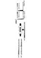
さらに、ZC系列では、巡回シフト系列(以下、巡回シフト系列番号をmとする)も利用することができる。ここで、巡回シフト系列(Cyclic shift sequence)とは、同一系列番号rにおいて巡回シフト量(以下、単に「シフト量」という)が異なるZC系列であり、時間軸上でシフト量分だけ巡回シフトさせることで生成可能である。例えば、系列長N=12、シフト量Δ=6におけるZC系列(m=0)とその巡回シフト系列(m=1)を図1に示す。図では、ZC系列(m=0)がa(0)〜a(11)の順で構成されるのに対して、その巡回シフト系列(m=1)はm=0のZC系列がΔ(=6)シンボル分巡回シフトされ、a(6)〜a(11)、a(0)〜a(5)の順で構成される。 Further, in the ZC sequence, a cyclic shift sequence (hereinafter, the cyclic shift sequence number is m) can be used. Here, the cyclic shift sequence is a ZC sequence having a different cyclic shift amount (hereinafter simply referred to as “shift amount”) in the same sequence number r, and is cyclically shifted by the shift amount on the time axis. Can be generated. For example, FIG. 1 shows a ZC sequence (m = 0) and its cyclic shift sequence (m = 1) with a sequence length N = 12, and a shift amount Δ = 6. In the figure, the ZC sequence (m = 0) is configured in the order of a (0) to a (11), whereas the cyclic shift sequence (m = 1) of the ZC sequence of m = 0 is Δ ( = 6) The symbols are cyclically shifted by symbols, and are configured in the order of a (6) to a (11) and a (0) to a (5).
次に、受信機におけるRSの処理について説明する。上記m=0とm=1の2つの系列が同一タイミング、同一周波数で多重されたとき、受信機の相関器における相関結果は、m=0の系列とm=1の系列がそれぞれシフト量Δだけずれたタイミングで高い相関値(以下、「相関値ピーク」という)が発生する(図2参照)。なお、シフト量Δは、遅延波の最大遅延時間より大きく設定するため、各巡回シフト系列の相関値ピークはシフト量Δの範囲内のみに生じる。そのため、所望の巡回シフト系列の相関値が存在する区間(ウィンドウ部分)の相関値のみを抽出することにより、図3に示すように、各巡回シフト系列の相関結果を分離して検出することが可能となる。したがって、巡回シフト系列は、各シフト量の相関値がそれぞれのウィンドウ内に存在する条件下において直交系列として利用できる。 Next, RS processing in the receiver will be described. When the two sequences of m = 0 and m = 1 are multiplexed at the same timing and the same frequency, the correlation result in the correlator of the receiver is that the sequence of m = 0 and the sequence of m = 1 are each shifted by the shift amount Δ A high correlation value (hereinafter referred to as “correlation value peak”) is generated at a timing shifted by a certain amount (see FIG. 2). Since the shift amount Δ is set larger than the maximum delay time of the delayed wave, the correlation value peak of each cyclic shift sequence occurs only within the range of the shift amount Δ. Therefore, by extracting only the correlation value of the section (window part) where the correlation value of the desired cyclic shift sequence exists, the correlation result of each cyclic shift sequence can be detected separately as shown in FIG. It becomes possible. Therefore, the cyclic shift sequence can be used as an orthogonal sequence under the condition that the correlation value of each shift amount exists in each window.
なお、各巡回シフト系列の相関演算は、周波数領域で処理されることが一般的であり、
図2に示した相関器は、DFT(Discrete Fourier Transform)処理、ZC系列(m=0)での除算、IFFT(Inverse Fast Fourier Transform)処理を行う。Note that the correlation calculation of each cyclic shift sequence is generally processed in the frequency domain,
The correlator shown in FIG. 2 performs DFT (Discrete Fourier Transform) processing, division by a ZC sequence (m = 0), and IFFT (Inverse Fast Fourier Transform) processing.
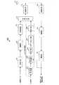
図4は、一般的な受信機の構成を示すブロック図である。この図において、DFT部11は、受信したRSにDFT処理を施し、DFT処理を施したRSをサブキャリアデマッピング部12に出力する。 FIG. 4 is a block diagram showing a configuration of a general receiver. In this figure, the DFT
サブキャリアデマッピング部12は、DFT部11から出力されたRSのうち、送信帯域に対応した部分を抽出し、抽出したRSを除算部13に出力する。 The subcarrier demapping
除算部13は、サブキャリアデマッピング部12から出力されたRSをZC系列(m=0)で除算し、除算結果である相関値をIDFT部14に出力する。 The
IDFT部14は、除算部13から出力された相関値にIDFT(Inverse Discrete Fourier Transform)処理を施し、IDFT処理を施した相関値をマスク処理部15に出力する。 The
マスク処理部15は、IDFT部14から出力された相関値のうち、所望の巡回シフト系列の相関値が存在する区間(ウィンドウ部分)の相関値のみが抽出され、抽出された相関値をチャネル推定値としてDFT部16に出力する。 The
DFT部16は、マスク処理部15から出力された相関値にDFT処理を施し、DFT処理を施した信号を出力する。 The DFT
なお、F(X)は、ZC系列(または、その巡回シフト系列)をDFT処理することにより生じるX番目のシンボルを表す。あるいは、直接ZC系列を周波数領域で生成することにより生じるX番目のシンボルを表す。 F (X) represents the Xth symbol generated by performing DFT processing on the ZC sequence (or its cyclic shift sequence). Alternatively, it represents the Xth symbol generated by directly generating a ZC sequence in the frequency domain.
一方、上り回線で用いられるRSの中で、データの復調に用いられるチャンネル推定用参照信号(以下、DM−RS:Demodulation Reference Signal)は、データ送信帯域幅と同じ帯域で送信されることが検討されている。つまり、データ送信帯域幅が狭帯域である場合には、DM−RSも狭帯域で送信されることになる。例えば、データ送信帯域幅が1RB(Resource block)であればDM−RSも1RBとなり、データ送信帯域幅が2RBであればDM−RSも2RBとなる。ここで、RBは、周波数軸上における無線周波数割当単位であり、例えば、1つあるいは複数の周波数キャリア(以下、サブキャリア: subcarrier)から構成される。 On the other hand, among RSs used in uplink, a channel estimation reference signal (hereinafter referred to as DM-RS) used for data demodulation is considered to be transmitted in the same band as the data transmission bandwidth. Has been. That is, when the data transmission bandwidth is a narrow band, the DM-RS is also transmitted in the narrow band. For example, if the data transmission bandwidth is 1 RB (Resource block), DM-RS is also 1 RB, and if the data transmission bandwidth is 2 RB, DM-RS is also 2 RB. Here, RB is a radio frequency allocation unit on the frequency axis, and is composed of, for example, one or a plurality of frequency carriers (hereinafter referred to as subcarriers).
なお、1RBが12サブキャリアで構成されるとすると、1RBを利用するDM−RSでは系列長Nが12シンボル(Nが素数でない場合)又は11シンボル、13シンボル(Nが素数である場合)のZC系列を、2RBを利用するDM−RSでは系列長Nが24シンボル(Nが素数でない場合)又は23シンボル、29シンボル(Nが素数である場合)のZC系列を使用する。ここで、系列長Nが11シンボル及び23シンボルのZC系列を用いる場合はそれぞれ巡回拡張(cyclic extension)を行って12シンボル分及び24シンボル分のDM−RSを生成する。また、系列長Nが13シンボル及び29シンボルのZC系列を用いる場合はそれぞれトランケーション(Truncation)を行って12シンボル分及び24シンボル分のDM−RSを生成する。 If 1 RB is composed of 12 subcarriers, the DM-RS using 1 RB has a sequence length N of 12 symbols (when N is not a prime number), 11 symbols, or 13 symbols (when N is a prime number). In DM-RS using 2RB, a ZC sequence having a sequence length N of 24 symbols (when N is not a prime number), 23 symbols, or 29 symbols (when N is a prime number) is used. Here, when a ZC sequence having a sequence length N of 11 symbols and 23 symbols is used, cyclic extensions are performed to generate DM-RSs for 12 symbols and 24 symbols, respectively. When ZC sequences having a sequence length N of 13 symbols and 29 symbols are used, truncation is performed to generate DM symbols for 12 symbols and 24 symbols.
また、DM−RSはRS間のセル間干渉を低減するために、セル間では異なるZC系列を割り当てることが検討されている。このとき、狭帯域伝送での利用可能な直交系列、あるいは相互相関の低い準直交(quasi-orthogonal)系列数の不足が課題として挙げられて
いる。DM−RSの送信時間が同じであるとすると、狭帯域伝送時ではDM−RSの系列長(シンボル数)が減少する。そのため、系列数(N−1)も減少し、同一ZC系列を利用するセル間距離が小さくなる。その結果、DM−RSのセル間干渉の影響が大きくなり、チャネル推定精度を著しく劣化させることになる。In addition, in order to reduce inter-cell interference between RSs in DM-RS, it is considered to assign different ZC sequences between cells. At this time, the shortage of the number of orthogonal sequences that can be used in narrowband transmission or the number of quasi-orthogonal sequences with low cross-correlation has been raised. Assuming that the DM-RS transmission times are the same, the DM-RS sequence length (number of symbols) decreases during narrowband transmission. Therefore, the number of sequences (N-1) is also reduced, and the inter-cell distance using the same ZC sequence is reduced. As a result, the influence of inter-cell interference of DM-RS is increased, and the channel estimation accuracy is significantly degraded.
非特許文献1及び2において、狭帯域伝送における同一ZC系列を利用するセル間距離を長くする目的で、基地局間の時間同期あるいは送信フレームタイミング同期が確立しているセル間(例えば、同一基地局に属するセル)では、同一系列番号rの異なる巡回シフト系列mを割り当てることが提案されている(図5参照)。例えば、同一基地局に属するセル(図5に斜線で示した3つのセル)では、同一系列番号rのZC系列を利用する。セル#1では巡回シフト系列m=1,4を、セル#2では巡回シフト系列m=2,5を、セル#3では巡回シフト系列m=3,6を利用する。その結果、系列番号rが同じZC系列を利用するセル間の距離を長くすることができる。また、同一基地局間のDM−RS間は準直交(異なる系列番号rのZC系列間)ではなく直交(巡回シフト系列のZC系列間)となるため、DM−RSの近隣セルからの干渉を低減し、チャネル推定精度を向上させることができる。
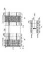
ところで、DM−RSはデータ送信帯域と同一帯域で送信され、ユーザ間のデータ及びRSは周波数多重(Localized FDM)される。また、データ送信帯域は各セルのスケジューラによって決定される。そのため、各セルでDM−RSの送信帯域が異なる(図6参照)。なお、図6では、セル#1ではRB1とRB2(図6(a))を、セル#2ではRB2とRB3(図6(b))を利用してDM−RS(帯域幅360kHz)を送信している。この場合、セル#1及びセル#2の基地局ではそれぞれ送信帯域が異なるDM−RSを合成して受信することになる(図6(c))。ここで、セル#1において合成されたDM−RSの遅延プロファイル(相関値)をセル#1のRS送信帯域で計算すると、セル#2のDM−RSの相関値ピークがあらかじめ時間領域で設定されたシフト量とは異なる位置に生じる(図7参照)。 By the way, DM-RS is transmitted in the same band as the data transmission band, and the data and RS between users are frequency-multiplexed (Localized FDM). The data transmission band is determined by the scheduler of each cell. Therefore, the transmission band of DM-RS differs in each cell (refer FIG. 6). In FIG. 6, DM-RS (bandwidth 360 kHz) is transmitted using RB1 and RB2 (FIG. 6A) in
これは、セル#2の移動局から到来したDM−RSに対する除算処理(除算部13)がZC系列(m=0)による除算処理とは異なるためである。例えば、図7に示すように、セル#2のDM−RSがセル#1で受信された場合、このDM−RSの先頭のスペクトラム値はZC系列(m=0)の7番目のスペクトラム値で除算される。その結果、セル#2のDM−RSの相関値ピークがあらかじめ時間領域で設定されたシフト量とは異なる位置に生じる。このとき、セル#2のDM−RSの遅延プロファイル(相関値)がセル#1のウィンドウ内に生じた場合、セル#1とセル#2の遅延プロファイルを分離することができず、セル#2のDM−RSがセル#1にとって干渉成分となるため、セル#1のDM−RSを用いたチャネル推定精度を劣化させる。なお、以下において、セル#1とセル#2及び巡回シフト系列m=1とm=2を用いて説明するが、これに限定されるものではない。 This is because the division processing (dividing unit 13) for the DM-RS arriving from the mobile station in
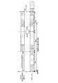
図8に、受信帯域幅が24サブキャリア(360kHz)であり、周波数領域で12サブキャリア分(180kHz)異なる帯域で相関を計算する場合の相関結果を示す。ここ
では、系列長N=24、系列番号r=13であるZC系列を利用し、シフト量Δ=12と設定した。また、図8では、セル#1において、巡回シフト系列の送信帯域と相関値を計算する帯域とが異なる場合の相関結果を点線で示し、これらが一致している場合の相関結果を実線で示した。図8より、実線ではシフト量12の相関値ピークが正確に後半部分に生じるのに対して、点線では相関値ピークが後半部分ではなく、前半部分に生じることが分かる。FIG. 8 shows the correlation results when the reception bandwidth is 24 subcarriers (360 kHz) and the correlation is calculated in a band different by 12 subcarriers (180 kHz) in the frequency domain. Here, a ZC sequence having a sequence length N = 24 and a sequence number r = 13 is used, and the shift amount Δ = 12. In FIG. 8, in
このように、従来、自セルのみを考慮して巡回シフト系列を割り当て、生成している。より具体的には、ZC系列及び巡回シフトZC系列は、送信帯域幅(RB数)のみに基づいて割り当てられている。したがって、相関演算で利用する自セルのZC系列の要素と、隣接セルのZC系列の要素とが、異なる帯域に割り当られる場合にはこれらのZC系列を異なる帯域に割り当てられる場合と同じ関係に保つことができないという課題がある。なお、この課題はDM−RSに限定されるものではないため、以降ではDM−RSに限定せずにCQI推定用参照信号であるSRS(Sounding Reference Signal)、下り回線のRS、同期用パイロット信号なども含めてRSとする。 Thus, conventionally, cyclic shift sequences are allocated and generated in consideration of only the own cell. More specifically, the ZC sequence and the cyclic shift ZC sequence are allocated based only on the transmission bandwidth (number of RBs). Therefore, when the elements of the ZC sequence of the own cell and the elements of the ZC sequence of the neighboring cell used in the correlation calculation are assigned to different bands, the relationship is the same as when these ZC sequences are assigned to different bands. There is a problem that it cannot be maintained. Since this problem is not limited to DM-RS, SRS (Sounding Reference Signal), which is a reference signal for CQI estimation, downlink RS, and pilot signal for synchronization is not limited to DM-RS. And so on.
本発明の目的は、自セルと隣接セルとにおけるRS送信帯域が異なる場合でも、CAZAC系列からなる参照信号を用いたチャネル推定精度の劣化を回避する無線送信装置、無線送信方法、無線受信装置及び無線受信方法を提供することである。An object of the present invention is to provide a wireless transmission device, a wireless transmission method, a wireless reception device, and a wireless transmission device that avoid deterioration of channel estimation accuracy using a reference signal composed of a CAZAC sequence even when the RS transmission band is different between the own cell and the neighboring cell It is to provide awireless reception method .
本発明の無線送信装置は、複数のセル間で共通の基準点からの送信帯域位置及び送信帯域幅と、系列のスタート番号とが対応付けられた複数のセル間で共通の対応関係に基づいて、前記系列の配列を決定する決定手段と、決定された前記系列の配列に基づいて、送信信号を送信する送信手段と、を具備する構成を採る。The wireless transmission device of the present invention is based on acorrespondence relationship common to a plurality of cells in whicha transmission band position and a transmission bandwidth from a common reference pointamong a plurality of cells are associated with a start number of a sequence. , take a determining means for determining the sequence ofsaid sequence,based on the sequenceof the determinedthesequence, a configuration and a transmitting means for transmittingatransmission signal.
本発明によれば、自セルと隣接セルとにおけるRS送信帯域が異なる場合でも、CAZAC系列からなる参照信号を用いたチャネル推定精度の劣化を回避することができる。 According to the present invention, it is possible to avoid deterioration in channel estimation accuracy using a reference signal made up of a CAZAC sequence even when the RS transmission band is different between the own cell and the adjacent cell.
以下、本発明の実施の形態について、図面を参照して詳細に説明する。ただし、実施の形態において、同一機能を有する構成には同一符号を付し、重複する説明は省略する。また、以下では、高い相関値の発生する領域(1つまたは複数の高い相関値)を「相関値ピーク」と定義して説明する。 Hereinafter, embodiments of the present invention will be described in detail with reference to the drawings. However, in the embodiment, configurations having the same functions are denoted by the same reference numerals, and redundant description is omitted. In the following description, a region where one or more high correlation values are generated (one or more high correlation values) is defined as a “correlation value peak”.
(実施の形態1)
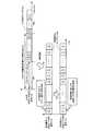
本発明の実施の形態1に係る移動局100の構成について、図9を用いて説明する。受信RF102部は、アンテナ101を介して受信した信号にダウンコンバート、A/D変換等の受信処理を施し、受信処理を施した信号を復調部103に出力する。復調部103は、受信処理が施された信号に等化処理、復調処理を施し、これらの処理を施した信号を復号部104に出力する。復号部104は、復調処理が施された信号に復号処理を施し、データ信号及び制御情報を抽出する。また、抽出された制御情報のうち、RB(Resource
Block)割当情報がRS生成部108の配列生成部109に出力される。(Embodiment 1)
The configuration of
Block) allocation information is output to the
符号化部105は、送信データを符号化し、符号化データを変調部106に出力する。変調部106は、符号化データを変調し、変調信号をRB割当部107に出力する。RB割当部107は、変調信号をRBに割り当て、RBに割り当てた変調信号を多重化部113に出力する。
RS生成部108は、配列生成部109、マッピング部110、IFFT部111、巡回シフト部112を備えており、RSテーブルと復号部104から出力されたRB割当情報とに基づいて、ZC系列からRS(Reference Signal)を生成し、生成したRSを多重化部113に出力する。以下、RS生成部113内の各部の構成について説明する。 The
配列生成部109は、RSテーブルを備え、復号部104から出力されたRB割当情報に対応する帯域のZC系列をRSテーブルから抽出し、抽出したZC系列をマッピング部110に出力する。ここで、RSテーブルとは、システム帯域内で便宜的に定めた周波数を基準点としたとき、この基準点から周波数の高い方(又は、低い方)に順番にZC系列のスペクトラム番号を割り振り、系列長以内の番号で繰り返しスペクトラムを配列したものである。なお、RSテーブルの具体例は後述する。
マッピング部110は、配列生成部109から出力されたZC系列を移動局100の送信帯域に対応した帯域にマッピングし、マッピングしたZC系列をIFFT部111に出力する。IFFT部111は、マッピング部110から出力されたZC系列にIFFT(Inverse Fast Fourier Transform)処理を施し、IFFT処理を施したZC系列を巡回シフト部112に出力する。
巡回シフト部112は、IFFT部111から出力されたZC系列を所定のシフト量分巡回シフトし、巡回シフトしたZC系列をRSとして多重化部113に出力する。ここで
、巡回シフト部112で行う巡回シフトのシフト量はセル毎あるいは移動局毎に個別に割り当てられた値であり、移動局は基地局から通知される情報に基づいてシフト量を決定する。この時通知される情報の通知形態としては、シフト量そのものが通知されてもよいし、その他のどのような通知形態でもよい。同一基地局に属する複数のセルに巡回シフト系列が割り当てられる場合には、各セルに割り当てられるシフト量は、各々のセルに属する移動局が同一送信帯域で前記シフト量に基づいて巡回シフト系列を送信した場合に、基地局で相関結果を分離できる程度の値に設定される。なお、巡回シフトはIFFT部の前で行ってもよい。この場合は周波数領域で処理するため、巡回シフトはサブキャリア毎の位相回転により実現される。
多重化部113は、RB割当部107から出力された送信データ(変調信号)と巡回シフト部112から出力されたZC系列(参照信号)とを時間多重し、多重信号を送信RF部114に出力する。なお、多重化部113における多重化方法は、時間多重に限らず、周波数多重、符号多重、複素空間上のIQ多重であってもよい。 Multiplexing
送信RF部114は、多重化部113から出力された多重信号にD/A変換、アップコンバート、増幅等の送信処理を施し、送信処理を施した信号をアンテナ101から無線送信する。 The
本発明の実施の形態1に係る基地局150の構成について、図10を用いて説明する。符号化部151は、送信データ及び制御信号を符号化し、符号化データを変調部152に出力する。変調部152は、符号化データを変調し、変調信号を送信RF部153に出力する。送信RF部153は、変調信号にD/A変換、アップコンバート、増幅等の送信処理を施し、送信処理を施した信号をアンテナ154から無線送信する。 The configuration of
受信RF部155は、アンテナ154を介して受信した信号にダウンコンバート、A/D変換等の受信処理を施し、受信処理を施した信号を分離部156に出力する。 The
分離部156は、受信RF部155から出力された信号をRSと、データ信号及び制御信号とに分離し、分離したRSをDFT部157に、データ信号及び制御信号をDFT部164にそれぞれ出力する。 The
DFT部157は、分離部156から出力されたRSにDFT処理を施し、時間領域から周波数領域の信号に変換し、周波数領域に変換したRSを伝搬路推定部158のデマッピング部159に出力する。 The
伝搬路推定部158は、デマッピング部159、除算部160、IFFT部161、マスク処理部162、DFT部163を備え、DFT部157から出力されたRSに基づいて、伝搬路を推定する。 The propagation path estimation unit 158 includes a
デマッピング部159は、DFT部157から出力された信号から各移動局の送信帯域に対応した部分が抽出され、抽出された各信号を除算部160に出力する。
除算部160は、図9に示した移動局100の配列生成部109が備えるRSテーブルと同一のRSテーブルを備え、デマッピング部159から出力された信号をRSテーブルに対応するZC系列で除算し、除算結果をIFFT部161に出力する。IFFT部161は、除算部160から出力された信号にIFFT処理を施し、IFFT処理を施した信号をマスク処理部162に出力する。 The
マスク処理部162は、IFFT部161から出力された信号にマスク処理を施すこと
により、所望の巡回シフト系列の相関値が存在する区間(ウィンドウ部分)の相関値を抽出し、抽出した相関値をDFT部163に出力する。The mask processing unit 162 performs a mask process on the signal output from the
DFT部163は、マスク処理部162から出力された相関値にDFT処理を施し、DFT処理を施した相関値を周波数領域等化部166に出力する。なお、DFT部163から出力された信号は、伝搬路の周波数応答を表すものである。 The
DFT部164は、分離部156から出力されたデータ信号及び制御信号にDFT処理を施し、時間領域から周波数領域の信号に変換し、周波数領域に変換したデータ信号及び制御信号をデマッピング部165に出力する。 The
デマッピング部165は、DFT部164から出力された信号から各移動局の送信帯域に対応した部分のデータ信号及び制御信号が抽出され、抽出された各信号を周波数領域等化部166に出力する。 The
周波数領域等化部166は、伝搬路推定部158内のDFT部163から出力された信号(伝搬路の周波数応答)を用いて、デマッピング部165から出力されたデータ信号及び制御信号に等化処理を施し、等化処理を施した信号をIFFT部167に出力する。 The frequency
IFFT部167は、周波数領域等化部166から出力されたデータ信号及び制御信号にIFFT処理を施し、IFFT処理を施した信号を復調部168に出力する。復調部168は、IFFT処理が施された信号に復調処理を施し、復調処理を施した信号を復号部169に出力する。復号部169は、復調処理が施された信号に復号処理を施し、受信データを抽出する。
なお、除算部160では、RSテーブルに対応するZC系列で除算し、マスク処理部162でマスク処理を施すことにより、所望の巡回シフト系列の相関値が存在する区間(ウィンドウ部分)の相関値を抽出するとしたが、これと等価な受信処理であれば別の方法でもよい。例えば、除算部160でRSテーブルに対応しない一般的なZC系列で除算し、マスク処理部162でRSテーブルに対応したマスク処理を施すことにより、所望の巡回シフト系列の相関値が存在する区間(ウィンドウ部分)の相関値を抽出してもよい。 The
次に、上述した配列生成部109の動作について図11を用いて説明する。ここでは、セル#2において、系列長N=24、系列番号r=1の巡回シフト系列m=2であるZC系列を利用し、シフト量Δ=12とする。また、配列生成部109が備えるRSテーブルは、図11に示すように、基準点からF(1)〜F(24)のスペクトラム番号を割り振り、繰り返し配列したものとなっている。ここで、F(x)は、ZC系列を周波数変換することにより得られるx番目のZC系列の周波数スペクトルを表す。あるいは、ZC系列を周波数領域で生成した場合のx番目のシンボルを表す。 Next, the operation of the above-described
配列生成部109は、例えば、図11に示すように、RB割当情報として基準点から12サブキャリア分(180kHz)離れた帯域から送信帯域幅分(例えば、RB2及びRB3)が指示された場合、このRB割当情報に対応するZC系列をRSテーブルから抽出すると、F(13)〜F(24),F(1)〜F(12)の配列を抽出する。このとき、配列の先頭、すなわち、基準点に最も近いスペクトル番号(以下、「スタート番号」という)は13となる。ちなみに、基準点から0kHz離れた帯域(例えば、RB1及びRB2)におけるスペクトラムはスタート番号が1である。 For example, as illustrated in FIG. 11, the
なお、他セル(例えば、セル#1)においても、基準点から180kHz離れた位置におけるスペクトラムのスタート番号は13であり、基準点から0kHz離れた位置におけ
るスペクトラムのスタート番号は1である。また、参考までに、図11には、従来方法により生成される配列は送信するサブキャリア位置(RBの位置)にかかわらず、常にスタート番号が1から始まることを示している。In other cells (for example, cell # 1), the spectrum start number is 13 at a position 180 kHz away from the reference point, and the spectrum start number is 1 at a
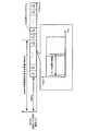
このように、相関演算を行う帯域に対して、自セルのZC系列の要素と、隣接セルのZC系列の要素とを、送信される帯域にかかわらず同じ関係を保つようにする(つまり、相対関係を維持する)ことで、図12に示すように、時間領域で設定したシフト量に応じた位置に相関値ピークを発生させることができる。同じ関係を保つ方法としては、RS送信帯域とZC系列のスペクトラムのスタート番号とを対応付ける、すなわち、各送信帯域の基準点から異なる周波数帯域幅とZC系列のスペクトラムのスタート番号とを系列長に応じた特定の関係を満たすように対応付けることなどが挙げられる。そして、この方法によって、巡回シフト系列の送信帯域と相関を計算する帯域が異なる場合でも、従来では設定したウィンドウと異なるウィンドウ内に現れていた相関値ピークが、設定したウィンドウ内に現れるようになる。よって、シフト量に対応したウィンドウ以外への干渉を軽減することができ、チャネル推定精度を改善することができる。また、系列番号にかかわらず、同一処理で相関値ピークの位置を一定にできる。 In this way, the ZC sequence element of the own cell and the ZC sequence element of the neighboring cell are kept in the same relationship regardless of the transmitted band with respect to the band for which the correlation calculation is performed (that is, relative By maintaining the relationship, a correlation value peak can be generated at a position corresponding to the shift amount set in the time domain, as shown in FIG. As a method of maintaining the same relationship, the RS transmission band is associated with the start number of the spectrum of the ZC sequence, that is, the frequency bandwidth different from the reference point of each transmission band and the start number of the spectrum of the ZC sequence according to the sequence length. And matching so as to satisfy the specific relationship. By this method, even when the transmission band of the cyclic shift sequence and the band for calculating the correlation are different, the correlation value peak that has appeared in a window different from the window that has been set conventionally appears in the set window. . Therefore, interference other than the window corresponding to the shift amount can be reduced, and the channel estimation accuracy can be improved. Further, the position of the correlation value peak can be made constant by the same process regardless of the sequence number.
ここで、帯域幅24サブキャリア(360kHz)で相関を計算する場合において、周波数領域で12サブキャリア(180kHz)異なる帯域で送信される巡回シフト系列に対する相関結果を図13に示す。なお、系列長N=24、系列番号r=13であるZC系列を利用し、シフト量Δ=12と設定した。また、巡回シフト系列の送信帯域と相関値を計算する帯域が異なる場合を点線、これらが一致している場合を実線で示した。この図より、実線でも点線でもシフト量Δ=12の相関値ピークが正確に後半部分に生じることがわかる。 Here, in the case of calculating the correlation with a bandwidth of 24 subcarriers (360 kHz), FIG. 13 shows the correlation results for cyclic shift sequences transmitted in different bands of 12 subcarriers (180 kHz) in the frequency domain. A ZC sequence having a sequence length N = 24 and a sequence number r = 13 was used, and a shift amount Δ = 12. In addition, a dotted line indicates a case where a transmission band of a cyclic shift sequence and a band for calculating a correlation value are different, and a solid line indicates a case where these coincide with each other. From this figure, it can be seen that a correlation value peak with a shift amount of Δ = 12 is accurately generated in the latter half portion of both the solid line and the dotted line.
このように実施の形態1によれば、RS送信帯域とZC系列のスペクトラムのスタート番号とを対応付けることにより、時間領域で設定したシフト量に応じた位置に相関値ピークを発生させることができ、シフト量に対応したウィンドウ以外への干渉を軽減することができ、チャネル推定精度を改善することができる。 Thus, according to the first embodiment, by associating the RS transmission band and the start number of the spectrum of the ZC sequence, a correlation value peak can be generated at a position corresponding to the shift amount set in the time domain, Interference outside the window corresponding to the shift amount can be reduced, and the channel estimation accuracy can be improved.
なお、本実施の形態では、図11に示すRSテーブルを例に説明したが、本発明はこれに限らず、特定の関係を満たし、送受信側双方で共有しているRSテーブルであればよい。また、上記のRSテーブルを必ずしも備える必要はなく、これと等価な処理が行えればRSテーブルを備えていなくてもよい。 In the present embodiment, the RS table shown in FIG. 11 has been described as an example. However, the present invention is not limited to this, and any RS table that satisfies a specific relationship and is shared by both transmitting and receiving sides may be used. The RS table is not necessarily provided, and the RS table may not be provided as long as an equivalent process can be performed.
また、本実施の形態では、移動局100におけるRS生成部108を図9に示すものとして説明したが、図14A及び図14Bに示すような構成でもよい。図14Aは周波数軸領域でZC系列を生成する場合の構成であり、図14Bは時間軸領域でZC系列を生成する場合の構成である。なお、図14Aに示す構成では、位相回転部において時間領域の巡回シフトに対応するように、周波数領域の各サブキャリアに対して位相回転が加えられる。 Further, in the present embodiment, the
なお、本実施の形態では、1RBを12サブキャリア(180kHz)として説明したが、RBあたりのサブキャリア数、サブキャリア間隔、帯域幅はこれに限定しない。 Note that although 1 RB is described as 12 subcarriers (180 kHz) in this embodiment, the number of subcarriers per RB, the subcarrier interval, and the bandwidth are not limited thereto.
また、本実施の形態では、参照信号としてDM−RSを例に説明したが、これに限定されるものではなく、CAZAC系列を用いるその他の参照信号でもよい。 In the present embodiment, the DM-RS has been described as an example of the reference signal. However, the present invention is not limited to this, and another reference signal using a CAZAC sequence may be used.
なお、配列生成部109で算出する送信帯域に応じたZC系列のスタート番号は、基地局側で算出し、スタート番号を通知する構成であってもよい。 Note that the start number of the ZC sequence corresponding to the transmission band calculated by the
(実施の形態2)
実施の形態1では、ZC系列長が1RBのサブキャリア数の倍数である場合について説明したが、本発明の実施の形態2では、ZC系列長が素数である場合について説明する。(Embodiment 2)
In the first embodiment, the case where the ZC sequence length is a multiple of the number of subcarriers of 1 RB has been described, but in the second embodiment of the present invention, the case where the ZC sequence length is a prime number will be described.
ただし、実施の形態2に係る移動局及び基地局の構成は、実施の形態1の図9及び図10に示した構成と同様であるので、図9及び図10を援用する。 However, since the configurations of the mobile station and the base station according to
一般に、系列長が素数であるZC系列をRS送信帯域のサブキャリア数に合わせるため、巡回拡張(Cyclic extension)によるRS生成及びトランケーション(Truncation)によるRS生成が検討されている。以下、それぞれのRSについて説明する。 In general, in order to match a ZC sequence whose sequence length is a prime number with the number of subcarriers in the RS transmission band, RS generation by cyclic extension and RS generation by truncation have been studied. Hereinafter, each RS will be described.
ZC系列の巡回拡張によるRSは、一般に、RS送信帯域におけるサブキャリア数よりも小さく、かつ、最も近い素数を系列長とするZC系列を利用し、このZC系列の一部をサブキャリア数に合わせて繰り返す。例えば、RS送信帯域が24サブキャリアである場合、23系列長のZC系列が選択される。そして、このZC系列をサブキャリア数に合わせるために、選択されたZC系列の最初の1シンボルが末尾に付加される。 RS by cyclic extension of a ZC sequence is generally smaller than the number of subcarriers in the RS transmission band and uses a ZC sequence having the nearest prime number as a sequence length, and a part of this ZC sequence is matched to the number of subcarriers. And repeat. For example, when the RS transmission band is 24 subcarriers, a 23-sequence length ZC sequence is selected. Then, in order to match this ZC sequence to the number of subcarriers, the first symbol of the selected ZC sequence is added to the end.
次に、巡回拡張によるRS構成を用いるときの配列生成部109の動作について図15を用いて説明する。ここでは、セル#2において、系列長N=23、系列番号r=1の巡回シフト系列m=2であるZC系列を利用し、シフト量Δ=12とする。また、配列生成部109が備えるRSテーブルは、図15に示すように、基準点からF(1)〜F(23)のスペクトラム番号を割り振り、繰り返し配列したものとなっている。 Next, the operation of the
配列生成部109は、例えば、図15に示すように、RB割当情報として基準点から12サブキャリア(180kHz)離れた帯域から送信帯域幅分(例えば、RB2及びRB3)が指示された場合、このRB割当情報に対応するZC系列をRSテーブルから抽出すると、F(13)〜F(23),F(1)〜F(13)の配列を抽出する。また、基準点から24サブキャリア(360kHz)離れた帯域から送信帯域幅分(例えば、RB3及びRB4)が指示された場合、このRB割当情報に対応するZC系列をRSテーブルから抽出すると、F(2)〜F(23),F(1)及びF(2)の配列を抽出する。 For example, as illustrated in FIG. 15, the
次に、ZC系列のトランケーションによるRS生成は、一般にRS送信帯域におけるサブキャリア数よりも大きく、かつ、最も近い素数を系列長とするZC系列を利用し、このZC系列の一部をサブキャリア数に合わせてトランケートする(切り詰める)。例えば、RS送信帯域が24サブキャリアである場合、29系列長のZC系列が選択される。そして、このZC系列がサブキャリア数に合わせて5シンボルだけ切り詰められる。 Next, RS generation by truncation of a ZC sequence generally uses a ZC sequence that is larger than the number of subcarriers in the RS transmission band and has the nearest prime number as the sequence length, and a part of this ZC sequence is converted into the number of subcarriers. Truncate (truncate) to match. For example, when the RS transmission band is 24 subcarriers, a 29 sequence length ZC sequence is selected. This ZC sequence is truncated by 5 symbols in accordance with the number of subcarriers.
次に、トランケーションにより生成されるRSを用いるときの配列生成部109の動作について図16を用いて説明する。ここでは、セル#2において、系列長N=29、系列番号r=1の巡回シフト系列m=2であるZC系列を利用し、シフト量Δ=12とする。また、配列生成部109が備えるRSテーブルは、図16に示すように、基準点からF(1)〜F(29)のスペクトラム番号を割り振り、繰り返し配列したものとなっている。 Next, the operation of the
配列生成部109は、例えば、図16に示すように、RB割当情報として基準点から12サブキャリア(180kHz)離れた帯域から送信帯域幅分(例えば、RB2及びRB3)が指示された場合、このRB割当情報に対応するZC系列をRSテーブルから抽出すると、F(13)〜F(29),F(1)〜F(7)の配列を抽出することになる。また、基準点から24サブキャリア(360kHz)離れた帯域から送信帯域幅分(例えば、RB3及びRB4)が指示された場合、このRB割当情報に対応するZC系列をRSテー
ブルから抽出すると、F(25)〜F(29),F(1)〜F(19)の配列を抽出することになる。For example, as illustrated in FIG. 16, the
なお、ZC系列の巡回拡張及びトランケーションは、周波数領域ではなく、時間領域で行ってもよい。この場合、生成されるZC系列のスペクトラム数はサブキャリア数と同じであるため、実施の形態1と同じ方法で、サブキャリアに対して、スペクトラム成分を一意に割り当てる。 Note that the cyclic extension and truncation of the ZC sequence may be performed in the time domain instead of the frequency domain. In this case, since the number of spectrums of the generated ZC sequence is the same as the number of subcarriers, spectrum components are uniquely assigned to the subcarriers by the same method as in the first embodiment.
このように実施の形態2によれば、ZC系列長が素数であり、ZC系列長とサブキャリア数が異なる場合でも、実施の形態1と同様、時間領域で設定したシフト量に応じた位置に相関値ピークを発生させることができ、シフト量に対応したウィンドウ以外への干渉を軽減することができ、チャネル推定精度を改善することができる。 As described above, according to the second embodiment, even when the ZC sequence length is a prime number and the ZC sequence length is different from the number of subcarriers, the position according to the shift amount set in the time domain is the same as in the first embodiment. A correlation value peak can be generated, interference other than the window corresponding to the shift amount can be reduced, and the channel estimation accuracy can be improved.
なお、巡回拡張、トランケーションを用いずに、素数のままRSを構成する場合は、配列生成部109は巡回拡張を行う場合と同一の構成をとる。RSのサブキャリア数が24の場合、系列長N=23のZC系列の巡回拡張と同様にRSの配列生成を行い、そのうち1シンボルをNull(信号なし、あるいはゼロ)に置き換え、マッピング部110に出力する。ここで、Nullにするシンボルは、送信RBに該当するサブキャリアのうちいずれのサブキャリアでもよいが、周波数の最も低いあるいは最も高いサブキャリアにすることがZC系列の直交性を維持できるため好ましい。 In addition, when RS is comprised with a prime number without using cyclic extension and truncation, the arrangement | sequence production |
(実施の形態3)
本発明の実施の形態3に係る移動局200の構成について、図17を用いて説明する。図17が図9と異なる点は、RS生成部108をRS生成部201に変更した点である。(Embodiment 3)
The configuration of
RS生成部201は、第1巡回シフト部202、第2巡回シフト部203、DFT部204、マッピング部205、IFFT部206を備えており、ZC系列からRSを生成し、生成したRSを多重化部113に出力する。以下、RS生成部201内の各部の構成について説明する。 The RS generation unit 201 includes a first
第1巡回シフト部202は、ZC系列を所定のシフト量(送信帯域にかかわらず、セル毎あるいは移動局毎に割り当てられるシフト量)分巡回シフトし、巡回シフトしたZC系列を第2巡回シフト部203に出力する。 The first
第2巡回シフト部203は、第1巡回シフト部202から出力されたZC系列を送信帯域に応じたシフト量でさらに巡回シフトし、巡回シフトされたZC系列をDFT部204に出力する。このとき、送信帯域に応じたシフト量とは、系列長、系列番号、サブキャリア間隔及び、基準点(基準サブキャリア)と送信を行う周波数帯域との相対値に対応し、これらと特定の関係を満たすように対応付けられる。 Second
なお、この送信帯域に応じたシフト量は、基地局より通知あるいは予め定められることで送受信側双方が共有しているものとする。 It is assumed that the shift amount corresponding to the transmission band is shared by both the transmission and reception sides by being notified from the base station or determined in advance.
DFT部204は、第2巡回シフト部203から出力されたZC系列にDFT処理を施し、DFT処理を施したZC系列をマッピング部205に出力する。マッピング部205は、DFT部204から出力されたZC系列を移動局の送信帯域に対応した帯域にマッピングし、マッピングしたZC系列をIFFT部206に出力する。IFFT部206は、マッピング部205から出力されたZC系列にIFFT処理を施し、IFFT処理を施したZC系列をRSとして多重化部113に出力する。 The
本発明の実施の形態3に係る基地局の構成は、実施の形態1の図10に示した構成と同様であり、除算部160の機能が異なるのみなので、除算部160について図10を援用して説明する。 The configuration of the base station according to
除算部160は、デマッピング部159から出力された信号をDFT処理されたZC系列で除算し、除算結果をIFFT部に出力する。なお、DFT処理されたZC系列は、時間領域でZC系列(m=0)に第2巡回シフト部203で送信帯域に応じて加えたシフト量を加え、DFT処理を行ったものである。また、ZC系列は基準点から0kHZ離れた帯域(例えば、RB1とRB2)でも、基準点から12サブキャリア(180kHz)離れた帯域(例えば、RB2とRB3)でもZC系列のスペクトラムのスタート番号を1とする。
なお、除算部160では、ZC系列(m=0)に時間領域で送信帯域に応じたシフト量を加えたZC系列(m=0)で除算処理するとしたが、これに等価な方法であれば別の方法でもよい。例えば、ZC系列(m=0)に時間領域でZC系列(m=0)に所定のシフト量(送信帯域にかかわらず、セル毎あるいは移動局毎に割り当てられるシフト量)および送信帯域に応じたシフト量を加えたZC系列(m=0)で除算処理し、マスク処理部162で所望のウィンドウにマスク処理を施すことにより、所望の巡回シフト系列の相関値が存在する区間(ウィンドウ部分)の相関値を抽出してもよい。 The
次に、上述した第2巡回シフト部203の動作について図18を用いて説明する。ここでは、セル#2において、系列長N=24、系列番号r=2の巡回シフト系列m=2であるZC系列を利用する。 Next, the operation of the above-described second
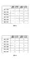
第2巡回シフト部203は、時間領域で設定した第1巡回シフト部202のシフト量に加えて、図18に示すように、巡回シフト系列の送信帯域に応じて時間領域でシフト量を変更する。なお、このシフト量は任意の帯域で相関値を計算しても第1巡回シフト部202で設定した巡回シフト量として検出されるように送信RS信号に追加的にシフト量を与えるものであり、このシフト量は系列長、系列番号、サブキャリア間隔及び、基準点(基準サブキャリア)と送信を行う周波数帯域との相対値によっても異なる。例えば、サブキャリア間隔が15kHzにおける特定の関係を満たすシフト量(補正シフト量)の一例を表に示す。ここでは、系列長23のZC系列が基準点から12サブキャリア(1RB)異なる帯域に割当てられた場合の巡回シフト量のずれ、および巡回シフト量から求めた補正シフト量を示す。
この巡回シフト量を式で表すと以下になる。1サブキャリア間隔(15kHz)の周波数オフセットを加えると、式(2)のcshiftで示すシンボル数分、ZC系列を巡回シフトさせることに相当する。
cShift = (N*s-1)/r・・・(2)This cyclic shift amount is expressed by the following equation. Adding a frequency offset of one subcarrier interval (15 kHz) corresponds to cyclically shifting the ZC sequence by the number of symbols indicated by cshift in Equation (2).
cShift = (N * s-1) / r (2)
ここで、N:系列長、r:系列番号(rはNと互いに素)、sはcShiftが整数となるため
の最小の自然数である。よって、Xサブキャリア分の異なる周波数帯域に割り当てられると、ZC系列ar(k)を式(3)のように巡回シフトさせた系列になる。
ar(k+X・cShift mod N)・・・(3)Here, N: sequence length, r: sequence number (r is relatively prime with N), and s is the minimum natural number for cShift to be an integer. Therefore, when assigned to different frequency bands corresponding to X subcarriers, the ZC sequence ar (k) is a sequence that is cyclically shifted as shown in Equation (3).
ar (k + X · cShift mod N) (3)
よって、Xサブキャリア分の異なる周波数帯域に割り当てる場合、ZC系列に式(4)の巡回シフトを加えることで式(3)の巡回シフト量を打ち消せるため、所望のタイミングに相関値ピーク位置を現すことができる。
−X・cShiftmod N・・・(4)Therefore, when allocating to different frequency bands for X subcarriers, the cyclic shift amount of equation (3) can be canceled by adding the cyclic shift of equation (4) to the ZC sequence, so that the correlation value peak position is set at a desired timing. Can appear.
-X · cShift mod N (4)
例えば、系列番号r=1、第1巡回シフト量Δ=12(スタート番号が13となる)の系列が入力されたと想定する。このとき、上記式に従って第2巡回シフト部203のシフト量を計算すると、基準点から0サブキャリア(0kHz)離れた帯域(例えば、RB1とRB2)では巡回シフト量0、基準点から12サブキャリア(180kHz)離れた帯域(例えば、RB2とRB3)ではシフト量11となる。つまり、基準点から0kHz離れた帯域の送信では巡回シフトを行わず(シフト量0)、スタート番号が13(T(13)と表示)の巡回シフト系列を出力する。一方、基準点から12サブキャリア(180kHz)離れた帯域での送信では、巡回シフト量12を施して巡回シフト系列のスタート番号を3(T(3))とする。 For example, it is assumed that a sequence having a sequence number r = 1 and a first cyclic shift amount Δ = 12 (start number is 13) is input. At this time, when the shift amount of the second
このとき、送信帯域に応じた上記テーブルを双方が記憶していてもよい。また、RB割当情報を上記式(2)〜(4)に当てはめて移動局、基地局がそれぞれ計算して求めてもよい。 At this time, both the tables according to the transmission band may be stored. Alternatively, the RB allocation information may be calculated by the mobile station and the base station by applying the above formulas (2) to (4).
なお、従来の方法では、送信する帯域、例えば、基準点から0サブキャリア(0kHz)及び12サブキャリア(180kHz)離れた帯域のいずれにもかかわらず、第1巡回シフト部202での巡回シフト系列番号に応じたスタート番号13で送信する。 In the conventional method, the cyclic shift sequence in the first
ここでは、セル#2について説明したが、他セル(例えばセル#1)でも同様に第1巡回シフト部202での巡回シフト系列番号に、第2巡回シフト部203での送信帯域に応じたシフト量を加えたスタート番号で送信する。 Here,
具体的には、図19に示すように、基準点から0kHz離れた帯域でRSを送信する場合、従来方法と本実施の形態のスタート番号は同一であり、第1巡回シフト部202で設定されたシフト量であるT(13)となる。 Specifically, as shown in FIG. 19, when RS is transmitted in a
また、基準点から12サブキャリア(180kHz)離れた帯域でRSを送信する場合、従来方法のスタート番号は、基準点から0kHz離れた帯域での送信と同様に、セル#2はT(13)となる。一方、本実施の形態でのスタート番号は、送信帯域の基準点からの相対位置に応じてシフト量を変更してT(3)となる。 In addition, when RS is transmitted in a
このように、従来方法のスタート番号であるT(13)に加えて、送信帯域の基準点からの相対位置に応じたシフト量が加えられる。なお、ここでは第2巡回シフト部203でのシフト量として12を加えたが、これは系列長、系列番号、サブキャリア間隔、及び、基準点(基準サブキャリア)と送信を行う周波数帯域との相対値によって異なるものである。 Thus, in addition to T (13) which is the start number of the conventional method, a shift amount corresponding to the relative position from the reference point of the transmission band is added. Here, 12 is added as the shift amount in the second
なお、上記は巡回シフト系列間の相対関係を保つ方法の一例であり、この方法または上記の表1に限定せず、基準点と送信帯域の位置関係に応じて、第2の巡回シフトを変更することで巡回シフト間の相対関係を維持できる方法であれば別の方法でもよい。 The above is an example of a method for maintaining the relative relationship between the cyclic shift sequences, and is not limited to this method or Table 1 above, and the second cyclic shift is changed according to the positional relationship between the reference point and the transmission band. As long as the method can maintain the relative relationship between the cyclic shifts, another method may be used.
このように実施の形態3によれば、第1巡回シフト部の時間領域で設定したシフト量に加えて、第2巡回シフト部の巡回シフト系列の送信帯域に応じてシフト量を変更することにより、第1巡回シフト部で設定したシフト量に対応した位置に相関値を発生させることができる。したがって、第1巡回シフト部で設定したシフト量に対応したウィンドウ以外への干渉を軽減することができ、チャネル推定精度を改善することができる。 Thus, according to
なお、本実施の形態では、時間領域で設定したシフト量に加えて、巡回シフト系列の系列長、系列番号、サブキャリア間隔、及び、基準点(基準サブキャリア)と送信を行う周波数帯域との相対値に応じて、時間領域でシフト量を変更する場合について説明したが、本発明はこれに限らず、巡回シフト系列の系列長、系列番号、サブキャリア間隔、及び、基準点(基準サブキャリア)と送信を行う周波数帯域との相対値に基づいて、同一基地局に属する各セルに割り当てる巡回シフト系列番号を決定するようにしてもよい。以下、具体的に説明する。 In the present embodiment, in addition to the shift amount set in the time domain, the sequence length of the cyclic shift sequence, the sequence number, the subcarrier interval, and the reference point (reference subcarrier) and the frequency band for transmission Although the case where the shift amount is changed in the time domain according to the relative value has been described, the present invention is not limited to this, and the sequence length of the cyclic shift sequence, the sequence number, the subcarrier interval, and the reference point (reference subcarrier) ) And the relative value of the frequency band for transmission, the cyclic shift sequence number assigned to each cell belonging to the same base station may be determined. This will be specifically described below.
従来方法では、RSの系列長、系列番号、サブキャリア間隔、及び、送信帯域(RB位置)にかかわらず、各セルに割り当てる巡回シフト系列番号(つまり巡回シフト量)を同じにする。例えば、セル#1では巡回シフト系列番号#1、セル#2では巡回シフト系列番号#2とする(図20A参照)。 In the conventional method, the cyclic shift sequence number (that is, the cyclic shift amount) assigned to each cell is the same regardless of the RS sequence length, sequence number, subcarrier interval, and transmission band (RB position). For example, cyclic shift
一方、本実施の形態では、RSの系列長、系列番号、サブキャリア間隔、及び、送信帯域(RB位置)によって、各セルに割り当てる巡回シフト系列番号を異ならせる。例えば、セル#1において、RB1とRB2で送信する場合は巡回シフト系列番号#1、RB2とRB3で送信する場合は巡回シフト系列番号#2とする。また、セル#2において、RB1とRB2で送信する場合は巡回シフト系列番号#2、RB2とRB3で送信する場合は巡回シフト系列番号#1とする(図20B参照)。 On the other hand, in the present embodiment, the cyclic shift sequence number assigned to each cell varies depending on the RS sequence length, sequence number, subcarrier interval, and transmission band (RB position). For example, in
なお、このとき、RS生成部201の構成は、図17に示した第1巡回シフト部202及び第2巡回シフト部203を図21に示すように、巡回シフト部としてまとめて、シフト量の割当テーブルに対応してシフト量を割り当ててもよい。 At this time, the RS generation unit 201 is configured such that the first
また、本実施の形態では、第2巡回シフト部203を第1巡回シフト部202とDFT部204の間に設ける構成を例に説明したが、第1巡回シフト部202の前段、あるいは、IFFT部206の後段に設ける構成であってもよい。 In the present embodiment, the configuration in which the second
また、上記実施の形態では、自セルと隣接セルとにおけるRS送信帯域が異なる場合のうち、送信帯域幅は同一の場合を中心に説明したが、自セルと隣接セルでそれぞれ送信されるRSの送信帯域幅が異なることによってRS送信帯域が異なる場合も考えられる。例えば、自セルではRB1とRB2の2RB分を自セル内のある移動局に割り当てるのに対し、隣接セルではRB1とRB2をそれぞれ隣接セル内の異なる2移動局に割り当てる場合などが考えられる。このような場合にも、隣接セルの移動局から到来したRSに対する自セルでの除算処理では異なる系列長のZC系列を除算することになるため、隣接セルの移動局から到来したRSの相関値ピークがウィンドウ内に生じることがあり、自セルと隣接セルの遅延プロファイルを分離することができず、結果として干渉となる問題が発生する。 Moreover, in the said embodiment, although the transmission bandwidth was demonstrated centering on the case where the RS transmission band in a self cell and an adjacent cell is different, it demonstrated centering of RS transmitted by an own cell and an adjacent cell, respectively. It is also conceivable that the RS transmission band varies depending on the transmission bandwidth. For example, a case where two RBs of RB1 and RB2 are allocated to a certain mobile station in the own cell in the own cell, whereas RB1 and RB2 are respectively allocated to two different mobile stations in the adjacent cell in the adjacent cell. Also in such a case, since the ZC sequence having a different sequence length is divided in the own cell division processing for the RS arriving from the mobile station in the adjacent cell, the correlation value of the RS arriving from the mobile station in the adjacent cell. A peak may occur in the window, and the delay profile of the own cell and the adjacent cell cannot be separated, resulting in a problem of interference.
このような場合に対しても、RS送信帯域とZC系列のスペクトラムのスタート番号とを対応付ける。すなわち、各送信帯域の基準点から異なる周波数帯域幅とZC系列のスペクトラムのスタート番号とを系列長に応じた特定の関係を満たすように対応付けることにより干渉を軽減することができる。換言すれば、RSを送信する際に、RSの送信帯域に応じて、送信帯域及び送信帯域幅によって定まる所定のシフト量分を周波数領域において
位相シフトを施す、もしくは時間領域で巡回シフトを施すことにより、干渉を軽減することができる。Even in such a case, the RS transmission band is associated with the start number of the spectrum of the ZC sequence. That is, it is possible to reduce interference by associating a different frequency bandwidth from the reference point of each transmission band with the start number of the spectrum of the ZC sequence so as to satisfy a specific relationship according to the sequence length. In other words, when transmitting an RS, a predetermined shift amount determined by the transmission band and the transmission bandwidth is phase-shifted in the frequency domain or cyclically shifted in the time domain according to the RS transmission band. Therefore, interference can be reduced.
また、上記各実施の形態では、巡回シフト系列に限定するものではなく、全ての系列に適用してもよい。例えば、同一基地局に属する複数のセルに異なるZC系列が割り当てられる場合でも、移動局、基地局は、送信帯域に応じて時間領域若しくは周波数領域で巡回シフトを行なった系列を用いて、それぞれ送信及び除算してもよい。このように送受信処理を統一することで、システム全体として同じ規則に従うことになるため、送受信処理が容易になる。 Moreover, in each said embodiment, it is not limited to a cyclic shift series, You may apply to all the series. For example, even when different ZC sequences are assigned to a plurality of cells belonging to the same base station, the mobile station and the base station transmit each using a sequence that is cyclically shifted in the time domain or frequency domain according to the transmission band. And division. By unifying the transmission / reception processing in this manner, the transmission / reception processing is facilitated because the entire system follows the same rules.
また、上記各実施の形態では、巡回シフト系列番号#1、#2のみを利用したが、本発明はこれに限定するものではなく、巡回シフト系列が#1〜#6など多数の場合であってもよい。 In each of the above embodiments, only cyclic shift
また、上記各実施の形態では、RS送信帯域幅が2RBである場合について説明したが、本発明はこれに限るものではなく、2以上のRBを使用してもよい。この場合、図22に示すように、各送信帯域で使用される巡回シフト系列のスタート番号はそれぞれ1,13,25,1,13,…となる。ここでは系列長N=36とした。 Further, although cases have been described with the above embodiments where the RS transmission bandwidth is 2 RBs, the present invention is not limited to this, and two or more RBs may be used. In this case, as shown in FIG. 22, the start numbers of the cyclic shift sequences used in the respective transmission bands are 1, 13, 25, 1, 13,. Here, the sequence length N = 36.
また、上記実施の形態1及び2では、図23Aに示すように、基準点をシステム送信帯域の一番端のサブキャリアとしてもよいし、図23Bに示すように、システム送信帯域の中心のサブキャリアとしてもよい。ここで、図23Aにおいて、送信ZC系列の係数とサブキャリアの関係は図24に示すようになる。つまり、f0を基準点とし、faをサブキャリア番号とすると、そのサブキャリアfaのZC系列係数CaはCa=Camod(23)の関係となる(ただし、系列長r=23の場合)。なお、Ca=Ca mod(X)はCaをXで除算した余りである。配列生成部109では、この関係を用いて割り当てられた送信RBのサブキャリア毎のZC系列係数を得ることができる。なお、基準点は巡回シフト系列間の相対関係を保つ必要があるセル間で共通とする。In
なお、上記の実施の形態は、巡回シフトの相対関係を維持する方法の一例であり、巡回シフトの相対関係を維持する方法であればこれらに限定するものではない。すなわち、複数のセル間で共通の基準点(周波数、サブキャリア)を用いて、干渉波成分の相関結果が予め設定した巡回シフトの相関値が存在する区間(ウィンドウ部分)に含むことができる方法なら何でもよい。 The above-described embodiment is an example of a method for maintaining the cyclic shift relative relationship, and is not limited to this as long as the cyclic shift relative relationship is maintained. That is, by using a common reference point (frequency, subcarrier) among a plurality of cells, a correlation result of interference wave components can be included in a section (window portion) where a preset cyclic shift correlation value exists. Anything is fine.
また、上記各実施の形態では、移動局から基地局に対してデータおよび参照信号を送信する例を挙げたが、基地局から移動局への送信の場合でも同様に適用できる。 In each of the above embodiments, an example in which data and a reference signal are transmitted from the mobile station to the base station has been described. However, the present invention can be similarly applied to transmission from the base station to the mobile station.
また、上記各実施の形態では、CAZAC系列及びその巡回シフト系列を参照信号として利用する場合について説明したが、これに限定されるものではない。例えば、上り回線のチャネル品質推定用参照信号、ランダムアクセス用プリアンブル系列、下り回線の同期チャネル用参照信号など、巡回シフトを用い、セル間で異なる送信帯域で送信される場合に対しても同様に適用可能である。また、GCL(Generalized Chirp Like)系列、Frank系列、M系列及びゴールド系列などのPN系列、CAZAC-basedの系列をCyclic Extension/Truncationした系列、ZC系列をパンクチャリングした系列、Random CAZAC, OLZC, RAZACなどの各種系列、その他のCAZAC系列(計算機により生成した系列を含む)にも適用が可能である。また、参照信号はパイロット信号、リファレンス信号、基準信号などと呼ばれることがある。 In each of the above embodiments, the case where the CAZAC sequence and its cyclic shift sequence are used as reference signals has been described, but the present invention is not limited to this. For example, the same applies to the case of using a cyclic shift and transmitting in a different transmission band between cells, such as an uplink channel quality estimation reference signal, a random access preamble sequence, and a downlink synchronization channel reference signal. Applicable. Also, GCL (Generalized Chirp Like) series, Frank series, M series, Gold series, etc. PN series, CAZAC-based series cyclic extension / truncated series, ZC series punctured series, Random CAZAC, OLZC, RAZAC The present invention can also be applied to various series such as CAZAC series (including series generated by a computer). Further, the reference signal may be referred to as a pilot signal, a reference signal, a reference signal, or the like.
さらに、CAZAC系列を符号分割多重(CDM)あるいは符号分割多元接続(CDMA)の
拡散符号として用いる場合にも同様に適用可能であり、RB送信帯域が異なる場合の相関演算時に系列間の相対的な関係が崩れ、干渉波の相関値ピークが希望波の相関値ピークの検出窓で検出されるこことを回避することができる。Furthermore, the present invention can be similarly applied to a case where a CAZAC sequence is used as a spread code of code division multiplexing (CDM) or code division multiple access (CDMA), and relative correlation between sequences can be performed when the RB transmission band is different. It can be avoided that the relationship is broken and the correlation value peak of the interference wave is detected in the detection window of the correlation value peak of the desired wave.
また、上記各実施の形態では、上りリンクを例に説明したが、下りリンクに適用してもよい。また、本実施の形態は3GPP LTEのシステムに限定するものでもない。 In each of the above embodiments, the uplink has been described as an example, but may be applied to the downlink. Further, the present embodiment is not limited to the 3GPP LTE system.
また、説明で利用したRBあたりのサブキャリア数や帯域幅はあくまでも一例であり、これらの値に限定されない。 In addition, the number of subcarriers and bandwidth per RB used in the description are merely examples, and are not limited to these values.
また、上記各実施の形態では、本発明をハードウェアで構成する場合を例にとって説明したが、本発明はソフトウェアで実現することも可能である。 Further, although cases have been described with the above embodiment as examples where the present invention is configured by hardware, the present invention can also be realized by software.
また、上記各実施の形態の説明に用いた各機能ブロックは、典型的には集積回路であるLSIとして実現される。これらは個別に1チップ化されてもよいし、一部または全てを含むように1チップ化されてもよい。ここでは、LSIとしたが、集積度の違いにより、IC、システムLSI、スーパーLSI、ウルトラLSIと呼称されることもある。 Each functional block used in the description of each of the above embodiments is typically realized as an LSI which is an integrated circuit. These may be individually made into one chip, or may be made into one chip so as to include a part or all of them. The name used here is LSI, but it may also be called IC, system LSI, super LSI, or ultra LSI depending on the degree of integration.
また、集積回路化の手法はLSIに限るものではなく、専用回路または汎用プロセッサで実現してもよい。LSI製造後に、プログラムすることが可能なFPGA(Field Programmable Gate Array)や、LSI内部の回路セルの接続や設定を再構成可能なリコンフィギュラブル・プロセッサーを利用してもよい。 Further, the method of circuit integration is not limited to LSI's, and implementation using dedicated circuitry or general purpose processors is also possible. An FPGA (Field Programmable Gate Array) that can be programmed after manufacturing the LSI, or a reconfigurable processor that can reconfigure the connection and setting of circuit cells inside the LSI may be used.
さらには、半導体技術の進歩または派生する別技術によりLSIに置き換わる集積回路化の技術が登場すれば、当然、その技術を用いて機能ブロックの集積化を行ってもよい。バイオ技術の適応等が可能性としてありえる。 Furthermore, if integrated circuit technology comes out to replace LSI's as a result of the advancement of semiconductor technology or a derivative other technology, it is naturally also possible to carry out function block integration using this technology. Biotechnology can be applied.
2007年1月31日出願の特願2007−022072の日本出願に含まれる明細書、図面及び要約書の開示内容は、すべて本願に援用される。 The disclosure of the specification, drawings and abstract contained in the Japanese application of Japanese Patent Application No. 2007-022072 filed on Jan. 31, 2007 is incorporated herein by reference.
本発明にかかる無線送信装置、無線送信方法、無線受信装置及び無線受信方法は、例えば、移動通信システムの移動局等に適用できる。The radio transmission apparatus, radio transmission method, radio reception apparatus, and radio reception method according to the present invention can be applied to, for example, a mobile station of a mobile communication system.
Claims (6)
Translated fromJapanese決定された前記系列の配列に基づいて、送信信号を送信する送信手段と、
を具備する無線送信装置。Atransmission band position and the transmission bandwidthfrom a common reference point between a plurality ofcells, based ona common relationship among the plurality of cells is correlated with the start number of the sequence, determining the sequence ofthe sequence A determination means;
Transmission meansfor transmitting a transmission signalbased on the determined arrangementof theseries ;
A wireless transmission device comprising:
前記送信手段は、割り当てられた前記系列を含む前記送信信号を送信する請求項1に記載の無線送信装置。The determining meansassigns the sequence generated using a spectrum number in a frequency domain corresponding to the determined sequence arrangement to a transmission band,
The radio transmission apparatus according to claim 1,wherein the transmission unit transmits the transmission signal including the assigned sequence .
前記送信手段は、巡回シフトされた前記系列を含む前記信号を送信する請求項1に記載の無線送信装置。In addition to the shift amount set in the time domain,further comprising acyclic shift meansfor cyclically shifting thesequence using a shift amount corresponding to thedetermined arrangement of the sequence,
The radio transmission apparatus accordingto claim1 ,wherein the transmission unit transmits the signal including the cyclically shifted sequence .
決定された前記系列の配列に基づいて、送信信号を送信する送信工程と、
を具備する無線送信方法。Atransmission band position and the transmission bandwidthfrom a common reference point between a plurality ofcells, based ona common relationship among the plurality of cells is correlated with the start number of the sequence, determining the sequence ofthe sequence A decision process;
A transmission stepof transmitting a transmission signalbased on thedetermined sequence arrangement;
A wireless transmission method comprising:
前記参照信号の送信帯域における複数のセル間で共通の基準点からの送信帯域位置及び送信帯域幅と、前記系列のスタート番号とが対応付けられた複数のセル間で共通の対応関係に基づいて、前記系列を用いて伝搬路推定を行う伝搬路推定手段と、Based on a common correspondence between a plurality of cells in which a transmission band position and a transmission bandwidth from a common reference point among a plurality of cells in the transmission band of the reference signal and a start number of the sequence are associated with each other Channel estimation means for performing channel estimation using the sequence;
を具備する無線受信装置。A wireless receiver comprising:
前記参照信号の送信帯域における複数のセル間で共通の基準点からの送信帯域位置及び送信帯域幅と、前記系列のスタート番号とが対応付けられた複数のセル間で共通の対応関係に基づいて、前記系列を用いて伝搬路推定を行う伝搬路推定工程と、Based on a common correspondence between a plurality of cells in which a transmission band position and a transmission bandwidth from a common reference point among a plurality of cells in the transmission band of the reference signal and a start number of the sequence are associated with each other , A channel estimation step for performing channel estimation using the sequence;
を具備する無線受信方法。A wireless reception method comprising:
Priority Applications (1)
| Application Number | Priority Date | Filing Date | Title |
|---|---|---|---|
| JP2008556139AJP5089613B2 (en) | 2007-01-31 | 2008-01-30 | Wireless transmission device, wireless transmission method, wireless reception device, and wireless reception method |
Applications Claiming Priority (4)
| Application Number | Priority Date | Filing Date | Title |
|---|---|---|---|
| JP2007022072 | 2007-01-31 | ||
| JP2007022072 | 2007-01-31 | ||
| PCT/JP2008/051382WO2008093716A1 (en) | 2007-01-31 | 2008-01-30 | Radio transmission device and radio transmission method |
| JP2008556139AJP5089613B2 (en) | 2007-01-31 | 2008-01-30 | Wireless transmission device, wireless transmission method, wireless reception device, and wireless reception method |
Publications (2)
| Publication Number | Publication Date |
|---|---|
| JPWO2008093716A1 JPWO2008093716A1 (en) | 2010-05-20 |
| JP5089613B2true JP5089613B2 (en) | 2012-12-05 |
Family
ID=39674024
Family Applications (1)
| Application Number | Title | Priority Date | Filing Date |
|---|---|---|---|
| JP2008556139AExpired - Fee RelatedJP5089613B2 (en) | 2007-01-31 | 2008-01-30 | Wireless transmission device, wireless transmission method, wireless reception device, and wireless reception method |
Country Status (4)
| Country | Link |
|---|---|
| US (1) | US8472558B2 (en) |
| EP (1) | EP2120353B1 (en) |
| JP (1) | JP5089613B2 (en) |
| WO (1) | WO2008093716A1 (en) |
Families Citing this family (23)
| Publication number | Priority date | Publication date | Assignee | Title |
|---|---|---|---|---|
| US8295266B2 (en)* | 2006-10-25 | 2012-10-23 | Lg Electronics Inc. | Method for adjusting RACH transmission against frequency offset |
| WO2008082262A2 (en)* | 2007-01-05 | 2008-07-10 | Lg Electronics Inc. | Method for setting cyclic shift considering frequency offset |
| CN102611673B (en) | 2007-01-05 | 2015-01-21 | Lg电子株式会社 | Method for setting cyclic shift considering frequency offset |
| EP2178231B1 (en)* | 2007-08-08 | 2012-12-12 | Panasonic Corporation | Radio transmission device and radio communication method |
| KR101356840B1 (en) | 2008-03-19 | 2014-01-28 | 닛본 덴끼 가부시끼가이샤 | Wireless communication system, wireless communication setting method, base station, mobile station, and program |
| US8811300B2 (en)* | 2008-12-31 | 2014-08-19 | Mediatek Inc. | Physical structure and sequence design of midamble in OFDMA systems |
| CN101931485B (en)* | 2009-06-19 | 2014-02-12 | 北京三星通信技术研究有限公司 | A dedicated reference signal generation method and device |
| EP2456270B1 (en) | 2009-07-17 | 2020-01-01 | Sun Patent Trust | Radio communication terminal device and radio communication method |
| KR101642311B1 (en) | 2009-07-24 | 2016-07-25 | 엘지전자 주식회사 | The method for transmitting and receiving CoMP reference signal |
| KR101482190B1 (en) | 2009-09-18 | 2015-01-14 | 한국전자통신연구원 | Method of generating and transmitting uplink demodulation reference signal in clustered DFT-spread-OFDM transmission scheme |
| US8179779B2 (en)* | 2009-09-29 | 2012-05-15 | Alcatel Lucent | Pilot signal allocation method and apparatus for multi-user wireless systems |
| US8750269B2 (en) | 2009-10-23 | 2014-06-10 | Electronics And Telecommunications Research Institute | Method and apparatus for controlling transmission power in WLAN system |
| EP2517491A4 (en)* | 2009-12-25 | 2016-06-01 | Nokia Solutions & Networks Oy | Mapping reference signal for multi-cell transmission |
| CN101789916B (en)* | 2010-01-13 | 2012-10-17 | 上海华为技术有限公司 | Correlation-based signal processing method, system and device |
| US20110194630A1 (en)* | 2010-02-10 | 2011-08-11 | Yang Hua-Lung | Systems and methods for reporting radio link failure |
| EP2735112B1 (en)* | 2011-07-21 | 2016-07-27 | Telefonaktiebolaget LM Ericsson (publ) | Sequence derivation for reference signal patterns |
| US10827491B2 (en)* | 2014-10-07 | 2020-11-03 | Qualcomm Incorporated | Techniques for transmitting a sounding reference signal or scheduling request over an unlicensed radio frequency spectrum band |
| JP6618125B2 (en) | 2015-05-29 | 2019-12-11 | 華為技術有限公司Huawei Technologies Co.,Ltd. | Resource mapping method and apparatus |
| US10420154B2 (en)* | 2016-02-10 | 2019-09-17 | Qualcomm Incorporated | Providing a system information block request and response |
| US11258644B2 (en)* | 2016-09-28 | 2022-02-22 | Panasonic Intellectual Property Corporation Of America | Wireless transmission device, wireless reception device, transmission method, and reception method |
| WO2019078687A1 (en)* | 2017-10-20 | 2019-04-25 | 삼성전자 주식회사 | Method and apparatus for generating reference signal sequence and for performing data scrambling in wireless communication system |
| JP2023076870A (en)* | 2021-11-24 | 2023-06-05 | 国立研究開発法人海洋研究開発機構 | Transmitter, receiver, signal transmission method, CIR measurement method, signal transmission program and CIR measurement program |
| CN115174333B (en)* | 2022-07-06 | 2024-03-12 | 上海大学 | Extremely simple signal receiving and transmitting method suitable for URLLC scene |
Citations (4)
| Publication number | Priority date | Publication date | Assignee | Title |
|---|---|---|---|---|
| WO2007122828A1 (en)* | 2006-04-25 | 2007-11-01 | Nec Corporation | Pilot signal transmitting method and wireless communication apparatus |
| JP2007336437A (en)* | 2006-06-19 | 2007-12-27 | Nec Corp | Band allocation method and radio communication system |
| JP2008109437A (en)* | 2006-10-26 | 2008-05-08 | Fujitsu Ltd | Pilot signal transmission method and mobile communication system |
| WO2008078357A1 (en)* | 2006-12-22 | 2008-07-03 | Fujitsu Limited | Wireless communication method, base station, and user terminal |
Family Cites Families (7)
| Publication number | Priority date | Publication date | Assignee | Title |
|---|---|---|---|---|
| FR2794589B1 (en)* | 1999-06-02 | 2001-08-24 | France Telecom | ITERATIVE AMRT RADIOMOBILE COMMUNICATIONS METHOD |
| US7656874B2 (en)* | 2004-03-05 | 2010-02-02 | Telefonaktiebolaget L M Ericsson (Publ) | Data transmission record keeping method |
| WO2006015108A2 (en)* | 2004-07-27 | 2006-02-09 | Zte San Diego, Inc. | Transmission and reception of reference preamble signals in ofdma or ofdm communication systems |
| DE102005033304A1 (en) | 2005-07-16 | 2007-01-18 | Man Roland Druckmaschinen Ag | Printing machine and method for operating a ducking machine |
| EP1811712B1 (en)* | 2006-01-19 | 2013-06-05 | Samsung Electronics Co., Ltd. | Method and apparatus for transmitting and receiving common channel in a cellular wireless communication system supporting scalable bandwidth |
| WO2007087602A2 (en)* | 2006-01-25 | 2007-08-02 | Texas Instruments Incorporated | Method and apparatus for increasing the number of orthogonal signals using block spreading |
| US7778343B2 (en)* | 2007-01-26 | 2010-08-17 | Motorola, Inc. | Method and apparatus for finite impulse response cyclic-shift diversity |
- 2008
- 2008-01-30JPJP2008556139Apatent/JP5089613B2/ennot_activeExpired - Fee Related
- 2008-01-30WOPCT/JP2008/051382patent/WO2008093716A1/ennot_activeCeased
- 2008-01-30USUS12/524,689patent/US8472558B2/ennot_activeExpired - Fee Related
- 2008-01-30EPEP08704149.7Apatent/EP2120353B1/enactiveActive
Patent Citations (4)
| Publication number | Priority date | Publication date | Assignee | Title |
|---|---|---|---|---|
| WO2007122828A1 (en)* | 2006-04-25 | 2007-11-01 | Nec Corporation | Pilot signal transmitting method and wireless communication apparatus |
| JP2007336437A (en)* | 2006-06-19 | 2007-12-27 | Nec Corp | Band allocation method and radio communication system |
| JP2008109437A (en)* | 2006-10-26 | 2008-05-08 | Fujitsu Ltd | Pilot signal transmission method and mobile communication system |
| WO2008078357A1 (en)* | 2006-12-22 | 2008-07-03 | Fujitsu Limited | Wireless communication method, base station, and user terminal |
Also Published As
| Publication number | Publication date |
|---|---|
| EP2120353A1 (en) | 2009-11-18 |
| WO2008093716A1 (en) | 2008-08-07 |
| EP2120353B1 (en) | 2020-01-15 |
| US8472558B2 (en) | 2013-06-25 |
| EP2120353A4 (en) | 2015-02-25 |
| US20100002804A1 (en) | 2010-01-07 |
| JPWO2008093716A1 (en) | 2010-05-20 |
Similar Documents
| Publication | Publication Date | Title |
|---|---|---|
| JP5089613B2 (en) | Wireless transmission device, wireless transmission method, wireless reception device, and wireless reception method | |
| US12108373B2 (en) | Integrated circuit | |
| JP5306185B2 (en) | Wireless communication terminal device, wireless communication base station device, and wireless communication method | |
| JP6616026B2 (en) | Base station apparatus, communication method and integrated circuit | |
| JP5349308B2 (en) | Wireless transmission apparatus and wireless communication method | |
| JPWO2008155903A1 (en) | Cyclic shift sequence generation method, radio communication terminal apparatus, and radio communication base station apparatus | |
| US8243837B2 (en) | Sequence allocating method and wireless mobile station device | |
| WO2009084222A1 (en) | Sequence number establishing method, wireless communication terminal apparatus and wireless communication base station apparatus | |
| WO2009084224A1 (en) | Sequence hopping method, wireless communication terminal apparatus and wireless communication base station apparatus | |
| US20100285755A1 (en) | Sequence number establishing method, wireless communication terminal apparatus and wireless communication base station apparatus | |
| US20140355710A1 (en) | Transmission device and transmission method | |
| US8379591B2 (en) | Sequential transmission method |
Legal Events
| Date | Code | Title | Description |
|---|---|---|---|
| A621 | Written request for application examination | Free format text:JAPANESE INTERMEDIATE CODE: A621 Effective date:20100803 | |
| A131 | Notification of reasons for refusal | Free format text:JAPANESE INTERMEDIATE CODE: A131 Effective date:20120529 | |
| A521 | Request for written amendment filed | Free format text:JAPANESE INTERMEDIATE CODE: A523 Effective date:20120717 | |
| TRDD | Decision of grant or rejection written | ||
| A01 | Written decision to grant a patent or to grant a registration (utility model) | Free format text:JAPANESE INTERMEDIATE CODE: A01 Effective date:20120821 | |
| A01 | Written decision to grant a patent or to grant a registration (utility model) | Free format text:JAPANESE INTERMEDIATE CODE: A01 | |
| A61 | First payment of annual fees (during grant procedure) | Free format text:JAPANESE INTERMEDIATE CODE: A61 Effective date:20120911 | |
| FPAY | Renewal fee payment (event date is renewal date of database) | Free format text:PAYMENT UNTIL: 20150921 Year of fee payment:3 | |
| R150 | Certificate of patent or registration of utility model | Ref document number:5089613 Country of ref document:JP Free format text:JAPANESE INTERMEDIATE CODE: R150 Free format text:JAPANESE INTERMEDIATE CODE: R150 | |
| S111 | Request for change of ownership or part of ownership | Free format text:JAPANESE INTERMEDIATE CODE: R313113 | |
| R350 | Written notification of registration of transfer | Free format text:JAPANESE INTERMEDIATE CODE: R350 | |
| LAPS | Cancellation because of no payment of annual fees |