JP5088249B2 - Female connector structure, battery, and adapter - Google Patents
Female connector structure, battery, and adapterDownload PDFInfo
- Publication number
- JP5088249B2 JP5088249B2JP2008166310AJP2008166310AJP5088249B2JP 5088249 B2JP5088249 B2JP 5088249B2JP 2008166310 AJP2008166310 AJP 2008166310AJP 2008166310 AJP2008166310 AJP 2008166310AJP 5088249 B2JP5088249 B2JP 5088249B2
- Authority
- JP
- Japan
- Prior art keywords
- connector
- pin insertion
- pin
- groove
- female connector
- Prior art date
- Legal status (The legal status is an assumption and is not a legal conclusion. Google has not performed a legal analysis and makes no representation as to the accuracy of the status listed.)
- Active
Links
- 238000003780insertionMethods0.000claimsdescription72
- 230000037431insertionEffects0.000claimsdescription72
- 230000000452restraining effectEffects0.000claimsdescription9
- 210000000078clawAnatomy0.000description11
- WHXSMMKQMYFTQS-UHFFFAOYSA-NLithiumChemical compound[Li]WHXSMMKQMYFTQS-UHFFFAOYSA-N0.000description1
- 230000008878couplingEffects0.000description1
- 238000010168coupling processMethods0.000description1
- 238000005859coupling reactionMethods0.000description1
- 230000006378damageEffects0.000description1
- 238000005516engineering processMethods0.000description1
- 229910052744lithiumInorganic materials0.000description1
- 238000000034methodMethods0.000description1
- 238000012986modificationMethods0.000description1
- 230000004048modificationEffects0.000description1
Images


Classifications
- H—ELECTRICITY
- H01—ELECTRIC ELEMENTS
- H01R—ELECTRICALLY-CONDUCTIVE CONNECTIONS; STRUCTURAL ASSOCIATIONS OF A PLURALITY OF MUTUALLY-INSULATED ELECTRICAL CONNECTING ELEMENTS; COUPLING DEVICES; CURRENT COLLECTORS
- H01R13/00—Details of coupling devices of the kinds covered by groups H01R12/70 or H01R24/00 - H01R33/00
- H01R13/62—Means for facilitating engagement or disengagement of coupling parts or for holding them in engagement
- H01R13/629—Additional means for facilitating engagement or disengagement of coupling parts, e.g. aligning or guiding means, levers, gas pressure electrical locking indicators, manufacturing tolerances
- H01R13/631—Additional means for facilitating engagement or disengagement of coupling parts, e.g. aligning or guiding means, levers, gas pressure electrical locking indicators, manufacturing tolerances for engagement only
- H—ELECTRICITY
- H01—ELECTRIC ELEMENTS
- H01R—ELECTRICALLY-CONDUCTIVE CONNECTIONS; STRUCTURAL ASSOCIATIONS OF A PLURALITY OF MUTUALLY-INSULATED ELECTRICAL CONNECTING ELEMENTS; COUPLING DEVICES; CURRENT COLLECTORS
- H01R13/00—Details of coupling devices of the kinds covered by groups H01R12/70 or H01R24/00 - H01R33/00
- H01R13/62—Means for facilitating engagement or disengagement of coupling parts or for holding them in engagement
- H01R13/639—Additional means for holding or locking coupling parts together, after engagement, e.g. separate keylock, retainer strap
- H—ELECTRICITY
- H01—ELECTRIC ELEMENTS
- H01R—ELECTRICALLY-CONDUCTIVE CONNECTIONS; STRUCTURAL ASSOCIATIONS OF A PLURALITY OF MUTUALLY-INSULATED ELECTRICAL CONNECTING ELEMENTS; COUPLING DEVICES; CURRENT COLLECTORS
- H01R13/00—Details of coupling devices of the kinds covered by groups H01R12/70 or H01R24/00 - H01R33/00
- H01R13/62—Means for facilitating engagement or disengagement of coupling parts or for holding them in engagement
- H01R13/629—Additional means for facilitating engagement or disengagement of coupling parts, e.g. aligning or guiding means, levers, gas pressure electrical locking indicators, manufacturing tolerances
- H—ELECTRICITY
- H01—ELECTRIC ELEMENTS
- H01M—PROCESSES OR MEANS, e.g. BATTERIES, FOR THE DIRECT CONVERSION OF CHEMICAL ENERGY INTO ELECTRICAL ENERGY
- H01M50/00—Constructional details or processes of manufacture of the non-active parts of electrochemical cells other than fuel cells, e.g. hybrid cells
- H01M50/50—Current conducting connections for cells or batteries
- H01M50/543—Terminals
- H01M50/552—Terminals characterised by their shape
- H—ELECTRICITY
- H01—ELECTRIC ELEMENTS
- H01R—ELECTRICALLY-CONDUCTIVE CONNECTIONS; STRUCTURAL ASSOCIATIONS OF A PLURALITY OF MUTUALLY-INSULATED ELECTRICAL CONNECTING ELEMENTS; COUPLING DEVICES; CURRENT COLLECTORS
- H01R31/00—Coupling parts supported only by co-operation with counterpart
- H01R31/06—Intermediate parts for linking two coupling parts, e.g. adapter
- Y—GENERAL TAGGING OF NEW TECHNOLOGICAL DEVELOPMENTS; GENERAL TAGGING OF CROSS-SECTIONAL TECHNOLOGIES SPANNING OVER SEVERAL SECTIONS OF THE IPC; TECHNICAL SUBJECTS COVERED BY FORMER USPC CROSS-REFERENCE ART COLLECTIONS [XRACs] AND DIGESTS
- Y02—TECHNOLOGIES OR APPLICATIONS FOR MITIGATION OR ADAPTATION AGAINST CLIMATE CHANGE
- Y02E—REDUCTION OF GREENHOUSE GAS [GHG] EMISSIONS, RELATED TO ENERGY GENERATION, TRANSMISSION OR DISTRIBUTION
- Y02E60/00—Enabling technologies; Technologies with a potential or indirect contribution to GHG emissions mitigation
- Y02E60/10—Energy storage using batteries
Landscapes
- Details Of Connecting Devices For Male And Female Coupling (AREA)
- Studio Devices (AREA)
- Battery Mounting, Suspending (AREA)
Description
Translated fromJapanese本発明は、例えば、ビデオカメラに適用するのに好適な雌コネクタ構造、バッテリ、及びアダプタに係るものである。そして、詳しくは、ビデオカメラ等に対し、バッテリやアダプタを簡単に装着できるようにした技術に関するものである。また、装着されたバッテリ又はアダプタをビデオカメラ等から引き離す方向の外力によって雄コネクタ部のコネクタピンに作用する荷重を軽減できるようにした技術に関するものである。The present invention relates to a female connector structure, a battery,and an adapter suitable for application to a video camera, for example. Specifically, the present invention relates to a technology that allows a battery and an adapter to be easily attached to a video camera or the like. The present invention also relates to a technique that can reduce a load acting on a connector pin of a male connector portion by an external force in a direction in which the attached battery or adapter is pulled away from a video camera or the like.
従来から、ビデオカメラには、バッテリやアダプタが着脱自在に装着され、バッテリ又はアダプタから電力の供給が受けられるようになっている。この際、ビデオカメラとバッテリ又はアダプタとは、一方に設けられた雄コネクタ部と他方に設けられた雌コネクタ部とをはめ合わせることによって電気的に接続される。具体的には、雄コネクタ部に配列された複数の柱状のコネクタピンを雌コネクタ部のピン差込み口にそれぞれ個別に差し込むことにより、雄コネクタ部と雌コネクタ部との間が導通状態となる。 2. Description of the Related Art Conventionally, a video camera is detachably mounted with a battery and an adapter so that power can be supplied from the battery or the adapter. At this time, the video camera and the battery or adapter are electrically connected by fitting a male connector provided on one side and a female connector provided on the other. Specifically, the plurality of columnar connector pins arranged in the male connector portion are individually inserted into the pin insertion openings of the female connector portion, whereby the male connector portion and the female connector portion are brought into conduction.
ここで、バッテリ等は、ビデオカメラにくり返し装着されるものである。そして、装着の際には、雄コネクタ部のコネクタピンが対応する雌コネクタ部のピン差込み口に差し込まれるようにしなければならない。また、ピン差込み口に差し込まれているコネクタピンが折れたり曲がったりしないように、ビデオカメラに装着されたバッテリ等を固定する必要もある。 Here, the battery or the like is repeatedly attached to the video camera. And when mounting | wearing, the connector pin of a male connector part must be inserted in the pin insertion port of a corresponding female connector part. In addition, it is necessary to fix a battery or the like attached to the video camera so that the connector pin inserted into the pin insertion slot does not bend or bend.
そこで、雄コネクタ部と雌コネクタ部との結合(ピン差込み口へのコネクタピンの差込み)をスムーズに行うことができるようにしたアダプタ及びバッテリが開示されている。具体的には、ビデオカメラ本体の後面に設けられた凹側部材と嵌合する凸側部材と、ビデオカメラ本体の後面に設けられた垂直な複数のコネクタピン等からなる雄側部材と嵌合する雌側部材とを備え、雌側部材は、複数のコネクタピンが差し込まれる垂直な複数のピン差込み穴が形成された下向きの下面を有し、ビデオカメラへの取り付けの際には、凹側部材と凸側部材の嵌合にともなう自重による下方向への移動により、複数のピン差込み穴が複数のコネクタピンに挿入されるようにしたものである(例えば、特許文献1参照)。
また、バッテリ等を直接ビデオカメラの取付け面に着脱可能に取り付ける際に、その着脱を容易に行え、かつ、その取付けの信頼性を向上させることができるようにした取付け面側の取付け機構部が開示されている。具体的には、バッテリ側取付け機構部を、取付け面に対して機械的及び電気的に着脱自在に結合させる取付け面側の取付け機構部であって、取付け面側の取付け機構部は、バッテリ側取付け機構部が設けられたバッテリの前面が取付け面に沿って上方から下方に移動されることにより、バッテリに下向きに設けられた電気端子と電気的に着脱自在に接続されるコネクタと、バッテリの前面が取付け面に沿って上方から下方に移動される際に、バッテリ側取付け機構部としての嵌合部を案内して、バッテリ側の電気端子がコネクタに対してセンタリングされるように案内する取付け面側テーパ状ガイドと、バッテリ側取付け機構部としての嵌合部に係合し、バッテリを取付け面にロックするロック手段とを有するロック機構付き嵌合部と、コネクタの左右両側に配置され、バッテリの着脱時に、バッテリ側に設けられた被ガイド手段を案内して、被ガイド手段とともに着脱時におけるバッテリのこじれを防止する、取付け面上に配置された一対のガイド手段とを備えるようにしたものである(例えば、特許文献2参照)。
さらにまた、特許文献3、特許文献4、及び特許文献5の図1には、雄コネクタ部(コネクタ14の雄側部材142)が図示されており、その図2及び図3(B)には、コネクタ14とバッテリパック11との関係が図示されている。具体的には、コネクタ14の雄側部材142の左右両側縁に左右一対の垂直なガイド突起148がビデオカメラ本体の後面2dと平行に形成されている。一方、雌コネクタ部(コネクタ14の雌側部材144)の左右両側には、左右一対の垂直なガイド溝149が形成されている。そして、ガイド突起148とガイド溝149とがはまり合っている。さらに、特許文献6及び特許文献7の図6、図7及び図8(B)にも、同じコネクタ14が開示されている。なお、上記の特許文献1及び特許文献2の図1、図2及び図3(B)にも、同じコネクタ14が開示されている。
しかし、特許文献1から特許文献7の図面等に記載された雄コネクタ部の突起部(コネクタ14の雄側部材142に形成されたガイド突起148)は、正面から見た平面視で、長方形状となっている。また、雌コネクタ部の溝部(コネクタ14の雌側部材144に形成されたガイド溝149)も同様に、長方形状となっている。そのため、雄コネクタ部と雌コネクタ部との位置が少しでもずれていれば、突起部(ガイド突起148)の長方形状の端面が溝部(ガイド溝149)の周囲の壁面に平面的に当接してしまう。その結果、ビデオカメラにバッテリやアダプタを装着できない(ガイド突起148にガイド溝149をはめ合わせられない)こととなる。 However, the protrusion of the male connector portion (the guide protrusion 148 formed on the male side member 142 of the connector 14) described in the drawings of
この場合、突起部(ガイド突起148)と溝部(ガイド溝149)との隙間が大きければ、バッテリ等の装着が比較的容易になる。しかし、その隙間が大きいと、装着したバッテリ等ががたつくようになり、ビデオカメラに対するバッテリ等の固定が不十分なものとなる。その結果、雌コネクタ部のピン差込み口(ピン差込み穴143)に差し込まれている雄コネクタ部のコネクタピン(コネクタピン141)に大きな荷重が作用し、コネクタピンが折れたり曲がったりする。 In this case, if the gap between the protrusion (guide protrusion 148) and the groove (guide groove 149) is large, it is relatively easy to mount a battery or the like. However, if the gap is large, the attached battery or the like will rattle, and the battery or the like will not be sufficiently fixed to the video camera. As a result, a large load acts on the connector pin (connector pin 141) of the male connector portion inserted into the pin insertion port (pin insertion hole 143) of the female connector portion, and the connector pin is bent or bent.
したがって、本発明が解決しようとする課題は、ビデオカメラ等に対し、バッテリやアダプタを簡単に装着できるようにするとともに、コネクタピンに作用する荷重を軽減できるようにすることである。 Therefore, the problem to be solved by the present invention is to make it possible to easily attach a battery or an adapter to a video camera or the like and to reduce the load acting on the connector pin.
本発明は、以下の解決手段により、上述の課題を解決する。
本発明の請求項1に記載の発明は、雄コネクタ部に配列された複数の柱状のコネクタピンに対応するように列をなして配置され、各前記コネクタピンをそれぞれ個別に差込み可能な複数のピン差込み口と、両端の前記ピン差込み口よりも外側に形成され、各前記ピン差込み口の奥行き方向に伸びる一対のコネクタ内壁と、各前記コネクタ内壁の内面にそれぞれ形成され、前記雄コネクタ部側に設けられた突起部がはまり合うように各前記ピン差込み口の開口側から奥底側に向かうにつれて浅くなる一対の溝部と、両端の前記ピン差込み口よりも外側に形成され、各前記ピン差込み口の配列方向に伸びるとともに各前記溝部の端面となる一対のコネクタ端面とを有する雌コネクタ構造である。
そして、各前記コネクタ端面は、各前記溝部と各前記突起部との位置が合わないとき、各前記ピン差込み口に各前記コネクタピンが差し込まれる前に、前記突起部の少なくとも一方に当接する当接部を備え、前記当接部は、前記溝部から前記コネクタ端面の下面に向かう半円状に形成されている。The present invention solves the above-described problems by the following means.
The invention according to
Each connector end surface abuts against at least one of the protrusions before the connector pins are inserted into the pin insertion openings when the positions of the grooves and the protrusions do not match. A contact portion is provided, and the contact portion is formed in a semicircular shape from the groove portion toward the lower surface of the connector end surface.
請求項5に記載の発明は、外部の電気機器に対する電源となるバッテリ本体と、請求項1の発明の雌コネクタ構造と同様の雌コネクタ部とを備えるバッテリである。また、請求項8に記載の発明は、商用電源の電力を入力し、外部の電気機器に合わせた形式の電力を出力するアダプタ本体と、請求項1の発明の雌コネクタ構造と同様の雌コネクタ部とを備えるアダプタである。The invention according to claim5 is a battery comprising a battery main body serving as a power source for an external electrical device, and a female connector portion similar to the female connector structure of the invention according to
独立項である上記の請求項1、請求項5、及び請求項8に記載の発明は、雌コネクタ部側に設けられた溝部と雄コネクタ部側に設けられた突起部とがはまり合う。そして、溝部は、ピン差込み口の開口側から奥底側に向かうにつれて浅くなっている。そのため、雄コネクタ部と雌コネクタ部との装着に際し、突起部は、溝部の深い側(突起部との隙間が大きい側)から入って浅い側(突起部との隙間が小さい側)に向かうようになる。また、突起部は、コネクタピンの先端側から根元側に向かうにつれて高くなっている。そのため、雄コネクタ部と雌コネクタ部との装着に際し、溝部は、突起部の低い側(溝部との隙間が大きい側)から入って高い側(溝部との隙間が小さい側)に向かうようになる。In the inventions accordingto the first,fifth, andeighth aspects which are independent claims, the groove portion provided on the female connector portion side and the projection portion provided on the male connector portion side fit together. And the groove part becomes shallow as it goes to the back bottom side from the opening side of a pin insertion port. Therefore, when mounting the male connector part and the female connector part, the protrusion part enters from the deep side of the groove part (the side where the gap with the protrusion part is large) and goes to the shallow side (the side where the gap with the protrusion part is small). become. Further, the protruding portion becomes higher as it goes from the tip side of the connector pin toward the base side. Therefore, when mounting the male connector portion and the female connector portion, the groove portion enters from the low side of the protrusion portion (the side having a large gap with the groove portion) toward the high side (the side having the small gap with the groove portion). .
上記の発明によれば、突起部は、溝部の深い側(突起部との隙間が大きい側)から入り、溝部は、突起部の低い側(溝部との隙間が大きい側)から入る。したがって、突起部と溝部との隙間を大きくしなくても、突起部と溝部とを容易にはめ合わせることができる。その結果、はめ合わされた突起部は、突起部との隙間が小さい溝部によって拘束されることとなり、突起部と溝部との間のがたつきが防止される。 According to said invention, a projection part enters from the deep side (side with a large gap with a projection part) of a groove part, and a groove part enters from the low side (side with a large gap with a groove part) of a projection part. Therefore, the protrusion and the groove can be easily fitted together without increasing the gap between the protrusion and the groove. As a result, the fitted protrusion is restrained by a groove having a small gap with the protrusion, and rattling between the protrusion and the groove is prevented.
以下、図面を参照して、本発明の実施形態について説明する。
なお、以下の実施形態では、本発明の電気機器として、雄コネクタ部30を備えるビデオカメラ10を例に挙げて説明する。そして、バッテリパック20(本発明におけるバッテリ本体を含むもの)及びアダプタパック90(本発明におけるアダプタ本体を含むもの)は、それぞれ雌コネクタ部40を備えており、ビデオカメラ10に装着(雄コネクタ部30に雌コネクタ部40を結合)して使用する。Embodiments of the present invention will be described below with reference to the drawings.
In the following embodiments, a
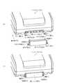
図1は、本実施形態のビデオカメラ10及びバッテリパック20の取付け面(ビデオカメラ10の後面10a及びバッテリパック20の前面20a)を示す正面図である。
図1に示すように、ビデオカメラ10は、バッテリパック20の取付け面となる後面10aの右上部にガイド突起11aを有し、左下部にガイド突起11b、右下部にガイド突起11cを有している。また、後面10aの中央部には、ロック凹部12及びロック爪13を有しており、ビデオカメラ10の側面からロック爪13の解除レバー14が飛び出している。さらにまた、後面10aの下部には、複数の柱状のコネクタピン31を配列した雄コネクタ部30を備えている。なお、ロック爪13は、通常は、バネ(図示せず)の付勢によってロック凹部12から突出している。そして、ロック爪13は、解除レバー14と連動しているので、バネの付勢に反して解除レバー14を押し込めば、ロック爪13がロック凹部12内に引き込まれるようになる。FIG. 1 is a front view showing mounting surfaces (the rear surface 10a of the
As shown in FIG. 1, the
一方、バッテリパック20は、充電可能なリチウム電池で構成されたバッテリ本体(図示せず)を内部に収納した偏平な直方体形状のものである。そして、バッテリパック20の取付け面となる前面20aは、その左上部にガイド溝21aが形成され、右下部にはガイド溝21b、左下部にはガイド溝21cが形成されている。また、バッテリパック20は、前面20aの中央部にロック凸部22及びロック溝23を有している。さらにまた、前面20aの下部には、ビデオカメラ10のの雄コネクタ部30に着脱自在に装着可能であり、バッテリ本体と電気的に接続された雌コネクタ部40を備えている。なお、前面20aの右上部には、ガイド溝21aと同様の溝が形成されている。 On the other hand, the
ここで、バッテリパック20のガイド溝21a、ガイド溝21b、及びガイド溝21cは、それぞれビデオカメラ10のガイド突起11a、ガイド突起11b、及びガイド突起11cと対応した位置にある。また、ロック凸部22及びロック溝23は、それぞれロック凹部12及びロック爪13と対応した位置にある。さらにまた、雌コネクタ部40は、雄コネクタ部30と対応した位置にある。そのため、ビデオカメラ10の後面10aに対し、バッテリパック20の前面20aを機械的及び電気的に着脱することができる。そして、ビデオカメラ10に装着されたバッテリパック20内のバッテリ本体(図示せず)がビデオカメラ10の駆動部(図示せず)の電源となる。 Here, the guide groove 21a, the guide groove 21b, and the guide groove 21c of the
ビデオカメラ10にバッテリパック20を装着するには、最初に、バッテリパック20を手でつかみ、雄コネクタ部30よりも雌コネクタ部40が上方に位置するようにして、ビデオカメラ10の後面10aにバッテリパック20の前面20aを重ね合わせる。この際、ガイド突起11aがガイド溝21aにはまり込み、ガイド突起11bがガイド溝21bにはまり込み、ガイド突起11cがガイド溝21cにはまり込むようにする。なお、ガイド溝21a、ガイド溝21b、及びガイド溝21cは、左右両側が傾斜面となっているので、ビデオカメラ10とバッテリパック20との位置が左右方向に少しずれていたとしても、後面10aと前面20aとがぴったりと合うようになる。 In order to attach the
次に、ビデオカメラ10の後面10aにバッテリパック20の前面20aを重ね合わせたまま、バッテリパック20を引き下げる。これにより、バッテリパック20は、ビデオカメラ10のガイド突起11a、ガイド突起11b、及びガイド突起11cに案内され、ロック凸部22がロック凹部12内に入り込むように誘導される。また、この際に、ロック凸部22は、ロック凹部12の左右のテーパ部分によって自動的にセンタリングされるとともに、ロック爪13がロック凹部12内に押し込められる。さらにまた、雌コネクタ部40が雄コネクタ部30に差し込まれて両者が結合するようになる。 Next, the
このようにして雌コネクタ部40と雄コネクタ部30とが結合し、コネクタピン31による電気的な接続が完了する位置になると、ロック爪13とロック溝23とが対応するようになる。これにより、それまでロック凸部22のテーパ部分によってロック凹部12内に押し込められていたロック爪13がバネ(図示せず)の付勢によって自動的に復帰し、ロック溝23にはまり込む。そのため、ビデオカメラ10とバッテリパック20とが電気的、機械的に接続され、バッテリパック20の装着が完了する。その結果、バッテリパック20からビデオカメラ10に電力が供給され、ビデオカメラ10の駆動部(図示せず)を電気的に駆動できるようになる。 In this way, when the
逆に、バッテリパック20をビデオカメラ10から取り外すには、ビデオカメラ10の側面から飛び出している解除レバー14を指で押し込めばよい。これにより、解除レバー14に連動してロック爪13がロック凹部12内に引き込まれるようになり、ロック溝23から外れる。そして、解除レバー14を押し込んだままバッテリパック20を手でつかみ、そのままビデオカメラ10の後面10aに沿ってバッテリパック20を引き上げる。その結果、バッテリパック20は、ガイド突起11a、ガイド突起11b、及びガイド突起11cに案内されながら上方に移動し、ロック凸部22がロック凹部12から外れるとともに、雌コネクタ部40が雄コネクタ部30から離脱する。したがって、ビデオカメラ10からバッテリパック20を取り外せるようになる。 Conversely, in order to remove the
このように、バッテリパック20は、ビデオカメラ10に対して着脱自在に装着可能となっている。そして、バッテリパック20を装着する際には、ガイド突起11aとガイド溝21a、ガイド突起11bとガイド溝21b、ガイド突起11cとガイド溝21cとがはまり合う。また、ロック凹部12の左右のテーパ部分によってロック凸部22がセンタリングされる。そのため、雄コネクタ部30と雌コネクタ部40とが位置合わせされることとなる。 Thus, the
しかし、雄コネクタ部30と雌コネクタ部40との間に位置ずれが生じることがある。このような場合には、雌コネクタ部40が雄コネクタ部30に差し込まれる際に、両者の位置ずれに起因する外力によってコネクタピン31に大きな荷重が作用する。そして、ビデオカメラ10に対するバッテリパック20の装着がくり返されると、最終的にコネクタピン31が疲労破壊してしまう。 However, misalignment may occur between the
また、バッテリパック20がビデオカメラ10に装着された後の両者の機械的結合は、ロック凹部12とロック凸部22(ロック爪13とロック溝23)とのはめ合いによって維持される。そして、雄コネクタ部30のコネクタピン31は、雌コネクタ部40に差し込まれた状態となっている。そのため、装着されたバッテリパック20をビデオカメラ10から引き離す方向(前面20aが後面10aから離れる方向)の外力が作用した場合には、ロック凹部12とロック凸部22とがはめ合っているとしても、コネクタピン31に大きな荷重が作用する。 Further, the mechanical coupling between the
さらにまた、バッテリパック20にコネクタピン31の配列方向の外力が作用した場合や、バッテリパック20にコネクタピン31の差込み方向の外力が作用した場合にも、コネクタピン31に大きな荷重が作用する。しかし、本実施形態の雄コネクタ部30及び雌コネクタ部40は、バッテリパック20に各方向の外力が作用したとしても、コネクタピン31に作用する荷重が大幅に軽減されるようになっている。 Furthermore, when an external force in the arrangement direction of the connector pins 31 acts on the
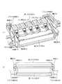
図2は、本実施形態のバッテリパック20に備えられた雌コネクタ部40と雄コネクタ部30との着脱状態を示す斜視図である。
また、図3は、本実施形態の雌コネクタ部40と雄コネクタ部30との関係を示す斜視図及び正面図である。
なお、雄コネクタ部30は、図1に示すビデオカメラ10の後面10aに取り付けられているが、図2では、ビデオカメラ10の図示を省略している。また、図3(a)では、雌コネクタ部40は、溝部43の平面で切り欠いた断面を図示し、雄コネクタ部30は、上部を取り除いた状態を図示している。FIG. 2 is a perspective view showing a detachable state of the
FIG. 3 is a perspective view and a front view showing the relationship between the
The
図2及び図3に示すように、雌コネクタ部40は、雄コネクタ部30に配列された複数の柱状のコネクタピン31(図3(a)参照)に対応するように列をなして配置され、各コネクタピン31をそれぞれ個別に差込み可能な複数のピン差込み口41と、両端のピン差込み口41よりも外側に形成され、各ピン差込み口41の奥行き方向に伸びる一対のコネクタ内壁42と、各コネクタ内壁42の内面にそれぞれ形成され、雄コネクタ部30側に設けられた突起部33がはまり合うように各ピン差込み口41の開口側から奥底側に向かうにつれて浅くなる一対の溝部43とを有している。なお、各溝部43は、各ピン差込み口41を通ってその奥行き方向に伸びる平面と平行な面から見て、三角形状となっている。そして、雄コネクタ部30の突起部33は、雌コネクタ部40の溝部43に対応する三角形状となっている。 As shown in FIGS. 2 and 3, the
また、雌コネクタ部40は、両端のピン差込み口41と各コネクタ内壁42との間に、各ピン差込み口41の配列方向に伸びる一対のコネクタ底面45(図3(a)参照)を有している。さらにまた、雌コネクタ部40は、両端のピン差込み口41よりも外側に、各ピン差込み口41の配列方向に伸びるとともに各溝部43の端面となる一対のコネクタ端面46を有している。そして、各コネクタ端面46は、突起部33が溝部43にはまり合わない場合に突起部33が当接する当接部47を備えている。 The
一方、雄コネクタ部30は、雌コネクタ部40に配列された複数のピン差込み口41に対応するように列をなして配置され、各ピン差込み口41にそれぞれ個別に差込み可能な複数の柱状のコネクタピン31(図3(a)参照)と、両端のコネクタピン31よりも外側に形成され、各コネクタピン31の長さ方向に伸びる一対のコネクタ外壁32(図2(a)参照)と、各コネクタ外壁32の外面にそれぞれ形成され、雌コネクタ部40側に設けられた溝部43にはまり合うように各コネクタピン31の先端側から根元側に向かうにつれて高くなる一対の突起部33とを有している。 On the other hand, the
ここで、雌コネクタ部40と雄コネクタ部30との位置があっている場合には、雌コネクタ部40を雄コネクタ部30に結合する際に、最初に、溝部43に突起部33がはまり込む。この際、溝部43は、三角形状であり、各ピン差込み口41の開口側が深くなっている。また、突起部33は、三角形状であり、各コネクタピン31の先端側が低くなっている。そのため、深い溝部43と低い突起部33とのはめ合いになるので、両者間に各ピン差込み口41の配列方向の位置ずれがあったとしても、その位置ずれを吸収できるようになる。 Here, when the positions of the
また、溝部43及び突起部33が三角形状となっているので、雌コネクタ部40と雄コネクタ部30との結合につれて、各ピン差込み口41の中心と各コネクタピン31(図3(a)参照)の中心とが互いに近づくようにセンタリングされる。そして、各ピン差込み口41に各コネクタピン31が差し込まれた状態になると、図2(b)及び図3(b)に示すように、突起部33の上下が溝部43によって拘束される。 Moreover, since the groove part 43 and the protrusion part 33 are triangular shape, the center of each pin insertion port 41 and each connector pin 31 (refer Fig.3 (a)) as the
したがって、雌コネクタ部40と雄コネクタ部30とが電気的に接続されるとともに、各溝部43は、本発明における第1拘束部として作用する。具体的には、各溝部43(第1拘束部)により、各ピン差込み口41を通ってその奥行き方向(図2(a)参照)に伸びる平面に垂直な方向の各コネクタピン31の動きが±0.22mm以内に抑えられる。なお、本実施形態の雌コネクタ部40及び雄コネクタ部30は、この方向の動きを±0.22mm以内に小さく抑えたとしても、各ピン差込み口41の配列方向の位置ずれを吸収できるので、雌コネクタ部40と雄コネクタ部30との結合は容易である。 Therefore, the
図4は、本実施形態の雌コネクタ部40と雄コネクタ部30との関係を示す平面図及び雄コネクタ部30の耐久性を示すグラフである。
図4(a)に示すように、雌コネクタ部40と雄コネクタ部30とが結合すると、雄コネクタ部30の先端部がコネクタ内壁42に沿ってコネクタ底面45に到達し、各ピン差込み口41(図3(a)参照)に各コネクタピン31(図3(a)参照)が差し込まれた状態となる。また、三角形状の溝部43と突起部33とは、三角形の斜辺同士が近接するようになる。FIG. 4 is a plan view showing the relationship between the
As shown in FIG. 4A, when the
したがって、各コネクタ底面45及び各溝部43は、各ピン差込み口41(図3(a)参照)の奥行き方向(図4の紙面の上方向)の各コネクタピン31(図3(a)参照)の動きを±0.22mm以内に抑えるように雄コネクタ部30側を拘束する(各コネクタ底面45及び各溝部43は、本発明における第2拘束部として作用する)。また、各コネクタ内壁42及び各溝部43は、各ピン差込み口41の配列方向(図4の紙面の左右方向)の各コネクタピン31の動きを±0.22mm以内に抑えるように雄コネクタ部30側を拘束する(各コネクタ内壁42及び各溝部43は、本発明における第3拘束部として作用する)。 Therefore, each connector bottom surface 45 and each groove portion 43 are connected to each connector pin 31 (see FIG. 3A) in the depth direction (upward direction in FIG. 4) of each pin insertion port 41 (see FIG. 3A). The
ここで、各コネクタピン31(図3(a)参照)の動きを±0.22mm以内に抑えれば、各コネクタピン31の破壊寿命を大幅に(ほぼ無限大まで)延ばせることが実験的に確認されている。具体的には、図4(b)に示すように、コネクタピン31に対して荷重をくり返し作用させたとき、その荷重が20Nであれば、コネクタピン31の破壊までのくり返し回数がほぼ100万回になる。また、荷重が20N以下であれば、くり返し回数が無限大に近くなる。そして、コネクタピン31の動きとコネクタピン31に作用する荷重との間には相関があり、その動きが±0.22mm以内であれば、荷重が20N以下となる。したがって、各コネクタピン31の動きが±0.22mm以内に抑えられた本実施形態の雌コネクタ部40及び雄コネクタ部30であれば、コネクタピン31がどの方向に動いたとしても、コネクタピン31が破壊されることはない。 Here, if the movement of each connector pin 31 (see FIG. 3A) is suppressed to within ± 0.22 mm, it is experimentally possible to extend the breakage life of each connector pin 31 significantly (to almost infinity). It has been confirmed. Specifically, as shown in FIG. 4B, when the load is repeatedly applied to the connector pin 31, if the load is 20 N, the number of repetitions until the connector pin 31 is broken is almost 1 million. Times. If the load is 20 N or less, the number of repetitions is close to infinity. There is a correlation between the movement of the connector pin 31 and the load acting on the connector pin 31, and if the movement is within ± 0.22 mm, the load is 20 N or less. Accordingly, if the movement of each connector pin 31 is suppressed within ± 0.22 mm, the connector pin 31 can be moved in any direction as long as the connector pin 31 moves in any direction. Will not be destroyed.
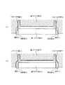
図5は、本実施形態の雌コネクタ部40と雄コネクタ部30との位置ずれ状態を示す斜視図及び正面図である。
図5に示すように、コネクタ端面46は、当接部47を備えている。そして、各溝部43と各突起部33との位置が合わないときは、各ピン差込み口41に各コネクタピン31が差し込まれる前に、突起部33の先端部が当接部47に当接する。そのため、各コネクタピン31が雌コネクタ部40に衝突しなくなるので、コネクタピン31の破壊を未然に防止することができる。FIG. 5 is a perspective view and a front view showing a misalignment state between the
As shown in FIG. 5, the connector end surface 46 includes a
また、当接部47は、溝部43からコネクタ端面46の下面に向かう半円状になっている。そのため、当接部47に当接した突起部33は、溝部43の反対側に逃げるようになる。したがって、各溝部43と各突起部33との位置が合っていないことを容易に把握できる。なお、コネクタ端面46の下面から溝部43に向かう半円状の当接部とすれば、各溝部43と各突起部33との位置が合っていないときに、各突起部33を各溝部43に誘導することができる。 Further, the
図6は、他の実施形態の雌コネクタ部50(雌コネクタ部70)と雄コネクタ部30(雄コネクタ部60)との関係を示す平面図である。
図6(a)に示す構造は、図4(a)に示す構造と同じ雄コネクタ部30を備えるが、別形態の雌コネクタ部50が結合するようにしたものである。この雌コネクタ部50は、一対のコネクタ内壁52の内面にそれぞれ溝部53が形成されている。そして、各溝部53は、雄コネクタ部30側に設けられた突起部33がはまり合うように開口側から奥底側に向かうにつれて浅くなる。具体的には、平面視で、図6(a)に示すような放物線状に凹んだ溝部53となっている。FIG. 6 is a plan view showing the relationship between the female connector part 50 (female connector part 70) and the male connector part 30 (male connector part 60) according to another embodiment.
The structure shown in FIG. 6A includes the same
このような溝部53であっても、雌コネクタ部50を雄コネクタ部30に結合する際には、最初に、溝部53の深い側と突起部33の低い側とのはめ合いになる。そのため、両者間に多少の位置ずれがあったとしても、その位置ずれを吸収できる。したがって、雌コネクタ部50と雄コネクタ部30とを電気的に容易に接続できるだけでなく、各溝部53にはめ込まれた各突起部33により、雄コネクタ部30側を拘束できる。 Even in such a groove portion 53, when the
一方、図6(b)に示す構造は、さらに別形態の雌コネクタ部70とするとともに、この雌コネクタ部70に合わせた形状の雄コネクタ部60としたものである。具体的には、雌コネクタ部70の溝部73及び雄コネクタ部60の突起部63は、図6(b)に示すように、平面視で、奥行き方向に伸びる直線と斜辺とによって構成されている。そして、この斜辺により、溝部73は、奥底側に向かうにつれて浅くなる。また、突起部63は、奥底側に向かうにつれて高くなる。 On the other hand, the structure shown in FIG. 6 (b) is a
このような溝部73及び突起部63であっても、雌コネクタ部70を雄コネクタ部60に結合する際には、最初に、溝部73の深い側と突起部63の低い側とのはめ合いになる。そのため、両者間に多少の位置ずれがあったとしても、その位置ずれを吸収できる。したがって、雌コネクタ部70と雄コネクタ部60とを電気的に容易に接続できるだけでなく、各溝部73にはめ込まれた各突起部63により、雄コネクタ部30側を拘束できる。 Even in the case of such a groove 73 and the protrusion 63, when the
図7は、さらに他の実施形態の雌コネクタ部90と雄コネクタ部80との関係を示す平面図及び正面図である。
図7に示す雌コネクタ部90は、各コネクタ内壁92の内面にそれぞれ形成され、雄コネクタ部80側に設けられた溝部83にはまり合うように奥底側に向かうにつれて高くなる一対の突起部93を有している。そして、突起部93は、図7(a)に示すように、平面視で、三角形状となっている。FIG. 7 is a plan view and a front view showing the relationship between the female connector portion 90 and the male connector portion 80 of still another embodiment.
The female connector portion 90 shown in FIG. 7 is formed on the inner surface of each connector inner wall 92, and has a pair of protrusions 93 that become higher toward the bottom so as to fit into the groove portion 83 provided on the male connector portion 80 side. Have. As shown in FIG. 7A, the protrusion 93 has a triangular shape in plan view.
このような突起部93及び溝部83であっても、雌コネクタ部90を雄コネクタ部80に結合する際には、最初に、突起部93の低い側と溝部83とのはめ合いになる。そのため、両者間に多少の位置ずれがあったとしても、その位置ずれを吸収できる。したがって、雌コネクタ部90と雄コネクタ部80とを電気的に容易に接続できるだけでなく、各溝部83にはめ込まれた各突起部93により、雄コネクタ部80側を拘束できる。 Even with the projection 93 and the groove 83, when the female connector 90 is coupled to the male connector 80, the lower side of the projection 93 and the groove 83 are first fitted. Therefore, even if there is a slight misalignment between them, the misalignment can be absorbed. Therefore, not only can the female connector portion 90 and the male connector portion 80 be electrically connected easily, but the male connector portion 80 side can be constrained by the projections 93 fitted in the respective groove portions 83.
図8は、本実施形態のアダプタパック100を示す斜視図である。
図8に示すアダプタパック100は、商用電源の電力を入力し、ビデオカメラ10(図1参照)に合わせた形式の電力を出力する。そして、ビデオカメラ10に設けられた雄コネクタ部30aに着脱自在に装着可能な雌コネクタ部40aを備えている。具体的には、雌コネクタ部40aは、雄コネクタ部30a側に設けられた突起部33aがはまり合うように奥底側に向かうにつれて浅くなる一対の溝部43aを有している。また、雄コネクタ部30aは、雌コネクタ部40aに設けられた溝部43aにはまり合うように高くなる一対の突起部33aを有している。そのため、ビデオカメラ10(雄コネクタ部30a)にアダプタパック100(雌コネクタ部40a)を容易に装着できるだけでなく、各溝部43aにはめ込まれた各突起部33aにより、雄コネクタ部30a側を拘束できる。FIG. 8 is a perspective view showing the
The
さらに、このアダプタパック100は、雌コネクタ部40aが設けられた側と反対側の面に雄コネクタ部30bを備えている。そして、雄コネクタ部30bは、バッテリパック20の雌コネクタ部40bに設けられた溝部43bにはまり合うように高くなる一対の突起部33bを有している。そのため、アダプタパック100(雄コネクタ部30b)にバッテリパック20(雌コネクタ部40b)を容易に装着できる。そして、アダプタパック100からビデオカメラ10(図1参照)に電力を供給すると同時に、バッテリパック20を充電できる。 Furthermore, the
以上、本発明の実施形態について説明したが、本発明は、上述した実施形態に限定されることなく、例えば、以下のような種々の変形が可能である。
(1)雌コネクタ部40の溝部43は、各ピン差込み口41を通ってその奥行き方向に伸びる平面と平行な面から見て、三角形状となっている。しかし、溝部は、各ピン差込み口41の開口側から奥底側に向かうにつれて浅くなる形状であれば、角がいくつある多角形状であってもよい。また、溝部は、平面視で、傾斜角が異なる複数の直線を曲線で結んだ形状等であってもよい。The embodiment of the present invention has been described above. However, the present invention is not limited to the above-described embodiment, and various modifications such as the following are possible.
(1) The groove portion 43 of the
(2)上記の実施形態では、電気機器としてビデオカメラ10を例に挙げ、ビデオカメラ10に雄コネクタ部30を備えるとともに、バッテリパック20に雌コネクタ部40を備えるようにした。しかし、ビデオカメラ側を雌コネクタ部とし、バッテリパック側を雄コネクタ部としてもよい。また、雄コネクタ部や雌コネクタ部は、ビデオカメラに限らず、デジタルカメラ、携帯電話等の各種の電気機器に適用できる。 (2) In the above embodiment, the
10 ビデオカメラ(電気機器)
20 バッテリパック(バッテリ本体)
30 雄コネクタ部
31 コネクタピン
32 コネクタ外壁
33 突起部
40 雌コネクタ部
41 ピン差込み口
42 コネクタ内壁(第3拘束部)
43 溝部(第1拘束部、第2拘束部、第3拘束部)
45 コネクタ底面(第2拘束部)
46 コネクタ端面
47 当接部
50 雌コネクタ部
52 コネクタ内壁
53 溝部
60 雄コネクタ部
63 突起部
70 雌コネクタ部
72 コネクタ内壁
73 溝部
80 雄コネクタ部
83 溝部
90 雌コネクタ部
92 コネクタ内壁
93 突起部
100 アダプタパック(アダプタ本体)10 Video camera (electric equipment)
20 Battery pack (Battery body)
30 Male connector portion 31 Connector pin 32 Connector outer wall 33
43 Groove (first restraint, second restraint, third restraint)
45 Connector bottom (second restraint)
46 connector end face 47
Claims (8)
Translated fromJapanese両端の前記ピン差込み口よりも外側に形成され、各前記ピン差込み口の奥行き方向に伸びる一対のコネクタ内壁と、
各前記コネクタ内壁の内面にそれぞれ形成され、前記雄コネクタ部側に設けられた突起部がはまり合うように各前記ピン差込み口の開口側から奥底側に向かうにつれて浅くなる一対の溝部と、
両端の前記ピン差込み口よりも外側に形成され、各前記ピン差込み口の配列方向に伸びるとともに各前記溝部の端面となる一対のコネクタ端面と、を有し、
各前記コネクタ端面は、各前記溝部と各前記突起部との位置が合わないとき、各前記ピン差込み口に各前記コネクタピンが差し込まれる前に、前記突起部の少なくとも一方に当接する当接部を備え、
前記当接部は、前記溝部から前記コネクタ端面の下面に向かう半円状に形成されている
雌コネクタ構造。A plurality of pin insertion openings arranged in rows to correspond to the plurality of columnar connector pins arranged in the male connector portion, and each of the connector pins can be individually inserted;
A pair of connector inner walls formed outside the pin insertion openings at both ends and extending in the depth direction of each of the pin insertion openings;
A pair of grooves that are formed on the inner surface of each inner wall of each connector and become shallower from the opening side of each pin insertion port toward the bottom so that the protrusions provided on the male connector portion side fit together,
A pair of connector end surfaces that are formed outside the pin insertion ports at both ends, extend in the arrangement direction of the pin insertion ports and serve as end surfaces of the groove portions, and
Each connector end surface is in contact with at least one of the protrusions before each connector pin is inserted into each pin insertion port when the position of each groove and each protrusion does not match. With
The contact portion is a female connector structureformed in a semicircular shape from the groove portion toward the lower surface of the connector end surface .
各前記溝部は、各前記ピン差込み口を通ってその奥行き方向に伸びる平面に平行な面から見て、三角形状である
雌コネクタ構造。The female connector structure according to claim 1,
Each said groove part is triangular shape seeing from the surface parallel to the plane extended through the said pin insertion port in the depth direction, Each female connector structure.
各前記溝部は、各前記ピン差込み口に各前記コネクタピンを差し込んだ状態で、各前記ピン差込み口を通ってその奥行き方向に伸びる平面に垂直な方向の各前記コネクタピンの動きを±0.22mm以内に抑えるように前記突起部を拘束するための第1拘束部を備える
雌コネクタ構造。In the female connector structure according to claim 1or 2 ,
Each groove portion has a movement of each connector pin in a direction perpendicular to a plane extending in the depth direction through each pin insertion port in a state where each connector pin is inserted into each pin insertion port. A female connector structure comprising a first restraining portion for restraining the protrusion so as to be suppressed within 22 mm.
両端の前記ピン差込み口と各前記コネクタ内壁との間に形成され、各前記ピン差込み口の配列方向に伸びる一対のコネクタ底面を有し、
各前記コネクタ底面又は各前記溝部は、各前記ピン差込み口に各前記コネクタピンを差し込んだ状態で、各前記ピン差込み口の奥行き方向の各前記コネクタピンの動きを±0.22mm以内に抑えるように前記雄コネクタ部側を拘束するための第2拘束部を備え、
各前記コネクタ内壁又は各前記溝部は、各前記ピン差込み口に各前記コネクタピンを差し込んだ状態で、各前記ピン差込み口の配列方向の各前記コネクタピンの動きを±0.22mm以内に抑えるように前記雄コネクタ部側を拘束するための第3拘束部を備える
雌コネクタ構造。In the female connector structure according to claim3 ,
A pair of connector bottom surfaces formed between the pin insertion openings at both ends and the inner walls of the connectors, and extending in the arrangement direction of the pin insertion openings;
Each connector bottom surface or each groove portion suppresses movement of each connector pin in the depth direction of each pin insertion port within ± 0.22 mm in a state where each connector pin is inserted into each pin insertion port. A second restraining portion for restraining the male connector portion side,
Each connector inner wall or each groove portion suppresses movement of each connector pin in the arrangement direction of each pin insertion port within ± 0.22 mm in a state where each connector pin is inserted into each pin insertion port. A female connector structure comprising a third restraining portion for restraining the male connector portion side.
前記電気機器の雄コネクタ部に着脱自在に装着可能であり、前記バッテリ本体と電気的に接続された雌コネクタ部と
を備え、
前記雌コネクタ部は、
前記雄コネクタ部に配列された複数の柱状のコネクタピンに対応するように列をなして配置され、各前記コネクタピンをそれぞれ個別に差込み可能な複数のピン差込み口と、
両端の前記ピン差込み口よりも外側に形成され、各前記ピン差込み口の奥行き方向に伸びる一対のコネクタ内壁と、
各前記コネクタ内壁の内面にそれぞれ形成され、前記雄コネクタ部側に設けられた突起部がはまり合うように各前記ピン差込み口の開口側から奥底側に向かうにつれて浅くなる一対の溝部と、
両端の前記ピン差込み口よりも外側に形成され、各前記ピン差込み口の配列方向に伸びるとともに各前記溝部の端面となる一対のコネクタ端面と、を有し、
各前記コネクタ端面は、各前記溝部と各前記突起部との位置が合わないとき、各前記ピン差込み口に各前記コネクタピンが差し込まれる前に、前記突起部の少なくとも一方に当接する当接部を備え、
前記当接部は、前記溝部から前記コネクタ端面の下面に向かう半円状に形成されている
バッテリ。A battery body serving as a power source for external electrical equipment;
A male connector part of the electrical device, which can be detachably mounted, and includes a female connector part electrically connected to the battery body,
The female connector part is
A plurality of pin insertion openings arranged in rows to correspond to the plurality of columnar connector pins arranged in the male connector portion, and each of the connector pins can be individually inserted,
A pair of connector inner walls formed outside the pin insertion openings at both ends and extending in the depth direction of each of the pin insertion openings;
A pair of grooves that are formed on the inner surface of each inner wall of each connector and become shallower from the opening side of each pin insertion port toward the bottom so that the protrusions provided on the male connector portion side fit together,
A pair of connector end surfaces that are formed outside the pin insertion ports at both ends, extend in the arrangement direction of the pin insertion ports and serve as end surfaces of the groove portions, and
Each connector end surface is in contact with at least one of the protrusions before each connector pin is inserted into each pin insertion port when the position of each groove and each protrusion does not match. With
The batteryis formed in a semicircular shape from the groove toward the lower surface of the connector end surface .
前記バッテリ本体は、前記雌コネクタ部を介して外部の電源から充電可能である
バッテリ。The battery according to claim5 , wherein
The battery body can be charged from an external power source through the female connector portion.
前記電気機器は、ビデオカメラである
バッテリ。The battery according to claim5 or 6 ,
The electric device is a video camera battery.
前記電気機器の雄コネクタ部に着脱自在に装着可能であり、前記アダプタ本体と電気的に接続された雌コネクタ部と
を備え、
前記雌コネクタ部は、
前記雄コネクタ部に配列された複数の柱状のコネクタピンに対応するように列をなして配置され、各前記コネクタピンをそれぞれ個別に差込み可能な複数のピン差込み口と、
両端の前記ピン差込み口よりも外側に形成され、各前記ピン差込み口の奥行き方向に伸びる一対のコネクタ内壁と、
各前記コネクタ内壁の内面にそれぞれ形成され、前記雄コネクタ部側に設けられた突起部がはまり合うように各前記ピン差込み口の開口側から奥底側に向かうにつれて浅くなる一対の溝部と、
両端の前記ピン差込み口よりも外側に形成され、各前記ピン差込み口の配列方向に伸びるとともに各前記溝部の端面となる一対のコネクタ端面と、を有し、
各前記コネクタ端面は、各前記溝部と各前記突起部との位置が合わないとき、各前記ピン差込み口に各前記コネクタピンが差し込まれる前に、前記突起部の少なくとも一方に当接する当接部を備え、
前記当接部は、前記溝部から前記コネクタ端面の下面に向かう半円状に形成されている
アダプタ。An adapter body that inputs the power of commercial power and outputs power in a format that matches the external electrical equipment,
A male connector portion of the electrical device that is detachably attachable, and includes a female connector portion electrically connected to the adapter body,
The female connector part is
A plurality of pin insertion openings arranged in rows to correspond to the plurality of columnar connector pins arranged in the male connector portion, and each of the connector pins can be individually inserted,
A pair of connector inner walls formed outside the pin insertion openings at both ends and extending in the depth direction of each of the pin insertion openings;
A pair of grooves that are formed on the inner surface of each inner wall of each connector and become shallower from the opening side of each pin insertion port toward the bottom so that the protrusions provided on the male connector portion side fit together,
A pair of connector end surfaces that are formed outside the pin insertion ports at both ends, extend in the arrangement direction of the pin insertion ports and serve as end surfaces of the groove portions, and
Each connector end surface is in contact with at least one of the protrusions before each connector pin is inserted into each pin insertion port when the position of each groove and each protrusion does not match. With
The abutment portion is an adapterformed in a semicircular shape from the groove portion toward the lower surface of the connector end surface .
Priority Applications (6)
| Application Number | Priority Date | Filing Date | Title |
|---|---|---|---|
| JP2008166310AJP5088249B2 (en) | 2008-06-25 | 2008-06-25 | Female connector structure, battery, and adapter |
| EP20090251552EP2139056A1 (en) | 2008-06-25 | 2009-06-12 | Female connector structure, male connector structure, battery, adaptor and electric device |
| TW098120465ATWI373892B (en) | 2008-06-25 | 2009-06-18 | Female connector structure, male connector structure, battery, adaptor and electric device |
| US12/489,533US8029311B2 (en) | 2008-06-25 | 2009-06-23 | Female connector structure, male connector structure, battery, adapter and electric device |
| KR1020090056631AKR20100002176A (en) | 2008-06-25 | 2009-06-24 | Female connector structure, male connector structure, battery, adaptor and electric device |
| CN2009101494915ACN101615745B (en) | 2008-06-25 | 2009-06-25 | Female connector structure, male connector structure, battery, adapter and electric device |
Applications Claiming Priority (1)
| Application Number | Priority Date | Filing Date | Title |
|---|---|---|---|
| JP2008166310AJP5088249B2 (en) | 2008-06-25 | 2008-06-25 | Female connector structure, battery, and adapter |
Publications (2)
| Publication Number | Publication Date |
|---|---|
| JP2010010944A JP2010010944A (en) | 2010-01-14 |
| JP5088249B2true JP5088249B2 (en) | 2012-12-05 |
Family
ID=40852439
Family Applications (1)
| Application Number | Title | Priority Date | Filing Date |
|---|---|---|---|
| JP2008166310AActiveJP5088249B2 (en) | 2008-06-25 | 2008-06-25 | Female connector structure, battery, and adapter |
Country Status (6)
| Country | Link |
|---|---|
| US (1) | US8029311B2 (en) |
| EP (1) | EP2139056A1 (en) |
| JP (1) | JP5088249B2 (en) |
| KR (1) | KR20100002176A (en) |
| CN (1) | CN101615745B (en) |
| TW (1) | TWI373892B (en) |
Families Citing this family (11)
| Publication number | Priority date | Publication date | Assignee | Title |
|---|---|---|---|---|
| US7918685B1 (en) | 2010-04-01 | 2011-04-05 | CableJive LLC | Cable assembly for mobile media devices |
| GB2494189A (en)* | 2011-09-02 | 2013-03-06 | Pag Ltd | Battery coupling arrangement |
| GB2526005B (en) | 2011-09-02 | 2016-04-06 | Pag Ltd | Battery management system, method and battery |
| US10027060B2 (en)* | 2012-10-26 | 2018-07-17 | Sony Corporation | Adapter device and electronic device |
| US9653719B2 (en) | 2013-10-04 | 2017-05-16 | Pag Ltd. | Battery |
| CN104578231B (en)* | 2013-10-12 | 2017-12-01 | 苏州宝时得电动工具有限公司 | Charger and charging system |
| US10637264B2 (en)* | 2014-09-24 | 2020-04-28 | Powertec Solutions International Llc | Portable switching power supply with attachable battery pack and enclosure |
| KR102341784B1 (en)* | 2015-04-29 | 2021-12-22 | 주식회사 탑 엔지니어링 | Board for testing camera module |
| KR102280995B1 (en)* | 2017-11-16 | 2021-07-22 | 주식회사 엘지에너지솔루션 | Battery module comprising housing with connector |
| JP7265461B2 (en) | 2019-09-26 | 2023-04-26 | 住友電装株式会社 | Power supply device and branch connector device |
| CN111659546B (en)* | 2020-04-24 | 2024-09-06 | 青岛海特生物医疗有限公司 | Centrifugal machine |
Family Cites Families (43)
| Publication number | Priority date | Publication date | Assignee | Title |
|---|---|---|---|---|
| US2911612A (en)* | 1956-01-26 | 1959-11-03 | Jackson Anton | Printed circuit contact receptacles |
| US4431245A (en)* | 1982-01-11 | 1984-02-14 | Christie Electric Corporation | Connector for battery pack |
| US4578628A (en)* | 1985-01-04 | 1986-03-25 | Motorola Inc. | Portable battery powered electrical apparatus with improved battery pack protected against inadvertent short circuit of the battery terminals |
| US4616169A (en)* | 1985-04-08 | 1986-10-07 | Scovill Inc. | Battery-powered appliance |
| US4590943A (en)* | 1985-04-19 | 1986-05-27 | Physio-Control Corporation | System for providing power to portable defibrillator |
| JPH0817101B2 (en)* | 1990-03-23 | 1996-02-21 | 矢崎総業株式会社 | Low insertion / removal force multi-pole electrical connector assembly |
| US5009384A (en)* | 1990-06-29 | 1991-04-23 | Inter-Link Communciations Inc. | Overhead support system for TV monitors |
| JP3303305B2 (en)* | 1991-08-23 | 2002-07-22 | ソニー株式会社 | Video camera device connection device |
| US5369565A (en)* | 1991-10-04 | 1994-11-29 | Innova Electronics Corp. | Modular power supply system |
| JP3508188B2 (en)* | 1993-11-15 | 2004-03-22 | ソニー株式会社 | Camera accessories |
| JP3399055B2 (en) | 1993-11-15 | 2003-04-21 | ソニー株式会社 | Mounting mechanism |
| US5605150A (en)* | 1994-11-04 | 1997-02-25 | Physio-Control Corporation | Electrical interface for a portable electronic physiological instrument having separable components |
| JP3404951B2 (en) | 1994-12-26 | 2003-05-12 | ソニー株式会社 | Battery device |
| JPH11511891A (en)* | 1995-02-08 | 1999-10-12 | ザ ウィタカー コーポレーション | Flange plug connector to mate with right angle connector |
| US5554042A (en)* | 1995-02-28 | 1996-09-10 | Trimble Navigation, Limited | Resilient body electrical connector system |
| DE19512255A1 (en)* | 1995-03-31 | 1996-10-02 | Siemens Ag | Arrangement for receiving an insert body in a receiving body |
| US6171125B1 (en)* | 1997-02-12 | 2001-01-09 | Rostra Precision Controls, Inc. | Electrical connector for solenoids on vehicle transmissions |
| TW328403U (en)* | 1997-05-09 | 1998-03-11 | Formosa Electronicindustries Inc | Ac/dc power supplier having a replaceable plug |
| US6086419A (en)* | 1998-01-28 | 2000-07-11 | The Whitaker Corporation | Electrical connector assembly |
| US6702604B1 (en)* | 1999-08-23 | 2004-03-09 | Jerry Moscovitch | Universal quick connector apparatus for an LCD monitor |
| JP4174149B2 (en)* | 1999-12-01 | 2008-10-29 | 矢崎総業株式会社 | Half-mating prevention connector |
| US6590563B1 (en)* | 2000-07-21 | 2003-07-08 | Hewlett-Packard Development Company, L.P. | Pointing device having two parts and method of use therefor |
| US6525511B2 (en)* | 2000-08-11 | 2003-02-25 | Milwaukee Electric Tool Corporation | Adapter for a power tool battery |
| JP3478808B2 (en)* | 2001-05-28 | 2003-12-15 | イリソ電子工業株式会社 | Electrical connector |
| US6729413B2 (en)* | 2001-08-24 | 2004-05-04 | Black & Decker Inc. | Power tool with battery pack ejector |
| JP3693110B2 (en) | 2002-02-25 | 2005-09-07 | ソニー株式会社 | power cable |
| GB2392002B (en)* | 2002-08-12 | 2004-10-13 | Choon Nang Elec Appl Mfy Ltd | Rechargeable battery pack |
| JP3528844B2 (en) | 2002-10-07 | 2004-05-24 | ソニー株式会社 | Mounting mechanism, battery and adapter on the mounting surface |
| JP3632688B2 (en) | 2002-10-07 | 2005-03-23 | ソニー株式会社 | Battery pack, adapter and camera accessories |
| GB0306486D0 (en)* | 2003-03-21 | 2003-04-23 | Black & Decker Inc | Cordless hand held power tool with power accessory |
| US7125270B2 (en)* | 2003-05-28 | 2006-10-24 | Eastway Fair Trade Company Limited | Slide type battery ejection mechanism |
| TWM243342U (en)* | 2003-08-06 | 2004-09-11 | Mobiletron Electronics Co Ltd | Electric tool |
| US20050226741A1 (en)* | 2004-04-08 | 2005-10-13 | Wen-Sheng Huang | Engagement terminals for DC power pack and copressor |
| CN2762964Y (en)* | 2005-01-10 | 2006-03-08 | 南京德朔实业有限公司 | Electric tool power supplied by battery |
| TW200627722A (en)* | 2005-01-17 | 2006-08-01 | Sunonwealth Electruc Machine Industry Co Ltd | Plug assembly structure of a wire terminal (2) |
| JP4427748B2 (en)* | 2005-02-28 | 2010-03-10 | 住友電装株式会社 | connector |
| DE102005009098A1 (en)* | 2005-02-28 | 2006-09-07 | Yamaichi Electronics Deutschland Gmbh | Circuit board connector, has housing and protrusions for guiding complementary connector so that contact elements are aligned |
| JP2007018993A (en)* | 2005-06-07 | 2007-01-25 | Kyocera Elco Corp | Connector and portable terminal |
| JP4262708B2 (en)* | 2005-09-26 | 2009-05-13 | 住友電装株式会社 | Board connector |
| DE102006018009A1 (en)* | 2006-04-07 | 2007-10-11 | Robert Bosch Gmbh | battery Pack |
| US7659694B2 (en)* | 2006-10-02 | 2010-02-09 | Snap-On Incorporated | Self-aligning terminal block for battery pack |
| USD568239S1 (en)* | 2006-10-13 | 2008-05-06 | Hitachi Koki Co., Ltd. | Battery pack |
| JP2008166310A (en) | 2006-12-26 | 2008-07-17 | Toshiba Corp | Solder printing mask, printed wiring board, and circuit board manufacturing method |
- 2008
- 2008-06-25JPJP2008166310Apatent/JP5088249B2/enactiveActive
- 2009
- 2009-06-12EPEP20090251552patent/EP2139056A1/ennot_activeWithdrawn
- 2009-06-18TWTW098120465Apatent/TWI373892B/ennot_activeIP Right Cessation
- 2009-06-23USUS12/489,533patent/US8029311B2/enactiveActive
- 2009-06-24KRKR1020090056631Apatent/KR20100002176A/ennot_activeCeased
- 2009-06-25CNCN2009101494915Apatent/CN101615745B/ennot_activeExpired - Fee Related
Also Published As
| Publication number | Publication date |
|---|---|
| CN101615745B (en) | 2013-01-02 |
| CN101615745A (en) | 2009-12-30 |
| EP2139056A1 (en) | 2009-12-30 |
| TWI373892B (en) | 2012-10-01 |
| TW201014086A (en) | 2010-04-01 |
| KR20100002176A (en) | 2010-01-06 |
| US8029311B2 (en) | 2011-10-04 |
| US20090325425A1 (en) | 2009-12-31 |
| JP2010010944A (en) | 2010-01-14 |
Similar Documents
| Publication | Publication Date | Title |
|---|---|---|
| JP5088249B2 (en) | Female connector structure, battery, and adapter | |
| TWI632742B (en) | Electrical connector for circuit substrate | |
| JP6039473B2 (en) | connector | |
| CN102222831B (en) | Connector that enables connection between circuit boards with excellent space efficiency | |
| CN104466533B (en) | Board-connecting electrical connector device | |
| CN103918139B (en) | Lever-fitting-type connector | |
| CN101511549A (en) | Adapter for a power tool battery pack | |
| JP2006339154A (en) | Connector having lock lever | |
| JP4458024B2 (en) | Electric tool | |
| CN110556668A (en) | Connector with a locking member | |
| JP2013033606A (en) | Lever fitting type connector unit | |
| JP2015015126A (en) | Flat conductor electrical connector | |
| TW201424136A (en) | Flat type electrical connector for conductor | |
| CN102160241B (en) | Electrical connector | |
| CN105103379B (en) | Connector assembly | |
| JP6352676B2 (en) | connector | |
| TWI569534B (en) | Electrical connector assembly | |
| JP2007329048A (en) | connector | |
| EP2693245B1 (en) | Connector | |
| ES2871077T3 (en) | Electronics module removal feedback system | |
| US7150637B2 (en) | Battery chamber structure | |
| JP2019114361A (en) | Connector housing | |
| ES2350602T3 (en) | ELECTRICAL CONNECTOR ASSEMBLY. | |
| JP2020161323A (en) | Connector housing | |
| JP2008177096A (en) | Connector locking mechanism |
Legal Events
| Date | Code | Title | Description |
|---|---|---|---|
| RD02 | Notification of acceptance of power of attorney | Free format text:JAPANESE INTERMEDIATE CODE: A7422 Effective date:20100902 | |
| A621 | Written request for application examination | Free format text:JAPANESE INTERMEDIATE CODE: A621 Effective date:20110525 | |
| A977 | Report on retrieval | Free format text:JAPANESE INTERMEDIATE CODE: A971007 Effective date:20120419 | |
| A131 | Notification of reasons for refusal | Free format text:JAPANESE INTERMEDIATE CODE: A131 Effective date:20120424 | |
| A521 | Request for written amendment filed | Free format text:JAPANESE INTERMEDIATE CODE: A523 Effective date:20120622 | |
| TRDD | Decision of grant or rejection written | ||
| A01 | Written decision to grant a patent or to grant a registration (utility model) | Free format text:JAPANESE INTERMEDIATE CODE: A01 Effective date:20120814 | |
| A01 | Written decision to grant a patent or to grant a registration (utility model) | Free format text:JAPANESE INTERMEDIATE CODE: A01 | |
| A61 | First payment of annual fees (during grant procedure) | Free format text:JAPANESE INTERMEDIATE CODE: A61 Effective date:20120827 | |
| FPAY | Renewal fee payment (event date is renewal date of database) | Free format text:PAYMENT UNTIL: 20150921 Year of fee payment:3 | |
| R151 | Written notification of patent or utility model registration | Ref document number:5088249 Country of ref document:JP Free format text:JAPANESE INTERMEDIATE CODE: R151 | |
| FPAY | Renewal fee payment (event date is renewal date of database) | Free format text:PAYMENT UNTIL: 20150921 Year of fee payment:3 | |
| R250 | Receipt of annual fees | Free format text:JAPANESE INTERMEDIATE CODE: R250 | |
| R250 | Receipt of annual fees | Free format text:JAPANESE INTERMEDIATE CODE: R250 | |
| R250 | Receipt of annual fees | Free format text:JAPANESE INTERMEDIATE CODE: R250 | |
| R250 | Receipt of annual fees | Free format text:JAPANESE INTERMEDIATE CODE: R250 | |
| R250 | Receipt of annual fees | Free format text:JAPANESE INTERMEDIATE CODE: R250 | |
| R250 | Receipt of annual fees | Free format text:JAPANESE INTERMEDIATE CODE: R250 |