JP5088074B2 - Parking support apparatus and method - Google Patents
Parking support apparatus and methodDownload PDFInfo
- Publication number
- JP5088074B2 JP5088074B2JP2007257986AJP2007257986AJP5088074B2JP 5088074 B2JP5088074 B2JP 5088074B2JP 2007257986 AJP2007257986 AJP 2007257986AJP 2007257986 AJP2007257986 AJP 2007257986AJP 5088074 B2JP5088074 B2JP 5088074B2
- Authority
- JP
- Japan
- Prior art keywords
- parking
- vehicle
- image
- initial
- target position
- Prior art date
- Legal status (The legal status is an assumption and is not a legal conclusion. Google has not performed a legal analysis and makes no representation as to the accuracy of the status listed.)
- Active
Links
Images


Classifications
- B—PERFORMING OPERATIONS; TRANSPORTING
- B62—LAND VEHICLES FOR TRAVELLING OTHERWISE THAN ON RAILS
- B62D—MOTOR VEHICLES; TRAILERS
- B62D15/00—Steering not otherwise provided for
- B62D15/02—Steering position indicators ; Steering position determination; Steering aids
- B62D15/027—Parking aids, e.g. instruction means
- B62D15/0275—Parking aids, e.g. instruction means by overlaying a vehicle path based on present steering angle over an image without processing that image
- B—PERFORMING OPERATIONS; TRANSPORTING
- B62—LAND VEHICLES FOR TRAVELLING OTHERWISE THAN ON RAILS
- B62D—MOTOR VEHICLES; TRAILERS
- B62D15/00—Steering not otherwise provided for
- B62D15/02—Steering position indicators ; Steering position determination; Steering aids
- B62D15/027—Parking aids, e.g. instruction means
- B62D15/028—Guided parking by providing commands to the driver, e.g. acoustically or optically
Landscapes
- Engineering & Computer Science (AREA)
- Chemical & Material Sciences (AREA)
- Combustion & Propulsion (AREA)
- Transportation (AREA)
- Mechanical Engineering (AREA)
- Closed-Circuit Television Systems (AREA)
- Traffic Control Systems (AREA)
- Image Processing (AREA)
- Steering Control In Accordance With Driving Conditions (AREA)
- Image Analysis (AREA)
- Control Of Driving Devices And Active Controlling Of Vehicle (AREA)
Abstract
Description
Translated fromJapanese本発明は、車両の運転者に周囲状況を表す画像を提示することによって、自車両を駐車させる運転操作を支援する駐車支援装置及び方法に関する。 The present invention relates to a parking assistance apparatus and method for assisting a driving operation for parking a host vehicle by presenting an image representing a surrounding situation to a driver of the vehicle.
従来から、車両周辺を複数のカメラにより撮影し、得られた画像を座標変換してあたかも仮想視点である上空から車両を眺めた画像である俯瞰画像を用いた駐車支援装置が知られている(下記の特許文献1参照)。このような駐車支援装置は、駐車可能なスペースである駐車目標位置情報の検出、駐車目標位置に車両を移動させるために経由すべき位置である駐車初期位置情報の演算、及び車両の走行予測軌跡線の演算を行い、本結果を俯瞰画像上に重畳させて運転者に提示する。このことにより、運転者が駐車する際の運転操作を支援している。
しかしながら、上述の駐車支援装置では、一つの駐車初期位置のみしか提示しないので、例えば提示された駐車初期位置付近に障害物が存在する場合には、運転者が車両を駐車させる運転操作を支援できないこととなる。 However, since the above-described parking assistance device presents only one initial parking position, for example, when there is an obstacle near the presented initial parking position, the driver cannot assist the driving operation for parking the vehicle. It will be.
そこで、本発明は、上述した実情に鑑みて提案されたものであり、車両周囲の状況に応じて、運転者が車両を駐車させる運転操作を支援することができる駐車支援装置及び方法を提供することを目的とする。 Therefore, the present invention has been proposed in view of the above-described circumstances, and provides a parking assistance device and method that can assist a driver in driving a vehicle to park the vehicle according to the situation around the vehicle. For the purpose.
本発明は、撮影された車両周辺画像内における駐車目標位置を設定すると共に、設定された駐車目標位置と車両の移動可能範囲とに基づいて、車両が駐車目標位置に駐車させるために車両を停止させて後退走行を開始させる位置を表す駐車初期位置を演算して、駐車目標位置及び駐車初期位置を車両周辺画像に重畳させて表示させる。そして、車両が駐車初期位置に向けて進行したことに応じて、検出された車両の移動方向及び移動量に基づいて、駐車初期位置のうち車両が移動可能な駐車初期位置を表す情報画像のみを車両周辺画像に重畳させ、車両が移動不可能な駐車初期位置を表す情報画像を車両周辺画像から削除するように表示させている画像を変更する。The present invention sets a parking target position in a captured vehicle peripheral image, and stops the vehicle so that the vehicle parks at the parking target position based on the set parking target position and the movable range of the vehicle. Then, a parking initial position representing a position at which reverse running is started is calculated, and the parking target position and the parking initial position are displayed superimposed on the vehicle peripheral image. And only the information image showing the parking initial position where the vehicle can move among the parking initial positions based onthe detected moving direction and moving amount of the vehiclein response to the vehicle traveling toward the parking initial position. It superimposes on a vehicle periphery image, and the image currently displayed so that theinformation image showing the parking initial position where a vehicle cannot move is deleted from a vehicle periphery image is changed.
本発明によれば、駐車初期位置のうち車両が移動可能な駐車初期位置を表す情報画像のみを車両周辺画像に重畳させるように表示させるので、車両の移動方向及び移動量によって変動する車両周囲の状況に応じて、運転者が車両を駐車させる運転操作を支援することができる。 According to the present invention, since only the information image representing the parking initial position where the vehicle can move among the initial parking positions is displayed so as to be superimposed on the vehicle peripheral image, the vehicle surroundings that vary depending on the moving direction and the moving amount of the vehicle are displayed. Depending on the situation, the driver can assist the driving operation of parking the vehicle.
以下、本発明の実施の形態について図面を参照して説明する。 Hereinafter, embodiments of the present invention will be described with reference to the drawings.
本発明は、例えば図1に示すように構成された第1実施形態に係る駐車支援装置に適用される。この駐車支援装置は、車両を運転する運転者に車両周囲の状況と共に当該車両周囲の状況に基づいて演算した駐車目標位置及び車両が当該駐車目標位置に駐車させるために車両を停止させて後退走行を開始させる位置を表す駐車初期位置を提示するものである。 The present invention is applied to, for example, the parking assistance apparatus according to the first embodiment configured as shown in FIG. This parking assist device allows the driver who drives the vehicle to travel backward by stopping the vehicle so that the vehicle is parked at the parking target position and the parking target position calculated based on the surrounding situation of the vehicle. The parking initial position indicating the position where the start is started is presented.
この駐車支援装置は、車両周辺画像処理部1と、車両周辺画像を撮影する撮影部(撮影手段)2a,2b,2c,2d(以下、総称する場合には単に「撮影部2」と呼ぶ。)と、車両周辺の障害物を検出する障害物検出部(障害物検出手段)3と、車両に関する各種情報を取得する車両情報取得部4と、表示部5a及び音声出力部5bを備える情報提示部5と、運転者によって操作される操作入力部(操作手段)6とを備える。この駐車支援装置は、例えば、車両周辺画像処理部1がインストルメントパネル内に設置され、撮影部2a,2b,2c,2dが車両の前方、後方及び両側方を撮影可能な位置に設置され、障害物検出部3が車両前方又は後方に設置され、情報提示部5及び操作入力部6が運転者から視認可能な位置に設置されて構成されている。 This parking assistance device is referred to simply as “photographing unit 2” when collectively referred to as a vehicle peripheral
撮影部2は、例えばCCD(Charge Coupled Device)カメラやCMOS(Complementary Metal-Oxide Semiconductor)カメラで構成されている。この撮影部2は、車両周辺を撮影した車両周辺画像データを車両周辺画像処理部1の画像生成部(画像生成手段)11に送信する。なお、この実施の形態では、車両の前方、後方及び両側方を撮影するために4個の撮影部2a,2b,2c,2dを設けているので、車両前方、車両後方、車両両側方の4個の車両周辺画像データが車両周辺画像処理部1の画像生成部11に出力される。なお、撮影部2は、後述するように駐車目標位置及び駐車初期位置が設定できれば、より少ない個数でも良い。 The photographing unit 2 is configured by, for example, a CCD (Charge Coupled Device) camera or a CMOS (Complementary Metal-Oxide Semiconductor) camera. The photographing unit 2 transmits vehicle surrounding image data obtained by photographing the periphery of the vehicle to an image generating unit (image generating unit) 11 of the vehicle surrounding
障害物検出部3は、例えば車両の左右前端部に設置された超音波センサからなる。この障害物検出部3は、車両が走行する方向における車両から車両周辺の障害物までの距離及び方向を検出し、障害物位置情報を車両周辺画像処理部1の画像生成部11に出力する。この障害物検出部3は、超音波を送信してから受信するまでの時間に基づいて障害物との距離を検出し、車両に対する超音波センサの取付向きによって、検出された障害物の方向を検出する。 The
車両情報取得部4は、自車両の挙動を検出するものであり、例えば、車速センサ、ハンドル操舵角を検出する操舵角センサ、シフト位置を検出するシフト信号センサからなる。車速センサは、自車両の車速を検出するものである。操舵角センサは、自車両のハンドル操舵角を検出するものである。シフト信号センサは、自車両のシフト位置(ギヤポジションの位置)を検出するものである。この車両情報取得部4は、車速信号、操舵角信号、シフト位置信号を車両周辺画像処理部1の移動演算部12及び予測軌跡演算部13に出力する。 The vehicle
情報提示部5は、運転操作を支援する各種情報を運転者に提示するために、車両周辺の画像を表示する表示部5aと、案内音声を出力する音声出力部5bとを備える。表示部5aは、主として、駐車目標位置や駐車初期位置等の情報画像を車両周辺画像に重畳させた画像(以下、表示用画像と呼ぶ。)を表示させる。また、音声出力部5bは、駐車初期位置及び駐車目標位置等を運転者に対して指示する案内音声を出力する。 The
操作入力部6は、運転者に操作されるボタンやタッチパネル等から構成される。この操作入力部6によって検出された運転者の操作を表す操作入力信号は、車両周辺画像処理部1に供給される。 The
車両周辺画像処理部1は、撮影部2a,2b,2c,2d、障害物検出部3、情報提示部5及び操作入力部6と接続された画像生成部11と、車両情報取得部4と接続された移動演算部(移動検出手段)12及び予測軌跡演算部13とを備える。なお、この車両周辺画像処理部1は、CPU、ROM、RAMなどを備えたコンピュータによるハードウエアで構成されているが、図1においては便宜的に機能ブロック毎に分けて、説明を行っている。 The vehicle periphery
移動演算部12は、車両情報取得部4から出力された車速信号、操舵角信号、シフト位置信号を用いて演算することによって、自車両の移動量を検出する。このとき、移動演算部12は、シフト位置信号及び操舵角信号から換算したタイヤ切れ角情報に基づいて車両の移動方向を求めて、車速信号から当該車両の移動方向での移動量を求める。この移動演算部12によって演算された移動量情報は、画像生成部11に出力される。 The
予測軌跡演算部13は、車両情報取得部4から出力されたシフト位置信号及び操舵角信号を基に換算したタイヤ切れ角情報から、自車両の予測軌跡を演算する。この自車両の予測軌跡情報は、画像生成部11に出力される。 The predicted
画像生成部11は、障害物検出部3から出力された障害物位置情報と、移動演算部12から出力された移動量情報と、予測軌跡演算部13から出力された予測軌跡情報とを用いて、撮影部2により撮影された車両周辺画像に各種の情報画像を重畳させた表示用画像を生成する。画像生成部11は、撮影部2a,2b,2c,2dにより撮影された車両前方、車両後方、車両両側方の4個の車両周辺画像データのそれぞれを座標変換して合成することによって、仮想視点である上空から車両を眺めた画像である俯瞰画像を作成する。そして、画像生成部11は、この俯瞰画像に、駐車初期位置や駐車目標位置等の情報画像を重畳させる。なお、以下の説明においては、車両周辺画像として俯瞰画像を用いた場合について説明するが、車両の運転者に駐車初期位置、駐車目標位置等の情報画像を提示できれば、撮影部2a,2b,2c,2dによって撮影した車両周辺画像をそのまま用いても良い。 The
図2に示すように、画像生成部11によって俯瞰画像101を作成する座標変換処理は、撮影部2aによって撮影された車両前方の車両周辺画像102aと、撮影部2bによって撮影された車両後方の車両周辺画像102bと、撮影部2cによって撮影された車両左側方の車両周辺画像102cと、撮影部2dによって撮影された車両右側方の車両周辺画像102dとを用いる。これらの各車両周辺画像102a〜102dには、車両位置の地面上に引かれたライン103を含んでいる。なお、ライン103は、車両周辺画像102a〜102dを用いて俯瞰画像101を作成する処理の目安としたものである。 As shown in FIG. 2, the coordinate conversion processing for creating the bird's-
画像生成部11は、各車両周辺画像102a〜102dをそれぞれ座標変換する。すなわち、画像生成部11は、車両前方の車両周辺画像102aを座標変換して自車両前方を上空から眺めた部分画像104aを生成し、車両後方の車両周辺画像102bを座標変換して自車両後方を上空から眺めた部分画像104bを生成し、車両左側方の車両周辺画像102cを座標変換して車両左側方を上空から眺めた部分画像104cを生成し、車両右側方の車両周辺画像102dを座標変換して車両右側方を上空から眺めた部分画像104dを生成する。そして、画像生成部11は、座標変換して得た部分画像104a〜104dを合成して、自車両周辺を上空から眺めた俯瞰画像101を生成する。なお、画像生成部11は、俯瞰画像101の中央部に自車両を示すマーク105を配置する。なお、この自車両を示すマークは、以下において自車両画像ともいう。 The
このように、画像生成部11は、撮影部2によって撮影された車両周辺画像に座標変換をして俯瞰画像101を生成し、当該俯瞰画像101に各種の情報画像を重畳して表示用画像を作成する。 In this manner, the
つぎに、上述したように構成された駐車支援装置による駐車支援動作について、図3乃至図10に示す表示部5aに表示される表示用画像200を参照して説明する。 Next, the parking support operation by the parking support apparatus configured as described above will be described with reference to the
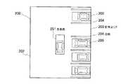
駐車支援装置は、図3に示すように、自車両を駐車エリアに駐車させるために、運転者が駐車エリアの前を徐行している時に運転者によって、操作入力部6の駐車ボタン(図示せず)が押下されたことに従って、表示用画像200を表示部5aに提示する駐車支援動作を開始する。駐車支援装置は、駐車ボタンが押下されたことを認識すると、撮影部2a,2b,2c,2dによって撮影された車両周辺画像データを用いて、画像生成部11によって俯瞰画像を生成して、表示部5aに表示用画像200を表示させる。また、駐車支援装置は、例えば、「駐車支援を開始します。」といった文言を表示部5aに表示させたり、音声出力部5bから音声によって通知しても良い。この時点における表示用画像200には、自車両画像201,駐車前エリア202,駐車エリア203,白線204,他車両205が含まれている。 As shown in FIG. 3, the parking assist device is provided with a parking button (not shown) of the
そして、駐車支援装置は、駐車目標位置を設定し、図4に示すように、駐車エリア203に、情報画像としての駐車目標位置画像206を俯瞰画像に重畳させた表示用画像200を表示させる。このとき、画像生成部11は、運転者の操作に従って駐車目標位置を設定しても良く、障害物検出部3から出力された障害物位置情報に基づいて駐車目標位置を設定しても良く、撮影部2により撮影された画像から白線を認識して駐車目標位置を設定しても良い。 And a parking assistance apparatus sets a parking target position, and as shown in FIG. 4, the
運転者の操作に基づいて駐車目標位置を設定する処理は、移動可能な駐車目標位置画像206を含む俯瞰画像を表示部5aに表示させた状態で、例えば、「ピンク色の枠(駐車目標位置画像206)を止めたい位置に移動、回転させてください。」といった文言を表示部5aに表示させたり、音声出力部5bによって音声通知し、運転者に操作入力部6の操作を促す。そして、画像生成部11は、表示部5aに表示させた駐車目標位置画像206を移動させる操作入力信号を操作入力部6から取得して、駐車目標位置画像206の表示位置を表示用画像200内で変更し、駐車目標位置画像206の位置を設定する操作入力信号を取得したことに応じて、駐車目標位置を決定する。表示部5aに表示させている表示用画像200内の位置を操作入力部6によって決定させる場合、操作入力部6としては、タッチパネルやスクロールキーで構成されていることが望ましい。 The process of setting the parking target position based on the driver's operation is performed, for example, in a state where an overhead image including the movable parking
障害物検出部3から出力された障害物位置情報に基づいて駐車目標位置を設定する処理は、画像生成部11によって、障害物位置情報に基づいて、自車両が駐車可能な奥行き及び幅がある駐車エリア203が存在するかを判断する。駐車可能な駐車エリア203がある場合、画像生成部11は、当該駐車エリア203の中央位置を駐車目標位置として設定する。障害物位置情報に基づいて駐車目標位置を設定する場合、障害物検出部3は、車両の左右前端部に配置された少なくとも2個の超音波センサであることが望ましい。これによって、画像生成部11は、自車両が駐車エリア203の前を通過した時の障害物位置情報を用いて駐車エリア203を判定して、駐車目標位置を設定することができる。 The process of setting the parking target position based on the obstacle position information output from the
白線を認識して駐車目標位置を設定する処理(画像認識手段)は、画像生成部11によって、撮影部2から出力された車両周辺画像を用いて俯瞰画像を生成し、当該俯瞰画像に対してエッジ検出を行って、白線204を検出する。次に画像生成部11は、白線204間の画像領域の色情報と、自車両直近の画像の色情報とを比較して駐車エリア203を検出する。例えば、白線204間に他車両205が存在する画像領域は、自車両直近の画像とは異なる色情報となるが、白線204間に駐車エリア203が存在する画像領域は、自車両直近の画像と同じ色情報となる。又は、画像生成部11は、検出した白線204の間の画像データに対してエッジ検出を行っても良い。このエッジ検出の結果、白線204間に他車両205が含まれる画像領域には多数のエッジが検出され、白線204間に駐車エリア203が含まれる画像領域には検出されるエッジが少ない。 The process (image recognition means) for recognizing the white line and setting the parking target position generates an overhead image using the vehicle peripheral image output from the imaging unit 2 by the
障害物位置情報に基づいて駐車目標位置を設定する処理又は白線を認識して駐車目標位置を設定する処理によって、複数の駐車エリア203が検出された場合には、画像生成部11は、自車両に最も近い駐車目標位置を駐車目標位置画像206として表示させる。また、複数の駐車エリア203が検出された場合には、当該駐車エリア203と自車両との位置関係及び予め記憶しておいた自車両の移動可能範囲に基づいて、自車両が駐車可能な駐車エリア203に駐車目標位置を設定することが望ましい。 When a plurality of
このような画像生成部11は、撮影部2により撮影された車両周辺画像内における駐車目標位置を設定する駐車目標位置設定手段として機能する。 Such an
このように画像生成部11によって駐車目標位置画像206を含む表示用画像200を表示部5aに表示させた場合、駐車支援装置は、駐車目標位置画像206に相当する位置を駐車目標位置として設定するか否かを運転者に確認させる。例えば、「この位置を駐車目標位置として設定してよいですか?」といった文言を表示部5aに表示させたり、音声出力部5bによって音声通知することで、運転者に対して操作入力部6の操作を促す。そして、画像生成部11は、操作入力部6から、現在表示部5aに表示させている駐車目標位置画像206に相当する位置を駐車目標位置として決定する操作入力信号を受信して、駐車目標位置を決定できる。 In this way, when the
次に画像生成部11は、図5に示すように、駐車目標位置に駐車させるために車両を停止させて後退走行を開始させる位置を表す情報画像として駐車初期位置画像207を表示させる。図5に示す表示用画像200は、複数の駐車初期位置画像207a,207b,207c,207d,207eを、車両を後退移動させる前の経由すべき位置として表示させている。また、駐車初期位置画像207a,207b,207c,207d,207eは、自車両画像201と同じ大きさとしている。このような表示用画像200を表示部5aに表示させた状態において、車両周辺画像処理部1は、例えば、「提示する橙色の枠(駐車初期位置画像207)のいずれか一つに自車両を移動させてください。」といった文言を表示部5aに表示させたり、音声出力部5bによって音声通知する。これにより、表示用画像200上において、自車両画像201を駐車初期位置画像207に重畳させるような運転操作を運転者に対して促す。 Next, as shown in FIG. 5, the
この駐車初期位置は、駐車目標位置に対して垂直の関係となり自車両が軌跡208aに示すように後退する駐車初期位置から、タイヤ位置中立点において自車両が軌跡208bに示すように後退することによって駐車目標位置に到達する駐車初期位置までの間で設定される。図5に示す例では、駐車初期位置(207a)と駐車初期位置(207e)との間に、タイヤ切れ角に応じた3個の駐車初期位置を設定して駐車初期位置画像207b,207c,207dを表示させている。このように、画像生成部11は、駐車目標位置と車両の移動可能範囲とに基づいて、車両が当該駐車目標位置に駐車させるために車両を停止させて後退走行を開始させる位置を表す駐車初期位置を演算する駐車初期位置演算手段として機能する。 The initial parking position is perpendicular to the parking target position, and the host vehicle moves backward as indicated by the locus 208b from the initial parking position where the own vehicle moves backward as indicated by the
このように複数の駐車初期位置画像207a,207b,207c,207d,207eを表示した状態において、図6に示すように、自車両が駐車初期位置画像207bに向けて進行した場合、この自車両の移動方向及び移動量は、車両情報取得部4によって取得された車速信号、シフト位置信号、操舵角信号に基づくタイヤ切れ角情報に基づいて、移動演算部12によって演算され、移動量情報として画像生成部11に供給される。また、予測軌跡演算部13は、車両情報取得部4によって取得されたシフト位置信号、操舵角信号に基づくタイヤ切れ角に基づいて、自車両の物理的な移動可能範囲である予想軌跡情報を演算して画像生成部11に供給する。 In a state where a plurality of initial
画像生成部11は、移動量情報に基づいて、自車両の現在位置に対する各駐車初期位置との間の相対的な位置関係を求める。そして、画像生成部11は、自車両と各駐車初期位置との相対的な位置及び予測軌跡演算部13によって供給された予測軌跡情報から、自車両が移動可能な駐車初期位置に相当する駐車初期位置画像207のみを表示用画像200に残し、自車両が移動不可能な駐車初期位置に相当する駐車初期位置画像207を表示用画像200から削除する。 The
図6に示すように、自車両が駐車初期位置画像207bに向けて進行した場合、画像生成部11は、駐車初期位置画像207a,207b,207cを表示用画像200に残し、駐車初期位置画像207d,207eを表示用画像200から削除する。なお、図6に示した表示用画像200には、削除する駐車初期位置画像207d,207eを点線で示したが、実際には表示しない。これにより、駐車支援装置は、自車両の挙動に応じて物理的に移動可能な駐車初期位置画像207のみに絞り込むことができる。 As shown in FIG. 6, when the host vehicle progresses toward the parking
また、自車両の周辺に障害物が存在する場合、当該障害物は、自車両の前端に設けられた超音波センサである障害物検出部3によって検出され、障害物位置情報として画像生成部11に供給される。この場合、画像生成部11は、複数の駐車初期位置と、障害物位置とを比較して、駐車初期位置を表すエリア内に障害物が存在する場合には、当該駐車初期位置には物理的には移動できないことを判定する。このとき、画像生成部11は、図7に示すように、障害物位置情報に基づいて、表示用画像200に、障害物の情報画像としての障害物画像209を重畳させ、自車両が障害物によって物理的に移動できない駐車初期位置画像207aを削除する。 When there is an obstacle around the host vehicle, the obstacle is detected by the
更に自車両を移動させて、自車両が駐車初期位置画像207bに相当する駐車初期位置に到着すると、画像生成部11は、移動演算部12から出力された移動量情報に基づいて、自車両の位置が駐車初期位置を表すエリア内に到達したことを判定する。このとき、画像生成部11は、図8に示すように、自車両画像201が到達した駐車初期位置画像207bを強調した画像207b’とし、当該駐車初期位置画像207bに隣接する駐車初期位置画像207a,207cを削除する。そして、画像生成部11は、駐車初期位置に到達した後に運転者に次の運転操作をさせるために、例えば「駐車初期位置に到達しました。シフトレバーを後退位置(R)に入れてください」といった文言を表示部5aに表示させたり、音声出力部5bによって音声通知することが望ましい。 Further, when the host vehicle is moved and the host vehicle arrives at the initial parking position corresponding to the initial
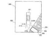
次に、駐車初期位置から自車両を後退走行させて駐車目標位置に案内する場合、画像生成部11は、図9に示すように、予測軌跡演算部13によって演算された駐車初期位置又は自車両画像201から駐車目標位置画像206に繋がる理想軌跡線210R,210Lの情報に従って、表示用画像200に表示させる。この理想軌跡線210R,210Lは、自車両の現在位置と駐車目標位置との相対的な位置関係から、タイヤ切れ角すなわちハンドル操舵角を一定にした状態で後退して駐車目標位置に到達するための軌跡である。また、画像生成部11は、予測軌跡演算部13が演算した現在の操舵角信号に基づく予測軌跡線211R,211Lを俯瞰画像に重畳して表示用画像200に含める。 Next, when the host vehicle is caused to travel backward from the initial parking position and is guided to the target parking position, the
これによって、駐車支援装置は、予測軌跡線211R,211Lを理想軌跡線210R,210Lに重畳させるようなハンドル操作をさせて、自車両を駐車目標位置に導くことができる。このとき、画像生成部11は、例えば「停止した状態でハンドルを回して、ピンク色の線(理想軌跡線210R,210L)に緑色の線(予測軌跡線211R,211L)を合わせてください。その後、ハンドルを固定したままで後退してください。」といった文言を表示部5aに表示させたり、音声出力部5bによって音声通知する。 As a result, the parking assist device can guide the host vehicle to the parking target position by performing a steering operation such that the predicted
次に、理想軌跡線210R,210Lに沿ってハンドル操作をさせて、自車両が駐車目標位置に到達したことを移動演算部12からの移動量情報に基づいて画像生成部11が検出した場合、画像生成部11は、図10に示すように、自車両画像201が到達した駐車目標位置画像206を強調した画像206’を俯瞰画像に重畳させた表示用画像200を表示する。そして、画像生成部11は、例えば「駐車完了です。お疲れ様です。」といった文言を表示部5aに表示させたり、音声出力部5bによって音声通知しても良い。 Next, when the
つぎに、上述したような表示用画像200を運転者に提示する時の駐車支援装置の具体的な処理フローについて図11を参照して説明する。 Next, a specific processing flow of the parking assistance device when the
自車両を駐車する運転操作を支援する駐車支援動作は、運転者によって操作入力部6が操作されることによって駐車支援を開始する操作入力信号を車両周辺画像処理部1が入力したことによって、ステップS1の処理を開始する。 The parking assist operation for assisting the driving operation for parking the host vehicle is performed by the vehicle peripheral
ステップS1においては、画像生成部11によって駐車目標位置を設定して、図4に示すような俯瞰画像に駐車目標位置画像206を重畳させた表示用画像200を表示部5aに表示させる。このとき、画像生成部11は、運転者の入力に基づいて駐車目標位置を設定しても良く、障害物検出部3の障害物位置情報に基づいて駐車目標位置を設定しても良く、画像生成部11が白線を認識することによって駐車目標位置を設定しても良い。 In step S1, the parking target position is set by the
次のステップS2においては、ステップS1にて表示させた駐車目標位置画像206を表示した後に、画像生成部11によって駐車目標位置を決定する操作入力信号を操作入力部6から入力したか否かを判定し、入力した場合にはステップS3に処理を進め、入力していない場合には再度ステップS1にて駐車目標位置の設定を行う。 In the next step S2, after displaying the parking
ステップS3においては、画像生成部11によって、ステップS2にて決定した駐車目標位置に基づいて、複数の駐車初期位置を演算し、図5に示すような俯瞰画像に駐車初期位置画像207a,207b,207c,207d,207eを重畳させた表示用画像200を表示させる。 In step S3, the
次のステップS4においては、画像生成部11によって、移動演算部12によって演算された移動量情報を入力すると共に、障害物検出部3からの障害物位置情報を取得して、車両周辺状況のセンシングを開始する。 In the next step S4, the movement amount information calculated by the
次のステップS5においては、自車両が移動したことに伴い、画像生成部11によって、移動量情報に基づいて自車両位置が変化したこと検知して、俯瞰画像に重畳させる自車両画像201の位置と、駐車目標位置画像206及び駐車初期位置画像207といった情報画像との相対的な位置関係を更新する。 In the next step S5, the position of the
次のステップS6においては、画像生成部11によって、ステップS5にて検出した自車両の位置と駐車初期位置との相対的な位置から、ステップS3にて設定した複数の駐車初期位置のうち、自車両が物理的に移動不可能な駐車初期位置が存在するか否か判定する。図6に示すように自車両が駐車初期位置画像207bに向けて移動している場合、画像生成部11は、物理的に移動不可能な駐車初期位置が存在すると判定して、ステップS7に処理を進める。一方、物理的に移動不可能な駐車初期位置が存在しない場合には、ステップS7をスキップしてステップS8に処理を進める。 In the next step S6, the
ステップS7においては、画像生成部11によって、ステップS6にて物理的に移動不可能な駐車初期位置に相当する駐車初期位置画像207を削除する。例えば図6に示す例では、駐車初期位置画像207d,207eを俯瞰画像から削除した表示用画像200を表示させる。 In step S7, the
次のステップS8においては、画像生成部11によって、障害物検出部3から出力された障害物位置情報と、ステップS3にて設定した駐車初期位置うちでステップS6にて移動不可能な駐車初期位置であることが判断されていない駐車初期位置との位置関係を比較して、駐車初期位置内に障害物が存在するか否かを判定する。図7に示すように駐車初期位置に障害物が存在する場合、ステップS9において、当該駐車初期位置に相当する駐車初期位置画像207aを俯瞰画像から削除した表示用画像200を表示させる。一方、駐車初期位置内に障害物が存在しない場合にはステップS9をスキップしてステップS10に処理を進める。 In the next step S8, the obstacle position information output from the
ステップS10においては、画像生成部11によって、移動演算部12から出力された移動量情報と駐車初期位置とに基づいて、自車両が駐車初期位置に到達したか否かを判定する。自車両が駐車初期位置に到達していない場合にはステップS6〜ステップS9の処理を繰り返し、図8に示すように自車両が駐車初期位置に到達した場合にはステップS11に処理を進める。 In step S10, the
自車両が駐車初期位置に到達した場合、ステップS11において、画像生成部11によって、図8に示すように、当該駐車初期位置に相当する駐車初期位置画像207を強調表示させた画像207b’に変更すると共に、他の駐車初期位置画像207を削除する。 When the host vehicle has reached the initial parking position, in step S11, the
ステップS12においては、車両周辺画像処理部1によって、シフト位置信号によってシフトポジションが後退(R)位置とされたか否かを判定し、後退(R)位置とされた場合にはステップS13に処理を進める。 In step S12, the vehicle periphery
ステップS13においては、画像生成部11によって、予測軌跡演算部13によって演算された理想軌跡線、予測軌跡線の情報に基づいて、図9に示すような理想軌跡線210R,210L及び予測軌跡線211R,211Lを俯瞰画像に重畳させた表示用画像200を表示させる。 In step S13, the
次のステップS14においては、画像生成部11によって、移動演算部12から出力された移動量情報と駐車目標位置との位置関係に基づいて、自車両が駐車目標位置に到達したか否かを判定する。自車両が駐車目標位置に到達していない場合にはステップS13にて理想軌跡線210R,210L、予測軌跡線211R,211Lを描画した表示用画像200を表示し続け、自車両が駐車目標位置に到達した場合には、ステップS15に処理を進める。 In the next step S14, the
ステップS15においては、画像生成部11によって、図10に示すように、当該駐車目標位置に相当する駐車目標位置画像206を強調表示させた画像206’に変更して、処理を終了する。 In step S15, as shown in FIG. 10, the
以上詳細に説明したように、本発明を適用した駐車支援装置によれば、駐車目標位置に対して設定した駐車初期位置のうち車両が移動可能な駐車初期位置のみに絞り込んで駐車初期位置画像207を俯瞰画像に重畳して表示する。したがって、車両の移動方向及び移動量によって変動する車両周囲の状況に応じて、運転者が車両を駐車させる運転操作を支援することができる。 As described above in detail, according to the parking assist device to which the present invention is applied, the initial parking position image 207 is narrowed down to only the initial parking position where the vehicle can move among the initial parking positions set with respect to the parking target position. Is superimposed on the overhead image. Therefore, it is possible to assist the driving operation in which the driver parks the vehicle according to the situation around the vehicle that varies depending on the moving direction and the moving amount of the vehicle.
また、この駐車支援装置によれば、障害物が存在する場合には、当該障害物の存在によって車両が物理的に移動不可能な駐車初期位置の駐車初期位置画像207を削除した表示用画像200を表示させるので、障害物によって進入できない位置に駐車初期位置画像207を提示することを回避できる。 Further, according to this parking assist apparatus, when there is an obstacle, the
更に、この駐車支援装置によれば、運転者が駐車目標位置を選択する操作に従って駐車目標位置を設定するので、運転者が希望する駐車目標位置を設定でき、当該駐車目標位置に到達するために車両が移動可能な駐車初期位置を設定できる。 Furthermore, according to this parking assist device, the driver sets the parking target position in accordance with the operation of selecting the parking target position, so that the driver can set the desired parking target position and reach the parking target position. The initial parking position where the vehicle can move can be set.
更にまた、この駐車支援装置によれば、他車両を含む障害物がないスペースを駐車目標位置に設定でき、障害物がないスペースの近傍に車両を通過させるだけで、駐車目標位置を設定することができる。そして、当該駐車目標位置に到達するために車両が移動可能な駐車初期位置を設定できる。 Furthermore, according to this parking assist apparatus, a space without an obstacle including other vehicles can be set as a parking target position, and the parking target position can be set only by passing the vehicle in the vicinity of the space without an obstacle. Can do. And the parking initial position which a vehicle can move in order to reach the said parking target position can be set.
更にまた、この駐車支援装置によれば、白線間における画像情報に基づいて駐車目標位置を設定するので、白線が描かれているスペースの近傍に車両を通過させるだけで、駐車目標位置を設定することができる。そして、当該駐車目標位置に到達するために車両が移動可能な駐車初期位置を設定できる。 Furthermore, according to this parking assist device, the parking target position is set based on the image information between the white lines, so the parking target position is set only by passing the vehicle in the vicinity of the space where the white line is drawn. be able to. And the parking initial position which a vehicle can move in order to reach the said parking target position can be set.
このように駐車支援装置は、運転者に対して、自由度の高い駐車初期位置を提示することができる。 Thus, the parking assistance device can present the initial parking position with a high degree of freedom to the driver.
更にまた、この駐車支援装置によれば、車両が駐車初期位置に到着した場合には駐車初期位置画像207を削除して、理想軌跡線210R,210L及び予測軌跡線211R,211Lを俯瞰画像に重畳して表示させるので、運転者に対して、車両を駐車初期位置に向けて走行させる運転操作から、車両を駐車目的位置に向けて走行させる運転操作に移行したことを通知できる。 Furthermore, according to this parking assistance apparatus, when the vehicle arrives at the initial parking position, the initial parking position image 207 is deleted, and the
つぎに、本発明を適用した駐車支援装置の第2実施形態について説明する。なお、上述の実施形態と同様の部分については同一符号を付することによりその詳細な説明を省略する。 Below, 2nd Embodiment of the parking assistance apparatus to which this invention is applied is described. Note that parts similar to those in the above-described embodiment are denoted by the same reference numerals, and detailed description thereof is omitted.
上述した第1実施形態に示した駐車支援装置は、図5を参照して説明したように、駐車初期位置を、駐車目標位置に対して垂直の関係となる駐車初期位置から、タイヤ位置中立点において自車両が後退することによって駐車目標位置に到達する駐車初期位置までの間で、駐車初期位置画像207を表示させている。第1実施形態に係る駐車初期位置は、図5に示す例においては、自車両画像201と同じ大きさの5個の四角状の駐車初期位置画像207a,207b,207c,207d,207eを表示させていた。 As described with reference to FIG. 5, the parking assist device shown in the first embodiment described above sets the initial parking position from the initial parking position that is perpendicular to the parking target position, to the tire position neutral point. The initial parking position image 207 is displayed until the initial parking position that reaches the parking target position when the host vehicle moves backward in FIG. In the example shown in FIG. 5, the initial parking position according to the first embodiment displays five square-shaped initial
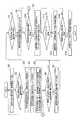
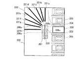
これに対し、第2実施形態に係る駐車支援装置は、図12に示すように、放射状にライン形状の複数の駐車初期位置画像221a,221b,221c,221d,221e,221f,221g、221hを俯瞰画像に重畳させた表示用画像200を表示させる。このライン状の駐車初期位置画像221a,221b,221c,221d,221e,221f,221g、221hのうち、駐車初期位置画像221aは、上述の駐車初期位置画像207aの中心位置に相当し、駐車初期位置画像221hは、上述の駐車初期位置画像207eの中心位置に相当する。したがって、駐車初期位置画像221は、上述した駐車初期位置画像207と同様に、駐車目標位置に対して垂直の関係となる駐車初期位置から、タイヤ位置中立点において自車両が後退することによって駐車目標位置に到達する駐車初期位置までを表している。 On the other hand, as shown in FIG. 12, the parking assistance apparatus according to the second embodiment has a bird's-eye view of a plurality of radially initial
また、第2実施形態に係る駐車支援装置は、自車両画像201の中心軸に、ライン状の中心軸画像220を俯瞰画像に重畳させる。なお、この中心軸画像220は、自車両画像201上に重畳させている例を示しているが、自車両画像201を表示させなくても良い。 Moreover, the parking assistance apparatus according to the second embodiment superimposes the line-shaped
このように駐車初期位置画像221及び中心軸画像220を俯瞰画像に重畳させた表示用画像200を表示部5aに表示させている状態において、駐車支援装置は、中心軸画像220を駐車初期位置画像221に重なるような運転操作を促すために、例えば、「提示する橙色のライン(駐車初期位置画像221)と自車両の中心軸(中心軸画像220)を重ねるよう移動させてください。」といった文言を表示部5aに表示させたり、音声出力部5bによって音声通知する。 Thus, in the state where the
駐車初期位置画像221を表示させている状態において、自車両が走行すると、当該自車両の移動量情報は、移動演算部12から画像生成部11に出力される。これにより、例えば図13に示すように、自車両画像201及び中心軸画像220と共に、駐車初期位置画像221に近づくと、俯瞰画像の表示範囲が変化する。これに応じ、画像生成部11は、駐車初期位置画像221の長さも長く変化させる必要がある。すなわち、駐車初期位置画像221が伸びている方向に俯瞰画像の表示エリアが広がれば、駐車初期位置画像221も伸ばす。 When the host vehicle travels in a state where the parking
また、図13に示すように、車両が駐車初期位置画像221cに相当する駐車初期位置に移動すると、画像生成部11は、現在の自車両と各駐車初期位置との位置関係から、自車両が移動不可能な駐車初期位置を認識する。また、画像生成部11は、障害物検出部3から出力された障害物位置情報に基づいて、障害物の存在によって車両が移動不可能な駐車初期位置を認識する。このような車両が移動不可能な駐車初期位置に相当する駐車初期位置画像221a,221f,221g、221hは、図13に示すように、削除されることとなり、車両が移動可能な駐車初期位置画像221b,221c,221d,221eのみを表示させる。 Further, as shown in FIG. 13, when the vehicle moves to the initial parking position corresponding to the initial
更に車両が移動し、図14に示すように、ある駐車初期位置画像221に中心軸画像220が重畳する状態となると、当該駐車初期位置画像221以外の駐車初期位置画像221を削除する。 When the vehicle further moves and the
以上のように、第2実施形態に係る駐車支援装置によれば、車両が移動可能な駐車初期位置を複数に亘って表示して、車両の移動可能な範囲及び障害物などの状況に応じて自由度の高い駐車初期位置を運転者に提示することができる。 As described above, according to the parking assistance device according to the second embodiment, the initial parking position where the vehicle can move is displayed over a plurality of times, depending on the range of the vehicle and the situation such as obstacles. A parking initial position with a high degree of freedom can be presented to the driver.
つぎに、本発明を適用した駐車支援装置の第3実施形態について説明する。なお、上述の実施形態と同様の部分については同一符号を付することによりその詳細な説明を省略する。 Below, 3rd Embodiment of the parking assistance apparatus to which this invention is applied is described. Note that parts similar to those in the above-described embodiment are denoted by the same reference numerals, and detailed description thereof is omitted.
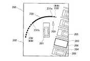
第3実施形態に係る駐車支援装置は、図15に示すように、単一の領域を表す駐車初期位置画像230を表示することを特徴とする。この駐車初期位置画像230は、所定幅の円弧状の曲線によって駐車初期位置を表している。この駐車初期位置画像230の端部231aは、上述した図5に示した駐車初期位置画像207aの端部位置を示しており、駐車初期位置画像230の端部231bは、上述した図5に示した駐車初期位置画像207eの端部を示している。したがって、駐車初期位置画像230は、上述した駐車初期位置画像207と同様に、駐車目標位置に対して垂直の関係となる駐車初期位置から、タイヤ位置中立点において自車両が後退することによって駐車目標位置に到達する駐車初期位置までを表している。 As shown in FIG. 15, the parking assistance apparatus according to the third embodiment displays a parking
このように駐車初期位置画像230を俯瞰画像に重畳させた表示用画像200を表示部5aに表示させている状態において、駐車支援装置は、自車両画像201の先端を駐車初期位置画像230に重なるような運転操作を促すために、例えば、「提示する橙色の領域(駐車初期位置画像230)に自車両の先端を入れるように移動させてください。」といった文言を表示部5aに表示させたり、音声出力部5bによって音声通知する。 Thus, in a state where the
駐車初期位置画像230を表示させている状態において、自車両が走行すると、当該自車両の移動量情報は、移動演算部12から画像生成部11に出力される。これにより、例えば図16に示すように、自車両画像201が、駐車初期位置画像230に近づくと、画像生成部11は、現在の自車両と駐車初期位置との位置関係から、自車両が移動不可能な駐車初期位置を認識する。また、画像生成部11は、障害物検出部3から出力された障害物位置情報に基づいて、障害物の存在によって車両が移動不可能な駐車初期位置を認識する。このような車両が移動不可能な駐車初期位置に相当する駐車初期位置画像230’は、図16に示すように、移動不可能な範囲に相当する分だけ削除されることとなり、車両が移動可能な範囲の駐車初期位置画像230のみを表示させる。 When the host vehicle travels in a state where the parking
更に車両が移動し、図17に示すように、ある範囲の駐車初期位置画像230に自車両画像201が重畳する状態となると、当該駐車初期位置画像230以外の駐車初期位置画像230を削除する。 When the vehicle further moves and the
以上のように、第3実施形態に係る駐車支援装置によれば、車両が移動可能な駐車初期位置を領域として表示して、車両の移動可能な範囲及び障害物などの状況に応じて自由度の高い駐車初期位置を運転者に提示することができる。 As described above, according to the parking assistance device according to the third embodiment, the initial parking position where the vehicle can move is displayed as a region, and the degree of freedom is determined according to the range of the vehicle and the situation such as obstacles. A high initial parking position can be presented to the driver.
なお、上述の実施の形態は本発明の一例である。このため、本発明は、上述の実施形態に限定されることはなく、この実施の形態以外であっても、本発明に係る技術的思想を逸脱しない範囲であれば、設計等に応じて種々の変更が可能であることは勿論である。 The above-described embodiment is an example of the present invention. For this reason, the present invention is not limited to the above-described embodiment, and various modifications can be made depending on the design and the like as long as the technical idea according to the present invention is not deviated from this embodiment. Of course, it is possible to change.
1 車両周辺画像処理部
2a,2b,2c,2d 撮影部(撮影手段)
3 障害物検出部(障害物検出手段)
4 車両情報取得部
5 情報提示部
5a 表示部
5b 音声出力部
6 操作入力部(操作手段)
11 画像生成部(駐車目標位置設定手段、駐車初期位置演算手段、画像生成手段、画像認識手段)
12 移動演算部(移動検出手段)
13 予測軌跡演算部
101 俯瞰画像
102a〜102d 車両周辺画像
103 ライン
104a〜104d 部分画像
105 自車両マーク
200 表示用画像
201 自車両画像
202 駐車前エリア
203 駐車エリア
204 白線
205 他車両
206 駐車目標位置画像
207 駐車初期位置画像
208a,208b 軌跡
209 障害物画像
210R,210L 理想軌跡線
211R,211L 予測軌跡線
220 中心軸画像
221 駐車初期位置画像
230 駐車初期位置画像
231a,231b 端部1 Vehicle periphery
3 Obstacle detection unit (obstacle detection means)
4 vehicle
11 Image generation unit (parking target position setting means, parking initial position calculation means, image generation means, image recognition means)
12 Movement calculation part (movement detection means)
DESCRIPTION OF
Claims (10)
Translated fromJapanese前記撮影手段により撮影された車両周辺画像内における駐車目標位置を設定する駐車目標位置設定手段と、
前記駐車目標位置設定手段により設定された駐車目標位置と車両の移動可能範囲とに基づいて、車両が当該駐車目標位置に駐車させるために車両を停止させて後退走行を開始させる位置を表す駐車初期位置を演算する駐車初期位置演算手段と、
車両の移動方向及び移動量を検出する移動検出手段と、
車両が前記駐車初期位置演算手段により演算された駐車初期位置に向けて進行したことに応じて、前記移動検出手段により検出された移動方向及び移動量に基づいて、前記駐車初期位置演算手段により演算された駐車初期位置のうち車両が移動可能な駐車初期位置を表す情報画像のみを前記車両周辺画像に重畳させ、車両が移動不可能な駐車初期位置を表す情報画像を前記車両周辺画像から削除する画像生成手段と
を備えることを特徴とする駐車支援装置。Photographing means for photographing the periphery of the vehicle;
A parking target position setting means for setting a parking target position in a vehicle peripheral image photographed by the photographing means;
Based on the parking target position set by the parking target position setting means and the movable range of the vehicle, the initial stage of parking represents a position where the vehicle stops and starts reverse traveling in order to park at the parking target position. A parking initial position calculating means for calculating a position;
A movement detecting means for detecting a moving direction and a moving amount of the vehicle;
Calculated by the parking initial position calculating means based on the moving direction and moving amount detected by the movement detecting meansin response to the vehicle traveling toward the parking initial position calculated by the parking initial position calculating means. Only the information image representing the parking initial position where the vehicle can move among the set initial parking positions is superimposed on the vehicle surrounding image,and the information image representing the parking initial position where the vehicle cannot move is deleted from the vehicle surrounding image. A parking assistance device comprising: an image generation means.
前記撮影手段により撮影された車両周辺画像内における駐車目標位置を設定する駐車目標位置設定手段と、
前記駐車目標位置設定手段により設定された駐車目標位置と車両の移動可能範囲とに基づいて、車両が当該駐車目標位置に駐車させるために車両を停止させて後退走行を開始させる位置を表す駐車初期位置を演算する駐車初期位置演算手段と、
車両の移動方向及び移動量を検出する移動検出手段と、
車両が前記駐車初期位置演算手段により演算された駐車初期位置に向けて進行したことに応じて、前記移動検出手段により検出された移動方向及び移動量に基づいて、前記駐車初期位置演算手段により演算された駐車初期位置のうち、車両が移動可能な駐車初期位置を表す情報画像のみを前記車両周辺画像に表示するように車両が移動不可能な駐車初期位置を表す情報画像を更新する画像生成手段と
を備えることを特徴とする駐車支援装置。Photographing means for photographing the periphery of the vehicle;
A parking target position setting means for setting a parking target position in a vehicle peripheral image photographed by the photographing means;
Based on the parking target position set by the parking target position setting means and the movable range of the vehicle, the initial stage of parking represents a position where the vehicle stops and starts reverse traveling in order to park at the parking target position. A parking initial position calculating means for calculating a position;
A movement detecting means for detecting a moving direction and a moving amount of the vehicle;
Calculated by the parking initial position calculating means based on the moving direction and moving amount detected by the movement detecting meansin response to the vehicle traveling toward the parking initial position calculated by the parking initial position calculating means. Image generating meansfor updating an information image representing an initial parking position where the vehicle cannot move so that only an information image representing an initial parking positionwhere the vehicle can move is displayed on the vehicle peripheral imageamong the parked initial positions. A parking support device comprising:
前記画像生成手段は、前記障害物検出手段により検出された障害物の位置に基づいて、前記駐車初期位置演算手段により演算された駐車初期位置のうち当該障害物によって移動ができない駐車初期位置を表す情報画像を削除することを特徴とする請求項1乃至請求項3の何れか一項に記載の駐車支援装置。An obstacle detection means for detecting the position of an obstacle present around the vehicle;
The image generation means represents a parking initial position that cannot be moved by the obstacle among the initial parking positions calculated by the parking initial position calculation means based on the position of the obstacle detected by the obstacle detection means. The parking support device according toany one of claims 1 to 3, wherein the information image is deleted.
前記駐車目標位置設定手段は、前記障害物検出手段により障害物が検出されていない領域を駐車目標位置に設定することを特徴とする請求項1乃至請求項3の何れか一項に記載の駐車支援装置。An obstacle detection means for detecting the position of an obstacle present around the vehicle;
The said parking target position setting means sets the area | region where the obstruction is not detected by the said obstacle detection means to a parking target position, The parking as described inany one of Claim 1thru | or 3 characterized by the above-mentioned. Support device.
前記駐車目標位置設定手段は、前記画像認識手段により認識された白線間の画像情報に基づいて、駐車目標位置を設定することを特徴とする請求項1乃至請求項3の何れか一項に記載の駐車支援装置。An image recognition means for recognizing a white line included in the vehicle periphery image photographed by the photographing means;
The said parking target position setting means sets a parking target position based on the image information between the white lines recognized by the said image recognition means, The Claim 1thru | or 3 characterized by the above-mentioned. Parking assistance device.
前記移動検出手段により検出された車両の移動方向及び移動量に基づいて車両の位置が前記駐車初期位置に到達したと判定した場合には、前記駐車初期位置を表す情報画像を削除し、
車両が到達した駐車初期位置から前記駐車目標位置までの車両の理想軌跡線及び車両の操舵角に基づく予測軌跡線を車両周辺画像に重畳させること
を特徴とする請求項1乃至請求項7の何れか一項に記載の駐車支援装置。The image generating means includes
When it is determined that the position of the vehicle has reached the parking initial position based on the moving direction and amount of movement of the vehicle detected by the movement detecting means, the information image representing the parking initial position is deleted,
Any from the parking initial position where the vehicle reaches the claims 1 to7, characterized in that to superimpose the predicted locus line based on the steering angle of the ideal track line and the vehicle of the vehicle to the parking target position on the vehicle periphery image The parking assistance device according to claim 1.
前記駐車目標位置及び前記駐車初期位置を前記撮影した車両周辺画像に重畳させて表示し、
車両が前記駐車初期位置に向けて進行したことに応じて、検出された車両の移動方向及び移動量に基づいて、前記駐車初期位置のうち車両が移動可能な駐車初期位置を表す情報画像のみを前記車両周辺画像に重畳させ、車両が移動不可能な駐車初期位置を表す情報画像を前記車両周辺画像から削除するように表示させている画像を変更すること
を特徴とする駐車支援方法。Set the parking target position in the captured vehicle periphery image, and stop the vehicle based on the set parking target position and the movable range of the vehicle, and stop the vehicle to park at the parking target position. Calculate the parking initial position indicating the position to start
The parking target position and the parking initial position are displayed superimposed on the captured vehicle peripheral image,
Depending on the vehicle has proceeded toward the parking initial position, based on the movement direction and the movement amount of the detected vehicle,the vehicle of the parking initial position only the information image representing the parking initial position movable A parking support method, comprising: superimposing theimage on the vehicle periphery image and changing an image displayed so asto delete the information image representing an initial parking position where the vehicle cannot move from the vehicle periphery image .
前記駐車目標位置及び前記駐車初期位置を前記撮影した車両周辺画像に重畳させて表示し、
車両が前記駐車初期位置に向けて進行したことに応じて、検出された車両の移動方向及び移動量に基づいて、前記駐車初期位置のうち車両が移動可能な駐車初期位置を表す情報画像のみを前記車両周辺画像に表示するように車両が移動不可能な駐車初期位置を表す情報画像を更新するように表示させている画像を変更すること
を特徴とする駐車支援方法。Set the parking target position in the captured vehicle periphery image, and stop the vehicle based on the set parking target position and the movable range of the vehicle, and stop the vehicle to park at the parking target position. Calculate the parking initial position indicating the position to start
The parking target position and the parking initial position are displayed superimposed on the captured vehicle peripheral image,
Depending on the vehicle has proceeded toward the parking initial position, based on the movement direction and the movement amount of the detected vehicle,the vehicle of the parking initial position only the information image representing the parking initial position movable The parking assistance method characterized by changing the image displayed so that theinformation image showing the parking initial position which a vehicle cannot move is updated so thatit may display on the said vehicle periphery image.
Priority Applications (8)
| Application Number | Priority Date | Filing Date | Title |
|---|---|---|---|
| JP2007257986AJP5088074B2 (en) | 2007-10-01 | 2007-10-01 | Parking support apparatus and method |
| EP10015986AEP2301823B1 (en) | 2007-10-01 | 2008-09-22 | Parking assistant and parking assisting method |
| AT08836709TATE521522T1 (en) | 2007-10-01 | 2008-09-22 | PARKING ASSISTANCE AND PARKING ASSISTANCE PROCEDURES |
| EP10015982AEP2298627B1 (en) | 2007-10-01 | 2008-09-22 | Parking assistant and parking assisting method |
| CN200880109874.3ACN101815642B (en) | 2007-10-01 | 2008-09-22 | Parking assistant and parking assisting method |
| US12/680,400US8855850B2 (en) | 2007-10-01 | 2008-09-22 | Parking assistant and parking assisting method |
| EP08836709AEP2212182B1 (en) | 2007-10-01 | 2008-09-22 | Parking assistant and parking assisting method |
| PCT/JP2008/002615WO2009044513A1 (en) | 2007-10-01 | 2008-09-22 | Parking assistant and parking assisting method |
Applications Claiming Priority (1)
| Application Number | Priority Date | Filing Date | Title |
|---|---|---|---|
| JP2007257986AJP5088074B2 (en) | 2007-10-01 | 2007-10-01 | Parking support apparatus and method |
Publications (2)
| Publication Number | Publication Date |
|---|---|
| JP2009083735A JP2009083735A (en) | 2009-04-23 |
| JP5088074B2true JP5088074B2 (en) | 2012-12-05 |
Family
ID=40191335
Family Applications (1)
| Application Number | Title | Priority Date | Filing Date |
|---|---|---|---|
| JP2007257986AActiveJP5088074B2 (en) | 2007-10-01 | 2007-10-01 | Parking support apparatus and method |
Country Status (6)
| Country | Link |
|---|---|
| US (1) | US8855850B2 (en) |
| EP (3) | EP2212182B1 (en) |
| JP (1) | JP5088074B2 (en) |
| CN (1) | CN101815642B (en) |
| AT (1) | ATE521522T1 (en) |
| WO (1) | WO2009044513A1 (en) |
Cited By (1)
| Publication number | Priority date | Publication date | Assignee | Title |
|---|---|---|---|---|
| KR101877570B1 (en) | 2012-04-04 | 2018-07-11 | 현대자동차주식회사 | Apparatus for setting parking position based on around view image and method thereof |
Families Citing this family (42)
| Publication number | Priority date | Publication date | Assignee | Title |
|---|---|---|---|---|
| JP4882302B2 (en)* | 2005-07-28 | 2012-02-22 | 株式会社アドヴィックス | Parking assistance control device and parking assistance control system |
| JP4900232B2 (en)* | 2007-12-26 | 2012-03-21 | 日産自動車株式会社 | Vehicle parking assist device and video display method |
| JP5376223B2 (en)* | 2009-05-18 | 2013-12-25 | アイシン精機株式会社 | Driving assistance device |
| JP5321267B2 (en)* | 2009-06-16 | 2013-10-23 | 日産自動車株式会社 | Vehicular image display device and overhead image display method |
| EP2340980B1 (en)* | 2009-12-30 | 2012-05-30 | Magneti Marelli S.p.A. | Parking assistant system |
| CN201646714U (en) | 2010-01-26 | 2010-11-24 | 德尔福技术有限公司 | Parking guiding system |
| EP2360054B1 (en)* | 2010-01-26 | 2015-03-18 | Delphi Technologies, Inc. | A parking guidance system |
| JP5501452B2 (en)* | 2010-05-19 | 2014-05-21 | 三菱電機株式会社 | Vehicle rear monitoring device |
| JP5099195B2 (en)* | 2010-09-24 | 2012-12-12 | 株式会社デンソー | Reverse parking assist device for vehicle and program for reverse parking assist device |
| DE102011003881A1 (en)* | 2011-02-09 | 2012-08-09 | Robert Bosch Gmbh | Method for assisting a driver of a motor vehicle |
| US20120249342A1 (en)* | 2011-03-31 | 2012-10-04 | Koehrsen Craig L | Machine display system |
| KR20130036431A (en)* | 2011-10-04 | 2013-04-12 | 주식회사 만도 | Method, apparatus, and system for parking control |
| KR101327736B1 (en)* | 2011-12-23 | 2013-11-11 | 현대자동차주식회사 | AVM Top View Based Parking Support System |
| JP2013154730A (en)* | 2012-01-30 | 2013-08-15 | Fujitsu Ten Ltd | Apparatus and method for processing image, and parking support system |
| CN103661270A (en)* | 2012-09-21 | 2014-03-26 | 北京酷信通科技有限公司 | Car panoramic intelligent safeguard system |
| US20140118549A1 (en)* | 2012-10-31 | 2014-05-01 | Nissan North America, Inc. | Automated vehicle periphery monitoring apparatus and image displaying method |
| WO2014073193A1 (en)* | 2012-11-06 | 2014-05-15 | パナソニック株式会社 | Parking assist device |
| JP6328369B2 (en)* | 2012-11-27 | 2018-05-23 | クラリオン株式会社 | In-vehicle control device |
| CN104085395A (en)* | 2013-04-01 | 2014-10-08 | 德尔福电子(苏州)有限公司 | Auxiliary parking method based on aerial view system |
| US10773642B2 (en)* | 2013-11-06 | 2020-09-15 | Frazier Cunningham, III | Vehicle driver nudge system |
| DE102014110851A1 (en)* | 2014-07-31 | 2016-02-04 | Valeo Schalter Und Sensoren Gmbh | A method for assisting a driver of a motor vehicle when parking, driver assistance system and motor vehicle |
| DE102014111128A1 (en)* | 2014-08-05 | 2016-02-11 | Valeo Schalter Und Sensoren Gmbh | Providing driving instructions during a parking maneuver |
| CN104900112B (en)* | 2015-06-17 | 2017-08-08 | 重庆大学 | Vehicle drive intelligent teaching auxiliary direction method and system |
| DE102015211754A1 (en)* | 2015-06-24 | 2016-12-29 | Bayerische Motoren Werke Aktiengesellschaft | Parking assistance system for the automated carrying out of a parking maneuver in a transverse parking space with detection of a bottom parking space bounding the rear parking space obstacle |
| CN105160929A (en)* | 2015-07-30 | 2015-12-16 | 小米科技有限责任公司 | Parking spot query method and parking spot query device |
| KR101795151B1 (en)* | 2015-10-05 | 2017-12-01 | 현대자동차주식회사 | Parking guidance apparatus and method for vehicle |
| JP6594736B2 (en)* | 2015-10-27 | 2019-10-23 | クラリオン株式会社 | Parking assistance device |
| JP6509361B2 (en)* | 2015-10-30 | 2019-05-08 | 三菱電機株式会社 | Parking support device and parking support method |
| JP6931818B2 (en)* | 2015-12-08 | 2021-09-08 | パナソニックIpマネジメント株式会社 | Parking support device, parking support method and parking support program |
| US10683035B2 (en) | 2015-12-08 | 2020-06-16 | Panasonic Intellectual Property Management Co., Ltd. | Parking assistance device, parking assistance method, and non-transitory computer readable medium |
| JP6545108B2 (en)* | 2016-01-14 | 2019-07-17 | アルパイン株式会社 | Parking assistance apparatus and parking assistance method |
| JP6656359B2 (en)* | 2016-04-15 | 2020-03-04 | 三菱電機株式会社 | Parking assist display control device and parking assist display control method |
| WO2017179205A1 (en)* | 2016-04-15 | 2017-10-19 | 三菱電機株式会社 | Display control device for parking assistance, and display control method for parking assistance |
| JP6743593B2 (en)* | 2016-08-31 | 2020-08-19 | アイシン精機株式会社 | Parking assistance device |
| KR102395278B1 (en)* | 2016-12-02 | 2022-05-09 | 현대자동차주식회사 | Apparatus for regenerating parking path, system having the same and method thereof |
| CN108622082B (en)* | 2017-03-17 | 2021-04-16 | 厦门歌乐电子企业有限公司 | Parking auxiliary control method and device |
| DE102017113799A1 (en)* | 2017-06-22 | 2018-12-27 | Connaught Electronics Ltd. | Driving assistance for a one-lane road |
| CN108569280B (en)* | 2017-12-15 | 2020-03-24 | 上海蔚来汽车有限公司 | Method and device for automatic parking, intelligent automobile and computer storage medium |
| DE102019204656A1 (en)* | 2019-04-02 | 2020-10-08 | Conti Temic Microelectronic Gmbh | Parking assistance system |
| JP7455482B2 (en)* | 2020-09-18 | 2024-03-26 | アルプスアルパイン株式会社 | vehicle support equipment |
| DE102021200188B3 (en)* | 2021-01-11 | 2022-06-02 | Volkswagen Aktiengesellschaft | Method for supporting a driver of a motor vehicle during a parking maneuver and motor vehicle |
| US11999342B2 (en) | 2021-05-26 | 2024-06-04 | Panasonic Automotive Systems Co., Ltd. | Display control device, parking assist apparatus and display control method |
Family Cites Families (45)
| Publication number | Priority date | Publication date | Assignee | Title |
|---|---|---|---|---|
| US2955507A (en)* | 1959-02-16 | 1960-10-11 | Leitz Ernst Gmbh | Focussing plate for optical instruments |
| JPH11208420A (en) | 1998-01-27 | 1999-08-03 | Nissan Motor Co Ltd | Parking guidance device and automatic parking device |
| US6285317B1 (en)* | 1998-05-01 | 2001-09-04 | Lucent Technologies Inc. | Navigation system with three-dimensional display |
| EP2410742A1 (en) | 1999-04-16 | 2012-01-25 | Panasonic Corporation | Image processing apparatus and monitoring system |
| US7366595B1 (en)* | 1999-06-25 | 2008-04-29 | Seiko Epson Corporation | Vehicle drive assist system |
| JP4312883B2 (en) | 1999-06-29 | 2009-08-12 | 富士通テン株式会社 | Vehicle parking assist device |
| JP3575364B2 (en) | 1999-12-28 | 2004-10-13 | 株式会社豊田自動織機 | Steering support device |
| DE10117650A1 (en)* | 2001-04-09 | 2002-10-10 | Daimler Chrysler Ag | Bringing vehicle to target position, involves outputting control commands to drive train, braking system and/or steering so vehicle can be steered to target position independently of driver |
| JP4156214B2 (en)* | 2001-06-13 | 2008-09-24 | 株式会社デンソー | Vehicle periphery image processing apparatus and recording medium |
| JP2003104149A (en) | 2001-09-27 | 2003-04-09 | Equos Research Co Ltd | Parking assistance device |
| JP2003115100A (en) | 2001-10-03 | 2003-04-18 | Denso Corp | Vehicle peripheral image processor |
| US6683539B2 (en)* | 2001-12-27 | 2004-01-27 | Koninklijke Philips Electronics N.V. | Computer vision based parking assistant |
| JP3949007B2 (en)* | 2002-05-30 | 2007-07-25 | アルパイン株式会社 | Navigation device |
| US20040003351A1 (en)* | 2002-06-28 | 2004-01-01 | Microsoft Corporation | Navigating a resource browser session |
| JP4427953B2 (en)* | 2003-01-29 | 2010-03-10 | 株式会社豊田自動織機 | Parking assistance device |
| JP2004235986A (en) | 2003-01-30 | 2004-08-19 | Matsushita Electric Ind Co Ltd | Monitoring system |
| JP3927512B2 (en)* | 2003-03-27 | 2007-06-13 | トヨタ自動車株式会社 | Parking assistance device |
| JP2004306814A (en)* | 2003-04-08 | 2004-11-04 | Auto Network Gijutsu Kenkyusho:Kk | Parking assistance device |
| JP3809431B2 (en)* | 2003-08-28 | 2006-08-16 | トヨタ自動車株式会社 | Parking assistance device |
| DE10339645A1 (en)* | 2003-08-28 | 2005-04-14 | Robert Bosch Gmbh | Method and device for determining the size and position of a parking space |
| JP4244804B2 (en)* | 2003-12-25 | 2009-03-25 | トヨタ自動車株式会社 | Integrated control system for vehicles |
| DE102004001428A1 (en)* | 2004-01-09 | 2005-08-04 | Robert Bosch Gmbh | Method for driver assistance systems for improving the parking starting position |
| JP2005239048A (en) | 2004-02-27 | 2005-09-08 | Denso Corp | Parking assistance system |
| DE102004027640A1 (en)* | 2004-06-05 | 2006-06-08 | Robert Bosch Gmbh | Method and device for assisted parking of a motor vehicle |
| JP4461920B2 (en)* | 2004-06-23 | 2010-05-12 | 株式会社デンソー | Parking assistance device |
| DE102004047481A1 (en)* | 2004-09-30 | 2006-04-13 | Robert Bosch Gmbh | Method for displaying a vehicle driving space |
| JP2006123606A (en)* | 2004-10-26 | 2006-05-18 | Toyota Motor Corp | Parking assistance device |
| JP4449701B2 (en) | 2004-10-28 | 2010-04-14 | 株式会社デンソー | Parking assistance system |
| JP4573242B2 (en)* | 2004-11-09 | 2010-11-04 | アルパイン株式会社 | Driving assistance device |
| JP4179285B2 (en) | 2005-01-12 | 2008-11-12 | トヨタ自動車株式会社 | Parking assistance device |
| US20060235590A1 (en)* | 2005-02-11 | 2006-10-19 | Farhad Bolourchi | Parking assist utilizing steering system |
| JP2006290051A (en)* | 2005-04-06 | 2006-10-26 | Nissan Motor Co Ltd | Parking assistance device and parking assistance method |
| JP4956915B2 (en)* | 2005-05-20 | 2012-06-20 | 日産自動車株式会社 | Video display device and video display method |
| JP2006341641A (en) | 2005-06-07 | 2006-12-21 | Nissan Motor Co Ltd | Video display device and video display method |
| JP2007030700A (en)* | 2005-07-27 | 2007-02-08 | Aisin Seiki Co Ltd | Parking assistance device |
| JP2007088577A (en) | 2005-09-20 | 2007-04-05 | Denso Corp | Vehicle surrounding image processing system |
| JP4414959B2 (en) | 2005-11-16 | 2010-02-17 | アイシン精機株式会社 | Parking assistance device |
| TW200722311A (en)* | 2005-12-06 | 2007-06-16 | Kinpo Elect Inc | Parking guidance apparatus and method |
| JP2007168560A (en) | 2005-12-21 | 2007-07-05 | Denso Corp | Parking support apparatus |
| JP2007183877A (en) | 2006-01-10 | 2007-07-19 | Nissan Motor Co Ltd | Vehicle driving support apparatus and overhead video display method |
| JP4910425B2 (en) | 2006-03-01 | 2012-04-04 | 日産自動車株式会社 | Parking assistance device and parking assistance method |
| JP4963368B2 (en) | 2006-03-23 | 2012-06-27 | 株式会社Ihi | Apparatus and method for measuring profile of electron beam and laser beam |
| JP5309442B2 (en)* | 2006-05-29 | 2013-10-09 | アイシン・エィ・ダブリュ株式会社 | Parking support method and parking support device |
| US7518545B2 (en)* | 2006-10-26 | 2009-04-14 | Infineon Technologies Ag | Driver assistance system |
| KR100974704B1 (en)* | 2007-04-30 | 2010-08-06 | 현대자동차주식회사 | Parking guidance method of car |
- 2007
- 2007-10-01JPJP2007257986Apatent/JP5088074B2/enactiveActive
- 2008
- 2008-09-22EPEP08836709Apatent/EP2212182B1/enactiveActive
- 2008-09-22WOPCT/JP2008/002615patent/WO2009044513A1/enactiveApplication Filing
- 2008-09-22EPEP10015986Apatent/EP2301823B1/enactiveActive
- 2008-09-22ATAT08836709Tpatent/ATE521522T1/ennot_activeIP Right Cessation
- 2008-09-22CNCN200880109874.3Apatent/CN101815642B/enactiveActive
- 2008-09-22EPEP10015982Apatent/EP2298627B1/enactiveActive
- 2008-09-22USUS12/680,400patent/US8855850B2/enactiveActive
Cited By (1)
| Publication number | Priority date | Publication date | Assignee | Title |
|---|---|---|---|---|
| KR101877570B1 (en) | 2012-04-04 | 2018-07-11 | 현대자동차주식회사 | Apparatus for setting parking position based on around view image and method thereof |
Also Published As
| Publication number | Publication date |
|---|---|
| CN101815642A (en) | 2010-08-25 |
| CN101815642B (en) | 2012-09-12 |
| US20100228426A1 (en) | 2010-09-09 |
| EP2298627A1 (en) | 2011-03-23 |
| WO2009044513A1 (en) | 2009-04-09 |
| EP2301823A1 (en) | 2011-03-30 |
| US8855850B2 (en) | 2014-10-07 |
| EP2301823B1 (en) | 2012-11-21 |
| EP2298627B1 (en) | 2013-01-16 |
| EP2212182B1 (en) | 2011-08-24 |
| ATE521522T1 (en) | 2011-09-15 |
| JP2009083735A (en) | 2009-04-23 |
| EP2212182A1 (en) | 2010-08-04 |
Similar Documents
| Publication | Publication Date | Title |
|---|---|---|
| JP5088074B2 (en) | Parking support apparatus and method | |
| JP5380941B2 (en) | Parking support apparatus and method | |
| KR101465905B1 (en) | Parking assistance device and method | |
| CN108367721B (en) | Parking assist device, parking assist method, and parking assist program | |
| JP4661639B2 (en) | Driving assistance device | |
| JP6025063B2 (en) | Parking assistance device | |
| JP2005239048A (en) | Parking assistance system | |
| JP2005329915A (en) | Parking support device | |
| JP5446139B2 (en) | Parking assistance device and parking assistance method | |
| JP2008174000A (en) | Parking assisting device, parking assisting device part, parking assisting method and parking assisting program | |
| JP2009083680A (en) | Parking assistance device and parking assistance method | |
| JP4682809B2 (en) | Parking assistance system | |
| JP2009071659A (en) | Parking assistance system | |
| JP4665721B2 (en) | Parking assistance system | |
| JP2003112590A (en) | Parking assistance device | |
| CN110901532B (en) | Parking assistance device, vehicle, parking assistance method, and recording medium | |
| JP2020011668A (en) | Parking support device and control method for the same | |
| JP6549511B2 (en) | Parking assistance apparatus and parking assistance method | |
| JP5617732B2 (en) | Parking assistance device | |
| JP6115248B2 (en) | Parking assistance device | |
| JP5151803B2 (en) | Parking assistance device and parking assistance method | |
| JP2011161935A (en) | Drive support device | |
| JP2008120123A (en) | Parking support device | |
| JP2005138716A (en) | Parking support device | |
| JP5966961B2 (en) | Parking assistance device |
Legal Events
| Date | Code | Title | Description |
|---|---|---|---|
| A621 | Written request for application examination | Free format text:JAPANESE INTERMEDIATE CODE: A621 Effective date:20090928 | |
| A131 | Notification of reasons for refusal | Free format text:JAPANESE INTERMEDIATE CODE: A131 Effective date:20120522 | |
| A521 | Request for written amendment filed | Free format text:JAPANESE INTERMEDIATE CODE: A523 Effective date:20120710 | |
| TRDD | Decision of grant or rejection written | ||
| A01 | Written decision to grant a patent or to grant a registration (utility model) | Free format text:JAPANESE INTERMEDIATE CODE: A01 Effective date:20120814 | |
| A01 | Written decision to grant a patent or to grant a registration (utility model) | Free format text:JAPANESE INTERMEDIATE CODE: A01 | |
| A61 | First payment of annual fees (during grant procedure) | Free format text:JAPANESE INTERMEDIATE CODE: A61 Effective date:20120827 | |
| FPAY | Renewal fee payment (event date is renewal date of database) | Free format text:PAYMENT UNTIL: 20150921 Year of fee payment:3 | |
| R150 | Certificate of patent or registration of utility model | Ref document number:5088074 Country of ref document:JP Free format text:JAPANESE INTERMEDIATE CODE: R150 Free format text:JAPANESE INTERMEDIATE CODE: R150 |