JP5088017B2 - Image display apparatus, imaging apparatus, image display method, and program - Google Patents
Image display apparatus, imaging apparatus, image display method, and programDownload PDFInfo
- Publication number
- JP5088017B2 JP5088017B2JP2007171246AJP2007171246AJP5088017B2JP 5088017 B2JP5088017 B2JP 5088017B2JP 2007171246 AJP2007171246 AJP 2007171246AJP 2007171246 AJP2007171246 AJP 2007171246AJP 5088017 B2JP5088017 B2JP 5088017B2
- Authority
- JP
- Japan
- Prior art keywords
- area
- display
- touch panel
- screen
- assigned
- Prior art date
- Legal status (The legal status is an assumption and is not a legal conclusion. Google has not performed a legal analysis and makes no representation as to the accuracy of the status listed.)
- Expired - Fee Related
Links
Images


Classifications
- G—PHYSICS
- G06—COMPUTING OR CALCULATING; COUNTING
- G06F—ELECTRIC DIGITAL DATA PROCESSING
- G06F3/00—Input arrangements for transferring data to be processed into a form capable of being handled by the computer; Output arrangements for transferring data from processing unit to output unit, e.g. interface arrangements
- G06F3/01—Input arrangements or combined input and output arrangements for interaction between user and computer
- G06F3/048—Interaction techniques based on graphical user interfaces [GUI]
- G06F3/0487—Interaction techniques based on graphical user interfaces [GUI] using specific features provided by the input device, e.g. functions controlled by the rotation of a mouse with dual sensing arrangements, or of the nature of the input device, e.g. tap gestures based on pressure sensed by a digitiser
- G06F3/0488—Interaction techniques based on graphical user interfaces [GUI] using specific features provided by the input device, e.g. functions controlled by the rotation of a mouse with dual sensing arrangements, or of the nature of the input device, e.g. tap gestures based on pressure sensed by a digitiser using a touch-screen or digitiser, e.g. input of commands through traced gestures
- G06F3/04886—Interaction techniques based on graphical user interfaces [GUI] using specific features provided by the input device, e.g. functions controlled by the rotation of a mouse with dual sensing arrangements, or of the nature of the input device, e.g. tap gestures based on pressure sensed by a digitiser using a touch-screen or digitiser, e.g. input of commands through traced gestures by partitioning the display area of the touch-screen or the surface of the digitising tablet into independently controllable areas, e.g. virtual keyboards or menus
- G—PHYSICS
- G06—COMPUTING OR CALCULATING; COUNTING
- G06F—ELECTRIC DIGITAL DATA PROCESSING
- G06F3/00—Input arrangements for transferring data to be processed into a form capable of being handled by the computer; Output arrangements for transferring data from processing unit to output unit, e.g. interface arrangements
- G06F3/01—Input arrangements or combined input and output arrangements for interaction between user and computer
- G06F3/048—Interaction techniques based on graphical user interfaces [GUI]
- G06F3/0487—Interaction techniques based on graphical user interfaces [GUI] using specific features provided by the input device, e.g. functions controlled by the rotation of a mouse with dual sensing arrangements, or of the nature of the input device, e.g. tap gestures based on pressure sensed by a digitiser
- G06F3/0488—Interaction techniques based on graphical user interfaces [GUI] using specific features provided by the input device, e.g. functions controlled by the rotation of a mouse with dual sensing arrangements, or of the nature of the input device, e.g. tap gestures based on pressure sensed by a digitiser using a touch-screen or digitiser, e.g. input of commands through traced gestures
- G—PHYSICS
- G06—COMPUTING OR CALCULATING; COUNTING
- G06F—ELECTRIC DIGITAL DATA PROCESSING
- G06F3/00—Input arrangements for transferring data to be processed into a form capable of being handled by the computer; Output arrangements for transferring data from processing unit to output unit, e.g. interface arrangements
- G06F3/01—Input arrangements or combined input and output arrangements for interaction between user and computer
- G06F3/03—Arrangements for converting the position or the displacement of a member into a coded form
- G06F3/041—Digitisers, e.g. for touch screens or touch pads, characterised by the transducing means
- G06F3/0412—Digitisers structurally integrated in a display
- G—PHYSICS
- G06—COMPUTING OR CALCULATING; COUNTING
- G06F—ELECTRIC DIGITAL DATA PROCESSING
- G06F3/00—Input arrangements for transferring data to be processed into a form capable of being handled by the computer; Output arrangements for transferring data from processing unit to output unit, e.g. interface arrangements
- G06F3/01—Input arrangements or combined input and output arrangements for interaction between user and computer
- G06F3/048—Interaction techniques based on graphical user interfaces [GUI]
- G06F3/0481—Interaction techniques based on graphical user interfaces [GUI] based on specific properties of the displayed interaction object or a metaphor-based environment, e.g. interaction with desktop elements like windows or icons, or assisted by a cursor's changing behaviour or appearance
- G06F3/04817—Interaction techniques based on graphical user interfaces [GUI] based on specific properties of the displayed interaction object or a metaphor-based environment, e.g. interaction with desktop elements like windows or icons, or assisted by a cursor's changing behaviour or appearance using icons
- G—PHYSICS
- G06—COMPUTING OR CALCULATING; COUNTING
- G06F—ELECTRIC DIGITAL DATA PROCESSING
- G06F3/00—Input arrangements for transferring data to be processed into a form capable of being handled by the computer; Output arrangements for transferring data from processing unit to output unit, e.g. interface arrangements
- G06F3/01—Input arrangements or combined input and output arrangements for interaction between user and computer
- G06F3/048—Interaction techniques based on graphical user interfaces [GUI]
- G06F3/0481—Interaction techniques based on graphical user interfaces [GUI] based on specific properties of the displayed interaction object or a metaphor-based environment, e.g. interaction with desktop elements like windows or icons, or assisted by a cursor's changing behaviour or appearance
- G06F3/0482—Interaction with lists of selectable items, e.g. menus
- H—ELECTRICITY
- H04—ELECTRIC COMMUNICATION TECHNIQUE
- H04N—PICTORIAL COMMUNICATION, e.g. TELEVISION
- H04N23/00—Cameras or camera modules comprising electronic image sensors; Control thereof
- H04N23/60—Control of cameras or camera modules
- H04N23/62—Control of parameters via user interfaces
- H—ELECTRICITY
- H04—ELECTRIC COMMUNICATION TECHNIQUE
- H04N—PICTORIAL COMMUNICATION, e.g. TELEVISION
- H04N23/00—Cameras or camera modules comprising electronic image sensors; Control thereof
- H04N23/60—Control of cameras or camera modules
- H04N23/63—Control of cameras or camera modules by using electronic viewfinders
- H04N23/631—Graphical user interfaces [GUI] specially adapted for controlling image capture or setting capture parameters
- H—ELECTRICITY
- H04—ELECTRIC COMMUNICATION TECHNIQUE
- H04N—PICTORIAL COMMUNICATION, e.g. TELEVISION
- H04N5/00—Details of television systems
- H04N5/76—Television signal recording
- H04N5/765—Interface circuits between an apparatus for recording and another apparatus
- H04N5/77—Interface circuits between an apparatus for recording and another apparatus between a recording apparatus and a television camera
- H04N5/772—Interface circuits between an apparatus for recording and another apparatus between a recording apparatus and a television camera the recording apparatus and the television camera being placed in the same enclosure
- G—PHYSICS
- G06—COMPUTING OR CALCULATING; COUNTING
- G06F—ELECTRIC DIGITAL DATA PROCESSING
- G06F2203/00—Indexing scheme relating to G06F3/00 - G06F3/048
- G06F2203/048—Indexing scheme relating to G06F3/048
- G06F2203/04803—Split screen, i.e. subdividing the display area or the window area into separate subareas
- H—ELECTRICITY
- H04—ELECTRIC COMMUNICATION TECHNIQUE
- H04N—PICTORIAL COMMUNICATION, e.g. TELEVISION
- H04N2101/00—Still video cameras
Landscapes
- Engineering & Computer Science (AREA)
- General Engineering & Computer Science (AREA)
- Theoretical Computer Science (AREA)
- Human Computer Interaction (AREA)
- Multimedia (AREA)
- Signal Processing (AREA)
- General Physics & Mathematics (AREA)
- Physics & Mathematics (AREA)
- User Interface Of Digital Computer (AREA)
- Studio Devices (AREA)
- Controls And Circuits For Display Device (AREA)
- Indication In Cameras, And Counting Of Exposures (AREA)
- Position Input By Displaying (AREA)
Description
Translated fromJapanese本発明は、例えばデジタルスチルカメラやデジタルビデオカメラ等に適用可能な画像表示装置等に係り、特に撮像画像の再生時の操作性が向上する画像表示装置、撮像装置、画像表示方法、プログラムに関する。The present invention, for example, relates to a digital still camera and a digital video camera or the like can be applied an image display device or the like, an image display apparatus that particularly improvedoperability at the time of reproduction of the captured image, the image pickup apparatus, image display method, a program.
従来、デジタルスチルカメラやデジタルビデオカメラ等の撮像装置は、LCD(Liquid Crystal Display)等の液晶パネルを備えている。従って、ユーザは、該液晶パネルに表示された撮像画像(スルー画像)を確認することで、所望とする構図での撮影をすることができることになる。さらに、該液晶パネルでは、撮像画像のみならず、各種設定に係る所定のアイコンをも表示可能となっている。 2. Description of the Related Art Conventionally, an imaging apparatus such as a digital still camera or a digital video camera includes a liquid crystal panel such as an LCD (Liquid Crystal Display). Therefore, the user can shoot with a desired composition by confirming the captured image (through image) displayed on the liquid crystal panel. Further, the liquid crystal panel can display not only captured images but also predetermined icons relating to various settings.
さらに、今日では、タッチパネル等の操作入力手段を備えた撮像装置も存在する。この場合、液晶パネルのディスプレイにタッチパネルが重畳されてタッチスクリーンを構成することになる。このような構成の下では、ユーザは該タッチパネルのアイコンをタップすることで、所定の操作入力を行うことができる。 Furthermore, today, there are also imaging devices provided with operation input means such as a touch panel. In this case, a touch screen is formed by superimposing a touch panel on the display of the liquid crystal panel. Under such a configuration, the user can perform a predetermined operation input by tapping the icon on the touch panel.
この種の技術については、例えば特許文献1では、表示パネル上にタッチパネルが重ねて配され、該タッチパネル上の各種の操作ボタンを操作することで対応する機能が行われる撮像装置が開示されている。 With regard to this type of technology, for example,
しかしながら、前述したような特許文献1に係る従来では、ズーム釦が別途設けられており、該ズーム釦を左右に押下することで画面戻しと画面送りがなされるようになっており、つまり、画面戻しと画面送りの操作がハードキーに割り当てられていることから各機能が画面上に配置されているタッチパネルの利点が十分に活かされていなかった。 However, in the related art according to
本発明は、タッチパネルを複数の領域に分け、各領域毎に所定の操作を割り付け、当該割り付けをフル画面表示への移行時等にユーザに対して提示することで、簡易且つ的確な再生画像の切り替えを実現することを課題とする。 The present invention divides the touch panel into a plurality of areas, assigns predetermined operations for each area, and presents the assignment to the user when shifting to full screen display, etc. The task is to realize switching.
本発明の第1の観点に係る画像表示装置によれば、表示部に少なくとも画像が表示され、タッチパネルは複数の領域に分けられると共に、各領域に所定の操作が割り当てられ、フル画面表示に移行する際は、該移行前に上記タッチパネルの各領域毎に割り当てられている操作種目が分かるように上記表示部に表示される操作説明画面の各領域に所定のアイコンが表示され、上記操作説明画面が消去され、フル画面表示に移行した後に上記タッチパネルの一の領域が押下されると、制御部によって該領域に割り当てられた操作を行うように制御する。According to the image display device of the first aspect of the present invention, at least an image is displayed on the display unit, the touch panel is divided into a plurality of areas, and a predetermined operation is assigned to each area, and a transition is made to full screen display. When the operation is performed, a predetermined icon is displayed in each area of the operation explanation screen displayed on the display unit so that an operation type assigned to each area of the touch panel can be understood before the transition, and theoperation explanation screen When an area is deleted and one area of the touch panel is pressedafter shifting to the full screen display , the control unit controls the operation assigned to the area.
従って、タッチパネルの各領域をタップすることで、制御部の制御に基づいて当該領域に割り当てられた所定の操作が実施されることになる。 Therefore, by tapping each area of the touch panel, a predetermined operation assigned to the area is performed based on the control of the control unit.
尚、この第1の観点において、上記タッチパネルを、3つの領域に分け、左領域は一つ前の画像の表示、中央領域はメニュー画面への移行、右領域は一つ先の画像の表示を上記所定の操作として割り当てるようにしてもよい。 In this first aspect, the touch panel is divided into three areas, the left area displays the previous image, the center area shifts to the menu screen, and the right area displays the next image. You may make it allocate as said predetermined operation.
本発明の第2の観点による撮像装置によれば、撮像部が被写体像を撮像し画像信号を得る。表示部は、少なくとも上記画像信号に基づいて撮像画像を表示する。タッチパネルは複数の領域に分けられると共に、各領域に所定の操作が割り当てられている。そして、制御部は、フル画面表示処理を開始すると、上記表示部に所定の操作説明画面を所定時間に亘り表示し、該操作説明画面においては、上記タッチパネルの各領域毎に割り当てられている操作種目が分かるように所定のアイコンが各領域に表示されることにより、各領域に割り当てられた操作の内容を提示し、上記操作説明画面が消去され、フル画面表示に移行した後に上記タッチパネルの一の領域が押下されると、該領域に割り当てられた操作を行うように制御する。According to the imaging apparatus of the second aspect of the present invention, the imaging unit captures a subject image and obtains an image signal. The display unit displays a captured image based on at least the image signal. The touch panel is divided into a plurality of areas, and a predetermined operation is assigned to each area. When the control unit starts the full screen display process, the control unit displays a predetermined operation explanation screen on the display unit for a predetermined time. In the operation explanation screen, the operation assigned to each area of the touch panel. By displaying predetermined icons in each area so that the event can be understood, the contents of the operation assigned to each area are presented, and theoperation explanation screen is erased. When the area is pressed, control is performed so that an operation assigned to the area is performed.
従って、撮像画像を再生表示する場合において、タッチパネルの各領域をタップすることで、制御部の制御に基づいて当該領域に割り当てられた所定の操作(例えば、撮像画像に係る画面送り、画面戻し等)が実施されることになる。 Therefore, in the case of reproducing and displaying the captured image, by tapping each area of the touch panel, a predetermined operation assigned to the area based on the control of the control unit (for example, screen advancement, screen return, etc. related to the captured image) ) Will be implemented.
本発明の第3の観点による画像表示方法では、フル画面表示処理を開始すると、表示部に所定の操作説明画面を所定時間に亘り表示し、上記操作説明画面においては、タッチパネルの複数に分割された各領域毎に割り当てられている操作種目が分かるように所定のアイコンが各領域に表示されることにより、各領域に割り当てられた操作の内容を提示し、上記操作説明画面が消去され、フル画面表示に移行した後に上記タッチパネルの一の領域が押下されると、該領域に割り当てられた操作を行うように制御する。In the image display method according to the third aspect of the present invention, when full screen display processing is started, a predetermined operation explanation screen is displayed for a predetermined time on the display unit, and the operation explanation screen is divided into a plurality of touch panels. In addition, by displaying a predetermined icon in each area so that the operation type assigned to each area can be understood, the contents of the operation assigned to each area are presented, and theabove operation explanation screen is erased and full operation is performed. When one area of the touch panel is pressedafter shifting to the screen display, control is performed so that an operation assigned to the area is performed.
従って、タッチパネルの各領域の押下に基づいて、所定の操作が実施される。 Therefore, a predetermined operation is performed based on pressing of each area of the touch panel.
本発明の第4の観点によるプログラムによれば、コンピュータが、フル画面表示処理を開始すると、表示部に所定の操作説明画面を所定時間に亘り表示する操作説明画面表示機能と、上記操作説明画面においては、タッチパネルの複数に分割された各領域毎に割り当てられている操作種目が分かるように所定のアイコンが各領域に表示されることにより、各領域に割り当てられた操作の内容を提示し、上記操作説明画面が消去され、フル画面表示に移行した後に上記タッチパネルの一の領域が押下されると、該領域に割り当てられた表示の切り替えを行なう表示切替機能とを奏する。According to the program of the fourth aspect of the present invention, when the computer starts the full screen display process, an operation explanation screen display function for displaying a predetermined operation explanation screen on the display unit for a predetermined time, and the above operation explanation screen In the touch panel, a predetermined icon is displayed in each area so that an operation type assigned to each area divided into a plurality of areas of the touch panel is displayed, so that the contents of the operation assigned to each area are presented.When one area of the touch panel is pressedafter the operation explanation screen is erased and a transition is made to full screen display, a display switching function for switching the display assigned to the area is provided.
従って、プログラムに基づくソフトウェア処理により、タッチパネルの各領域に基づく所定操作の実施が制御されることになる。 Therefore, execution of a predetermined operation based on each area of the touch panel is controlled by software processing based on the program.
本発明によれば、タッチパネルを複数の領域に分け、各領域毎に所定の操作を割り付け、当該割り付けをフル画面表示への移行時等にユーザに対して提示することで、簡易且つ的確な再生画像の切り替えを実現する画像表示装置、撮像装置、画像表示方法、プログラムを提供することができる。 According to the present invention, the touch panel is divided into a plurality of areas, a predetermined operation is allocated to each area, and the allocation is presented to the user at the time of transition to full screen display, etc. An image display device, an imaging device, an image display method, and a program that can switch images can be provided.
以下、図面を参照して、本発明を実施するための最良の形態(以下、単に実施の形態という)について詳細に説明する。 The best mode for carrying out the present invention (hereinafter simply referred to as an embodiment) will be described below in detail with reference to the drawings.
図1には本発明の第1の実施の形態に係る画像表示装置の構成を示し説明する。 FIG. 1 shows and describes the configuration of an image display apparatus according to a first embodiment of the present invention.
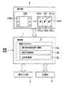
この図1に示されるように、画像表示装置は、全体の制御を司る制御部1と操作入力部3、記憶部4、表示部5からなる。そして、この制御部1は、記憶部4に予め格納されている制御プログラム2を読み出して、実行することで、少なくとも操作説明画面表示機能2a、表示切替機能2b、主制御機能2cを奏することになる。 As shown in FIG. 1, the image display apparatus includes a
尚、制御部1が、各機能2a乃至2cを奏するとき、例えば操作説明画面表示手段、表示切替手段、主制御手段等としての役割を果たすことになる。 When the
このような構成において、制御部1は、主制御機能2cにより、所定の操作画面100を表示部5に表示する。この操作画面100には、各種操作が割り当てられた複数のアイコン100aが表示されている。そして、例えばタッチパネルのような操作入力部3がユーザにより操作されて、所望とする表示態様が選択されると、制御部1は、操作説明画面表示機能2aにより操作説明画面101を一時的に表示する。 In such a configuration, the
即ち、操作入力部3としてのタッチパネルが、この例では3つの領域に分けられており、各領域に所定操作を割り当てているが、操作説明画面101においても、このタッチパネル16の3つの領域101a、101b、101c毎に割り当てられている操作種目が分かるように所定のアイコン101d乃至101fを各領域に表示する。 That is, the touch panel as the operation input unit 3 is divided into three areas in this example, and a predetermined operation is assigned to each area. However, even in the
こうして、ユーザにより操作入力部3が操作されて領域101a乃至101cのいずれかが押下されて選択されると、制御部1は、表示切替機能2bにより表示を切り替えることになる。より具体的には、例えば領域101aが選択されると画面戻し、領域101bが選択されると操作画面100の表示、領域101cが選択されると画面送りが実行される。但し、これには限定されない。各操作は各領域101a乃至101cに予め割り当てられた仕様により定まる。 Thus, when the operation input unit 3 is operated by the user and any one of the
このように、本発明の第1の実施の形態に係る画像表示装置は、
・タッチパネルが所定の領域に分割され、各領域に所定操作が割り当てられる。As described above, the image display apparatus according to the first embodiment of the present invention includes:
A touch panel is divided into predetermined areas, and predetermined operations are assigned to the respective areas.
・フル画面表示に移行する際など、アイコンを消去する場合には、該移行前に上記割り当てが分かるように一時的に操作説明画面を表示する。
といった特徴的な処理を行うことができる。When erasing an icon such as when shifting to a full screen display, an operation explanation screen is temporarily displayed before the transition so that the above assignment can be understood.
Such characteristic processing can be performed.
従って、タッチパネルを用いた操作を簡易且つ適正に行うことができるようになり、アイコンが表示されていない状況(フル画面再生表示)に移行するに際して、操作説明画面でタッチパネルに割り当てられた各操作を把握することが可能となる。 Accordingly, the operation using the touch panel can be performed easily and appropriately, and each operation assigned to the touch panel on the operation explanation screen can be performed when shifting to a state where the icon is not displayed (full screen playback display). It becomes possible to grasp.
次に、本発明の第2の実施の形態について説明する。 Next, a second embodiment of the present invention will be described.
図2には本発明の第2の実施の形態に係る撮像装置の構成を示し説明する。 FIG. 2 shows and describes the configuration of an imaging apparatus according to the second embodiment of the present invention.
これは、前述した第1の実施の形態に係る画像表示装置をデジタルスチルカメラやデジタルビデオカメラ等の撮像装置に適用したものである。以下、詳述する。 In this embodiment, the image display device according to the first embodiment described above is applied to an imaging device such as a digital still camera or a digital video camera. Details will be described below.
この図2に示されるように、第1の実施の形態に係る撮像装置には、撮影レンズ、絞り、フォーカスレンズ等を概念上含むレンズ部11が配設されている。そして、このレンズ部11を介して入射する被写体光の光路上には、CCD(Charge Coupled Device)等の撮像素子12が配置されている。この撮像素子12の出力は、アナログ信号処理部13、アナログ/ディジタル(A/D; Analog/Digital)変換部14を介してディジタル信号処理部15の入力に接続されている。そして、このディジタル信号処理部15の出力は、液晶パネル17、記録デバイス19の入力に電気的に接続されている。 As shown in FIG. 2, the imaging device according to the first embodiment is provided with a
レンズ部11には、それを構成する絞りの調整やフォーカスレンズの移動を行うためのアクチュエータ20が機械的に接続されている。そして、該アクチュエータ20は、その駆動制御を行うためのモータドライバ21に接続されている。 The
さらに、この撮像装置には、全体の制御を司るCPU(Central Processing Unit)23が配設されており、該CPU23は、モータドライバ21、タイミングジェネレータ(TG; Timing Generator)22、操作部24、EEPROM(Electrically Erasable Programmable ROM)25、プログラムROM(Read Only Memory)26、RAM(Random Access Memory)27、タッチパネル16と接続されている。尚、CPU23がプログラムROM26に格納された制御プログラムを読み出し、実行することで、制御手段、特に操作説明画面表示手段、表示切替手段、主制御手段等として機能する。 Further, this imaging apparatus is provided with a CPU (Central Processing Unit) 23 that controls the entire control. The CPU 23 includes a
タッチパネル16と液晶パネル17とでタッチスクリーン18が構成される。 A
記録デバイス19は、例えばDVD(Digital Versatile Disc)等のディスクやメモリカード等の半導体メモリその他のリムーバブルな記録媒体であり、撮像装置本体に対して着脱自在となっている。EEPROM25は、設定された各種情報その他の電源がオフにされたときも保持すべきデータ等を記憶する為のものである。プログラムROM26は、CPU23が実行するプログラム、該プログラムを実行する上で必要なデータを記憶する為のものである。そして、RAM27は、CPU23が各種処理を実行する際のワークエリアとして必要なプログラムやデータを一時記憶する為のものである。 The
このような構成において、CPU23は、プログラムROM26に記録されているプログラムを実行することにより撮像装置を構成する各部を制御し、タッチパネル16からの信号や、操作部24からの信号に応じて、所定の処理を実行する。操作部24は、ユーザによって操作されるもので、該操作に対応した信号をCPU23に供給する。 In such a configuration, the CPU 23 controls each unit constituting the imaging apparatus by executing a program recorded in the
すなわち、タッチパネル16の任意の位置に指が触れる等して押下されると、つまりユーザにより所定の操作入力がなされると、該タッチパネル16より押下された位置の座標が検出され、当該座標に係る信号がCPU23に送出され、該CPU23は該座標に対応する所定の情報を取得し、該情報に基づいて所定の処理を実行する。 That is, when a finger touches an arbitrary position on the touch panel 16 or the like, that is, when a predetermined operation input is made by the user, the coordinates of the position pressed by the touch panel 16 are detected, and the coordinates related to the coordinates are detected. A signal is sent to the CPU 23, and the CPU 23 acquires predetermined information corresponding to the coordinates and executes predetermined processing based on the information.
レンズ部1を介して被写体光が入射すると、撮像素子12は被写体光を撮像し、光電変換し、アナログの画像信号を出力する。このとき、モータドライバ21は、CPU23の制御に基づきアクチュエータ20を駆動する。この駆動により、レンズ部11は、撮像装置の筐体から露出/収納される。また、この駆動により、レンズ部11を構成する絞りの調整や、レンズ部11を構成するフォーカスレンズの移動が行われる。 When subject light enters through the
さらに、タイミングジェネレータ22は、CPU23の制御に基づいて、タイミング信号を撮像素子12に供給する。このタイミング信号により撮像素子12における露出時間等が制御される。撮像素子12は、このタイミングジェネレータ22から供給されるタイミング信号に基づいて動作することにより、レンズ部11を介して入射する被写体からの光を受光して光電変換を行い、受光量に応じた電気信号としてのアナログの画像信号を、アナログ信号処理部13に供給する。アナログ信号処理部13は、CPU23の制御に基づいて、撮像素子12から送出されたアナログの画像信号に対してアナログ信号処理(増幅等)を行い、その結果得られる画像信号を、A/D変換部14に供給する。 Further, the
その後、A/D変換部14は、CPU23の制御に基づいて、アナログ信号処理部13からのアナログの画像信号をA/D変換し、その結果得られるディジタルの画像データをディジタル信号処理部15に供給することになる。ディジタル信号処理部15は、CPU23の制御に基づいてA/D変換部14からのディジタルの画像信号に対し、ノイズ除去処理等のディジタル信号処理を施し、液晶パネル17に供給して表示させる。 Thereafter, the A /
ディジタル信号処理部15は、A/D変換部14からのディジタルの画像信号を、例えばJPEG(Joint Photographic Experts Group)方式等で圧縮し、その結果、得られる圧縮されたディジタルの画像信号を、記録デバイス19に供給して記録させる。 The digital
更に、ディジタル信号処理部15は、記録デバイス19に記録された圧縮された画像データを伸張し、その結果得られる画像データを液晶パネル17に供給して表示させる。つまり、ディジタル信号処理部15は、A/D変換部14からの画像データを、液晶パネル17に供給し、これにより液晶パネル11では所謂スルー画が表示される。その他、ディジタル信号処理部15は、CPU23の制御に基づいて、フォーカスの制御に用いるフォーカス枠(AF枠)の画像を生成し、液晶パネル17に供給して表示させる。 Further, the digital
その後、ユーザが操作部24に概念上含まれるシャッタボタンを押下すると、操作部24からレリーズ信号がCPU23に供給される。このようにして、レリーズ信号がCPU23に供給されると、該CPU23はディジタル信号処理部15を制御し、A/D変換部14からディジタル信号処理部15に供給された画像データを圧縮させ、この圧縮された画像データを記録デバイス19に記録させることになる。 Thereafter, when the user presses a shutter button that is conceptually included in the
この撮像装置は、AF機能を有している。この実施の形態に係る撮像装置では、撮像素子12によって撮像された画像上にAF枠が設定され、そのAF枠の内部の画像に基づいてフォーカスが制御される。このAF機能では、AF枠を、液晶パネル17に表示された画像上の任意の位置に設定することができるようになっており、さらに、液晶パネル17と一体的に構成されたタッチパネル16に対する操作だけで、その位置やサイズ等の制御を行うことができるようになっている。AF処理は、CPU23がプログラムROM26のプログラムを読み出して実行することで実現されることになる。 This imaging apparatus has an AF function. In the imaging apparatus according to this embodiment, an AF frame is set on an image captured by the
ここで、特に特徴的なのは、以下の点である。即ち、CPU23は、所定の操作画面を液晶パネル17に表示する。そして、タッチパネル16がユーザにより操作されて、所望とする表示態様が選択されると、CPU23は、操作説明画面を一時的に表示する。 Here, the following features are particularly characteristic. That is, the CPU 23 displays a predetermined operation screen on the
即ち、タッチパネル16が3つの領域に分けられており、各領域に所定操作が割り当てられているが、操作説明画面においても、このタッチパネル16の3つの領域毎に割り当てられている操作種目が分かるように所定のアイコンを各領域に表示する。 That is, the touch panel 16 is divided into three areas, and a predetermined operation is assigned to each area. On the operation explanation screen, the operation type assigned to each of the three areas of the touch panel 16 can be seen. A predetermined icon is displayed in each area.
こうして、ユーザによりタッチパネル16の領域のいずれかがタップされて選択されると、CPU23は、表示を切り替える。 Thus, when one of the areas of the touch panel 16 is tapped and selected by the user, the CPU 23 switches the display.
以上説明したように、本発明の第2の実施の形態に係る撮像装置では、タッチパネル16が所定の領域に分割され、各領域に所定操作が割り当てられており、フル画面表示に移行する際など、アイコンを消去する場合には、該移行前に上記割り当てが分かるように一時的に操作説明画面を表示するといった特徴的な処理を行うことができる。従って、タッチパネル16を用いた操作を簡易且つ適正に行うことができるようになり、アイコンが表示されていない状況に移行するに際して、操作説明画面でタッチパネル16に割り当てられた各操作を把握することが可能となる。 As described above, in the imaging apparatus according to the second embodiment of the present invention, the touch panel 16 is divided into predetermined areas, and predetermined operations are assigned to the respective areas, and the transition to full screen display is performed. When deleting the icon, it is possible to perform a characteristic process such as temporarily displaying an operation explanation screen so that the above-mentioned assignment can be understood before the transition. Therefore, the operation using the touch panel 16 can be performed easily and appropriately, and each operation assigned to the touch panel 16 can be grasped on the operation explanation screen when shifting to a state where no icon is displayed. It becomes possible.
次に、図3には本発明の第2の実施の形態に係る撮像装置の概観図を示し説明する。 Next, FIG. 3 shows an overview of an image pickup apparatus according to the second embodiment of the present invention.
図3(a)は該撮像装置の後方斜視図であり、図3(b)は前方斜視図である。 FIG. 3A is a rear perspective view of the imaging apparatus, and FIG. 3B is a front perspective view.
撮像装置の前面はレンズカバーで覆われており、該前面のレンズカバー57が下方に開かれると、レンズ部11に概念上含まれる撮影レンズ55とAFイルミネータ56が露呈するように配置されている。このAFイルミネータ56は、セルフタイマランプを兼ねている。撮像装置の上面には、ズームレバー(TELE/WIDE)51とシャッタボタン52、再生ボタン53、パワーボタン54が配置されている。更に、撮像装置の後面には、タッチスクリーン18が設けられている。ズームレバー51、シャッタボタン52、再生ボタン53、パワーボタン54は、操作部24に概念上含まれる。 The front surface of the image pickup apparatus is covered with a lens cover. When the
以下、図4のフローチャートを参照して、本発明の第2の実施の形態に係る撮像装置による特徴的な処理について詳細に説明する。尚、以下の一連の処理は、第2の実施の形態に係る画像表示方法にも相当するものである。 Hereinafter, with reference to the flowchart of FIG. 4, characteristic processing performed by the imaging apparatus according to the second embodiment of the present invention will be described in detail. The following series of processing corresponds to the image display method according to the second embodiment.
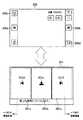
以下では、図5を適宜参照する。図5(a)に示されるように、初期画面200においては、例えば、画面戻し釦200a、画面送り釦200b、スライドショー再生釦200c、画面切替釦200dが表示されている。 Hereinafter, FIG. 5 will be referred to as appropriate. As shown in FIG. 5A, on the
そして、初期画面200において、画面切替釦200dがタップされる等して画面の切り替えが指示されて、フル画面再生に移行すると(ステップS1)、CPU23は先ず操作説明画面201を表示し(ステップS2)、所定時間経過するまで該表示を継続し(ステップS3)、所定時間を経過すると(ステップS3をYesに分岐)、操作説明画面201を消去する(ステップS4)。即ち、フル画面再生表示を行う。 Then, on the
以上の処理によれば、アイコン表示がなされないフル画面再生に移行する前に、タッチパネル16の各領域に割り当てられた操作を把握することができる。即ち、ユーザは、タッチパネル16の各領域201a乃至201cに割り当てられた操作を、各領域201a乃至201cに表示されたアイコン201d乃至201fにより把握できる。According to the above processing, the operation assigned to each area of the touch panel 16 can be grasped before shifting to full screen reproduction in which no icon is displayed. That is, the user can grasp the operations assigned to the
こうして、CPU23は、タッチパネル16の中央領域201bがタップされたか否かを判断し(ステップS5)、中央領域201bがタップされたと判断すると(ステップS5をYesに分岐)、初期画面200を表示し(ステップS6)、処理を終了する。Thus, the CPU 23 determines whether or not the
一方、ステップS5において、CPU23は、中央領域201bがタップされていないと判断した場合には(ステップS5をNoに分岐)、CPU23は、左領域201aがタップされているか否かを判断し(ステップS7)、左領域201aがタップされていると判断した場合には(ステップS7をYesに分岐)、一つ前の撮像画像に係る画面を表示し(画面戻し)(ステップS8)、処理を終了する。一方、CPU23は、左領域201aがタップされていないと判断した場合には(ステップS7をNoに分岐)、右領域201cがタップされたものと判断し、次の撮像画像に係る画面を表示し(画面送り)(ステップS9)、一連の処理を終了することになる。 On the other hand, when the CPU 23 determines in step S5 that the
以上説明したように、本発明の第1及び第2の実施の形態によれば、タッチパネルを用いた操作を簡易且つ適正に行うことができるようになり、特にアイコンが表示されていない状況(例えば、撮像画像のフル画面表示)に移行するに際して、操作説明画面でタッチパネルに割り当てられた各操作を把握することが可能となる。 As described above, according to the first and second embodiments of the present invention, the operation using the touch panel can be performed easily and appropriately, and in particular the situation where no icon is displayed (for example, When shifting to a full screen display of a captured image, it is possible to grasp each operation assigned to the touch panel on the operation explanation screen.
以上、本発明の第1及び第2の実施の形態について説明したが、本発明はこれに限定されることなくその趣旨を逸脱しない範囲で種々の改良・変更が可能である。 The first and second embodiments of the present invention have been described above, but the present invention is not limited to this, and various improvements and modifications can be made without departing from the spirit of the present invention.
例えば、上記第1及び第2の実施の形態では、操作説明画面として、タッチパネルの3つの領域に割り当てられた各機能を説明するものを例示して説明したが、これに限定されず、アイコンに加えて、簡単な操作説明を表示するようにしてもよい。 For example, in the first and second embodiments described above, the operation explanation screen has been exemplified by explaining each function assigned to the three areas of the touch panel. In addition, a simple operation description may be displayed.
1…制御部、2…制御プログラム、2a…操作説明画面表示機能、2b…表示切替機能、2c…主制御機能、3…操作入力部、4…記憶部、5…表示部、11…レンズ部、12…撮像素子、13…アナログ信号処理部、14…A/D変換部、15…ディジタル信号処理部、16…タッチパネル、17…液晶パネル、18…タッチスクリーン、19…記録デバイス、20…アクチュエータ、21…モータドライバ、22…タイミングジェネレータ、23…CPU、24…操作部、25…EEPROM、26…プログラムROM、27…RAM、100…メニュー画面、101…操作説明画面、101a…左領域、101b…中央領域、101c…右領域 DESCRIPTION OF
Claims (5)
Translated fromJapaneseタッチパネルは複数の領域に分けられると共に、各領域に所定の操作が割り当てられ、
フル画面表示に移行する際は、該移行前に上記タッチパネルの各領域毎に割り当てられている操作種目が分かるように上記表示部に表示される操作説明画面の各領域に所定のアイコンが所定時間に亘り表示され、
上記操作説明画面が消去され、フル画面表示に移行した後に上記タッチパネルの一の領域が押下されると、制御部によって該領域に割り当てられた操作を行うように制御する
ことを特徴とする画像表示装置。At least an image is displayed on the display,
The touch panel is divided into a plurality of areas, and a predetermined operation is assigned to each area.
When shifting to the full screen display, a predetermined icon is displayed in each area of the operation explanation screen displayed on the display unit for a predetermined time so that an operation type assigned to each area of the touch panel can be understood before the transition. Displayed,
When the operation explanation screen is erased and one area of the touch panel is pressedafter shifting to the full screen display , the control unit controls to perform an operation assigned to the area. apparatus.
ことを特徴とする請求項1に記載の画像表示装置。The touch panel is divided into three areas: the left area displays the previous image, the center area shifts to the menu screen, and the right area allocates the next image display as the predetermined operation. The image display apparatus according to claim 1.
少なくとも上記画像信号に基づいて撮像画像を表示する表示部と、
複数の領域に分けられると共に、各領域に所定の操作が割り当てられたタッチパネルと、
フル画面表示処理を開始すると、上記表示部に所定の操作説明画面を所定時間に亘り表示し、該操作説明画面においては、上記タッチパネルの各領域毎に割り当てられている操作種目が分かるように所定のアイコンが各領域に表示されることにより、各領域に割り当てられた操作の内容を提示し、上記操作説明画面が消去され、フル画面表示に移行した後に上記タッチパネルの一の領域が押下されると、該領域に割り当てられた操作を行うように制御する制御部とを備えた
ことを特徴とする撮像装置。An imaging unit that captures a subject image and obtains an image signal;
A display unit that displays a captured image based on at least the image signal;
A touch panel that is divided into a plurality of areas and assigned a predetermined operation to each area;
Upon starting the full screen display process, a predetermined operation manual screen on the display unit displayed for a predetermined time, Oiteto the operation description screen, so that the operation events allocated to each region of the touch panel is found By displaying a predetermined icon in each area, the contents of the operation assigned to each area are presented, theoperation explanation screen is erased, and after shifting to full screen display, one area of the touch panel is pressed. And a control unit that performs control so as to perform an operation assigned to the area.
上記操作説明画面においては、タッチパネルの複数に分割された各領域毎に割り当てられている操作種目が分かるように所定のアイコンが各領域に表示されることにより、各領域に割り当てられた操作の内容を提示するステップと、
上記操作説明画面が消去され、フル画面表示に移行した後に上記タッチパネルの一の領域が押下されると、該領域に割り当てられた操作を行うように制御するステップとを有する
ことを特徴とする画像表示方法。When the full screen display process is started, a step of displaying a predetermined operation explanation screen on the display unit for a predetermined time;
In the above operation explanation screen, a predetermined icon is displayed in each area so that an operation type assigned to each area divided into a plurality of areas on the touch panel is displayed, so that the contents of the operation assigned to each area are displayed. Presenting steps,
And the step of controlling to perform an operation assigned to the area when the area of the touch panel is pressedafter the operation explanation screen is erased and the display shifts to the full screen display. Display method.
フル画面表示処理を開始すると、表示部に所定の操作説明画面を所定時間に亘り表示する操作説明画面表示機能と、
上記操作説明画面においては、タッチパネルの複数に分割された各領域毎に割り当てられている操作種目が分かるように所定のアイコンが各領域に表示されることにより、各領域に割り当てられた操作の内容を提示し、上記操作説明画面が消去され、フル画面表示に移行した後に上記タッチパネルの一の領域が押下されると、該領域に割り当てられた表示の切り替えを行なう表示切替機能とを奏する
ことを特徴とするプログラム。Computer
When the full screen display process is started, an operation explanation screen display function for displaying a predetermined operation explanation screen on the display unit for a predetermined time;
In the above operation explanation screen, a predetermined icon is displayed in each area so that an operation type assigned to each area divided into a plurality of areas on the touch panel is displayed, so that the contents of the operation assigned to each area are displayed. When the area of the touch panel is pressedafter the operation explanation screen is erased and the screen is shifted to the full screen display, the display switching function for switching the display assigned to the area is performed. A featured program.
Priority Applications (10)
| Application Number | Priority Date | Filing Date | Title |
|---|---|---|---|
| JP2007171246AJP5088017B2 (en) | 2007-06-28 | 2007-06-28 | Image display apparatus, imaging apparatus, image display method, and program |
| EP08752542AEP2161652B1 (en) | 2007-06-28 | 2008-05-09 | Image display device, imaging device, image display method, and program |
| CN200880022000.4ACN101689081B (en) | 2007-06-28 | 2008-05-09 | Image display device, imaging device, image display method, and program |
| RU2009147444/08ARU2451984C2 (en) | 2007-06-28 | 2008-05-09 | Image display apparatus, image forming apparatus, image display method and programme |
| PCT/JP2008/058659WO2009001622A1 (en) | 2007-06-28 | 2008-05-09 | Image display device, imaging device, image display method, and program |
| BRPI0813661-0A2ABRPI0813661A2 (en) | 2007-06-28 | 2008-05-09 | IMAGE EXHIBITION APPARATUS AND METHOD, IMAGE TRAINING APPARATUS, AND, PROGRAM |
| KR1020097026890AKR101439578B1 (en) | 2007-06-28 | 2008-05-09 | Image display device, imaging device, image display method, and computer-readable recording medium storing program |
| US12/601,838US8488038B2 (en) | 2007-06-28 | 2008-05-09 | Image display apparatus, imaging apparatus, image display method, and program |
| TW097122286ATW200908712A (en) | 2007-06-28 | 2008-06-13 | Image display device, imaging device, image display method, and program |
| US13/869,602US8704930B2 (en) | 2007-06-28 | 2013-04-24 | Image display apparatus, imaging apparatus, image display method, and program |
Applications Claiming Priority (1)
| Application Number | Priority Date | Filing Date | Title |
|---|---|---|---|
| JP2007171246AJP5088017B2 (en) | 2007-06-28 | 2007-06-28 | Image display apparatus, imaging apparatus, image display method, and program |
Publications (2)
| Publication Number | Publication Date |
|---|---|
| JP2009010774A JP2009010774A (en) | 2009-01-15 |
| JP5088017B2true JP5088017B2 (en) | 2012-12-05 |
Family
ID=40185445
Family Applications (1)
| Application Number | Title | Priority Date | Filing Date |
|---|---|---|---|
| JP2007171246AExpired - Fee RelatedJP5088017B2 (en) | 2007-06-28 | 2007-06-28 | Image display apparatus, imaging apparatus, image display method, and program |
Country Status (9)
| Country | Link |
|---|---|
| US (2) | US8488038B2 (en) |
| EP (1) | EP2161652B1 (en) |
| JP (1) | JP5088017B2 (en) |
| KR (1) | KR101439578B1 (en) |
| CN (1) | CN101689081B (en) |
| BR (1) | BRPI0813661A2 (en) |
| RU (1) | RU2451984C2 (en) |
| TW (1) | TW200908712A (en) |
| WO (1) | WO2009001622A1 (en) |
Cited By (2)
| Publication number | Priority date | Publication date | Assignee | Title |
|---|---|---|---|---|
| US8617398B2 (en) | 1996-08-12 | 2013-12-31 | Debasish Mukhopadhyay | Method for high efficiency reverse osmosis operation |
| US8758720B2 (en) | 1996-08-12 | 2014-06-24 | Debasish Mukhopadhyay | High purity water produced by reverse osmosis |
Families Citing this family (20)
| Publication number | Priority date | Publication date | Assignee | Title |
|---|---|---|---|---|
| USD609714S1 (en)* | 2007-03-22 | 2010-02-09 | Fujifilm Corporation | Electronic camera |
| JP4370535B2 (en) | 2007-06-28 | 2009-11-25 | ソニー株式会社 | Image display device, imaging device, image display control method, and program |
| US9081464B2 (en)* | 2009-11-20 | 2015-07-14 | Adobe Systems Incorporated | Object selection |
| CN102419678B (en)* | 2010-09-28 | 2014-10-15 | 纬创资通股份有限公司 | Composite display device and display control method thereof |
| US8773568B2 (en)* | 2010-12-20 | 2014-07-08 | Samsung Electronics Co., Ltd | Imaging apparatus and method for improving manipulation of view finders |
| WO2012096419A1 (en)* | 2011-01-14 | 2012-07-19 | Lg Electronics Inc. | Electronic device and method of controlling the same |
| KR101758164B1 (en)* | 2011-04-08 | 2017-07-26 | 엘지전자 주식회사 | Mobile twrminal and 3d multi-angle view controlling method thereof |
| JP2013026664A (en)* | 2011-07-15 | 2013-02-04 | Olympus Imaging Corp | External apparatus, camera system, image pickup method, and program |
| JP5929719B2 (en) | 2012-11-12 | 2016-06-08 | ソニー株式会社 | Information processing apparatus, communication system, and information processing method |
| JP5921427B2 (en)* | 2012-12-27 | 2016-05-24 | キヤノン株式会社 | Imaging control apparatus and control method thereof |
| KR20140085061A (en)* | 2012-12-27 | 2014-07-07 | 삼성전자주식회사 | Display apparatus and Method for controlling display apparatus thereof |
| JP6113090B2 (en)* | 2013-03-21 | 2017-04-12 | 株式会社沖データ | Information processing apparatus, image forming apparatus, and touch panel |
| CN103491298B (en)* | 2013-09-13 | 2017-01-25 | Tcl移动通信科技(宁波)有限公司 | Multi-region real-time synthesis photographing method and touch control terminal |
| CN105706436B (en)* | 2013-11-14 | 2019-04-16 | 索尼公司 | Information processing unit, imaging device, imaging system, the control method of information processing unit, the control method of imaging device and computer-readable medium |
| JP2015172836A (en) | 2014-03-11 | 2015-10-01 | キヤノン株式会社 | Display control apparatus and display control method |
| DE102014210893A1 (en)* | 2014-06-06 | 2015-12-17 | Siemens Aktiengesellschaft | Method for operating an image recording device with touch screen and image recording device |
| WO2016035422A1 (en) | 2014-09-05 | 2016-03-10 | 富士フイルム株式会社 | Operating apparatus, operating method, and program for image capturing apparatus |
| JP6277354B2 (en)* | 2016-11-01 | 2018-02-14 | 株式会社ユピテル | Electronics |
| JP6682067B2 (en)* | 2019-02-26 | 2020-04-15 | 株式会社ユピテル | Electronics |
| JP6830633B2 (en)* | 2020-01-21 | 2021-02-17 | 株式会社ユピテル | Electronics |
Family Cites Families (15)
| Publication number | Priority date | Publication date | Assignee | Title |
|---|---|---|---|---|
| JPH03189812A (en)* | 1989-12-20 | 1991-08-19 | Hitachi Ltd | operating device |
| JPH0877493A (en)* | 1994-09-08 | 1996-03-22 | Fujitsu Ten Ltd | Display device |
| JP3189812B2 (en) | 1998-11-12 | 2001-07-16 | 日本電気株式会社 | Burn-in test jig for semiconductor device and burn-in test method |
| FI20001506A7 (en)* | 1999-10-12 | 2001-04-13 | Myorigo Oy | Handheld device operating method |
| JP4882151B2 (en)* | 2000-12-27 | 2012-02-22 | ソニー株式会社 | Information processing apparatus, information processing method, recording medium, and image processing apparatus |
| JP2004104594A (en)* | 2002-09-11 | 2004-04-02 | Toshiba Corp | Digital still camera and user instruction input method |
| JP2006040050A (en)* | 2004-07-28 | 2006-02-09 | Olympus Corp | Reproduction device, camera and display switching method for reproduction device |
| US9727082B2 (en)* | 2005-04-26 | 2017-08-08 | Apple Inc. | Back-side interface for hand-held devices |
| JP4945961B2 (en)* | 2005-08-30 | 2012-06-06 | ソニー株式会社 | Imaging device |
| JP4883413B2 (en)* | 2007-06-28 | 2012-02-22 | ソニー株式会社 | Imaging apparatus, image display control method, and program |
| JP2009010775A (en) | 2007-06-28 | 2009-01-15 | Sony Corp | Image display device, imaging device, image display method, and program |
| JP2009010776A (en)* | 2007-06-28 | 2009-01-15 | Sony Corp | Imaging device, photography control method, and program |
| JP4370535B2 (en) | 2007-06-28 | 2009-11-25 | ソニー株式会社 | Image display device, imaging device, image display control method, and program |
| JP2009010777A (en)* | 2007-06-28 | 2009-01-15 | Sony Corp | Imaging device, photography control method, and program |
| KR101506488B1 (en)* | 2008-04-04 | 2015-03-27 | 엘지전자 주식회사 | Portable terminal using proximity sensor and control method thereof |
- 2007
- 2007-06-28JPJP2007171246Apatent/JP5088017B2/ennot_activeExpired - Fee Related
- 2008
- 2008-05-09EPEP08752542Apatent/EP2161652B1/ennot_activeNot-in-force
- 2008-05-09KRKR1020097026890Apatent/KR101439578B1/ennot_activeExpired - Fee Related
- 2008-05-09USUS12/601,838patent/US8488038B2/ennot_activeExpired - Fee Related
- 2008-05-09WOPCT/JP2008/058659patent/WO2009001622A1/enactiveApplication Filing
- 2008-05-09RURU2009147444/08Apatent/RU2451984C2/ennot_activeIP Right Cessation
- 2008-05-09BRBRPI0813661-0A2Apatent/BRPI0813661A2/ennot_activeIP Right Cessation
- 2008-05-09CNCN200880022000.4Apatent/CN101689081B/ennot_activeExpired - Fee Related
- 2008-06-13TWTW097122286Apatent/TW200908712A/enunknown
- 2013
- 2013-04-24USUS13/869,602patent/US8704930B2/ennot_activeExpired - Fee Related
Cited By (3)
| Publication number | Priority date | Publication date | Assignee | Title |
|---|---|---|---|---|
| US8617398B2 (en) | 1996-08-12 | 2013-12-31 | Debasish Mukhopadhyay | Method for high efficiency reverse osmosis operation |
| US8641905B2 (en) | 1996-08-12 | 2014-02-04 | Debasish Mukhopadhyay | Method for high efficiency reverse osmosis operation |
| US8758720B2 (en) | 1996-08-12 | 2014-06-24 | Debasish Mukhopadhyay | High purity water produced by reverse osmosis |
Also Published As
| Publication number | Publication date |
|---|---|
| EP2161652B1 (en) | 2012-06-27 |
| RU2451984C2 (en) | 2012-05-27 |
| KR101439578B1 (en) | 2014-09-11 |
| US20130235248A1 (en) | 2013-09-12 |
| JP2009010774A (en) | 2009-01-15 |
| CN101689081A (en) | 2010-03-31 |
| KR20100036262A (en) | 2010-04-07 |
| US20100214465A1 (en) | 2010-08-26 |
| CN101689081B (en) | 2015-05-20 |
| WO2009001622A1 (en) | 2008-12-31 |
| US8704930B2 (en) | 2014-04-22 |
| EP2161652A1 (en) | 2010-03-10 |
| RU2009147444A (en) | 2011-06-27 |
| US8488038B2 (en) | 2013-07-16 |
| BRPI0813661A2 (en) | 2014-12-30 |
| EP2161652A4 (en) | 2010-08-25 |
| TW200908712A (en) | 2009-02-16 |
Similar Documents
| Publication | Publication Date | Title |
|---|---|---|
| JP5088017B2 (en) | Image display apparatus, imaging apparatus, image display method, and program | |
| US7999872B2 (en) | Image display device, image pickup apparatus, image display control method, and program | |
| JP4883413B2 (en) | Imaging apparatus, image display control method, and program | |
| JP5652652B2 (en) | Display control apparatus and method | |
| JP2009010775A (en) | Image display device, imaging device, image display method, and program | |
| JP5617603B2 (en) | Display control apparatus, display control method, and program | |
| US8823864B2 (en) | Image capturing apparatus and associated methodology for auto-focus and facial detection | |
| US20090080930A1 (en) | Imaging device and its control method | |
| JP2012104994A (en) | Input device, input method, program, and recording medium | |
| JP2019086701A (en) | Imaging control apparatus and control method thereof | |
| JP5131253B2 (en) | Image display device, imaging device, image display control method, and program | |
| JP5863418B2 (en) | Imaging apparatus and control method thereof | |
| JP2005345811A (en) | Camera that can set the operation member function | |
| JP2006253943A (en) | Digital camera | |
| JP2015088776A (en) | Image processing device, image processing method and program | |
| JP2003348518A (en) | Digital camera | |
| JP2011077862A (en) | Imaging apparatus, and program | |
| JP2009060436A (en) | Camera |
Legal Events
| Date | Code | Title | Description |
|---|---|---|---|
| A621 | Written request for application examination | Free format text:JAPANESE INTERMEDIATE CODE: A621 Effective date:20100304 | |
| A131 | Notification of reasons for refusal | Free format text:JAPANESE INTERMEDIATE CODE: A131 Effective date:20110804 | |
| A521 | Request for written amendment filed | Free format text:JAPANESE INTERMEDIATE CODE: A523 Effective date:20110921 | |
| A131 | Notification of reasons for refusal | Free format text:JAPANESE INTERMEDIATE CODE: A131 Effective date:20111027 | |
| A521 | Request for written amendment filed | Free format text:JAPANESE INTERMEDIATE CODE: A523 Effective date:20111215 | |
| A02 | Decision of refusal | Free format text:JAPANESE INTERMEDIATE CODE: A02 Effective date:20120306 | |
| A521 | Request for written amendment filed | Free format text:JAPANESE INTERMEDIATE CODE: A523 Effective date:20120604 | |
| A911 | Transfer to examiner for re-examination before appeal (zenchi) | Free format text:JAPANESE INTERMEDIATE CODE: A911 Effective date:20120612 | |
| TRDD | Decision of grant or rejection written | ||
| A01 | Written decision to grant a patent or to grant a registration (utility model) | Free format text:JAPANESE INTERMEDIATE CODE: A01 Effective date:20120814 | |
| A01 | Written decision to grant a patent or to grant a registration (utility model) | Free format text:JAPANESE INTERMEDIATE CODE: A01 | |
| A61 | First payment of annual fees (during grant procedure) | Free format text:JAPANESE INTERMEDIATE CODE: A61 Effective date:20120827 | |
| FPAY | Renewal fee payment (event date is renewal date of database) | Free format text:PAYMENT UNTIL: 20150921 Year of fee payment:3 | |
| R151 | Written notification of patent or utility model registration | Ref document number:5088017 Country of ref document:JP Free format text:JAPANESE INTERMEDIATE CODE: R151 | |
| FPAY | Renewal fee payment (event date is renewal date of database) | Free format text:PAYMENT UNTIL: 20150921 Year of fee payment:3 | |
| R250 | Receipt of annual fees | Free format text:JAPANESE INTERMEDIATE CODE: R250 | |
| R250 | Receipt of annual fees | Free format text:JAPANESE INTERMEDIATE CODE: R250 | |
| R250 | Receipt of annual fees | Free format text:JAPANESE INTERMEDIATE CODE: R250 | |
| R250 | Receipt of annual fees | Free format text:JAPANESE INTERMEDIATE CODE: R250 | |
| R250 | Receipt of annual fees | Free format text:JAPANESE INTERMEDIATE CODE: R250 | |
| LAPS | Cancellation because of no payment of annual fees |