JP5083635B2 - Acceleration sensor - Google Patents
Acceleration sensorDownload PDFInfo
- Publication number
- JP5083635B2 JP5083635B2JP2009258903AJP2009258903AJP5083635B2JP 5083635 B2JP5083635 B2JP 5083635B2JP 2009258903 AJP2009258903 AJP 2009258903AJP 2009258903 AJP2009258903 AJP 2009258903AJP 5083635 B2JP5083635 B2JP 5083635B2
- Authority
- JP
- Japan
- Prior art keywords
- acceleration
- beam member
- acceleration sensor
- substrate
- mass body
- Prior art date
- Legal status (The legal status is an assumption and is not a legal conclusion. Google has not performed a legal analysis and makes no representation as to the accuracy of the status listed.)
- Expired - Fee Related
Links
Images


Landscapes
- Pressure Sensors (AREA)
Description
Translated fromJapanese本発明は、加速度センサに関し、特に、静電容量型の加速度センサに関するものである。 The present invention relates to an acceleration sensor, and more particularly to a capacitance type acceleration sensor.
従来、加速度センサの1つとして、加速度にともなう静電容量の変化を検出する静電容量型の加速度センサが使用されている。静電容量型の加速度センサにおいて、広範囲の加速度を検出するための加速度センサが提案されている。 Conventionally, as one of the acceleration sensors, a capacitance type acceleration sensor that detects a change in capacitance accompanying acceleration is used. An acceleration sensor for detecting a wide range of acceleration has been proposed as a capacitance type acceleration sensor.
たとえば、特開2004−286554号公報(特許文献1)には1つのセンサで広範囲の加速度を検出するための加速度センサが提案されている。この公報の加速度センサは、可動電極に接続され、加速度に応じて変位する複数の梁を有している。複数の梁のバネ定数はそれぞれ異なっている。バネ定数の異なる複数の梁として、長さの異なる3つの梁が形成されている。これら3つの梁はそれぞれ2枚構造で構成され、内部に間隔を有している。 For example, Japanese Unexamined Patent Application Publication No. 2004-286554 (Patent Document 1) proposes an acceleration sensor for detecting a wide range of acceleration with one sensor. The acceleration sensor of this publication has a plurality of beams that are connected to the movable electrode and are displaced according to the acceleration. The spring constants of the beams are different. Three beams having different lengths are formed as a plurality of beams having different spring constants. Each of these three beams is constituted by a two-sheet structure and has an interval inside.
この加速度センサでは加速度に応じて最も長い梁から変位する。低G(低い加速度)が印加された場合には最も長い梁が変位し、内部の間隔まで変位すると2枚の梁が接触するので、最も長い梁はそれ以上変位しない。低Gより加速度が高くなると2番目に長い梁が変位し、さらに加速度が高くなると最も短い梁が変位する。このように長さが異なる3つの梁がそれぞれ変位することにより、固定電極と可動電極との間の距離が低Gから高G(高い加速度)までの範囲で追従して変化する。これにより、小さなサイズで広範囲の加速度を検出できると上記公報には記載されている。 This acceleration sensor is displaced from the longest beam according to the acceleration. When a low G (low acceleration) is applied, the longest beam is displaced, and when it is displaced to the internal distance, the two beams are in contact with each other, so that the longest beam is not displaced further. When the acceleration is higher than the low G, the second longest beam is displaced, and when the acceleration is further increased, the shortest beam is displaced. As the three beams having different lengths are displaced in this way, the distance between the fixed electrode and the movable electrode changes following a range from low G to high G (high acceleration). This publication discloses that a wide range of acceleration can be detected with a small size.
この公報の加速度センサでは、低Gより加速度が高くなると最も長い梁から梁の接触が生じる。梁が接触した場合、接触時の衝撃により、梁が破壊されるという問題がある。また、梁が接触し貼り付いたまま剥がれない状態になるという問題がある。なお、梁が接触し貼り付いたまま剥がれない状態はスティッキングと呼ばれる。 In the acceleration sensor of this publication, when the acceleration is higher than the low G, the longest beam contacts the beam. When the beam comes into contact, there is a problem that the beam is broken by an impact at the time of contact. In addition, there is a problem that the beam comes into contact and cannot be peeled off. The state where the beams are in contact and cannot be peeled off is called sticking.
本発明は、上記課題を鑑みてなされたものであり、その目的は、梁部材を接触させることなく、広範囲の加速度を検出できる加速度センサを提供することである。 The present invention has been made in view of the above problems, and an object thereof is to provide an acceleration sensor capable of detecting a wide range of acceleration without bringing a beam member into contact.
本発明の加速度センサは、基板と、基板に支持された梁部材と、基板に対して移動可能に梁部材に支持され、可動電極を有する慣性質量体と、可動電極と対向するように配置された固定電極とを備え、梁部材は、慣性質量体にかかる加速度の方向に伸びており、梁部材は、加速度が大きくなるにつれて変位の変化率が小さくなり、かつ梁部材が縮んで梁部材自体が接触するまでの加速度の方向の梁部材の変位量が加速度がかかった場合の加速度の方向の梁部材の伸びる部分の変位量より大きい。 The acceleration sensor of the present invention is arranged so as to face the movable electrode, a substrate, a beam member supported by the substrate, an inertia mass body supported by the beam member so as to be movable with respect to the substrate, and a movable electrode. The beam member extends in the direction of acceleration applied to the inertial mass body, and the beam member has a smaller rate of change of displacement as the acceleration increases, and the beam member contracts to reduce the beam member itself. The amount of displacement of the beam member in the direction of acceleration until the contact is greater than the amount of displacement of the extending portion of the beam member in the direction of acceleration when acceleration is applied.
本発明の加速度センサによれば、梁部材は慣性質量体にかかる加速度の方向に伸びており、梁部材は加速度が大きくなるにつれて変位の変化率が小さくなり、かつ梁部材が縮んで梁部材自体が接触するまでの加速度の方向の梁部材の変位量が加速度がかかった場合の加速度の方向の梁部材の伸びる部分の変位量より大きいため、梁部材を接触させることなく、広範囲の加速度を検出できる。 According to the acceleration sensor of the present invention, the beam member extends in the direction of acceleration applied to the inertial mass body, and the beam member decreases in rate of displacement as the acceleration increases, and the beam member contracts to reduce the beam member itself. Because the amount of displacement of the beam member in the direction of acceleration until it touches is greater than the amount of displacement of the extending portion of the beam member in the direction of acceleration when acceleration is applied, a wide range of acceleration is detected without contacting the beam member it can.
以下、本発明の実施の形態について図に基づいて説明する。
(実施の形態1)
最初に本発明の実施の形態1の加速度センサの構成について説明する。Hereinafter, embodiments of the present invention will be described with reference to the drawings.
(Embodiment 1)
First, the configuration of the acceleration sensor according to the first embodiment of the present invention will be described.
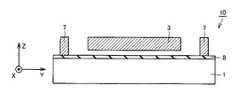
図1〜図4には、説明の便宜のため、座標軸X軸、Y軸、Z軸が導入されている。図1において、X軸は横方向に沿う右方向が正の向きの軸であり、Y軸は縦方向に沿う上方向が正の向きの軸であり、Z軸は紙面に垂直で紙面の上方が正の向きの軸である。なおY軸の方向は、本実施の形態の加速度センサが検出対象とする加速度の方向に一致する。 1-4, coordinate axes X-axis, Y-axis, and Z-axis are introduced for convenience of explanation. In FIG. 1, the X axis is a positive axis in the right direction along the horizontal direction, the Y axis is a positive axis in the upward direction along the vertical direction, and the Z axis is perpendicular to the paper surface and above the paper surface. Is the positive axis. Note that the direction of the Y axis coincides with the direction of acceleration that is detected by the acceleration sensor of the present embodiment.
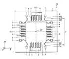
図1を参照して、本実施の形態の加速度センサ10は、基板1と、梁部材2、慣性質量体3と、可動電極4と、固定電極5と、固定電極支持部6と、アンカー7とを主に有している。基板1としては、シリコン基板を用いることができる。また、梁部材2、慣性質量体3、可動電極4、固定電極5、固定電極支持部6およびアンカー7の材質としては、ポリシリコン膜を用いることができる。このポリシリコン膜は、低応力であり、かつ厚み方向に応力分布がないことが望ましい。 Referring to FIG. 1, an
図1〜図4を参照して、基板1にアンカー7が支持されている。梁部材2は、複数の第1梁2aおよび第2梁2bを有している。複数の第1梁2aおよび第2梁2bは、それぞれアンカー7に支持されている。梁部材2は、アンカー7を介して基板1に支持されている。梁部材2は、慣性質量体3にかかる加速度の方向に伸びるように構成されている。梁部材2は、慣性質量体3の変位を検出する方向に伸びるように構成されている。本実施の形態の加速度センサ10が検出対象とする加速度の方向はY軸方向であるため、梁部材2はY軸方向に伸びている。なお、梁部材2は複数に限定されず、単数であってもよい。 1 to 4, an
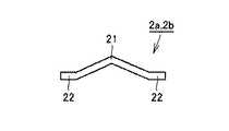
梁部材2は、加速度が大きくなるにつれて変位の変化率が小さくなり、かつ梁部材2が縮んで梁部材2自体が接触するまでの加速度の方向の梁部材2の変位量が加速度がかかった場合の加速度の方向の梁部材2の伸びる部分の変位量より大きくなるように構成されている。本実施の形態では、複数の梁部材2は、それぞれ対向する方向(X軸方向)に湾曲した形状を有している。梁部材2は基板1の表面に対して面内方向に湾曲している湾曲部21を有している。ここで、基板1の表面に対して面内方向とは、基板1の表面に沿った方向を意味する。 When the acceleration of the
湾曲部21の両端には、慣性質量体3にかかる加速度の方向(Y軸方向)に直線状に形成された直線部22が形成されている。梁部材2は加速度の方向に伸びるように構成されているが、より具体的には、梁部材2は直線部22の伸びる方向が加速度の方向と一致するように構成されている。また直線部22は第1梁2aおよび第2梁2bの端部に形成されている。なお、梁部材2は、面内方向における基板1の内側に湾曲していてもよく、また面内方向における基板1の外側に湾曲していてもよい。 At both ends of the bending
また、梁部材2の湾曲する方向はX軸方向に限定されず、たとえば基板1の厚み方向(Z軸方向)に湾曲していてもよい。この場合、梁部材2は、基板1の表面に対して面外方向に湾曲している湾曲部21を有している。ここで、基板1の表面に対して面外方向とは、基板1の表面に沿わない方向を意味する。梁部材2は、基板1の厚み方向の一方面側に湾曲していてもよく、また他方面側に湾曲していてもよい。複数の第1梁2aおよび第2梁2bは、平面視において慣性質量体3の加速度の方向における中心線CL1に対して互いに線対称に配置されている。なお、複数の第1梁2aおよび第2梁2bは、慣性質量体3の加速度の方向における中心線CL1に対して互いに線対称に配置されていなくてもよい。 Further, the direction in which the
慣性質量体3は、基板1に対して移動可能に梁部材2に支持されている。慣性質量体3は、複数の可動電極4を有している。可動電極4は、慣性質量体3の変位にともなって変位するように構成されている。可動電極4は、少なくとも、その一部が導電性を有している。なお、可動電極4は複数に限定されず、単数であってもよい、また、本実施の形態では、可動電極4は、慣性質量体3の両側に形成されているが、これに限定されず、一方側にのみ形成されていてもよい。 The
固定電極5は、慣性質量体3にかかる加速度の方向に可動電極4と対向するように配置されている。可動電極4と固定電極5とは梁部材2が伸びる方向で対向するように配置されている。固定電極5は、対向する可動電極4に対して、Y軸の正方向(図1上側)に配置されていてもよく、またY軸の負方向(図1下側)に配置されていてもよい。固定電極5は、少なくとも、その一部が導電性を有している。固定電極5は固定電極支持部6に支持されている。固定電極支持部6は基板1に支持されている。 The fixed
可動電極4と固定電極5とは静電容量を構成している。可動電極4と固定電極5とは、慣性質量体3の変位によって、静電容量が変化するように構成されている。基板1との絶縁を保つために可動電極4および固定電極5は、絶縁膜8を介して基板1上に形成されている。基板1との絶縁を保つために固定電極支持部6およびアンカー7も絶縁膜8を介して基板1上に形成されている。なお、絶縁膜8としては、低応力の窒化シリコン膜やシリコン酸化膜が好適である。 The
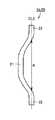
なお、梁部材2は上記の形状に限定されず、たとえば、梁部材2の第1梁2aおよび第2梁2bは、図5〜図7に示される形状であってもよい。図5を参照して、この変形例1の第1梁2aおよび第2梁2bでは、湾曲部21が楕円形状に構成されている。図6を参照して、この変形例2の第1梁2aおよび第2梁2bでは、湾曲部21がその中央部の1箇所で屈曲するように構成されている。図7を参照して、この変形例3の第1梁2aおよび第2梁2bでは、湾曲部21が直線部22と直角に連続するように構成されている。 In addition, the
次に、本実施の形態の加速度センサの梁部材の動作について説明する。
図1を参照して、加速度が図1のY軸正方向に印加された場合、慣性質量体3は図1のY軸負方向に変位する。この慣性質量体3の変位にともない図1中上側の複数の第1梁2aは伸び、図1中下側の複数の第2梁2bは縮む。以下、この際の梁部材2の動作について詳細に説明する。Next, the operation of the beam member of the acceleration sensor according to the present embodiment will be described.
Referring to FIG. 1, when acceleration is applied in the positive Y-axis direction of FIG. 1,
図8を参照して、湾曲部21は、梁部材2の第1梁2aおよび第2梁2bの湾曲している部分である。この湾曲部21の長さ、すなわち、梁部材2が縮んだ場合に梁部材2自体が接触する変位量(距離)を変位量Aとする。加速度がかかっていない場合の変位量Aが加速度の方向の梁部材2の第1梁2aおよび第2梁2bの最大変位量となる。 With reference to FIG. 8, the
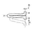
図9を参照して、高Gが印加されて第1梁2aが伸びた場合、最終的には第1梁2aは、たとえば直方体形状となる。この場合の第1梁2aの中心線CL2方向の変位量を変位量Bとする。 Referring to FIG. 9, when high G is applied and
図10および図11を参照して、梁部材2が縮んだ場合の梁部材2の形状について説明する。 The shape of the

変位量Aと変位量Bとの間に式(1)が成り立っていれば、図10に示すように、第2梁2bが縮んだ場合に第2梁2b自体が接触することはない。一方、変位量Aと変位量Bとの間に式(1)が成り立っていなければ、図11に示すように、第2梁2bが縮んだ場合に、第2梁2b自体が接触する。 If Expression (1) is established between the displacement amount A and the displacement amount B, the
変位量Aと変位量Bとの間に式(1)が成り立つためには、加速度方向の梁部材2の第1梁2aおよび第2梁2bの最大変位量が加速度がかかった場合の梁部材2の伸びる部分の変位量より大きければよい。第2梁2bが縮んだ場合、第1梁2aが梁部材2の伸びる部分になる。 In order for Formula (1) to be satisfied between the displacement amount A and the displacement amount B, the beam member when the maximum displacement amount of the
また、変位量Aと変位量Bとの間に式(1)が成り立つようにすれば、第1梁2aと第2梁2bとが慣性質量体3の加速度の方向における中心線CL1に対して互いに線対称に配置されている場合、第2梁2bが縮んでも第2梁2bの中心線CL2方向の変位量は変位量Bを超えないため、第2梁2b自体は接触しない。よって、梁部材2自体は接触しない。 Further, if Expression (1) is established between the displacement amount A and the displacement amount B, the
図12および図13を参照して、梁部材2の第1梁2aおよび第2梁2bの曲げについて説明する。図12を参照して、低Gが印加された場合、加速度によって梁部材2の第1梁2aおよび第2梁2bには力Fが作用するが、第1梁2aおよび第2梁2bの曲げには実質的に力Fの第1梁2aおよび第2梁2bの湾曲方向の分力である力Faが影響する。図13を参照して、高Gが印加された場合、加速度によって梁部材2の第1梁2aおよび第2梁2bには力Fが作用するが、第1梁2aおよび第2梁2bの曲げには実質的に力Fの第1梁2aおよび第2梁2bの湾曲方向の分力である力Fbが影響する。力Faと力Fbとの間には式(2)が成り立っている。 The bending of the
したがって、低Gより高Gの方が梁部材2の第1梁2aおよび第2梁2bの曲げは小さくなる。加速度が大きくなるにしたがって梁部材2の第1梁2aおよび第2梁2bの湾曲方向の分力は小さくなるので、加速度が大きくなるにしたがって梁部材2の曲げの変化率は小さくなる。 Therefore, the bending of the
図14を参照して、本実施の形態の加速度センサの加速度と出力(変位)との関係について説明する。なお、図14では、梁部材2の第1梁2aおよび第2梁2bが慣性質量体3の加速度の方向における中心線CL1に対して互いに線対称に配置された加速度センサ10における加速度と出力(変位)との関係が示されている。 With reference to FIG. 14, the relationship between the acceleration of the acceleration sensor of this Embodiment and an output (displacement) is demonstrated. In FIG. 14, the acceleration and output (in the
低Gが印加された場合、梁部材2の形状は微小にしか変形しない。この梁部材2の形状が微小にしか変形しない領域を微小変形領域とする。この微小変形領域では、加速度によって梁部材2の曲げに作用する力が大きいため、加速度に出力(変位)が比例する出力特性が示される。高Gが印加された場合、梁部材2の形状が大きく変形する。この梁部材2が大きく変化する領域を大変形領域とする。この大変形領域では、加速度によって梁部材2の曲げに作用する力が小さいため、出力の変化が低Gの場合と比べて低下する。 When low G is applied, the shape of the
さらに高い加速度が印加された場合、最終的には梁部材2の伸びる部分が伸びきった状態となる。この梁部材2の伸びる部分が伸びきった状態で梁部材2自体の剛性が変化する領域を梁剛性領域とする。この梁剛性領域では、加速度によって梁部材2の曲げに作用する力がほどんどないため、加速度の変化しても変位はほとんど変化しない。したがって、図11では、加速度が高くになるほど、傾きがなだらかな曲線が描かれる。つまり、加速度が大きくなるにつれて変位の変化率が小さくなる。したがって、1つの梁部材2で広い範囲の加速度が検出可能である。 When a higher acceleration is applied, the part where the
続いて、本実施の形態の加速度センサの加速度の検出原理について説明する。
加速度が図1のY軸正方向に印加された場合を例に加速度の検出原理を説明する。加速度がY軸正方向に加速度センサに加わると、慣性質量体3はY軸負方向に変位する。この慣性質量体3の変位にともなって可動電極4もY軸負方向に変位する。この可動電極4の変位にともなって、図1中右側の可動電極4と固定電極との距離が小さくなり、図1中左側の可動電極4と固定電極との距離が大きくなる。これにより、図1中右側の可動電極4と固定電極5とにより構成される静電容量C1が増大し、図1中左側の可動電極4と固定電極5とにより構成される静電容量C2が減少する。Next, the principle of detecting the acceleration of the acceleration sensor according to the present embodiment will be described.
The acceleration detection principle will be described by taking as an example the case where the acceleration is applied in the positive direction of the Y axis in FIG. When acceleration is applied to the acceleration sensor in the positive Y-axis direction, the inertial
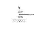
図15を参照して、上記の静電容量C1、C2から加速度検出回路によって加速度が検出される。この加速度検出回路では、静電容量C1と静電容量C2とが直列に接続されている。静電容量C1側の端部には一定電位Vdが印加され、静電容量C2側の端部は接地電位が印加されている。また、上記直列接続部には端子が設けられており、この端子の出力電位Voutを検出することができる。この出力電位Voutは、下記の値となる。 Referring to FIG. 15, the acceleration is detected by the acceleration detection circuit from the capacitances C1 and C2. In this acceleration detection circuit, the capacitance C1 and the capacitance C2 are connected in series. A constant potential Vd is applied to the end portion on the electrostatic capacitance C1 side, and a ground potential is applied to the end portion on the electrostatic capacitance C2 side. The series connection portion is provided with a terminal, and the output potential Vout of this terminal can be detected. This output potential Vout has the following value.
式(3)に示すように、電位Vdは一定値であることから、出力電位Voutを検出することにより、Y軸方向の加速度を検知することができる。なお、加速度が0、すなわち、変位がない場合はC1=C2であるので、Vout=Vd/2で表わされる。 As shown in Expression (3), since the potential Vd is a constant value, the acceleration in the Y-axis direction can be detected by detecting the output potential Vout. When the acceleration is 0, that is, when there is no displacement, C1 = C2, and therefore, Vout = Vd / 2.
続いて、本実施の形態の加速度センサの製造方法について説明する。
図16を参照して、シリコンからなる基板1上に、LPCVD(Low Pressure Chemical Vapor Deposition)法により、絶縁膜8が堆積される。絶縁膜8としては、低応力の窒化シリコン膜やシリコン酸化膜などが適している。この絶縁膜8の上に、PSG(Phosphosilicate Glass)膜101が堆積される。Then, the manufacturing method of the acceleration sensor of this Embodiment is demonstrated.
Referring to FIG. 16, an insulating
主に図17を参照して、固定電極支持部6(図2)が形成される部分のPSG膜101が選択的に除去される。 Referring mainly to FIG. 17, the portion of
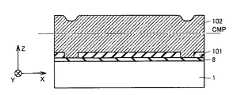
図18を参照して、基板1上全体に、ポリシリコン膜102が堆積される。続いてその表面にCMP(Chemical Mechanical Polishing)処理が施される。 Referring to FIG. 18, a
図19を参照して、上記CMP処理により、ポリシリコン膜102の表面が平坦化される。 Referring to FIG. 19, the surface of
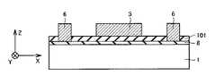
図20を参照して、ポリシリコン膜102のPSG膜101の上面よりも上方の部分に対して、選択的なエッチングが行なわれる。これにより、梁部材2と、慣性質量体3と、可動電極4と、固定電極5と、固定電極支持部6と、アンカー7とが一括形成される。その後、PSG膜101がエッチングにより除去され、図2に示される本実施の形態の加速度センサが得られる。 Referring to FIG. 20, selective etching is performed on a portion of
なお、梁部材2が基板1の厚み方向に湾曲した形状に形成される場合には、PSG膜101に段差エッチングが施され得る。また、ポリシリコン膜102が2段に形成され、その間にPSG膜などの犠牲層を形成され得る。これらにより、梁部材2が基板1の厚み方向に湾曲した形状に形成され得る。 When the
次に、本実施の形態の加速度センサの作用効果について説明する。
本実施の形態の加速度センサによれば、梁部材2は慣性質量体3にかかる加速度の方向に伸びており、梁部材2は加速度が大きくなるにつれて変位の変化率が小さくなり、かつ梁部材2が縮んで梁部材2自体が接触するまでの加速度の方向の梁部材2の変位量が加速度がかかった場合の加速度の方向の梁部材2の伸びる部分の変位量より大きい。そのため、梁部材2が伸びる方向だけでなく梁部材2が縮む方向でも梁部材2を接触させることなく、低Gから高Gまでの広範囲の加速度を検出できる。Next, the function and effect of the acceleration sensor according to the present embodiment will be described.
According to the acceleration sensor of the present embodiment, the
また、梁部材2が接触しないため、梁部材2が接触時の衝撃によって破壊されることを防止できる。また、梁部材2が接触しないため、梁部材2が接触し貼り付いたまま剥がれない状態になることを防止できる。 Moreover, since the
また、梁部材2は、第1梁2aと第2梁2bとを含んでいる。第1梁2aと第2梁2bとは、平面視において慣性質量体3の加速度の方向における中心線CL1に対して互いに線対称に配置されているため、加速度がかかった場合の慣性質量体3の第1梁2aおよび第2梁2bの方向への変位を等しくすることができる。これにより、より正確に加速度を検出できる。 The
また、梁部材2は基板1の表面に対して面内方向に湾曲している湾曲部21を有しているため、梁部材2は加速度が大きくなるにつれて変位の変化率を小さくすることができる。また、湾曲部21が面内方向に湾曲しているため、湾曲部21を製造する際のエッチングが容易であるので、生産効率を向上できる。 Further, since the
また、梁部材2は基板1の表面に対して面外方向に湾曲している湾曲部21を有しているため、梁部材2は加速度が大きくなるにつれて変位の変化率を小さくすることができる。 Moreover, since the
また、固定電極5は、加速度の方向に可動電極4と対向するように配置されているため、加速度の方向と、固定電極5に対する可動電極4の変位の方向とが一致するので、より正確に加速度を検出できる。 In addition, since the fixed
(実施の形態2)
本発明の実施の形態2の加速度センサは、実施の形態1の加速度センサと比較して、梁部材と、可動電極と、固定電極との組が平面視において慣性質量体に対して交差する方向に配置されている点において主に異なっている。(Embodiment 2)
The acceleration sensor according to the second embodiment of the present invention is compared with the acceleration sensor according to the first embodiment in the direction in which the set of the beam member, the movable electrode, and the fixed electrode intersects the inertial mass body in plan view. Is mainly different in that they are arranged in
図21を参照して、本実施の形態の加速度センサ10は、梁部材2と、可動電極4と、固定電極5との組が平面視において慣性質量体3に対して交差する方向に配置されている。慣性質量体3の四方の各々において、可動電極4と固定電極5とが対向して配置されている。対向して配置された可動電極4および固定電極5の両端側に複数の梁部材2が配置されている。複数の第1梁2aおよび第2梁2bは、平面視において慣性質量体3の図21中Y軸方向の加速度の方向における中心線CL1に対して互いに線対称に配置されている。また、複数の第1梁2aおよび第2梁2bは、平面視において慣性質量体3の図21中X軸方向の加速度の方向における中心線CL3に対して互いに線対称に配置されている。梁部材2は複数に限定されず、単数であってもよい。また梁部材2の位置は、慣性質量体3の周囲の四方の各一面における両端部に限定されず、中央部であってもよい。 Referring to FIG. 21,
慣性質量体3の周囲の四方の隣り合う一面に形成された梁部材2と、可動電極4と、固定電極5とは、平面視における慣性質量体3の中心点CPを中心に正負90°回転すると対称となるように構成されている。 The
図21中X軸方向に慣性質量体3を挟んで対称に配置された可動電極4および固定電極5がY軸方向の加速度を検出するように構成されている。また図21中Y軸方向に慣性質量体3を挟んで対称に配置された可動電極4および固定電極5がX軸方向の加速度を検出するように構成されている。 In FIG. 21, the
なお、本実施の形態のこれ以外の構成は、上述した実施の形態1の構成と同様であるため同一の要素については同一の符号を付し、その説明を繰り返さない。また、本実施の形態の製造方法は、上述した実施の形態1の製造方法と同様であるため、その説明を繰り返さない。 In addition, since the structure of this embodiment other than this is the same as that of
本実施の形態の加速度センサ10によれば、梁部材2と、可動電極4と、固定電極5との組が平面視において慣性質量体3に対して交差する方向に配置されているため、基板1の表面に沿った面内の一方向(図21中Y軸方向)の加速度だけでなく、その一方向に対して90°回転した方向(図21中X軸方向)の加速度も検出できる。したがって、本実施の形態の加速度センサ10は、基板1の表面に沿った面内の2軸方向(図21中X軸方向およびY軸方向)の加速度を検出できる。 According to the
(実施の形態3)
本発明の実施の形態3の加速度センサは、実施の形態1の加速度センサと比較して、下部電極をさらに備えている点において主に異なっている。(Embodiment 3)
The acceleration sensor according to the third embodiment of the present invention is mainly different from the acceleration sensor according to the first embodiment in that it further includes a lower electrode.
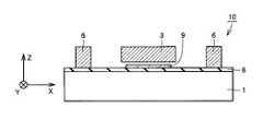
図22および図23を参照して、本実施の形態の加速度センサ10は、実施の形態1の加速度センサ10と比較して、下部電極9をさらに備えている。下部電極9は、基板1と慣性質量体3との間に配置されている。下部電極9は絶縁膜8を介して基板1上に配置されている。 Referring to FIGS. 22 and 23,
慣性質量体3と下部電極9とは静電容量を構成している。慣性質量体3と下部電極9とは、慣性質量体3の変位によって、静電容量が変化するように構成されている。この静電容量の変化より、基板1の厚み方向(図22中Z軸方向)の加速度が検出される。 The inertial
なお、本実施の形態のこれ以外の構成は、上述した実施の形態1の構成と同様であるため同一の要素については同一の符号を付し、その説明を繰り返さない。 In addition, since the structure of this embodiment other than this is the same as that of
本実施の形態の加速度センサの製造方法では、上述した実施の形態1と同様に絶縁膜8が形成される。次に、絶縁膜8の上に、たとえばLPCVD法で、たとえばポリシリコンからなる導電性の膜が堆積される。続いて、この導電性の膜がパターニングされて、下部電極9が形成される。本実施の形態のこれ以外の製造法は、上述した実施の形態1の製造方法と同様であるため、その説明を繰り返さない。 In the method for manufacturing the acceleration sensor according to the present embodiment, the insulating
本実施の形態の加速度センサ10によれば、下部電極9は、基板1と慣性質量体3との間に配置されているため、慣性質量体3と下部電極9とにより構成される静電容量の変化により基板1の厚み方向(図22中Z軸方向)の加速度を検出できる。したがって、本実施の形態の加速度センサ10は、基板1の表面に沿った面内および面外の2軸方向(図22中Y軸方法およびZ軸方向)の加速度を検出できる。 According to the
(実施の形態4)
本発明の実施の形態4の加速度センサは、実施の形態2の加速度センサと比較して、下部電極をさらに備えている点において主に異なっている。(Embodiment 4)
The acceleration sensor according to the fourth embodiment of the present invention is mainly different from the acceleration sensor according to the second embodiment in that it further includes a lower electrode.
図24を参照して、本実施の形態の加速度センサ10は、実施の形態2の加速度センサと比較して、下部電極9をさらに備えている。慣性質量体3と下部電極9とで構成される静電容量の変化より、基板1の厚み方向(図24中Z軸方向)の加速度が検出される。 Referring to FIG. 24,
なお、本実施の形態のこれ以外の構成は、上述した実施の形態2の構成と同様であるため同一の要素については同一の符号を付し、その説明を繰り返さない。また、本実施の形態の製造方法は、上述した実施の形態2および3の製造方法と同様であるため、その説明を繰り返さない。 In addition, since the structure other than this of this Embodiment is the same as that of the structure of
本実施の形態の加速度センサ10によれば、下部電極9は、基板1と慣性質量体3の間に配置されているため、慣性質量体3と下部電極9とにより構成される静電容量の変化により基板1の厚み方向(図24中Z方向)の加速度を検出できる。したがって、本実施の形態の加速度センサ10は、基板1の表面に沿った面内および面外の3軸方向(図24中X軸方向、Y軸方向およびZ軸方向)の加速度を検出できる。 According to the
上記の各実施の形態は、適時組み合わせることができる。
今回開示された実施の形態はすべての点で例示であって制限的なものではないと考えられるべきである。本発明の範囲は上記した説明ではなくて特許請求の範囲によって示され、特許請求の範囲と均等の意味および範囲内でのすべての変更が含まれることを意図される。The above embodiments can be combined in a timely manner.
The embodiment disclosed this time should be considered as illustrative in all points and not restrictive. The scope of the present invention is defined by the terms of the claims, rather than the description above, and is intended to include any modifications within the scope and meaning equivalent to the terms of the claims.
1 基板、2 梁部材、3 慣性質量体、4 可動電極、5 固定電極、6 固定電極支持部、7 アンカー、8 絶縁膜、9 下部電極、10 加速度センサ、21 湾曲部、22 直線部、101 PSG膜、102 ポリシリコン膜。 DESCRIPTION OF
Claims (7)
Translated fromJapanese前記基板に支持された梁部材と、
前記基板に対して移動可能に前記梁部材に支持され、可動電極を有する慣性質量体と、
前記可動電極と対向するように配置された固定電極とを備え、
前記梁部材は、前記慣性質量体にかかる加速度の方向に伸びており、
前記梁部材は、前記加速度が大きくなるにつれて変位の変化率が小さくなり、かつ前記梁部材が縮んで前記梁部材自体が接触するまでの前記加速度の方向の前記梁部材の変位量が前記加速度がかかった場合の前記加速度の方向の前記梁部材の伸びる部分の変位量より大きい、加速度センサ。A substrate,
A beam member supported by the substrate;
An inertial mass body supported by the beam member movably with respect to the substrate and having a movable electrode;
A fixed electrode arranged to face the movable electrode,
The beam member extends in a direction of acceleration applied to the inertia mass body,
The beam member has a smaller rate of change in displacement as the acceleration increases, and the amount of displacement of the beam member in the direction of acceleration until the beam member contracts and contacts the beam member itself is the acceleration. An acceleration sensor that is larger than a displacement amount of a portion where the beam member extends in the direction of acceleration when applied.
前記第1梁と前記第2梁とは、平面視において前記慣性質量体の前記加速度の方向における中心線に対して互いに線対称に配置されている、請求項1に記載の加速度センサ。The beam member includes a first beam and a second beam,
2. The acceleration sensor according to claim 1, wherein the first beam and the second beam are arranged symmetrically with respect to a center line in the acceleration direction of the inertial mass body in a plan view.
前記下部電極は、前記基板と前記慣性質量体との間に配置されている、請求項1〜6のいずれかに記載の加速度センサ。A lower electrode,
The acceleration sensor according to claim 1, wherein the lower electrode is disposed between the substrate and the inertial mass body.
Priority Applications (1)
| Application Number | Priority Date | Filing Date | Title |
|---|---|---|---|
| JP2009258903AJP5083635B2 (en) | 2009-11-12 | 2009-11-12 | Acceleration sensor |
Applications Claiming Priority (1)
| Application Number | Priority Date | Filing Date | Title |
|---|---|---|---|
| JP2009258903AJP5083635B2 (en) | 2009-11-12 | 2009-11-12 | Acceleration sensor |
Publications (2)
| Publication Number | Publication Date |
|---|---|
| JP2011106822A JP2011106822A (en) | 2011-06-02 |
| JP5083635B2true JP5083635B2 (en) | 2012-11-28 |
Family
ID=44230478
Family Applications (1)
| Application Number | Title | Priority Date | Filing Date |
|---|---|---|---|
| JP2009258903AExpired - Fee RelatedJP5083635B2 (en) | 2009-11-12 | 2009-11-12 | Acceleration sensor |
Country Status (1)
| Country | Link |
|---|---|
| JP (1) | JP5083635B2 (en) |
Families Citing this family (5)
| Publication number | Priority date | Publication date | Assignee | Title |
|---|---|---|---|---|
| JP5783201B2 (en)* | 2013-03-27 | 2015-09-24 | 株式会社デンソー | Capacitive physical quantity sensor |
| JP5900398B2 (en)* | 2013-03-27 | 2016-04-06 | 株式会社デンソー | Acceleration sensor |
| JP5783222B2 (en)* | 2013-03-27 | 2015-09-24 | 株式会社デンソー | Acceleration sensor |
| WO2014156119A1 (en)* | 2013-03-27 | 2014-10-02 | 株式会社デンソー | Physical quantity sensor |
| KR102786256B1 (en)* | 2022-04-11 | 2025-03-27 | 한국공학대학교산학협력단 | Inertial sensor |
Family Cites Families (9)
| Publication number | Priority date | Publication date | Assignee | Title |
|---|---|---|---|---|
| FR2700014B1 (en)* | 1992-12-08 | 1995-04-28 | Commissariat Energie Atomique | Capacitive sensor sensitive to accelerations oriented in all directions of a plane. |
| JPH11218545A (en)* | 1998-02-02 | 1999-08-10 | Omron Corp | Capacitance type acceleration sensor and detecting method |
| JP4178192B2 (en)* | 1998-04-22 | 2008-11-12 | ミツミ電機株式会社 | Physical quantity detection sensor |
| US5920012A (en)* | 1998-06-16 | 1999-07-06 | Boeing North American | Micromechanical inertial sensor |
| JP2000046862A (en)* | 1998-07-28 | 2000-02-18 | Matsushita Electric Works Ltd | Semiconductor acceleration sensor |
| JP2001248330A (en)* | 2000-03-06 | 2001-09-14 | Toyo Tire & Rubber Co Ltd | Seismic isolation device for lightweight structures |
| FR2808264B1 (en)* | 2000-04-28 | 2002-06-07 | Commissariat Energie Atomique | MICRO-MACHINED MECHANICAL STRUCTURE AND DEVICE INCORPORATING THE STRUCTURE |
| JP2009192379A (en)* | 2008-02-14 | 2009-08-27 | Seiko Instruments Inc | Acceleration sensor and method for manufacturing the same |
| JP3143271U (en)* | 2008-04-15 | 2008-07-17 | 株式会社ワコー | Servo capacitance type 3-axis sensor |
- 2009
- 2009-11-12JPJP2009258903Apatent/JP5083635B2/ennot_activeExpired - Fee Related
Also Published As
| Publication number | Publication date |
|---|---|
| JP2011106822A (en) | 2011-06-02 |
Similar Documents
| Publication | Publication Date | Title |
|---|---|---|
| US8952466B2 (en) | Flexible stop for an acceleration sensor | |
| US8176782B2 (en) | Capacitive sensor | |
| US7420318B1 (en) | Lateral piezoelectric microelectromechanical system (MEMS) actuation and sensing device | |
| JP3941694B2 (en) | Acceleration sensor | |
| JP6020392B2 (en) | Acceleration sensor | |
| US8418557B2 (en) | Physical quantity sensor | |
| US7637160B2 (en) | MEMS suspension and anchoring design | |
| JP5083635B2 (en) | Acceleration sensor | |
| JP6067026B2 (en) | Micro electro mechanical system (MEMS) | |
| JP2011033617A (en) | Uniaxial acceleration sensor | |
| JP2007298410A (en) | Electrostatic capacity sensor | |
| JP2006189433A (en) | Capacitive accelerometer based on micromachined comb | |
| EP1932803B1 (en) | MEMS device with Z-axis asymetry | |
| US9244093B2 (en) | Micro-electro-mechanical sensing device and manufacturing method thereof | |
| JP6562878B2 (en) | Angular velocity acquisition device | |
| JP5292600B2 (en) | Acceleration sensor | |
| US20180155188A1 (en) | Integrated semiconductor device and manufacturing method | |
| JP2008039595A (en) | Capacitance acceleration sensor | |
| JP2012013562A (en) | Biaxial acceleration sensor | |
| JP5548563B2 (en) | Nanosheet transducer | |
| US10598686B2 (en) | Micromechanical z-acceleration sensor | |
| JP4032941B2 (en) | Semiconductor acceleration sensor | |
| US11634317B2 (en) | Composite spring for robust piezoelectric sensing | |
| TWI444620B (en) | Accelerator | |
| JP5635370B2 (en) | Nanosheet transducer |
Legal Events
| Date | Code | Title | Description |
|---|---|---|---|
| A621 | Written request for application examination | Free format text:JAPANESE INTERMEDIATE CODE: A621 Effective date:20110930 | |
| A977 | Report on retrieval | Free format text:JAPANESE INTERMEDIATE CODE: A971007 Effective date:20120801 | |
| TRDD | Decision of grant or rejection written | ||
| A01 | Written decision to grant a patent or to grant a registration (utility model) | Free format text:JAPANESE INTERMEDIATE CODE: A01 Effective date:20120807 | |
| A01 | Written decision to grant a patent or to grant a registration (utility model) | Free format text:JAPANESE INTERMEDIATE CODE: A01 | |
| A61 | First payment of annual fees (during grant procedure) | Free format text:JAPANESE INTERMEDIATE CODE: A61 Effective date:20120822 | |
| R150 | Certificate of patent or registration of utility model | Ref document number:5083635 Country of ref document:JP Free format text:JAPANESE INTERMEDIATE CODE: R150 Free format text:JAPANESE INTERMEDIATE CODE: R150 | |
| FPAY | Renewal fee payment (event date is renewal date of database) | Free format text:PAYMENT UNTIL: 20150914 Year of fee payment:3 | |
| R250 | Receipt of annual fees | Free format text:JAPANESE INTERMEDIATE CODE: R250 | |
| R250 | Receipt of annual fees | Free format text:JAPANESE INTERMEDIATE CODE: R250 | |
| R250 | Receipt of annual fees | Free format text:JAPANESE INTERMEDIATE CODE: R250 | |
| R250 | Receipt of annual fees | Free format text:JAPANESE INTERMEDIATE CODE: R250 | |
| R250 | Receipt of annual fees | Free format text:JAPANESE INTERMEDIATE CODE: R250 | |
| R250 | Receipt of annual fees | Free format text:JAPANESE INTERMEDIATE CODE: R250 | |
| R250 | Receipt of annual fees | Free format text:JAPANESE INTERMEDIATE CODE: R250 | |
| R250 | Receipt of annual fees | Free format text:JAPANESE INTERMEDIATE CODE: R250 | |
| LAPS | Cancellation because of no payment of annual fees |