JP5080196B2 - Program, information processing apparatus, information processing system, and information processing method - Google Patents
Program, information processing apparatus, information processing system, and information processing methodDownload PDFInfo
- Publication number
- JP5080196B2 JP5080196B2JP2007263804AJP2007263804AJP5080196B2JP 5080196 B2JP5080196 B2JP 5080196B2JP 2007263804 AJP2007263804 AJP 2007263804AJP 2007263804 AJP2007263804 AJP 2007263804AJP 5080196 B2JP5080196 B2JP 5080196B2
- Authority
- JP
- Japan
- Prior art keywords
- load
- player
- load value
- ratio
- controller
- Prior art date
- Legal status (The legal status is an assumption and is not a legal conclusion. Google has not performed a legal analysis and makes no representation as to the accuracy of the status listed.)
- Active
Links
Images


Classifications
- A63F13/10—
- A—HUMAN NECESSITIES
- A63—SPORTS; GAMES; AMUSEMENTS
- A63F—CARD, BOARD, OR ROULETTE GAMES; INDOOR GAMES USING SMALL MOVING PLAYING BODIES; VIDEO GAMES; GAMES NOT OTHERWISE PROVIDED FOR
- A63F13/00—Video games, i.e. games using an electronically generated display having two or more dimensions
- A63F13/20—Input arrangements for video game devices
- A63F13/21—Input arrangements for video game devices characterised by their sensors, purposes or types
- A63F13/218—Input arrangements for video game devices characterised by their sensors, purposes or types using pressure sensors, e.g. generating a signal proportional to the pressure applied by the player
- A—HUMAN NECESSITIES
- A63—SPORTS; GAMES; AMUSEMENTS
- A63F—CARD, BOARD, OR ROULETTE GAMES; INDOOR GAMES USING SMALL MOVING PLAYING BODIES; VIDEO GAMES; GAMES NOT OTHERWISE PROVIDED FOR
- A63F13/00—Video games, i.e. games using an electronically generated display having two or more dimensions
- A63F13/20—Input arrangements for video game devices
- A63F13/21—Input arrangements for video game devices characterised by their sensors, purposes or types
- A63F13/211—Input arrangements for video game devices characterised by their sensors, purposes or types using inertial sensors, e.g. accelerometers or gyroscopes
- A—HUMAN NECESSITIES
- A63—SPORTS; GAMES; AMUSEMENTS
- A63F—CARD, BOARD, OR ROULETTE GAMES; INDOOR GAMES USING SMALL MOVING PLAYING BODIES; VIDEO GAMES; GAMES NOT OTHERWISE PROVIDED FOR
- A63F13/00—Video games, i.e. games using an electronically generated display having two or more dimensions
- A63F13/20—Input arrangements for video game devices
- A63F13/21—Input arrangements for video game devices characterised by their sensors, purposes or types
- A63F13/214—Input arrangements for video game devices characterised by their sensors, purposes or types for locating contacts on a surface, e.g. floor mats or touch pads
- A—HUMAN NECESSITIES
- A63—SPORTS; GAMES; AMUSEMENTS
- A63F—CARD, BOARD, OR ROULETTE GAMES; INDOOR GAMES USING SMALL MOVING PLAYING BODIES; VIDEO GAMES; GAMES NOT OTHERWISE PROVIDED FOR
- A63F13/00—Video games, i.e. games using an electronically generated display having two or more dimensions
- A63F13/20—Input arrangements for video game devices
- A63F13/23—Input arrangements for video game devices for interfacing with the game device, e.g. specific interfaces between game controller and console
- A63F13/235—Input arrangements for video game devices for interfacing with the game device, e.g. specific interfaces between game controller and console using a wireless connection, e.g. infrared or piconet
- A—HUMAN NECESSITIES
- A63—SPORTS; GAMES; AMUSEMENTS
- A63F—CARD, BOARD, OR ROULETTE GAMES; INDOOR GAMES USING SMALL MOVING PLAYING BODIES; VIDEO GAMES; GAMES NOT OTHERWISE PROVIDED FOR
- A63F13/00—Video games, i.e. games using an electronically generated display having two or more dimensions
- A63F13/25—Output arrangements for video game devices
- A—HUMAN NECESSITIES
- A63—SPORTS; GAMES; AMUSEMENTS
- A63F—CARD, BOARD, OR ROULETTE GAMES; INDOOR GAMES USING SMALL MOVING PLAYING BODIES; VIDEO GAMES; GAMES NOT OTHERWISE PROVIDED FOR
- A63F13/00—Video games, i.e. games using an electronically generated display having two or more dimensions
- A63F13/45—Controlling the progress of the video game
- A—HUMAN NECESSITIES
- A63—SPORTS; GAMES; AMUSEMENTS
- A63F—CARD, BOARD, OR ROULETTE GAMES; INDOOR GAMES USING SMALL MOVING PLAYING BODIES; VIDEO GAMES; GAMES NOT OTHERWISE PROVIDED FOR
- A63F13/00—Video games, i.e. games using an electronically generated display having two or more dimensions
- A63F13/90—Constructional details or arrangements of video game devices not provided for in groups A63F13/20 or A63F13/25, e.g. housing, wiring, connections or cabinets
- A63F13/95—Storage media specially adapted for storing game information, e.g. video game cartridges
- A—HUMAN NECESSITIES
- A63—SPORTS; GAMES; AMUSEMENTS
- A63F—CARD, BOARD, OR ROULETTE GAMES; INDOOR GAMES USING SMALL MOVING PLAYING BODIES; VIDEO GAMES; GAMES NOT OTHERWISE PROVIDED FOR
- A63F13/00—Video games, i.e. games using an electronically generated display having two or more dimensions
- A63F13/20—Input arrangements for video game devices
- A63F13/24—Constructional details thereof, e.g. game controllers with detachable joystick handles
- A—HUMAN NECESSITIES
- A63—SPORTS; GAMES; AMUSEMENTS
- A63F—CARD, BOARD, OR ROULETTE GAMES; INDOOR GAMES USING SMALL MOVING PLAYING BODIES; VIDEO GAMES; GAMES NOT OTHERWISE PROVIDED FOR
- A63F13/00—Video games, i.e. games using an electronically generated display having two or more dimensions
- A63F13/40—Processing input control signals of video game devices, e.g. signals generated by the player or derived from the environment
- A63F13/42—Processing input control signals of video game devices, e.g. signals generated by the player or derived from the environment by mapping the input signals into game commands, e.g. mapping the displacement of a stylus on a touch screen to the steering angle of a virtual vehicle
- A—HUMAN NECESSITIES
- A63—SPORTS; GAMES; AMUSEMENTS
- A63F—CARD, BOARD, OR ROULETTE GAMES; INDOOR GAMES USING SMALL MOVING PLAYING BODIES; VIDEO GAMES; GAMES NOT OTHERWISE PROVIDED FOR
- A63F13/00—Video games, i.e. games using an electronically generated display having two or more dimensions
- A63F13/60—Generating or modifying game content before or while executing the game program, e.g. authoring tools specially adapted for game development or game-integrated level editor
- A63F13/65—Generating or modifying game content before or while executing the game program, e.g. authoring tools specially adapted for game development or game-integrated level editor automatically by game devices or servers from real world data, e.g. measurement in live racing competition
- A—HUMAN NECESSITIES
- A63—SPORTS; GAMES; AMUSEMENTS
- A63F—CARD, BOARD, OR ROULETTE GAMES; INDOOR GAMES USING SMALL MOVING PLAYING BODIES; VIDEO GAMES; GAMES NOT OTHERWISE PROVIDED FOR
- A63F2300/00—Features of games using an electronically generated display having two or more dimensions, e.g. on a television screen, showing representations related to the game
- A63F2300/10—Features of games using an electronically generated display having two or more dimensions, e.g. on a television screen, showing representations related to the game characterized by input arrangements for converting player-generated signals into game device control signals
- A63F2300/1043—Features of games using an electronically generated display having two or more dimensions, e.g. on a television screen, showing representations related to the game characterized by input arrangements for converting player-generated signals into game device control signals being characterized by constructional details
- A—HUMAN NECESSITIES
- A63—SPORTS; GAMES; AMUSEMENTS
- A63F—CARD, BOARD, OR ROULETTE GAMES; INDOOR GAMES USING SMALL MOVING PLAYING BODIES; VIDEO GAMES; GAMES NOT OTHERWISE PROVIDED FOR
- A63F2300/00—Features of games using an electronically generated display having two or more dimensions, e.g. on a television screen, showing representations related to the game
- A63F2300/10—Features of games using an electronically generated display having two or more dimensions, e.g. on a television screen, showing representations related to the game characterized by input arrangements for converting player-generated signals into game device control signals
- A63F2300/105—Features of games using an electronically generated display having two or more dimensions, e.g. on a television screen, showing representations related to the game characterized by input arrangements for converting player-generated signals into game device control signals using inertial sensors, e.g. accelerometers, gyroscopes
- A—HUMAN NECESSITIES
- A63—SPORTS; GAMES; AMUSEMENTS
- A63F—CARD, BOARD, OR ROULETTE GAMES; INDOOR GAMES USING SMALL MOVING PLAYING BODIES; VIDEO GAMES; GAMES NOT OTHERWISE PROVIDED FOR
- A63F2300/00—Features of games using an electronically generated display having two or more dimensions, e.g. on a television screen, showing representations related to the game
- A63F2300/10—Features of games using an electronically generated display having two or more dimensions, e.g. on a television screen, showing representations related to the game characterized by input arrangements for converting player-generated signals into game device control signals
- A63F2300/1068—Features of games using an electronically generated display having two or more dimensions, e.g. on a television screen, showing representations related to the game characterized by input arrangements for converting player-generated signals into game device control signals being specially adapted to detect the point of contact of the player on a surface, e.g. floor mat, touch pad
- A—HUMAN NECESSITIES
- A63—SPORTS; GAMES; AMUSEMENTS
- A63F—CARD, BOARD, OR ROULETTE GAMES; INDOOR GAMES USING SMALL MOVING PLAYING BODIES; VIDEO GAMES; GAMES NOT OTHERWISE PROVIDED FOR
- A63F2300/00—Features of games using an electronically generated display having two or more dimensions, e.g. on a television screen, showing representations related to the game
- A63F2300/20—Features of games using an electronically generated display having two or more dimensions, e.g. on a television screen, showing representations related to the game characterised by details of the game platform
- A63F2300/203—Image generating hardware
- A—HUMAN NECESSITIES
- A63—SPORTS; GAMES; AMUSEMENTS
- A63F—CARD, BOARD, OR ROULETTE GAMES; INDOOR GAMES USING SMALL MOVING PLAYING BODIES; VIDEO GAMES; GAMES NOT OTHERWISE PROVIDED FOR
- A63F2300/00—Features of games using an electronically generated display having two or more dimensions, e.g. on a television screen, showing representations related to the game
- A63F2300/20—Features of games using an electronically generated display having two or more dimensions, e.g. on a television screen, showing representations related to the game characterised by details of the game platform
- A63F2300/206—Game information storage, e.g. cartridges, CD ROM's, DVD's, smart cards
- A—HUMAN NECESSITIES
- A63—SPORTS; GAMES; AMUSEMENTS
- A63F—CARD, BOARD, OR ROULETTE GAMES; INDOOR GAMES USING SMALL MOVING PLAYING BODIES; VIDEO GAMES; GAMES NOT OTHERWISE PROVIDED FOR
- A63F2300/00—Features of games using an electronically generated display having two or more dimensions, e.g. on a television screen, showing representations related to the game
- A63F2300/60—Methods for processing data by generating or executing the game program
- A63F2300/6045—Methods for processing data by generating or executing the game program for mapping control signals received from the input arrangement into game commands
- A—HUMAN NECESSITIES
- A63—SPORTS; GAMES; AMUSEMENTS
- A63F—CARD, BOARD, OR ROULETTE GAMES; INDOOR GAMES USING SMALL MOVING PLAYING BODIES; VIDEO GAMES; GAMES NOT OTHERWISE PROVIDED FOR
- A63F2300/00—Features of games using an electronically generated display having two or more dimensions, e.g. on a television screen, showing representations related to the game
- A63F2300/60—Methods for processing data by generating or executing the game program
- A63F2300/69—Involving elements of the real world in the game world, e.g. measurement in live races, real video
Landscapes
- Engineering & Computer Science (AREA)
- Multimedia (AREA)
- Human Computer Interaction (AREA)
- Computer Networks & Wireless Communication (AREA)
- Position Input By Displaying (AREA)
Description
Translated fromJapaneseこの発明はプログラム、情報処理装置、情報処理システムおよび情報処理方法に関し、特にたとえば、プレイヤの足が乗せられる支持台にかかる荷重値を取得して処理を行う、プログラム、情報処理装置、情報処理システムおよび情報処理方法に関する。The present inventionflop Rogurabeam, the information processingapparatus, aninformation processing system and an information processing method, in particular for example,cormorants rowsgrabs the load value applied to the supporting base the player's feet areplaced, up Rogurabeam, the information processing The presentinvention relates to an apparatus, an information processing system, and an information processing method .
従来、リハビリなどの訓練を目的とした医療機器の分野において、被検者の荷重を検出するセンサを備えた荷重検出装置が知られている。 Conventionally, in the field of medical equipment for the purpose of training such as rehabilitation, a load detection device including a sensor for detecting a load of a subject is known.
たとえば、特許文献1には、2つの荷重センサを備えた変動荷重表示装置が開示されている。この装置では、それぞれの荷重センサに左右の足が片方ずつ載せられる。2つの荷重センサから検出される荷重値の表示によって、左右のバランスが測定される。 For example,
また、特許文献2には、3つの荷重検出手段を備えた重心移動訓練装置が開示されている。この装置では、3つの荷重検出手段が設けられた検出板に両足が乗せられる。3つの荷重検出手段から検出される信号の演算によって重心位置が算出および表示されて、重心移動の訓練が行われる。
しかし、上述の特許文献1および2では、荷重検出手段を備えた検出板の上に被検者の足が乗せられた状態での荷重の変化(左右のバランスや重心の移動)を測定することはできるが、このような左右のバランスや重心の移動の測定では、たとえば踏み台昇降運動のように被検者が検出板の上に足を乗せたり下ろしたりするといった動作や検出板の上で腿を上げる動作などを判別することが困難であった。 However, in the above-mentioned
それゆえに、この発明の主たる目的は、新規な、プログラム、情報処理装置、情報処理システムおよび情報処理方法を提供することである。Another object of the invention is novel,flop Rogurabeam, the information processing apparatusis to provide aninformation processing system and an information processing method.
また、この発明の他の目的は、足を乗せたり下ろしたり腿を上げたりするようなプレイヤの支持台に対する動作を判別することのできる、プログラム、情報処理装置、情報処理システムおよび情報処理方法を提供することである。Another object of this invention is capable of determining the operation to the support base of the player such as raising the thigh or down or place feet,up Rogurabeam, the information processingapparatus, an information processing system and information processing Is to provide amethod .
本発明は、上記の課題を解決するために、以下の構成を採用した。なお、括弧内の参照符号および補足説明等は、本発明の理解を助けるために後述する実施の形態との対応関係を示したものであって、本発明を何ら限定するものではない。 The present invention employs the following configuration in order to solve the above problems. The reference numerals in parentheses, supplementary explanations, and the like indicate correspondence relationships with embodiments described later to help understanding of the present invention, and do not limit the present invention in any way.
第1の発明は、間隔を置いた2以上の荷重センサを有しプレイヤの足が乗せられる支持台を備える荷重コントローラから出力される荷重値を取得するコンピュータにおいて実行されるプログラムである。このプログラムは、荷重値取得ステップ、割合算出ステップ、重心位置算出ステップ、および動作判別ステップをコンピュータに実行させる。荷重値取得ステップは、荷重センサによって測定される支持台にかかる荷重値を取得する。割合算出ステップは、荷重値取得ステップによって取得された荷重値のプレイヤの体重値に対する割合を算出する。重心位置算出ステップは、荷重値取得ステップによって取得された荷重値の重心位置を算出する。動作判別ステップは、割合と重心位置とに基づいて、支持台に対してプレイヤが行った動作を判別する。The first invention is apulp program is executed in a computerto obtain a load value outputted from the load controller comprising a support base foot of the player has two or more load sensors spaced rests.This program is a load valueacquiring step, the ratio calculation step is executed centroid position calculating step, andthe operation determining step to thecomputer. In the load valueacquisition step, a load value applied to the support base measured by the load sensor isacquired . Ratio calculating step calculates the ratio of the weight value of the player of theobtained load value by the loadvalue acquiring step. Center-of-gravity position calculating step calculates the position of the center of gravity of theobtained load value by the loadvalue acquiring step. In the action determining step, the action performed by the player on the support base is determined based on the ratio and the position of the center of gravity.
第1の発明では、プログラムは、荷重コントローラ(36)から出力される荷重値を取得するコンピュータ(40、42)において実行され、コンピュータを、たとえば、取得される荷重値に基づいてプレイヤ(ユーザ)の動作を判別する装置として機能させる。荷重コントローラは、プレイヤの足が乗せられる支持台(36a)を備えており、この支持台は間隔を置いた2以上の荷重センサ(36b)を備えている。荷重値取得ステップ(S39)では、荷重センサによって測定される支持台にかかる荷重値が取得される。支持台に対するプレイヤの動作に応じた荷重値が取得される。割合算出ステップ(S41)では、取得された荷重値のプレイヤの体重値に対する割合を算出する。重心位置算出ステップ(S43)では、取得された荷重値の重心位置を算出する。動作判別ステップ(S45、S113)では、割合と重心位置の組み合わせに基づいて、支持台に対してプレイヤが行った動作が判別される。たとえば、支持台に対する所定の複数の動作について、荷重値の体重値に対する割合に関する条件と重心位置に関する条件とが規定されて予め記憶される。取得された荷重値から算出した割合と重心位置の両条件に基づいて、所定の動作が行われたか否かが判別され、あるいは、割合と重心位置の両条件ともに満足する動作を検出することによって、プレイヤが行った動作が特定される。In the firstinvention, the programis executed in thecomputer (40, 42)for acquiring a load value outputted from the load controller (36), acomputer, for example, on the basis of the load valueacquired player ( Function as a device for discriminating the operation of the user.The load controller includes a support base (36a ) on which a player's foot is placed, and the support base includes two or more load sensors (36b) spaced apart from each other. In the load valueacquisition step (S39), the load value applied to the support base measured by the load sensor isacquired . A load value corresponding to the action of the player with respect to the support base isacquired . In the ratio calculation step (S41), the ratio of theacquired load value to the weight value of the player is calculated. In the gravity center calculation step (S43), the gravity center position of theacquired load value is calculated. In the action determination step (S45, S113), the action performed by the player on the support base is determined based onthe combination of the ratio and the gravity center position. For example, conditions relating to the ratio of the load value to the weight value and conditions relating to the position of the center of gravity are defined and stored in advance for a plurality of predetermined operations on the support base. Based onboth the ratio and the center of gravity position calculated from theacquired load value, it is determined whether or not a predetermined operation has been performed, or by detecting an operation that satisfies both the ratio and the center of gravity position. The action performed by the player is specified.
第1の発明によれば、荷重値の割合と重心位置の組み合わせに基づいて、プレイヤが支持台に対して行った動作を判別することができる。According to the first aspect, it is possible to determine the action that the player has performed on the support base based onthe combination of the ratio of the load value and the positionof the center of gravity.
第2の発明は、第1の発明に従属するプログラムであって、動作判別ステップは、割合と重心位置とに基づいて、所定の動作が行われたか否かを判別する。The second invention is apulp program to the first invention, the operation determining step, based on the ratio and the position of the center of gravity, to determine whether a predetermined operation has been performed.
第2の発明では、動作判別ステップでは、たとえば、算出された荷重値の体重値に対する割合と重心位置とが、所定の動作についての割合の条件と重心位置の条件とをそれぞれ満足するかどうかを判断することによって、当該所定の動作がプレイヤによって行われたかどうかが判別される。荷重値の体重値に対する割合と重心位置とを判定することによって、支持台に対して所定の動作が行われたかどうかを判別することができ、したがって、支持台に対してたとえば踏み台昇降の動作や腿上げ動作等が行われたかどうかを判別することができる。 In the second invention, in the motion determination step, for example, it is determined whether or not the ratio of the calculated load value to the weight value and the position of the center of gravity satisfy the ratio condition for the predetermined action and the condition of the center of gravity position, respectively. By determining, it is determined whether or not the predetermined action has been performed by the player. By determining the ratio of the load value to the weight value and the position of the center of gravity, it is possible to determine whether or not a predetermined operation has been performed on the support base. It is possible to determine whether a thigh raising operation or the like has been performed.
第3の発明は、第2の発明に従属するプログラムであって、動作判別ステップは、過去の動作判別ステップで過去の所定の動作が行われたと判断されたことを、判別条件としてさらに判断する。The third invention is apulp programs to according to the second invention, the operation determination step, that the historical behavior for any past operation determining step is determined to have been performed, further the determination conditions to decide.
第3の発明では、プレイヤによる過去の動作の実行の適否に応じて、現在の動作の実行の適否を判断することができる。 In the third aspect of the invention, it is possible to determine whether the current action is appropriate for execution according to whether the player has executed the past action.
第4の発明は、第2の発明に従属するプログラムであって、複数の動作のうちのいずれか1つの動作を所定の動作として行うことをプレイヤに指示する指示ステップ、および指示ステップで指示が行われてからの経過時間を計測する経過時間計測ステップをコンピュータにさらに実行させる。動作判別ステップは、経過時間が所定時間内にある間、指示ステップで指示された動作が行われたか否か判別する。The fourth invention is apulp programs to according to the second invention, instruction step it instructs the player to do one single operation as a predetermined operation of a plurality of operation, and an instruction step The computer is further caused to execute an elapsed time measuring step for measuring an elapsed time after the instruction is given. The operation determination step determines whether or not the operation instructed in the instruction step has been performed while the elapsed time is within the predetermined time.
第4の発明では、指示ステップ(S31)で、複数の動作のうちのいずれか1つの動作を行うことがプレイヤに指示される。動作の指示は、たとえば画面に当該動作を示すパネル(400)を表示することによって行われてよく、また、パネルの移動や停止のタイミングによって動作の適切なタイミングが示されてもよい。経過時間計測ステップ(S33、S35)では、動作の指示が行われてからの経過時間が計測される。動作判別ステップでは、経過時間が所定時間内にある間、指示された動作が行われたか否かが判別され、つまり、制限時間が経過するまでは、取得された荷重値の体重値に対する割合と重心位置に基づいて判別が行われる。動作の指示があってから所定の時間が経過するまでにプレイヤによって所定の動作が行われれば、当該所定の動作が行われたことを判別することができ、たとえば、プレイヤに所定時間ごとに所定の動作を指示して踏み台昇降のような一連の動作を行わせて、その動作を判別することができる。In the fourth invention, in the instruction step (S31), the player is instructed to perform any one of the plurality of actions. The operation instruction may be performed, for example, by displaying a panel (400) indicating the operation on the screen, or an appropriate timing of the operation may be indicated by the movement or stop timing of the panel. In the elapsed time measuring step (S33, S35), the elapsed time after the operation instruction is performed is measured. In the action determination step, it is determined whether or not the instructed action has been performed while the elapsed time is within the predetermined time, that is, until the limit time elapses, the ratio of theacquired load value to the weight value and A determination is made based on the position of the center of gravity. If a predetermined action is performed by the player before a predetermined time elapses after the instruction for the action is given, it can be determined that the predetermined action has been performed. Can be discriminated by performing a series of operations such as raising and lowering the platform.
第5の発明は、第1の発明に従属するプログラムであって、動作判別ステップは、割合と重心位置とに基づいて、予め定められた複数の動作のうちのいずれの動作が行われたかを特定する。The fifth invention is thepulp program to the first invention, the operation determining step, based on the ratio and the position of the center of gravity is performed either operation of a plurality of predetermined operation is Identify
第5の発明では、たとえば、予め定められた複数の動作について荷重値の体重値に対する割合の条件と重心位置の条件とが予め決められており、算出された割合と重心位置に基づいて、両条件を満足する動作が検出される。支持台にかかる荷重値を取得して、荷重値の体重値に対する割合と重心位置とを算出することによって、支持台に対して行われる所定の複数の動作のうち、いずれの動作をプレイヤが行ったのかを特定することができる。In the fifth aspect of the invention, for example, the condition of the ratio of the load value to the weight value and the condition of the centroid position are determined in advance for a plurality of predetermined operations, and based on the calculated ratio and the centroid position, both An operation that satisfies the condition is detected. Byacquiring the load value applied to the support base and calculating the ratio of the load value to the weight value and the position of the center of gravity, the player performs any of the predetermined actions performed on the support base. Can be identified.
第6の発明は、間隔を置いた2以上の荷重センサを有しプレイヤの足が乗せられる支持台を備える荷重コントローラから出力される荷重値を取得する情報処理装置であって、荷重値取得手段、割合算出手段、重心位置算出手段、および動作判別手段を備える。荷重値取得手段は、荷重センサによって測定される支持台にかかる荷重値を取得する。割合算出手段は、荷重値取得手段によって取得された荷重値のプレイヤの体重値に対する割合を算出する。重心位置算出手段は、荷重値取得手段によって取得された荷重値の重心位置を算出する。動作判別手段は、割合と重心位置の組み合わせに基づいて、支持台に対してプレイヤが行った動作を判別する。
第7の発明は、間隔を置いた2以上の荷重センサを有しプレイヤの足が乗せられる支持台を備える荷重コントローラから出力される荷重値を取得する情報処理システムであって、荷重値取得手段、割合算出手段、重心位置算出手段、および動作判別手段を備える。荷重値取得手段は、荷重センサによって測定される支持台にかかる荷重値を取得する。割合算出手段は、荷重値取得手段によって取得された荷重値のプレイヤの体重値に対する割合を算出する。重心位置算出手段は、荷重値取得手段によって取得された荷重値の重心位置を算出する。動作判別手段は、割合と重心位置の組み合わせに基づいて、支持台に対してプレイヤが行った動作を判別する。
第8の発明は、間隔を置いた2以上の荷重センサを有しプレイヤの足が乗せられる支持台を備える荷重コントローラから出力される荷重値を取得するコンピュータの情報処理方法であって、(a)荷重センサによって測定される支持台にかかる荷重値を取得し、(b)ステップ(a)によって取得された荷重値のプレイヤの体重値に対する割合を算出し、(c)ステップ(a)によって取得された荷重値の重心位置を算出し、そして(d)割合と重心位置の組み合わせに基づいて、支持台に対してプレイヤが行った動作を判別する。A sixth invention is aninformation processing apparatusfor acquiring a load value outputted from the load controller comprising a support base foot of the player has two or more load sensors spaced rests, load valueacquiring means , A ratio calculation means, a center of gravity position calculation means, and an action determination means. The load valueacquisition meansacquires a load value applied to the support base measured by the load sensor. Ratio calculating means calculates the ratio of the weight value of the player of the load force valuesacquired by the loadvalue acquiring means. Center-of-gravity position calculating means calculates the center of gravity of the load force valuesacquired by the loadvalue acquiring means. The action determining means determines the action performed by the player on the support base based onthe combination of the ratio and the positionof the center of gravity.
A seventh invention is an information processing system for acquiring a load value output from a load controller having two or more load sensors spaced from each other and having a support base on which a player's foot is placed. , A ratio calculation means, a center of gravity position calculation means, and an action determination means. The load value acquisition means acquires a load value applied to the support base measured by the load sensor. The ratio calculation means calculates a ratio of the load value acquired by the load value acquisition means to the weight value of the player. The center-of-gravity position calculation unit calculates the center-of-gravity position of the load value acquired by the load value acquisition unit. The action determining means determines the action performed by the player on the support base based on the combination of the ratio and the position of the center of gravity.
An eighth invention is an information processing method for a computer that obtains a load value output from a load controller having two or more load sensors spaced from each other and having a support base on which a player's foot is placed. ) Obtaining the load value applied to the support base measured by the load sensor, (b) calculating the ratio of the load value obtained in step (a) to the weight value of the player, and (c) obtaining in step (a). The center of gravity position of the loaded value is calculated, and (d) the action performed by the player on the support base is determined based on the combination of the ratio and the center of gravity position.
第6ないし第8の発明は、それぞれ、第1の発明のプログラムに対応する情報処理装置、情報処理システムおよび情報処理方法であり、第1の発明と同様の効果を奏する。Asixth inventionto eighth,respectively,the information processing apparatuscorresponding to theprogram of the firstinvention, aninformation processing system and an information processing method, the same effect as the first invention.
この発明によれば、支持台にかかる荷重値の体重値に対する割合と重心位置を算出し、当該割合と重心位置に基づく判別を行うようにしたので、支持台に対してプレイヤが行った動作を判別することができる。たとえば所定の動作が行われたかどうかを判別したり、予め定められた複数の動作のうちのいずれの動作が行われたかを判別したりすることができる。 According to the present invention, the ratio of the load value applied to the support base to the weight value and the position of the center of gravity are calculated, and the determination based on the ratio and the position of the center of gravity is performed. Can be determined. For example, it is possible to determine whether a predetermined operation has been performed or to determine which of a plurality of predetermined operations has been performed.
この発明の上述の目的,その他の目的,特徴および利点は、図面を参照して行う以下の実施例の詳細な説明から一層明らかとなろう。 The above object, other objects, features and advantages of the present invention will become more apparent from the following detailed description of embodiments with reference to the drawings.
図1を参照して、この発明の一実施例であるゲームシステム10は、ビデオゲーム装置(以下、単に「ゲーム装置」という。)12、コントローラ22および荷重コントローラ36を含む。この実施例では、ゲーム装置12と荷重コントローラ36とが荷重検出装置として機能する。なお、図示は省略するが、この実施例のゲーム装置12は、最大4つのコントローラ(22,36)と通信可能に設計されている。また、ゲーム装置12と各コントローラ(22,36)とは、無線によって接続される。たとえば、無線通信は、Bluetooth(登録商標)規格に従って実行されるが、赤外線や無線LANなど他の規格に従って実行されてもよい。 Referring to FIG. 1, a
ゲーム装置12は、略直方体のハウジング14を含み、ハウジング14の前面にはディスクスロット16が設けられる。ディスクスロット16から、ゲームプログラム等を記憶した情報記憶媒体の一例である光ディスク18が挿入されて、ハウジング14内のディスクドライブ54(図2参照)に装着される。ディスクスロット16の周囲には、LEDと導光板が配置され、さまざまな処理に応答させて点灯させることが可能である。 The
また、ゲーム装置12のハウジング14の前面であり、その上部には、電源ボタン20aおよびリセットボタン20bが設けられ、その下部には、イジェクトボタン20cが設けられる。さらに、リセットボタン20bとイジェクトボタン20cとの間であり、ディスクスロット16の近傍には、外部メモリカード用コネクタカバー28が設けられる。この外部メモリカード用コネクタカバー28の内側には、外部メモリカード用コネクタ62(図2参照)が設けられ、図示しない外部メモリカード(以下、単に「メモリカード」という。)が挿入される。メモリカードは、光ディスク18から読み出したゲームプログラム等をローディングして一時的に記憶したり、このゲームシステム10を利用してプレイしたゲームのゲームデータ(ゲームの結果データまたは途中データ)を保存(セーブ)しておいたりするために利用される。ただし、上記のゲームデータの保存は、メモリカードに対して行うことに代えて、たとえばゲーム装置12の内部に設けられるフラッシュメモリ44(図2参照)のような内部メモリに対して行うようにしてもよい。また、メモリカードは、内部メモリのバックアップメモリとして用いるようにしてもよい。 Further, on the front surface of the
なお、メモリカードとしては、汎用のSDカードを用いることができるが、メモリスティックやマルチメディアカード(登録商標)のような他の汎用のメモリカードを用いることもできる。 Note that a general-purpose SD card can be used as the memory card, but other general-purpose memory cards such as a memory stick and a multimedia card (registered trademark) can also be used.
ゲーム装置12のハウジング14の後面には、AVケーブルコネクタ58(図2参照)が設けられ、そのAVコネクタ58を用いて、AVケーブル32aを通してゲーム装置12にモニタ34およびスピーカ34aを接続する。このモニタ34およびスピーカ34aは典型的にはカラーテレビジョン受像機であり、AVケーブル32aは、ゲーム装置12からの映像信号をカラーテレビのビデオ入力端子に入力し、音声信号を音声入力端子に入力する。したがって、カラーテレビ(モニタ)34の画面上にたとえば3次元(3D)ビデオゲームのゲーム画像が表示され、左右のスピーカ34aからゲーム音楽や効果音などのステレオゲーム音声が出力される。また、モニタ34の周辺(この実施例では、モニタ34の上側)には、2つの赤外LED(マーカ)340m,340nを備えるマーカ部34bが設けられる。このマーカ部34bは、電源ケーブル32bを通してゲーム装置12に接続される。したがって、マーカ部34bには、ゲーム装置12から電源が供給される。これによって、マーカ340m,340nは発光し、それぞれモニタ34の前方に向けて赤外光を出力する。 An AV cable connector 58 (see FIG. 2) is provided on the rear surface of the
なお、ゲーム装置12の電源は、一般的なACアダプタ(図示せず)によって与えられる。ACアダプタは家庭用の標準的な壁ソケットに差し込まれ、ゲーム装置12は、家庭用電源(商用電源)を、駆動に適した低いDC電圧信号に変換する。他の実施例では、電源としてバッテリが用いられてもよい。 The
このゲームシステム10において、ユーザまたはプレイヤがゲーム(またはゲームに限らず、他のアプリケーション)をプレイするために、ユーザはまずゲーム装置12の電源をオンし、次いで、ユーザはビデオゲーム(もしくはプレイしたいと思う他のアプリケーション)のプログラムを記録している適宜の光ディスク18を選択し、その光ディスク18をゲーム装置12のディスクドライブ54にローディングする。応じて、ゲーム装置12がその光ディスク18に記録されているプログラムに基づいてビデオゲームもしくは他のアプリケーションを実行し始めるようにする。ユーザはゲーム装置12に入力を与えるためにコントローラ22を操作する。たとえば、入力手段26のどれかを操作することによってゲームもしくは他のアプリケーションをスタートさせる。また、入力手段26に対する操作以外にも、コントローラ22自体を動かすことによって、動画オブジェクト(プレイヤオブジェクト)を異なる方向に移動させ、または3Dのゲーム世界におけるユーザの視点(カメラ位置)を変化させることができる。 In this
図2は図1実施例のビデオゲームシステム10の電気的な構成を示すブロック図である。図示は省略するが、ハウジング14内の各コンポーネントは、プリント基板に実装される。図2に示すように、ゲーム装置12には、CPU40が設けられる。このCPU40は、ゲームプロセッサとして機能する。このCPU40には、システムLSI42が接続される。このシステムLSI42には、外部メインメモリ46、ROM/RTC48、ディスクドライブ54およびAV IC56が接続される。 FIG. 2 is a block diagram showing an electrical configuration of the
外部メインメモリ46は、ゲームプログラム等のプログラムを記憶したり、各種データを記憶したりし、CPU40のワーク領域やバッファ領域として用いられる。ROM/RTC48は、いわゆるブートROMであり、ゲーム装置12の起動用のプログラムが組み込まれるとともに、時間をカウントする時計回路が設けられる。ディスクドライブ54は、光ディスク18からプログラムデータやテクスチャデータ等を読み出し、CPU40の制御の下で、後述する内部メインメモリ42eまたは外部メインメモリ46に書き込む。 The external
システムLSI42には、入出力プロセッサ42a、GPU(Graphics Processor Unit)42b,DSP(Digital Signal Processor)42c,VRAM42dおよび内部メインメモリ42eが設けられ、図示は省略するが、これらは内部バスによって互いに接続される。 The
入出力プロセッサ(I/Oプロセッサ)42aは、データの送受信を実行したり、データのダウンロードを実行したりする。データの送受信やダウンロードについては後で詳細に説明する。 The input / output processor (I / O processor) 42a executes data transmission / reception or data download. Data transmission / reception and downloading will be described in detail later.
GPU42bは、描画手段の一部を形成し、CPU40からのグラフィクスコマンド(作画命令)を受け、そのコマンドに従ってゲーム画像データを生成する。ただし、CPU40は、グラフィクスコマンドに加えて、ゲーム画像データの生成に必要な画像生成プログラムをGPU42bに与える。 The
図示は省略するが、上述したように、GPU42bにはVRAM42dが接続される。GPU42bが作画コマンドを実行するにあたって必要なデータ(画像データ:ポリゴンデータやテクスチャデータなどのデータ)は、GPU42bがVRAM42dにアクセスして取得する。なお、CPU40は、描画に必要な画像データを、GPU42bを介してVRAM42dに書き込む。GPU42bは、VRAM42dにアクセスして描画のためのゲーム画像データを作成する。 Although illustration is omitted, as described above, the
なお、この実施例では、GPU42bがゲーム画像データを生成する場合について説明するが、ゲームアプリケーション以外の任意のアプリケーションを実行する場合には、GPU42bは当該任意のアプリケーションについての画像データを生成する。 In this embodiment, the case where the
また、DSP42cは、オーディオプロセッサとして機能し、内部メインメモリ42eや外部メインメモリ46に記憶されるサウンドデータや音波形(音色)データを用いて、スピーカ34aから出力する音、音声或いは音楽に対応するオーディオデータを生成する。 The
上述のように生成されたゲーム画像データおよびオーディオデータは、AV IC56によって読み出され、AVコネクタ58を介してモニタ34およびスピーカ34aに出力される。したがって、ゲーム画面がモニタ34に表示され、ゲームに必要な音(音楽)がスピーカ34aから出力される。 The game image data and audio data generated as described above are read by the
また、入出力プロセッサ42aには、フラッシュメモリ44、無線通信モジュール50および無線コントローラモジュール52が接続されるとともに、拡張コネクタ60および外部メモリカード用コネクタ62が接続される。また、無線通信モジュール50にはアンテナ50aが接続され、無線コントローラモジュール52にはアンテナ52aが接続される。 The input /
入出力プロセッサ42aは、無線通信モジュール50を介して、ネットワークに接続される他のゲーム装置や各種サーバと通信することができる。ただし、ネットワークを介さずに、直接的に他のゲーム装置と通信することもできる。入出力プロセッサ42aは、定期的にフラッシュメモリ44にアクセスし、ネットワークへ送信する必要があるデータ(送信データとする)の有無を検出し、当該送信データが有る場合には、無線通信モジュール50およびアンテナ50aを介してネットワークに送信する。また、入出力プロセッサ42aは、他のゲーム装置から送信されるデータ(受信データとする)を、ネットワーク、アンテナ50aおよび無線通信モジュール50を介して受信し、受信データをフラッシュメモリ44に記憶する。ただし、一定の場合には、受信データをそのまま破棄する。さらに、入出力プロセッサ42aは、ダウンロードサーバからダウンロードしたデータ(ダウンロードデータとする)をネットワーク、アンテナ50aおよび無線通信モジュール50を介して受信し、ダウンロードデータをフラッシュメモリ44に記憶する。 The input /
また、入出力プロセッサ42aは、コントローラ22や荷重コントローラ36から送信される入力データをアンテナ52aおよび無線コントローラモジュール52を介して受信し、内部メインメモリ42eまたは外部メインメモリ46のバッファ領域に記憶(一時記憶)する。入力データは、CPU40のゲーム処理によって利用された後、バッファ領域から消去される。 The input /
なお、この実施例では、上述したように、無線コントローラモジュール52は、Bluetooth規格にしたがってコントローラ22や荷重コントローラ36との間で通信を行う。 In this embodiment, as described above, the
また、図面の都合上、図2では、コントローラ22と荷重コントローラ36とをまとめて記載してある。 For convenience of drawing, FIG. 2 shows the
さらに、入出力プロセッサ42aには、拡張コネクタ60および外部メモリカード用コネクタ62が接続される。拡張コネクタ60は、USBやSCSIのようなインターフェイスのためのコネクタであり、外部記憶媒体のようなメディアを接続したり、他のコントローラのような周辺機器を接続したりすることができる。また、拡張コネクタ60に有線LANアダプタを接続し、無線通信モジュール50に代えて当該有線LANを利用することもできる。外部メモリカード用コネクタ62には、メモリカードのような外部記憶媒体を接続することができる。したがって、たとえば、入出力プロセッサ42aは、拡張コネクタ60や外部メモリカード用コネクタ62を介して、外部記憶媒体にアクセスし、データを保存したり、データを読み出したりすることができる。 Further, an
詳細な説明は省略するが、図1にも示したように、ゲーム装置12(ハウジング14)には、電源ボタン20a,リセットボタン20bおよびイジェクトボタン20cが設けられる。電源ボタン20aは、システムLSI42に接続される。この電源ボタン20aがオンされると、ゲーム装置12の各コンポーネントに図示しないACアダプタを経て電源が供給され、システムLSI42は、通常の通電状態となるモード(通常モードと呼ぶこととする)を設定する。一方、電源ボタン20aがオフされると、ゲーム装置12の一部のコンポーネントのみに電源が供給され、システムLSI42は、消費電力を必要最低限に抑えるモード(以下、「スタンバイモード」という。)を設定する。この実施例では、スタンバイモードが設定された場合には、システムLSI42は、入出力プロセッサ42a、フラッシュメモリ44、外部メインメモリ46、ROM/RTC48および無線通信モジュール50、無線コントローラモジュール52以外のコンポーネントに対して、電源供給を停止する指示を行う。したがって、このスタンバイモードは、CPU40によってアプリケーションの実行が行われないモードである。 Although detailed description is omitted, as shown in FIG. 1, the game apparatus 12 (housing 14) is provided with a
なお、システムLSI42には、スタンバイモードにおいても電源が供給されるが、GPU42b、DSP42cおよびVRAM42dへのクロックの供給を停止することにより、これらを駆動させないようにして、消費電力を低減するようにしてある。 Although power is supplied to the
また、図示は省略するが、ゲーム装置12のハウジング14内部には、CPU40やシステムLSI42などのICの熱を外部に排出するためのファンが設けられる。スタンバイモードでは、このファンも停止される。 Although not shown, a fan for discharging the heat of the IC such as the
ただし、スタンバイモードを利用したくない場合には、スタンバイモードを利用しない設定にしておくことにより、電源ボタン20aがオフされたときに、すべての回路コンポーネントへの電源供給が完全に停止される。 However, when it is not desired to use the standby mode, the power supply to all the circuit components is completely stopped when the
また、通常モードとスタンバイモードの切り替えは、コントローラ22の電源スイッチ26h(図3参照)のオン/オフの切り替えによっても遠隔操作によって行うことが可能である。当該遠隔操作を行わない場合には、スタンバイモードにおいて無線コントローラモジュール52aへの電源供給を行わない設定にしてもよい。 Further, switching between the normal mode and the standby mode can also be performed by remote operation by switching on / off a
リセットボタン20bもまた、システムLSI42に接続される。リセットボタン20bが押されると、システムLSI42は、ゲーム装置12の起動プログラムを再起動する。イジェクトボタン20cは、ディスクドライブ54に接続される。イジェクトボタン20cが押されると、ディスクドライブ54から光ディスク18が排出される。 The
図3(A)ないし図3(E)は、コントローラ22の外観の一例を示す。図3(A)はコントローラ22の先端面を示し、図3(B)はコントローラ22の上面を示し、図3(C)はコントローラ22の右側面を示し、図3(D)はコントローラ22の下面を示し、そして、図3(E)はコントローラ22の後端面を示す。 FIGS. 3A to 3E show an example of the appearance of the
図3(A)ないし図3(E)を参照して、コントローラ22は、たとえばプラスチック成型によって形成されたハウジング22aを有している。ハウジング22aは、略直方体形状であり、ユーザが片手で把持可能な大きさである。ハウジング22a(コントローラ22)には、入力手段(複数のボタンないしスイッチ)26が設けられる。具体的には、図3(B)に示すように、ハウジング22aの上面には、十字キー26a,1ボタン26b,2ボタン26c,Aボタン26d,−ボタン26e,HOMEボタン26f,+ボタン26gおよび電源スイッチ26hが設けられる。また、図3(C)および図3(D)に示すように、ハウジング22aの下面に傾斜面が形成されており、この傾斜面に、Bトリガースイッチ26iが設けられる。 3A to 3E, the
十字キー26aは、4方向プッシュスイッチであり、矢印で示す4つの方向、前(または上)、後ろ(または下)、右および左の操作部を含む。この操作部のいずれか1つを操作することによって、プレイヤによって操作可能なキャラクタまたはオブジェクト(プレイヤキャラクタまたはプレイヤオブジェクト)の移動方向を指示したり、カーソルの移動方向を指示したりすることができる。 The cross key 26a is a four-way push switch, and includes four operation directions indicated by arrows, front (or up), back (or down), right and left operation units. By operating any one of the operation units, it is possible to instruct the moving direction of a character or object (player character or player object) that can be operated by the player, or to instruct the moving direction of the cursor.
1ボタン26bおよび2ボタン26cは、それぞれ、押しボタンスイッチである。たとえば3次元ゲーム画像を表示する際の視点位置や視点方向、すなわち仮想カメラの位置や画角を調整する等のゲームの操作に使用される。または、1ボタン26bおよび2ボタン26cは、Aボタン26dおよびBトリガースイッチ26iと同じ操作或いは補助的な操作をする場合に用いるようにしてもよい。 Each of the 1
Aボタンスイッチ26dは、押しボタンスイッチであり、プレイヤキャラクタまたはプレイヤオブジェクトに、方向指示以外の動作、すなわち、打つ(パンチ)、投げる、つかむ(取得)、乗る、ジャンプするなどの任意のアクションをさせるために使用される。たとえば、アクションゲームにおいては、ジャンプ、パンチ、武器を動かすなどを指示することができる。また、ロールプレイングゲーム(RPG)やシミュレーションRPGにおいては、アイテムの取得、武器やコマンドの選択および決定等を指示することができる。 The
−ボタン26e、HOMEボタン26f、+ボタン26gおよび電源スイッチ26hもまた、押しボタンスイッチである。−ボタン26eは、ゲームモードを選択するために使用される。HOMEボタン26fは、ゲームメニュー(メニュー画面)を表示するために使用される。+ボタン26gは、ゲームを開始(再開)したり、一時停止したりするなどのために使用される。電源スイッチ26hは、ゲーム装置12の電源を遠隔操作によってオン/オフするために使用される。 The −
なお、この実施例では、コントローラ22自体をオン/オフするための電源スイッチは設けておらず、コントローラ22の入力手段26のいずれかを操作することによってコントローラ22はオンとなり、一定時間(たとえば、30秒)以上操作しなければ自動的にオフとなるようにしてある。 In this embodiment, a power switch for turning on / off the
Bトリガースイッチ26iもまた、押しボタンスイッチであり、主として、弾を撃つなどのトリガを模した入力を行ったり、コントローラ22で選択した位置を指定したりするために使用される。また、Bトリガースイッチ26iを押し続けると、プレイヤオブジェクトの動作やパラメータを一定の状態に維持することもできる。また、一定の場合には、Bトリガースイッチ26iは、通常のBボタンと同様に機能し、Aボタン26dによって決定したアクションを取り消すなどのために使用される。 The B-
また、図3(E)に示すように、ハウジング22aの後端面に外部拡張コネクタ22bが設けられ、また、図3(B)に示すように、ハウジング22aの上面であり、後端面側にはインジケータ22cが設けられる。外部拡張コネクタ22bは、図示しない別の拡張コントローラを接続するためなどに使用される。インジケータ22cは、たとえば、4つのLEDで構成され、4つのうちのいずれか1つを点灯することにより、点灯LEDに対応するコントローラ22の識別情報(コントローラ番号)を示したり、点灯させるLEDの個数によってコントローラ22の電源残量を示したりすることができる。 Further, as shown in FIG. 3 (E), an
さらに、コントローラ22は、撮像情報演算部80(図4参照)を有しており、図3(A)に示すように、ハウジング22aの先端面には撮像情報演算部80の光入射口22dが設けられる。また、コントローラ22は、スピーカ86(図4参照)を有しており、このスピーカ86は、図3(B)に示すように、ハウジング22aの上面であり、1ボタン26bとHOMEボタン26fとの間に設けられる音抜き孔22eに対応して、ハウジング22a内部に設けられる。 Furthermore, the
なお、図3(A)ないし図3(E)に示したコントローラ22の形状や、各入力手段26の形状、数および設置位置等は単なる一例に過ぎず、それらが適宜改変された場合であっても、本発明を実現できることは言うまでもない。 It should be noted that the shape of the
図4はコントローラ22の電気的な構成を示すブロック図である。この図4を参照して、コントローラ22はプロセッサ70を含み、このプロセッサ70には、内部バス(図示せず)によって、外部拡張コネクタ22b、入力手段26、メモリ72、加速度センサ74、無線モジュール76、撮像情報演算部80、LED82(インジケータ22c)、バイブレータ84、スピーカ86および電源回路88が接続される。また、無線モジュール76には、アンテナ78が接続される。 FIG. 4 is a block diagram showing an electrical configuration of the
プロセッサ70は、コントローラ22の全体制御を司り、入力手段26、加速度センサ74および撮像情報演算部80によって入力された情報(入力情報)を、入力データとして無線モジュール76およびアンテナ78を介してゲーム装置12に送信(入力)する。このとき、プロセッサ70は、メモリ72を作業領域ないしバッファ領域として用いる。 The
上述した入力手段26(26a−26i)からの操作信号(操作データ)は、プロセッサ70に入力され、プロセッサ70は操作データを一旦メモリ72に記憶する。 The operation signal (operation data) from the input means 26 (26a-26i) described above is input to the
また、加速度センサ74は、コントローラ22の縦方向(y軸方向)、横方向(x軸方向)および前後方向(z軸方向)の3軸で各々の加速度を検出する。この加速度センサ74は、典型的には、静電容量式の加速度センサであるが、他の方式のものを用いるようにしてもよい。 Further, the
たとえば、加速度センサ74は、第1所定時間毎に、x軸,y軸,z軸の各々についての加速度(ax,ay,az)を検出し、検出した加速度のデータ(加速度データ)をプロセッサ70に入力する。たとえば、加速度センサ74は、各軸方向の加速度を、−2.0g〜2.0g(gは重力加速度である。以下、同じ。)の範囲で検出する。プロセッサ70は、加速度センサ74から与えられる加速度データを、第2所定時間毎に検出し、一旦メモリ72に記憶する。プロセッサ70は、操作データ、加速度データおよび後述するマーカ座標データの少なくとも1つを含む入力データを作成し、作成した入力データを、第3所定時間(たとえば、5msec)毎にゲーム装置12に送信する。 For example, the
なお、図3(A)−図3(E)では省略したが、この実施例では、加速度センサ74は、ハウジング22a内部の基板上の十字キー26aが配置される付近に設けられる。 Although omitted in FIGS. 3A to 3E, in this embodiment, the
無線モジュール76は、たとえばBluetoothの技術を用いて、所定周波数の搬送波を入力データで変調し、その微弱電波信号をアンテナ78から放射する。つまり、入力データは、無線モジュール76によって微弱電波信号に変調されてアンテナ78(コントローラ22)から送信される。この微弱電波信号が上述したゲーム装置12に設けられた無線コントローラモジュール52によって受信される。受信された微弱電波は、復調および復号の処理を施され、したがって、ゲーム装置12(CPU40)は、コントローラ22からの入力データを取得することができる。そして、CPU40は、取得した入力データとプログラム(ゲームプログラム)とに従ってゲーム処理を行う。 The
さらに、上述したように、コントローラ22には、撮像情報演算部80が設けられる。この撮像情報演算部80は、赤外線フィルタ80a、レンズ80b、撮像素子80cおよび画像処理回路80dによって構成される。赤外線フィルタ80aは、コントローラ22の前方から入射する光から赤外線のみを通過させる。上述したように、モニタ34の表示画面近傍(周辺)に配置されるマーカ340mおよび340nは、モニタ34の前方に向かって赤外光を出力する赤外LEDである。したがって、赤外線フィルタ80aを設けることによってマーカ340mおよび340nの画像をより正確に撮像することができる。レンズ84は、赤外線フィルタ82を透過した赤外線を集光して撮像素子80cへ出射する。撮像素子80cは、たとえばCMOSセンサあるいはCCDのような固体撮像素子であり、レンズ80bによって集光された赤外線を撮像する。したがって、撮像素子80cは、赤外線フィルタ80aを通過した赤外線だけを撮像して画像データを生成する。以下では、撮像素子80cによって撮像された画像を撮像画像と呼ぶ。撮像素子80cによって生成された画像データは、画像処理回路80dで処理される。画像処理回路80dは、撮像画像内における撮像対象(マーカ340mおよび340n)の位置を算出し、第4所定時間毎に、当該位置を示す各座標値を撮像データとしてプロセッサ70に出力する。なお、画像処理回路80dにおける処理については後述する。 Furthermore, as described above, the imaging
図5は図1に示した荷重コントローラ36の外観を示す斜視図である。図5に示すように、荷重コントローラ36は、プレイヤがその上に乗る(プレイヤの足を乗せる)台36a、および台36aにかかる荷重を検出するための少なくとも4つの荷重センサ36bを備える。なお、各荷重センサ36bは台36aに内包されており(図7参照)、図5においてはその配置が点線で示されている。 FIG. 5 is a perspective view showing an appearance of the
台36aは、略直方体に形成されており、上面視で略長方形状である。たとえば長方形の短辺が30cm程度に設定され、その長辺が50cm程度に設定される。プレイヤが乗る台36aの上面は平坦にされる。台36aの4隅の側面は、部分的に円柱状に張り出すように形成されている。 The
この台36aにおいて、4つの荷重センサ36bは、所定の間隔を置いて配置される。この実施例では、4つの荷重センサ36bは、台36aの周縁部に、具体的には4隅にそれぞれ配置される。荷重センサ36bの間隔は、台36aに対するプレイヤの荷重のかけ方によるゲーム操作の意図をより精度良く検出できるように適宜な値に設定される。 In the table 36a, the four
図6は、図5に示した荷重コントローラ36のVI−VI断面図を示すとともに、荷重センサ36bの配置された隅の部分が拡大表示されている。この図6から分かるように、台36aは、プレイヤが乗るための支持板360と脚362を含む。脚362は、荷重センサ36bが配置される箇所に設けられる。この実施例では4つの荷重センサ36bが4隅に配置されるので、4つの脚362が4隅に設けられる。脚362は、たとえばプラスチック成型によって略有底円筒状に形成されており、荷重センサ36bは、脚362内の底面に設けられた球面部品362a上に配置される。支持板360は、この荷重センサ36bを介して脚362に支持される。 6 shows a VI-VI cross-sectional view of the
支持板360は、上面と側面上部とを形成する上層板360a、下面と側面下部とを形成する下層板360b、および上層板360aと下層板360bとの間に設けられる中層板360cを含む。上層板360aと下層板360bとは、たとえばプラスチック成型により形成されており、接着等により一体化される。中層板360cは、たとえば1枚の金属板のプレス成型により形成されている。この中層板360cが、4つの荷重センサ36bの上に固定される。上層板360aは、その下面に格子状のリブ(図示しない)を有しており、当該リブを介して中層板360cに支持されている。したがって、台36aにプレイヤが乗ったときには、その荷重は、支持板360、荷重センサ36bおよび脚362を伝達する。図6に矢印で示したように、入力される荷重によって生じた床からの反作用は、脚362から、球面部品362a、荷重センサ36b、中層板360cを介して、上層板360aに伝達する。 The
荷重センサ36bは、たとえば歪ゲージ(歪センサ)式ロードセルであり、入力された荷重を電気信号に変換する荷重変換器である。荷重センサ36bでは、荷重入力に応じて、起歪体370aが変形して歪が生じる。この歪が、起歪体に貼り付けられた歪センサ370bによって、電気抵抗の変化に変換され、さらに電圧変化に変換される。したがって、荷重センサ36bは、入力荷重を示す電圧信号を出力端子から出力する。 The
なお、荷重センサ36bは、音叉振動式、弦振動式、静電容量式、圧電式、磁歪式、またはジャイロ式のような他の方式の荷重センサであってもよい。 The
図5に戻って、荷重コントローラ36には、さらに、電源ボタン36cが設けられる。この電源ボタン36cがオンされると、荷重コントローラ36の各回路コンポーネント(図7参照)に電源が供給される。ただし、荷重コントローラ36は、ゲーム装置12からの指示に従ってオンされる場合もある。また、荷重コントローラ36は、プレイヤが乗っていない状態が一定時間(たとえば、30秒)以上継続すると、電源がオフされる。ただし、荷重コントローラ36が起動されている状態で、電源ボタン36cをオンしたときに、電源がオフされてもよい。 Returning to FIG. 5, the
図7のブロック図には、荷重コントローラ36の電気的な構成の一例が示される。なお、この図7では、信号および通信の流れは実線矢印で示される。破線矢印は、電源の供給を示している。 An example of the electrical configuration of the
荷重コントローラ36は、その動作を制御するためのマイクロコンピュータ(マイコン)100を含む。マイコン100は図示しないCPU、ROMおよびRAM等を含み、CPUはROMに記憶されたプログラムに従って荷重コントローラ36の動作を制御する。 The
マイコン100には、電源ボタン36c、ADコンバータ102、DC−DCコンバータ104および無線モジュール106が接続される。さらに、無線モジュール106には、アンテナ106aが接続される。また、4つの荷重センサ36bは、図3ではロードセル36bとして示される。4つの荷重センサ36bは、それぞれ、増幅器108を介してADコンバータ102に接続される。 The
また、荷重コントローラ36には電源供給のために電池100が収容されている。他の実施例では、電池に代えてACアダプタを接続し、商用電源を供給するようにしてもよい。かかる場合には、DC−DCコンバータに代えて、交流を直流に変換し、直流電圧を降圧および整流する電源回路を設ける必要がある。この実施例では、マイコン100および無線モジュール106への電源の供給は、電池から直接的に行われる。つまり、マイコン100内部の一部のコンポーネント(CPU)と無線モジュール106とには、常に電源が供給されており、電源ボタン36cがオンされたか否か、ゲーム装置12から電源オン(荷重検出)のコマンドが送信されたか否かを検出する。一方、荷重センサ36b、ADコンバータ102および増幅器108には、電池110からの電源がDC−DCコンバータ104を介して供給される。DC−DCコンバータ104は、電池110からの直流電流の電圧値を異なる電圧値に変換して、荷重センサ36b、ADコンバータ102および増幅器108に与える。 The
これら荷重センサ36b、ADコンバータ102および増幅器108への電源供給は、マイコン100によるDC−DCコンバータ104の制御によって、必要に応じて行われるようにしてよい。つまり、マイコン100は、荷重センサ36bを動作させて荷重を検出する必要があると判断されるときに、DC−DCコンバータ104を制御して、各荷重センサ36b、ADコンバータ102および各増幅器108に電源を供給するようにしてよい。 The power supply to the
電源が供給されると、各荷重センサ36bは、入力された荷重を示す信号を出力する。当該信号は各増幅器108で増幅され、ADコンバータ102でアナログ信号からディジタルデータに変換されて、マイコン100に入力される。各荷重センサ36bの検出値には各荷重センサ36bの識別情報が付与されて、いずれの荷重センサ36bの検出値であるかが識別可能にされる。このようにして、マイコン100は、同一時刻における4つの荷重センサ36bのそれぞれの荷重検出値を示すデータを取得することができる。 When power is supplied, each
一方、マイコン100は、荷重センサ36bを動作させる必要がないと判断されるとき、つまり、荷重検出タイミングでないとき、DC−DCコンバータ104を制御して、荷重センサ36b、ADコンバータ102および増幅器108への電源の供給を停止する。このように、荷重コントローラ36では、必要なときにだけ、荷重センサ36bを動作させて荷重の検出を行うことができるので、荷重検出のための電力消費を抑制することができる。 On the other hand, the
荷重検出の必要なときとは、典型的には、ゲーム装置12(図1)が荷重データを取得したいときである。たとえば、ゲーム装置12が荷重情報を必要とするとき、ゲーム装置12は荷重コントローラ36に対して荷重取得命令を送信する。マイコン100は、ゲーム装置12から荷重取得命令を受信したときに、DC−DCコンバータ104を制御して、荷重センサ36b等に電源を供給し、荷重を検出する。一方、マイコン100は、ゲーム装置12から荷重取得命令を受信していないときには、DC−DCコンバータ104を制御して、電源供給を停止する。 The time when load detection is necessary is typically when the game apparatus 12 (FIG. 1) wants to acquire load data. For example, when the
あるいは、マイコン100は、一定時間ごとに荷重検出タイミングであると判断して、DC−DCコンバータ104を制御するようにしてもよい。このような周期的な荷重検出を行う場合、周期情報は、たとえば、初めにゲーム装置12から荷重コントローラ36のマイコン100に与えられて記憶されてよいし、または、予めマイコン100に記憶されてよい。 Alternatively, the
荷重センサ36bからの検出値を示すデータは、荷重コントローラ36の操作データ(入力データ)として、マイコン100から無線モジュール106およびアンテナ106bを介してゲーム装置12(図1)に送信される。たとえば、ゲーム装置12からの命令を受けて荷重検出を行った場合、マイコン100は、ADコンバータ102から荷重センサ36bの検出値データを受信したときに、当該検出値データをゲーム装置12に送信する。あるいは、マイコン100は、一定時間ごとに検出値データをゲーム装置12に送信するようにしてもよい。荷重の検出周期よりも送信周期が長い場合には、送信タイミングまでに検出された複数の検出タイミングの荷重値を含むデータが送信される。 Data indicating the detection value from the
なお、無線モジュール106は、ゲーム装置12の無線コントローラモジュール52と同じ無線規格(Bluetooth、無線LANなど)で通信可能にされる。したがって、ゲーム装置12のCPU40は、無線コントローラモジュール52等を介して荷重取得命令を荷重コントローラ36に送信することができる。荷重コントローラ36のマイコン100は、無線モジュール106およびアンテナ106aを介して、ゲーム装置12からの命令を受信し、また、各荷重センサ36bの荷重検出値(または荷重算出値)を含む入力データをゲーム装置12に送信することができる。 The
たとえば4つの荷重センサ36bで検出される4つの荷重値の単なる合計値に基づいて実行されるようなゲームの場合には、プレイヤは荷重コントローラ36の4つの荷重センサ36bに対して任意の位置をとることができ、つまり、プレイヤは台36aの上の任意の位置に任意の向きで乗ってゲームをプレイすることができる。しかし、ゲームの種類によっては、各荷重センサ36bで検出される荷重値がプレイヤから見ていずれの方向の荷重値であるかを識別して処理を行う必要があり、つまり、荷重コントローラ36の4つの荷重センサ36bとプレイヤとの位置関係が把握されている必要がある。この場合、たとえば、4つの荷重センサ36bとプレイヤとの位置関係を予め規定しておき、当該所定の位置関係が得られるようにプレイヤが台36a上に乗ることが前提とされてよい。典型的には、台36aの中央に乗ったプレイヤの前後左右にそれぞれ荷重センサ36bが2つずつ存在するような位置関係、つまり、プレイヤが荷重コントローラ36の台36aの中央に乗ったとき、プレイヤの中心から右前、左前、右後および左後の方向にそれぞれ荷重センサ36bが存在するような位置関係が規定される。この場合、この実施例では、荷重コントローラ36の台36aが平面視で矩形状に形成されるとともにその矩形の1辺(長辺)に電源ボタン36cが設けられているので、この電源ボタン36cを目印として利用して、プレイヤには電源ボタン36cの設けられた長辺が所定の方向(前、後、左または右)に存在するようにして台36aに乗ってもらうことを予め決めておく。このようにすれば、各荷重センサ36bで検出される荷重値は、プレイヤから見て所定の方向(右前、左前、右後および左後)の荷重値となる。したがって、荷重コントローラ36およびゲーム装置12は、荷重検出値データに含まれる各荷重センサ36bの識別情報と、予め設定(記憶)された各荷重センサ36bのプレイヤに対する位置ないし方向を示す配置データとに基づいて、各荷重検出値がプレイヤから見ていずれの方向に対応するかを把握することができる。これにより、たとえば前後左右の操作方向のようなプレイヤによるゲーム操作の意図を把握することが可能になる。 For example, in the case of a game that is executed based on a mere total value of four load values detected by the four
なお、各荷重センサ36bのプレイヤに対する配置は予め規定せずに、初期設定やゲーム中の設定などでプレイヤの入力によって配置が設定されるようにしてもよい。たとえば、プレイヤから見て所定の方向(左前、右前、左後または右後など)の部分に乗るようにプレイヤに指示する画面を表示するとともに荷重値を取得することによって、各荷重センサ36bのプレイヤに対する位置関係を特定することができるので、この設定による配置データを生成して記憶するようにしてよい。あるいは、モニタ34の画面上に、荷重コントローラ36の配置を選択するための画面を表示して、目印(電源ボタン36c)がプレイヤから見てどの方向に存在するかをコントローラ22による入力によって選択してもらい、この選択に応じて各荷重センサ36bの配置データを生成して記憶するようにしてよい。 It should be noted that the arrangement of the
図8は、コントローラ22および荷重コントローラ36を用いてゲームプレイするときの状態を概説する図解図である。図8に示すように、ビデオゲームシステム10でコントローラ22および荷重コントローラ36を用いてゲームをプレイする際、プレイヤは、荷重コントローラ36の上に乗り、一方の手でコントローラ22を把持する。厳密に言うと、プレイヤは、コントローラ22の先端面(撮像情報演算部80が撮像する光の入射口22d側)がマーカ340mおよび340nの方を向く状態で、荷重コントローラ36に乗り、コントローラ22を把持する。ただし、図1からも分かるように、マーカ340mおよび340nは、モニタ34の画面の横方向と平行に配置されている。この状態で、プレイヤは、コントローラ22が指示する画面上の位置を変更したり、コントローラ22と各マーカ340mおよび340nとの距離を変更したりすることによってゲーム操作を行う。 FIG. 8 is an illustrative view outlining a state when a game is played using the
なお、図8では、モニタ34の画面に対して荷重コントローラ36を縦置き(長辺方向が画面を向くような配置)にしてプレイヤが画面に対して横向きになっている場合を示しているが、画面に対する荷重コントローラ36の配置やプレイヤの向きはゲームの種類に応じて適宜変更可能であり、たとえば、荷重コントローラ36を画面に対して横置き(長辺方向が画面に平行になるような配置)にしてプレイヤが画面に対して正面を向くようにしてもよい。 FIG. 8 shows a case where the
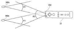
図9は、マーカ340mおよび340nと、コントローラ22との視野角を説明するための図である。図9に示すように、マーカ340mおよび340nは、それぞれ、視野角θ1の範囲で赤外光を放射する。また、撮像情報演算部80の撮像素子80cは、コントローラ22の視線方向を中心とした視野角θ2の範囲で入射する光を受光することができる。たとえば、マーカ340mおよび340nの視野角θ1は、共に34°(半値角)であり、一方、撮像素子80cの視野角θ2は41°である。プレイヤは、撮像素子80cが2つのマーカ340mおよび340nからの赤外光を受光することが可能な位置および向きとなるように、コントローラ22を把持する。具体的には、撮像素子80cの視野角θ2の中に少なくとも一方のマーカ340mおよび340nが存在し、かつ、マーカ340mまたは340nの少なくとも一方の視野角θ1の中にコントローラ22が存在する状態となるように、プレイヤはコントローラ22を把持する。この状態にあるとき、コントローラ22は、マーカ340mおよび340nの少なくとも一方を検知することができる。プレイヤは、この状態を満たす範囲でコントローラ22の位置および向きを変化させることによってゲーム操作を行うことができる。 FIG. 9 is a diagram for explaining viewing angles between the
なお、コントローラ22の位置および向きがこの範囲外となった場合、コントローラ22の位置および向きに基づいたゲーム操作を行うことができなくなる。以下では、上記範囲を「操作可能範囲」と呼ぶ。 In addition, when the position and orientation of the
操作可能範囲内でコントローラ22が把持される場合、撮像情報演算部80によって各マーカ340mおよび340nの画像が撮像される。すなわち、撮像素子80cによって得られる撮像画像には、撮像対象である各マーカ340mおよび340nの画像(対象画像)が含まれる。図10は、対象画像を含む撮像画像の一例を示す図である。対象画像を含む撮像画像の画像データを用いて、画像処理回路80dは、各マーカ340mおよび340nの撮像画像における位置を表す座標(マーカ座標)を算出する。 When the
撮像画像の画像データにおいて対象画像は高輝度部分として現れるため、画像処理回路80dは、まず、この高輝度部分を対象画像の候補として検出する。次に、画像処理回路80dは、検出された高輝度部分の大きさに基づいて、その高輝度部分が対象画像であるか否かを判定する。撮像画像には、対象画像である2つのマーカ340mおよび340nの画像340m’および340n’のみならず、窓からの太陽光や部屋の蛍光灯の光によって対象画像以外の画像が含まれていることがある。高輝度部分が対象画像であるか否かの判定処理は、対象画像であるマーカ340mおよび340nの画像340m’および340n’と、それ以外の画像とを区別し、対象画像を正確に検出するために実行される。具体的には、当該判定処理においては、検出された高輝度部分が、予め定められた所定範囲内の大きさであるか否かが判定される。そして、高輝度部分が所定範囲内の大きさである場合には、当該高輝度部分は対象画像を表すと判定される。逆に、高輝度部分が所定範囲内の大きさでない場合には、当該高輝度部分は対象画像以外の画像を表すと判定される。 Since the target image appears as a high luminance part in the image data of the captured image, the
さらに、上記の判定処理の結果、対象画像を表すと判定された高輝度部分について、画像処理回路80dは当該高輝度部分の位置を算出する。具体的には、当該高輝度部分の重心位置を算出する。ここでは、当該重心位置の座標をマーカ座標と呼ぶ。また、重心位置は撮像素子80cの解像度よりも詳細なスケールで算出することが可能である。ここでは、撮像素子80cによって撮像された撮像画像の解像度が126×96であるとし、重心位置は1024×768のスケールで算出されるものとする。つまり、マーカ座標は、(0,0)から(1024,768)までの整数値で表現される。 Further, as a result of the above determination processing, for the high luminance portion determined to represent the target image, the
なお、撮像画像における位置は、撮像画像の左上を原点とし、下向きをY軸正方向とし、右向きをX軸正方向とする座標系(XY座標系)で表現されるものとする。 The position in the captured image is represented by a coordinate system (XY coordinate system) in which the upper left of the captured image is the origin, the downward direction is the Y axis positive direction, and the right direction is the X axis positive direction.
また、対象画像が正しく検出される場合には、判定処理によって2つの高輝度部分が対象画像として判定されるので、2箇所のマーカ座標が算出される。画像処理回路80dは、算出された2箇所のマーカ座標を示すデータを出力する。出力されたマーカ座標のデータ(マーカ座標データ)は、上述したように、プロセッサ70によって入力データに含まれ、ゲーム装置12に送信される。 When the target image is correctly detected, two high-intensity parts are determined as the target image by the determination process, so that two marker coordinates are calculated. The
ゲーム装置12(CPU40)は、受信した入力データからマーカ座標データを検出すると、このマーカ座標データに基づいて、モニタ34の画面上におけるコントローラ22の指示位置(指示座標)と、コントローラ22からマーカ340mおよび340nまでの各距離とを算出することができる。具体的には、2つのマーカ座標の中点の位置から、コントローラ22の向いている位置すなわち指示位置が算出される。したがって、コントローラ22は、モニタ34の画面内の任意の位置を指示するポインティングデバイスとして機能する。また、撮像画像における対象画像間の距離が、コントローラ22と、マーカ340mおよび340nとの距離に応じて変化するので、2つのマーカ座標間の距離を算出することによって、ゲーム装置12はコントローラ22とマーカ340mおよび340nとの間の距離を把握できる。 When the game apparatus 12 (CPU 40) detects the marker coordinate data from the received input data, the game apparatus 12 (CPU 40) detects the indicated position (indicated coordinates) of the
このゲームシステム10では、荷重コントローラ36の上に足を乗せたり下ろしたりするようなプレイヤの動作によってゲームが行われる。この荷重コントローラ36に対するプレイヤの動作が、荷重コントローラ36で検出される荷重値に基づいて判別(識別)される。具体的には、プレイヤの体重値に対する荷重値の割合と重心位置とに基づいて、荷重コントローラ36に対してプレイヤが行った動作が判別される。より詳しくは、検出された荷重値の体重値に対する割合と重心位置とに基づいて、予め定められた(登録された)複数の動作のうちいずれの動作が行われたかを特定することが可能である。また、所定の動作が行われたか否かを、検出された荷重値の体重値に対する割合と重心位置とに基づいて判別することが可能である。 In this
この実施例では、踏み台昇降ゲームが行われる。踏み台昇降は、人が台の昇り降りを繰返し行う運動である。図11に示すように、荷重コントローラ36を踏み台に見立てて、プレイヤは荷重コントローラ36に昇って降りる動作を行って、このゲームをプレイする。 In this embodiment, a step up / down game is played. Step up / down is a movement in which a person repeatedly goes up and down. As shown in FIG. 11, the player performs the action of ascending and descending to the
なお、図11では、一例として、プレイヤの前に置かれた荷重コントローラ36に右足から昇り降りを行う場合が示されている。具体的には、1歩目(図11(A))で右足が乗せられ、2歩目(図11(B))でさらに左足が乗せられ、3歩目(図11(C))で右足が後ろに下ろされ、そして、4歩目(図11(D))で左足が後ろに下ろされる。 In FIG. 11, as an example, a case where the
なお、この荷重コントローラ36への昇り降り動作は、後述されるように、ゲーム画面の指示に従ったものであり、適宜変更可能である。したがって、図11では右足からの昇り降りであったが、左足からの昇り降りであってよい。また、図11では最初に乗せた足を先に下ろすが、後から乗せた足を先に下ろすようにしてもよい。また、図11ではプレイヤは前後に移動しつつ昇り降りをしているが、左右に移動しつつ昇り降りをしてもよいし、前後左右の移動を織り交ぜながら昇り降りをしてもよい。 The ascending / descending operation to the
また、腿上げ動作を組み込んだ踏み台昇降も行われ得る。図12には、図11の踏み台昇降に腿上げ動作を組み入れた場合のプレイヤの動作が示される。具体的には、1歩目(図12(A))では、図11の通常の踏み台昇降と同様に、右足が荷重コントローラ36に乗せられる。次に、2歩目(図12(B))で、左腿上げを行う。つまり、プレイヤは左足を持ち上げて荷重コントローラ36に乗る際に、左腿を振り上げて左膝を上げる。左足は荷重コントローラ36に着けられることがなく、プレイヤは右足のみで立つ状態になる。続いて、3歩目(図12(C))では、振り上げた左足が後ろに下ろされ、そして、4歩目(図12(D))で、右足が後ろに下ろされる。 In addition, the step up and down incorporating the thigh raising operation can also be performed. FIG. 12 shows the action of the player when the thigh raising action is incorporated in the step up / down of FIG. Specifically, in the first step (FIG. 12A), the right foot is placed on the
この実施例では、このような踏み台昇降の各動作、つまり、1歩目、2歩目、3歩目および4歩目の各動作を、荷重値に基づいて判別する。 In this embodiment, each operation of raising and lowering the step, that is, each operation of the first step, the second step, the third step, and the fourth step is determined based on the load value.
具体的には、発明者等は、荷重値のプレイヤの体重値に対する割合と荷重値の重心位置とを組み合わせて判断することにより、荷重コントローラ36に対するプレイヤの動作を判別できることを見出した。 Specifically, the inventors have found that the action of the player with respect to the
体重値は、プレイヤが静止状態で荷重コントローラ36の上に乗っているときに検出されるすべての荷重センサ36bの荷重値を合計することによって算出される。なお、体重値の測定の際には、たとえばプレイヤに荷重コントローラ36の上に両足で静かに乗るように指示する画面を表示する。荷重値の体重値に対する割合は、検出される全ての荷重センサ36bの荷重値の合計を体重値で割ることによって算出される。 The weight value is calculated by summing up the load values of all the
重心位置は、荷重コントローラ36の各荷重センサ36bの荷重値の重心位置である。この実施例では、荷重コントローラ36の矩形状の台36aの長辺がプレイヤの前後に、短辺がプレイヤの左右に位置するようにして、踏み台昇降が行われる。そして、動作の識別には、左右方向の重心位置が使用される。 The gravity center position is the gravity center position of the load value of each
プレイヤの左前の荷重センサ36bで検出される荷重値をa、左後の荷重センサ36bで検出される荷重値をb、右前の荷重センサ36bで検出される荷重値をc、右後の荷重センサ36bで検出される荷重値をdとしたとき、左右方向の重心位置XGは、次の数1によって算出される。
[数1]
XG=((c+d)−(a+b))*m
ここで、mは、定数であって、−1≦XG≦1となる値に設定される。The load value detected by the player's left
[Equation 1]
XG = ((c + d)-(a + b)) * m
Here, m is a constant and is set to a value satisfying −1 ≦ XG ≦ 1.
なお、この実施例では使用されないが、他の実施例では、動作によっては、前後方向の重心位置に基づいて識別が行われてよく、その場合、前後方向の重心位置YGは、次の数2によって算出できる。
[数2]
YG=((a+c)−(b+d))*n
ここで、nは定数であり、−1≦YG≦1となる値に設定される。Although not used in this embodiment, in other embodiments, depending on the operation, identification may be performed based on the center-of-gravity position in the front-rear direction. In this case, the center-of-gravity position YG in the front-rear direction is Can be calculated.
[Equation 2]
YG = ((a + c)-(b + d)) * n
Here, n is a constant and is set to a value satisfying −1 ≦ YG ≦ 1.
このように、左右方向の重心位置XGは、プレイヤの右側の荷重値(c+d)と左側の荷重値(a+b)との差分に基づいて算出され、前後方向の重心位置YGは、プレイヤの前側の荷重値(a+c)と下側の荷重値(b+d)との差分に基づいて算出される。 Thus, the center-of-gravity position XG in the left-right direction is calculated based on the difference between the load value (c + d) on the right side of the player and the load value (a + b) on the left side, and the center-of-gravity position YG in the front-rear direction is It is calculated based on the difference between the load value (a + c) and the lower load value (b + d).
なお、プレイヤから見て各荷重センサ36bがどの方向(この実施例では右前、右後、左前、左後)に存在しているかは、上述のように、予め決められまたはプレイヤによって設定されて記憶されている配置データから把握することができる。 Note that in which direction each
図13には、この実施例で判別される動作ごとの、体重値に対する荷重値の割合に関する条件と重心位置に関する条件とが示される。割合に関する条件と重心位置に関する条件とが所定の複数の動作の識別情報に対応付けられたテーブルが予め記憶される。 FIG. 13 shows a condition relating to the ratio of the load value to the body weight value and a condition relating to the position of the center of gravity for each operation discriminated in this embodiment. A table in which the condition relating to the ratio and the condition relating to the position of the center of gravity are associated with the identification information of a plurality of predetermined actions is stored in advance.
具体的には、右足乗せ動作は、図11(A)、図12(A)および図12(C)に示したように、右足を荷重コントローラ36に乗せ、左足を地面に下ろした状態にする動作である。荷重値の割合の条件は、25〜75%である。この動作では、片足が荷重コントローラ36上で、もう片足が地面にあるから、プレイヤの全体重の約半分が荷重コントローラ36にかかる。さらに、各動作の荷重値の割合の条件は、プレイヤ毎の癖等によって左右の足にかかる荷重のバランスの違い等を考慮して、決められている。 Specifically, as shown in FIGS. 11 (A), 12 (A), and 12 (C), the right foot is placed on the
また、重心位置の条件は、+0.01〜+1.0である。この実施例の踏み台昇降の際には、右足を荷重コントローラ36の台36aの中心よりも右側に、左足を台36aの中心よりも左側に置くことがプレイヤに要求されるので、各動作の重心位置の条件の値は、これを前提として設定されている。つまり、右足のみ荷重コントローラ36上に乗せられる場合、重心位置は荷重コントローラ36の右側に現れ、左足のみ乗せられる場合、重心位置は左側に現れ、両足が乗せられる場合、重心位置はほぼ中央に現れる。さらに、プレイヤ毎の癖等による重心位置の相違等を考慮して、各動作の重心位置の条件が決められている。 The condition of the center of gravity position is +0.01 to +1.0. When raising or lowering the footrest of this embodiment, the player is required to place the right foot on the right side of the center of the
両足乗せ動作は、図11(B)に示したように、両足とも荷重コントローラ36に乗せた状態にする動作である。割合の条件は95%以上(ほぼ全体重)であり、重心位置の条件は、−0.7〜+0.7である。 As shown in FIG. 11B, the both-leg-mounting operation is an operation for setting both feet on the
左足乗せ動作は、右足乗せ動作と逆であり、図11(C)に示したように、左足を荷重コントローラ36に乗せ、右足を地面に下ろした状態にする動作である。割合の条件は、25〜75%であり、重心位置の条件は、−1.0〜−0.01である。 The left foot ride operation is the reverse of the right foot ride operation, and as shown in FIG. 11C, the left foot is placed on the
左腿上げ動作は、図12(B)に示したように、右足を荷重コントローラ36に乗せ、左腿を上げた状態にする動作である。割合の条件は、100%以上であり、重心位置の条件は、+0.01〜+1.0である。荷重コントローラ36上で左腿を振り上げる際には、右足を踏み込むことになる。そのため、右足には全体重以上の荷重がかかり、単に静的に両足を乗せた場合よりも大きい荷重値、すなわち、体重値を超えるような荷重値が検出されることになる。したがって、単に片足や両足を乗せるだけの動作と腿上げ動作とを判別することができる。 As shown in FIG. 12B, the left thigh raising operation is an operation in which the right leg is placed on the
右腿上げ動作は、左腿上げ動作と逆であり、左足を荷重コントローラ36に乗せ、右腿を上げた状態にする動作である。割合の条件は、100%以上であり、重心位置の条件は、−1.0〜−0.01である。 The right thigh raising operation is the reverse of the left thigh raising operation, and is an operation in which the left foot is put on the
両足下ろし動作は、図11(D)および図12(D)に示したように、両足とも地面に下ろした状態にする動作である。割合の条件は、5%以下(ほぼゼロ)である。両足が荷重コントローラ36上にないので、荷重はほぼゼロとなる。したがって、重心位置は見ないようにする。 As shown in FIGS. 11 (D) and 12 (D), the both feet down operation is an operation in which both feet are lowered to the ground. The ratio condition is 5% or less (almost zero). Since both feet are not on the
荷重値の体重値に対する割合と重心位置とを算出して、この動作識別テーブルを参照することで、予め登録された複数の動作のうちのいずれの動作が行われたかが特定される。 By calculating the ratio of the load value to the weight value and the position of the center of gravity and referring to this action identification table, it is specified which of the plurality of actions registered in advance has been performed.
なお、図13に示す各条件の数値は一例であって適宜変更され得る。上述のように、荷重値の割合および重心位置には、プレイヤの癖等に応じた相違が現れる。したがって、実際の運動の前に、各動作の計測テスト等を行うことによって、プレイヤごとに条件値を調整するようにしてもよい。 In addition, the numerical value of each condition shown in FIG. 13 is an example, and can be changed suitably. As described above, a difference corresponding to the player's habit or the like appears in the ratio of the load value and the position of the center of gravity. Therefore, the condition value may be adjusted for each player by performing a measurement test or the like of each action before actual exercise.
図14にゲーム画面の一例を示す。画面の左右方向の中央には、プレイヤに対する動作指示のために複数のパネル400が表示されている。各パネル400には、この実施例の踏み台昇降の動作を構成する個々の動作が示されており、複数(この実施例では4つ)のパネル400が所定の順番で配列されることで、プレイヤが実行すべき一連の動作としての踏み台昇降の動作が指示されている。 FIG. 14 shows an example of the game screen. A plurality of
具体的には、各パネル400では、左右2つの足形が描かれており、足形の色、形状、模様等を変化させることによって、左右の足が行うべき乗り降り動作が表現される。なお、パネル400の基本の態様では、たとえば、地の色が白にされ、足形の線が灰色で描かれる。何の動作も実行する必要のない場合、この基本態様のパネル400が使用される。 Specifically, in each
図12では、4つのパネル400a−400dによって、図11の踏み台昇降の動作が指示されている。パネル400aは、図11(A)に示す1歩目の右足を乗せる動作を指示するパネルである。たとえば右の足形が赤色にされ、これにより、乗っていない状態から右足を乗せることが表現されている。パネル400bは、図11(B)に示す2歩目の左足を乗せる動作を指示するパネルである。たとえば左の足形が赤色に着色され、かつ、右の足形の赤色が薄くされている。これにより、右足を乗せた状態から左足をさらに乗せることが表現されている。パネル400cは、図11(C)に示す3歩目の右足を下ろす動作を指示するパネルである。たとえば左の足形の赤色が薄くされ、かつ、右の足形の上に赤色の下向き矢印が描かれている。これにより、両足を乗せた状態から右足を後方に下ろすことが表現されている。パネル400dは、図11(D)に示す4歩目の左足を下ろす動作を指示するパネルである。たとえば左の足形の上に赤色の下向き矢印が描かれている。これにより、左足を乗せた状態からその左足を後方に下ろすことが表現されている。 In FIG. 12, the operation of raising and lowering the step shown in FIG. 11 is instructed by the four
各パネル400は、順に画面上端から現れ画面下端に移動して消えるように構成されている。画面中央より下側の所定の位置には、枠402が固定的に配置されている。この枠402は、パネル400の移動経路上に設けられていて、枠402内で、パネル400の移動が一定時間停止されるようになっている。この枠402により、現在実行すべき動作のパネル400が指示される。つまり、画面上の複数のパネル400のうち、枠402の位置に移動して来たパネル400が現在実行すべき動作を示すことになる。 Each
さらに、画面には、たとえばパネル400の左右に、複数のキャラクタ404が表示されている。これらキャラクタ404は、パネル400および枠402による指示に合わせてその動作を行うように制御される。図12では、枠402内にパネル400aが移動しているので、各キャラクタ404は右足を台に乗せる動作を行っている。キャラクタ404の動きによって、パネル400で指示された動作を確認することができる。 Further, on the screen, for example, a plurality of
ゲーム装置12では、荷重コントローラ36で検出された荷重値から、体重値に対する割合と重心位置を算出し、上述の図13に示す動作識別条件テーブルに基づいて、登録された複数の動作のいずれの動作が行われたかを特定する。そして、特定された動作が、枠402によって指示された現在実行すべき動作かどうかが判定される。指示に従った動作が行われたと判断される場合には、プレイヤに得点が与えられる。 The
なお、腿上げ動作を組み込んだ踏み台昇降を指示する場合には、図15に示すようなパネル400が表示される。このパネル400では、図12に示す左腿上げ動作を組み込んだ踏み台昇降が指示されている。上述の通常の踏み台昇降の動作には赤色を使用するようにしたので、腿上げに関連する動作には、異なる色、たとえば緑色が使用される。具体的には、2歩目のパネル400bは、左足の腿上げを指示するものであり、たとえば左足形の色が緑色にされる。さらに、足が浮いていることを表現するために、左足形には影が付けられている。また、3歩目のパネル400cは、腿上げした左足を下ろす動作を指示するものであり、たとえば左足形の上に緑色の下向きの矢印が描かれる。なお、1歩目のパネル400aは、図14の通常の踏み台昇降の1歩目のパネル400aと同じであり、右足を乗せる動作を指示しており、右足形が赤色にされている。また、4歩目のパネル400dは、右足を下ろす動作を指示しており、右足形の上に赤色の下向き矢印が描かれる。 In addition, when instructing raising / lowering of the footrest incorporating the thigh raising operation, a
また、図14のゲーム画面では、図11の踏み台昇降を実行することをプレイヤに指示している。しかし、このゲーム装置12では、図13の動作識別条件テーブルに基づいて所定の複数の動作のうちいずれの動作が行われたかを特定することができる。したがって、画面上には、図11の通常の踏み台昇降を指示するためのパネル400(図14)と、図12の腿上げ動作を組み込んだ踏み台昇降を指示するためのパネル400(図15)の一方だけを表示して、当該表示された踏み台昇降のみをプレイヤに行わせるようにするだけでなく、たとえば、両方を同時に表示し、プレイヤにどちらか好きな方の踏み台昇降を行わせるようにすることも可能である。通常の踏み台昇降と腿上げ動作を組み込んだ踏み台昇降とでは、2歩目の動作と3歩目の動作がそれぞれ異なっているが、荷重コントローラ36の荷重値を検出し、当該検出された荷重値の体重値に対する割合と重心位置とを算出して、当該算出された割合と重心位置とに基づいて判別を行うことによって、2歩目の動作も3歩目の動作もそれぞれいずれの動作が行われたのかを特定することができる。この場合には、各動作をそれぞれ特定することができるので、それら特定された動作の履歴を記憶しておくことによって、プレイヤによって行われた一連の動作がどのような動作であったのかを特定することができる。たとえば、通常の踏み台昇降か腿上げ動作を組み込んだ踏み台昇降かを特定できるし、右足から始めた昇降か左足から始めた昇降かも特定できる。 On the game screen of FIG. 14, the player is instructed to perform the step up / down of FIG. However, in the
図13の動作識別条件テーブルに基づく動作の特定がより精度良く行われるようにするために、この実施例では、図14のような画面上の動作指示において、各動作を実行するのに適切なタイミングを示すようにしている。そして、そのタイミングに合わせて、荷重値を検出し、動作識別を行うようにしている。 In order to specify the operation based on the operation identification condition table of FIG. 13 with higher accuracy, in this embodiment, in the operation instruction on the screen as shown in FIG. 14, it is appropriate to execute each operation. The timing is shown. In accordance with the timing, the load value is detected and the operation is identified.
具体的には、図16に示すようなパネル400の移動の状態によって動作のタイミングが示される。上述のように、複数のパネル400は、所定の配列で画面上を上から下に移動し、かつ、枠402内で一定時間停止するように制御される。上側から移動してきたパネル400は枠402の上方で隣接した状態で一定時間停止し、それから枠402内へ移動を開始する。 Specifically, the operation timing is indicated by the movement state of the
そして、移動を開始してから所定時間PSが経過したときに、パネル400は枠402内に納まって停止し、その後、所定時間TAまで停止し続ける。所定時間TAが経過すると、パネル400は再び移動を開始し、この移動により当該パネル400が枠402外へ出るとともに、次のパネル400が枠402内へ入り始めることになる。 Then, when the predetermined time PS has elapsed since the start of the movement, the
このようにパネル移動に停止期間を設けることによって、各動作の指示の開始および終了をプレイヤに明確に示すことができる。パネル400の指示する動作は、当該パネル400が枠402内へ入り始めたときから当該パネル400が枠402内から出始めるときまでに実行されることが求められる。このように、動作判定には制限時間が設けられており、この制限時間は正否判定時間TAとして予め適宜な値に決められる。正否判定時間(制限時間)TAは、たとえば、足を乗せたり下ろしたりする動作をどのようなテンポでプレイヤに行わせるかに応じて適宜な値に設定される。 Thus, by providing the stop period for the panel movement, it is possible to clearly indicate to the player the start and end of each action instruction. The operation instructed by the
パネル停止時間PSは、たとえば足を乗せたり下ろしたりする動作に適切なタイミングとなるように、実験により予め適宜な値に決められる。たとえば、乗せたり下ろしたりするために動かした足が荷重コントローラ36または地面(床)にちょうど接触するようなタイミングや、腿上げのために足を振り上げ始めるようなタイミングを採用してよい。これにより、パネル400が移動している間に足を離して新たな場所に着け、パネル400が停止している間に足を完全に着けて当該動作を完了しつつ次に移行するために体勢を整えるような動きや、パネル400が移動している間に体を荷重コントローラ36の方へ移動しつつ腿を振り上げる体勢を整え、パネルが停止している間に腿上げ動作を完了するような動き等を、パネル400の移動状態に合わせて行うことが可能になる。 The panel stop time PS is determined in advance to an appropriate value by experiment so as to be at an appropriate timing for, for example, the operation of putting on and down the foot. For example, it is possible to employ a timing at which the foot that has been moved to get on or down just touches the
そして、動作の識別を、動作の指示が開始されてから一定時間すなわちパネル停止時間PSが経過してから行う。このようにすれば、プレイヤが当該動作を完了した状態の荷重値を検出し、当該適切な荷重値に基づいて動作識別を行うことができるので、識別の精度をより良くすることができる。 Then, the operation is identified after a predetermined time, that is, the panel stop time PS has elapsed since the operation instruction was started. In this way, it is possible to detect the load value in a state in which the player has completed the motion and perform motion identification based on the appropriate load value, so that the accuracy of identification can be improved.
なお、制限時間TAが経過するまでに、動作が特定できなかった場合や、特定された動作が指示動作ではなかった場合等には、指示動作の実行に失敗したことが判定される。失敗判定の場合、プレイヤには得点が与えられない。 If the operation cannot be specified before the time limit TA elapses, or if the specified operation is not an instruction operation, it is determined that the instruction operation has failed. In the case of failure determination, no score is given to the player.
一方、制限時間TAが経過するまでに指示動作が行われたことが判別されれば、当該指示動作の実行に成功したことが判定されて、得点が与えられる。 On the other hand, if it is determined that the instruction operation has been performed before the time limit TA has elapsed, it is determined that the instruction operation has been successfully executed, and a score is given.
図17にはゲーム装置12のメモリマップの一例が示される。メモリマップはプログラム記憶領域500およびデータ記憶領域502を含む。プログラムとデータは、光ディスク18から一度に全部または必要に応じて部分的に、かつ順次的に読み出され、外部メインメモリ46または内部メインメモリ42eに記憶される。また、データ記憶領域502には、処理によって生成または取得されたデータも記憶される。プログラムは、このゲームシステム10を荷重検出装置として機能させるための荷重検出プログラムである。 FIG. 17 shows an example of a memory map of the
なお、図17にはメモリマップの一部のみが示されており、処理に必要な他のプログラムおよびデータも記憶される。たとえば、音声、効果音、音楽などの音を出力するためのサウンドデータ、画面を生成するための画像データ、音出力プログラム、画像生成表示プログラムなどが、光ディスク18から読み出されてデータ記憶領域502またはプログラム記憶領域500に記憶される。なお、本実施例においては、プログラムとデータは光ディスク18から読み出されるが、別の実施例においては、たとえばゲーム装置12に内蔵されるフラッシュメモリ44等の不揮発的な記憶媒体に予め記憶したプログラムやデータを読み出して、外部メインメモリ46または内部メインメモリ42eに記憶するようにしてもよい。その際さらに、ゲーム装置12の無線通信モジュール50または拡張コネクタ60に接続される通信モジュール等を用いて、ネットワーク経由でダウンロードしたプログラム等を当該記憶媒体に記憶しておくようにしてもよい。 FIG. 17 shows only a part of the memory map, and other programs and data necessary for processing are also stored. For example, sound data for outputting sound such as sound, sound effects, music, image data for generating a screen, sound output program, image generation display program, and the like are read from the
記憶領域504には荷重値検出プログラムが記憶される。このプログラムは、荷重コントローラ36の荷重値を検出するためのものである。たとえば、荷重が必要なときに荷重取得命令が無線コントローラモジュール52を介して荷重コントローラ36に送信され、これに応じて無線コントローラモジュール52で受信された荷重コントローラ36のデータから、各荷重センサ36bの荷重値が検出される。動作判別を行う際には、たとえば1フレーム(1/60秒)の一定時間ごとに荷重値が取得される。 The
記憶領域506には動作指示プログラムが記憶される。このプログラムは、プレイヤに実行すべき動作を指示するためのものである。一連の動作を指示するための複数のパネル400の移動および停止が、上述のように、制限時間TAおよびパネル停止時間PS等に基づいて制御される。 An operation instruction program is stored in the
記憶領域508には経過時間計測プログラムが記憶される。このプログラムは、動作の指示があってから経過した時間を計測するためのものである。具体的には、パネル400が枠402の上方で隣接する位置から枠402内への移動を開始したときが、当該パネル400に対応する動作が指示されたときであるから、パネル400の枠402内への移動を開始したときから時間がカウントされる。 The
記憶領域510には荷重割合算出プログラムが記憶される。このプログラムは、検出された荷重値の体重値に対する割合を算出するためのものである。各荷重センサ36bの荷重値を合計し、当該合計値を体重値で割ることによって、この割合が算出される。 The
記憶領域512には重心位置算出プログラムが記憶される。このプログラムは、検出された荷重値の重心位置を算出するためのものである。重心位置は、上述の数1または数2に従って算出される。 The
記憶領域514には動作判別プログラムが記憶される。このプログラムは、算出された荷重値の割合および重心位置ならびに動作識別テーブルに基づいて、所定の複数の動作のうちのいずれの動作が行われたかを特定するためのものである。 The
データ記憶領域502の記憶領域516はプレイヤの体重値が記憶される。体重値は、プレイヤが静止状態で荷重コントローラ36の上に乗っているときに検出されるすべての荷重センサ36bの荷重値を合計することによって算出される。なお、体重値の測定の際には、プレイヤに荷重コントローラ36の上に両足で静かに乗るように指示する画面を表示してよい。 A
記憶領域518には時間カウンタが記憶される。時間カウンタは、各動作の指示が行われてからの経過時間を計測するためのカウンタであり、この実施例では一定時間(1フレーム)ごとにカウントが行われる。 The
記憶領域520には、経過時間計測プログラムによって計測された経過時間が記憶される。時間カウンタの値に基づいて、踏み台昇降の各動作の指示があったときからの経過時間が算出されて記憶される。 The
記憶領域522には荷重検出プログラムによって検出された各荷重センサ36bの荷重値が記憶される。 The
記憶領域524には荷重割合算出プログラムによって算出された荷重値の体重値に対する割合が記憶される。記憶領域526には重心位置算出プログラムによって算出された重心位置が記憶される。 The
記憶領域528には光ディスク18等から読み出された動作識別条件テーブルが記憶される。動作識別条件テーブルには、図13に示したように、所定の複数の動作を判別するための条件が記憶されている。具体的には、荷重値の体重値に対する割合に関する条件と、重心位置に関する条件とが、各動作の識別情報に対応付けられている。動作判別の際には、このテーブルを参照して、割合と重心位置の両条件を満足する動作を検出することによって、プレイヤによって行われた動作が特定される。 The
記憶領域530には、動作判別プログラムによって特定された動作の識別情報が記憶される。なお、動作を特定することができなかった場合には、特定不可を示すデータが記憶される。 The
記憶領域532には、指示パネル400が停止する時間を示すパネル停止時間PSが記憶される。記憶領域534には、現在実行すべき動作の判定の制限時間TAが記憶される。パネル停止時間PSおよび制限時間TAは光ディスク18から読み出される。 The
記憶領域536には、ゲーム結果が記憶される。ゲーム結果としては、プレイヤの得点、各動作の評価(OKまたは失敗)などが記憶される。 The
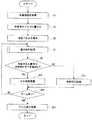
図18には、踏み台昇降を行う際のゲーム装置12の動作の一例が示される。ステップS1では、CPU40は体重値測定処理を実行する。プレイヤが静止状態で荷重コントローラ36に乗ったときの各荷重センサ36bの荷重値を検出する。具体的には、CPU40は、荷重取得命令を無線コントローラモジュール52等を介して荷重コントローラ36に送信する。これに応じて、荷重コントローラ36のマイコン100は各荷重センサ36bの荷重値を検出し、各荷重値を含む入力データを無線モジュール106等を介してゲーム装置12に送信する。CPU40は、無線コントローラモジュール52等を介して各荷重値を含む入力データを受信し、各荷重値を検出して記憶領域522に記憶する。そして、すべての荷重センサ36bの荷重値を合計することによって体重値を算出する。なお、モニタ34には、プレイヤに対して荷重コントローラ36上に両足で乗るように指示する画面を表示してよい。 FIG. 18 shows an example of the operation of the
続くステップS3で、CPU40は、体重値を外部メインメモリ46に書き込む。これによって記憶領域516にプレイヤの体重値が記憶される。 In subsequent step S <b> 3, the
そして、ステップS5で、CPU40は指示パネル400を表示する。具体的には、CPU40は、システムLSI42のGPU42b等を用いて、指示パネル400を含む図14に示すようなゲーム画面を生成してモニタ34に表示する。なお、上述のように、踏み台昇降の各動作を指示する各パネル400は、所定の順番で画面中央の上端の所定の初期位置に表示されて、下方の枠402に向けて一定の停止時間を挟みながら移動される。各パネル400の動作が現在実行すべき動作となってからの移動の制御は、動作判別処理で開始されるので、このステップS5では、最初の指示パネル400が枠402の上側で隣接して停止するまで処理が行われる。 In step S5, the
続いて、ステップS7で、CPU40は、動作判別処理を実行する。この動作判別処理により、プレイヤが荷重コントローラ36に対して行った動作が特定される。動作判別処理におけるCPU40の動作の一例が図19に示される。 Subsequently, in step S7, the
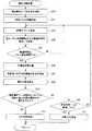
動作判別処理を開始すると、ステップS31で、CPU40は、動作指示プログラムに従って指示パネル400の移動処理を開始する。このステップS31で開始されるパネル400の移動処理は、図19の他の処理と並列的に実行される。このパネル400の移動処理によって、現在実行すべき動作を指示するパネル400が枠402の上方の隣接位置から枠402内に移動される。なお、移動処理を開始するときに枠402の上方の隣接位置に存在しているパネル400に対応する動作が現在実行すべき動作である。この図19では省略しているが、たとえば移動処理を開始する前に、枠402の上方の隣接位置に存在するパネル400が、予め記憶された当該隣接位置の座標データと各パネル400の現在の位置を示す座標データを照合することによって検出され、当該検出されたパネル400に対応する動作の識別情報が、現在実行すべき動作の識別情報として検出されて記憶される。また、移動処理では、図16に示したように、現在実行すべき動作に対応するパネル400は、移動を開始してから所定時間PSが経過したときに枠402内に納まって停止し、移動を開始してから所定時間TAが経過するときまで枠402内で停止し続けるように制御される。 When the operation determination process is started, in step S31, the
続くステップS33−S49の処理は、ステップS47で動作が特定されたと判断されるまで、またはステップS49で動作が制限時間内に行われなかったと判断されるまで、一定時間(1フレーム)ごとに実行される。 The processes in subsequent steps S33 to S49 are executed at regular time intervals (one frame) until it is determined in step S47 that the operation has been specified or until it is determined in step S49 that the operation has not been performed within the time limit. Is done.
ステップS33では、CPU40は時間カウント処理を実行する。たとえば、時間カウンタをインクリメントすることによって、記憶領域518の時間カウンタの値を更新する。この時間カウント処理によって、動作指示が行われたときからの経過時間を計測することが可能になる。 In step S33, the
続くステップS35で、CPU40は、指示パネル400の移動開始からの経過時間を、記憶領域518の時間カウンタの値に基づいて検出して記憶領域520に記憶する。 In subsequent step S <b> 35,
そして、ステップS37で、CPU40は、経過時間がパネル停止時間PS以上になったか否かを判断する。すなわち、足を台に乗せたり下ろしたりするような動作に適切なタイミングに設定されているパネル停止時間PSを用いて、動作の判別に適切なタイミングになったかどうかを判断する。これにより、たとえば動作の完了前の状態で検出された荷重値を元に動作の判別が行われてしまうことを回避し、識別精度をよりよくすることができる。ステップS37で“NO”の場合には、動作の判別タイミングに到達していないので、処理はステップS33に戻る。 In step S37, the
一方、ステップS37で“YES”の場合、つまり、動作の判別タイミングになったと判断される場合には、CPU40は、ステップS39で荷重値取得処理を実行する。具体的には、CPU40は、無線コントローラモジュール52等を介して荷重取得命令を荷重コントローラ36に送信する。これに応じて、検出された荷重値を含む入力データが荷重コントローラ36から送信されるので、無線コントローラモジュール52で受信した入力データから各荷重センサ36bの荷重値を検出して記憶領域522に記憶する。 On the other hand, if “YES” in the step S37, that is, if it is determined that the operation determination timing has come, the
続くステップS41で、CPU40は、検出された荷重値の体重値に対する割合を算出する。具体的には、各荷重センサ36bの荷重値を合計し、当該合計値の体重値に対する割合を算出して、記憶領域524に記憶する。 In subsequent step S41, the
また、ステップS43で、CPU40は、重心位置を算出する。具体的には、検出された各荷重センサ36bの荷重値に基づいて、上述の数1に従って重心位置を算出し、記憶領域526に記憶する。 In step S43, the
そして、ステップS45で、CPU40は、記憶領域528の動作識別条件テーブルに基づいて、割合と重心位置の両条件を満足する動作を特定する。具体的には、記憶領域524の割合が動作識別条件テーブルの割合の条件を満足する動作を検出するとともに、記憶領域526の重心位置が動作識別条件テーブルの重心位置の条件を満足する動作を検出する。そして、両方の条件で検出された動作を検出する。なお、動作識別条件テーブルに登録されたすべての動作を対象として、特定処理を行ってもよいし、動作識別条件テーブルに登録された動作のうち、画面上に表示されている複数のパネル400の動作を対象として、特定処理を行ってもよい。 In step S45, the
続いて、ステップS47で、CPU40は、動作が特定されたか否かを判断する。ステップS47で“NO”の場合、つまり、割合と重心位置の両条件ともに満足された動作が存在しない場合には、ステップS49で、CPU40は、記憶領域520の経過時間を参照して、所定時間TAが経過したか否かを判断する。ステップS49で“NO”の場合には、つまり、経過時間が制限時間TA内である場合には、処理はステップS33に戻る。 Subsequently, in step S47, the
一方、ステップS47で“YES”の場合、つまり、割合と重心位置の両条件とも満足する動作が検出された場合には、CPU40は、ステップS51で、特定された動作の識別情報を記憶領域530に記憶する。 On the other hand, if “YES” in the step S47, that is, if an operation that satisfies both the ratio and the gravity center position is detected, the
また、ステップS49で“YES”の場合、つまり、制限時間TAを経過しても動作を特定することができなかった場合には、CPU40はステップS53で特定不可を示すデータを記憶領域530に記憶する。ステップS51またはステップS53を終了すると、この動作判別処理を終了して、処理は図18のステップS9へ戻る。 If “YES” in the step S49, that is, if the operation cannot be specified even after the time limit TA has elapsed, the
図18のステップS9では、CPU40は、特定された動作が、現在実行すべき動作であるか否かを判断する。現在実行すべき動作は、枠402内に存在するパネル400で指示される動作であり、図19のステップS31で開始されて並列的に実行されているパネル400の移動処理において特定され得る。 In step S9 in FIG. 18, the
ステップS9で“YES”の場合、つまり、プレイヤが指示通りの動作を行った場合には、CPU40は、ステップS11でOK判定処理を実行する。具体的には、プレイヤに所定の点数が与えられ、ゲーム結果記憶領域536のプレイヤの得点データに加算される。また、現在実行すべき動作についてOK判定を示す評価データも記憶領域536に記憶される。また、OKの文字等によって動作がOKであったことを画面上に表示するようにしてもよい。さらに、所定の音をスピーカ34aから出力して、指示に従った正解の動作であったことを報知するようにしてもよい。 If “YES” in the step S9, that is, if the player performs an operation as instructed, the
一方、ステップS9で“NO”の場合、つまり、現在実行すべき動作とは異なる動作が特定された場合や特定不可であった場合には、CPU40は、ステップS13で失敗判定処理を実行する。具体的には、プレイヤに得点が与えられない。また、現在実行すべき動作について失敗判定を示す評価データがゲーム結果記憶領域536に記憶される。また、失敗の文字等によって動作に失敗したことを画面上に表示するようにしてもよい。 On the other hand, if “NO” in the step S9, that is, if an operation different from the operation to be executed is specified or cannot be specified, the
続くステップS15で、CPU40は、ゲーム終了であるか否かを判断する。たとえば、踏み台昇降を所定の時間または所定の回数行ったかどうかを判断する。あるいは、指示された動作の実行に失敗したかどうかを判断する。 In subsequent step S15, the
ステップS15で“NO”の場合、処理はステップS7に戻って、踏み台昇降の次の動作に関して、動作判別処理を行う。なお、上述の図16に示したように、指示パネル400は枠402内への移動を開始してから所定時間PSが経過したときに停止し、さらに所定時間TAが経過したときに、当該指示パネル400は枠402外に移動を開始する。これと同時に、次の動作の指示パネル400が枠402内へ移動を開始することとなる。つまり、前のパネル400の移動開始から所定時間TAが経過したときに、次のパネル400の移動が開始されてプレイヤに当該動作が指示される。したがって、動作判別処理の実行は、前の指示パネル400の移動開始から所定時間TAが経過するまで待機される。 If “NO” in the step S15, the process returns to the step S7, and the operation determination process is performed with respect to the next operation of the step up / down. Note that, as shown in FIG. 16 described above, the
一方、ステップS15でゲーム終了条件が満足されたと判断される場合には、ステップS17で、CPU40はゲーム終了処理を実行して、踏み台昇降のゲーム処理を終了する。たとえば、踏み台昇降の各動作の成功により獲得された得点の合計を計算したり、当該得点や得点に応じた評価結果等を画面に表示したりする。 On the other hand, when it is determined in step S15 that the game end condition is satisfied, in step S17, the
この実施例によれば、荷重コントローラ36で検出される荷重値の体重値に対する割合と重心位置とに基づいて、予め定められた複数の動作のうちのいずれの動作が行われたかを特定するようにしたので、荷重コントローラ36に対するプレイヤの動作を判別することができる。 According to this embodiment, based on the ratio of the load value to the weight value detected by the
なお、上述の実施例では、動作の指示が行われてからの経過時間が所定の時間(パネル停止時間PS)以上になった後に荷重値を検出し、当該適切なタイミングで検出された荷重値に基づいて精度良く動作を判別するようにしていた。しかし、他の実施例では、ステップS37の処理を行わないようにして、動作の指示が行われてから所定時間(たとえば制限時間TA)が経過するまで単位時間(例えば、1フレーム)毎に荷重値を検出し、単位時間毎に、検出された荷重値に基づいて動作を判別するようにしてもよい。たとえば1フレーム毎の検出を行う場合には、各動作を完了していないときの荷重値も検出されることとなるが、動作ごとの識別条件をそれぞれ重複しないように規定しておくことによって、正確に動作を特定することができる。また、検出毎の判別ではなく、所定時間にわたって検出される複数の荷重値に基づいて判別を行うようにしてもよく、その場合、複数の荷重値を総合的に判別することによって判別の精度を確保することが可能である。 In the above-described embodiment, the load value is detected after the elapsed time after the operation instruction has been performed exceeds the predetermined time (panel stop time PS), and the load value detected at the appropriate timing is detected. The operation is discriminated accurately based on the above. However, in another embodiment, the process of step S37 is not performed, and the load is applied every unit time (for example, one frame) until a predetermined time (for example, the time limit TA) elapses after the operation instruction is performed. The value may be detected, and the operation may be discriminated based on the detected load value every unit time. For example, when performing detection for each frame, the load value when each operation is not completed is also detected, but by specifying the identification conditions for each operation so as not to overlap, The operation can be specified accurately. In addition, the determination may be performed based on a plurality of load values detected over a predetermined time instead of the detection for each detection. In this case, the determination accuracy is improved by comprehensively determining the plurality of load values. It is possible to secure.
また、上述の各実施例では、荷重値の体重値に対する割合と重心位置の両条件を満足する動作を特定し、当該動作が現在実行すべき動作(指示された動作)であると判断される場合に、OK判定をするようにしたが、他の実施例では、過去の動作がOK判定されたかどうか、つまり、プレイヤが過去の動作を適切に行っていたかどうかをさらに判断するようにしてもよい。この場合には、プレイヤによる過去の動作の実行の適否に応じて、現在の動作の実行の適否を判断することができる。たとえば過去の動作の実行の成功が必要とされる動作等の判別を適切に行うことができる。 Further, in each of the above-described embodiments, an operation that satisfies both the ratio of the load value to the body weight value and the center of gravity position is specified, and it is determined that the operation is an operation to be currently executed (instructed operation). In this case, the OK determination is made. However, in another embodiment, it may be further determined whether or not the past action is OK, that is, whether or not the player has appropriately performed the past action. Good. In this case, it is possible to determine whether or not the current action is to be executed according to whether or not the player has executed the past action. For example, it is possible to appropriately determine an operation that requires a successful execution of a past operation.
具体的には、ステップS9で“YES”の場合に、過去の動作についてのゲーム結果データを参照して、OK判定を示す評価データが記憶されているか否かを判断するようにしてよく、この判断で“YES”の場合にステップS11のOK判定処理を行い、“NO”の場合にステップS13の失敗判定処理を行う。たとえば、過去3回の動作のうちで少なくとも1回以上OK判定がなされていれば、現在の動作についてOK判定を行い、1回もOK判定がなされていなければ失敗判定をするようにしてもよい。上述の踏み台昇降のような一連の動作を構成する動作の場合には、たとえば過去の少なくとも1つの動作、所定の動作、またはすべての動作等についてOK判定が行われていることが条件とされてよい。具体的には、上述の踏み台昇降の場合、4歩目の両足を下ろす動作については、1〜3歩目のいずれかの動作がOK判定されたことを、OK判定の条件としてもよい。 Specifically, if “YES” in the step S9, it is possible to determine whether or not evaluation data indicating an OK determination is stored with reference to the game result data regarding the past action. If “YES” in the determination, an OK determination process in step S11 is performed, and if “NO”, a failure determination process in step S13 is performed. For example, if the OK determination has been made at least once among the past three operations, the OK determination is made for the current operation, and if the OK determination has not been made once, the failure determination may be made. . In the case of an operation that constitutes a series of operations such as stepping up and down as described above, for example, it is a condition that an OK determination is made for at least one past operation, a predetermined operation, or all operations. Good. Specifically, in the case of the above-described step up / down movement, regarding the operation of lowering both feet in the fourth step, it may be determined that one of the first to third steps is OK.
また、上述の各実施例では、荷重値の体重値に対する割合および重心位置に基づく動作判別の実施例として、予め定められた複数の動作のうちのいずれの動作が実行されたかを、荷重値の体重値に対する割合と重心位置とに基づいて特定するようにしていた。しかし、他の実施例では、所定の動作が行われたかどうかを、荷重値の体重値と重心位置とに基づいて判別するようにしてもよい。たとえば、上述の各実施例では、図14に示したように現在実行すべき動作の適切なタイミングを示すためにパネル400および枠402を画面上に表示し、パネル400の移動および停止を制御するようにしているので、枠402で指示されたパネル400に対応する動作について、荷重値の体重値に対する割合と重心位置の両条件が満足されたか否かを判定するようにしてよい。これによって、当該指示された動作がプレイヤによって実行されたか否かを判別することができる。 Further, in each of the above-described embodiments, as an example of the operation determination based on the ratio of the load value to the body weight value and the position of the center of gravity, which of the plurality of predetermined operations is executed is The identification is based on the ratio to the weight value and the position of the center of gravity. However, in another embodiment, whether or not a predetermined operation has been performed may be determined based on the weight value of the load value and the position of the center of gravity. For example, in each of the above-described embodiments, as shown in FIG. 14, the
この実施例の場合のゲーム装置12のCPU40の動作の一例が図20に示される。図20と上述の図18との相違点は、ステップS9−S13が削除された点と、ステップS7の動作判別処理における動作が変更されている点である。図20のステップS101の変更された動作判別処理の詳細は図21に示される。なお、図18のステップS11とS13の各判定処理は、ステップS101の動作判別処理内に組み入れられている。図20および図21では、図18の処理と同様の処理には同一の参照符号を付しており、ここではそれらの詳細な説明を省略する。 An example of the operation of the
図21の動作判別処理を開始すると、ステップS111で、CPU40は、現在実行すべき動作を特定する。枠402の上方の隣接位置に存在しているパネル400に対応する動作が現在実行すべき動作である。たとえば、上述のように、枠402の上方の隣接位置に存在するパネル400が、予め記憶された当該隣接位置の座標データと各パネル400の現在の位置を示す座標データを照合することによって検出され、当該検出されたパネル400に対応する動作の識別情報が、現在実行すべき動作の識別情報として検出されて記憶される。なお、ステップS31で開始される移動処理では、上述のように、現在実行すべき動作を指示するパネル400を含む複数のパネル400の移動が制御される。現在実行すべき動作を指示するパネル400については、当該パネル400は枠402内へ移動を開始し、移動開始から所定時間PSが経過したときに枠402内に納まって停止し、移動開始してから所定時間TAが経過するときまで枠402内で停止し続けるように制御される。 When the operation determination process of FIG. 21 is started, in step S111, the
ステップS41で荷重値の体重値に対する割合を算出してステップS43で重心位置を算出した後、CPU40は、ステップS113で、現在実行すべき動作についての割合と重心位置の両条件が満足されたか否かを判断する。具体的には、現在実行すべき動作の識別情報はステップS111で検出されているので、当該識別情報に対応する割合の条件と重心の条件とを動作識別条件テーブルから読み出す。そして、ステップS41で算出された割合が、読み出した割合の条件を満足し、かつ、ステップS43で算出された重心位置が、読み出した重心位置の条件を満足するかを判断する。 After calculating the ratio of the load value to the weight value in step S41 and calculating the center of gravity position in step S43, the
ステップS113で“YES”の場合、つまり、現在実行すべき動作がプレイヤによって実行されたと判別された場合には、CPU40は、ステップS11でOK判定処理を実行する。なお、このOK判定処理は図18のステップS11と同様である。 If “YES” in the step S113, that is, if it is determined that the action to be currently executed is executed by the player, the
一方、ステップS113で“NO”の場合、つまり、現在実行すべき動作がプレイヤによって実行されたとは判別できない場合には、CPU40はステップS49でステップS31における移動開始から所定時間TAが経過したか否かを判断する。ステップS49で“YES”の場合、つまり、制限時間TAを経過しても現在実行すべき動作がプレイヤによって実行されなかった場合には、CPU40は、ステップS13で失敗判定処理を実行する。なお、この失敗判定処理は図18のステップS13と同様である。ステップS11またはS13を終了すると、この図21の動作判別処理を終了して、処理は図20のステップS15に戻る。 On the other hand, if “NO” in the step S113, that is, if it cannot be determined that the action to be currently executed is executed by the player, the
なお、この図20および図21の実施例においても、上述のように、動作の指示が行われてから所定時間(たとえば制限時間TA)が経過するまで単位時間(例えば、1フレーム)毎に荷重値を検出し、単位時間毎に、検出された荷重値に基づいて動作を判別するようにしてもよい。この場合、上述の図18および図19の実施例と異なり、所定の動作(指示された動作)が行われたかどうかを判別するので、動作ごとの識別条件には、他の動作の条件との重複を許容することが可能になり、たとえば個人の癖等を考慮して条件を広く設定することが可能である。 20 and FIG. 21 as well, as described above, the load is applied every unit time (for example, one frame) until a predetermined time (for example, the time limit TA) elapses after the operation is instructed. The value may be detected, and the operation may be discriminated based on the detected load value every unit time. In this case, unlike the embodiments of FIGS. 18 and 19 described above, it is determined whether or not a predetermined operation (instructed operation) has been performed. Therefore, the identification condition for each operation includes the conditions of other operations. It is possible to allow duplication, and it is possible to set a wide range of conditions in consideration of personal habits, for example.
さらに、この図20および図21の実施例においても、上述のように、割合と重心位置の両条件のほかに、過去の動作がOK判定されたかどうか、つまり、プレイヤが過去の動作を適切に行っていたかどうかをさらに判断するようにしてもよい。具体的には、ステップS113で“YES”の場合に、過去の動作についてのゲーム結果データを参照して、OK判定を示す評価データが記憶されているか否かを判断するようにしてよく、この判断で“YES”の場合にステップS11のOK判定処理を行い、“NO”の場合にステップS13の失敗判定処理を行う。判定対象の動作や必要なOK判定の数等の条件は、上述のように、適宜に設定され得る。たとえば、踏み台昇降の4歩目の動作については、4歩目の動作の判定タイミングでは、割合の条件に基づいて両足が下ろされた状態であることを判別するようにしている。したがって、過去の1−3歩目の動作の実行の適否をさらに判断することによって、プレイヤが一度も荷重コントローラ36に乗っていなかったにも関わらず得点が与えられてしまうのを防止することができる。 Further, in the embodiment of FIGS. 20 and 21 as well, as described above, in addition to the ratio and the center of gravity position, whether or not the past motion is determined to be OK, that is, the player appropriately determines the past motion. You may make it further judge whether it was going. Specifically, if “YES” in the step S113, it is possible to determine whether or not evaluation data indicating an OK determination is stored with reference to the game result data regarding the past action. If “YES” in the determination, an OK determination process in step S11 is performed, and if “NO”, a failure determination process in step S13 is performed. Conditions such as the operation of the determination target and the number of necessary OK determinations can be appropriately set as described above. For example, with respect to the fourth step of stepping up and down, it is determined at the determination timing of the fourth step that the both feet are in a lowered state based on the ratio condition. Therefore, it is possible to prevent the player from being awarded a score even though the player has never been on the
10 …ゲームシステム(荷重検出装置)
12 …ゲーム装置
18 …光ディスク
22 …コントローラ
34 …モニタ
34a …スピーカ
36 …荷重コントローラ
36b …ロードセル(荷重センサ)
40 …CPU
42 …システムLSI
42a …入出力プロセッサ
42b …GPU
42c …DSP
42d …VRAM
42e …内部メインメモリ
44 …フラッシュメモリ
46 …外部メインメモリ
48 …ROM/RTC
52 …無線コントローラモジュール
54 …ディスクドライブ
56 …AV IC
58 …AVコネクタ
60 …拡張コネクタ
100 …マイコン
102 …ADコンバータ
104 …DC−DCコンバータ
106 …無線モジュール
108 …増幅器
400 …パネル
402 …枠10 ... Game system (load detection device)
DESCRIPTION OF
40 ... CPU
42 ... System LSI
42a: I /
42c: DSP
42d ... VRAM
42e ... Internal
52 ...
58 ...
Claims (8)
Translated fromJapanese前記荷重センサによって測定される前記支持台にかかる荷重値を取得する荷重値取得ステップ、
前記荷重値取得ステップによって取得された前記荷重値の前記プレイヤの体重値に対する割合を算出する割合算出ステップ、
前記荷重値取得ステップによって取得された前記荷重値の重心位置を算出する重心位置算出ステップ、および
前記割合と前記重心位置の組み合わせに基づいて、前記支持台に対して前記プレイヤが行った動作を判別する動作判別ステップを前記コンピュータに実行させる、プログラム。AHelp program is executed in a computerto obtain a load value outputted from the loadcontroller comprising a support base leg of the player has two or more load sensors spaced is placed,
A load valueacquisition step ofacquiring a load value applied to the support base measured by the load sensor;
Ratio calculating step of calculating the ratio of the weight value of the player of the load valueacquired by the loadvalue acquiring step,
Center-of-gravity position calculation step of calculating the center of gravity of the load valueacquired by the loadvalue acquiring step, and on the basis of thecombination of the positionof the centerof gravity and the ratio, determined action the player performs with respect to the support base the operation determination step of causing the computer toperform, program.
前記指示ステップで指示が行われてからの経過時間を計測する経過時間計測ステップを前記コンピュータにさらに実行させ、
前記動作判別ステップは、前記経過時間が所定時間内にある間、前記指示ステップで指示された動作が行われたか否か判別する、請求項2記載のプログラム。An instruction step for instructing the player to perform any one of a plurality of movements as the predetermined action, and an elapsed time measurement step for measuring an elapsed time since the instruction is given in the instruction step. Further causing the computer to execute,
The operation determining step, while the elapsed time is within a predetermined time, the operation instructed by the instruction step determines whether or not made, theprogram of claim 2 wherein.
前記荷重センサによって測定される前記支持台にかかる荷重値を取得する荷重値取得手段、
前記荷重値取得手段によって取得された前記荷重値の前記プレイヤの体重値に対する割合を算出する割合算出手段、
前記荷重値取得手段によって取得された前記荷重値の重心位置を算出する重心位置算出手段、および
前記割合と前記重心位置の組み合わせに基づいて、前記支持台に対して前記プレイヤが行った動作を判別する動作判別手段を備える、情報処理装置。An information processing apparatusfor obtaining a load value output from a load controller having two or more load sensors spaced apart and having a support base on which a player's foot is placed,
Load valueacquisition means foracquiring a load value applied to the support base measured by the load sensor;
Ratio calculation means for calculating the ratio of the weight value of the player of the load valueacquired by the loadvalue acquiring means,
Gravity position calculating means for calculating a barycentric position of the load valueacquired by the loadvalue acquiring means, and based ona combination of the gravity center position and the ratio, determined action the player performs with respect to the support base Aninformation processing apparatus comprising operation determining means.
前記荷重センサによって測定される前記支持台にかかる荷重値を取得する荷重値取得手段、Load value acquisition means for acquiring a load value applied to the support base measured by the load sensor;
前記荷重値取得手段によって取得された前記荷重値の前記プレイヤの体重値に対する割合を算出する割合算出手段、A ratio calculating means for calculating a ratio of the load value acquired by the load value acquiring means to the weight value of the player;
前記荷重値取得手段によって取得された前記荷重値の重心位置を算出する重心位置算出手段、およびCentroid position calculating means for calculating the centroid position of the load value acquired by the load value acquiring means, and
前記割合と前記重心位置の組み合わせに基づいて、前記支持台に対して前記プレイヤが行った動作を判別する動作判別手段を備える、情報処理システム。An information processing system comprising operation determination means for determining an operation performed by the player on the support base based on a combination of the ratio and the gravity center position.
(a)前記荷重センサによって測定される前記支持台にかかる荷重値を取得し、(A) obtaining a load value applied to the support base measured by the load sensor;
(b)前記ステップ(a)によって取得された前記荷重値の前記プレイヤの体重値に対する割合を算出し、(B) calculating a ratio of the load value acquired in the step (a) to the weight value of the player;
(c)前記ステップ(a)によって取得された前記荷重値の重心位置を算出し、そして(C) calculating the position of the center of gravity of the load value obtained by step (a); and
(d)前記割合と前記重心位置の組み合わせに基づいて、前記支持台に対して前記プレイヤが行った動作を判別する、情報処理方法。(D) An information processing method for determining an action performed by the player with respect to the support base based on a combination of the ratio and the position of the center of gravity.
Priority Applications (3)
| Application Number | Priority Date | Filing Date | Title |
|---|---|---|---|
| JP2007263804AJP5080196B2 (en) | 2007-10-09 | 2007-10-09 | Program, information processing apparatus, information processing system, and information processing method |
| US12/230,934US9421456B2 (en) | 2007-10-09 | 2008-09-08 | Storage medium storing a load detecting program and load detecting apparatus |
| US15/207,592US10343058B2 (en) | 2007-10-09 | 2016-07-12 | Storage medium storing a load detecting program and load detecting apparatus |
Applications Claiming Priority (1)
| Application Number | Priority Date | Filing Date | Title |
|---|---|---|---|
| JP2007263804AJP5080196B2 (en) | 2007-10-09 | 2007-10-09 | Program, information processing apparatus, information processing system, and information processing method |
Publications (2)
| Publication Number | Publication Date |
|---|---|
| JP2009092519A JP2009092519A (en) | 2009-04-30 |
| JP5080196B2true JP5080196B2 (en) | 2012-11-21 |
Family
ID=40523735
Family Applications (1)
| Application Number | Title | Priority Date | Filing Date |
|---|---|---|---|
| JP2007263804AActiveJP5080196B2 (en) | 2007-10-09 | 2007-10-09 | Program, information processing apparatus, information processing system, and information processing method |
Country Status (2)
| Country | Link |
|---|---|
| US (2) | US9421456B2 (en) |
| JP (1) | JP5080196B2 (en) |
Families Citing this family (37)
| Publication number | Priority date | Publication date | Assignee | Title |
|---|---|---|---|---|
| KR20100015541A (en)* | 2007-04-13 | 2010-02-12 | 나이키 인코포레이티드 | Vision cognition and coordination testing and training |
| CA2683725C (en)* | 2007-04-13 | 2016-01-05 | Nike International Ltd. | Unitary vision and neuro-processing testing center |
| US8513055B2 (en)* | 2007-04-13 | 2013-08-20 | Nike, Inc. | Unitary vision and coordination testing center |
| US10226171B2 (en)* | 2007-04-13 | 2019-03-12 | Nike, Inc. | Vision cognition and coordination testing and training |
| US9564058B2 (en) | 2008-05-08 | 2017-02-07 | Nike, Inc. | Vision and cognition testing and/or training under stress conditions |
| EP2198937A1 (en)* | 2008-12-16 | 2010-06-23 | Koninklijke Philips Electronics N.V. | Sound steps |
| JP5271121B2 (en)* | 2009-03-09 | 2013-08-21 | 任天堂株式会社 | Information processing program, information processing apparatus, information processing system, and information processing method |
| JP2010220830A (en)* | 2009-03-24 | 2010-10-07 | Panasonic Electric Works Co Ltd | Biological information measuring device |
| US8998828B2 (en)* | 2009-07-09 | 2015-04-07 | Nike, Inc. | Visualization testing and/or training |
| JP2011067239A (en)* | 2009-09-24 | 2011-04-07 | Nintendo Co Ltd | Program and device for information processing |
| DE202009017296U1 (en)* | 2009-12-18 | 2010-03-25 | Isw Industrie- Service Und Warenhandelsgesellschaft Mbh | training aid |
| CN102294120B (en)* | 2010-06-24 | 2014-02-19 | 鼎亿数码科技(上海)有限公司 | Kinetic balance plate system |
| KR101053033B1 (en) | 2010-08-31 | 2011-08-02 | 기술뱅크(주) | Foot-operated posture input device |
| JP5667847B2 (en)* | 2010-11-18 | 2015-02-12 | 任天堂株式会社 | Music performance program, music performance device, music performance method, and music performance system |
| EP2497547B1 (en) | 2011-03-08 | 2018-06-27 | Nintendo Co., Ltd. | Information processing program, information processing apparatus, information processing system, and information processing method |
| JP5792971B2 (en) | 2011-03-08 | 2015-10-14 | 任天堂株式会社 | Information processing system, information processing program, and information processing method |
| US9925464B2 (en) | 2011-03-08 | 2018-03-27 | Nintendo Co., Ltd. | Computer-readable storage medium, information processing system, and information processing method for displaying an image on a display device using attitude data of a display device |
| EP2497545B1 (en) | 2011-03-08 | 2019-08-07 | Nintendo Co., Ltd. | Information processing program, information processing system, and information processing method |
| EP2497543A3 (en) | 2011-03-08 | 2012-10-03 | Nintendo Co., Ltd. | Information processing program, information processing system, and information processing method |
| EP2497544A3 (en) | 2011-03-08 | 2012-10-03 | Nintendo Co., Ltd. | Information processing program, information processing system, and information processing method |
| WO2014158698A1 (en)* | 2013-03-29 | 2014-10-02 | San Diego State University Research Foundation | Apparatus and method for detecting clinically relevant changes in balance |
| WO2015051002A2 (en)* | 2013-10-01 | 2015-04-09 | Johann Verheem | Step device and system |
| WO2015073368A1 (en) | 2013-11-12 | 2015-05-21 | Highland Instruments, Inc. | Analysis suite |
| US20160110791A1 (en) | 2014-10-15 | 2016-04-21 | Toshiba Global Commerce Solutions Holdings Corporation | Method, computer program product, and system for providing a sensor-based environment |
| DE102015212253B4 (en)* | 2015-06-30 | 2018-11-08 | Icaros Gmbh | Alignment sensor system and alignment sensor method |
| JP6576218B2 (en)* | 2015-11-11 | 2019-09-18 | 株式会社ワークジョイ | Occupational therapy support device |
| US11337606B1 (en) | 2017-06-28 | 2022-05-24 | Bertec Corporation | System for testing and/or training the vision of a user |
| US11033453B1 (en) | 2017-06-28 | 2021-06-15 | Bertec Corporation | Neurocognitive training system for improving visual motor responses |
| US11712162B1 (en) | 2017-06-28 | 2023-08-01 | Bertec Corporation | System for testing and/or training the vision of a user |
| CN107481498A (en)* | 2017-09-05 | 2017-12-15 | 深圳市道通智能航空技术有限公司 | A kind of remote control |
| US11711328B2 (en)* | 2018-08-20 | 2023-07-25 | Sony Interactive Entertainment Inc. | Message output apparatus, learning apparatus, message output method, learning method, and program |
| JP6688424B1 (en) | 2019-08-30 | 2020-04-28 | 任天堂株式会社 | Information processing system, information processing program, information processing apparatus, and information processing method |
| JP6688425B1 (en) | 2019-08-30 | 2020-04-28 | 任天堂株式会社 | Information processing system, information processing program, information processing apparatus, and information processing method |
| JP6768130B1 (en)* | 2019-08-30 | 2020-10-14 | 任天堂株式会社 | Information processing system, information processing program, and information processing method |
| US20220054882A1 (en)* | 2020-08-24 | 2022-02-24 | Shawn Wisniewski | Resistance Band Exercise Scale Platform |
| CN112717410B (en)* | 2021-01-21 | 2023-03-14 | 腾讯科技(深圳)有限公司 | Virtual object control method and device, computer equipment and storage medium |
| WO2022185965A1 (en)* | 2021-03-02 | 2022-09-09 | 株式会社ソニー・インタラクティブエンタテインメント | Input device and control system |
Family Cites Families (378)
| Publication number | Priority date | Publication date | Assignee | Title |
|---|---|---|---|---|
| US588172A (en) | 1897-08-17 | Henry laurence peters | ||
| US688076A (en) | 1901-04-23 | 1901-12-03 | Defiance Machine Works | Felly-planing machine. |
| US3217536A (en) | 1961-02-16 | 1965-11-16 | Garrett Corp | Force vector transducer |
| US3428312A (en) | 1965-10-24 | 1969-02-18 | Valentine Machen | Exerciser for arms and legs |
| US3424005A (en) | 1966-01-06 | 1969-01-28 | George M Brown | Isometric exercising device with indicator |
| JPS4423551Y1 (en) | 1966-04-23 | 1969-10-04 | ||
| SE311573B (en) | 1967-02-08 | 1969-06-16 | Bofors Ab | |
| US3780817A (en) | 1969-02-28 | 1973-12-25 | J Videon | Weighing devices |
| US3712294A (en) | 1970-07-24 | 1973-01-23 | J Muller | Method and apparatus for measuring human reaction |
| US3752144A (en) | 1971-07-23 | 1973-08-14 | K Weigle | Muscular evaluation method and testing apparatus |
| US4058178A (en) | 1971-09-13 | 1977-11-15 | Tadano Ironworks Co., Ltd. | Hydraulic cylinder unit |
| SE377187B (en) | 1972-11-13 | 1975-06-23 | Bofors Ab | |
| US3826145A (en) | 1973-03-01 | 1974-07-30 | Farland K Mc | Electrical ataxiameter |
| IT1042297B (en) | 1975-09-04 | 1980-01-30 | Pedotti A | EQUIPMENT PARTICULARLY FOR THE ASSESSMENT OF THE FUNCTIONAL EFFICIENCY OF THE HUMAN LOCOMOTOR SYSTEM |
| DE2606469B2 (en) | 1976-02-18 | 1977-12-22 | Kraftwerk Union AG, 4330 Mülheim | EMERGENCY FEED SYSTEM FOR COOLING NUCLEAR REACTOR PLANTS |
| JPS5473689U (en) | 1977-11-02 | 1979-05-25 | ||
| DE2749998C3 (en) | 1977-11-08 | 1980-11-20 | Kraftwerk Union Ag, 4330 Muelheim | Spring force measuring device |
| JPS5473689A (en) | 1977-11-25 | 1979-06-13 | Tadahiro Yamamoto | Torque measuring bat for baseball |
| US4296931A (en) | 1978-04-20 | 1981-10-27 | Nintendo Co., Ltd. | Projecting-type shooting game apparatus |
| JPS5595758U (en) | 1978-12-26 | 1980-07-03 | ||
| JPS5595758A (en) | 1979-01-10 | 1980-07-21 | Hitachi Ltd | Construction of structural beam |
| JPS625506Y2 (en) | 1979-01-31 | 1987-02-07 | ||
| JPS55113472U (en) | 1979-02-02 | 1980-08-09 | ||
| JPS55113473A (en) | 1979-02-26 | 1980-09-02 | Tadahiro Yamamoto | Swing training instrument of golf club |
| JPS55125369U (en) | 1979-02-26 | 1980-09-05 | ||
| JPS55113472A (en) | 1979-02-26 | 1980-09-02 | Tadahiro Yamamoto | Bat for measuring torque for baseball |
| JPS55125369A (en) | 1979-03-20 | 1980-09-27 | Yasuo Yoshimoto | Power magnifier using rotary lever |
| JPS55152431U (en) | 1979-04-18 | 1980-11-04 | ||
| JPS55149822A (en) | 1979-05-12 | 1980-11-21 | Tokyo Juki Ind Co Ltd | External force measuring method of sewing machine needle |
| JPS55152431A (en) | 1979-05-17 | 1980-11-27 | Tadahiro Yamamoto | Twisting degree detector for wrist |
| US4337050A (en) | 1979-12-03 | 1982-06-29 | Baltimore Therapeutic Equipment Company | Method and apparatus for rehabilitation of damaged limbs |
| FR2472929A1 (en) | 1980-01-07 | 1981-07-10 | Marcel Kurtz | Equilibrium stability detector for standing patient - comprises platform on flexible supports and oscillation sensors monitoring movement of patient's feet |
| JPS5827368Y2 (en) | 1980-04-03 | 1983-06-14 | 松下電器産業株式会社 | signal processing device |
| AT374280B (en) | 1980-06-16 | 1984-04-10 | List Hans | MEASURING VALUES FOR MEASURING MECHANICAL SIZES ON HOLLOW BODIES |
| JPS58158809U (en) | 1982-04-19 | 1983-10-22 | トヨタ自動車株式会社 | insert pin |
| US5269318A (en) | 1982-08-16 | 1993-12-14 | Neurocom International Inc. | Apparatus and method for movement coordination analysis |
| US5052406A (en) | 1982-08-16 | 1991-10-01 | Neurocom International, Inc. | Apparatus and method for movement coordination analysis |
| US5303715A (en) | 1982-08-16 | 1994-04-19 | Neurocom International, Inc. | Apparatus and method for determining the presence of vestibular pathology |
| US4574899A (en) | 1982-08-17 | 1986-03-11 | Reliance Electric Company | Compensated multi-load cell scale |
| US4494754A (en) | 1982-09-30 | 1985-01-22 | Wagner Jr John R | Apparatus for playing home video games |
| US4607841A (en) | 1982-12-16 | 1986-08-26 | Gala Jeffrey A | Isometric exercise apparatus |
| US4488017A (en) | 1983-02-07 | 1984-12-11 | Amiga Corporation | Control unit for video games and the like |
| JPS59192378A (en) | 1983-04-15 | 1984-10-31 | 清永 紀夫 | Golf swing exerciser |
| JPS59225439A (en) | 1983-06-06 | 1984-12-18 | Matsushita Electric Ind Co Ltd | Coordinate input device |
| IT1163495B (en) | 1983-06-10 | 1987-04-08 | Fondazione Pro Juventute Don C | EQUIPMENT FOR THE CLINICAL DOCUMENTATION OF POSTURAL VICES AND FOR THE QUANTIFICATION OF THE LOADS ON THE BODY SEGMENTS IN STATIC AND DYNAMIC CONDITIONS |
| US4660828A (en) | 1983-06-15 | 1987-04-28 | Allen Schwab | Reactive control apparatus |
| JPS6079460A (en) | 1983-10-07 | 1985-05-07 | Nec Corp | Control system in tightly coupling multioperating device |
| JPS6079460U (en) | 1983-11-06 | 1985-06-03 | 中矢 圭一 | exercise equipment |
| US4680577A (en) | 1983-11-28 | 1987-07-14 | Tektronix, Inc. | Multipurpose cursor control keyswitch |
| US4630817A (en) | 1983-12-20 | 1986-12-23 | Gym Bee Enterprises, Inc. | Recreation apparatus |
| JPS60153159A (en) | 1984-01-21 | 1985-08-12 | Nec Kansai Ltd | Semiconductor device |
| CH660164A5 (en) | 1984-02-15 | 1987-03-31 | Pedragosa Pedro Planas | METAL CONTAINER IN SHEET AND MANUFACTURING METHOD THEREOF. |
| US4569519A (en) | 1984-04-12 | 1986-02-11 | Portable Isokinetics, Inc. | Shoulder exercising apparatus |
| JPS60153159U (en) | 1984-03-23 | 1985-10-12 | オ−ジ−技研株式会社 | isometric strength trainer |
| WO1985004711A1 (en) | 1984-04-13 | 1985-10-24 | Esselte Meto International Gmbh | Scales |
| US4691694A (en) | 1984-11-29 | 1987-09-08 | Biodex Corporation | Muscle exercise and rehabilitation apparatus |
| JPS61154689A (en) | 1984-12-28 | 1986-07-14 | 株式会社バンプレスト | Motorcycle game apparatus |
| JPS61154689U (en) | 1985-03-18 | 1986-09-25 | ||
| JPS61262621A (en) | 1985-05-16 | 1986-11-20 | Tokyo Electric Co Ltd | Load cell balance |
| SE450300B (en) | 1985-05-17 | 1987-06-15 | Saab Scania Ab | CONTROLS THAT ELECTRICAL CONTROL SIGNALS ARE MADE BY A SPRING ELEMENT |
| JPS6234016A (en) | 1985-08-06 | 1987-02-14 | Sakai Iryo Kk | Apparatus for displaying varying load |
| FR2587611B1 (en) | 1985-09-25 | 1992-03-13 | Walthert Nicole | APPARATUS FOR DETECTION AND CORRECTION OF HUMAN BODY BALANCE ABNORMALITIES |
| FR2647331B2 (en) | 1985-09-25 | 1992-07-03 | Walthert Nicole | APPARATUS FOR DETECTION AND CORRECTION OF HUMAN BODY BALANCE ABNORMALITIES |
| US4711447A (en) | 1985-12-23 | 1987-12-08 | Mansfield Michael R | Exercise apparatus for use with video game |
| EP0335045A1 (en) | 1988-04-01 | 1989-10-04 | Grumman Aerospace Corporation | Flow measurement device utilizing force transducers |
| FR2604910A1 (en) | 1986-10-10 | 1988-04-15 | Ferrand Jean Paul | Proprioceptive re-education apparatus |
| GB8629275D0 (en) | 1986-12-08 | 1987-01-14 | Amp Great Britain | Locking clip |
| EP0275665B1 (en) | 1986-12-18 | 1993-03-17 | Michael Anthony Smithard | Improvements in and relating to educational devices |
| JPS63163855A (en) | 1986-12-26 | 1988-07-07 | Mitsubishi Electric Corp | Mask for photolithography |
| JP2533514B2 (en) | 1987-02-06 | 1996-09-11 | 日本分光株式会社 | Depth / thickness measuring device |
| US4742832A (en) | 1987-02-12 | 1988-05-10 | Richard Kauffmann | Muscle measuring apparatus and method |
| JPH0314168Y2 (en) | 1987-04-06 | 1991-03-29 | ||
| JPH067728Y2 (en) | 1987-04-14 | 1994-03-02 | 酒井医療株式会社 | Muscle measurement and training equipment |
| JPH046740Y2 (en) | 1987-05-30 | 1992-02-24 | ||
| US5667463A (en) | 1992-07-07 | 1997-09-16 | Jones; Arthur A. | Exercise machines and methods |
| DE3722046C1 (en) | 1987-07-03 | 1988-11-10 | Magenwirth Gmbh Co Gustav | Joystick for generating electrical control signals |
| US4821583A (en) | 1987-07-14 | 1989-04-18 | E. I. Du Pont De Nemours And Company | Tension measuring apparatus |
| DE3728313A1 (en) | 1987-08-25 | 1989-03-16 | Man Technologie Gmbh | DEVICE FOR MEASURING THE RADIAL FORMING FORCE IN PRESSING ROLLING |
| US4882677A (en) | 1987-09-03 | 1989-11-21 | Curran Thomas M | Isometric strength testing method and equipment for disability evaluation |
| JPH0325325Y2 (en) | 1987-09-07 | 1991-05-31 | ||
| GB8729061D0 (en) | 1987-12-12 | 1988-01-27 | British Petroleum Co Plc | Gauge |
| GB8801701D0 (en) | 1988-01-26 | 1988-02-24 | Ferrari C V G | Exercise apparatus |
| JPH0663198B2 (en) | 1988-02-29 | 1994-08-17 | 日本加工製紙株式会社 | Cast coated paper manufacturing method |
| US4800973A (en) | 1988-03-04 | 1989-01-31 | Shlomo Angel | Portable electronic scale of minimal thickness and weight |
| US4838173A (en) | 1988-03-15 | 1989-06-13 | Rockwell International Corporation | Draw bar force sensing locomotive control system |
| US4907797A (en) | 1988-05-25 | 1990-03-13 | Biodex Corporation | Muscle exercise and/or rehabilitation apparatus using linear motion |
| US4880069A (en) | 1988-08-30 | 1989-11-14 | Weigh-Tronix, Inc. | Electronic bathroom scale |
| JPH02102651A (en) | 1988-10-11 | 1990-04-16 | Anima Kk | Stereoscopic balance function training device |
| US5049079A (en) | 1988-12-19 | 1991-09-17 | John H. Peterson | Closed loop ski simulation and instructional system |
| DE3843869A1 (en) | 1988-12-24 | 1990-06-28 | Deere & Co | FORCE SENSOR FOR DETERMINING TENSION AND PRESSURE FORCES |
| US5104119A (en) | 1989-01-03 | 1992-04-14 | Lynch Robert P | Treadmill with variable upper body resistance loading |
| US5044956A (en) | 1989-01-12 | 1991-09-03 | Atari Games Corporation | Control device such as a steering wheel for video vehicle simulator with realistic feedback forces |
| USD318073S (en) | 1989-01-13 | 1991-07-09 | Atari Games Corporation | Driving video game cabinet |
| JPH02238327A (en) | 1989-03-13 | 1990-09-20 | Tokyo Electric Co Ltd | Load cell balance |
| US4909338A (en) | 1989-06-12 | 1990-03-20 | Ncr Corporation | Method and apparatus for scale calibration and weighing |
| US5469740A (en) | 1989-07-14 | 1995-11-28 | Impulse Technology, Inc. | Interactive video testing and training system |
| US5054771A (en) | 1989-07-17 | 1991-10-08 | Outer Sports, Inc. | Computer-interactive game machine with swing-action |
| JP2863931B2 (en) | 1989-09-14 | 1999-03-03 | 株式会社スギノマシン | Control method of floor reaction force meter |
| US5076584A (en)* | 1989-09-15 | 1991-12-31 | Openiano Renato M | Computer game controller with user-selectable actuation |
| JPH03107959A (en) | 1989-09-22 | 1991-05-08 | Ricoh Co Ltd | Image forming device |
| US4970486A (en) | 1989-10-06 | 1990-11-13 | Quadrastat Corporation | Foot operated control producing electrical signals |
| CA2001172C (en) | 1989-10-20 | 1994-11-29 | Reginald John Kerr | Taut wire sensing apparatus |
| JPH0722280Y2 (en) | 1989-12-06 | 1995-05-24 | 酒井医療株式会社 | Strength measurement and training equipment |
| JP2576247B2 (en) | 1990-01-17 | 1997-01-29 | 日本電気株式会社 | Center of gravity shift measuring device |
| WO1991011221A1 (en) | 1990-01-31 | 1991-08-08 | Loredan Biomedical, Inc. | Exercise and diagnostic system |
| DE4004554A1 (en) | 1990-02-14 | 1991-08-22 | Abc Computer Gmbh | Balancing skill testing game board - is in form of skateboard linked to computer to convert movements to signals reproduced on VDU |
| US5089960A (en) | 1990-02-16 | 1992-02-18 | Laguna Tectrix, Inc. | Racing system for exercise machines |
| US5929782A (en) | 1990-02-21 | 1999-07-27 | Stark; John G. | Communication system for an instrumented orthopedic restraining device and method therefor |
| US5052375A (en) | 1990-02-21 | 1991-10-01 | John G. Stark | Instrumented orthopedic restraining device and method of use |
| US5541622A (en) | 1990-07-24 | 1996-07-30 | Incontrol Solutions, Inc. | Miniature isometric joystick |
| US5197003A (en) | 1990-08-01 | 1993-03-23 | Atari Games Corporation | Gearshift for a vehicle simulator having a solenoid for imposing a resistance force |
| JPH0442029U (en) | 1990-08-09 | 1992-04-09 | ||
| US5151071A (en) | 1990-10-05 | 1992-09-29 | Baltimore Therapeutic Equipment Co. | Isoinertial lifting device |
| US5199875A (en) | 1990-12-13 | 1993-04-06 | Ridefilm Corporation | Method and apparatus for generating supplemental motion in a simulator |
| US5118112A (en) | 1990-12-24 | 1992-06-02 | S & B Enterprises, Inc. | Golf swing balance analyzer |
| US5221088A (en) | 1991-01-22 | 1993-06-22 | Mcteigue Michael H | Sports training system and method |
| US5362298A (en) | 1991-03-13 | 1994-11-08 | Motivator, Inc. | User force application device for an exercise, physical therapy, or rehabilitation apparatus |
| US5203563A (en) | 1991-03-21 | 1993-04-20 | Atari Games Corporation | Shaker control device |
| DE69212149D1 (en) | 1991-03-21 | 1996-08-14 | Atari Games Corp | DRIVING SIMULATOR WITH CROSS-CROSS NETWORK FEEDBACK |
| US5195746A (en) | 1991-04-04 | 1993-03-23 | Simulator Technology, Inc. | Video display control apparatus |
| US5116296A (en) | 1991-04-26 | 1992-05-26 | Medmetric Corporation | Isometric leg muscle ergometer |
| FR2677871B1 (en) | 1991-06-20 | 1998-12-31 | Atcom Sarl | APPARATUS FOR DETECTION AND CORRECTION OF PATIENT BALANCE ABNORMALITIES. |
| US5476103A (en) | 1991-10-10 | 1995-12-19 | Neurocom International, Inc. | Apparatus and method for assessment and biofeedback training of leg coordination and strength skills |
| WO1993006779A1 (en) | 1991-10-10 | 1993-04-15 | Neurocom International, Inc. | Apparatus and method for characterizing gait |
| JP3172738B2 (en) | 1991-11-20 | 2001-06-04 | 株式会社スギノマシン | Weight transfer training device |
| US5259252A (en) | 1992-02-19 | 1993-11-09 | Outdoor Electronics, Ltd. | Apparatus for measuring forces on a fishing rod |
| US5987982A (en) | 1992-04-25 | 1999-11-23 | Sms Sandland Manufacturing Services Limited | Balance performance monitor |
| JP2576247Y2 (en) | 1992-06-24 | 1998-07-09 | セイレイ工業株式会社 | Combine |
| JP2839057B2 (en) | 1992-08-24 | 1998-12-16 | 株式会社クボタ | Golf practice machine |
| US5360383A (en) | 1992-10-16 | 1994-11-01 | Boren John P | Apparatus and method for testing and exercising cevical muscles |
| JPH06282373A (en) | 1992-11-06 | 1994-10-07 | Kuniharu Suzuki | Device for input |
| US5629594A (en) | 1992-12-02 | 1997-05-13 | Cybernet Systems Corporation | Force feedback system |
| US5591104A (en) | 1993-01-27 | 1997-01-07 | Life Fitness | Physical exercise video system |
| US5466200A (en) | 1993-02-02 | 1995-11-14 | Cybergear, Inc. | Interactive exercise apparatus |
| US5690582A (en) | 1993-02-02 | 1997-11-25 | Tectrix Fitness Equipment, Inc. | Interactive exercise apparatus |
| US5890995A (en) | 1993-02-02 | 1999-04-06 | Tectrix Fitness Equipment, Inc. | Interactive exercise apparatus |
| US5785630A (en) | 1993-02-02 | 1998-07-28 | Tectrix Fitness Equipment, Inc. | Interactive exercise apparatus |
| US5888172A (en) | 1993-04-26 | 1999-03-30 | Brunswick Corporation | Physical exercise video system |
| US5400661A (en) | 1993-05-20 | 1995-03-28 | Advanced Mechanical Technology, Inc. | Multi-axis force platform |
| US5405152A (en) | 1993-06-08 | 1995-04-11 | The Walt Disney Company | Method and apparatus for an interactive video game with physical feedback |
| US5788618A (en) | 1993-07-09 | 1998-08-04 | Kinetecs, Inc. | Exercise apparatus and technique |
| US5721566A (en) | 1995-01-18 | 1998-02-24 | Immersion Human Interface Corp. | Method and apparatus for providing damping force feedback |
| US5431569A (en) | 1993-08-27 | 1995-07-11 | Simpkins; Terry J. | Computer interactive motion simulator |
| AU7727694A (en) | 1993-09-13 | 1995-04-03 | David J. Asher | Joystick with membrane sensor |
| US5980256A (en) | 1993-10-29 | 1999-11-09 | Carmein; David E. E. | Virtual reality system with enhanced sensory apparatus |
| US5897469A (en) | 1994-01-03 | 1999-04-27 | Yalch; Theodore | Swing exercise device |
| US5577981A (en) | 1994-01-19 | 1996-11-26 | Jarvik; Robert | Virtual reality exercise machine and computer controlled video system |
| JPH07213741A (en) | 1994-02-02 | 1995-08-15 | Makoto Toyama | Operating device for computer game |
| JPH07213745A (en) | 1994-02-03 | 1995-08-15 | Nippon Field Service Kk | Display and recognizing device for movable display image |
| JP2760470B2 (en) | 1994-03-02 | 1998-05-28 | アニマ株式会社 | Floor reaction force meter |
| JP2746356B2 (en) | 1994-03-02 | 1998-05-06 | アニマ株式会社 | Floor reaction force meter |
| US5547439A (en) | 1994-03-22 | 1996-08-20 | Stairmaster Sports/Medical Products, Inc. | Exercise system |
| USD382603S (en) | 1994-04-11 | 1997-08-19 | Sony Corporation | Controller for computer game |
| JP2812384B2 (en) | 1994-04-14 | 1998-10-22 | アニマ株式会社 | Center of gravity movement training device |
| GB2288550B (en) | 1994-04-23 | 1998-02-04 | Compex | Exercise devise |
| JPH07302161A (en) | 1994-05-09 | 1995-11-14 | Fujitsu Ltd | Joystick |
| JP3628358B2 (en) | 1994-05-09 | 2005-03-09 | 株式会社ソニー・コンピュータエンタテインメント | Game console controller |
| US6004134A (en) | 1994-05-19 | 1999-12-21 | Exos, Inc. | Interactive simulation including force feedback |
| US5507708A (en) | 1994-06-16 | 1996-04-16 | Ma; Ming H. | Stair climbing exercise device capable of playing with a video game machine |
| US5846086A (en) | 1994-07-01 | 1998-12-08 | Massachusetts Institute Of Technology | System for human trajectory learning in virtual environments |
| US5623582A (en) | 1994-07-14 | 1997-04-22 | Immersion Human Interface Corporation | Computer interface or control input device for laparoscopic surgical instrument and other elongated mechanical objects |
| JPH0843182A (en) | 1994-07-28 | 1996-02-16 | Shii K Bii Gijutsu Kenkyusho:Kk | Vertical point load tester |
| US5820462A (en) | 1994-08-02 | 1998-10-13 | Nintendo Company Ltd. | Manipulator for game machine |
| JP2661598B2 (en) | 1994-09-12 | 1997-10-08 | 日本電気株式会社 | Ski training equipment |
| US5697791A (en) | 1994-11-29 | 1997-12-16 | Nashner; Lewis M. | Apparatus and method for assessment and biofeedback training of body coordination skills critical and ball-strike power and accuracy during athletic activitites |
| USD376826S (en) | 1994-12-19 | 1996-12-24 | Nintendo Of America, Inc. | Controller for game machine |
| US5584700A (en) | 1994-12-19 | 1996-12-17 | Advanced Technology And Research Corporation | Virtual-reality based flycycle exercise machine |
| JPH08184474A (en) | 1994-12-28 | 1996-07-16 | Sugino Mach Ltd | Apparatus and method for measuring reaction time by visual stimulation |
| JP3632052B2 (en) | 1994-12-28 | 2005-03-23 | 株式会社スギノマシン | Rehabilitation evaluation / training apparatus and rehabilitation evaluation / training method |
| DE19502918B4 (en) | 1995-01-31 | 2006-02-09 | Alcatel Kabel Ag & Co. | Apparatus for the continuous production of longitudinally welded thin-walled helical or annular corrugated metal pipes |
| US5886302A (en) | 1995-02-08 | 1999-03-23 | Measurement Specialties, Inc. | Electrical weighing scale |
| US6402635B1 (en) | 1995-02-09 | 2002-06-11 | U. S. Golf Association | Apparatus and method for measuring reaction forces and weight shifts |
| US6515593B1 (en) | 1995-02-15 | 2003-02-04 | Izex Technologies, Inc. | Communication system for an instrumented orthopedic restraining device and method therefor |
| JP2710223B2 (en) | 1995-02-17 | 1998-02-10 | アニマ株式会社 | Body sway meter |
| JPH08244691A (en) | 1995-03-09 | 1996-09-24 | Ishikawajima Harima Heavy Ind Co Ltd | Parachute pilot training simulator |
| US5584779A (en) | 1995-04-10 | 1996-12-17 | Wendy S. Knecht | Step exercising system and method |
| AU5676896A (en) | 1995-05-08 | 1996-11-29 | Sports Sciences, Inc. | Riding board game controller |
| US6241611B1 (en) | 1995-05-10 | 2001-06-05 | Nintendo Co., Ltd. | Function expansion device and operating device using the function expansion device |
| TW353171B (en) | 1995-05-10 | 1999-02-21 | Nintendo Co Ltd | Manipulator provided with an analog joy stick |
| US20020055422A1 (en) | 1995-05-18 | 2002-05-09 | Matthew Airmet | Stationary exercise apparatus adaptable for use with video games and including springed tilting features |
| US5805138A (en) | 1995-06-07 | 1998-09-08 | International Business Machines Corporation | Gross motion input controller for a computer system |
| US5541621A (en) | 1995-06-12 | 1996-07-30 | Nmngani; Abdulatif M. T. | Mouse or trackball system |
| US5897457A (en) | 1995-06-12 | 1999-04-27 | Mackovjak; Paul | Athletic performance monitoring system |
| JP2774951B2 (en) | 1995-06-22 | 1998-07-09 | 株式会社ナムコ | Simulator operation input device |
| JPH09120464A (en) | 1995-08-21 | 1997-05-06 | Matsushita Electric Ind Co Ltd | Rehabilitation support device |
| JP3153744B2 (en) | 1995-09-26 | 2001-04-09 | 日立テクノエンジニアリング株式会社 | Runner response exercise device |
| JP3544268B2 (en) | 1995-10-09 | 2004-07-21 | 任天堂株式会社 | Three-dimensional image processing apparatus and image processing method using the same |
| JPH09167050A (en) | 1995-10-09 | 1997-06-24 | Nintendo Co Ltd | Operation device and image processing system using the device |
| JP3524247B2 (en) | 1995-10-09 | 2004-05-10 | 任天堂株式会社 | Game machine and game machine system using the same |
| CN1149465C (en) | 1995-10-09 | 2004-05-12 | 任天堂株式会社 | Stereo image processing system |
| US6007428A (en) | 1995-10-09 | 1999-12-28 | Nintendo Co., Ltd. | Operation controlling device and video processing system used therewith |
| USD384115S (en) | 1995-10-23 | 1997-09-23 | William T. Wilkinson | Trampoline exerciser |
| US6430997B1 (en) | 1995-11-06 | 2002-08-13 | Trazer Technologies, Inc. | System and method for tracking and assessing movement skills in multidimensional space |
| US5825308A (en) | 1996-11-26 | 1998-10-20 | Immersion Human Interface Corporation | Force feedback interface having isotonic and isometric functionality |
| US6190257B1 (en) | 1995-11-22 | 2001-02-20 | Nintendo Co., Ltd. | Systems and method for providing security in a video game system |
| US6155926A (en) | 1995-11-22 | 2000-12-05 | Nintendo Co., Ltd. | Video game system and method with enhanced three-dimensional character and background control |
| JP2808263B2 (en) | 1995-11-30 | 1998-10-08 | 弘明 富田 | Foot swing exerciser |
| US6147674A (en) | 1995-12-01 | 2000-11-14 | Immersion Corporation | Method and apparatus for designing force sensations in force feedback computer applications |
| JP2760484B2 (en) | 1995-12-19 | 1998-05-28 | アニマ株式会社 | Floor reaction force measuring device |
| WO1997024163A1 (en) | 1995-12-29 | 1997-07-10 | Alton Michael J | Human activity simulator |
| JP3910656B2 (en)* | 1996-01-16 | 2007-04-25 | 株式会社バンダイナムコゲームス | Motion determination apparatus and method |
| US6220865B1 (en) | 1996-01-22 | 2001-04-24 | Vincent J. Macri | Instruction for groups of users interactively controlling groups of images to make idiosyncratic, simulated, physical movements |
| US5613690A (en) | 1996-02-13 | 1997-03-25 | Mcshane; Jerry M. | Balance and proprioception training and enhancement devices |
| US5864333A (en) | 1996-02-26 | 1999-01-26 | O'heir; Brian S. | Foot force actuated computer input apparatus and method |
| RU2107460C1 (en) | 1996-05-28 | 1998-03-27 | Акционерное общество закрытого типа "Нейроком" | Method and device for recording galvanic skin responses |
| US5669773A (en) | 1996-04-26 | 1997-09-23 | Gluck; Lewis | Realistic motion ride simulator |
| JP2921485B2 (en) | 1996-05-15 | 1999-07-19 | 日本電気株式会社 | Bodily sensation device |
| JP2816837B2 (en) | 1996-06-04 | 1998-10-27 | コンビ株式会社 | Mat switch |
| US5921780A (en) | 1996-06-28 | 1999-07-13 | Myers; Nicole J. | Racecar simulator and driver training system and method |
| US5627327A (en) | 1996-07-22 | 1997-05-06 | Zanakis; Michael | Dynamic system for determining human physical instability |
| US5989157A (en) | 1996-08-06 | 1999-11-23 | Walton; Charles A. | Exercising system with electronic inertial game playing |
| JP2917128B2 (en) | 1996-08-08 | 1999-07-12 | 谷 白糸 | Walking experience device |
| JP3170638B2 (en) | 1996-08-08 | 2001-05-28 | 谷 白糸 | Virtual reality experience device |
| KR100629818B1 (en) | 1996-10-11 | 2007-07-13 | 소니 컴퓨터 엔터테인먼트 인코포레이티드 | Operating Device for Game Machines |
| USD398032S (en) | 1996-10-11 | 1998-09-08 | Sony Corporation | Controller for video game machine |
| JP3017948B2 (en) | 1996-11-14 | 2000-03-13 | コナミ株式会社 | Flight simulation game device |
| JP3469410B2 (en) | 1996-11-25 | 2003-11-25 | 三菱電機株式会社 | Wellness system |
| JPH10151162A (en) | 1996-11-25 | 1998-06-09 | Mitsubishi Electric Corp | Bedside patient wellness system |
| US6636197B1 (en) | 1996-11-26 | 2003-10-21 | Immersion Corporation | Haptic feedback effects for control, knobs and other interface devices |
| US5746684A (en) | 1996-12-05 | 1998-05-05 | Jordan; James L. | Foundation stand and method of use |
| US5993356A (en) | 1996-12-31 | 1999-11-30 | Houston Enterprises, Inc. | Force generation and control system for an exercise machine |
| US5854622A (en) | 1997-01-17 | 1998-12-29 | Brannon; Daniel J. | Joystick apparatus for measuring handle movement with six degrees of freedom |
| USD421070S (en) | 1997-02-05 | 2000-02-22 | Atari Games Corporation | Electronic video game console |
| US6038488A (en) | 1997-02-27 | 2000-03-14 | Bertec Corporation | Catheter simulation device |
| DE19709456A1 (en) | 1997-03-07 | 1998-09-10 | Maximilian Klein | Device and method for detecting certain movement states of a user |
| WO1998040126A1 (en) | 1997-03-12 | 1998-09-17 | Neurocom International, Inc. | System and method for monitoring training programs |
| US6225977B1 (en) | 1997-03-25 | 2001-05-01 | John Li | Human balance driven joystick |
| US6063046A (en) | 1997-04-11 | 2000-05-16 | Allum; John H. | Method and apparatus for the diagnosis and rehabilitation of balance disorders |
| US6086518A (en) | 1997-04-28 | 2000-07-11 | Aerovironment, Inc. | Squeezable exerciser |
| WO1998037387A1 (en) | 1997-05-28 | 1998-08-27 | K-Tron Technologies, Inc. | Monolithic force sensor |
| JP3655438B2 (en) | 1997-07-17 | 2005-06-02 | 任天堂株式会社 | Video game system |
| DE29712785U1 (en) | 1997-07-19 | 1997-12-04 | Rüdiger Wöhrl GmbH, 74629 Pfedelbach | Test equipment for heavy scales, especially for the calibration and calibration of weighbridges |
| AU9036098A (en) | 1997-08-28 | 1999-03-16 | Microdexterity Systems | Parallel mechanism |
| USD407758S (en) | 1997-08-29 | 1999-04-06 | Konami Co., Ltd. | Game machine |
| US5912659A (en) | 1997-09-03 | 1999-06-15 | International Business Machines Corporation | Graphics display pointer with integrated selection |
| US5913568A (en) | 1997-09-30 | 1999-06-22 | Brightbill; Stephen T. | Two platform motion seat |
| US6088019A (en) | 1998-06-23 | 2000-07-11 | Immersion Corporation | Low cost force feedback device with actuator for non-primary axis |
| AU1138799A (en) | 1997-11-26 | 1999-06-16 | Litens Automotive Partnership | Load sensor |
| US6336891B1 (en) | 1997-12-08 | 2002-01-08 | Real Vision Corporation | Interactive exercise pad system |
| US5901612A (en) | 1997-12-15 | 1999-05-11 | Letovsky; Howard | Dual axis mechanically actuated motion platform |
| US6470302B1 (en) | 1998-01-28 | 2002-10-22 | Immersion Medical, Inc. | Interface device and method for interfacing instruments to vascular access simulation systems |
| US5921899A (en) | 1998-02-04 | 1999-07-13 | Rose; Amelia T. | Pneumatic exerciser |
| USD411258S (en) | 1998-02-16 | 1999-06-22 | Konami Co., Ltd. | Game machine |
| US5904639A (en) | 1998-03-06 | 1999-05-18 | Md Systems | Apparatus, system, and method for carrying out protocol-based isometric exercise regimens |
| JPH11309270A (en) | 1998-04-28 | 1999-11-09 | Star Fish Hanbai:Kk | Input/output device, control device for input/output device, control method of input/output device for fishing game and information storage medium |
| US6454679B1 (en) | 1998-06-09 | 2002-09-24 | Scott Brian Radow | Bipedal locomotion training and performance evaluation device and method |
| US6676569B1 (en) | 1998-06-09 | 2004-01-13 | Scott Brian Radow | Bipedal locomotion training and performance evaluation device and method |
| JP3003851B1 (en) | 1998-07-24 | 2000-01-31 | コナミ株式会社 | Dance game equipment |
| US6872187B1 (en) | 1998-09-01 | 2005-03-29 | Izex Technologies, Inc. | Orthoses for joint rehabilitation |
| US6514145B1 (en) | 1998-09-16 | 2003-02-04 | Kabushiki Kaisha Sega | Height adjustable game machine |
| US6359613B1 (en) | 1998-10-07 | 2002-03-19 | Cts Corporation | Pointing stick having chip resistors |
| US6543769B1 (en) | 1998-10-07 | 2003-04-08 | Slingshot Game Technology, Inc. | Snowboard apparatus |
| USD441369S1 (en) | 1998-10-14 | 2001-05-01 | Sony Computer Entertainment Inc. | Controller for a game machine |
| USD434770S (en) | 1998-10-14 | 2000-12-05 | Sony Computer Entertainment Inc. | Controller for a game machine |
| USD444469S1 (en) | 1998-10-14 | 2001-07-03 | Sony Computer Entertainment Inc. | Controller for game machine |
| US6482128B1 (en) | 1998-11-06 | 2002-11-19 | Acinonyx Company | Run specific training method |
| JP4208309B2 (en) | 1998-11-18 | 2009-01-14 | 株式会社カプコン | Weight measuring device |
| US6044772A (en) | 1999-01-22 | 2000-04-04 | Gaudette; David O. | Game controller stand |
| US6846270B1 (en) | 1999-02-25 | 2005-01-25 | Grant Etnyre | Method and apparatus for assisting or resisting postures or movements related to the joints of humans or devices |
| JP2000254348A (en) | 1999-03-08 | 2000-09-19 | Namco Ltd | Fitness measuring game device |
| AU3921900A (en) | 1999-03-24 | 2000-10-09 | Sky Fitness, Inc. | Virtual-reality exercise system and method |
| US6450886B1 (en) | 1999-04-09 | 2002-09-17 | Konami Co., Ltd. | Foot switcher, foot switch sheet and mat for use in the same |
| FR2792182B3 (en) | 1999-04-14 | 2001-05-25 | Andre Maurice Ouaknine | PLATFORM FOR MEASURING THE CENTER OF GRAVITY POSITION IN A STANDING SUBJECT |
| US6617982B1 (en) | 1999-04-23 | 2003-09-09 | Sony Computer Entertainment Inc. | Operating device |
| US6203432B1 (en) | 1999-05-11 | 2001-03-20 | Madcatz, Inc. | System for adjusting the response characteristic of an electronic game input device |
| US6638175B2 (en) | 1999-05-12 | 2003-10-28 | Callaway Golf Company | Diagnostic golf club system |
| US6126572A (en) | 1999-05-19 | 2000-10-03 | Carl M. Smith | Apparatus for monitoring and displaying exertion data |
| US6913559B2 (en) | 1999-05-19 | 2005-07-05 | Carl M. Smith | Apparatus for monitoring and displaying exertion data |
| US6162189A (en) | 1999-05-26 | 2000-12-19 | Rutgers, The State University Of New Jersey | Ankle rehabilitation system |
| US6354155B1 (en) | 1999-06-02 | 2002-03-12 | Bertec Corporation | Multi-component force and moment measuring platform and load transducer |
| US6616579B1 (en) | 1999-06-14 | 2003-09-09 | Sensorpad Systems, Inc. | Apparatus for isometric exercise |
| US7416537B1 (en) | 1999-06-23 | 2008-08-26 | Izex Technologies, Inc. | Rehabilitative orthoses |
| US6389883B1 (en) | 1999-10-19 | 2002-05-21 | Bertec Corporation | Device, system, and method for measurement of balance, stability, and tremor |
| JP3722678B2 (en) | 1999-10-27 | 2005-11-30 | 株式会社タニタ | Body fat scale |
| JP3068681U (en) | 1999-11-01 | 2000-05-16 | 崇林企業股▲ふん▼有限公司 | Ball game tool for hitting a ball whose swing speed and swing force can be measured |
| US6388655B1 (en) | 1999-11-08 | 2002-05-14 | Wing-Keung Leung | Method of touch control of an input device and such a device |
| JP3069287U (en) | 1999-11-29 | 2000-06-06 | 株式会社ホリ | Board balance video game system and board type input device |
| FR2801490B1 (en) | 1999-11-30 | 2003-02-28 | Andre Maurice Ouaknine | DYNAMOMETRIC SOLES FOR THE ASSESSMENT OF ASYMETRIES AND POSTURAL INSTABILITIES IN MAN OR ANIMALS |
| US6113237A (en) | 1999-12-06 | 2000-09-05 | Ober; Jan Krzysztof | Adaptable eye movement measurement device |
| US6152564A (en) | 1999-12-06 | 2000-11-28 | Bertec Corporation | Infrared eye movement measurement device |
| US6295878B1 (en) | 1999-12-13 | 2001-10-02 | Bertec Corporation | Particular strain gage orientation for a six component load measurement device |
| TW529964B (en) | 2000-01-14 | 2003-05-01 | Sony Computer Entertainment Inc | Method for changing viewpoints using pressure-sensitive means, recording medium providing software program therefor, and entertainment system |
| JP3818488B2 (en) | 2000-01-28 | 2006-09-06 | 株式会社タニタ | Biometric device with graph display function |
| US6280361B1 (en) | 2000-02-03 | 2001-08-28 | Intelligent Automation, Inc. | Computerized exercise system and method |
| JP3496874B2 (en)* | 2000-02-23 | 2004-02-16 | コナミ株式会社 | GAME DEVICE, GAME DEVICE CONTROL METHOD, INFORMATION STORAGE MEDIUM, GAME DISTRIBUTION DEVICE, AND GAME DISTRIBUTION METHOD |
| US6817973B2 (en) | 2000-03-16 | 2004-11-16 | Immersion Medical, Inc. | Apparatus for controlling force for manipulation of medical instruments |
| US7819799B2 (en) | 2000-03-16 | 2010-10-26 | Immersion Medical, Inc. | System and method for controlling force applied to and manipulation of medical instruments |
| GB0006350D0 (en) | 2000-03-17 | 2000-05-03 | Penny & Giles Controls Ltd | Joystick controller |
| JP2001269431A (en)* | 2000-03-24 | 2001-10-02 | Yamaha Corp | Body movement state-evaluating device |
| JP2001286451A (en) | 2000-04-07 | 2001-10-16 | Rikogaku Shinkokai | Method of calculating standard value of normalization of electromuscular signal, method of calculating standard value of intrinsic force, method of calculating contraction degree, method of calculating intrinsic force, and device for the calculations |
| US6697049B2 (en) | 2000-05-31 | 2004-02-24 | Darfon Electronics Corp. | Pointing stick with a rectangular-shaped hollow structure |
| US6975302B1 (en) | 2000-06-23 | 2005-12-13 | Synaptics, Inc. | Isometric joystick usability |
| FR2811753B1 (en) | 2000-07-12 | 2003-12-19 | Jeannine Rampal | POCKET SCALE |
| US6436085B1 (en) | 2000-08-03 | 2002-08-20 | Mark A. Lauer | Suction catheter system |
| USD456854S1 (en) | 2000-08-07 | 2002-05-07 | Nintendo Co., Ltd. | Operating portion of controller for electronic game machine |
| USD456410S1 (en) | 2000-08-11 | 2002-04-30 | Nintendo Co., Ltd. | Controller for electronic game machine |
| EP1320024B1 (en) | 2000-08-23 | 2007-01-24 | Nintendo Co., Limited | Information processor, information storage medium, program, and operating device for game machine |
| JP4618882B2 (en) | 2000-08-23 | 2011-01-26 | 任天堂株式会社 | Information processing system |
| US6811489B1 (en) | 2000-08-23 | 2004-11-02 | Nintendo Co., Ltd. | Controller interface for a graphics system |
| USD447968S1 (en) | 2000-08-29 | 2001-09-18 | Guido Pagnacco | Force platform |
| US6510749B1 (en) | 2000-08-29 | 2003-01-28 | Guido Pagnacco | Force measuring apparatus |
| USD460506S1 (en) | 2000-09-05 | 2002-07-16 | Marcel Tamminga | Exercise device |
| JP3621338B2 (en) | 2000-10-05 | 2005-02-16 | ヤーマン株式会社 | Game and body movement measuring device |
| AU2001292095A1 (en) | 2000-10-05 | 2002-04-15 | Industrial Dataloggers Limited | Strain gauge devices |
| JP3559239B2 (en) | 2000-11-20 | 2004-08-25 | 株式会社ナムコ | Input device |
| US6387061B1 (en) | 2000-12-19 | 2002-05-14 | Dennis J. Nitto | Posture and weight distribution analyzer |
| EP1217495A3 (en) | 2000-12-22 | 2004-04-21 | Alps Electric Co., Ltd. | Force feedback functioning manual input device and onboard instrument control system having it |
| US6776104B2 (en) | 2001-01-02 | 2004-08-17 | Jerry Herbst | Stand for video driving game |
| WO2002057885A2 (en) | 2001-01-16 | 2002-07-25 | Immersion Corporation | Controlling haptic feedback for enhancing navigation in a graphical environment |
| US6719667B2 (en) | 2001-01-19 | 2004-04-13 | Acumen Inc. | Weight-scale apparatus and method |
| JP3434501B2 (en) | 2001-01-22 | 2003-08-11 | 山嶋 康弘 | Limb body degeneration prevention device |
| US7270630B1 (en) | 2001-01-29 | 2007-09-18 | Paul Patterson | Rowing machine having a flex handle assembly for preferentially enabling an extended range of motion for selected joint complexes |
| US6461297B1 (en) | 2001-02-16 | 2002-10-08 | Guido Pagnacco | Apparatus and methods for measuring physical disorders |
| JP3871247B2 (en) | 2001-02-28 | 2007-01-24 | 株式会社タニタ | Center-of-gravity detection device that can evaluate motor ability |
| US6563059B2 (en) | 2001-03-23 | 2003-05-13 | Shang Chuen Weighting Machine Co., Ltd. | Fat weighing scale |
| US20050202384A1 (en) | 2001-04-20 | 2005-09-15 | Medtronic, Inc. | Interactive computer model of the heart |
| FR2823973B1 (en)* | 2001-04-27 | 2003-12-26 | Alain Meunier | MASSAGE APPARATUS FOR PERFORMING "PRESS-PRESS-TIRE" MASSAGE |
| US7202851B2 (en) | 2001-05-04 | 2007-04-10 | Immersion Medical Inc. | Haptic interface for palpation simulation |
| USD457570S1 (en) | 2001-06-01 | 2002-05-21 | Travis Brinson | Game machine |
| US7163516B1 (en) | 2001-08-24 | 2007-01-16 | Guido Pagnacco | Patient data collection system and methods |
| JP4196049B2 (en) | 2001-09-07 | 2008-12-17 | パナソニック電工株式会社 | Balance ability evaluation device |
| USD471594S1 (en) | 2001-09-17 | 2003-03-11 | Sega Corporation | Simulation game machine |
| US20030054327A1 (en) | 2001-09-20 | 2003-03-20 | Evensen Mark H. | Repetitive motion feedback system and method of practicing a repetitive motion |
| US20030069108A1 (en) | 2001-10-01 | 2003-04-10 | Jeffrey Kaiserman | Exercise training and monitoring system |
| US6797894B2 (en) | 2001-11-09 | 2004-09-28 | Sunbeam Products, Inc. | Weigh scale having unitary platform and load cell structures |
| JP2003175279A (en)* | 2001-12-07 | 2003-06-24 | Konami Co Ltd | Video game device and motion sensor structure |
| US7083546B2 (en) | 2002-02-13 | 2006-08-01 | Freya Zillig | Signal transmission device |
| JP3773455B2 (en) | 2002-02-18 | 2006-05-10 | 株式会社タニタ | Health care device with video signal conversion function |
| US6936016B2 (en) | 2002-05-17 | 2005-08-30 | Bertec Corporation | Method for analysis of abnormal body tremors |
| US6663058B1 (en) | 2002-05-23 | 2003-12-16 | Craig Peterson | Adjustable game controller mount |
| US7004787B2 (en) | 2002-06-11 | 2006-02-28 | Henry Milan | Universal computer cable with quick connectors and interchangeable ends, and system and method utilizing the same |
| US6991483B1 (en) | 2002-06-11 | 2006-01-31 | Henry Milan | Flash memory drive with quick connector |
| US7011605B2 (en) | 2002-06-18 | 2006-03-14 | University Of Iowa Research Foundation | Therapeutic exercise system and method for a paralyzed and nonparalyzed neuromusculoskeletal training system |
| US7033176B2 (en) | 2002-07-17 | 2006-04-25 | Powergrid Fitness, Inc. | Motion platform system and method of rotating a motion platform about plural axes |
| US7070542B2 (en) | 2002-07-26 | 2006-07-04 | Unisen, Inc. | Exercise machine including weight measurement system |
| TWM244933U (en) | 2002-08-05 | 2004-10-01 | Jeng-Tsz Guo | Stretching exercise equipment |
| US20040041787A1 (en) | 2002-08-28 | 2004-03-04 | Graves Robert A. | Method and apparatus for a hybrid pointing device used with a data processing system |
| DE10242251A1 (en) | 2002-09-12 | 2004-03-25 | Robert Bosch Gmbh | Force sensor for determining forces on vehicle seat, has bolt that protrudes into top held on one support part and top with inner collar radially overlapping diameter of bolt in interior of top |
| US6888076B2 (en) | 2002-11-21 | 2005-05-03 | P.I. Engineering, Inc. | Substantially rigid capacitive joystick designs |
| US7100439B2 (en) | 2002-12-02 | 2006-09-05 | Conair Corporation | Balance control system for weight scales |
| US7727117B2 (en) | 2002-12-04 | 2010-06-01 | Ialabs-Ca, Llc | Method and apparatus for operatively controlling a virtual reality scenario with a physically demanding interface |
| USD514627S1 (en) | 2002-12-04 | 2006-02-07 | Powergrid Fitness, Inc. | Exercise system for controlling a video game |
| USD510391S1 (en) | 2002-12-04 | 2005-10-04 | Powergrid Fitness, Inc. | Exercise device for controlling a video game |
| US7699755B2 (en) | 2002-12-04 | 2010-04-20 | Ialabs-Ca, Llc | Isometric exercise system and method of facilitating user exercise during video game play |
| US20040180719A1 (en) | 2002-12-04 | 2004-09-16 | Philip Feldman | Game controller support structure and isometric exercise system and method of facilitating user exercise during game interaction |
| US20060097453A1 (en) | 2002-12-04 | 2006-05-11 | Philip Feldman | Game controller with force sensing input devices and method of measuring applied forces to game controller input devices to interact with a gaming application |
| US20070155589A1 (en) | 2002-12-04 | 2007-07-05 | Philip Feldman | Method and Apparatus for Operatively Controlling a Virtual Reality Scenario with an Isometric Exercise System |
| US7121982B2 (en) | 2002-12-04 | 2006-10-17 | Powergrid Fitness, Inc. | Computer interactive isometric exercise system and method for operatively interconnecting the exercise system to a computer system for use as a peripheral |
| JP3553563B1 (en)* | 2003-01-10 | 2004-08-11 | コナミ株式会社 | GAME SYSTEM, GAME DEVICE, GAME METHOD, AND PROGRAM |
| US20040259688A1 (en) | 2003-06-19 | 2004-12-23 | Stabile Michael John | Virtual reality complete interactive system |
| EP1643905A2 (en) | 2003-07-10 | 2006-04-12 | Neurocom International, Inc | Apparatus and method for characterizing contributions of forces associated with a body part of a subject |
| USD500100S1 (en) | 2003-08-26 | 2004-12-21 | Wai Kok Sports Limited | Exercise apparatus |
| US7127376B2 (en) | 2003-09-23 | 2006-10-24 | Neurocom International, Inc. | Method and apparatus for reducing errors in screening-test administration |
| US20050076161A1 (en) | 2003-10-03 | 2005-04-07 | Amro Albanna | Input system and method |
| WO2005039707A1 (en) | 2003-10-17 | 2005-05-06 | Ian Hugh Jones | Exercise apparatus |
| US6978684B2 (en) | 2003-11-10 | 2005-12-27 | Nike, Inc. | Apparel that dynamically, consciously, and/or reflexively affects subject performance |
| JP2005152312A (en)* | 2003-11-26 | 2005-06-16 | Hitachi Kiden Kogyo Ltd | Standing exerciser |
| FR2862884B1 (en) | 2003-12-02 | 2008-05-30 | Xkpad | DEVICE FOR THE PRACTICE OF INTERACTIVE GYMNASTICS OF "STEP" TYPE |
| US7335134B1 (en) | 2004-02-23 | 2008-02-26 | Lavelle Richard | Exercise and game controller apparatus and method |
| JP4818257B2 (en) | 2004-04-28 | 2011-11-16 | ネイタス メディカル インコーポレイテッド | Isolation and quantification of gaze stabilization system dysfunction |
| JP4500104B2 (en) | 2004-05-24 | 2010-07-14 | 株式会社ユニメック | Equilibrium function verification device when walking |
| JP2006167094A (en) | 2004-12-15 | 2006-06-29 | Purex:Kk | Compound athletic equipment |
| KR100635906B1 (en)* | 2005-03-24 | 2006-10-18 | 경북대학교 산학협력단 | Leg Rehabilitation Training Device and Leg Rehabilitation Training Method Using Weight Load and Joint Angle as Variables |
| US20060223634A1 (en) | 2005-04-04 | 2006-10-05 | Philip Feldman | Game controller connection system and method of selectively connecting a game controller with a plurality of different video gaming systems |
| JP5036134B2 (en) | 2005-04-05 | 2012-09-26 | 株式会社寺岡精工 | Load cell and scale |
| US7331226B2 (en) | 2005-05-20 | 2008-02-19 | Powergrid Fitness, Inc. | Force measurement system for an isometric exercise device |
| US20070027369A1 (en) | 2005-07-28 | 2007-02-01 | Guido Pagnacco | Apparatus and methods for assessing human physical performance |
| US20070219050A1 (en) | 2006-02-10 | 2007-09-20 | Greg Merril | Rotary Game Controller and Method of Facilitating User Exercise During Video Game Play |
| JP2008049117A (en) | 2006-05-08 | 2008-03-06 | Shinsedai Kk | Information processor |
| JP5030482B2 (en) | 2006-06-20 | 2012-09-19 | 任天堂株式会社 | GAME PROGRAM AND GAME DEVICE |
| FR2906365B1 (en) | 2006-09-22 | 2009-03-06 | Nicole Walthert | DYNAMIC POSTURAL WEIGHER-PITCH FOR DETECTION OF A BALANCED BIPEDE POSTURE |
| JP3128216U (en) | 2006-10-19 | 2006-12-28 | ミネベア株式会社 | Weight scale |
| JPWO2008099582A1 (en) | 2007-02-08 | 2010-05-27 | 新世代株式会社 | Input system, entertainment device, and local brain training device |
| US20080228110A1 (en) | 2007-03-15 | 2008-09-18 | Necip Berme | Device for computerized dynamic posturography and a method for balance assessment |
| JP5427343B2 (en) | 2007-04-20 | 2014-02-26 | 任天堂株式会社 | Game controller |
| JP2009142298A (en)* | 2007-08-09 | 2009-07-02 | Shinsedai Kk | Input device and input system |
| JP5133022B2 (en) | 2007-10-04 | 2013-01-30 | 任天堂株式会社 | Program, information processing apparatus, information processing system, and information processing method |
| JP3172738U (en) | 2011-10-21 | 2012-01-05 | 宣英 曽我部 | Foot massage device using golf ball |
- 2007
- 2007-10-09JPJP2007263804Apatent/JP5080196B2/enactiveActive
- 2008
- 2008-09-08USUS12/230,934patent/US9421456B2/enactiveActive
- 2016
- 2016-07-12USUS15/207,592patent/US10343058B2/enactiveActive
Also Published As
| Publication number | Publication date |
|---|---|
| US9421456B2 (en) | 2016-08-23 |
| US10343058B2 (en) | 2019-07-09 |
| US20090093305A1 (en) | 2009-04-09 |
| US20160317914A1 (en) | 2016-11-03 |
| JP2009092519A (en) | 2009-04-30 |
Similar Documents
| Publication | Publication Date | Title |
|---|---|---|
| JP5080196B2 (en) | Program, information processing apparatus, information processing system, and information processing method | |
| JP5427346B2 (en) | Load detection program, load detection device, load detection system, and load detection method | |
| JP5133022B2 (en) | Program, information processing apparatus, information processing system, and information processing method | |
| JP5271121B2 (en) | Information processing program, information processing apparatus, information processing system, and information processing method | |
| JP5436909B2 (en) | Information processing program, information processing apparatus, information processing system, and information processing method | |
| JP5806443B2 (en) | Biological information management system | |
| JP5161182B2 (en) | Information processing program and information processing apparatus | |
| JP5819580B2 (en) | GAME PROGRAM, GAME DEVICE, GAME SYSTEM, AND GAME CONTROL METHOD | |
| JP5456358B2 (en) | Information processing program and information processing apparatus | |
| JP5427343B2 (en) | Game controller | |
| JP2011067239A (en) | Program and device for information processing | |
| JP5202432B2 (en) | Information processing program and information processing apparatus | |
| JP5607194B2 (en) | GAME PROGRAM, GAME DEVICE, GAME SYSTEM, AND GAME CONTROL METHOD | |
| JP5427965B2 (en) | Game controller | |
| JP2014194821A (en) | Biological information management system |
Legal Events
| Date | Code | Title | Description |
|---|---|---|---|
| A621 | Written request for application examination | Free format text:JAPANESE INTERMEDIATE CODE: A621 Effective date:20100907 | |
| A977 | Report on retrieval | Free format text:JAPANESE INTERMEDIATE CODE: A971007 Effective date:20120426 | |
| A131 | Notification of reasons for refusal | Free format text:JAPANESE INTERMEDIATE CODE: A131 Effective date:20120508 | |
| A521 | Request for written amendment filed | Free format text:JAPANESE INTERMEDIATE CODE: A523 Effective date:20120704 | |
| TRDD | Decision of grant or rejection written | ||
| A01 | Written decision to grant a patent or to grant a registration (utility model) | Free format text:JAPANESE INTERMEDIATE CODE: A01 Effective date:20120807 | |
| A01 | Written decision to grant a patent or to grant a registration (utility model) | Free format text:JAPANESE INTERMEDIATE CODE: A01 | |
| A61 | First payment of annual fees (during grant procedure) | Free format text:JAPANESE INTERMEDIATE CODE: A61 Effective date:20120830 | |
| FPAY | Renewal fee payment (event date is renewal date of database) | Free format text:PAYMENT UNTIL: 20150907 Year of fee payment:3 | |
| R150 | Certificate of patent or registration of utility model | Ref document number:5080196 Country of ref document:JP Free format text:JAPANESE INTERMEDIATE CODE: R150 | |
| R250 | Receipt of annual fees | Free format text:JAPANESE INTERMEDIATE CODE: R250 | |
| R250 | Receipt of annual fees | Free format text:JAPANESE INTERMEDIATE CODE: R250 | |
| R250 | Receipt of annual fees | Free format text:JAPANESE INTERMEDIATE CODE: R250 | |
| R250 | Receipt of annual fees | Free format text:JAPANESE INTERMEDIATE CODE: R250 | |
| R250 | Receipt of annual fees | Free format text:JAPANESE INTERMEDIATE CODE: R250 | |
| R250 | Receipt of annual fees | Free format text:JAPANESE INTERMEDIATE CODE: R250 | |
| R250 | Receipt of annual fees | Free format text:JAPANESE INTERMEDIATE CODE: R250 | |
| R250 | Receipt of annual fees | Free format text:JAPANESE INTERMEDIATE CODE: R250 | |
| R250 | Receipt of annual fees | Free format text:JAPANESE INTERMEDIATE CODE: R250 | |
| R250 | Receipt of annual fees | Free format text:JAPANESE INTERMEDIATE CODE: R250 | |
| R250 | Receipt of annual fees | Free format text:JAPANESE INTERMEDIATE CODE: R250 |