JP5080094B2 - Continuation of catheter tube and method for manufacturing catheter tube - Google Patents
Continuation of catheter tube and method for manufacturing catheter tubeDownload PDFInfo
- Publication number
- JP5080094B2 JP5080094B2JP2007019603AJP2007019603AJP5080094B2JP 5080094 B2JP5080094 B2JP 5080094B2JP 2007019603 AJP2007019603 AJP 2007019603AJP 2007019603 AJP2007019603 AJP 2007019603AJP 5080094 B2JP5080094 B2JP 5080094B2
- Authority
- JP
- Japan
- Prior art keywords
- catheter tube
- core wire
- diameter portion
- layer covering
- thermoplastic resin
- Prior art date
- Legal status (The legal status is an assumption and is not a legal conclusion. Google has not performed a legal analysis and makes no representation as to the accuracy of the status listed.)
- Active
Links
Images


Landscapes
- Media Introduction/Drainage Providing Device (AREA)
Description
Translated fromJapanese本発明は、血管内や体腔内で使用されるカテーテル用チューブ、カテーテル用チューブの連続体、及び、カテーテル用チューブの製造方法に関し、特に手元側内径よりも先端側内径が縮径されたカテーテル用チューブ、カテーテル用チューブの連続体、及び、カテーテル用チューブの製造方法に関する。 The present invention relates to a catheter tube used in blood vessels and body cavities, a continuous catheter tube, and a method for manufacturing a catheter tube, and more particularly to a catheter having a distal end inner diameter reduced from a proximal inner diameter. The present invention relates to a tube, a continuum of catheter tubes, and a method for manufacturing a catheter tube.
カテーテル用チューブは体内の複雑に分岐した血管内や体腔内をあらかじめ導入されているガイドワイヤーに沿って選択的に進行させる必要がある。かつ、治療用の薬剤注入或いは診断用の造影剤注入特性に優れている必要がある。このため、手元側は内外径を大きくし、剛性を高め押込み性を充分に持たせつつ薬剤や造影剤注入特性を確保し、且つ先端側は内外径を手元側よりも細く、柔軟にすることで抹消血管への到達性やガイドワイヤーへの追従性を高めている。 The catheter tube needs to be selectively advanced along a guide wire introduced in advance in a blood vessel or a body cavity branched in a complicated manner in the body. In addition, it is necessary to have excellent properties for injecting therapeutic drugs or injecting diagnostic contrast agents. For this reason, increase the inner and outer diameters on the proximal side, secure the drug and contrast agent injection characteristics while providing sufficient rigidity and pushability, and make the inner and outer diameters thinner and more flexible on the distal side than the proximal side. This improves the reachability to the peripheral blood vessels and the followability to the guide wire.
一般的に血管内で使用されるカテーテルチューブは押込性や耐キンク性向上のため、金属線や樹脂繊維等により補強されている。このようなチューブは手元側から先端側まで連通する内腔と手元側から先端側にかけて内外径が縮径することで剛性が低下するように構成されたチューブ(内腔が複数の場合はマルチルーメンチューブ)或いは手元側から先端まで連続している内層と補強層と、手元側から先端側にかけて剛性が低下するような樹脂で構成される外層が一体化されたチューブを熱間延伸加工することにより実現されてきた。 In general, a catheter tube used in a blood vessel is reinforced with a metal wire, a resin fiber, or the like in order to improve pushability and kink resistance. Such a tube has a lumen that communicates from the proximal side to the distal end side and a tube that is configured to reduce rigidity by reducing the inner and outer diameters from the proximal side to the distal end side. Tube) or a tube in which an inner layer and a reinforcing layer continuous from the proximal side to the distal end and an outer layer composed of a resin whose rigidity decreases from the proximal side to the distal end side are integrated by hot stretching. Has been realized.
従来のカテーテル用チューブとして、例えば、熱可塑性ポリアミド系樹脂であるナイロンをまず外径0.75mm、内径0.5mmのチューブ状に仮り押し出し形成し、次に、このチューブに、外径0.46mmのステンレス鋼線を挿入し、次いで150℃に加熱した内径0.56mmのダイスに通し、延伸加工を施す。この熱間延伸加工により縮径されたカテーテル用チューブがある(特許文献1)。この構成によれば、手元側の内外径よりも先端側内径の方が小さく、先端側がより柔軟なカテーテル用チューブが得られる。 As a conventional catheter tube, for example, nylon, which is a thermoplastic polyamide resin, is first temporarily extruded into a tube shape having an outer diameter of 0.75 mm and an inner diameter of 0.5 mm, and then the outer diameter is 0.46 mm. The stainless steel wire was inserted, and then passed through a die having an inner diameter of 0.56 mm heated to 150 ° C., and subjected to stretching. There is a catheter tube whose diameter is reduced by this hot drawing process (Patent Document 1). According to this configuration, a catheter tube having a smaller inner diameter on the distal end side than an inner and outer diameter on the proximal side and a more flexible distal end side can be obtained.
一方、体内に挿入される部分のカテーテルチューブは十分な強度を有するとともに、柔軟性および弾力性を有する必要があり、これを実現する従来技術として、原チューブを加熱および引張可能な延伸装置にセットし、この原チューブを加熱し、この加熱部分を熱間延伸により一次延伸し、この一次延伸後常温で二次延伸し、この二次延伸部分により前記小径部を形成し、この小径部に隣接する非加熱非延伸部分の原チューブにより前記大径部を形成した段付カテーテルがある(特許文献2)。この構成によれば、大径部とカテーテルチューブの小径部を形成するため、小径部との一体形成により分離や破断等のおそれがなくなって強度的に信頼性の高いカテーテルが得られる。 On the other hand, the catheter tube that is inserted into the body must have sufficient strength, flexibility and elasticity, and as a conventional technique for realizing this, the original tube is set in a stretching device that can be heated and pulled. The original tube is heated, the heated portion is primarily stretched by hot stretching, and after the primary stretching, the stretched portion is secondarily stretched at room temperature, and the secondary stretched portion forms the small-diameter portion and is adjacent to the small-diameter portion. There is a stepped catheter in which the large-diameter portion is formed by an original tube of a non-heated non-stretched portion (Patent Document 2). According to this configuration, since the large-diameter portion and the small-diameter portion of the catheter tube are formed, there is no risk of separation or breakage due to the integral formation with the small-diameter portion, and a highly reliable catheter can be obtained.
また、複雑に蛇行した血管への導入あるいは造影・塞栓物質を導入する操作においてはカテーテル内腔とガイドワイヤー・塞栓物質通過時の摺動抵抗や造影時の加圧によりチューブが延びてしまい著しく操作性を損なうという問題があった。軸方向の伸びを抑える従来技術として、補強材層を、粗いピッチで内層管上に素線をコイル状に巻回してから、さらにこの粗いピッチで巻回された素線と内層管とを素線でコイル状に巻回してなるカテーテルチューブがある(特許文献3)。 Also, in the operation of introducing into a complex meandering blood vessel or introducing a contrast / embolization substance, the tube is extended due to the sliding resistance when passing through the catheter lumen and the guide wire / embolization substance or pressurization during the contrast enhancement. There was a problem of impairing sex. As a conventional technique for suppressing the elongation in the axial direction, a reinforcing material layer is wound in a coil shape on an inner layer pipe at a rough pitch, and then the strand wound on this coarse pitch and the inner layer pipe are further combined. There is a catheter tube wound in a coil shape with a wire (Patent Document 3).
また、線状体により網目状に形成された剛性付与体が内層の外面に施されるか、または肉厚内に埋設され、それと中間層の間に、カテーテル用チューブに平行に設けられた軸方向に延びる金属線により形成された補強体をカテーテル用チューブ壁体の内部に埋設され一体化されているカテーテルチューブがある(特許文献4)。 Also, a shaft that is provided in parallel with the catheter tube between the intermediate layer and the outer wall of the inner layer is provided with a rigid body formed in a mesh shape by a linear body, or is embedded in the wall thickness. There is a catheter tube in which a reinforcing body formed of a metal wire extending in a direction is embedded and integrated in a catheter tube wall (Patent Document 4).
また、編組にて補強層を形成する際、編組集合体とこれと逆方向に編みこむ編素集合体の間に軸方向部材を有する構造のカテーテルチューブがある(特許文献5)。 In addition, there is a catheter tube having a structure in which an axial member is provided between a braided assembly and a braided assembly assembled in the opposite direction when the reinforcing layer is formed by braiding (Patent Document 5).
これらの構成によれば、カテーテルチューブの軸方向の伸びを抑えることができ、カテーテルチューブの操作性を改善することができる。
しかし、特許文献1および特許文献2のカテーテル用チューブによれば、熱間延伸加工されたカテーテル用チューブは延伸時の応力が残留し歪を持ってしまうため、ソフトチップや造影マーカーを取り付ける場合の熱溶融加工時に、残留歪が影響し溶融部近傍の内外径が太くなるため寸法精度が悪くなり、結果的に歩留まりを低下させる等の問題がある。 However, according to the catheter tubes of Patent Document 1 and Patent Document 2, the hot-stretched catheter tube retains strain due to residual stress at the time of stretching. At the time of hot melt processing, there is a problem that residual strain is affected and the inner and outer diameters in the vicinity of the melted portion become thick, so that the dimensional accuracy is deteriorated, resulting in a decrease in yield.
また、特許文献3、4、5のカテーテル用チューブによれば、金属線や樹脂繊維等による横巻き又は編組が補強層として施されているカテーテル用チューブにおいては、延伸加工を行うことにより補強層が伸ばされるため、補強層の巻きピッチ(編組の場合の格子間距離)が大きくなり、柔軟性や耐キンク性を損なうといった問題がある。 In addition, according to the catheter tube of Patent Documents 3, 4, and 5, in the catheter tube in which horizontal winding or braiding with a metal wire, resin fiber, or the like is applied as a reinforcing layer, the reinforcing layer is formed by stretching. Therefore, there is a problem in that the winding pitch of the reinforcing layer (interstitial distance in the case of braiding) is increased, and the flexibility and kink resistance are impaired.
従って、本発明の目的は、一体化されたチューブを延伸することなく低コストで手元側は剛性を高く、送液特性に優れ、先端側は内外径を手元側よりも細くし、柔軟で耐キンク性に優れたカテーテル用チューブ、カテーテル用チューブの連続体、及び、カテーテル用チューブの製造方法を提供すること、補強層を有するチューブの細径柔軟部においても補強層の巻きピッチ(編組の場合の格子間距離)を変えることなく柔軟性を損なわないようにしたカテーテル用チューブ、カテーテル用チューブの連続体、及び、カテーテル用チューブの製造方法を提供すること、更に軸方向の補強部材を有する前記カテーテル用チューブにより細く柔軟な先端部においても伸びを抑えて長さ方向の寸法変化が少ないカテーテル用チューブ、カテーテル用チューブの連続体、及び、カテーテル用チューブの製造方法を提供することを目的とする。 Therefore, the object of the present invention is to reduce the cost without stretching the integrated tube, to increase the rigidity on the proximal side, to have excellent liquid feeding characteristics, and to reduce the inner and outer diameters on the distal end side compared to the proximal side. Providing catheter tube excellent in kink properties, catheter tube continuum, and catheter tube manufacturing method, and winding pitch of reinforcing layer even in thin flexible part of tube having reinforcing layer (in case of braided) A catheter tube, a catheter tube continuum, and a catheter tube manufacturing method that do not impair flexibility without changing the inter-lattice distance), and further comprising an axial reinforcing member. Catheter tube, catheter tube with less dimensional change in the length direction with little extension at the thin and flexible tip by the catheter tube Continuum of over blanking, and aims to provide a method of manufacturing the catheter tube.
[1]本発明は、上記目的を達成するため、縮径加工により太径部と細径部が所定の間隔で連続して形成された後、外周に熱可塑性樹脂が被覆され当該被覆後に引抜かれる芯線と、前記芯線上に熱可塑性樹脂を被覆成形して得られた被覆体と、を有することを特徴とするカテーテル用チューブの連続体を提供する。
[1] The present invention, in order to achieve the above object,after the large-diameter portion and the small diameter portion by diametral reduction is continuouslyformed at predetermined intervals,the thermoplastic resin is coated on the outer periphery drawing after the coating There is provided a continuous body of a catheter tube, characterized by comprising: a core wire to be wound; and a covering obtained by coating a thermoplastic resin on the core wire.
[2]本発明は、上記目的を達成するため、縮径加工により太径部と細径部が所定の間隔で連続して形成された後、外周に熱可塑性樹脂が被覆され当該被覆後に引抜かれる芯線と、前記芯線上に熱可塑性樹脂を被覆成形して得られた内層被覆体と、前記内層被覆体上に、金属線、樹脂繊維、または、これらを併用して形成された補強層と、前記補強層の少なくとも一部を被覆して一体的に形成された熱可塑性樹脂からなる外層被覆体と、を有することを特徴とするカテーテル用チューブの連続体を提供する。
[2] The present invention, in order to achieve the above object,after the large-diameter portion and the small diameter portion by diametral reduction is continuouslyformed at predetermined intervals,the thermoplastic resin is coated on the outer periphery drawing after the coating A core wire to be wound, an inner layer covering obtained by coating and molding a thermoplastic resin on the core wire, and a reinforcing layer formed on the inner layer covering by using a metal wire, a resin fiber, or a combination thereof. An outer layer covering made of a thermoplastic resin that is integrally formed by covering at least a part of the reinforcing layer.
[3]本発明は、上記目的を達成するため、縮径加工により太径部と細径部が所定の間隔で連続して形成された後、外周に熱可塑性樹脂が被覆され当該被覆後に引抜かれる芯線を準備する芯線準備工程と、前記芯線上に熱可塑性樹脂を被覆して被覆体を形成する被覆体形成工程と、前記被覆体形成工程後に得られるカテーテル用チューブの連続体を前記芯線の前記太径部および前記細径部の所定の位置で切断して1本のカテーテル用チューブを切り出す切断工程と、前記切り出されたカテーテル用チューブから前記芯線を除去する芯線除去工程と、を有することを特徴とするカテーテル用チューブの製造方法を提供する。
[3] The present invention, in order to achieve the above object,after the large-diameter portion and the small diameter portion by diametral reduction is continuouslyformed at predetermined intervals,the thermoplastic resin is coated on the outer periphery drawing after the coating A core wire preparation step for preparing a core wire to be wound; a covering body forming step for forming a covering by coating a thermoplastic resin on the core wire; and a continuous body of catheter tubes obtained after the covering body forming step. A cutting step of cutting one catheter tube by cutting at a predetermined position of the large-diameter portion and the small-diameter portion, and a core wire removing step of removing the core wire from the cut-out catheter tube A method for producing a catheter tube is provided.
[4]本発明は、上記目的を達成するため、縮径加工により太径部と細径部が所定の間隔で連続して形成された後、外周に熱可塑性樹脂が被覆され当該被覆後に引抜かれる芯線を準備する芯線準備工程と、前記芯線上に熱可塑性樹脂を被覆して内層被覆体を形成する内層被覆体形成工程と、前記内層被覆体形成工程後に、前記内層被覆体上の少なくとも一部に、金属線、樹脂繊維、または、これらを併用した補強層を形成する補強層形成工程と、前記補強層形成工程後に、熱可塑性樹脂により、前記補強層および前記内層被覆体を一体に被覆して外層被覆体を形成する外層被覆体形成工程と、前記外層被覆体形成工程後に得られるカテーテル用チューブの連続体を前記芯線の前記太径部および前記細径部の所定の位置で切断して1本のカテーテル用チューブを切り出す切断工程と、前記切り出されたカテーテル用チューブから前記芯線を除去する芯線除去工程と、を有することを特徴とするカテーテル用チューブの製造方法を提供する。
[4] The present invention, in order to achieve the above object,after the large-diameter portion and the small diameter portion by diametral reduction is continuouslyformed at predetermined intervals,the thermoplastic resin is coated on the outer periphery drawing after the coating A core wire preparation step for preparing a core wire to be applied; an inner layer covering body forming step for forming an inner layer covering body by coating a thermoplastic resin on the core wire; and after the inner layer covering body forming step, at least one on the inner layer covering body. The reinforcing layer and the inner layer covering are integrally covered with a thermoplastic resin after the reinforcing layer forming step and the reinforcing layer forming step of forming a metal wire, a resin fiber, or a reinforcing layer using these in combination on the part. An outer layer covering body forming step for forming an outer layer covering body, and a continuous catheter tube obtained after the outer layer covering body forming step is cut at predetermined positions of the large diameter portion and the small diameter portion of the core wire. One category Providing a cutting step of cutting the Le tube, a core removing step of removing the core from the extracted catheter tube, a method of manufacturing a catheter tube characterized in that it comprises a.
上記[1][3]の構成によれば、手元側より先端側の内径、外径が小さくなり、手元部の押込み性、送液特性を損なうことなく先端部が柔軟になり、ガイドワイヤー追従性及び耐キンク性が向上する。更に、チューブの延伸加工を行う必要が無いため延伸による歪が無く、加工性が向上し、結果的に低コストにカテーテル用チューブの連続体、及び、カテーテル用チューブの製造方法を提供できる。
According tothe configuration of [1] and [3] above, the inner diameter and outer diameter on the tip side are smaller than the hand side, the tip portion becomes flexible without impairing the pushability and liquid feeding characteristics of the hand portion, and guide wire follow-up is achieved. And kink resistance are improved. Furthermore, there is no distortion due to stretching it is not necessary to perform the stretching of the tube, the workability is improved, continuum results tocatheters tubeat a low cost, and can provide a method of manufacturing the catheter tube.
上記[2][4]の構成によれば、手元側より先端側の内径、外径が小さくなり、これに伴って手元側より先端側の外径も小さくなり手元部の押込み性、送液特性を損なうことなく先端部が柔軟になり、ガイドワイヤー追従性及び耐キンク性が向上する。また、チューブの延伸加工を行う必要が無いため延伸による歪が無く、加工性が向上し、結果的に低コストとなる。また、延伸により補強層の巻きピッチ(編組の場合の格子間距離)が拡大することが無いため、先端部の柔軟性及び耐キンク性に優れたカテーテル用チューブの連続体、及び、カテーテル用チューブの製造方法が提供できる。According to the configuration of [2] and[4] above, the inner diameter and outer diameter on the distal end side are smaller than the proximal side, and the outer diameter on the distal end side is smaller than the proximal side, and the pushability of the proximal portion and liquid feeding are accordingly reduced. The tip becomes flexible without impairing the characteristics, and the guide wire followability and kink resistance are improved. In addition, since there is no need to perform tube stretching, there is no distortion due to stretching, and the processability is improved, resulting in lower costs. Moreover, since there is no the winding pitch of the reinforcing layer (interstitial distance when the braid) is expanded by stretching, continuum ofcatheters tubeexcellent in flexibility and kink resistance of the distal end portion, and, catheters A method for manufacturing a tube can be provided.
本発明によれば、一体化されたチューブを延伸することなく低コストで手元側は剛性を高く、送液特性に優れ、先端側は内外径を手元側よりも細くし、柔軟で耐キンク性に優れたカテーテル用チューブ、カテーテル用チューブの連続体、及び、カテーテル用チューブの製造方法を提供すること、補強層を有するチューブの細径柔軟部においても補強層の巻きピッチ(編組の場合の格子間距離)を変えることなく柔軟性を損なわないようにしたカテーテル用チューブ、カテーテル用チューブの連続体、及び、カテーテル用チューブの製造方法を提供すること、更に軸方向の補強部材を有する前記カテーテル用チューブにより細く柔軟な先端部においても伸びを抑えて長さ方向の寸法変化が少ないカテーテル用チューブ、カテーテル用チューブの連続体、及び、カテーテル用チューブの製造方法を提供することができる。 According to the present invention, without stretching an integrated tube, the hand side has high rigidity and excellent liquid feeding characteristics, the tip side has a smaller inner and outer diameter than the hand side, and is flexible and kink resistant. Catheter tube, catheter tube continuum, and catheter tube manufacturing method are provided, and the winding pitch of the reinforcing layer (lattice in the case of a braid) is also provided in the small-diameter flexible portion of the tube having the reinforcing layer. A catheter tube which does not impair flexibility without changing the distance), a catheter tube continuum, and a method for manufacturing the catheter tube, and further for the catheter having an axial reinforcing member The tube for catheters and catheter tubes with less dimensional change in the length direction with little elongation at the thin and flexible tip. Continued body, and can provide a method of manufacturing the catheter tube.
(第1の実施の形態)
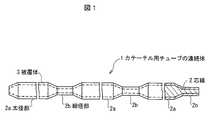
図1は、本発明の第1の実施の形態に係るカテーテル用チューブの連続体1を示す一部断面図である。図2は、本発明の第1の実施の形態に係るカテーテル用チューブ10を示す一部断面図である。尚、太径部2aは、例えば、1800mm、細径部2bは、150mmであるので、太径部の中間部を省略して図示している(以下の図において同じ)。本発明の第1の実施の形態に係るカテーテル用チューブの連続体1は、太径部2aと細径部2bが所定の間隔で連続してなる芯線2と、芯線2上に熱可塑性樹脂を被覆成形して得られた被覆体3と、を有して構成される。また、本発明の第1の実施の形態に係るカテーテル用チューブ10は、カテーテル用チューブの連続体1を、芯線2の太径部2aおよび細径部2bの所定の位置で切断し、芯線2を除去して形成された構成を有する。(First embodiment)
FIG. 1 is a partial cross-sectional view showing a continuous body 1 of catheter tubes according to a first embodiment of the present invention. FIG. 2 is a partial cross-sectional view showing the catheter tube 10 according to the first embodiment of the present invention. Since the large diameter portion 2a is, for example, 1800 mm and the small diameter portion 2b is 150 mm, an intermediate portion of the large diameter portion is omitted for illustration (the same applies to the following drawings). The continuous body 1 for a catheter tube according to the first embodiment of the present invention includes a core wire 2 in which a large-diameter portion 2a and a small-diameter portion 2b are continuous at a predetermined interval, and a thermoplastic resin on the core wire 2. And a covering body 3 obtained by covering molding. Further, the catheter tube 10 according to the first embodiment of the present invention cuts the continuous tube 1 of the catheter tube at predetermined positions of the large diameter portion 2a and the small diameter portion 2b of the core wire 2, and the core wire 2 is cut. It has the structure formed by removing.
芯線2は、銅線、ステンレス軟線等延伸できる金属、または、ポリアミド(PA)等の樹脂ストランドが使用でき、その断面は円形に限定されず、楕円、半円、多角形等任意である。 The core wire 2 can be made of a metal that can be drawn, such as a copper wire or a stainless soft wire, or a resin strand such as polyamide (PA), and the cross section is not limited to a circle, but may be an ellipse, a semicircle, a polygon, or the like.
芯線2は、所定の外径を有する太径部2aと太径部2aより小さい外径を有する細径部2bが所定の間隔で連続して形成されている。すなわち、芯線2は、銅線等の線材が切削等により所定の間隔で縮径され、太径部2aと細径部2bが所定の間隔で連続して形成されたものである。ここで、縮径は、上記の切削に限られず、研磨、研削、鍛造、サンドブラスト、割りダイスを用いた引抜き延伸等の機械的加工によるもの、また、エッチング等の化学的加工によるものでもよい。 The core wire 2 is formed by continuously forming a large diameter portion 2a having a predetermined outer diameter and a small diameter portion 2b having an outer diameter smaller than the large diameter portion 2a at predetermined intervals. That is, the core wire 2 is formed by reducing a diameter of a wire material such as a copper wire at a predetermined interval by cutting or the like, and continuously forming a large diameter portion 2a and a small diameter portion 2b at a predetermined interval. Here, the diameter reduction is not limited to the above-described cutting, but may be by mechanical processing such as polishing, grinding, forging, sandblasting, drawing drawing using a split die, or chemical processing such as etching.
被覆体3は、熱可塑性樹脂が使用でき、低密度ポリエチレン(以下「LDPE」という)、フッ素系樹脂が好ましい。被覆体3は、1層だけではなく2層以上の積層構造にしてもよい。また、手元側から先端側にかけてチューブの剛性が連続或いは段階的に変化するような被覆方法でも良い。 The cover 3 can use a thermoplastic resin, and is preferably a low density polyethylene (hereinafter referred to as “LDPE”) or a fluorine resin. The covering 3 may have a laminated structure of not only one layer but also two or more layers. Further, a covering method in which the rigidity of the tube changes continuously or stepwise from the proximal side to the distal end side may be used.
(第1の実施の形態の効果)
太径部2aを手元側とし、細径部2bを先端側とするカテーテル用チューブにより、手元部の押込み性、送液特性を損なうことなく先端部が柔軟になり、ガイドワイヤー追従性及び耐キンク性が向上する。更に、チューブの延伸加工を行う必要が無いため延伸による歪が無く、加工性が向上し、結果的に低コストのカテーテル用チューブの連続体、及び、カテーテル用チューブが可能となる。(Effects of the first embodiment)
The catheter tube with the large-diameter portion 2a at the proximal side and the small-diameter portion 2b at the distal end side makes the distal end portion flexible without impairing the pushability and liquid feeding characteristics of the proximal portion, and guide wire follow-up and kink resistance Improves. Furthermore, since there is no need to stretch the tube, there is no distortion due to stretching, the workability is improved, and as a result, a low-cost catheter tube continuum and a catheter tube are possible.
(第1の実施の形態に係るカテーテル用チューブの連続体1、カテーテル用チューブ10の製造方法)
図3は、第1の実施の形態に係るカテーテル用チューブの連続体1、及び、カテーテル用チューブ10の製造方法を工程順に示す図である。第1の実施の形態に係るカテーテル用チューブの連続体1の製造方法は、太径部2aと細径部2bが所定の間隔で連続してなる芯線2を準備する芯線準備工程(図3(a))と、芯線2上に熱可塑性樹脂を被覆して被覆体3を形成する被覆体形成工程(図3(b))とを有して構成される。(Manufacturing method of catheter tube continuum 1 and catheter tube 10 according to the first embodiment)
FIG. 3 is a diagram illustrating a method for manufacturing the catheter tube continuous body 1 and the catheter tube 10 according to the first embodiment in the order of steps. The manufacturing method of the continuous body 1 for a catheter tube according to the first embodiment is a core wire preparation step for preparing a core wire 2 in which a large diameter portion 2a and a small diameter portion 2b are continuously provided at a predetermined interval (FIG. 3 ( a)) and a covering body forming step (FIG. 3B) for forming a covering body 3 by coating the core wire 2 with a thermoplastic resin.
第1の実施の形態に係るカテーテル用チューブ10の製造方法は、上記カテーテル用チューブの連続体1の製造工程後、カテーテル用チューブの連続体1を芯線2の太径部2aおよび細径部2bの所定の位置で切断して1本のカテーテル用チューブを切り出す切断工程(図3(c))と、切り出されたカテーテル用チューブから切断された芯線2を除去する芯線除去工程(図3(d))とを有して構成される。 In the method for manufacturing the catheter tube 10 according to the first embodiment, after the manufacturing process of the catheter tube continuous body 1, the catheter tube continuous body 1 is replaced with the large diameter portion 2 a and the small diameter portion 2 b of the core wire 2. A cutting step (FIG. 3C) for cutting out one catheter tube by cutting at a predetermined position of FIG. 3, and a core wire removing step for removing the core wire 2 cut from the cut catheter tube (FIG. 3D). )).
芯線準備工程は、芯線2を切削、研磨、研削、鍛造、割りダイスを用いた引抜き延伸等の機械的加工、または、エッチング等の化学的加工により、所定の外径を有する太径部2aと太径部2aより小さい外径を有する細径部2bが所定の間隔で連続するように縮径加工する工程、または、上記のような縮径加工が施された芯線2を購入等により準備する工程である。 The core wire preparation step is performed by machining the core wire 2 by mechanical processing such as cutting, polishing, grinding, forging, drawing or drawing using a split die, or chemical processing such as etching, and the large diameter portion 2a having a predetermined outer diameter. A step of reducing the diameter so that the small diameter portion 2b having an outer diameter smaller than the large diameter portion 2a continues at a predetermined interval, or the core wire 2 subjected to the diameter reduction processing as described above is prepared by purchase or the like. It is a process.
被覆体形成工程は、熱可塑性樹脂を用い、押出成形機にて所定の成形温度(ダイス温度)で所定の引取スピードで押出し成形する工程である。これにより、略同一肉厚の押出し成形体が得られる。 The covering body forming step is a step of performing extrusion molding at a predetermined take-up speed at a predetermined molding temperature (die temperature) with an extruder using a thermoplastic resin. Thereby, the extrusion molded object of substantially the same wall thickness is obtained.
切断工程は、カテーテル用チューブの連続体1を芯線2の太径部2aおよび細径部2bの所定の位置で切断する工程である。切断方法は切断刃による切断、例えば、シャーリング機械等によるが、芯線2および被覆体3を切断するものであればどのような切断方法であってもよい。 The cutting step is a step of cutting the continuous body 1 of catheter tubes at predetermined positions of the large diameter portion 2a and the small diameter portion 2b of the core wire 2. The cutting method is cutting with a cutting blade, for example, a shearing machine or the like, but any cutting method may be used as long as the core wire 2 and the covering 3 are cut.
芯線除去工程は、切断工程で得られた切断された芯線2の端末の被覆体3の一部を除去し芯線2の一部を露出させてから延伸機に固定し、芯線2の全体を延伸した後、太径部2a側から芯線2を引抜く工程である。 In the core wire removing step, a part of the covering 3 at the end of the cut core wire 2 obtained in the cutting step is removed, and a part of the core wire 2 is exposed and fixed to a drawing machine, and the whole core wire 2 is drawn. Then, the core wire 2 is pulled out from the large diameter portion 2a side.
(実施例1)
外径1.5mmの銅線を、1800mm間隔で150mmセンターレスグラインダーを用いた研削により、1.2mmの外径まで縮径する。芯線2に、熱可塑性樹脂として密度0.920g/cm3 ショア硬度49DのLDPE(熱可塑性樹脂であれば特に限定しない。また熱可塑性樹脂にX線不透過物質を混合しても良い。)を用い、32mm押出成形機にて成形温度200℃(ダイス温度)で約15m/分の引取スピードで押出し成形することで、被覆体3の太径部2aが2.0mm、細径部2bが1.7mmの略同一肉厚の押出し成形体を得る。Example 1
A copper wire having an outer diameter of 1.5 mm is reduced to an outer diameter of 1.2 mm by grinding using a 150 mm centerless grinder at intervals of 1800 mm. LDPE having a density of 0.920 g / cm3 Shore hardness 49D (a thermoplastic resin is not particularly limited as long as it is a thermoplastic resin, and an X-ray opaque material may be mixed with the thermoplastic resin) on the core wire 2. Using a 32 mm extrusion molding machine and extrusion molding at a molding temperature of 200 ° C. (die temperature) at a take-up speed of about 15 m / min, the large-diameter portion 2 a of the covering 3 is 2.0 mm and the small-diameter portion 2 b is 1 An extruded product having a thickness of approximately 7 mm is obtained.
次に、太径部2aの長さが1600mm、細径部2bの長さが100mmとなる位置で切断し、切断で得られた芯線2の両端末の被覆体3を約20mm除去し芯線2を露出させてから延伸機に固定し、芯線2の全体を延伸した後、太径部2a側から芯線2を引抜くことによりカテーテル用チューブが得られる。 Next, cutting is performed at a position where the length of the large diameter portion 2a is 1600 mm and the length of the small diameter portion 2b is 100 mm, and the covering 3 at both ends of the core wire 2 obtained by the cutting is removed by about 20 mm. After being exposed to the wire, it is fixed to a stretching machine, the entire core wire 2 is stretched, and then the core wire 2 is pulled out from the large diameter portion 2a side to obtain a catheter tube.
(比較例1)
外径1.5mm銅線上に、熱可塑性樹脂として密度0.920g/cm3 ショア硬度49DのLDPEを用い(熱可塑性樹脂であれば特に限定しない。また熱可塑性樹脂にX線不透過物質を混合しても良い)、32mm押出成形機にて成形温度200℃(ダイス温度)で約15m/分の引取スピードで押出し成形することで、被覆体外径が2.0mmの成形体を得る。各所定の位置で切断し、切断で得られた物の前記芯線の全体を延伸後引抜くことによりカテーテル用チューブになるカテーテル用原チューブを得た。(Comparative Example 1)
LDPE with a density of 0.920 g / cm3 shore hardness 49D is used as a thermoplastic resin on a copper wire with an outer diameter of 1.5 mm (not limited as long as it is a thermoplastic resin. Also, an X-ray opaque material is mixed with the thermoplastic resin. Alternatively, a molded body having a coating body outer diameter of 2.0 mm is obtained by extrusion molding at a molding temperature of 200 ° C. (die temperature) at a take-up speed of about 15 m / min with a 32 mm extruder. The original tube for catheter which becomes a catheter tube was obtained by cutting at each predetermined position and drawing the whole of the core wire obtained by cutting after drawing.
次に、内径1.7mmのダイスを温度90℃に加熱して、外径1.2mmステンレス芯線を前記カテーテル用チューブの連続体に通したのちに先端200mmを引抜き、太径部1600mmと細径部100mmとなる位置で切断し(太径部及び細径部の径及び長さ寸法は任意で良い)カテーテル用チューブを得た。 Next, a die having an inner diameter of 1.7 mm was heated to a temperature of 90 ° C., and a stainless steel core wire having an outer diameter of 1.2 mm was passed through the continuous body of the catheter tube. The catheter tube was obtained by cutting at a position of 100 mm (the diameter and length of the large diameter portion and the small diameter portion may be arbitrary).
(比較例2)
外径1.2mm銅線上に、熱可塑性樹脂として密度0.920g/cm3 ショア硬度49DのLDPEを用い(熱可塑性樹脂であれば特に限定しない。また熱可塑性樹脂にX線不透過物質を混合しても良い)、32mm押出成形機にて成形温度200℃(ダイス温度)で約15m/分の引取スピードで押出し成形することで、被覆体外径が1.7mmの成形体を得る。所定寸法で切断し、切断で得られた物の前記芯線の全体を延伸後引抜くことによりカテーテル用チューブを得た。(Comparative Example 2)
LDPE with a density of 0.920 g / cm3 Shore hardness 49D is used as a thermoplastic resin on a copper wire with an outer diameter of 1.2 mm (not limited as long as it is a thermoplastic resin. Also, an X-ray opaque material is mixed with the thermoplastic resin. Alternatively, a molded body having a coating body outer diameter of 1.7 mm is obtained by extrusion molding at a molding temperature of 200 ° C. (die temperature) at a take-up speed of about 15 m / min with a 32 mm extruder. The tube for catheter was obtained by cut | disconnecting by the predetermined dimension and drawing the whole said core wire of the thing obtained by cutting | disconnection after extending | stretching.
表1は、実施例1と比較例1、2とを比較し、歪・柔軟性・座屈特性の優劣を示したものである。表2は、実施例1と比較例1の原チューブ、比較例2とを比較し、送液特性の優劣を示したものである。 Table 1 compares Example 1 with Comparative Examples 1 and 2 and shows the superiority or inferiority of strain, flexibility, and buckling characteristics. Table 2 compares the original tube of Example 1 and Comparative Example 1 and Comparative Example 2 and shows the superiority or inferiority of the liquid feeding characteristics.
加熱収縮性能は、100℃のオーブンで5分間加熱した際の軸方向の収縮長さで評価し、この収縮長さを加熱収縮(mm)として、小さい(歪みが小さい)ものを優とする。標線距離は100mmとする。 The heat shrinkage performance is evaluated by the shrinkage length in the axial direction when heated in an oven at 100 ° C. for 5 minutes, and this shrinkage length is defined as heat shrinkage (mm), and small (small distortion) is excellent. The marked line distance is 100 mm.
図4は、カテーテル用チューブの3点曲げ性能を測定する方法を説明するための図である。3点曲げ性能は、支点間距離15mmを速度100mm/分で20mmだけ押込むのに要する最大試験力(N)で評価し、この最大試験力を3点曲げ(N)として、小さいほど柔軟性に優れるとする。尚、試験装置としては、一般的に用いられている強度試験機、押込試験機等が使用できる。 FIG. 4 is a diagram for explaining a method of measuring the three-point bending performance of a catheter tube. Three-point bending performance is evaluated by the maximum test force (N) required to push a distance of 15 mm between fulcrums at a speed of 100 mm / min by 20 mm. The maximum test force is three-point bending (N). It is excellent in. In addition, as a test apparatus, the strength tester generally used, an indentation tester, etc. can be used.
図5は、カテーテル用チューブの座屈性能を(a)、(b)、(c)の手順で測定する方法を説明するための図である。座屈性能は、サンプル長200mmで円を作り(a)、円の直径を小さくして行き(b)、座屈する直前の直径(c)を座屈径(mm)として評価し、この座屈径(mm)が小さいほど座屈特性に優れるとする。
図6は、送液特性を測定する装置の概略を示す図である。スタンド100に支持されたカテーテル用チューブ10にシリンジ101により試験液(水)を所定の押込速度(100mm/分)で送液し、その時の最大力量をデジタルフォースゲージ102で測定することにより送液力量(N)を測定する。
表1の比較結果から、実施例1に係るカテーテル用チューブは、加熱収縮が少なく(歪が少なく)、かつ、座屈特性と柔軟性に優れた細径部を有するとともに、表2の比較結果から、細径部を有するにも係わらず、細径部を有さないものと同等の優れた送液特性を有する。 From the comparison results in Table 1, the catheter tube according to Example 1 has a small diameter portion with little heat shrinkage (less distortion) and excellent in buckling characteristics and flexibility, and the comparison results in Table 2. Therefore, although it has a small diameter portion, it has excellent liquid feeding characteristics equivalent to those having no small diameter portion.
(第2の実施の形態)
図7は、第2の実施形態に係るカテーテル用チューブの連続体1を示す一部断面図である。図8は、第2の実施形態に係るカテーテル用チューブ10を示す一部断面図である。第2の実施形態に係るカテーテル用チューブの連続体1は、太径部2aと細径部2bが所定の間隔で連続してなる芯線2と、芯線2上に熱可塑性樹脂を被覆成形して得られた内層被覆体4aと、内層被覆体4a上に、金属線、樹脂繊維、または、これらを併用して形成された補強層5と、補強層5の少なくとも一部を被覆して一体的に形成された熱可塑性樹脂からなる外層被覆体4bと、を有して構成される。(Second Embodiment)
FIG. 7 is a partial cross-sectional view showing a continuous body 1 of catheter tubes according to a second embodiment. FIG. 8 is a partial cross-sectional view showing the catheter tube 10 according to the second embodiment. The continuous tube 1 for a catheter tube according to the second embodiment includes a core wire 2 in which a large-diameter portion 2a and a small-diameter portion 2b are continuous at a predetermined interval, and a thermoplastic resin is coated and molded on the core wire 2. The obtained inner layer covering 4a and the inner layer covering 4a are integrally formed by covering at least part of the reinforcing layer 5 and the reinforcing layer 5 formed by using metal wires, resin fibers, or a combination thereof. And an outer layer covering body 4b made of a thermoplastic resin.
また、本発明の第2の実施の形態に係るカテーテル用チューブ10は、カテーテル用チューブの連続体1を、芯線2の太径部2aおよび細径部2bの所定の位置で切断し、芯線2を除去して形成された構成を有する。 Further, the catheter tube 10 according to the second embodiment of the present invention cuts the continuous tube 1 of the catheter tube at predetermined positions of the large-diameter portion 2a and the small-diameter portion 2b of the core wire 2, and the core wire 2 is cut. It has the structure formed by removing.
芯線2は、銅線、ステンレス軟線等延伸できる金属、または、ポリアミド(PA)等の樹脂ストランドが使用でき、その断面は円形に限定されず、楕円、半円、多角形等任意である。 The core wire 2 can be made of a metal that can be drawn, such as a copper wire or a stainless soft wire, or a resin strand such as polyamide (PA), and the cross section is not limited to a circle, but may be an ellipse, a semicircle, a polygon, or the like.
芯線2は、所定の外径を有する太径部2aと太径部2aより小さい外径を有する細径部2bが所定の間隔で連続して形成されている。すなわち、芯線2は、銅線等の線材が切削等により所定の間隔で縮径され、太径部2aと細径部2bが所定の間隔で連続して形成されたものである。ここで、縮径は、上記の切削に限られず、研磨、研削、鍛造、サンドブラスト、割りダイスを用いた引抜き延伸等の機械的加工によるもの、また、エッチング等の化学的加工によるものでもよい。 The core wire 2 is formed by continuously forming a large diameter portion 2a having a predetermined outer diameter and a small diameter portion 2b having an outer diameter smaller than the large diameter portion 2a at predetermined intervals. That is, the core wire 2 is formed by reducing a diameter of a wire material such as a copper wire at a predetermined interval by cutting or the like, and continuously forming a large diameter portion 2a and a small diameter portion 2b at a predetermined interval. Here, the diameter reduction is not limited to the above-described cutting, but may be by mechanical processing such as polishing, grinding, forging, sandblasting, drawing drawing using a split die, or chemical processing such as etching.
内層被覆体4aは、熱可塑性樹脂が使用でき、フッ素系樹脂、高密度ポリエチレン(以下、「HDPE」という)等低摩擦材料(X線不透過物質を混合しても良い)が好ましい。尚、内層被覆体4aがフッ素系樹脂で形成されている場合には、内層被覆体4aの表面はケミカルエッチングにより粗面化処理されている。 The inner layer cover 4a can be made of a thermoplastic resin, and is preferably a low friction material such as a fluororesin or high density polyethylene (hereinafter referred to as “HDPE”) (which may contain a radiopaque material). In addition, when the inner layer covering 4a is formed of a fluorine resin, the surface of the inner layer covering 4a is roughened by chemical etching.
補強層5は、白金(Pt)・タングステン(W)等の金属線、樹脂繊維、または、これらの素線を併用して内層被覆体4a上に所定の格子間距離の編組を連続で施されている。補強層5は、同一方向の横巻きや右巻き・左巻き等、巻き方向を変えながら素線を巻きつけても良く、また、巻きピッチや格子間距離に特に限定はない。 The reinforcing layer 5 is a metal wire such as platinum (Pt) / tungsten (W), a resin fiber, or a braid having a predetermined interstitial distance continuously applied to the inner layer covering 4a by using these strands together. ing. The reinforcing layer 5 may be wound with strands while changing the winding direction, such as horizontal winding, right-hand winding, and left-hand winding in the same direction, and the winding pitch and interstitial distance are not particularly limited.
外層被覆体4bは、補強層5の少なくとも一部を被覆して一体的に形成され、内層被覆体4aの外周囲に外層として形成されている。外層被覆体4bは、例えば、ナイロン等の熱可塑性樹脂が使用でき、熱可塑性樹脂にX線不透過物質を混合したものであってもよい。 The outer layer covering 4b is integrally formed by covering at least a part of the reinforcing layer 5, and is formed as an outer layer around the outer periphery of the inner layer covering 4a. For example, a thermoplastic resin such as nylon can be used for the outer layer cover 4b, and a thermoplastic resin mixed with a radiopaque material may be used.
(第2の実施の形態の効果)
太径部2aを手元側とし、細径部2bを先端側とするカテーテル用チューブにより、手元部の押込み性、送液特性を損なうことなく先端部が柔軟になり、ガイドワイヤー追従性及び耐キンク性が向上する。また、チューブの延伸加工を行う必要が無いため延伸による歪が無く、加工性が向上し、結果的に低コストとなる。また、延伸により補強層の巻きピッチ(編組の場合の格子間距離)が拡大することが無いため、先端部の柔軟性及び耐キンク性に優れたカテーテル用チューブの連続体、及び、カテーテル用チューブが可能となる。(Effect of the second embodiment)
The catheter tube with the large-diameter portion 2a at the proximal side and the small-diameter portion 2b at the distal end side makes the distal end portion flexible without impairing the pushability and liquid feeding characteristics of the proximal portion, and guide wire follow-up and kink resistance Improves. In addition, since there is no need to perform tube stretching, there is no distortion due to stretching, and the processability is improved, resulting in lower costs. Further, since the winding pitch of the reinforcing layer (interstitial distance in the case of a braid) does not increase due to stretching, a continuous catheter tube excellent in flexibility and kink resistance at the distal end, and catheter tube Is possible.
(第2の実施の形態に係るカテーテル用チューブの連続体1、カテーテル用チューブ10の製造方法)
第2の実施の形態に係るカテーテル用チューブの連続体1の製造方法は、太径部2aと細径部2bが所定の間隔で連続してなる芯線2を準備する芯線準備工程と、芯線2上に熱可塑性樹脂を被覆して内層被覆体4aを形成する内層被覆体形成工程と、内層被覆体形成工程後に、内層被覆体4a上の少なくとも一部に、金属線、樹脂繊維、または、これらを併用した補強層5を形成する補強層形成工程と、補強層形成工程後に、熱可塑性樹脂により、補強層5および内層被覆体4aを一体に被覆して外層被覆体4bを形成する外層被覆体形成工程とを有して構成される。(Manufacturing method of catheter tube continuum 1 and catheter tube 10 according to the second embodiment)
The manufacturing method of the continuous body 1 for a catheter tube according to the second embodiment includes a core wire preparation step of preparing a core wire 2 in which a large diameter portion 2a and a small diameter portion 2b are continuously provided at a predetermined interval, and a core wire 2 An inner layer covering body forming step for forming an inner layer covering body 4a by coating a thermoplastic resin thereon, and after the inner layer covering body forming step, at least a part of the inner layer covering body 4a is provided with a metal wire, a resin fiber, or these A reinforcing layer forming step for forming the reinforcing layer 5 in combination with the outer layer covering body 4b by integrally covering the reinforcing layer 5 and the inner layer covering body 4a with a thermoplastic resin after the reinforcing layer forming step. Forming process.
第2の実施の形態に係るカテーテル用チューブの10の製造方法は、上記カテーテル用チューブの連続体1の製造工程後、カテーテル用チューブの連続体1を芯線2の太径部2aおよび細径部2bの所定の位置で切断して1本のカテーテル用チューブを切り出す切断工程と、切り出されたカテーテル用チューブから切断された芯線2を除去する芯線除去工程とを有して構成される。 The manufacturing method of the catheter tube 10 according to the second embodiment is such that after the manufacturing process of the catheter tube continuous body 1, the catheter tube continuous body 1 is replaced with the large diameter portion 2a and the small diameter portion of the core wire 2. The cutting process includes a cutting process for cutting out one catheter tube by cutting at a predetermined position 2b, and a core wire removing process for removing the core wire 2 cut from the cut catheter tube.
芯線準備工程、切断工程、および芯線除去工程は、第1の実施の形態の場合と同様であるので説明を省略し、以下に第1の実施の形態と異なる工程について説明する。 Since the core wire preparation step, the cutting step, and the core wire removal step are the same as those in the first embodiment, the description thereof will be omitted, and the steps different from those in the first embodiment will be described below.
内層被覆体形成工程は、熱可塑性樹脂を用い、押出成形機にて所定の成形温度(ダイス温度)で所定の引取スピードで押出し成形する工程である。これにより、略同一肉厚の押出し成形体(内層被覆体4a)が得られる。尚、内層被覆体4aがフッ素系樹脂で形成された場合は、外周表面がケミカルエッチングにより粗面化処理される。 The inner layer covering body forming step is a step of extrusion molding at a predetermined take-up speed at a predetermined forming temperature (die temperature) with an extruder using a thermoplastic resin. Thereby, an extrusion-molded body (inner layer covering body 4a) having substantially the same thickness is obtained. In addition, when the inner layer covering 4a is formed of a fluorine-based resin, the outer peripheral surface is roughened by chemical etching.
補強層形成工程は、白金(Pt)・タングステン(W)等の金属線、樹脂繊維、または、これらの素線を併用して内層被覆体4a上に所定の格子間距離で編組を連続で施す工程である。編組は、同一方向の横巻きや右巻き・左巻き等、巻き方向を変えながら素線を巻きつけても良く、また、巻きピッチや格子間距離に特に限定はない。 In the reinforcing layer forming step, a metal wire such as platinum (Pt) / tungsten (W), a resin fiber, or a combination of these strands is used to continuously braid the inner layer covering 4a with a predetermined interstitial distance. It is a process. The braid may be wound around the wire while changing the winding direction, such as horizontal winding, right-hand winding or left-hand winding in the same direction, and the winding pitch and interstitial distance are not particularly limited.
外層被覆体形成工程は、熱可塑性樹脂を用い、押出成形機にて所定の成形温度(ダイス温度)で所定の引取スピードで、補強層5の少なくとも一部を被覆して、内層被覆体4aの外周囲に外層被覆体4bとして一体的に押出し成形する工程である。 The outer layer covering body forming step uses a thermoplastic resin, covers at least a part of the reinforcing layer 5 at a predetermined take-up speed at a predetermined molding temperature (die temperature) with an extruder, and forms the inner layer covering body 4a. In this process, the outer layer covering 4b is integrally extruded around the outer periphery.
(実施例2)
外径0.8mmの銅線を、1600mm間隔で、150mmセンターレス研磨により0.7mmの外径まで縮径する。芯線2に、熱可塑性樹脂としてフッ素系樹脂であるPFA(旭硝子(株)製 フルオン)を用い(内層被覆体4aに使用する樹脂は熱可塑性樹脂であれば特に限定しないが、フッ素系樹脂であるPTFE・PFAの他にHDPE等低摩擦材料(X線不透過物質を混合しても良い)が望ましい)32mmの押出成形機を用いて成形温度380℃(ダイス温度)、約42m/分の引取スピードで成形することで、太径部2aの被覆径が0.85mm、細径部2bの被覆径が0.75mmの略同一肉厚の押出し成形体を得る。(Example 2)
A copper wire having an outer diameter of 0.8 mm is reduced to an outer diameter of 0.7 mm by 150 mm centerless polishing at intervals of 1600 mm. PFA (Fullon made by Asahi Glass Co., Ltd.) is used as the thermoplastic resin for the core wire 2 (the resin used for the inner layer covering 4a is not particularly limited as long as it is a thermoplastic resin, but is a fluororesin. Low friction material such as HDPE in addition to PTFE / PFA (Preferably X-ray opaque material may be mixed) Using a 32mm extruder, molding temperature is 380 ° C (die temperature), about 42m / min. By molding at a speed, an extruded molded body having substantially the same thickness, in which the coating diameter of the large diameter portion 2a is 0.85 mm and the coating diameter of the small diameter portion 2b is 0.75 mm, is obtained.
この内層被覆体4aをケミカルエッチングにより表面を粗面化した(内層被覆体4aの樹脂がフッ素系樹脂で無い場合この処理は不要)後に、内層被覆体4a上に直径0.03mmのSUS304を用い(素線は白金(Pt)・タングステン(W)等金属線や樹脂繊維でも良い)2本持ちで16打ち格子間距離0.18mmの編組を連続で施し(補強方法は同一方向の横巻きや右巻き・左巻き等巻き方向を変えながら素線を巻きつけても良いし巻きピッチや格子間距離も特に限定しない)、熱可塑性樹脂としてナイロン(アルケマ(株)製PEBAX)を用い(外層被覆体4bも熱可塑性樹脂であれば特に限定しない。また熱可塑性樹脂にX線不透過物質を混合しても良い)、30mmの押出成形機を用いて成形温度220℃(ダイス温度)、約14m/分の引取スピードで押出し成形することで、外層被覆体4bの太径部2aの被覆径が1.1mm、細径部の被覆径が1.0mmの略同一肉厚の押出し成形体を得る。 After the inner layer covering 4a is roughened by chemical etching (when the resin of the inner layer covering 4a is not a fluororesin, this treatment is unnecessary), and SUS304 having a diameter of 0.03 mm is used on the inner layer covering 4a. (The element wire may be a metal wire such as platinum (Pt) / tungsten (W) or a resin fiber) and continuously braided with a striking distance of 0.18 mm between 16 struts. The wire may be wound while changing the winding direction, such as right-handed or left-handed, and the winding pitch and distance between the lattices are not particularly limited. Nylon (PEBAX made by Arkema Co., Ltd.) is used as the thermoplastic resin (outer layer covering) 4b is not particularly limited as long as it is a thermoplastic resin, and a thermoplastic resin may be mixed with an X-ray opaque material), a molding temperature of 220 ° C. (die temperature) using a 30 mm extruder, and about 14 Extrusion molding is performed at a take-off speed of 1 min / min to obtain an extruded molded body having substantially the same thickness, in which the coating diameter of the large-diameter portion 2a of the outer layer coating 4b is 1.1 mm and the coating diameter of the small-diameter portion is 1.0 mm. .
次に、太径部2aと細径部2bの各所定の位置で切断し(太径部及び細径部の径及び長さ寸法は任意で良い)、切断で得られた物の前記芯線全体を延伸した後、太径部2a側から芯線2を引抜くことにより所定のカテーテル用チューブを得た。 Next, the whole core wire of the thing obtained by cutting | disconnecting in each predetermined position of the large diameter part 2a and the small diameter part 2b (The diameter and length dimension of a large diameter part and a small diameter part may be arbitrary), and cutting Then, the core wire 2 was pulled out from the large diameter portion 2a side to obtain a predetermined catheter tube.
(第3の実施の形態)
第3の実施の形態に係るカテーテル用チューブの連続体1は、太径部2aと細径部2bが所定の間隔で連続してなる芯線2と、芯線2上に熱可塑性樹脂を被覆成形して得られた内層被覆体4aと、内層被覆体4a上に、金属線、樹脂繊維、または、これらを併用して形成された補強層5と、補強層5の少なくとも一部を被覆して一体的に形成された熱可塑性樹脂からなる外層被覆体4bと、を有して構成される。上記の補強層5は、金属線又は樹脂繊維の何れか又はこれらを併用した線材を芯線2の軸方向に縦沿わせた補強体5aを含む。(Third embodiment)
A continuous body 1 for a catheter tube according to a third embodiment includes a core wire 2 in which a large-diameter portion 2a and a small-diameter portion 2b are continuously provided at a predetermined interval, and a thermoplastic resin is coated on the core wire 2. The inner layer covering 4a obtained in this manner, and the reinforcing layer 5 formed by using a metal wire, a resin fiber, or a combination thereof, and at least a part of the reinforcing layer 5 are integrally formed on the inner layer covering 4a. And an outer layer covering body 4b made of a thermoplastic resin. The reinforcing layer 5 includes a reinforcing body 5a in which either a metal wire or a resin fiber or a wire material using both of them is vertically aligned in the axial direction of the core wire 2.
図9は、第3の実施の形態に係るカテーテル用チューブの連続体1から切り出されたカテーテル用チューブ10を示す一部断面図である。本発明の第3の実施の形態に係るカテーテル用チューブ10は、カテーテル用チューブの連続体1を、芯線2の太径部2aおよび細径部2bの所定の位置で切断し、芯線2を除去して形成された構成を有する。 FIG. 9 is a partial cross-sectional view showing the catheter tube 10 cut out from the catheter tube continuum 1 according to the third embodiment. The catheter tube 10 according to the third embodiment of the present invention cuts the continuous tube 1 of the catheter tube at a predetermined position of the large diameter portion 2a and the small diameter portion 2b of the core wire 2, and removes the core wire 2. It has the structure formed.
芯線2、内層被覆体4a、補強層5、外層被覆体4bは、第2の実施の形態の場合と同様であるので、説明を省略する。 Since the core wire 2, the inner layer covering 4a, the reinforcing layer 5, and the outer layer covering 4b are the same as those in the second embodiment, the description thereof is omitted.
補強体5aは、白金(Pt)・タングステン(W)等の金属線、樹脂繊維、または、これらの素線を併用して内層被覆体4a上に芯線2の軸方向に縦沿わせたものであり、編組である補強層5と共に、チューブの補強を行なうものである。尚、補強体5aは、1または2以上の素線を内層被覆体4a上に縦沿わせる。 The reinforcing body 5a is a metal wire such as platinum (Pt) / tungsten (W), a resin fiber, or a combination of these strands, and is vertically aligned in the axial direction of the core wire 2 on the inner layer covering 4a. Yes, together with the reinforcing layer 5 which is a braid, the tube is reinforced. The reinforcing body 5a causes one or more strands to run vertically on the inner layer covering body 4a.
(第3の実施の形態の効果)
太径部2aを手元側とし、細径部2bを先端側とするカテーテル用チューブにより、手元部の押込み性、送液特性を損なうことなく先端部が柔軟になり、ガイドワイヤー追従性及び耐キンク性が向上する。また、チューブの延伸加工を行う必要が無いため延伸による歪が無く、加工性が向上し、結果的に低コストとなる。また、延伸により補強層の巻きピッチ(編組の場合の格子間距離)が拡大することが無いため、先端部の柔軟性及び耐キンク性に優れる。さらに芯線2の軸方向に縦沿わせた補強体5aにより長さ方向の寸法変化が小さいカテーテル用チューブの連続体、及び、カテーテル用チューブが可能となる。(Effect of the third embodiment)
The catheter tube with the large-diameter portion 2a at the proximal side and the small-diameter portion 2b at the distal end side makes the distal end portion flexible without impairing the pushability and liquid feeding characteristics of the proximal portion, and guide wire follow-up and kink resistance Improves. In addition, since there is no need to perform tube stretching, there is no distortion due to stretching, and the processability is improved, resulting in lower costs. Moreover, since the winding pitch of the reinforcing layer (interstitial distance in the case of a braid) does not increase by stretching, the tip portion is excellent in flexibility and kink resistance. Furthermore, the continuous body of the catheter tube with a small dimensional change in the length direction and the catheter tube can be achieved by the reinforcing body 5a longitudinally along the axial direction of the core wire 2.
(第3の実施の形態に係るカテーテル用チューブの連続体1、カテーテル用チューブ10の製造方法)
第3の実施の形態に係るカテーテル用チューブの連続体1の製造方法は、太径部2aと細径部2bが所定の間隔で連続してなる芯線2を準備する芯線準備工程と、芯線2上に熱可塑性樹脂を被覆して内層被覆体4aを形成する内層被覆体形成工程と、内層被覆体形成工程後に、内層被覆体4a上の少なくとも一部に、金属線、樹脂繊維、または、これらを併用した所定の格子間距離の編組及び芯線2の軸方向に縦沿わせた補強体5aを形成する補強層形成工程と、補強層形成工程後に、熱可塑性樹脂により、補強層5および内層被覆体4aを一体に被覆して外層被覆体4bを形成する外層被覆体形成工程とを有して構成される。(Manufacturing method of catheter tube continuum 1 and catheter tube 10 according to the third embodiment)
The manufacturing method of the continuous body 1 for a catheter tube according to the third embodiment includes a core wire preparation step of preparing a core wire 2 in which a large diameter portion 2a and a small diameter portion 2b are continuously provided at predetermined intervals, and a core wire 2 An inner layer covering body forming step for forming an inner layer covering body 4a by coating a thermoplastic resin thereon, and after the inner layer covering body forming step, at least a part of the inner layer covering body 4a is provided with a metal wire, a resin fiber, or these A reinforcing layer forming step for forming a braid having a predetermined interstitial distance and a reinforcing body 5a longitudinally along the axial direction of the core wire 2, and a reinforcing layer 5 and an inner layer covering with a thermoplastic resin after the reinforcing layer forming step. And an outer layer covering body forming step of forming the outer layer covering body 4b by integrally covering the body 4a.
第3の実施の形態に係るカテーテル用チューブ10の製造方法は、上記カテーテル用チューブの連続体1の製造工程後、カテーテル用チューブの連続体1を芯線2の太径部2aおよび細径部2bの所定の位置で切断して1本のカテーテル用チューブを切り出す切断工程と、切り出されたカテーテル用チューブから切断された芯線2を除去する芯線除去工程とを有して構成される。 In the method for manufacturing the catheter tube 10 according to the third embodiment, after the manufacturing process of the catheter tube continuous body 1, the catheter tube continuous body 1 is replaced with the large diameter portion 2 a and the small diameter portion 2 b of the core wire 2. And a cutting step for cutting out one catheter tube by cutting at a predetermined position, and a core wire removing step for removing the core wire 2 cut from the cut catheter tube.
芯線準備工程、切断工程、および芯線除去工程は、第2の実施の形態の場合と同様であるので説明を省略し、以下に第2の実施の形態と異なる工程について説明する。 Since the core wire preparation step, the cutting step, and the core wire removal step are the same as those in the second embodiment, description thereof will be omitted, and the steps different from those in the second embodiment will be described below.
補強層形成工程は、白金(Pt)・タングステン(W)等の金属線、樹脂繊維、または、これらの素線を併用して内層被覆体4a上に芯線2の軸方向に縦沿わせた補強体5aを形成し、この縦沿わせた補強体5aの上に、白金(Pt)・タングステン(W)等の金属線、樹脂繊維、または、これらの素線を併用して所定の格子間距離で編組を連続で施す工程である。 In the reinforcing layer forming step, a metal wire such as platinum (Pt) / tungsten (W), a resin fiber, or a combination of these strands is used to reinforce along the axial direction of the core wire 2 on the inner layer covering 4a. The body 5a is formed, and a metal wire such as platinum (Pt) / tungsten (W), a resin fiber, or a combination of these strands is used on the longitudinally reinforced body 5a to form a predetermined interstitial distance. In this step, the braid is continuously applied.
(実施例3)
外径0.8mmの銅線を、1800mm間隔で、120mm、センターレス研磨により0.7mmの外径まで縮径して芯線2を作製する。芯線2に、熱可塑性樹脂としてPFA(旭硝子(株)製フルオン)を用い、32mmの押出成形機を用いて成形温度380℃(ダイス温度)、約42m/分の引取スピードで成形することで、太径部2aの被覆径が0.85mm、細径部の被覆径が0.75mmの略同一肉厚の押出し成形体を得る。この内層被覆体4aをケミカルエッチングにより表面を粗面化した後に、内層被覆体4a上に直径0.03mmの樹脂繊維(クラレ(株)製ベクトラン)2本を縦沿わせた上に(軸方向の補強素線は樹脂繊維線が望ましいが金属線でも良い)、直径0.03mmのSUS304を用い、2本持ちで16打ち格子間距離0.18mmの編組を連続で施し(補強方法は同一方向の横巻きや右巻き・左巻き等巻き方向を変えながら素線を巻きつけても良い)、熱可塑性樹脂としてナイロン(アルケマ(株)製PEBAX)を用い(外層被覆体4bも熱可塑性樹脂であれば特に限定しない)、30mmの押出成形機を用いて成形温度220℃(ダイス温度)、約14m/分の引取スピードで押出し成形することで、外層被覆体4bの太径部2aの被覆径が1.1mm、細径部の被覆径が1.0mmの略同一肉厚の押出し成形体を得る。(Example 3)
The core wire 2 is manufactured by reducing the diameter of a copper wire having an outer diameter of 0.8 mm to an outer diameter of 0.7 mm by 120 mm and centerless polishing at intervals of 1800 mm. By using PFA (Fullon made by Asahi Glass Co., Ltd.) as the thermoplastic resin for the core wire 2, by molding at a molding temperature of 380 ° C. (die temperature) and a take-up speed of about 42 m / min using a 32 mm extruder. An extruded product having substantially the same wall thickness is obtained in which the coating diameter of the large diameter portion 2a is 0.85 mm and the coating diameter of the small diameter portion is 0.75 mm. After the surface of the inner layer covering 4a is roughened by chemical etching, two resin fibers (Vectran manufactured by Kuraray Co., Ltd.) having a diameter of 0.03 mm are vertically aligned on the inner layer covering 4a (in the axial direction). Resin fiber wire is desirable, but a metal fiber may be used as the reinforcing element wire, and SUS304 having a diameter of 0.03 mm is used, and a braid with a distance of 0.18 mm between 16 struts is applied continuously (reinforcing method is in the same direction) Horizontal winding, right-handed, left-handed, etc., the wire may be wound while changing the winding direction), and nylon (PEBAX made by Arkema Co., Ltd.) is used as the thermoplastic resin (the outer layer covering 4b may also be a thermoplastic resin) If it is extrusion-molded at a molding temperature of 220 ° C. (die temperature) and a take-up speed of about 14 m / min using a 30 mm extruder, the coating diameter of the large-diameter portion 2a of the outer layer covering 4b Is an extruded body having a thickness of approximately the same thickness of 1.1 mm and a coating diameter of the small diameter portion of 1.0 mm.
次に、太径部2aと細径部2bの各所定の位置で切断し(太径部及び細径部の径及び長さ寸法は任意で良い)、切断で得られた物の前記芯線全体を延伸した後、太径部2a側から芯線2を引抜くことにより所定のカテーテル用チューブを得た。 Next, the whole core wire of the thing obtained by cutting | disconnecting in each predetermined position of the large diameter part 2a and the small diameter part 2b (The diameter and length dimension of a large diameter part and a small diameter part may be arbitrary), and cutting Then, the core wire 2 was pulled out from the large diameter portion 2a side to obtain a predetermined catheter tube.
(第4の実施の形態)
第4の実施形態に係るカテーテル用チューブの連続体1およびカテーテル用チューブ10は、第2の実施の形態または第3の実施の形態における構成と同じであるが、製造方法が異なるので、以下に第4の実施の形態に係るカテーテル用チューブの連続体1、カテーテル用チューブ10の製造方法について説明する。(Fourth embodiment)
The catheter tube continuum 1 and the catheter tube 10 according to the fourth embodiment are the same as those in the second embodiment or the third embodiment, but the manufacturing method is different. A method for manufacturing the catheter tube continuum 1 and the catheter tube 10 according to the fourth embodiment will be described.
(第4の実施の形態に係るカテーテル用チューブの連続体1、カテーテル用チューブ10の製造方法)
図10は、第4の実施の形態に係るカテーテル用チューブの連続体1、及び、カテーテル用チューブ10の製造方法を工程順に示す図である。第4の実施の形態に係るカテーテル用チューブの連続体1の製造方法は、均一な外径を有する連続した芯線20を準備する芯線準備工程(図10(a))と、芯線20上に熱可塑性樹脂を被覆して内層被覆体4aを形成する内層被覆体形成工程(図10(b))と、内層被覆体形成工程後に、芯線20と内層被覆体4aを同時に部分延伸する延伸工程(図10(c))と、延伸工程後に、内層被覆体4a上の少なくとも一部に、金属線、樹脂繊維、またはこれらを併用した所定の格子間距離の編組、または、芯線20の軸方向に縦沿わせた補強体5aを形成する補強層形成工程(図10(d))と、補強層形成工程後に、熱可塑性樹脂により、補強層5および内層被覆体4aを一体に被覆して外層被覆体4bを形成する外層被覆体形成工程(図10(e))とを有して構成される。(Manufacturing method of catheter tube continuum 1 and catheter tube 10 according to the fourth embodiment)
FIG. 10 is a diagram showing a catheter tube continuous body 1 and a method for manufacturing the catheter tube 10 according to the fourth embodiment in the order of steps. The manufacturing method of the continuous body 1 for a catheter tube according to the fourth embodiment includes a core wire preparation step (FIG. 10A) for preparing a continuous core wire 20 having a uniform outer diameter, and heat on the core wire 20. An inner layer covering body forming step (FIG. 10B) for forming an inner layer covering body 4a by coating a plastic resin, and a stretching step for partially stretching the core wire 20 and the inner layer covering body 4a simultaneously after the inner layer covering body forming step (FIG. 10 (c)) and at least part of the inner layer covering 4a after the stretching step, a metal wire, a resin fiber, or a braid having a predetermined interstitial distance using these together, or longitudinally in the axial direction of the core wire 20 After the reinforcing layer forming step (FIG. 10 (d)) for forming the along reinforcing body 5a and the reinforcing layer forming step, the reinforcing layer 5 and the inner layer covering body 4a are integrally covered with a thermoplastic resin so as to cover the outer layer covering body. 4b forming outer layer covering ( Configured to have a 10 (e)).
第4の実施の形態に係るカテーテル用チューブの10の製造方法は、上記カテーテル用チューブの連続体1の製造工程後、カテーテル用チューブの連続体1を芯線20の太径部2aおよび細径部2bの所定の位置で切断して1本のカテーテル用チューブを切り出す切断工程(図10(f))と、切り出されたカテーテル用チューブから切断された芯線20を除去する芯線除去工程(図10(g))とを有して構成される。 In the method for manufacturing the catheter tube 10 according to the fourth embodiment, after the manufacturing process of the catheter tube continuous body 1, the catheter tube continuous body 1 is replaced by the large diameter portion 2 a and the small diameter portion of the core wire 20. A cutting step (FIG. 10 (f)) of cutting at a predetermined position 2b to cut out one catheter tube, and a core wire removing step (FIG. 10 (f)) of removing the core wire 20 cut from the cut catheter tube. g)).
切断工程、および芯線除去工程は、第2または第3の実施の形態の場合と同様であるので説明を省略し、以下に第2または第3の実施の形態と異なる工程について説明する。 Since the cutting step and the core wire removal step are the same as those in the second or third embodiment, the description thereof will be omitted, and the steps different from those in the second or third embodiment will be described below.
芯線準備工程は、所定の一定の外径を有する芯線20を加工、または、購入等により準備する工程である。 The core wire preparation step is a step of preparing the core wire 20 having a predetermined constant outer diameter by processing or purchasing.
延伸工程は、芯線20と内層被覆体4aを熱風加熱装置により所定の表面温度に予熱した直後に、その一部分を2個のエアーチャックで固定し、所定の速度で所定量だけ延伸し、所定の芯線20の外径、所定の内層被覆体4aの外径をそれぞれ有する太径部2aおよび細径部2bを形成する。 In the stretching step, immediately after the core wire 20 and the inner layer covering 4a are preheated to a predetermined surface temperature by a hot air heating device, a part thereof is fixed by two air chucks, and stretched by a predetermined amount at a predetermined speed, A large-diameter portion 2a and a small-diameter portion 2b each having an outer diameter of the core wire 20 and an outer diameter of a predetermined inner layer covering 4a are formed.
(第4の実施の形態の効果)
太径部2aを手元側とし、細径部2bを先端側とするカテーテル用チューブにより、手元部の押込み性、送液特性を損なうことなく先端部が柔軟になり、ガイドワイヤー追従性及び耐キンク性が向上する。また、内層被覆体4aが部分延伸された際の延伸歪は、外層被覆体4bの被覆時に加熱溶融一体化されることにより軽減されるので、一体化されたカテーテル用チューブは延伸による残留応力が減少する。これにより、先端部の柔軟性及び耐キンク性に優れたカテーテル用チューブの製造方法が提供できる。さらに、芯線20に縦沿わせた補強体5aを有する場合は、上記の効果に加え、軸方向に配置された補強部材により長さ方向の寸法変化が小さいカテーテル用チューブの連続体、及び、カテーテル用チューブが可能となる。(Effect of the fourth embodiment)
The catheter tube with the large-diameter portion 2a at the proximal side and the small-diameter portion 2b at the distal end side makes the distal end portion flexible without impairing the pushability and liquid feeding characteristics of the proximal portion, and guide wire follow-up and kink resistance Improves. In addition, since the stretching strain when the inner layer covering 4a is partially stretched is reduced by heat-melting integration when the outer layer covering 4b is coated, the integrated catheter tube has a residual stress due to stretching. Decrease. Thereby, the manufacturing method of the tube for catheters excellent in the softness | flexibility and kink resistance of a front-end | tip part can be provided. Further, in the case of having the reinforcing body 5a vertically aligned with the core wire 20, in addition to the above effects, a continuous body of catheter tube having a small dimensional change in the length direction due to the reinforcing member arranged in the axial direction, and the catheter Tube is possible.
(実施例4)
芯線20としての外径0.8mmの銅線上に、熱可塑性樹脂として PFA(旭硝子(株)製フルオン )を用い、32mmの押出成形機を用いて成形温度380℃(ダイス温度)、約42m/分の引取スピードで押出成形により外径0.85mmの内層被覆体4aを被覆成形したのちに、芯線20と内層被覆体4aを熱風加熱装置により表面温度170℃に予熱した直後に、その一部分(1600mm間隔で120mm)を2個のエアーチャックで固定し、50mm/分の速度で36mm延伸し、芯線20の外径0.7mm、内層被覆体4aの外径0.74mmの細径部2bを作製する。この内層被覆体4aをケミカルエッチングにより表面を粗面化した後に、内層被覆体4a上に直径0.03mmのSUS304を用い、2本持ちで16打ち格子間距離0.18mmの編組を連続で施した上に、熱可塑性樹脂としてナイロン(アルケマ(株)製PEBAX)を用い、30mmの押出成形機を用いて成形温度220℃(ダイス温度)、約14m/分の引取スピードで成形することで、太径部2aの被覆径が1.1mm、細径部2bの被覆径が0.99mmの略同一肉厚の押出し成形体を得る。Example 4
On a copper wire having an outer diameter of 0.8 mm as the core wire 20, PFA (Fullon manufactured by Asahi Glass Co., Ltd.) is used as a thermoplastic resin, and a molding temperature of 380 ° C. (die temperature) is about 42 m / mm using a 32 mm extruder. After the inner layer covering 4a having an outer diameter of 0.85 mm is formed by extrusion at a take-up speed of minutes, immediately after the core wire 20 and the inner layer covering 4a are preheated to a surface temperature of 170 ° C. by a hot air heating device, a part ( 1600 mm and 120 mm) is fixed with two air chucks, and is stretched 36 mm at a speed of 50 mm / min. The core wire 20 has an outer diameter 0.7 mm and the inner layer covering 4 a has an outer diameter 0.74 mm of a small diameter portion 2 b. Make it. After roughening the surface of the inner layer covering 4a by chemical etching, SUS304 having a diameter of 0.03 mm is used on the inner layer covering 4a, and a braid having a distance of 0.18 mm with 16 struts is continuously applied. In addition, by using nylon (PEBAX made by Arkema Co., Ltd.) as a thermoplastic resin, by molding using a 30 mm extrusion molding machine at a molding temperature of 220 ° C. (die temperature) and a take-up speed of about 14 m / min, An extruded product having substantially the same thickness is obtained in which the coating diameter of the large diameter portion 2a is 1.1 mm and the coating diameter of the small diameter portion 2b is 0.99 mm.
次に、太径部2aと細径部2bの各所定の位置で切断し(太径部及び細径部の径及び長さ寸法は任意で良い)、切断で得られた物の前記芯線全体を延伸した後、太径部2a側から芯線20を引抜くことにより所定のカテーテル用チューブを得た。 Next, the whole core wire of the thing obtained by cutting | disconnecting in each predetermined position of the large diameter part 2a and the small diameter part 2b (The diameter and length dimension of a large diameter part and a small diameter part may be arbitrary), and cutting Then, the core wire 20 was pulled out from the large diameter portion 2a side to obtain a predetermined catheter tube.
(比較例3)
外径0.8mmの銅線上に熱可塑性樹脂としてPFA(旭硝子(株)製フルオン )を用い、32mmの押出成形機を用いて成形温度380℃(ダイス温度)、約42m/分の引取スピードで押出成形により外径0.85mmの内層被覆体を被覆成形したのちに、芯線と内層被覆体を熱風加熱装置により表面温度170℃に予熱した直後に、その一部分(1600mm間隔で120mm)を2個のエアーチャックで固定し、50mm/分の速度で36mm延伸し、芯材外径0.7mm、内層被覆体外径0.74mmの細径部を作成する。(Comparative Example 3)
Using PFA (Fullon manufactured by Asahi Glass Co., Ltd.) as a thermoplastic resin on a copper wire with an outer diameter of 0.8 mm, using a 32 mm extrusion molding machine at a molding temperature of 380 ° C. (die temperature) at a take-up speed of about 42 m / min. After the inner layer covering with an outer diameter of 0.85 mm is formed by extrusion molding, immediately after the core wire and the inner layer covering are preheated to a surface temperature of 170 ° C. with a hot air heating device, two parts (120 mm at intervals of 1600 mm) are provided. And is stretched by 36 mm at a speed of 50 mm / min to create a small diameter portion having a core material outer diameter of 0.7 mm and an inner layer covering outer diameter of 0.74 mm.
この内層被覆体をケミカルエッチングにより表面を粗面化した後に、内層被覆体上に直径0.03mmのSUS304を用い、2本持ちで16打ち格子間距離0.18mmの編組を連続で施した上に、熱可塑性樹脂としてナイロン(アルケマ(株)製PEBAX)を用い、30mmの押出成形機を用いて成形温度220℃(ダイス温度)、約14m/分の引取スピードで成形することで、太径部の被覆径が1.1mm、細径部の被覆径が0.99mmの略同一肉厚の押出し成形体を得る。次に、太径部と細径部の各所定の位置で切断し芯線の全体を延伸した後、太径部から芯線を引抜くことにより所定のカテーテル用チューブを得た。 After roughening the surface of this inner layer covering by chemical etching, SUS304 having a diameter of 0.03 mm was used on the inner layer covering, and a braid having a 16-strike distance of 0.18 mm was continuously applied. In addition, by using nylon (PEBAX manufactured by Arkema Co., Ltd.) as a thermoplastic resin, and molding using a 30 mm extrusion molding machine at a molding temperature of 220 ° C. (die temperature) and a take-up speed of about 14 m / min, An extruded product having substantially the same wall thickness with a coating diameter of 1.1 mm and a coating diameter of the small diameter part of 0.99 mm is obtained. Next, after cutting at predetermined positions of the large diameter portion and the small diameter portion to stretch the entire core wire, the core wire was pulled out from the large diameter portion to obtain a predetermined catheter tube.
(比較例4)
外径0.7mmの銅線上に、熱可塑性樹脂としてPFA(旭硝子(株)製フルオン)を用い、32mmの押出成形機を用いて成形温度380℃(ダイス温度)、約42m/分の引取スピードで押出し成形することで被覆外径が0.75mmの内層被覆体を得る。この内層被覆体上に、直径0.03mmのSUS304を用い、2本持ちで16打ち格子間距離0.18mmの編組を連続で施し、熱可塑性樹脂としてナイロン(アルケマ(株)製PEBAX)を用い、30mmの押出成形機を用いて成形温度220℃(ダイス温度)、約14m/分の引取スピードで押出し成形することで、被覆径が0.99mmの押出し成形体を得る。各所定の位置で切断し、切断で得られた物の芯線の全体を延伸した後、この芯線を引抜くことにより所定のカテーテル用チューブを得た。(Comparative Example 4)
Using a PFA (Fullon manufactured by Asahi Glass Co., Ltd.) as a thermoplastic resin on a copper wire with an outer diameter of 0.7 mm, using a 32 mm extruder, a molding temperature of 380 ° C. (die temperature), and a take-up speed of about 42 m / min. The inner layer covering with a coating outer diameter of 0.75 mm is obtained by extrusion molding. On this inner layer covering, SUS304 having a diameter of 0.03 mm was used, and a braid having a distance of 0.18 mm and 16 striking lattices was continuously applied, and nylon (PEBAX made by Arkema Co., Ltd.) was used as the thermoplastic resin. Using an extrusion molding machine of 30 mm, extrusion molding is performed at a molding temperature of 220 ° C. (die temperature) and a take-up speed of about 14 m / min, thereby obtaining an extrusion molded body having a coating diameter of 0.99 mm. After cutting at each predetermined position and extending the entire core wire of the product obtained by cutting, the core wire was pulled out to obtain a predetermined catheter tube.
表3は、実施例2〜4と比較例3とを比較し、歪・柔軟性・座屈特性の優劣を示したものである。測定は細径部で行なった。表4は、実施例2〜4と比較例3、4の原チューブとを比較し、送液特性の優劣を示したものである。尚、試験に使用したチューブは全長1700mmとした。
表3の比較結果から、実施例2〜4は、座屈特性と柔軟性に優れ、かつ、加熱収縮の少ない細径部を有する。また、表4の比較結果から、実施例2〜4は細径部を有するにも係わらず、細径部を有さない比較例3の原チューブと同等の送液特性を有する。以上から、実施例2〜4は、座屈特性、柔軟性、加熱特性、及び、送液特性に優れている。 From the comparison result of Table 3, Examples 2-4 have a small diameter part which is excellent in buckling characteristics and flexibility, and has little heat shrinkage. Moreover, from the comparison result of Table 4, although Examples 2-4 have a thin diameter part, they have a liquid feeding characteristic equivalent to the original tube of the comparative example 3 which does not have a thin diameter part. From the above, Examples 2 to 4 are excellent in buckling characteristics, flexibility, heating characteristics, and liquid feeding characteristics.
表5は、降伏強度を比較した結果である。引張試験により得られた曲線より形状が復元する強度の最大値を測定し、これをそれぞれ降伏強度とした。実施例4と比較例3は軸補強部材の有無のみの違いであるため、降伏強度の差を伸び難さとして比較検討した。
表5の比較結果から、軸方向の補強部材を有することを特徴とする実施例4は比較例3と比較し長さ方向に伸び難い特性を有する。また、表4の比較結果から、実施例4は細径部を有するにも係わらず、細径部を有さない比較例3の原チューブと同等の送液特性を有すると共に、座屈特性、柔軟性に優れ、加熱収縮の少ない細径部を有するカテーテル用チューブが提供できる。 From the comparison result of Table 5, Example 4 characterized by having a reinforcing member in the axial direction has a characteristic that it is difficult to extend in the length direction as compared with Comparative Example 3. Moreover, from the comparison result of Table 4, while Example 4 has a thin diameter part, it has the liquid feeding characteristic equivalent to the original tube of the comparative example 3 which does not have a thin diameter part, and buckling characteristic, A catheter tube having a small diameter portion with excellent flexibility and less heat shrinkage can be provided.
(実施例5)
図11は、実施例1のカテーテル用チューブの変形例を示すものである。カテーテル用チューブ10は、複数層の被覆体で構成されていてもよく、図11では、第1被覆体30aと第2被覆体30bとで構成されたカテーテル用チューブ10を示す。また、手元側から先端側にかけてチューブの剛性が連続或いは段階的に変化するような被覆方法でもよく、第1被覆体30aは手元側で厚く先端側にかけて薄く成形され、第2被覆体30bは手元側で薄く先端側にかけて厚く成形されている。これにより、手元部の押込み性、ガイドワイヤー追従性等の性能向上をさらに図ることができる。(Example 5)
FIG. 11 shows a modification of the catheter tube of the first embodiment. The catheter tube 10 may be composed of a multi-layer covering. FIG. 11 shows the catheter tube 10 composed of a first covering 30a and a second covering 30b. Further, a coating method in which the rigidity of the tube changes continuously or stepwise from the proximal side to the distal end side may be employed. The first covering body 30a is thickly formed at the proximal side and thinly formed toward the distal end side, and the second covering body 30b is disposed at the proximal side. It is thinly formed on the side and thick on the tip side. Thereby, performance improvement, such as pushing property of a hand part and guide wire followability, can further be aimed at.
(実施例6)
図12は、実施例1のカテーテル用チューブの別の変形例を示すものである。カテーテル用チューブ10の内腔は1つ以上あればよく、図12では、内腔31a、31bの2つの内腔がある。この内腔は縮径された芯線により形成されるが、1つ以上の芯線が縮径されていればよい。図12の例では、A−A断面では内腔31aは縮径された芯線により形成されているが、B−B断面では内腔31bは縮径されていない芯線により形成されている例を示している。すなわち、内腔31aのみが縮径されている。(Example 6)
FIG. 12 shows another modification of the catheter tube of the first embodiment. There may be one or more lumens of the catheter tube 10, and in FIG. 12, there are two lumens 31a and 31b. This lumen is formed by a core wire having a reduced diameter, but it is sufficient that one or more core wires have a reduced diameter. In the example of FIG. 12, the lumen 31a is formed by a core wire having a reduced diameter in the AA cross section, but the lumen 31b is formed by a core wire not having a reduced diameter in the BB cross section. ing. That is, only the lumen 31a is reduced in diameter.
(実施例7)
図13は、実施例2〜4の補強層を有するカテーテル用チューブの変形例を示すもので、先端部の内径が縮径され、被覆体の硬度や外径が手元側から先端にかけて段階的に低減している構造を示す図である。(Example 7)
FIG. 13 shows a modification of the catheter tube having the reinforcing layers of Examples 2 to 4, in which the inner diameter of the distal end portion is reduced, and the hardness and outer diameter of the covering are gradually increased from the proximal side to the distal end. It is a figure which shows the structure which is reducing.
図13(a)は、補強層5を形成後、所定寸法に切断し、所定の外層4cを構成するようにして作られた熱収縮チューブを被せて溶融一体化させた構造のカテーテル用チューブである。図13(b)は、補強体5の一部を除去して外層被覆体4bを被覆することにより編組部と非編組部を有する構造のカテーテル用チューブである。図13(c)は、実施例2〜4のカテーテル用チューブ10に、外層積層体4dが積層された構造のカテーテル用チューブである。 FIG. 13A shows a catheter tube having a structure in which a reinforcing layer 5 is formed, cut to a predetermined size, and covered with a heat-shrinkable tube that is formed to constitute a predetermined outer layer 4c. is there. FIG. 13B is a catheter tube having a structure having a braided portion and a non-braided portion by removing a part of the reinforcing body 5 and covering the outer layer covering 4b. FIG.13 (c) is the catheter tube of the structure where the outer layer laminated body 4d was laminated | stacked on the catheter tube 10 of Examples 2-4.
(実施例8)
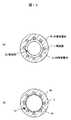
図14(a)、(b)は、実施例2〜4の補強層を有するカテーテル用チューブの断面を示すもので、実施例2〜4の別の断面形状を示す一例である。図14(a)は、内腔形状が異型(楕円、半円等)の断面形状の例、図14(b)は、内腔形状がマルチルーメンである場合の断面形状の例である。(Example 8)
FIGS. 14A and 14B show a cross section of a catheter tube having a reinforcing layer of Examples 2 to 4, and are examples showing other cross-sectional shapes of Examples 2 to 4. FIG. FIG. 14A shows an example of a cross-sectional shape with a different lumen shape (ellipse, semicircle, etc.), and FIG. 14B shows an example of a cross-sectional shape when the lumen shape is multi-lumen.
(実施例9)
図15(a)、(b)は、実施例3または4の補強層5に補強体5aを含むカテーテル用チューブの断面を示すもので、内層被覆体4a或いは外層被覆体4b中に埋込まれている構造の例である。尚、軸方向補強部材としての補強体5aは1本以上であればよい。Example 9
FIGS. 15A and 15B show a cross section of a catheter tube including the reinforcing body 5a in the reinforcing layer 5 of Example 3 or 4, and are embedded in the inner layer covering body 4a or the outer layer covering body 4b. This is an example of a structure. In addition, the reinforcement body 5a as an axial direction reinforcement member should just be one or more.
(実施例10)
図16(a)、(b)は、実施例3または4の補強層5に補強体5aを含むカテーテル用チューブとその右断面(外層被覆体4bは図示せず)を示すもので、補強層5と補強体5aとの位置関係が実施例3または4と異なる構成の例である。図16(a)は、補強体5aが補強層5と一体化した構成、すなわち、補強層5と補強体5aとを一緒に編組して形成した構成の例である。また、図16(b)は、補強体5aが補強層5と外層被覆体4bの間に位置する構成、すなわち、補強層5を内層被覆体4a上に形成した後に補強体5aを補強層5上に形成した構成の例である。(Example 10)
16 (a) and 16 (b) show a catheter tube including the reinforcing body 5a in the reinforcing layer 5 of Example 3 or 4, and a right cross section thereof (the outer layer covering body 4b is not shown). 5 is an example of a configuration in which the positional relationship between the reinforcing member 5a and the reinforcing body 5a is different from that of the third or fourth embodiment. FIG. 16A is an example of a configuration in which the reinforcing body 5a is integrated with the reinforcing layer 5, that is, a configuration in which the reinforcing layer 5 and the reinforcing body 5a are braided together. FIG. 16B shows a configuration in which the reinforcing body 5a is positioned between the reinforcing layer 5 and the outer layer covering body 4b, that is, after the reinforcing layer 5 is formed on the inner layer covering body 4a, the reinforcing body 5a is replaced with the reinforcing layer 5. It is an example of the structure formed above.
1 カテーテル用チューブの連続体
2、20 芯線
2a 太径部
2b 細径部
3 被覆体
4a 内層被覆体
4b 外層被覆体
5 補強層
5a 補強体
10 カテーテル用チューブDESCRIPTION OF SYMBOLS 1 Consecutive body 2 and 20 for catheter tubes Core wire 2a Large diameter part 2b Small diameter part 3 Covering body 4a Inner layer covering body 4b Outer layer covering body 5 Reinforcing layer 5a Reinforcing body 10 Tube for catheter
Claims (4)
Translated fromJapanese前記芯線上に熱可塑性樹脂を被覆成形して得られた被覆体と、
を有することを特徴とするカテーテル用チューブの連続体。After the large-diameter portion and the small-diameter portion are continuously formed at a predetermined interval by the diameter reduction processing, a core wire that is coated with athermoplastic resin on the outer periphery and drawnafter the coating,
A coated body obtained by coating and molding a thermoplastic resin on the core wire;
A continuum of catheter tubes characterized by comprising:
前記芯線上に熱可塑性樹脂を被覆成形して得られた内層被覆体と、
前記内層被覆体上に、金属線、樹脂繊維、または、これらを併用して形成された補強層と、
前記補強層の少なくとも一部を被覆して一体的に形成された熱可塑性樹脂からなる外層被覆体と、
を有することを特徴とするカテーテル用チューブの連続体。After the large-diameter portion and the small-diameter portion are continuously formed at a predetermined interval by the diameter reduction processing, a core wire that is coated with athermoplastic resin on the outer periphery and drawnafter the coating,
An inner layer covering obtained by coating a thermoplastic resin on the core wire;
On the inner layer covering, a metal wire, a resin fiber, or a reinforcing layer formed by using these together,
An outer layer covering made of a thermoplastic resin integrally formed by covering at least a part of the reinforcing layer;
A continuum of catheter tubes characterized by comprising:
前記芯線上に熱可塑性樹脂を被覆して被覆体を形成する被覆体形成工程と、
前記被覆体形成工程後に得られるカテーテル用チューブの連続体を前記芯線の前記太径部および前記細径部の所定の位置で切断して1本のカテーテル用チューブを切り出す切断工程と、
前記切り出されたカテーテル用チューブから前記芯線を除去する芯線除去工程と、
を有することを特徴とするカテーテル用チューブの製造方法。After the large diameter portion and the small diameter portion are continuously formed at a predetermined interval by the diameterreduction processing, a core wire preparing step of preparing a core wire that is coated with athermoplastic resin on the outer periphery and drawnafter the coating;
A covering forming step of forming a covering by coating a thermoplastic resin on the core wire;
A cutting step of cutting one catheter tube by cutting a continuous body of the catheter tube obtained after the covering body forming step at a predetermined position of the large diameter portion and the small diameter portion of the core wire;
A core wire removing step of removing the core wire from the cut catheter tube;
A method for producing a catheter tube, comprising:
前記芯線上に熱可塑性樹脂を被覆して内層被覆体を形成する内層被覆体形成工程と、
前記内層被覆体形成工程後に、前記内層被覆体上の少なくとも一部に、金属線、樹脂繊維、または、これらを併用した補強層を形成する補強層形成工程と、
前記補強層形成工程後に、熱可塑性樹脂により、前記補強層および前記内層被覆体を一体に被覆して外層被覆体を形成する外層被覆体形成工程と、
前記外層被覆体形成工程後に得られるカテーテル用チューブの連続体を前記芯線の前記太径部および前記細径部の所定の位置で切断して1本のカテーテル用チューブを切り出す切断工程と、
前記切り出されたカテーテル用チューブから前記芯線を除去する芯線除去工程と、
を有することを特徴とするカテーテル用チューブの製造方法。
After the large diameter portion and the small diameter portion are continuously formed at a predetermined interval by the diameterreduction processing, a core wire preparing step of preparing a core wire that is coated with athermoplastic resin on the outer periphery and drawnafter the coating;
An inner layer covering forming step of forming an inner layer covering by coating a thermoplastic resin on the core wire;
After the inner layer covering forming step, a reinforcing layer forming step of forming a reinforcing layer using a metal wire, a resin fiber, or a combination thereof, on at least a part of the inner layer covering,
After the reinforcing layer forming step, an outer layer covering body forming step of forming an outer layer covering body by integrally covering the reinforcing layer and the inner layer covering body with a thermoplastic resin;
A cutting step of cutting one catheter tube by cutting a continuous body of the catheter tube obtained after the outer layer covering forming step at a predetermined position of the large diameter portion and the small diameter portion of the core wire;
A core wire removing step of removing the core wire from the cut catheter tube;
A method for producing a catheter tube, comprising:
Priority Applications (1)
| Application Number | Priority Date | Filing Date | Title |
|---|---|---|---|
| JP2007019603AJP5080094B2 (en) | 2007-01-30 | 2007-01-30 | Continuation of catheter tube and method for manufacturing catheter tube |
Applications Claiming Priority (1)
| Application Number | Priority Date | Filing Date | Title |
|---|---|---|---|
| JP2007019603AJP5080094B2 (en) | 2007-01-30 | 2007-01-30 | Continuation of catheter tube and method for manufacturing catheter tube |
Publications (2)
| Publication Number | Publication Date |
|---|---|
| JP2008183226A JP2008183226A (en) | 2008-08-14 |
| JP5080094B2true JP5080094B2 (en) | 2012-11-21 |
Family
ID=39726652
Family Applications (1)
| Application Number | Title | Priority Date | Filing Date |
|---|---|---|---|
| JP2007019603AActiveJP5080094B2 (en) | 2007-01-30 | 2007-01-30 | Continuation of catheter tube and method for manufacturing catheter tube |
Country Status (1)
| Country | Link |
|---|---|
| JP (1) | JP5080094B2 (en) |
Families Citing this family (8)
| Publication number | Priority date | Publication date | Assignee | Title |
|---|---|---|---|---|
| JP4743800B2 (en) | 2008-10-11 | 2011-08-10 | 朝日インテック株式会社 | catheter |
| JP5110716B2 (en)* | 2011-02-25 | 2012-12-26 | 朝日インテック株式会社 | catheter |
| JP2014100339A (en) | 2012-11-20 | 2014-06-05 | Terumo Corp | Catheter tube manufacturing method and continuous body of catheter tubes |
| JP2014100336A (en)* | 2012-11-20 | 2014-06-05 | Terumo Corp | Catheter tube manufacturing method and continuous body of catheter tubes |
| JP6088809B2 (en)* | 2012-11-20 | 2017-03-01 | テルモ株式会社 | CATHETER TUBE MANUFACTURING METHOD, CATHETER TUBE CONTINUOUS AND CATHETER TUBE PRODUCING CORE |
| JP6124563B2 (en)* | 2012-11-20 | 2017-05-10 | テルモ株式会社 | Catheter tube manufacturing method and catheter tube continuum |
| WO2015046148A1 (en)* | 2013-09-30 | 2015-04-02 | テルモ株式会社 | Catheter |
| CN110339460B (en)* | 2019-07-17 | 2022-04-01 | 深圳市凯思特医疗科技股份有限公司 | Manufacturing method of loach guide wire |
Family Cites Families (15)
| Publication number | Priority date | Publication date | Assignee | Title |
|---|---|---|---|---|
| JP3394327B2 (en)* | 1994-07-11 | 2003-04-07 | テルモ株式会社 | Tube inner surface treatment method |
| JPH08196619A (en)* | 1995-01-26 | 1996-08-06 | Gunze Ltd | Cathether tubular member |
| WO1997018936A1 (en)* | 1995-11-22 | 1997-05-29 | Rijksuniversiteit Te Groningen | A method and a system for manufacturing a catheter and a catheter manufactured by that method |
| JP3272608B2 (en)* | 1996-08-02 | 2002-04-08 | 朝日インテック株式会社 | Medical guidewire |
| FR2759483B1 (en)* | 1997-02-12 | 1999-04-30 | Zircotube | METHOD OF MANUFACTURING A TUBE-GUIDE OF A FUEL ASSEMBLY OF A NUCLEAR REACTOR, MANDRE FOR FORGING A TUBE-GUIDE AND TUBE-GUIDE OBTAINED |
| JP3635965B2 (en)* | 1999-02-05 | 2005-04-06 | 日立電線株式会社 | Method for manufacturing catheter tube |
| JP2001046532A (en)* | 1999-08-09 | 2001-02-20 | Kanegafuchi Chem Ind Co Ltd | Radiation irradiation catheter |
| JP4269456B2 (en)* | 1999-12-24 | 2009-05-27 | 日立電線株式会社 | Method for manufacturing catheter tube |
| JP3915862B2 (en)* | 2000-02-09 | 2007-05-16 | テルモ株式会社 | catheter |
| JP2001309982A (en)* | 2000-04-28 | 2001-11-06 | Mitsubishi Cable Ind Ltd | Flexible tube and method for manufacturing the same |
| JP3718413B2 (en)* | 2000-06-05 | 2005-11-24 | 朝日インテック株式会社 | Medical guide wire and medical guide wire forming method |
| JP2002291899A (en)* | 2001-03-29 | 2002-10-08 | Nippon Zeon Co Ltd | Balloon catheter and method of manufacturing the same |
| JP2002291900A (en)* | 2001-03-29 | 2002-10-08 | Nippon Zeon Co Ltd | Medical device and method of manufacturing the same |
| US20060030835A1 (en)* | 2004-06-29 | 2006-02-09 | Sherman Darren R | Catheter shaft tubes and methods of making |
| JP2006068497A (en)* | 2004-08-03 | 2006-03-16 | Ist:Kk | Method for manufacturing medical wire and medical wire |
- 2007
- 2007-01-30JPJP2007019603Apatent/JP5080094B2/enactiveActive
Also Published As
| Publication number | Publication date |
|---|---|
| JP2008183226A (en) | 2008-08-14 |
Similar Documents
| Publication | Publication Date | Title |
|---|---|---|
| JP5080094B2 (en) | Continuation of catheter tube and method for manufacturing catheter tube | |
| EP1414511B1 (en) | Integrated polymer and braid for intravascular catheters | |
| JP4796534B2 (en) | Method for manufacturing catheter tube | |
| WO2013146673A1 (en) | Medical instrument and method for manufacturing medical instrument | |
| US20170000977A1 (en) | Medical device having outer polymeric member including one or more cuts | |
| EP3025750B1 (en) | Catheter and method for manufacturing same | |
| JP2008036157A (en) | Catheter tube and manufacturing method thereof | |
| JPWO2010103762A1 (en) | CATHETER AND METHOD FOR PRODUCING CATHETER | |
| KR20140127357A (en) | Method for manufacturing medical device, and medical device | |
| KR20110117116A (en) | Catheter | |
| JP4854458B2 (en) | Medical multi-lumen tube | |
| WO2007013545A1 (en) | Medical catheter tube and process for producing the same | |
| CN113456982A (en) | Catheter tubing and method of making same | |
| JPWO2008056625A1 (en) | Medical catheter tube | |
| JP6089876B2 (en) | Medical equipment | |
| CN116672140A (en) | Stent delivery catheter and preparation method thereof | |
| CN218552879U (en) | Micro-catheter | |
| JP6356148B2 (en) | Composite wire and related methods for use in medical procedures | |
| JP2006218085A (en) | Medical catheter tube and its manufacturing method | |
| JP6319390B2 (en) | Medical device and method for manufacturing medical device | |
| JP2006288943A (en) | Medical catheter tube, and its manufacturing method | |
| JP2007296030A (en) | Medical catheter tube and its manufacturing method | |
| JP4274018B2 (en) | Catheter tube, method for manufacturing the same, and catheter | |
| CN116688317A (en) | Microcatheter | |
| EP2709705A1 (en) | Balloon catheter |
Legal Events
| Date | Code | Title | Description |
|---|---|---|---|
| A621 | Written request for application examination | Free format text:JAPANESE INTERMEDIATE CODE: A621 Effective date:20080903 | |
| A131 | Notification of reasons for refusal | Free format text:JAPANESE INTERMEDIATE CODE: A131 Effective date:20110524 | |
| A521 | Request for written amendment filed | Free format text:JAPANESE INTERMEDIATE CODE: A523 Effective date:20110719 | |
| A02 | Decision of refusal | Free format text:JAPANESE INTERMEDIATE CODE: A02 Effective date:20120124 | |
| A521 | Request for written amendment filed | Free format text:JAPANESE INTERMEDIATE CODE: A523 Effective date:20120417 | |
| A911 | Transfer to examiner for re-examination before appeal (zenchi) | Free format text:JAPANESE INTERMEDIATE CODE: A911 Effective date:20120425 | |
| RD03 | Notification of appointment of power of attorney | Free format text:JAPANESE INTERMEDIATE CODE: A7423 Effective date:20120518 | |
| A521 | Request for written amendment filed | Free format text:JAPANESE INTERMEDIATE CODE: A821 Effective date:20120522 | |
| A131 | Notification of reasons for refusal | Free format text:JAPANESE INTERMEDIATE CODE: A131 Effective date:20120703 | |
| A521 | Request for written amendment filed | Free format text:JAPANESE INTERMEDIATE CODE: A523 Effective date:20120712 | |
| TRDD | Decision of grant or rejection written | ||
| A01 | Written decision to grant a patent or to grant a registration (utility model) | Free format text:JAPANESE INTERMEDIATE CODE: A01 Effective date:20120828 | |
| A01 | Written decision to grant a patent or to grant a registration (utility model) | Free format text:JAPANESE INTERMEDIATE CODE: A01 | |
| A61 | First payment of annual fees (during grant procedure) | Free format text:JAPANESE INTERMEDIATE CODE: A61 Effective date:20120830 | |
| FPAY | Renewal fee payment (event date is renewal date of database) | Free format text:PAYMENT UNTIL: 20150907 Year of fee payment:3 | |
| R150 | Certificate of patent or registration of utility model | Free format text:JAPANESE INTERMEDIATE CODE: R150 Ref document number:5080094 Country of ref document:JP Free format text:JAPANESE INTERMEDIATE CODE: R150 | |
| R250 | Receipt of annual fees | Free format text:JAPANESE INTERMEDIATE CODE: R250 | |
| R250 | Receipt of annual fees | Free format text:JAPANESE INTERMEDIATE CODE: R250 | |
| R250 | Receipt of annual fees | Free format text:JAPANESE INTERMEDIATE CODE: R250 | |
| R250 | Receipt of annual fees | Free format text:JAPANESE INTERMEDIATE CODE: R250 | |
| R250 | Receipt of annual fees | Free format text:JAPANESE INTERMEDIATE CODE: R250 | |
| R250 | Receipt of annual fees | Free format text:JAPANESE INTERMEDIATE CODE: R250 | |
| R250 | Receipt of annual fees | Free format text:JAPANESE INTERMEDIATE CODE: R250 | |
| R250 | Receipt of annual fees | Free format text:JAPANESE INTERMEDIATE CODE: R250 | |
| R250 | Receipt of annual fees | Free format text:JAPANESE INTERMEDIATE CODE: R250 | |
| S531 | Written request for registration of change of domicile | Free format text:JAPANESE INTERMEDIATE CODE: R313531 | |
| R350 | Written notification of registration of transfer | Free format text:JAPANESE INTERMEDIATE CODE: R350 | |
| R250 | Receipt of annual fees | Free format text:JAPANESE INTERMEDIATE CODE: R250 | |
| R250 | Receipt of annual fees | Free format text:JAPANESE INTERMEDIATE CODE: R250 |