JP5076538B2 - Sound controller housing structure - Google Patents
Sound controller housing structureDownload PDFInfo
- Publication number
- JP5076538B2 JP5076538B2JP2007036454AJP2007036454AJP5076538B2JP 5076538 B2JP5076538 B2JP 5076538B2JP 2007036454 AJP2007036454 AJP 2007036454AJP 2007036454 AJP2007036454 AJP 2007036454AJP 5076538 B2JP5076538 B2JP 5076538B2
- Authority
- JP
- Japan
- Prior art keywords
- flange portion
- lower case
- housing
- side wall
- rack
- Prior art date
- Legal status (The legal status is an assumption and is not a legal conclusion. Google has not performed a legal analysis and makes no representation as to the accuracy of the status listed.)
- Expired - Fee Related
Links
- 229920005989resinPolymers0.000claimsdescription8
- 239000011347resinSubstances0.000claimsdescription8
- 239000000758substrateSubstances0.000description15
- 230000017525heat dissipationEffects0.000description8
- 235000013372meatNutrition0.000description8
- 230000005855radiationEffects0.000description6
- 229910052751metalInorganic materials0.000description4
- 239000002184metalSubstances0.000description4
- 238000000465mouldingMethods0.000description4
- 238000001816coolingMethods0.000description3
- 230000006870functionEffects0.000description3
- 230000002787reinforcementEffects0.000description3
- 238000005452bendingMethods0.000description2
- 230000015572biosynthetic processEffects0.000description2
- 230000000694effectsEffects0.000description2
- 229920003002synthetic resinPolymers0.000description2
- 239000000057synthetic resinSubstances0.000description2
- 239000013585weight reducing agentSubstances0.000description2
- 229910052782aluminiumInorganic materials0.000description1
- XAGFODPZIPBFFR-UHFFFAOYSA-NaluminiumChemical compound[Al]XAGFODPZIPBFFR-UHFFFAOYSA-N0.000description1
- 238000010586diagramMethods0.000description1
- 239000004973liquid crystal related substanceSubstances0.000description1
- 238000004519manufacturing processMethods0.000description1
- 230000009993protective functionEffects0.000description1
Images


Classifications
- H—ELECTRICITY
- H05—ELECTRIC TECHNIQUES NOT OTHERWISE PROVIDED FOR
- H05K—PRINTED CIRCUITS; CASINGS OR CONSTRUCTIONAL DETAILS OF ELECTRIC APPARATUS; MANUFACTURE OF ASSEMBLAGES OF ELECTRICAL COMPONENTS
- H05K5/00—Casings, cabinets or drawers for electric apparatus
- H05K5/02—Details
- H05K5/0204—Mounting supporting structures on the outside of casings
Landscapes
- Engineering & Computer Science (AREA)
- Microelectronics & Electronic Packaging (AREA)
- Circuit For Audible Band Transducer (AREA)
- Casings For Electric Apparatus (AREA)
Description
Translated fromJapanese本発明は、筐体が卓上に据え置きされた状態及びラックにマウントされた状態のいずれでも使用可能な筐体構造を有した音響調節器の筐体構造に関する。 The present invention relates to a housing structure of an acoustic adjuster having a housing structure that can be used in either a state where the housing is placed on a table or a state where the housing is mounted on a rack.
従来、筐体が据え置き状態及びラックにマウントされた状態のいずれでも使用可能な筐体構造を有したミキサ装置等の音響調節器が知られている(下記特許文献1参照)。この音響調節器は、筐体側面にラックマウント用のアングル部材がネジで着脱自在に取り付けられ、据え置きされるスタンドアローン使用時にはアングル部材が筐体の段部の保護機能を果たす。一方、ラックにマウントする際には、アングル部材の向きを変えて付け直し、アングル部材を介してラックに筐体を取り付けるようになっている。
しかしながら、上記従来の音響調節器の筐体は、アングル部材等のマウント用部材が、筐体とは別体で構成され、ネジ等で固定される構成である。そのため、部品点数が多くなるだけでなく、卓上使用とラックマウント使用とを切り替える度に、マウント用部材を付け直さなければならず、作業が煩雑である。 However, the housing of the conventional acoustic adjuster has a configuration in which a mounting member such as an angle member is formed separately from the housing and is fixed with a screw or the like. Therefore, not only the number of parts increases, but the mount member must be reattached every time switching between desktop use and rack mount use, and the work is complicated.
ところで、一般に、従来の音響調節器の筐体は、金属製であるので、形状の自由度が低く、軽量化も困難である。また、通常、左右に側壁部を有する。従って、仮に、筐体を合成樹脂で金型により成形するとすると、軽量化は図れるが、成形後における収縮等に起因して、側壁部の内側方向への倒れや前後方向に沿う波打ち等の変形を生じるおそれがある。 By the way, generally, since the housing | casing of the conventional acoustic regulator is metal, the freedom degree of a shape is low and weight reduction is also difficult. Moreover, it has a side wall part on either side normally. Therefore, if the housing is molded with a mold made of synthetic resin, the weight can be reduced, but due to shrinkage after molding, the side wall portion collapses inward or undulates along the front-rear direction. May occur.
本発明は上記従来技術の問題を解決するためになされたものであり、その目的は、下側ケースの軽量化及び形状の自由化を図ると共に、成形後における側壁部の変形を抑制し、且つ、部品点数を削減すると共にマウント作業を容易にすることができる音響調節器の筐体構造を提供することにある。The present invention has been made in order to solve theabove-purpose of that is, there is ensured the liberalization of weight and shape of the lower case,to suppress the deformation of the sidewall portion after the molding Another object of the present invention is to provide a housing structure for an acoustic adjuster that canreduce the number of components and facilitate the mounting operation .
上記目的を達成するために本発明の請求項1の音響調節器の筐体構造は、操作パネル面(13)を有する上部ユニット(10)と下側ケース(30)とからなる筐体を有し、該筐体が卓上に据え置きされた状態で使用可能であると共に、前記筐体がラック(51)にマウントされた状態でも使用可能な音響調節器(1)の筐体構造であって、前記下側ケースは、樹脂で一体に形成され、少なくとも左側壁部(31L)と右側壁部(31R)とを有して据え置き状態で上方が開口し、前記上部ユニットは前記下側ケースの前記開口している部分に装着され、前記下側ケースの前記左側壁部の前部及び後部には、据え置き状態で前後方向に沿って左方向外側にそれぞれ張り出した左前側フランジ部及び左後側フランジ部が前後に分かれて突設され、前記下側ケースの前記右側壁部の前部及び後部には、据え置き状態で前後方向に沿って右方向外側にそれぞれ張り出した右前側フランジ部及び右後側フランジ部が前後に分かれて突設され、前記左前側フランジ部、前記左後側フランジ部、前記右前側フランジ部及び前記右後側フランジ部は、前記筐体を前記ラックにマウントするためのマウント部を兼ねていることを特徴とする。Housing structure of an acoustic controller according to
なお、上記括弧内の符号は例示である。 In addition, the code | symbol in the said parenthesis is an illustration.
本発明の請求項1によれば、下側ケースの軽量化及び形状の自由化を図ると共に、成形後における側壁部の変形を抑制し、且つ、部品点数を削減すると共にマウント作業を容易にすることができる。According to the first aspect of the present invention, the weight of the lower case is reduced and the shape of the lower caseis reduced, the deformation of the side wall portion after molding is suppressed, the number of parts is reduced, and the mounting operation is facilitated . be able to.
以下、本発明の実施の形態を図面を参照して説明する。 Hereinafter, embodiments of the present invention will be described with reference to the drawings.
図1(a)は、本発明の一実施の形態に係る筐体構造が適用された音響調節器の平面図、図1(b)は、同音響調節器の右側面図である。本音響調節器1は、いわゆるミキサ装置として構成される。音響調節器1の筐体は、上部ユニット10と下側ケース30とを組み付けてなる。 Fig.1 (a) is a top view of the acoustic regulator to which the housing | casing structure which concerns on one embodiment of this invention was applied, FIG.1 (b) is a right view of the acoustic regulator. The
音響調節器1は、床乃至卓上に設置して使用(以下、「据え置き使用」と称する)されるだけでなく、ラック51に取り付けて使用(以下、「ラックマウント使用」と称する)されることも想定されて構成されている。 The
据え置き使用時とラックマウント使用時とでは、向きが異なるが、以降、特に断らないときは、音響調節器1の上下方向は、据え置き使用時におけるものとする。据え置き使用時において、音響調節器1のフロント部の一部でもある上部ユニット10の前面11側にユーザが位置する。従って、以降、特に断らないときは、前面11側を音響調節器1の「前側」、音響調節器1のリヤ部の一部でもある上部ユニット10の後面12側を「後側」とする。 Although the directions are different between the stationary use and the rack mount use, hereinafter, unless otherwise specified, the vertical direction of the
音響調節器1は、上側に操作パネル面13、下側に複数の脚部37をそれぞれ有する。図1(b)に示すように、据え置き使用時においては、脚部37が卓面50に当接すると共に、底板部33が卓面50に対向する。音響調節器1は、後部ほど高く(厚く)なっていて、据え置き使用時においては、ユーザにとって操作しやすいように、操作パネル面13が前部ほど下方に傾斜する。ラック51は、鉛直方向に沿って設けられるとし、この場合は、ラックマウントされた音響調節器1の操作パネル面13は、鉛直方向に平行となって、ユーザに対面する。図1におけるラック51の角度は一例であり、ラックマウント時における音響調節器1の操作パネル面13がユーザにとって操作容易な方向を向けば、どのような角度であってもよい。 The
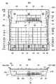
図2(a)は、音響調節器1を斜め上方からみた斜視図、図2(b)は斜め下方からみた斜視図である。図3は、下側ケース30を斜め上方からみた斜視図である。図4(a)は、下側ケース30の平面図、図4(b)は、下側ケース30の正面図、図5(a)は、音響調節器1の後面図、図5(b)は、下側ケース30の後面図である。図6は、図1(a)のA−A線に沿う断面図である。図4(b)、図5(a)、(b)は、厳密には、操作パネル面13を水平にした状態における前面、後面側の図を示している。 FIG. 2A is a perspective view of the
上部ユニット10は、板金またはアルミニウム等で構成される金属製で、図6に示すように、側面視コ字状に形成される。上部ユニット10の水平な上面が操作パネル面13となり、操作パネル面13の前部、後部が、それぞれ下方に屈曲した前面11、後面12となっている(図1(a)、図2、図5(a)、図6参照)。このようなコ字状形成により、上部ユニット10の左右方向における曲げ剛性が高まっている。後面12には、放熱用スリット16が多数形成されている(図5(a)参照)。操作パネル面13には、下側ケース30の後述するネジ14に対応する穴や、各種操作子群47、入出力部46A等(図6参照)を露出させるための穴が対応して形成されている。 The
図3〜図5に示すように、下側ケース30は、前板部54、背板部32、左側板部31L、右側板部31R、及び底板部33を有し、平面視略矩形で皿状に形成される。従って、下側ケース30の上方は開口しており、この開口した部分に、上部ユニット10が装着される。下側ケース30は、合成樹脂で金型により一体成形されてなる。上部ユニット10の前面11と下側ケース30の前板部54とが、音響調節器1のフロント部を構成し、後面12と背板部32とが、音響調節器1のリヤ部を構成する。ただし、このようなフロント部とリヤ部とを上下で分担して構成することは必須ではない。 As shown in FIGS. 3 to 5, the
左側板部31L、右側板部31Rは、前板部54、背板部32よりも少し高くなっている。左側板部31L、右側板部31Rの各上部は、前後方向に沿って左右方向外側にそれぞれ延設されたつば部53L、53Rとなっている。つば部53L、53Rは、ほぼ水平である。つば部53Lの前部、後部は、いずれも、左方に一層張り出して延設されたフランジ部40A、40Bとなっていて、つば部53Rの前部、後部も、右方に一層張り出して延設されたフランジ部40C、40Dとなっている。 The left
各フランジ部40(40A〜40D)には、取付部41及び切り欠き部42がそれぞれ一体に形成されている。つば部53(53L、53R)が前後方向全長に亘って水平に形成されているので、左側板部31L、右側板部31Rの成形後の波打ちや内倒れ等の変形が抑制されるだけでなく、前後方向における曲げ剛性も高まり、ひいては下側ケース30自体の主に前後方向の剛性も高まっている。フランジ部40はラックマウント時のマウント部としての機能を果たし、完成した音響調節器1においては、下側ケース30の取付部41を介して、切り欠き部42を通じてラック51に不図示のネジでネジ止めされることで、音響調節器1がラック51にマウントされる(図1(a)参照)。 Each flange portion 40 (40A to 40D) is integrally formed with a
図2(b)に示すように、底板部33は、前後方向における前端近傍から後半部の途中までが上方に凸となっている凹部38となっている。凹部38は、下側ケース30の左右方向全幅に亘って形成され、据え置き状態において左右の外方に連通している(図1(b)参照)。凹部38は、前側の斜面部38cと、後側の鉛直に近い斜面部38aと、斜面部38a、38cの各上部を結んで延設された水平部38bとで、側面視において凹状形状を形成する(図6参照)。水平部38bは、つば部53と平行であり、上部ユニット10において、水平部38bと操作パネル面13との間隔である厚みは、後部に比し実質的に薄くなっている。凹部38により、下側ケース30の主に左右方向における剛性が高くなっている。斜面部38aと、底板部33のうち斜面部38aに連接する部分にかけて、放熱用スリット39が多数形成されている(図2(b)、図4参照)。 As shown in FIG. 2B, the
図3、図5(b)に示すように、下側ケース30の背板部32の上部には、締結用穴32aが複数形成されている。また、背板部32の上半部且つ右半部には、放熱用スリット49が多数形成されている。 As shown in FIGS. 3 and 5B, a plurality of fastening holes 32 a are formed in the upper portion of the
図3〜図5に示すように、底板部33の上面側には、補強のためのリブや部品取付等のためのボス等の肉部が、多数、下側ケース30と一体に形成されている。例えば、上ケース20を取り付けるためのボス34が、左側板部31L、右側板部31Rに連接して複数形成されると共に、底板部33の前部や中間部分にも複数形成されている。また、後述する操作子基板43(図6参照)等を取り付けるためのボス35も適所に多数形成されている。特に、ボス34、35及び縦型リブ36は、凹部38の水平部38bから上方に突設されている。 As shown in FIGS. 3 to 5, a large number of meat parts such as ribs for reinforcement and bosses for mounting components are integrally formed with the
また、リブについては、例えば、縦型リブ36が、左側板部31L、右側板部31Rに連接して複数形成される。ボス34及び縦型リブ36は、つば部53と同じくらいの高さまで延設されている(図5(b)、図6参照)。 As for the ribs, for example, a plurality of
図6に示すように、下側ケース30の前板部54及び背板部32の各上部に、上部ユニット10の前面11及び後面12の各下部が嵌合された状態で、下側ケース30が上部ユニット10に組み付けられる。すなわち、後方から、ネジ17にて締結用穴32aを介して背板部32と後面12が固定されると共に、上方から、上部ユニット10の操作パネル面13における穴を介して下側ケース30のボス34(図3、図4参照)に対してネジ14(図1参照)が螺合されることで、筐体が構成される。 As shown in FIG. 6, the
下側ケース30における凹部38よりも後方部分には、電源基板45が配設され、電源基板4の上方には入出力端子用基板44が配設される(図4、図6参照)。これらはいずれも操作パネル面13に対して水平に配設され、下側ケース30に対してネジやスナップフィットによって固定される。入出力端子用基板44には、各種端子等を含む入出力部46(46A、46B)が配設乃至接続される。入出力部46Aは、上部ユニット10の操作パネル面13の後部において上方に露出し(図1(a)参照)、入出力部46Bは、下側ケース30の背板部32の左半部において後面側に露出して配設されている(図5(a)参照)。 A
筐体内部において主な熱源となる発熱部品である入出力端子用基板44及び電源基板45は、前後方向における、放熱用スリット39(図2、図4参照)と放熱用スリット16、49(図3、図5参照)との間に位置し、しかも放熱用スリット39、16、49に近接している。そのため、放熱用スリット39、16、49からの放熱効率が高く、基板44、45が効果的に冷却される。しかも、特にラックマウント状態においては、基板44、45に対して、放熱用スリット39が下側、放熱用スリット16、49が上側に位置するので、放熱用スリット39から冷気が流入して、基板44、45を冷却した空気が放熱用スリット16、49から上方に抜けるという、空気の円滑な流れが自然に生じやすく、冷却効果が高い。 The input /
図6に示すように、操作子基板43は、下側ケース30の凹部38の水平部38bにおいて、ボス35(図3、図4参照)に対して水平にネジ止め固定される。操作子基板43には、各種操作子群47が配設され、各種操作子群47は、上部ユニット10の操作パネル面13において上方に露出している(図1(a)参照)。各種操作子群47には、ミキサ装置としての機能設定部品や機能表示部品(スイッチ類、ロータリーボリューム、LEDや液晶表示器等)が含まれる。操作子基板43の前部には、フェーダ装置15が多数配設され、各フェーダ装置15の、操作パネル面13を通じて露出したフェーダ操作子部分に、摘み部15aがそれぞれ嵌装されている(図1、図2等参照)。各基板43、44、45は不図示の束線にて電気的に接続される。なお、各種操作子群47は、下側ケース30ではなく上部ユニット10側に固定して配設してもよい。 As shown in FIG. 6, the
音響調節器1を製造するには、まず、下側ケース30に基板43〜45及び各種内装部品を配設し、下側ケース30の上方が開口した部分に上部ユニット10を装着して螺着固定する。最後に、フェーダ装置15に摘み部15aを取り付ける。 In order to manufacture the
本実施の形態によれば、下側ケース30を樹脂製としたことで、軽量化及び形状の自由化を容易にすることができる。すなわち、金属製では、補強を入れたり逆に軽量化のために肉を削ったりすることが容易でなく、形成の自由度が低いが、樹脂製ではそれらが比較的自由である。従って、本実施の形態では、据え置き使用時においても、違和感のないデザインを採用することが容易である。それでいて、底板部33に凹部38を設けたことで、樹脂製である下側ケース30の高い剛性を確保することができる。 According to the present embodiment, since the
また、下側ケース30は樹脂製であるので、ボスやリブ等の肉部が一体に形成されているが、特に、ボス34、35及び縦型リブ36等の、凹部38の水平部38bに設けられている肉部については、水平部38bが底板部33よりも高いことから、凹部38を設けない場合に比し、それら肉部の高さを低く抑えることが可能となっている。これにより、凹部38を設けることで、音響調節器1自体の薄型化や剛性向上に寄与するだけでなく、肉部の高さを抑えて下側ケース30の成形性を向上させることができる。 Further, since the
また、放熱用スリット39が凹部38に設けられたので、据え置き時において卓面50と放熱用スリット39との間隔を広くできるだけでなく、凹部38は、据え置き状態において左右の外方に連通しているので、筐体内部と外方との空気の連通が円滑である。そのため、据え置き時における筐体内部、特に、放熱用スリット39の近傍に位置する入出力端子用基板44及び電源基板45(図6参照)等の発熱部品の高い冷却性を確保することができる。しかも、ラックマウントされた状態においては、放熱用スリット16、49と放熱用スリット39とが上下の位置関係となって、冷却空気の流れが形成されるので、ラックマウント時における筐体内後部、特に、基板44、45等の発熱部品を効果的に冷却することができる。 In addition, since the
本実施の形態によればまた、下側ケース30の左側板部31L、右側板部31Rに、据え置き状態で前後方向に沿って左右方向外側にそれぞれ張り出したつば部53が突設されたので(図3参照)、樹脂で成形した後における左側板部31L、右側板部31Rの内側方向への倒れや前後方向に沿う波打ち等の変形を抑制することができる。 Further, according to the present embodiment, since the flange portions 53 projecting outward in the left and right direction along the front-rear direction in the stationary state are protruded from the left
しかも、つば部53は、下側ケース30に一体に形成され、つば部53のうちフランジ部40は取付部41(図3、図4(a)参照)を有してラックマウント部を兼ねているので、部品点数を削減すると共に、構成を簡単にし、コストダウンを図ることができる。また、据え置き時とラックマウント時とで、フランジ部40を付け替える等の作業が不要であるので、マウント作業を容易にすることができる。 Moreover, the collar portion 53 is formed integrally with the
また、つば部53が、樹脂製の下側ケース30の剛性を高めているので、下側ケース30に設けられる変形抑制や剛性向上のためのリブの高さや幅を低減することが容易となり、その結果、下側ケース30の容積を有効に利用することができる。 Further, since the collar portion 53 enhances the rigidity of the
なお、発熱部品として入出力端子用基板44及び電源基板45(図6参照)を例示したが、冷却すべき発熱部品はこれらに限られない。また、発熱部品は、下側ケース30に配設されたものに限られず、筐体内部に収容されれば、上部ユニット10に配設されたものであってもよい。 Although the input /
なお、放熱用スリット39と放熱用スリット16、49とが、基板44、45を挟んで前後に設けられたが、前後に限られず、左右あるいは斜めであてもよい。すなわち、本実施の形態では、発熱部品は主に筐体後部にあって、放熱用スリット16、49もリヤ部側に設けられた。しかし、例えば、発熱部品が前部に位置する場合は、放熱用スリットをフロント部側に設けてもよい。また、発熱部品を挟んで放熱用スリット39の反対側に設けられる放熱用スリットは、上部ユニット10または下側ケース30の少なくともいずれかに設けられればよく、本実施の形態の例では、放熱用スリット16、49のいずれか一方であってもよい。 The heat dissipation slit 39 and the heat dissipation slits 16 and 49 are provided on the front and rear sides of the
なお、部品削減及びマウント作業容易化の観点に限って言えば、フランジ部40に代えて、フランジ形状でないマウント部を下側ケース30に一体に設けてもよい。 In terms of reducing parts and facilitating mounting work, a mounting portion that is not flange-shaped may be provided integrally with the
なお、下側ケース30の成形性を向上させるために高さを抑える対象とされる肉部として、ボス34、35及び縦型リブ36を例示したが、これらに限られない。すなわち、補強や取付等のために、鉛直方向成分を含む方向に、凹部38の水平部38bに一体に形成され延設される肉部が対象になるならば、成形性向上の効果は得られる。 In addition, although the
1 音響調節器、 10 上部ユニット、 13 操作パネル面、 30 下側ケース、 31L 左側板部(左側壁部)、 31R 右側板部(右側壁部)、 40A、40B フランジ部(左側フランジ部、マウント部)、 40C、40D フランジ部(右側フランジ部、マウント部)、 51 ラック DESCRIPTION OF
Claims (3)
Translated fromJapanese前記下側ケースは、樹脂で一体に形成され、少なくとも左側壁部と右側壁部とを有して据え置き状態で上方が開口し、
前記上部ユニットは前記下側ケースの前記開口している部分に装着され、
前記下側ケースの前記左側壁部の前部及び後部には、据え置き状態で前後方向に沿って左方向外側にそれぞれ張り出した左前側フランジ部及び左後側フランジ部が前後に分かれて突設され、
前記下側ケースの前記右側壁部の前部及び後部には、据え置き状態で前後方向に沿って右方向外側にそれぞれ張り出した右前側フランジ部及び右後側フランジ部が前後に分かれて突設され、
前記左前側フランジ部、前記左後側フランジ部、前記右前側フランジ部及び前記右後側フランジ部は、前記筐体を前記ラックにマウントするためのマウント部を兼ねていることを特徴とする音響調節器の筐体構造。It has a housing consisting of an upper unit with an operation panel and a lower case, and can be used when the housing is placed on a table, and can also be used when the housing is mounted on a rack. A housing structure of a simple acoustic controller,
The lower case is integrally formed of resin and has at least a left side wall part and a right side wall part, and the upper side is open in a stationary state,
The upper unit is attached to the open part of the lower case,
Collision wherein thefront and rear of the left side wallportion of the lower case, the leftfront side flange portion andthe rear left-side flange portion overhanging respectively tothe left direction outward along the longitudinal direction in a stationary state isdivided into front and rear Established,
On the front and rear of the right side wall of the lower case, a right front flange portion and a right rear flange portion projecting outward in the right direction along the front-rear direction in a stationary state are provided separately in the front-rear direction. ,
The left front flange portion, the left rear flange portion, the right front flange portion, and the right rear flange portion also serve as a mount portion for mounting the housing on the rack. Regulator housing structure.
Priority Applications (4)
| Application Number | Priority Date | Filing Date | Title |
|---|---|---|---|
| JP2007036454AJP5076538B2 (en) | 2007-02-16 | 2007-02-16 | Sound controller housing structure |
| EP08101202AEP1959718A3 (en) | 2007-02-16 | 2008-02-01 | Housing structure of acoustic controller |
| US12/030,319US7733660B2 (en) | 2007-02-16 | 2008-02-13 | Housing structure of acoustic controller |
| CN2008100056374ACN101247704B (en) | 2007-02-16 | 2008-02-14 | Housing structure of acoustic controller |
Applications Claiming Priority (1)
| Application Number | Priority Date | Filing Date | Title |
|---|---|---|---|
| JP2007036454AJP5076538B2 (en) | 2007-02-16 | 2007-02-16 | Sound controller housing structure |
Publications (2)
| Publication Number | Publication Date |
|---|---|
| JP2008205581A JP2008205581A (en) | 2008-09-04 |
| JP5076538B2true JP5076538B2 (en) | 2012-11-21 |
Family
ID=39486637
Family Applications (1)
| Application Number | Title | Priority Date | Filing Date |
|---|---|---|---|
| JP2007036454AExpired - Fee RelatedJP5076538B2 (en) | 2007-02-16 | 2007-02-16 | Sound controller housing structure |
Country Status (4)
| Country | Link |
|---|---|
| US (1) | US7733660B2 (en) |
| EP (1) | EP1959718A3 (en) |
| JP (1) | JP5076538B2 (en) |
| CN (1) | CN101247704B (en) |
Families Citing this family (2)
| Publication number | Priority date | Publication date | Assignee | Title |
|---|---|---|---|---|
| JP6176956B2 (en)* | 2013-03-14 | 2017-08-09 | 発紘電機株式会社 | Programmable display, its manufacturing method, installation method |
| USD969106S1 (en)* | 2020-01-10 | 2022-11-08 | Korg Inc. | Audio mixer |
Family Cites Families (13)
| Publication number | Priority date | Publication date | Assignee | Title |
|---|---|---|---|---|
| JPS58105175U (en)* | 1982-01-13 | 1983-07-18 | 横河電機株式会社 | Instrument mounting structure |
| JPS62192673U (en)* | 1986-05-29 | 1987-12-08 | ||
| US6438241B1 (en)* | 1998-02-23 | 2002-08-20 | Euphonix, Inc. | Multiple driver rotary control for audio processors or other uses |
| JP3915642B2 (en)* | 2002-09-18 | 2007-05-16 | ヤマハ株式会社 | Electronics |
| JP4016775B2 (en)* | 2002-09-19 | 2007-12-05 | ヤマハ株式会社 | Electronic sound equipment |
| JP4232150B2 (en)* | 2003-06-27 | 2009-03-04 | 三菱電機株式会社 | Terminal box |
| CN2657075Y (en)* | 2003-10-25 | 2004-11-17 | 鸿富锦精密工业(深圳)有限公司 | Part receptacle |
| JP4080990B2 (en)* | 2003-11-28 | 2008-04-23 | 株式会社東芝 | Portable electronic device |
| US20050146996A1 (en)* | 2004-01-05 | 2005-07-07 | Numark Industries, Llc | Digital music system for disc jockeys |
| US7118646B2 (en) | 2004-03-15 | 2006-10-10 | Delphi Technologies, Inc. | Method of manufacturing a sealed electronic module |
| US20050259532A1 (en)* | 2004-05-13 | 2005-11-24 | Numark Industries, Llc. | All-in-one disc jockey media player with fixed storage drive and mixer |
| US20070280489A1 (en)* | 2006-03-28 | 2007-12-06 | Numark Industries, Llc | Docking system and mixer for portable media devices with graphical interface |
| JP5082485B2 (en)* | 2007-02-16 | 2012-11-28 | ヤマハ株式会社 | Sound controller housing structure |
- 2007
- 2007-02-16JPJP2007036454Apatent/JP5076538B2/ennot_activeExpired - Fee Related
- 2008
- 2008-02-01EPEP08101202Apatent/EP1959718A3/ennot_activeWithdrawn
- 2008-02-13USUS12/030,319patent/US7733660B2/enactiveActive
- 2008-02-14CNCN2008100056374Apatent/CN101247704B/ennot_activeExpired - Fee Related
Also Published As
| Publication number | Publication date |
|---|---|
| CN101247704A (en) | 2008-08-20 |
| EP1959718A2 (en) | 2008-08-20 |
| EP1959718A3 (en) | 2010-08-18 |
| CN101247704B (en) | 2012-04-04 |
| JP2008205581A (en) | 2008-09-04 |
| US20080197088A1 (en) | 2008-08-21 |
| US7733660B2 (en) | 2010-06-08 |
Similar Documents
| Publication | Publication Date | Title |
|---|---|---|
| JP5159933B1 (en) | TV, electronics | |
| JP4221605B2 (en) | Display panel device | |
| JP5082485B2 (en) | Sound controller housing structure | |
| JP5166581B1 (en) | Electronics | |
| JP2010171226A (en) | Housing structure of acoustic adjusting device | |
| US20090268394A1 (en) | Heat-radiating microcomputer case | |
| WO2020110165A1 (en) | Outdoor unit for air conditioner | |
| JP5076538B2 (en) | Sound controller housing structure | |
| JP2008261508A (en) | Air conditioner electrical component box and air conditioner equipped with the same | |
| US6769748B1 (en) | Electronic device cabinet | |
| JP4792482B2 (en) | Fixing structure between radiator of motor control device and assembly parts | |
| CN112243334B (en) | Heat radiation structure of heating component | |
| JP5050110B2 (en) | Electronics | |
| JP4918413B2 (en) | Refrigerated showcase | |
| US9379831B2 (en) | Acoustic controller | |
| JP5468674B2 (en) | Electronics | |
| JP6282966B2 (en) | Motor control unit | |
| JP4283302B2 (en) | Electronic equipment | |
| JP5740696B2 (en) | Panel cooling system | |
| CN216391871U (en) | Heat dissipation casing, control box and robot | |
| JP2005100312A (en) | Electronics | |
| JP2007041383A (en) | Display device casing and display device | |
| JP6707397B2 (en) | Vehicle switch device | |
| JPH10144067A (en) | Acoustic equipment | |
| JP2007094223A (en) | Display device |
Legal Events
| Date | Code | Title | Description |
|---|---|---|---|
| A621 | Written request for application examination | Free format text:JAPANESE INTERMEDIATE CODE: A621 Effective date:20091215 | |
| A977 | Report on retrieval | Free format text:JAPANESE INTERMEDIATE CODE: A971007 Effective date:20111104 | |
| A131 | Notification of reasons for refusal | Free format text:JAPANESE INTERMEDIATE CODE: A131 Effective date:20111115 | |
| A521 | Written amendment | Free format text:JAPANESE INTERMEDIATE CODE: A523 Effective date:20120116 | |
| TRDD | Decision of grant or rejection written | ||
| A01 | Written decision to grant a patent or to grant a registration (utility model) | Free format text:JAPANESE INTERMEDIATE CODE: A01 Effective date:20120731 | |
| A01 | Written decision to grant a patent or to grant a registration (utility model) | Free format text:JAPANESE INTERMEDIATE CODE: A01 | |
| A61 | First payment of annual fees (during grant procedure) | Free format text:JAPANESE INTERMEDIATE CODE: A61 Effective date:20120813 | |
| FPAY | Renewal fee payment (event date is renewal date of database) | Free format text:PAYMENT UNTIL: 20150907 Year of fee payment:3 | |
| R150 | Certificate of patent or registration of utility model | Free format text:JAPANESE INTERMEDIATE CODE: R150 | |
| LAPS | Cancellation because of no payment of annual fees |