JP5075372B2 - Battery pack - Google Patents
Battery packDownload PDFInfo
- Publication number
- JP5075372B2 JP5075372B2JP2006201496AJP2006201496AJP5075372B2JP 5075372 B2JP5075372 B2JP 5075372B2JP 2006201496 AJP2006201496 AJP 2006201496AJP 2006201496 AJP2006201496 AJP 2006201496AJP 5075372 B2JP5075372 B2JP 5075372B2
- Authority
- JP
- Japan
- Prior art keywords
- temperature
- current
- protection
- battery pack
- battery
- Prior art date
- Legal status (The legal status is an assumption and is not a legal conclusion. Google has not performed a legal analysis and makes no representation as to the accuracy of the status listed.)
- Active
Links
Images


Classifications
- H—ELECTRICITY
- H02—GENERATION; CONVERSION OR DISTRIBUTION OF ELECTRIC POWER
- H02H—EMERGENCY PROTECTIVE CIRCUIT ARRANGEMENTS
- H02H5/00—Emergency protective circuit arrangements for automatic disconnection directly responsive to an undesired change from normal non-electric working conditions with or without subsequent reconnection
- H02H5/04—Emergency protective circuit arrangements for automatic disconnection directly responsive to an undesired change from normal non-electric working conditions with or without subsequent reconnection responsive to abnormal temperature
- H—ELECTRICITY
- H02—GENERATION; CONVERSION OR DISTRIBUTION OF ELECTRIC POWER
- H02H—EMERGENCY PROTECTIVE CIRCUIT ARRANGEMENTS
- H02H7/00—Emergency protective circuit arrangements specially adapted for specific types of electric machines or apparatus or for sectionalised protection of cable or line systems, and effecting automatic switching in the event of an undesired change from normal working conditions
- H02H7/18—Emergency protective circuit arrangements specially adapted for specific types of electric machines or apparatus or for sectionalised protection of cable or line systems, and effecting automatic switching in the event of an undesired change from normal working conditions for batteries; for accumulators
- H—ELECTRICITY
- H02—GENERATION; CONVERSION OR DISTRIBUTION OF ELECTRIC POWER
- H02H—EMERGENCY PROTECTIVE CIRCUIT ARRANGEMENTS
- H02H3/00—Emergency protective circuit arrangements for automatic disconnection directly responsive to an undesired change from normal electric working condition with or without subsequent reconnection ; integrated protection
- H02H3/08—Emergency protective circuit arrangements for automatic disconnection directly responsive to an undesired change from normal electric working condition with or without subsequent reconnection ; integrated protection responsive to excess current
- H—ELECTRICITY
- H02—GENERATION; CONVERSION OR DISTRIBUTION OF ELECTRIC POWER
- H02H—EMERGENCY PROTECTIVE CIRCUIT ARRANGEMENTS
- H02H3/00—Emergency protective circuit arrangements for automatic disconnection directly responsive to an undesired change from normal electric working condition with or without subsequent reconnection ; integrated protection
- H02H3/20—Emergency protective circuit arrangements for automatic disconnection directly responsive to an undesired change from normal electric working condition with or without subsequent reconnection ; integrated protection responsive to excess voltage
Landscapes
- Secondary Cells (AREA)
- Battery Mounting, Suspending (AREA)
- Charge And Discharge Circuits For Batteries Or The Like (AREA)
Description
Translated fromJapanese本発明は、リチウム二次電池などを用いた電池パックに関する。 The present invention relates to a battery pack using a lithium secondary battery or the like.
上記リチウム二次電池を用いた電池パックは、蓄積できる電荷量が多く、パーソナルコンピュータや携帯電話など、消費電力が大きな機器に好適である。しかしながら、それらの機器では、消費電力が大きなアプリケーションの登場や高機能化などに伴い、放電電流を増大することが望まれている。また、充電時間を短縮するために、充電電流の増大の要望が常にある。 A battery pack using the lithium secondary battery has a large amount of charge that can be stored, and is suitable for a device with high power consumption such as a personal computer or a mobile phone. However, in these devices, it is desired to increase the discharge current with the advent of high power consumption applications and higher functionality. In addition, there is always a demand for an increase in charging current in order to shorten the charging time.
そこで、そのような大電流の充放電を行うにあたって、前記大電流に対する温度保護を行う従来技術として、たとえば特許文献1では、電池パックの温度上昇率が規定値以上であると出力制御スイッチをOFFすることで、電池パック側の保護回路を大幅に削減するようにした充電器が提案されている。 Therefore, as a conventional technique for performing temperature protection for the large current when charging and discharging such a large current, for example, in
また、特許文献2では、充放電経路に介在されたスイッチ素子のうち、放電を制御するスイッチ素子のゲート−ソース間にダイオードを設け、そのダイオードの温度が高くなると逆電流が増加する逆方向特性を利用して温度を検出し、前記スイッチ素子が高温になると、ドライブ回路がそのスイッチ素子をOFFして保護動作を行うことで、PTC素子(Positive Temperature Coefficient素子:大電流が流れると抵抗値が急速に大きくなり電流を阻止する素子)等を削減し、安価に温度保護を行うようにした電池パックが提案されている。
しかしながら、いずれの従来技術においても、一定の閾値温度で保護動作を行っているので、FETなどの充放電の電流を制御するスイッチ素子の特性をぎりぎりまで活かし切れているとは言えない。すなわち、前記FETは、図3において参照符号α1で示すように、その時の素子の温度に対して通過電流の許容電流値が変化する。したがって、大きな電流で充放電を行えるように前記閾値温度を高目に設定すると、前記PTC素子などの保護素子の保護動作が先に働いてしまい、電池パックが使えなくなってしまう。このため、あらゆる条件でも保護動作を実現するためには前記閾値温度を低目に設定しなければならず、大電流化の要望には充分に答えられないという問題がある。 However, in any of the prior arts, since the protective operation is performed at a constant threshold temperature, it cannot be said that the characteristics of the switch element that controls the charge / discharge current of the FET or the like are fully utilized. That is, in the FET, as shown by reference numeral α1 in FIG. 3, the allowable current value of the passing current changes with the temperature of the element at that time. Therefore, if the threshold temperature is set high so that charging / discharging can be performed with a large current, the protective operation of the protective element such as the PTC element works first, and the battery pack cannot be used. For this reason, in order to realize the protective operation under all conditions, the threshold temperature must be set to a low value, and there is a problem that it is not possible to sufficiently respond to the demand for a large current.
本発明の目的は、復旧可能な温度保護動作を行うにあたって、充放電電流の増大の要望に応えることができる電池パックを提供することである。 An object of the present invention is to provide a battery pack capable of meeting the demand for an increase in charge / discharge current when performing a recoverable temperature protection operation.
本発明の電池パックは、内蔵電池のセル内またはセルブロック内に、保護素子としてPTC素子を備える電池パックにおいて、前記内蔵電池のセル温度を検出する温度検出手段と、前記温度検出手段によって検出された温度が所定の閾値温度以上となると、内蔵電池への給電経路を復旧可能に遮断する保護手段と、前記給電経路を流れる電流値を検出する電流検出手段と、前記電流検出手段の検出結果に応答し、検出された電流値に適応した前記閾値温度を前記保護手段に設定する設定手段とを含み、前記設定手段は、前記PTC素子の温度に対する電流値の特性に応じて前記閾値温度を設定することを特徴とする。The battery pack of the present invention is a battery packprovided with a PTC element as a protection element in a cell or a cell block of abuilt-in battery, and is detected by the temperature detecting means for detectingthe cell temperature of thebuilt-in battery, and the temperature detecting means. When the detected temperature is equal to or higher than a predetermined threshold temperature, the protection means for reversibly cutting off the power supply path to the internal battery, the current detection means for detecting the current value flowing through the power supply path, and the detection result of the current detection means in response,seen including a setting means for said threshold temperature adapted to the detected current value is set to the protectionmeans, the setting means, the threshold temperature in accordance with the characteristic of the current value with respect to the temperature of the PTC element It is characterizedby setting .
上記の構成によれば、サーミスタなどの温度検出手段によって、セル温度などのパック内の温度を検出し、その検出結果が所定の閾値温度以上となると、保護手段が、内蔵電池への給電経路に介在されるFETをOFFして充放電電流を遮断する等の保護動作を復旧可能に行うようにした電池パックにおいて、本発明では前記閾値温度を可変にし、設定手段が、電流検出手段によって検出されたその時の充放電の電流値に応じて最適な閾値温度を前記保護手段に設定する。前記閾値温度は、内蔵電池のセル内またはセルブロック内に、復帰型保護素子として設けられるPTC素子の温度に対する電流値の特性に応じて設定される。According to the above configuration, the temperature in the pack such as the cell temperature is detected by the temperature detection means such as the thermistor, and when the detection result is equal to or higher than the predetermined threshold temperature, the protection means is connected to the power supply path to the built-in battery. In a battery pack in which a protection operation such as shutting off a charging / discharging current by turning off an intervening FET is made recoverable, in the present invention, the threshold temperature is made variable, and the setting means is detected by the current detection means. An optimum threshold temperature is set in the protection means in accordance with the current value of charging / discharging at that time. The threshold temperature isset according to the characteristic of the current value with respect to the temperature of the PTC element provided as the return type protection element in the cell or cell block of thebuilt-in battery.
前記復帰型保護素子としては、バイメタル素子、PTC素子を挙げることができるが、温度に対する電流値の特性に応じて前記閾値温度を容易に設定できるPTC素子が好適である。そして、本来、外部短絡や異常電流や異常温度に対してはこのPTC素子が作動してパック内が保護されるべきところ、前記設定手段が指数関数的に変化するこのPTC素子の温度に対する電流値の特性に応じて、現在の電流値に適した可能な限り高い閾値温度を調整し、前記PTC素子による保護動作が掛からない範囲で、保護手段が復旧可能に保護動作を行うことで、前記PTC素子による保護動作が掛からない範囲で、可能な限りの電流を流すことができ、異常電流や異常温度で電池パックが使用不能になってしまうことを未然に防止することができる。Thepre-Symbol return type protection device, the bimetal element, there may be mentioneda PTCelement, PTC element that can easily set the threshold temperature in accordance with the characteristics of the current value with respect to temperature is preferred.Then, naturally, the place should the PTCelement against external short circuit or an abnormal current and abnormal temperatureis protected inside the pack operates, the temperature ofthe PT Celement, wherein the setting means changes exponentially By adjusting the threshold temperature as high as possible suitable for the current value according to the characteristic of the current value with respect to the current value, the protection means can perform the protection operation sothat the protection means can be restored within the range where the protection operation by thePTC element is not applied. , to the extent that the protection operation is not applied dueto the PTCelement, it is possible to flow electric current as possible, the battery pack under abnormal current and abnormal temperature can be prevented that becomes unusable .
また、本発明の電池パックでは、前記保護手段および設定手段は、前記内蔵電池への充放電を制御する制御回路に搭載されて保護動作を行い、前記給電経路には温度ヒューズが介在されるとともに、前記制御回路は、前記保護手段を使用した保護動作の失効に対して、異常時の二重保護用に前記温度ヒューズを溶断させることで保護動作を行うことを特徴とする。 In the battery pack of the present invention, the protection means and the setting means are mounted on a control circuit that controls charging / discharging of the built-in battery to perform a protection operation, and a thermal fuse is interposed in the power supply path. The control circuit performs a protection operation by blowing the thermal fuse for double protection at the time of abnormality against the expiration of the protection operation using the protection means.
上記の構成によれば、制御回路の前記保護手段による復旧可能な保護動作に対して、それが失効したときのために、前記給電経路に温度ヒューズが設けられるとともに、そのような異常時の二重保護用に、前記制御回路は、より高い閾値で前記温度ヒューズを溶断させる場合、前記保護手段および設定手段は、その二重保護回路が保護動作を行い、復旧不能になるぎりぎりのレベルまで電流を流すことができ、充放電電流の増大の要望に応えることができる。 According to the above-described configuration, a thermal fuse is provided in the power supply path for when the protection operation that can be restored by the protection means of the control circuit expires. For heavy protection, when the control circuit blows the thermal fuse at a higher threshold, the protection means and the setting means are configured so that the double protection circuit performs a protection operation, and the current is reduced to a level that is impossible to recover. To meet the demand for increased charge / discharge current.
本発明の電池パックは、以上のように、サーミスタなどの温度検出手段によって、セル温度を検出し、その検出結果が所定の閾値温度以上となると、保護手段が、内蔵電池への給電経路に介在されるFETをOFFして充放電電流を遮断する等の保護動作を復旧可能に行うようにした電池パックにおいて、前記閾値温度を可変にし、設定手段が、電流検出手段によって検出されたその時の充放電の電流値に応じて、PTC素子の温度に対する電流値の特性に応じた最適な閾値温度を前記保護手段に設定する。The battery pack of the present invention, as described above, the temperature detecting means such as a thermistor, to detectthe celltemperature, when the detection result is equal to or higher than a predetermined threshold temperature, protection means, the feeding path to the internal battery In the battery pack in which the protection operation such as shutting off the charging / discharging current by turning off the intervening FET is made recoverable, the threshold temperature is made variable, and the setting means at that time detected by the current detection meansAn optimum threshold temperaturecorresponding to the characteristic of the current value with respect to the temperature of the PTC element is set in the protection means according to the charge / discharge current value.
それゆえ、PTC素子による保護動作が掛からない範囲で、可能な限りの電流を流すようにすることができ、充放電電流の増大の要望に応えることができる。Therefore, it is possible to flow as much current as possible within a range where theprotective operation by thePTC element is not applied , and it is possible to meet the demand for an increase in charge / discharge current.
[実施の形態1]
図1は、本発明の実施の一形態に係る充電システムの電気的構成を示すブロック図である。この充電システムは、電池パック1に、それを充電する充電器2を備えて構成されるが、電池パック1から給電が行われる図示しない負荷機器をさらに含めて電子機器システムが構成されてもよい。その場合、電池パック1は、図1では充電器2から充電が行われるけれども、該電池パック1が前記負荷機器に装着されて、負荷機器を通して充電が行われてもよい。電池パック1および充電器2は、給電を行う直流ハイ側の端子T11,T21と、通信信号の端子T12,T22と、給電および通信信号のためのGND端子T13,T23とによって相互に接続される。前記負荷機器が設けられる場合も、同様の端子が設けられる。[Embodiment 1]
FIG. 1 is a block diagram showing an electrical configuration of a charging system according to an embodiment of the present invention. The charging system includes a
前記電池パック1内で、前記の端子T11から延びる直流ハイ側の充放電経路11には、ヒューズ24,25が介在されるとともに、充電用と放電用とで相互に導電形式が異なるFET12,13が介在されており、その充放電経路11が組電池14のハイ側端子に接続される。前記組電池14のロー側端子は、直流ロー側の充放電経路15を介して前記GND端子T13に接続され、この充放電経路15には、充電電流および放電電流を電圧値に変換する電流検出抵抗16が介在されている。 In the
前記組電池14は、複数の二次電池のセルが直並列に接続されて成り、各セルの端子間電圧は電圧検出回路20によって読取られ、マイコン18内のアナログ/デジタル変換器19に入力される。また、前記電流検出抵抗16によって検出された電流値も、前記マイコン18内のアナログ/デジタル変換器19に入力される。前記アナログ/デジタル変換器19は、各入力値をデジタル値に変換して、制御部21へ出力する。 The assembled
制御部21は、マイクロプロセッサおよびその周辺回路などを備えて成り、その充放電制御部21aは、前記アナログ/デジタル変換器19からの各入力値に応答して、充電器2に対して、出力を要求する充電電流の電圧値および電流値を演算し、通信部22から端子T12,T22;T13,T23を介して充電器2へ送信する。 The
また、前記制御部21の安全保護制御部21bは、前記アナログ/デジタル変換器19からの各入力値から、端子T11,T13間の短絡や充電器2からの異常電流などの電池パック1の外部における異常や、組電池14の異常な温度上昇などに対して、前記FET12,13を遮断するなどの保護動作を行う。さらにまた、前記安全保護制御部21bは、セルの異常な過電圧などの深刻な異常時には、前記充放電経路11に直列に介在され、非復帰型保護素子であるヒューズ24,25を溶断する。こうして、セルの過電圧状態に対して、二重の保護系統が設けられていることになる。前記ヒューズ24,25の接続点は、発熱抵抗26およびFET27を介して接地されており、前記安全保護制御部21bがFET27をONすることで、発熱抵抗26が発生した熱で前記ヒューズ24,25が溶断する。 In addition, the safety
なお、前記電圧検出回路20の検出結果を取込む二重保護ICを設け、前記電圧検出回路20の検出結果が予め定める閾値電圧以上となると、前記FET27をONして前記ヒューズ24,25を溶断する別回路を設けることにより、前記制御IC18が故障しても、該制御IC18と別途に設けられるこの二重保護ICによって、セルの過電圧状態に対する信頼性を、より向上させることができる。 A double protection IC for taking in the detection result of the
前記安全保護制御部21bがFET12,13を遮断する通常の充放電時における過電圧の閾値電圧は、たとえばセル当り4.35Vであり、安全保護制御部21bがヒューズ24,25を溶断する閾値電圧は、たとえばセル当り4.45Vであり、通常使用時の過電圧では復旧可能であり、異常時の過電圧では、電池パック1は再使用不能となって安全性の向上が図られている。 The threshold voltage of overvoltage during normal charging / discharging when the safety
そして、前記安全保護制御部21bによってFET27がONされると、発熱抵抗26で発生された熱で、2つのヒューズ24,25は溶断するが、この時、充電状態では、先に組電池14側のヒューズ25が溶断しても、充電器2から充電電流が供給されることで、充電器2側のヒューズ24も後に溶断し、先に充電器2側のヒューズ24が溶断しても、組電池14が前記マイコン18にFET27を駆動する電流を供給できれば組電池14側のヒューズ25も溶断することができ、組電池14が電流を供給できなければ、該組電池14側のヒューズ25は溶断しないままとなるが、前記接続点よりも組電池14側を電池パック1の外部から確実に切り離すことができる。 When the FET 27 is turned on by the safety
これに対して、電池パック1が充電器2にセットされていない放電状態で、組電池14が前記マイコン18にFET27を駆動する電流を供給できれば、先に充電器2側のヒューズ24が溶断しても、後に組電池14側のヒューズ25も溶断し、先に組電池14側のヒューズ25が溶断した場合には充電器2側のヒューズ24は溶断しないままとなるが、前記接続点よりも組電池14側を電池パック1の外部から確実に切り離すことができる。 On the other hand, if the
こうして、相互に直列のヒューズ24,25を用いて、その接続点を発熱抵抗26およびFET27によって接地することで、電池パック1が充電器2にセットされているか否かに拘わらず、前記接続点よりも組電池14側を電池パック1の外部から確実に切り離すことができるようになっている。 In this way, by using the
一方、充電器2では、充放電制御部21aからの前記の要求を制御IC30の通信部32で受信し、充電制御部31が充電電流供給回路33を制御して、前記の電圧値および電流値で、充電電流を供給させる。充電電流供給回路33は、AC−DCコンバータやDC−DCコンバータなどから成り、入力電圧を、前記充電制御部31で指示された電圧値、電流値、およびパルス幅に変換して、端子T21,T11;T23,T13を介して、充放電経路11,16へ供給する。 On the other hand, in the
上述のように構成される充電システムにおいて、注目すべきは、本実施の形態では、前記FET12,13に近接して温度センサ17が設けられており、その検出結果が前記マイコン18内のアナログ/デジタル変換器19から安全保護制御部21bに入力されて該安全保護制御部21bが温度保護動作を行うにあたって、その第1の閾値温度が、設定部21cによって、電流検出抵抗16の検出結果に適応して変化されることである。そして、安全保護制御部21bは、その第1の閾値温度を超えてFET12,13をOFF駆動しても、該FET12,13のON故障などで充放電電流が流れ続ける場合には、前記ヒューズ24,25を溶断する。前記FET12,13を流れる電流の電流値と、FET12,13をOFF駆動する第1の閾値温度との関係は、たとえば表1で示すようであり、前記ヒューズ24,25を溶断する第2の閾値温度は、たとえば前記表1から読取られた温度から5℃高い温度とされる。 In the charging system configured as described above, it should be noted that in the present embodiment, a

図2は、上述のような安全保護制御部21bの動作を説明するためのフローチャートである。この動作は、たとえば2秒毎に行われる。通常の温度保護動作では、ステップS1で、安全保護制御部21bはアナログ/デジタル変換器19の出力から、FET12,13を流れる電流の電流値および温度を読込み、ステップS2で、その電流値に対応した第1の閾値温度が前記設定部21cによって設定される。ステップS3では、温度センサ17による検出結果が前記第1の閾値温度と比較され、該第1の閾値温度以下であるときにはステップS4で前記FET12,13のON状態が継続されて処理を終了する。 FIG. 2 is a flowchart for explaining the operation of the safety
一方、前記ステップS3で、FET12,13の温度が前記第1の閾値温度を超えていると判断されるとステップS5に移り、前記安全保護制御部21bはFET12,13をOFF駆動する。このとき、FET12,13に対して温度センサ17が個別に設けられている場合には、各FET12,13が個別にOFF駆動されてもよい。そして、そのステップS5での保護動作の後、ステップS6ではFET12,13の温度が前記第2の閾値温度と比較され、該第2の閾値温度以上となっている、すなわちFET12,13をOFF駆動する通常の温度保護動作で異常が解消しなかった場合には、前記安全保護制御部21bは、ステップS7でヒューズ24,25を溶断する二重保護動作を行った後、処理を終了する。これに対して、ステップS6でFET12,13の温度が前記第2の閾値温度未満である場合には、そのまま処理を終了する。 On the other hand, if it is determined in step S3 that the temperature of the
なお、前記ステップS5で第1の閾値温度を超えたために復帰可能な保護動作が行われたこと、およびステップS7で第2の閾値温度以上のために復帰不能な二重保護動作が行われたことを、充電時には充電器2へ、放電時には負荷機器3へ、通信部22を介して通知することで、ユーザは、何故電池パック1が使用不能になったのかを認識することができる。 It should be noted that a protection operation that can be restored because the first threshold temperature was exceeded in step S5 was performed, and a double protection operation that could not be restored because the temperature was higher than the second threshold temperature was performed in step S7. This is notified to the
このように構成することで、温度センサ17によってパック内の温度を検出し、安全保護制御部21bがその検出結果に基づいてFET12,13をOFF駆動する温度保護動作を行うにあたって、設定部21cによって前記FET12,13を流れる電流の許容電流値特性に応じて前記第1の閾値温度を設定するので、前記図3において参照符号α1で示すように、その時の素子の温度に対して指数関数的に通過電流の許容電流値が変化しても、前記第1の閾値温度を、参照符号α2で示すように適切に追従して設定することができる。これによって、FET12,13が復旧可能に保護動作を行える範囲で、可能な限りの電流を流すようにすることができ、充放電電流の増大の要望に応えることができる。 With this configuration, the
また、安全保護制御部21bおよび設定部21cを、組電池14への充放電を制御する充放電制御部21aと共にマイコン18に搭載し、前記第1の閾値温度による温度保護動作を行わせる一方、前記マイコン18による前記FET12,13を使用した保護動作の失効に対して、異常時の二重保護用に前記充放電経路11にヒューズ24,25を設け、前記第1の閾値温度よりも高い第2の閾値温度で保護動作を行い、復旧不能になってしまうぎりぎりのレベルまで電流を流すことで、充放電電流の増大の要望に応えることができる。 In addition, the safety
前記第1の閾値温度は、指数関数的に変化する前記FETの温度に対する許容電流値の特性に応じて、前記参照符号α2で示すように段階的に変化されてもよく、テーブルデータや近似演算などの負担が問題にならなければ、前記参照符号α1で示す指数関数の曲線に沿って連続的に変化されてもよい。すなわち、図3において、これら参照符号α1,α2で示す線間の斜線を施して示す領域が、誤動作防止のための不感帯となり、これら参照符号α1,α2で示す線の最近接点が近い程、誤動作の可能性が高くなり、斜線の面積が狭くなる程、多くの電流を流すことができる。したがって、斜線の面積が狭くなるように、かつ最近接点の間隔を離すためには、参照符号α2で示す第1の閾値温度を、参照符号α1で示す許容電流値の特性と平行にすることが望ましい。 The first threshold temperature may be changed in a stepwise manner as indicated by the reference symbol α2 in accordance with the characteristics of the allowable current value with respect to the temperature of the FET that changes exponentially. If such a burden is not a problem, it may be changed continuously along the exponential function curve indicated by the reference symbol α1. That is, in FIG. 3, the hatched area between the lines indicated by the reference characters α1 and α2 is a dead zone for preventing malfunction, and the closer the closest point of the lines indicated by the reference characters α1 and α2 is, the more the malfunction occurs. The higher the possibility, the smaller the hatched area, the more current can flow. Therefore, in order to reduce the area of the hatched line and increase the distance between the closest points, the first threshold temperature indicated by reference symbol α2 should be parallel to the characteristics of the allowable current value indicated by reference symbol α1. desirable.
また、第1の閾値温度を変化する際には、前回の変化方向と同じ(順)方向の変化に対して、逆(戻る)方向の変化がし難くなるヒステリシスを設定することが望ましい。これによって、前記第1の閾値温度の不所望なハンチングを防止することができる。 Further, when changing the first threshold temperature, it is desirable to set a hysteresis that makes it difficult to change in the reverse (return) direction with respect to the change in the same (forward) direction as the previous change direction. Thereby, undesired hunting of the first threshold temperature can be prevented.
[実施の形態2]
図4は、本発明の実施の他の形態に係る充電システムの電気的構成を示すブロック図である。この充電システムは、前述の図1で示す充電システムに類似し、対応する部分には同一の参照符号を付して示し、その説明を省略する。充電器2は、前述の充電システムと同一である。前述の電池パック1では、温度センサ17はFET12,13に近接して設けられており、設定部21cがFET12,13の許容電流値の特性に応じて前記第1の閾値温度を設定していたのに対して、注目すべきは、本実施の形態の電池パック1’では、前記温度センサ17を組電池14に近接して設け、マイコン18’の制御部21’では、設定部21c’における前記第1の閾値温度を、セル内のPTC特性に応じて設定することである。PTC素子は、組電池14のセル内またはセルブロック内に設けられる復帰可能な保護素子で、高温で動作すると高抵抗になり、電流を抑え、電流が下がることで温度が低下してくれば、再度低抵抗状態になり、復帰する。但し、瞬時に復帰しないものもある。[Embodiment 2]
FIG. 4 is a block diagram showing an electrical configuration of a charging system according to another embodiment of the present invention. This charging system is similar to the charging system shown in FIG. 1 described above, and corresponding portions are denoted by the same reference numerals and description thereof is omitted. The
この場合にFET12,13をOFF駆動する第1の閾値温度と、セルを流れる充放電電流との関係は、たとえば表2で示すようであり、前記ヒューズ24,25を溶断する第2の閾値温度は、たとえば85℃に設定される。 In this case, the relationship between the first threshold temperature for driving the
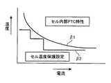
このように構成することで、本来、異常電流や異常温度に対してはこのPTC素子が作動してパック内が保護されるべきところ、温度センサ17によってパック内の温度を検出し、安全保護制御部21b’がその検出結果に基づいてFET12,13をOFF駆動することで、PTC素子が作動する前の段階で復旧可能な温度保護動作を行うことができる。また、設定部21c’によってセル内のPTC素子の温度に対する電流値の特性に応じて前記第1の閾値温度を設定するので、図5において参照符号β1で示すように、その時のセルの温度に対して指数関数的に電流が絞られても、前記第1の閾値温度を、参照符号β2で示すように適切に追従して設定することができる。これによって、前記PTC素子による保護動作が掛からない範囲で、可能な限りの電流を流すことができ、前記異常電流や異常温度で電池パックが使用不能になってしまうことを未然に防止することができる。 With this configuration, the PTC element should normally be activated against abnormal current and abnormal temperature to protect the inside of the pack. However, the temperature in the pack is detected by the
本発明の電池パックは、サーミスタなどの温度センサ17によって、セル温度などのパック内の温度を検出し、その検出結果が所定の閾値温度以上となると、マイコン18内の安全保護制御部21bが、組電池14への充放電経路11に介在されるFET12,13をOFFして充放電電流を遮断する等の保護動作を復旧可能に行うようにした電池パックにおいて、前記閾値温度を可変にし、設定部21cが、電流検出抵抗16によって検出されたその時の充放電の電流値に応じて最適な閾値温度を前記安全保護制御部21bに設定するので、FET12,13が復旧可能に保護動作を行える範囲で、可能な限りの電流を流すようにすることができ、近年の大きな充放電電流の要求される電池パックに好適である。 The battery pack of the present invention detects the temperature in the pack such as the cell temperature by the
1,1’ 電池パック
2 充電器
11,15 充放電経路(給電経路)
12,13 FET(保護手段)
14 組電池(内蔵電池)
16 電流検出抵抗(電流検出手段)
17 温度センサ(温度検出手段)
18,18’ マイコン(制御回路)
19 アナログ/デジタル変換器
20 電圧検出回路
21,21’ 制御部
21a 充放電制御部
21b,21b’ 安全保護制御部(保護手段)
21c,21c’ 設定部(設定手段)
22,32 通信部
24,25 ヒューズ
26 発熱抵抗
27 FET
30 制御IC
31 充電制御部
33 充電電流供給回路
T11,T21;T12,T22;T13,T23;T14,T24 端子1,1 '
12, 13 FET (protection means)
14 Battery pack (built-in battery)
16 Current detection resistor (current detection means)
17 Temperature sensor (temperature detection means)
18, 18 'microcomputer (control circuit)
19 Analog /
21c, 21c ′ setting section (setting means)
22, 32
30 Control IC
31 charging
Claims (2)
Translated fromJapanese前記内蔵電池のセル温度を検出する温度検出手段と、
前記温度検出手段によって検出された温度が所定の閾値温度以上となると、内蔵電池への給電経路を復旧可能に遮断する保護手段と、
前記給電経路を流れる電流値を検出する電流検出手段と、
前記電流検出手段の検出結果に応答し、検出された電流値に適応した前記閾値温度を前記保護手段に設定する設定手段とを含み、
前記設定手段は、前記PTC素子の温度に対する電流値の特性に応じて前記閾値温度を設定することを特徴とする電池パック。In a battery pack including aPTC element as a protective element in a cell or cell block of a built-in battery ,
Temperature detecting means for detectingthe cell temperature of theinternal battery ;
When the temperature detected by the temperature detection means is equal to or higher than a predetermined threshold temperature, protection means for reversibly cutting off the power supply path to the built-in battery;
Current detection means for detecting a current value flowing through the power supply path;
Wherein in response to the detection result of the current detecting means,seen including a setting means for said threshold temperature adapted to the detected current value is set to the protectionmeans,
The battery pack, wherein the setting means sets the threshold temperature according to a characteristic of a current value with respect to a temperature of the PTC element .
前記給電経路には温度ヒューズが介在されるとともに、前記制御回路は、前記保護手段を使用した保護動作の失効に対して、異常時の二重保護用に前記温度ヒューズを溶断させることで保護動作を行うことを特徴とする請求項1記載の電池パック。The protection means and the setting means are mounted on a control circuit that controls charging / discharging to the built-in battery and perform a protection operation,
A thermal fuse is interposed in the power supply path, and the control circuit protects against invalidation of the protective operation using the protective means by blowing the thermal fuse for double protection at the time of abnormality. The battery pack according to claim1, wherein:
Priority Applications (1)
| Application Number | Priority Date | Filing Date | Title |
|---|---|---|---|
| JP2006201496AJP5075372B2 (en) | 2006-07-25 | 2006-07-25 | Battery pack |
Applications Claiming Priority (1)
| Application Number | Priority Date | Filing Date | Title |
|---|---|---|---|
| JP2006201496AJP5075372B2 (en) | 2006-07-25 | 2006-07-25 | Battery pack |
Publications (2)
| Publication Number | Publication Date |
|---|---|
| JP2008027826A JP2008027826A (en) | 2008-02-07 |
| JP5075372B2true JP5075372B2 (en) | 2012-11-21 |
Family
ID=39118237
Family Applications (1)
| Application Number | Title | Priority Date | Filing Date |
|---|---|---|---|
| JP2006201496AActiveJP5075372B2 (en) | 2006-07-25 | 2006-07-25 | Battery pack |
Country Status (1)
| Country | Link |
|---|---|
| JP (1) | JP5075372B2 (en) |
Families Citing this family (23)
| Publication number | Priority date | Publication date | Assignee | Title |
|---|---|---|---|---|
| JP4912108B2 (en)* | 2006-10-11 | 2012-04-11 | 三洋電機株式会社 | Discharge control device and charge control device |
| JP2010061970A (en)* | 2008-09-03 | 2010-03-18 | Panasonic Corp | Charge system, and charging method for secondary battery |
| EP2342791A4 (en)* | 2008-10-02 | 2012-12-12 | Leyden Energy Inc | Electronic current interrupt device for battery |
| JP2010115047A (en)* | 2008-11-07 | 2010-05-20 | Hitachi Koki Co Ltd | Charger |
| JP5064452B2 (en)* | 2009-07-31 | 2012-10-31 | パナソニック株式会社 | Protection circuit and battery pack |
| CN102273044B (en)* | 2009-07-31 | 2015-04-22 | 松下电器产业株式会社 | Protection circuit, battery pack, and charging system |
| JP5064455B2 (en)* | 2009-08-20 | 2012-10-31 | パナソニック株式会社 | Protection circuit, battery pack, and charging system |
| JP5275176B2 (en)* | 2009-08-31 | 2013-08-28 | レノボ・シンガポール・プライベート・リミテッド | Battery pack and its function stop method |
| JP5045849B2 (en)* | 2009-09-02 | 2012-10-10 | トヨタ自動車株式会社 | Sulfide all solid lithium secondary battery system |
| JP5454043B2 (en)* | 2009-09-24 | 2014-03-26 | 日本電気株式会社 | Charge control circuit and charge control method |
| JP2014513512A (en)* | 2011-04-28 | 2014-05-29 | ゾール サーキュレイション インコーポレイテッド | Battery management system for control of lithium power cell |
| US10862323B2 (en) | 2011-04-28 | 2020-12-08 | Zoll Circulation, Inc. | Battery management system for control of lithium power cells |
| WO2013022053A1 (en)* | 2011-08-09 | 2013-02-14 | 三洋電機株式会社 | Power control device |
| US9362750B2 (en)* | 2011-12-05 | 2016-06-07 | Samsung Sdi Co., Ltd. | Energy storage system and method for controlling the same |
| JP6105276B2 (en)* | 2012-12-25 | 2017-03-29 | カルソニックカンセイ株式会社 | Vehicle safety device |
| JP6278687B2 (en)* | 2013-12-18 | 2018-02-14 | キヤノン株式会社 | Electronic device, method and program |
| JP6385310B2 (en)* | 2015-04-21 | 2018-09-05 | エイブリック株式会社 | Battery device |
| KR102412313B1 (en)* | 2018-07-17 | 2022-06-22 | 주식회사 엘지에너지솔루션 | Apparatus and method for diagnosing switch |
| JP7131211B2 (en)* | 2018-08-30 | 2022-09-06 | 株式会社オートネットワーク技術研究所 | Power supply controller |
| KR102390002B1 (en)* | 2018-08-31 | 2022-04-22 | 주식회사 엘지에너지솔루션 | System and method for controlling a fuse using detecting a failure mode |
| CN111106595B (en)* | 2018-10-26 | 2023-11-21 | 中兴通讯股份有限公司 | Over-temperature protection circuit, method and system of power supply |
| JP7211761B2 (en)* | 2018-10-26 | 2023-01-24 | 三菱重工メイキエンジン株式会社 | engine starter and battery |
| WO2024257671A1 (en)* | 2023-06-15 | 2024-12-19 | パナソニックIpマネジメント株式会社 | Battery protection device and battery pack |
Family Cites Families (2)
| Publication number | Priority date | Publication date | Assignee | Title |
|---|---|---|---|---|
| JPH04113664A (en)* | 1990-09-03 | 1992-04-15 | Mitsubishi Electric Corp | Semiconductor integrated circuit |
| JP4367266B2 (en)* | 2004-07-13 | 2009-11-18 | 株式会社村田製作所 | Battery pack protection circuit |
- 2006
- 2006-07-25JPJP2006201496Apatent/JP5075372B2/enactiveActive
Also Published As
| Publication number | Publication date |
|---|---|
| JP2008027826A (en) | 2008-02-07 |
Similar Documents
| Publication | Publication Date | Title |
|---|---|---|
| JP5075372B2 (en) | Battery pack | |
| US7391185B2 (en) | Battery pack protection circuit with plural protective means, and battery pack including the protection circuit | |
| JP5053337B2 (en) | Protection element and protection system for storage battery | |
| JP4936227B2 (en) | Battery pack and electric tool using the battery pack | |
| JP4791995B2 (en) | Battery pack | |
| JP2005317510A (en) | Power supply device | |
| US9270106B2 (en) | Temperature protection device of electronic device | |
| KR20210046543A (en) | Secondary battery protection circuit, secondary battery protection device, battery pack and temperature detecting circuit | |
| JP4852300B2 (en) | Battery pack | |
| CN1965457B (en) | protection circuit of battery pack and battery pack | |
| JP5064776B2 (en) | Pack battery | |
| KR20140143874A (en) | Unexpected temperature detecting apparatus using shunt regulator and battery system comprising the same | |
| CN111799860A (en) | Electrochemical device and power supply control method | |
| JP6955951B2 (en) | Discharge device | |
| JP2006121827A (en) | Protection circuit for secondary battery | |
| JP4449885B2 (en) | Secondary battery protection device | |
| JP7307156B2 (en) | Electrochemical device, electrical equipment, electric vehicle, and power supply control method | |
| JP2005312140A (en) | Charge / discharge control circuit | |
| KR102065735B1 (en) | Apparatus and method for managing battery pack | |
| JP4536040B2 (en) | Electrical equipment | |
| JP2008046719A (en) | Integrated circuit incorporating power source | |
| JP4367266B2 (en) | Battery pack protection circuit | |
| JP2013165631A (en) | Switching circuit and battery pack | |
| JP6707956B2 (en) | Charge/discharge protection system and rechargeable vacuum cleaner | |
| JP5157091B2 (en) | Semiconductor protection circuit device |
Legal Events
| Date | Code | Title | Description |
|---|---|---|---|
| A621 | Written request for application examination | Free format text:JAPANESE INTERMEDIATE CODE: A621 Effective date:20090715 | |
| A131 | Notification of reasons for refusal | Free format text:JAPANESE INTERMEDIATE CODE: A131 Effective date:20120124 | |
| A521 | Request for written amendment filed | Free format text:JAPANESE INTERMEDIATE CODE: A523 Effective date:20120314 | |
| TRDD | Decision of grant or rejection written | ||
| A01 | Written decision to grant a patent or to grant a registration (utility model) | Free format text:JAPANESE INTERMEDIATE CODE: A01 Effective date:20120821 | |
| A01 | Written decision to grant a patent or to grant a registration (utility model) | Free format text:JAPANESE INTERMEDIATE CODE: A01 | |
| A61 | First payment of annual fees (during grant procedure) | Free format text:JAPANESE INTERMEDIATE CODE: A61 Effective date:20120827 | |
| R150 | Certificate of patent or registration of utility model | Ref document number:5075372 Country of ref document:JP Free format text:JAPANESE INTERMEDIATE CODE: R150 Free format text:JAPANESE INTERMEDIATE CODE: R150 | |
| FPAY | Renewal fee payment (event date is renewal date of database) | Free format text:PAYMENT UNTIL: 20150831 Year of fee payment:3 |