JP5074944B2 - Display control apparatus and display control program having remote control function - Google Patents
Display control apparatus and display control program having remote control functionDownload PDFInfo
- Publication number
- JP5074944B2 JP5074944B2JP2008025353AJP2008025353AJP5074944B2JP 5074944 B2JP5074944 B2JP 5074944B2JP 2008025353 AJP2008025353 AJP 2008025353AJP 2008025353 AJP2008025353 AJP 2008025353AJP 5074944 B2JP5074944 B2JP 5074944B2
- Authority
- JP
- Japan
- Prior art keywords
- signal
- video
- display
- signal pattern
- television
- Prior art date
- Legal status (The legal status is an assumption and is not a legal conclusion. Google has not performed a legal analysis and makes no representation as to the accuracy of the status listed.)
- Active
Links
Images


Classifications
- H—ELECTRICITY
- H04—ELECTRIC COMMUNICATION TECHNIQUE
- H04N—PICTORIAL COMMUNICATION, e.g. TELEVISION
- H04N21/00—Selective content distribution, e.g. interactive television or video on demand [VOD]
- H04N21/40—Client devices specifically adapted for the reception of or interaction with content, e.g. set-top-box [STB]; Operations thereof
- H04N21/41—Structure of client; Structure of client peripherals
- H04N21/422—Input-only peripherals, i.e. input devices connected to specially adapted client devices, e.g. global positioning system [GPS]
- H04N21/42204—User interfaces specially adapted for controlling a client device through a remote control device; Remote control devices therefor
- H04N21/42206—User interfaces specially adapted for controlling a client device through a remote control device; Remote control devices therefor characterized by hardware details
- H—ELECTRICITY
- H04—ELECTRIC COMMUNICATION TECHNIQUE
- H04N—PICTORIAL COMMUNICATION, e.g. TELEVISION
- H04N21/00—Selective content distribution, e.g. interactive television or video on demand [VOD]
- H04N21/40—Client devices specifically adapted for the reception of or interaction with content, e.g. set-top-box [STB]; Operations thereof
- H04N21/47—End-user applications
- H04N21/485—End-user interface for client configuration
Landscapes
- Engineering & Computer Science (AREA)
- Multimedia (AREA)
- Signal Processing (AREA)
- Human Computer Interaction (AREA)
- Controls And Circuits For Display Device (AREA)
- Details Of Television Systems (AREA)
- Two-Way Televisions, Distribution Of Moving Picture Or The Like (AREA)
Abstract
Description
Translated fromJapanese本発明は、遠隔制御機能を備えた表示制御装置および当該装置で実行される表示制御プログラムに関し、より特定的には、遠隔制御可能なテレビジョン受像器等に対して遠隔制御可能な遠隔制御機能を備えたゲーム装置等の表示制御装置および当該装置で実行される表示制御プログラムに関する。 The present invention relates to a display control device having a remote control function and a display control program executed by the device, and more specifically, a remote control function capable of remote control with respect to a remotely controllable television receiver or the like. The present invention relates to a display control device such as a game device provided with a display control program executed by the device.
従来、テレビジョン受像器に接続され、その内部で映像音声信号を処理してテレビジョン受像器に出力する映像音声信号処理装置がある(例えば、特許文献1参照)。上記特許文献1には、遠隔操作機器(リモート・コントローラ;以下リモコンと記載する)とテレビジョン受像器に接続されるハードディスク・レコーダとを有する映像音声処理装置が開示されている。上記テレビジョン受像器は、地上波チューナおよびBSチューナが内蔵されている。そして、ハードディスク・レコーダから出力される映像音声信号は、テレビジョン受像器に設けられた外部接続端子を経由して当該テレビジョン受像器に入力される。また、リモコンは、テレビジョン受像器のリモコン受信部およびハードディスク・レコーダのリモコン受信部に向けて制御信号を発信して、視聴する放送チャンネルの切り換えや外部機器からの外部入力信号の切り換え等を行う。
上記特許文献1で開示された映像音声信号処理装置は、ユーザがリモコンのボタンを操作することによって、テレビジョン受像器で視聴する信号を切り換えている。例えば、映像音声信号処理装置は、テレビジョン受像器に内蔵されている地上波チューナが受信した地上波放送信号と、ハードディスク・レコーダから外部接続端子を経由してテレビジョン受像器に入力される映像音声信号とのいずれを、テレビジョン受像器に出力させるかについて、リモコンからの信号に応じて切り換える。 The video / audio signal processing apparatus disclosed in
ここで、テレビジョン受像器で地上波放送信号による映像音声を視聴している場合は、ハードディスク・レコーダからの映像音声信号による映像音声がテレビジョン受像器から出力されない。したがって、テレビジョン受像器内蔵チューナで受信した信号に基づいた映像音声を視聴中に、ハードディスク・レコーダからユーザに向けて発する必要のある情報があった場合、当該情報を報知することができない。また、ハードディスク・レコーダからの映像音声信号による映像音声が、接続不良等によってテレビジョン受像器で正常に視聴できない場合、テレビジョン受像器から何の情報も報知されないためにユーザに異常であることやその処置方法等を報知することができない。 Here, when the video / audio by the terrestrial broadcast signal is viewed on the television receiver, the video / audio by the video / audio signal from the hard disk recorder is not output from the television receiver. Therefore, when there is information that needs to be emitted from the hard disk recorder to the user while viewing the video and audio based on the signal received by the tuner with a built-in television receiver, the information cannot be notified. In addition, when the video / audio by the video / audio signal from the hard disk recorder cannot be normally viewed on the television receiver due to poor connection or the like, it is abnormal to the user because no information is notified from the television receiver. The treatment method cannot be notified.
それ故に、本発明の目的は、2つの映像音声信号による映像音声の何れかを選択的にテレビジョン受像器等の表示装置に表示出力する場合に、選択された映像音声信号に応じた情報を当該表示装置とは別の機器から報知することのできる表示制御装置および当該装置で実行される表示制御プログラムを提供することである。 Therefore, the object of the present invention is to display information corresponding to the selected video / audio signal when selectively outputting either of the video / audio by the two video / audio signals to a display device such as a television receiver. It is to provide a display control device that can be notified from a device different from the display device and a display control program that is executed by the device.
上記の目的を達成するために、本発明は以下の構成を採用した。なお、括弧内の参照符号、ステップ番号、図面番号等は、本発明の理解を助けるために後述する最良の形態との対応関係を示したものであって、本発明の範囲を何ら限定するものではない。 In order to achieve the above object, the present invention employs the following configuration. Reference numerals, step numbers, drawing numbers and the like in parentheses indicate correspondence with the best mode to be described later in order to help understanding of the present invention, and limit the scope of the present invention. is not.
第1の発明は、無線通信を用いて遠隔操作可能な表示装置(2)に接続される表示制御装置(3)である。表示制御装置は、第1映像音声信号生成手段(ステップ52、81、82を実行するCPU10;以下、単にステップ番号のみ記載する)、信号パターン記憶手段(12、35、Db1)、選択手段(S55、S58、S84、S92)、無線出力手段(8)、および報知手段(706)を備える。第1映像音声信号生成手段は、表示装置に第1画像(図12〜図16、図23)を表示するための第1映像音声信号を生成して、表示装置へ出力する。信号パターン記憶手段は、第1映像音声信号に基づいた第1画像を表示装置に表示させる命令を示す第1信号パターン(外部入力切換信号の信号パターン)および表示制御装置とは別の機器(45)から得られた第2映像音声信号に基づいた第2画像を表示装置に表示させる命令を示す第2信号パターン(放送チャンネル信号の信号パターン)を記憶する。選択手段は、第1信号パターンおよび第2信号パターンの何れか一方を選択する。無線出力手段は、無線通信を用いて、選択手段が選択した信号パターンの無線信号を表示装置に出力する。報知手段は、無線出力手段によって出力された無線信号の信号パターンに応じて、当該信号パターンにしたがって決められる情報(メッセージ1〜3)を表示装置とは別の装置(706)から報知する。 1st invention is the display control apparatus (3) connected to the display apparatus (2) which can be operated remotely using wireless communication. The display control apparatus includes first video / audio signal generation means (
第2の発明は、上記第1の発明において、入力装置(7)および入力データ取得手段(S53、S57、S83、S87、S88、S95、S98)を、さらに備える。入力装置は、ユーザからの入力を受け付けてユーザ入力データ(Da)を出力する。入力データ取得手段は、入力装置からユーザ入力データを取得する。報知手段は、入力装置に設けられる。選択手段は、入力データ取得手段が取得したユーザ入力データに応じて、第1信号パターンおよび第2信号パターンの何れか一方を選択する。 The second invention further includes an input device (7) and input data acquisition means (S53, S57, S83, S87, S88, S95, S98) in the first invention. The input device receives input from the user and outputs user input data (Da). The input data acquisition unit acquires user input data from the input device. The notification means is provided in the input device. The selection unit selects either the first signal pattern or the second signal pattern according to the user input data acquired by the input data acquisition unit.
第3の発明は、上記第1または第2の発明において、報知手段は、情報を音声で出力して報知する。 In a third aspect based on the first aspect or the second aspect, the notifying means outputs the information by voice and notifies it.
第4の発明は、上記第1または第2の発明において、情報記憶手段(12、35、Db2)を、さらに備える。情報記憶手段は、信号パターンにしたがって決められる情報を予め複数記憶する。報知手段は、無線出力手段によって出力された無線信号の信号パターンに応じて、情報記憶手段に記憶されている複数の情報から選択し、選択された情報を報知する。 According to a fourth invention, in the first or second invention, the information storage means (12, 35, Db2) is further provided. The information storage means stores in advance a plurality of information determined according to the signal pattern. The notification means selects from the plurality of information stored in the information storage means according to the signal pattern of the wireless signal output by the wireless output means, and notifies the selected information.
第5の発明は、上記第4の発明において、報知手段は、第1信号パターンの無線信号が出力された場合、第1映像音声信号に関する情報(メッセージ3)を報知する。報知手段は、第2信号パターンの無線信号が出力された場合、第2映像音声信号に関する情報(メッセージ1)を報知する。 In a fifth aspect based on the fourth aspect, when the wireless signal having the first signal pattern is output, the notification means notifies information (message 3) relating to the first video / audio signal. When the wireless signal having the second signal pattern is output, the notification unit notifies information (message 1) related to the second video / audio signal.
第6の発明は、上記第4の発明において、報知手段は、第1信号パターンの無線信号が出力された場合、表示装置に第1画像が表示されているか否かの確認を促す情報(メッセージ3)を報知する。報知手段は、第2信号パターンの無線信号が出力された場合、表示装置に第2画像が表示されているか否かの確認を促す情報(メッセージ1)を報知する。 In a sixth aspect based on the fourth aspect, when the radio signal having the first signal pattern is output, the notification means prompts to confirm whether or not the first image is displayed on the display device (message 3) is notified. When the wireless signal having the second signal pattern is output, the notification unit notifies information (message 1) that prompts confirmation of whether or not the second image is displayed on the display device.
第7の発明は、上記第2の発明において、報知手段は、第1信号パターンの無線信号が出力された場合、表示装置に第1画像が表示されているか否かを確認し、その確認結果を入力装置に入力するように促す情報(メッセージ3)を報知する。報知手段は、第2信号パターンの無線信号が出力された場合、表示装置に第2画像が表示されているか否かを確認し、その確認結果を入力装置に入力するように促す情報(メッセージ1)を報知する。 In a seventh aspect based on the second aspect, the notification means confirms whether or not the first image is displayed on the display device when the wireless signal of the first signal pattern is output, and the confirmation result Is notified to the input device (message 3). The notification means confirms whether or not the second image is displayed on the display device when the wireless signal of the second signal pattern is output, and information (message 1) prompting the input of the confirmation result to the input device. ).
第8の発明は、上記第7の発明において、報知手段は、第1画像または第2画像が表示されていないとする確認結果を示すユーザ入力データが入力データ取得手段で取得された場合(S88でYes、S98およびS99でYes)、表示装置と表示制御装置との間の遠隔操作ができないことを示す情報(メッセージ2)を、さらに報知する。 In an eighth aspect based on the seventh aspect, the notification means obtains user input data indicating a confirmation result indicating that the first image or the second image is not displayed by the input data obtaining means (S88). If yes, Yes in S98 and S99), information (message 2) indicating that the remote control between the display device and the display control device cannot be performed is further notified.
第9の発明は、上記第2の発明において、表示装置は、複数の外部入力端子(47)およびチューナ(45)を含む。複数の外部入力端子は、外部から映像音声信号が入力される。チューナは、放送局からのテレビジョン信号を受信して第2映像音声信号を生成する。表示制御装置は、複数の外部入力端子の何れか1つと接続される。第1信号パターンは、複数の外部入力端子に入力されたそれぞれの映像音声信号に基づいた第1画像を表示装置に表示させる命令を示し、外部入力端子毎に対応して異なる複数の信号パターンをそれぞれ有する(図18)。選択手段は、第1信号パターンを選択する場合、複数の信号パターンから外部入力端子毎に順次異なる信号パターンを選択する(S92、S93、S101)。報知手段は、第1信号パターンの無線信号が出力された場合、表示装置に第1画像が表示されているか否かを確認し、その確認結果を入力装置に入力するように促す情報(メッセージ3)を報知する。表示制御装置は、第1信号パターン特定手段(S96、Db4)を、さらに備える。第1信号パターン特定手段は、入力データ取得手段が取得したユーザ入力データに基づいて(S95でYes)、表示装置に接続されている当該表示制御装置の外部入力端子に対応する信号パターンを複数の信号パターンから特定する。 In a ninth aspect based on the second aspect, the display device includes a plurality of external input terminals (47) and a tuner (45). A plurality of external input terminals receive video / audio signals from outside. The tuner receives a television signal from a broadcasting station and generates a second video / audio signal. The display control device is connected to any one of a plurality of external input terminals. The first signal pattern indicates a command for causing the display device to display a first image based on the respective video / audio signals input to the plurality of external input terminals, and a plurality of different signal patterns corresponding to the respective external input terminals are displayed. Each has (FIG. 18). When selecting the first signal pattern, the selecting means sequentially selects different signal patterns for each external input terminal from the plurality of signal patterns (S92, S93, S101). The notification means confirms whether or not the first image is displayed on the display device when the wireless signal of the first signal pattern is output, and information (message 3) that prompts the user to input the confirmation result to the input device. ). The display control device further includes first signal pattern specifying means (S96, Db4). Based on the user input data acquired by the input data acquisition unit (Yes in S95), the first signal pattern specifying unit sets a plurality of signal patterns corresponding to the external input terminals of the display control device connected to the display device. Specify from signal pattern.
第10の発明は、上記第1または第2の発明において、表示装置は、外部入力端子およびチューナを含む。外部入力端子は、外部から映像音声信号が入力される。チューナは、放送局からのテレビジョン信号を受信して第2映像音声信号を生成する。表示制御装置は、外部入力端子と接続されて第1映像音声信号を出力する。第1信号パターンは、外部入力端子に入力された第1映像音声信号に基づいた第1画像を表示装置に表示させる命令を示す。第2信号パターンは、チューナがテレビジョン信号を受信して生成する第2映像音声信号に基づいた第2画像を表示装置に表示させる命令を示す。報知手段は、第1信号パターンの無線信号が出力された場合、表示装置に第1画像が表示されているか否かの確認を促す情報を報知する。報知手段は、第2信号パターンの無線信号が出力された場合、表示装置に第2画像が表示されているか否かを確認を促す情報を報知する。 In a tenth aspect based on the first or second aspect, the display device includes an external input terminal and a tuner. A video / audio signal is input to the external input terminal from the outside. The tuner receives a television signal from a broadcasting station and generates a second video / audio signal. The display control device is connected to the external input terminal and outputs the first video / audio signal. The first signal pattern indicates a command for causing the display device to display a first image based on the first video / audio signal input to the external input terminal. The second signal pattern indicates a command for causing the display device to display a second image based on a second video / audio signal generated by receiving a television signal by the tuner. When the wireless signal having the first signal pattern is output, the notifying unit notifies information prompting confirmation of whether or not the first image is displayed on the display device. When the wireless signal having the second signal pattern is output, the notification unit notifies information for prompting confirmation as to whether or not the second image is displayed on the display device.
第11の発明は、上記第1または第2の発明において、表示装置は、複数の外部入力端子を含む。複数の外部入力端子は、外部から映像音声信号が入力される。複数の外部入力端子は、第2映像音声信号を出力する機器および表示制御装置がそれぞれ別の端子に接続される。第1信号パターンは、外部入力端子を介して表示制御装置から出力された第1映像音声信号に基づいた第1画像を表示装置に表示させる命令を示す。第2信号パターンは、外部入力端子を介して機器から出力された第2映像音声信号に基づいた第2画像を表示装置に表示させる命令を示す。報知手段は、第1信号パターンの無線信号が出力された場合、表示装置に第1画像が表示されているか否かの確認を促す情報を報知する。報知手段は、第2信号パターンの無線信号が出力された場合、表示装置に第2画像が表示されているか否かを確認を促す情報を報知する。 In an eleventh aspect based on the first or second aspect, the display device includes a plurality of external input terminals. A plurality of external input terminals receive video / audio signals from outside. The plurality of external input terminals are connected to different terminals for the device that outputs the second video / audio signal and the display control device. The first signal pattern indicates a command for causing the display device to display a first image based on the first video / audio signal output from the display control device via the external input terminal. The second signal pattern indicates a command for causing the display device to display a second image based on the second video / audio signal output from the device via the external input terminal. When the wireless signal having the first signal pattern is output, the notifying unit notifies information prompting confirmation of whether or not the first image is displayed on the display device. When the wireless signal having the second signal pattern is output, the notification unit notifies information for prompting confirmation as to whether or not the second image is displayed on the display device.
第12の発明は、上記第2の発明において、入力装置は、ポインティング手段(74)および複数のボタン(72)を有する。ポインティング手段は、表示装置に出力された第1画像に対する任意の位置が指示可能であり、当該位置を得るための位置データ(Da1、Da2)をユーザ入力データとして出力する。複数のボタンは、ユーザの押下によって操作され、その操作結果を示すキーデータ(Da3)をユーザ入力データとして出力する。表示制御装置は、指示位置算出手段(S53)を、さらに備える。指示位置算出手段は、入力データ取得手段が取得した位置データに基づいて、第1画像に対する指示位置を算出する。選択手段は、指示位置算出手段が算出した指示位置が第1画像における所定領域の場合(S53でYes)、第2信号パターンを選択する。選択手段は、入力データ取得手段が取得したキーデータが複数のボタンに含まれる所定ボタンが操作されたことを示す場合(S57でYes)、第1信号パターンを選択する。 In a twelfth aspect based on the second aspect, the input device has pointing means (74) and a plurality of buttons (72). The pointing means can designate an arbitrary position with respect to the first image output to the display device, and outputs position data (Da1, Da2) for obtaining the position as user input data. The plurality of buttons are operated by the user pressing, and key data (Da3) indicating the operation result is output as user input data. The display control device further includes pointing position calculation means (S53). The indicated position calculating means calculates the indicated position for the first image based on the position data acquired by the input data acquiring means. The selecting means selects the second signal pattern when the indicated position calculated by the indicated position calculating means is a predetermined area in the first image (Yes in S53). When the key data acquired by the input data acquisition unit indicates that a predetermined button included in a plurality of buttons has been operated (Yes in S57), the selection unit selects the first signal pattern.
第13の発明は、上記第12の発明において、表示装置は、チューナを含む。チューナは、複数の放送局からのテレビジョン信号の何れかを受信して第2映像音声信号を生成する。表示制御装置は、番組表作成手段(S52)を、さらに備える。番組表作成手段は、複数の放送局が放送する番組表を第1画像として作成する。第2信号パターンは、チューナが受信して第2映像音声信号を生成する放送局を指定し当該第2映像音声信号に基づいた第2画像を表示装置に表示させる命令を示し、放送局毎に対応して異なる複数の信号パターンをそれぞれ有する。選択手段は、指示位置算出手段が算出した指示位置が番組表に表示された放送局の何れか1つと重畳する場合、複数の信号パターンから当該放送局に対応する信号パターンを選択する。 In a thirteenth aspect based on the twelfth aspect, the display device includes a tuner. The tuner receives any of the television signals from a plurality of broadcast stations and generates a second video / audio signal. The display control device further includes program guide creation means (S52). The program guide creating means creates a program guide broadcast by a plurality of broadcasting stations as a first image. The second signal pattern indicates a command that the tuner receives and generates a second video / audio signal, and displays a second image based on the second video / audio signal on the display device. Correspondingly, it has a plurality of different signal patterns. When the indicated position calculated by the indicated position calculating means is superimposed on any one of the broadcast stations displayed in the program guide, the selecting means selects a signal pattern corresponding to the broadcast station from a plurality of signal patterns.
第14の発明は、上記第1または第2の発明において、表示装置は、赤外線通信を用いて遠隔操作可能である。無線出力手段は、赤外線通信を用いて、選択手段が選択した信号パターンの赤外線信号を表示装置に出力する。 In a fourteenth aspect based on the first or second aspect, the display device can be remotely operated using infrared communication. The wireless output means outputs an infrared signal having a signal pattern selected by the selection means to the display device using infrared communication.
第15の発明は、無線通信を用いて遠隔操作可能な表示装置に対して、当該無線通信を用いた無線信号を出力する無線出力手段を制御可能であり、当該表示装置に接続される表示制御装置(5)のコンピュータ(10)で実行される表示制御プログラムである。表示制御プログラムは、第1映像音声信号生成手段、選択手段、無線出力制御手段(S56、S58、S85、S93)、および報知手段として、コンピュータを機能させる。第1映像音声信号生成手段は、表示装置に第1画像を表示するための第1映像音声信号を生成して、表示装置へ出力する。選択手段は、第1映像音声信号に基づいた第1画像を表示装置に表示させる命令を示す第1信号パターンおよび表示制御装置とは別の機器から得られた第2映像音声信号に基づいた第2画像を表示装置に表示させる命令を示す第2信号パターンを記憶するコンピュータの記憶手段(12、35)から、当該第1信号パターンおよび当該第2信号パターンの何れか一方を選択する。無線出力制御手段は、選択手段が選択した信号パターンの無線信号を無線出力手段から出力させる。報知手段は、無線出力手段から出力された無線信号の信号パターンに応じて、当該信号パターンにしたがって決められる情報を表示装置とは別の装置から報知する。 According to a fifteenth aspect of the present invention, a wireless output means for outputting a wireless signal using the wireless communication can be controlled for a display device that can be remotely operated using wireless communication, and the display control connected to the display device It is a display control program executed by the computer (10) of the device (5). The display control program causes the computer to function as first video / audio signal generation means, selection means, wireless output control means (S56, S58, S85, S93), and notification means. The first video / audio signal generating means generates a first video / audio signal for displaying the first image on the display device, and outputs the first video / audio signal to the display device. The selection means includes a first signal pattern indicating a command to display a first image based on the first video / audio signal on the display device and a second video / audio signal obtained from a device different from the display control device. One of the first signal pattern and the second signal pattern is selected from the storage means (12, 35) of the computer that stores the second signal pattern indicating a command to display two images on the display device. The wireless output control means causes the wireless output means to output a wireless signal having the signal pattern selected by the selection means. The notification means notifies information determined according to the signal pattern from a device different from the display device according to the signal pattern of the wireless signal output from the wireless output means.
第1の発明によれば、2つの映像音声信号による画像の何れかを選択的に表示装置に表示する場合に、選択された映像音声信号に応じた音声情報を当該表示装置とは別の機器から報知することができる。したがって、例えば、放送信号による第2画像(テレビ放送画像)が表示装置で表示されている場合や表示制御装置によって生成された第1画像が適切に表示装置に表示されていない場合であっても、表示制御装置からの情報をユーザに報知することができる。また、表示装置の操作を行うことができる遠隔制御機能を備えた表示制御装置を提供することができる。 According to the first invention, when any one of the images based on the two video / audio signals is selectively displayed on the display device, the audio information corresponding to the selected video / audio signal is different from the display device. Can be notified. Therefore, for example, even when the second image (television broadcast image) based on the broadcast signal is displayed on the display device or when the first image generated by the display control device is not properly displayed on the display device. Information from the display control device can be notified to the user. In addition, it is possible to provide a display control device having a remote control function capable of operating the display device.
第2の発明によれば、報知手段が入力装置に設けられるので、当該入力装置を操作するユーザの近くで情報を報知でき、情報の伝達の確実性を高めることができる。また、ユーザの操作に応じて適切な信号の選択および情報の報知を行うことができる。 According to the second aspect, since the notification unit is provided in the input device, information can be notified near the user who operates the input device, and the certainty of information transmission can be improved. In addition, an appropriate signal can be selected and information can be notified in accordance with a user operation.
第3の発明によれば、情報が音声で報知されるため、ユーザが表示装置の画面に集中している場合でも当該情報に注意を引くことができ、情報伝達の確実性を高めることができる。 According to the third invention, since the information is notified by voice, it is possible to draw attention to the information even when the user is concentrated on the screen of the display device, and the reliability of information transmission can be improved. .
第4の発明によれば、報知手段が複数の情報を報知することが可能であるため、出力される信号パターンに応じた様々な情報を報知することができる。 According to the fourth invention, since the notification means can notify a plurality of information, various information according to the output signal pattern can be notified.
第5の発明によれば、出力される無線信号の信号パターンの違いに応じて、異なる情報を報知することができる。また、出力される信号パターンに関する情報を報知するので、表示装置のあるべき出力状態をユーザに報知することができる。 According to the fifth aspect, different information can be notified according to the difference in the signal pattern of the output radio signal. Moreover, since the information regarding the output signal pattern is notified, it is possible to notify the user of the output state that the display device should be.
第6の発明によれば、表示装置に表示される予定の画像種別が報知されるので、表示装置に表示されるべき状態をユーザに報知することができ、ユーザが遠隔操作の状況を確認することができる。 According to the sixth aspect, since the image type scheduled to be displayed on the display device is notified, the user can be notified of the state to be displayed on the display device, and the user confirms the status of remote operation. be able to.
第7の発明によれば、表示装置以外の機器からの情報で、表示装置への表示状況を入力するようにユーザに促すことによって、表示装置でユーザに情報が伝えられない場合であっても入力結果を得ることができる。 According to the seventh aspect, even when information from a device other than the display device is used to prompt the user to input a display status on the display device, the information cannot be transmitted to the user through the display device. An input result can be obtained.
第8の発明によれば、ユーザの入力結果を用いて、表示装置と表示制御装置との間の遠隔操作の状況を判断することができる。そして、遠隔操作ができない状況の場合、その情報をユーザへ報知することができる。 According to the eighth aspect, it is possible to determine the status of the remote operation between the display device and the display control device using the user input result. If the remote operation is not possible, the information can be notified to the user.
第9の発明によれば、複数の外部入力端子を備える表示装置のいずれかの外部入力端子に表示制御装置が接続されている場合であっても、第1信号パターンとして複数の外部入力端子にそれぞれ対応する複数の信号パターンの無線信号を順次出力し、かつ、報知して、ユーザからの入力を受け付けることにより、表示制御装置が接続されている外部入力端子を特定することができる。 According to the ninth aspect, even when the display control device is connected to any one of the external input terminals of the display device having the plurality of external input terminals, the first signal pattern is connected to the plurality of external input terminals. By sequentially outputting and notifying radio signals of a plurality of signal patterns corresponding to each other and receiving input from the user, it is possible to specify the external input terminal to which the display control device is connected.
第10の発明によれば、表示制御装置からの映像音声信号による画像と表示装置のチューナが受信したテレビジョン信号から生成された映像音声信号による画像との何れかを選択的に表示装置に表示出力する場合に、選択された映像音声信号に応じた情報を表示装置とは別の機器から報知することができる。したがって、例えば、テレビ放送画像が表示装置に表示されている場合や表示制御装置によって生成された画像が適切に表示装置に表示されていない場合であっても、表示制御装置からの情報をユーザに報知することができる。 According to the tenth aspect of the invention, either the image based on the video / audio signal from the display control device or the image based on the video / audio signal generated from the television signal received by the tuner of the display device is selectively displayed on the display device. When outputting, information corresponding to the selected video / audio signal can be notified from a device different from the display device. Therefore, for example, even when a television broadcast image is displayed on the display device or when an image generated by the display control device is not properly displayed on the display device, information from the display control device is displayed to the user. Can be notified.
第11の発明によれば、表示装置の外部入力端子に接続された複数の機器(表示制御装置および第2映像音声信号を出力する機器)からそれぞれ出力された映像音声信号による画像を選択的に表示装置に表示する場合に、選択された映像音声信号に応じた情報を表示装置とは別の機器から報知することができる。したがって、例えば、第2映像音声信号を出力する機器からの画像が表示装置に表示されている場合や表示制御装置によって生成された画像が適切に表示装置に表示されていない場合であっても、表示制御装置からの情報をユーザに報知することができる。 According to the eleventh aspect of the invention, the images based on the video / audio signals respectively output from the plurality of devices (the display control device and the device outputting the second video / audio signal) connected to the external input terminal of the display device are selectively selected. When displaying on the display device, information according to the selected video / audio signal can be notified from a device different from the display device. Therefore, for example, even when an image from a device that outputs the second video / audio signal is displayed on the display device or when an image generated by the display control device is not properly displayed on the display device, Information from the display control device can be notified to the user.
第12の発明によれば、出力する信号パターンの選択を表示装置の画面上で指示可能なときは当該画面を入力装置でポインティング操作することによって指示させ、表示装置の画面上で指示不可能なときは入力装置でボタン操作することによって指示させることができるので、表示制御装置からの画像が表示装置に表示されていなくても信号パターンの選択操作が可能となる。 According to the twelfth aspect, when the selection of the signal pattern to be output can be instructed on the screen of the display device, the screen is instructed by performing a pointing operation on the input device, and cannot be instructed on the screen of the display device. In some cases, an instruction can be given by operating a button on the input device, so that a signal pattern can be selected even if an image from the display control device is not displayed on the display device.
第13の発明によれば、表示装置に表示された番組表をポインティング操作することによって、ポインティングされた放送局からのテレビ放送を表示装置のチューナで受信して視聴することができる。 According to the thirteenth aspect, by performing a pointing operation on the program guide displayed on the display device, it is possible to receive and watch the television broadcast from the pointed broadcasting station with the tuner of the display device.
第14の発明によれば、赤外線通信を用いて遠隔操作可能な表示装置に対して遠隔操作できる表示制御装置を提供することができる。 According to the fourteenth aspect of the present invention, it is possible to provide a display control device capable of remotely operating a display device that can be remotely operated using infrared communication.
本発明の表示制御プログラムによれば、上述した表示制御装置と同様の効果を得ることができる。 According to the display control program of the present invention, it is possible to obtain the same effect as that of the display control apparatus described above.
図1を参照して、本発明の一実施形態に係る表示制御プログラムを実行する表示制御装置について説明する。以下、説明を具体的にするために、当該表示制御装置の一例の据置型のゲーム装置本体5を含むゲームシステムについて説明する。なお、図1は据置型のゲーム装置3を含むゲームシステム1の外観図であり、図2はゲーム装置本体5のブロック図である。以下、当該ゲームシステム1について説明する。 A display control apparatus that executes a display control program according to an embodiment of the present invention will be described with reference to FIG. In the following, a game system including a stationary game apparatus
図1において、ゲームシステム1は、表示手段の一例の家庭用テレビジョン受像器(以下、単にテレビと記載する)2と、当該テレビ2に接続コードを介して接続する据置型のゲーム装置3とから構成される。ゲーム装置3は、ゲームプログラムを記録した光ディスク4と、当該光ディスク4のゲームプログラムを実行してゲーム画面をテレビ2に表示出力させるためのコンピュータを搭載したゲーム装置本体5と、ゲーム画面に表示されたキャラクタ等を操作するゲームに必要な操作情報をゲーム装置本体5に与えるためのコントローラ7と、LEDモジュール8とを備えている。テレビ2は、ゲーム装置本体5から出力された音声信号を音声出力するためのスピーカ41と、テレビ2のリモコンまたはLEDモジュール8からの赤外線信号(リモコン信号)を受光する受光部42とを備える。本システムは、コントローラ7を用いたゲーム操作に基づいてゲーム装置本体5でゲーム処理を実行するとともに、コントローラ7を用いた操作に従ってテレビ2を制御するものである。つまり、本システムでは、コントローラ7をゲーム操作に用いる他に、テレビ2の操作を行うためのリモコンとして用いることが可能である。 In FIG. 1, a
ゲーム装置本体5には、テレビ2が接続コードを介して接続される。典型的には、ゲーム装置本体5は、テレビ2の外部入力端子の1つに接続される。そして、テレビ2は、ゲーム装置本体5において実行されるゲーム処理や情報処理の結果得られる各種画像を表示し、各種音声を再生する。また、テレビ2の周辺(図1では画面の上側)には、LEDモジュール8が設置される。LEDモジュール8は、その両端に2つのマーカ8Lおよび8Rを備えており、ゲーム装置本体5に接続されている。例えば、マーカ8Lおよび8Rは、それぞれ1以上の赤外LEDであり、テレビ2の前方に向かって赤外光を出力する。ゲーム装置本体5は、LEDモジュール8が備える各赤外LEDの点灯を制御することが可能である。本実施形態では、マーカ8Lおよび8Rは、コントローラ7を用いたゲーム操作のために用いられるとともに、テレビ2を制御するための赤外線信号を送信する手段として用いられる。 The
ゲーム装置本体5は、無線コントローラモジュール19(図2参照)を内蔵する。無線コントローラモジュール19は、コントローラ7から無線送信されるデータを受信し、ゲーム装置本体5からコントローラ7へデータを送信して、コントローラ7とゲーム装置本体5とを無線通信によって接続する。さらに、ゲーム装置本体5には、当該ゲーム装置本体5に対して交換可能に用いられる情報記憶媒体の一例の光ディスク4が脱着される。 The
また、ゲーム装置本体5には、後述する各種データやゲームソフト処理におけるセーブデータ等のデータを固定的に記憶するバックアップメモリとして機能するフラッシュメモリ17(図2参照)が搭載される。ゲーム装置本体5は、光ディスク4に記憶されたゲームプログラム等を実行することによって、その結果をゲーム画像としてテレビ2に表示する。また、ゲームプログラム等は、光ディスク4に限らず、フラッシュメモリ17に予め記録されたものを実行するようにしてもよい。さらに、ゲーム装置本体5は、フラッシュメモリ17に記憶されたセーブデータを用いて、過去に実行されたゲーム状態を再現して、ゲーム画像をテレビ2に表示することもできる。そして、ゲーム装置本体5のユーザは、テレビ2に表示されたゲーム画像を見ながら、コントローラ7を操作することによって、ゲーム進行を楽しむことができる。 Further, the
本願発明の表示制御プログラムは、第1の例としてゲーム装置本体5内の不揮発性記憶装置(例えば、フラッシュメモリ17)に予め記録されている。また、本願発明の表示制御プログラムは、第2の例として光ディスク4等の外部記憶媒体を通じてゲーム装置本体5に供給される。また、本願発明の表示制御プログラムは、第3の例として有線または無線の通信回線を通じてゲーム装置本体5に供給される。そして、当該表示制御プログラムを実行するゲーム装置本体5は、有線または無線の通信回線を通じてゲーム装置本体5に供給される番組表データを用いて、当該番組表データが示す番組表をテレビ2に表示したり、当該番組表から選択された放送チャンネルに応じたテレビ放送をテレビ2に表示したりする。 The display control program of the present invention is recorded in advance in a non-volatile storage device (for example, flash memory 17) in the
コントローラ7は、無線コントローラモジュール19を内蔵するゲーム装置本体5へ、例えばBluetooth(ブルートゥース;登録商標)の技術を用いて操作情報等の送信データを無線送信する。コントローラ7は、主にテレビ2の表示画面に表示されるオブジェクト等を操作したり、ゲーム装置本体5からの情報に対する返答等を操作したりするための操作手段である。コントローラ7は、片手で把持可能な程度の大きさのハウジングと、当該ハウジングの表面に露出して設けられた複数個の操作ボタン(十字キーやスティック等を含む)とが設けられている。また、後述により明らかとなるが、コントローラ7は、当該コントローラ7から見た画像を撮像する撮像情報演算部74を備えており、マーカ8Lおよび8Rが撮像情報演算部74の撮像対象の一例となる。また、コントローラ7は、ゲーム装置本体5の無線コントローラモジュール19から無線送信された送信データを通信部75で受信して、当該送信データに応じた音や振動を発生させることもできる。 The
次に、図2を参照して、ゲーム装置本体5の内部構成について説明する。図2は、ゲーム装置本体5の構成を示すブロック図である。ゲーム装置本体5は、CPU(Central Processing Unit)10、システムLSI(Large Scale Integration)11、外部メインメモリ12、ROM/RTC(Read Only Memory/Real Time Clock)13、ディスクドライブ14、AV−IC(Audio Video−Integrated Circuit)15、およびフラッシュメモリ17等を有する。 Next, the internal configuration of the
CPU10は、フラッシュメモリ17等に記録された表示制御プログラムを実行することによって表示制御処理を実行するものであり、表示制御プロセッサとして機能する。また、CPU10は、光ディスク4に記憶されたゲームプログラムを実行することによってゲーム処理を実行するものであり、ゲームプロセッサとして機能する。CPU10は、システムLSI11に接続される。システムLSI11には、CPU10の他、外部メインメモリ12、ROM/RTC13、ディスクドライブ14、AV−IC15、およびLED制御部27が接続される。システムLSI11は、それに接続される各構成要素間のデータ転送の制御、表示すべき画像の生成、外部装置からのデータの取得等の処理を行う。なお、システムLSI11の内部構成については、後述する。揮発性の外部メインメモリ12は、光ディスク4から読み出されたゲームプログラムや、フラッシュメモリ17から読み出された表示制御プログラム等のプログラムを記憶したり、各種データを記憶したりするものであり、CPU10のワーク領域やバッファ領域として用いられる。ROM/RTC13は、ゲーム装置本体5の起動用のプログラムが組み込まれるROM(いわゆるブートROM)と、時間をカウントするクロック回路(RTC)とを有する。ディスクドライブ14は、光ディスク4からプログラムデータやテクスチャデータ等を読み出し、後述する内部メインメモリ35または外部メインメモリ12に読み出したデータを書き込む。LED制御部27は、LEDモジュール8が備える赤外LEDが接続される。CPU10は、当該赤外LEDを点灯させる場合、LED制御部27に給電指示を行う。CPU10からの給電指示に応じて、LED制御部27が赤外LEDに給電を行うことによって、赤外LEDが点灯する。具体的には、LED制御部27は、CPU10から指示された信号パターンに応じて、LEDモジュール8が備える赤外LEDを点滅させる。 The
また、システムLSI11には、入出力プロセッサ31、GPU(Graphics Processor Unit)32、DSP(Digital Signal Processor)33、VRAM(Video RAM)34、および内部メインメモリ35が設けられる。図示は省略するが、これらの構成要素31〜35は、内部バスによって互いに接続される。 The
GPU32は、描画手段の一部を形成し、CPU10からのグラフィクスコマンド(作画命令)に従って画像を生成する。VRAM34は、GPU32がグラフィクスコマンドを実行するために必要なデータ(ポリゴンデータやテクスチャデータ等のデータ)を記憶する。画像が生成される際には、GPU32は、VRAM34に記憶されたデータを用いて画像データを作成する。 The
DSP33は、オーディオプロセッサとして機能し、内部メインメモリ35や外部メインメモリ12に記憶されるサウンドデータや音波形(音色)データを用いて、音声データを生成する。そして、スピーカ41から音を出力させる場合、DSP33は、上記サウンドデータを読み出し、AV−IC15およびAVコネクタ16を介して、テレビ2に備えるスピーカ41に出力させる。また、コントローラ7に搭載されたスピーカ706(図7参照)から音を出力させる場合、DSP33は、上記サウンドデータを読み出し、無線コントローラモジュール19およびアンテナ23を介して、音声データをコントローラ7に送信する。 The
上述のように生成された画像データおよび音声データは、AV−IC15によって読み出される。AV−IC15は、AVコネクタ16を介して、読み出した画像データをテレビ2に出力するとともに、読み出した音声データをテレビ2に内蔵されるスピーカ41に出力する。これによって、画像がテレビ2に表示されるとともに音がスピーカ41から出力される。 The image data and audio data generated as described above are read out by the AV-
入出力プロセッサ(I/Oプロセッサ)31は、それに接続される構成要素との間でデータの送受信を実行したり、外部装置からのデータのダウンロードを実行したりする。入出力プロセッサ31は、フラッシュメモリ17、無線通信モジュール18、無線コントローラモジュール19、拡張コネクタ20、および外部メモリカード用コネクタ21に接続される。無線通信モジュール18にはアンテナ22が接続され、無線コントローラモジュール19にはアンテナ23が接続される。 The input / output processor (I / O processor) 31 transmits / receives data to / from components connected thereto and downloads data from an external device. The input /
入出力プロセッサ31は、無線通信モジュール18およびアンテナ22を介してネットワークに接続し、ネットワークに接続される他のゲーム装置や各種サーバと通信することができる。入出力プロセッサ31は、定期的にフラッシュメモリ17にアクセスし、ネットワークへ送信する必要があるデータの有無を検出し、当該データが有る場合には、無線通信モジュール18およびアンテナ22を介して当該データをネットワークに送信する。また、入出力プロセッサ31は、他のゲーム装置から送信されてくるデータやダウンロードサーバからダウンロードしたデータ(例えば、電子番組表データ)を、ネットワーク、アンテナ22、および無線通信モジュール18を介して受信し、受信したデータをフラッシュメモリ17に記憶する。CPU10は、ゲームプログラムを実行することにより、フラッシュメモリ17に記憶されたデータを読み出してゲームプログラムや表示制御プログラムの実行動作で利用する。フラッシュメモリ17には、ゲーム装置本体5と他のゲーム装置や各種サーバとの間で送受信されるデータの他、上述したようにゲーム装置本体5を利用してプレイしたゲームのセーブデータ(ゲームの結果データまたは途中データ)が記憶されてもよい。 The input /
また、入出力プロセッサ31は、アンテナ23および無線コントローラモジュール19を介して、コントローラ7から送信される操作データ等を受信し、内部メインメモリ35または外部メインメモリ12のバッファ領域に記憶(一時記憶)する。なお、内部メインメモリ35には、外部メインメモリ12と同様に、光ディスク4から読み出されたゲームプログラムや、フラッシュメモリ17から読み出されたゲームプログラム等のプログラムを記憶したり、各種データを記憶したりしてもよく、CPU10のワーク領域やバッファ領域として用いられてもかまわない。 The input /
さらに、入出力プロセッサ31には、拡張コネクタ20および外部メモリカード用コネクタ21が接続される。拡張コネクタ20は、USBやSCSIのようなインターフェースのためのコネクタであり、外部記憶媒体のようなメディアを接続したり、他のコントローラのような周辺機器を接続したり、有線の通信用コネクタを接続することによって無線通信モジュール18に替えてネットワークとの通信を行ったりすることができる。外部メモリカード用コネクタ21は、メモリカードのような外部記憶媒体を接続するためのコネクタである。例えば、入出力プロセッサ31は、拡張コネクタ20や外部メモリカード用コネクタ21を介して、外部記憶媒体にアクセスし、データを保存したり、データを読み出したりすることができる。 Furthermore, the
また、ゲーム装置本体5(例えば、前部主面)には、当該ゲーム装置本体5の電源ボタン24、ゲーム処理のリセットボタン25、光ディスク4を脱着する投入口、およびゲーム装置本体5の投入口から光ディスク4を取り出すイジェクトボタン26等が設けられている。電源ボタン24およびリセットボタン25は、システムLSI11に接続される。電源ボタン24がオンされると、ゲーム装置本体5の各構成要素に対して、図示しないACアダプタを経て電力が供給される。リセットボタン25が押されると、システムLSI11は、ゲーム装置本体5の起動プログラムを再起動する。イジェクトボタン26は、ディスクドライブ14に接続される。イジェクトボタン26が押されると、ディスクドライブ14から光ディスク4が排出される。 Further, on the game apparatus main body 5 (for example, the front main surface), the
図3および図4を参照して、コントローラ7について説明する。なお、図3は、コントローラ7の上面後方から見た斜視図である。図4は、コントローラ7を下面前方から見た斜視図である。 The
図3および図4において、コントローラ7は、例えばプラスチック成型によって形成されたハウジング71を有しており、当該ハウジング71に複数の操作部72が設けられている。ハウジング71は、その前後方向を長手方向とした略直方体形状を有しており、全体として大人や子供の片手で把持可能な大きさである。 3 and 4, the
ハウジング71上面の中央前面側に、十字キー72aが設けられる。この十字キー72aは、十字型の4方向プッシュスイッチであり、4つの方向(前後左右)に対応する操作部分が十字の突出片にそれぞれ90°間隔で配置される。ユーザが十字キー72aのいずれかの操作部分を押下することによって前後左右いずれかの方向を選択される。例えばユーザが十字キー72aを操作することによって、番組表をスクロールさせて表示したり、仮想ゲーム世界に登場するユーザキャラクタ等の移動方向を指示したり、複数の選択肢から選択指示したりすることができる。 A cross key 72 a is provided on the center front side of the upper surface of the
なお、十字キー72aは、上述したユーザの方向入力操作に応じて操作信号を出力する操作部であるが、他の態様の操作部でもかまわない。例えば、十字方向に4つのプッシュスイッチを配設し、ユーザによって押下されたプッシュスイッチに応じて操作信号を出力する操作部を設けてもかまわない。さらに、上記4つのプッシュスイッチとは別に、上記十字方向が交わる位置にセンタスイッチを配設し、4つのプッシュスイッチとセンタスイッチとを複合した操作部を設けてもかまわない。また、ハウジング71上面から突出した傾倒可能なスティック(いわゆる、ジョイスティック)を倒すことによって、傾倒方向に応じて操作信号を出力する操作部を上記十字キー72aの代わりに設けてもかまわない。さらに、水平移動可能な円盤状部材をスライドさせることによって、当該スライド方向に応じた操作信号を出力する操作部を、上記十字キー72aの代わりに設けてもかまわない。また、タッチパッドを、上記十字キー72aの代わりに設けてもかまわない。 Note that the cross key 72a is an operation unit that outputs an operation signal in response to the above-described user's direction input operation, but may be an operation unit of another mode. For example, four push switches may be arranged in the cross direction, and an operation unit that outputs an operation signal according to the push switch pressed by the user may be provided. Further, apart from the four push switches, a center switch may be provided at a position where the cross direction intersects, and an operation unit in which the four push switches and the center switch are combined may be provided. An operation unit that outputs an operation signal in accordance with the tilt direction by tilting a tiltable stick (so-called joystick) protruding from the upper surface of the
ハウジング71上面の十字キー72aより後面側に、複数の操作ボタン72b〜72gが設けられる。操作ボタン72b〜72gは、ユーザがボタン頭部を押下することによって、それぞれの操作ボタン72b〜72gに割り当てられた操作信号を出力する操作部である。例えば、操作ボタン72b〜72dには、1番ボタン、2番ボタン、およびAボタン等としての機能が割り当てられる。また、操作ボタン72e〜72gには、マイナスボタン、ホームボタン、およびプラスボタン等としての機能が割り当てられる。これら操作ボタン72a〜72gは、ゲーム装置本体5が実行するゲームプログラムに応じてそれぞれの操作機能が割り当てられる。例えば、操作ボタン72b(1番ボタン)または操作ボタン72c(2番ボタン)を押下することによって、番組表で表示される各番組の文字サイズを変更することができる。また、操作ボタン72e(マイナスボタン)または操作ボタン72g(プラスボタン)を押下することによって、表示された番組表の時間軸を変更することができる。なお、図3に示した配置例では、操作ボタン72b〜72dは、ハウジング71上面の中央前後方向に沿って並設されている。また、操作ボタン72e〜72gは、ハウジング71上面の左右方向に沿って操作ボタン72bおよび72dの間に並設されている。そして、操作ボタン72fは、その上面がハウジング71の上面に埋没しており、ユーザが不意に誤って押下することのないタイプのボタンである。 A plurality of
また、ハウジング71上面の十字キー72aより前面側に、操作ボタン72hが設けられる。操作ボタン72hは、遠隔からゲーム装置本体5の電源をオン/オフする電源スイッチである。この操作ボタン72hも、その上面がハウジング71の上面に埋没しており、ユーザが不意に誤って押下することのないタイプのボタンである。 An
また、ハウジング71上面の操作ボタン72cより後面側に、複数のLED702が設けられる。ここで、コントローラ7は、他のコントローラ7と区別するためにコントローラ種別(番号)が設けられている。例えば、LED702は、コントローラ7に現在設定されている上記コントローラ種別をユーザに通知するために用いられる。具体的には、無線コントローラモジュール19からコントローラ7へ、複数のLED702のうち、上記コントローラ種別に対応するLEDを点灯させるための信号が送信される。 A plurality of
また、ハウジング71上面には、操作ボタン72bおよび操作ボタン72e〜72gの間に後述するスピーカ(図5に示すスピーカ706)からの音を外部に放出するための音抜き孔が形成されている。 Further, on the upper surface of the
一方、ハウジング71下面には、凹部が形成されている。ハウジング71下面の凹部は、ユーザがコントローラ7の前面をマーカ8Lおよび8Rに向けて片手で把持したときに、当該ユーザの人差し指や中指が位置するような位置に形成される。そして、上記凹部の傾斜面には、操作ボタン72iが設けられる。操作ボタン72iは、例えばBボタンとして機能する操作部である。例えば、ユーザが操作ボタン72iを押下しながらコントローラ7で指し示す位置を移動させることによって、番組表をスクロール表示することができる。 On the other hand, a recess is formed on the lower surface of the
また、ハウジング71前面には、撮像情報演算部74の一部を構成する撮像素子743が設けられる。ここで、撮像情報演算部74は、コントローラ7が撮像した画像データを解析してその中で輝度が高い場所を判別してその場所の重心位置やサイズなどを検出するためのシステムであり、例えば、最大200フレーム/秒程度のサンプリング周期であるため比較的高速なコントローラ7の動きでも追跡して解析することができる。この撮像情報演算部74の詳細な構成については、後述する。また、ハウジング71の後面には、コネクタ73が設けられている。コネクタ73は、例えばエッジコネクタであり、例えば接続ケーブルと嵌合して接続するために利用される。 An
次に、図5および図6を参照して、コントローラ7の内部構造について説明する。なお、図5は、コントローラ7の上筐体(ハウジング71の一部)を外した状態を後面側から見た斜視図である。図6は、コントローラ7の下筐体(ハウジング71の一部)を外した状態を前面側から見た斜視図である。ここで、図6に示す基板700は、図5に示す基板700の裏面から見た斜視図となっている。 Next, the internal structure of the
図5において、ハウジング71の内部には基板700が固設されており、当該基板700の上主面上に操作ボタン72a〜72h、加速度センサ701、LED702、およびアンテナ754等が設けられる。そして、これらは、基板700等に形成された配線(図示せず)によってマイコン751等(図6、図7参照)に接続される。また、無線モジュール753(図7参照)およびアンテナ754によって、コントローラ7がワイヤレスコントローラとして機能する。なお、ハウジング71内部には図示しない水晶振動子が設けられており、後述するマイコン751の基本クロックを生成する。また、基板700の上主面上に、スピーカ706およびアンプ708が設けられる。 In FIG. 5, a
また、加速度センサ701は、操作ボタン72dの左側の基板700上(つまり、基板700の中央部ではなく周辺部)に設けられる。したがって、加速度センサ701は、コントローラ7の長手方向を軸とした回転に応じて、重力加速度の方向変化に加え、遠心力による成分が含まれる加速度を検出することができるので、所定の演算により、検出される加速度データからコントローラ7の動きを良好な感度でゲーム装置本体5等が判定することができる。例えば、コントローラ7は、3軸の加速度センサ701を備えている。この3軸の加速度センサ701は、3方向、すなわち、上下方向、左右方向、および前後方向で直線加速度を検知する。そして、加速度センサ701でそれぞれ検知された加速度を示すデータは、通信部75に出力される。 Further, the
一方、図6において、基板700の下主面上の前端縁に撮像情報演算部74が設けられる。撮像情報演算部74は、コントローラ7の前方から順に赤外線フィルタ741、レンズ742、撮像素子743、および画像処理回路744によって構成されており、それぞれ基板700の下主面に取り付けられる。また、基板700の下主面上の後端縁にコネクタ73が取り付けられる。さらに、基板700の下主面上にサウンドIC707およびマイコン751が設けられている。サウンドIC707は、基板700等に形成された配線によってマイコン751およびアンプ708と接続され、ゲーム装置本体5から送信されたサウンドデータに応じてアンプ708を介してスピーカ706に音声信号を出力する。 On the other hand, in FIG. 6, an imaging
そして、基板700の下主面上には、バイブレータ704が取り付けられる。バイブレータ704は、例えば振動モータやソレノイドである。バイブレータ704は、基板700等に形成された配線によってマイコン751と接続され、ゲーム装置本体5から送信された振動データに応じてその作動をオン/オフする。バイブレータ704が作動することによってコントローラ7に振動が発生するので、それを把持しているユーザの手にその振動が伝達され、いわゆる振動対応ゲームが実現できる。ここで、バイブレータ704は、ハウジング71のやや前方寄りに配置されるため、ユーザが把持している状態において、ハウジング71が大きく振動することになり、振動を感じやすくなる。 A
次に、図7を参照して、コントローラ7の内部構成について説明する。なお、図7は、コントローラ7の構成を示すブロック図である。 Next, the internal configuration of the
図7において、コントローラ7は、上述した操作部72、撮像情報演算部74、加速度センサ701、バイブレータ704、スピーカ706、サウンドIC707、およびアンプ708の他に、その内部に通信部75を備えている。 In FIG. 7, the
撮像情報演算部74は、赤外線フィルタ741、レンズ742、撮像素子743、および画像処理回路744を含んでいる。赤外線フィルタ741は、コントローラ7の前方から入射する光から赤外線のみを通過させる。レンズ742は、赤外線フィルタ741を透過した赤外線を集光して撮像素子743へ出射する。撮像素子743は、例えばCMOSセンサやあるいはCCDのような固体撮像素子であり、レンズ742が集光した赤外線を撮像する。したがって、撮像素子743は、赤外線フィルタ741を通過した赤外線だけを撮像して画像データを生成する。撮像素子743で生成された画像データは、画像処理回路744で処理される。具体的には、画像処理回路744は、撮像素子743から得られた画像データを処理して高輝度部分を検知し、それらの位置を検出した結果を示す処理結果データを通信部75へ出力する。なお、これらの撮像情報演算部74は、コントローラ7のハウジング71に固設されており、ハウジング71自体の方向を変えることによってその撮像方向を変更することができる。 The imaging
通信部75は、マイクロコンピュータ(Micro Computer:マイコン)751、メモリ752、無線モジュール753、およびアンテナ754を含んでいる。マイコン751は、処理の際にメモリ752を記憶領域として用いながら、送信データを無線送信する無線モジュール753を制御する。また、マイコン751は、アンテナ754を介して無線モジュール753が受信したゲーム装置本体5からのデータに応じて、サウンドIC707およびバイブレータ704の動作を制御する。サウンドIC707は、通信部75を介してゲーム装置本体5から送信されたサウンドデータ等を処理する。また、マイコン751は、通信部75を介してゲーム装置本体5から送信された振動データ(例えば、バイブレータ704をONまたはOFFする信号)等に応じて、バイブレータ704を作動させる。 The
コントローラ7に設けられた操作部72からの操作信号(キーデータ)、加速度センサ701からの3軸方向の加速度信号(加速度データ)、および撮像情報演算部74からの処理結果データは、マイコン751に出力される。マイコン751は、入力した各データ(キーデータ、加速度データ、処理結果データ)を無線コントローラモジュール19へ送信する送信データとして一時的にメモリ752に格納する。ここで、通信部75から無線コントローラモジュール19への無線送信は、所定の周期毎に行われるが、ゲームの処理は1/60秒を単位として行われることが一般的であるので、それよりも短い周期で送信を行うことが必要となる。具体的には、ゲームの処理単位は16.7ms(1/60秒)であり、ブルートゥース(登録商標)で構成される通信部75の送信間隔は5msである。マイコン751は、無線コントローラモジュール19への送信タイミングが到来すると、メモリ752に格納されている送信データを一連の操作情報として出力し、無線モジュール753へ出力する。そして、無線モジュール753は、例えばブルートゥース(登録商標)の技術を用いて、操作情報を示す電波信号を所定周波数の搬送波を用いてアンテナ754から放射する。つまり、コントローラ7に設けられた操作部72からのキーデータ、加速度センサ701からの加速度データ、および撮像情報演算部74からの処理結果データがコントローラ7から送信される。そして、ゲーム装置本体5の無線コントローラモジュール19でその電波信号を受信し、ゲーム装置本体5で当該電波信号を復調や復号することによって、一連の操作情報(キーデータ、加速度データ、および処理結果データ)を取得する。そして、ゲーム装置本体5のCPU10は、取得した操作情報とゲームプログラムとに基づいて、ゲーム処理を行う。なお、ブルートゥース(登録商標)の技術を用いて通信部75を構成する場合、通信部75は、他のデバイスから無線送信された送信データを受信する機能も備えることができる。 An operation signal (key data) from the
次に、図8および図9を参照して、LEDモジュール8について説明する。なお、図8は、図1に示すLEDモジュール8の外観を示す斜視図である。図9は、各マーカ8Lおよび8Rのカバー8LCおよび8RCを外した状態のLEDモジュール8を示す斜視図である。 Next, the
図8において、LEDモジュール8は、例えば棒状の外形形状を有している。そして、LEDモジュール8の長手方向の両端には、それぞれ1つずつ、計2つのマーカ8Lおよび8Rが設けられる。マーカ8Lは、カバー8LCと赤外LED(図9に示す赤外LED8La)とを備える。マーカ8Rは、カバー8RCと赤外LED(図9に示す赤外LED8Ra)とを備える。 In FIG. 8, the
図9に示すように、マーカ8Lは、4つの赤外LED8Laを備えている。また、マーカ8Rは、4つの赤外LED8Raを備えている。なお、4つの赤外LED8Laは、近接した位置に配置されるので、コントローラ7の撮像情報演算部74においては4つのLED8Laが一体として撮像される。また、4つの赤外LED8Laは、それぞれ赤外光を照射する向きが放射状になるように、LEDモジュール8の長手方向に沿った横一列に列設される。つまり、横一列に列設された4つのうち、外側の2つの赤外LED8Laは、内側の2つの赤外LED8Laよりも外側を向いて配置される。これによって、4つの赤外LED8La全体としての照射角度(マーカ8Lの照射角度)は、LEDモジュール8の横方向に広くなる。したがって、LEDモジュール8がテレビ2の周囲に設置される場合、コントローラ7は、テレビ2の正面を基準とした左右両側の広い範囲でマーカ8Lからの赤外光を受光することができる。つまり、ユーザは、テレビ2の正面を基準とした左右両側の広い範囲でコントローラ7を使用することができる。なお、4つの赤外LED8Raも、赤外LED8Laと同様に配置される。また、他の実施形態では、マーカが備える赤外LEDの数はいくつであってもよい。なお、マーカが複数の赤外LEDを備える場合には、各赤外LEDの向きが放射状になるように横一列に配置することが好ましい。また、マーカは、1つの赤外LEDと、赤外LEDからの赤外光を乱反射させるカバーとを備える構成であってもよい。 As shown in FIG. 9, the
次に、図10を参照して、テレビ2について説明する。なお、図10は、テレビ2の構成の一例を示すブロック図である。 Next, the
図10において、テレビ2は、マイコン40、スピーカ41、受光部42、表示部43、操作部44、チューナ45、入力切換部46、および外部入力端子47を備えている。操作部44は、電源のオン/オフスイッチ、チャンネルの切り換えスイッチ、および音量スイッチ等、テレビ2の各種機能を操作するための入力手段である。操作部44の各スイッチに対して行われた操作を示す操作信号は、マイコン40に出力される。受光部42は、テレビ2のリモコンまたはLEDモジュール8からの赤外線信号(リモコン信号)を受光する。受光部42で受光された赤外線信号は、電気信号に変換されてマイコン40に出力される。 10, the
チューナ45は、放送局からの放送信号を受信する。外部入力端子47は、外部機器からの映像音声信号をテレビ2に入力するためにテレビ2に設けられた少なくとも1つの端子であり、ゲーム装置本体5や、映像音声録画/再生装置等が接続される。入力切換部46は、マイコン40の制御に応じて、表示部43に表示してスピーカ41で音声出力する映像音声信号を切り換える。例えば、入力切換部46は、チューナ45が受信した放送信号に基づいた映像音声信号、外部入力端子47を介してゲーム装置本体5から出力された映像音声信号、および外部入力端子47を介して映像音声録画/再生装置から出力された映像音声信号の1つを選択して、表示部43およびスピーカ41に出力する。 The
マイコン40は、受光部42からまたは操作部44からの信号に応じて、スピーカ41、表示部43、チューナ45、入力切換部46等の各構成部を制御する。例えば、マイコン40は、テレビ2で視聴する映像音声信号を切り換える旨の信号を受け取った場合には受け取った信号に応じて入力切換部46が出力する映像音声信号を切り換えたり、テレビ2で視聴する放送チャンネルを切り換える旨の信号を受け取った場合には受け取った信号に応じてチューナ45が受信するチャンネルを変更したり、電源のオン/オフを切り換える旨の信号を受け取った場合には当該各構成への給電を停止したり、音量を変更する旨の信号を受け取った場合にはスピーカ41から出力される音の音量を変更する。 The
図11は、コントローラ7を用いてゲームシステム1を操作するときの様子を示す図解図である。ゲームシステム1でコントローラ7を用いて操作するためには、ユーザは、一方の手(例えば右手)でコントローラ7を把持する。 FIG. 11 is an illustrative view showing a state when the
本実施形態においては、ゲーム装置本体5の電源がオンにされると、コントローラ7によってテレビ2を制御可能な状態となる。この状態において、テレビ2でテレビ放送を視聴するためのボタンをユーザが押下すると、当該ボタンが押下されたことを示す操作データがコントローラ7からゲーム装置本体5へ送信される(図11に示す矢印(A))。これによって、ゲーム装置本体5は、テレビ2でテレビ放送画面を表示するための赤外線信号を送出する指示をLEDモジュール8に対して行う(図11に示す矢印(B))。この指示に応じて、LEDモジュール8の各マーカ8Lおよび8Rは、テレビ2がテレビ放送画面を表示するための赤外線信号を照射する(図11に示す矢印(C))。そして、照射された赤外線信号は、テレビ2の受光部42で受光される。なお、各マーカ8Lおよび8Rからの赤外線は、その直接光が受光部42で受光されるか、または、周囲に存在する物体(部屋に置かれている物体や部屋の壁や窓ガラス等)に反射した反射光が受光部42で受光される。受光部42によって上記赤外線信号が受光されることによって、テレビ2の表示画面にテレビ放送画面が表示される。 In the present embodiment, when the power of the
本実施形態では、2つの映像音声信号(例えば、ゲーム装置本体5からの映像音声信号とテレビ2のチューナ45が受信した放送信号による映像音声信号)による映像音声の何れかを選択的にテレビ2に表示出力する場合(上記例では、放送信号による映像音声信号が表示対象として選択されている)に、テレビ2とは別の機器であるコントローラ7から選択された映像音声信号に応じた音声情報を報知する。例えば、上記状態において、テレビ2でテレビ放送が表示されていることをユーザに確認を促すような音声メッセージを示すデータが、ゲーム装置本体5からコントローラ7へ送信される(図11に示す矢印(D))。そして、コントローラ7は、受信したデータに応じた音声メッセージをスピーカ706から出力する(図11に示す(E))。これによって、例えば、放送信号によるテレビ放送画像がテレビ2で表示されている場合やゲーム装置本体5によって生成された画像が適切にテレビ2に表示されていない場合であっても、ゲーム装置本体5からの情報をユーザに報知することができる。 In the present embodiment, the
このようなコントローラ7によるテレビ2の操作は、テレビ2に対する他の操作も可能である。例えば、テレビ2の電源ON/OFFや、テレビ2で視聴する映像音声信号の切り換えや、視聴する放送チャンネルの切り換え等も、LEDモジュール8からの赤外線信号を用いて可能となる。このように、本実施形態によれば、ユーザは、テレビ2を操作する場合、テレビ2のリモコンを探す必要なく、コントローラ7のみを操作することによってテレビ2およびゲーム装置本体5を操作することができる。 Such operation of the
また、コントローラ7で指し示す位置等を操作データとして用いることもできる。例えば、ユーザは、コントローラ7の前面(撮像情報演算部74が撮像する光の入射口側)がテレビ2に向くようにコントローラ7を把持する。一方、テレビ2の表示画面近傍には、2つのマーカ8Lおよび8Rが設置されている。これらマーカ8Lおよび8Rは、それぞれテレビ2の前方に向かって赤外光を出力し、撮像情報演算部74の撮像対象にもなる。そして、ゲーム装置本体5は、2つのマーカ8Lおよび8Rによる高輝度点に関する位置データを用いてコントローラ7が指し示す位置を算出する。 Further, the position indicated by the
ユーザがその前面がテレビ2に向くようにコントローラ7を把持することによって、撮像情報演算部74には2つのマーカ8Lおよび8Rが出力した赤外光が入射する。そして、赤外線フィルタ741およびレンズ742を介して、入射した赤外光を撮像素子743が撮像し、当該撮像画像を画像処理回路744が処理する。ここで、撮像情報演算部74では、マーカ8Lおよび8Rから出力される赤外線成分を検出することで、上記撮像画像における当該マーカ8Lおよび8Rの位置情報(対象画像の位置)等を取得する。具体的には、画像処理回路744は、撮像素子743が撮像した画像データを解析して、まず面積情報からマーカ8Lおよび8Rからの赤外光ではあり得ない画像を除外し、さらに輝度が高い点をマーカ8Lおよび8Rそれぞれの位置として判別する。そして、撮像情報演算部74は、判別されたそれらの輝度の高い輝点群の重心位置等の位置情報を取得し、上記処理結果データとして出力する。ここで、上記処理結果データである位置情報は、撮像画像における所定の基準点(例えば、撮像画像の中央や左上隅)を原点とした座標値として出力するものでもよく、所定のタイミングにおける上記重心位置等を基準点として、当該基準点からの現在の上記重心位置の差をベクトルとして出力するものでもよい。つまり、上記対象画像の位置情報は、撮像素子743が撮像した撮像画像に対して所定の基準点を設定した場合に、当該基準点に対する差として用いられるパラメータである。このような位置情報をゲーム装置本体5へ送信することによって、ゲーム装置本体5では、基準からの上記位置情報の差に基づいて、マーカ8Lおよび8Rに対する撮像情報演算部74、すなわちコントローラ7の動き、姿勢、位置等に応じた信号の変化量を得ることができる。具体的には、コントローラ7が動かされることによって、通信部75から送信される画像内の高輝度点の重心位置が変化するため、高輝度点の重心位置の変化に対応させた方向入力や座標入力を行うことで、コントローラ7が指し示している位置を操作入力としたり、コントローラ7の移動方向に沿った方向入力や座標入力を行ったりすることができる。 When the user holds the
このように、コントローラ7の撮像情報演算部74によって、固定的に設置されたマーカ(実施例では、2つのマーカ8Lおよび8Rからの赤外光)を撮像することによって、ゲーム装置本体5における処理において、コントローラ7から出力されるデータを処理してコントローラ7の動き、姿勢、位置等に対応した操作が可能となり、ボタンを押下するような操作ボタンや操作キーとは異なった直感的な操作入力となる。また、上述したように上記マーカは、テレビ2の表示画面近傍に設置されているため、マーカに対する位置をテレビ2の表示画面に対するコントローラ7の動き、姿勢、位置等に換算することも容易に行うことができる。つまり、コントローラ7の動き、姿勢、位置等による処理結果データは、テレビ2の表示画面に直接作用する操作入力(例えば、コントローラ7が指し示す位置を入力)として用いることができる。 As described above, the imaging
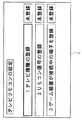
次に、図12〜図16を参照して、ユーザの操作に応じてテレビ2に表示される画面例について説明する。なお、図12は、コントローラ7を用いた操作に応じてテレビ2を制御可能とする設定を行う際に、テレビ2に表示される第1段階の画面例である。図13は、上記設定を行う際に、テレビ2に表示される第2段階の画面例である。図14は、上記設定を行う際に、テレビ2に表示される第3段階の画面例である。図15は、上記設定を行う際に、テレビ2に表示される第4段階の画面例である。図16は、上記設定を行う際に、テレビ2に表示される第5段階の画面例である。 Next, an example of a screen displayed on the
図12〜図16において、コントローラ7を用いた操作に応じてテレビ2を制御可能とする設定を行う際、ゲーム装置本体5から出力される映像音声信号による画像が、外部入力端子47を介してテレビ2に表示される状態で行われる。例えば、テレビ2の制御を可能とする設定を開始されると、テレビリモコンを設定する初期画面が表示される(図12)。当該初期画面では、上記設定において登録される登録状況(「1.テレビ機種の登録」、「2.リモコン信号の登録」、「3.ゲーム装置が接続中の端子を登録」)が表示される。ここで、ユーザは、コントローラ7で指し示す位置をテレビ2に表示された所望の画像位置に合わせて、コントローラ7の所定ボタンを押下することによって、コントローラ7で指し示された位置に表示されている選択肢を選択する操作が可能となる。そして、未登録となっている「1.テレビ機種の登録」を、ユーザがコントローラ7を用いて選択したとする。 In FIG. 12 to FIG. 16, when performing setting so that the
図12に示す画面においてユーザが「1.テレビ機種の登録」を選択すると、テレビメーカーの選択を促す画面が表示される(図13)。例えば、テレビメーカーの選択を促す画面では、テレビメーカーの一覧(「A社」、「B社」、「C社」…)が表示され、当該一覧から現在使用しているテレビ2のメーカーを選択するように促される。そして、ユーザは、テレビ2に表示されている上記一覧から、当該テレビ2のメーカーを選択する操作を行う。 When the user selects “1. Registration of TV model” on the screen shown in FIG. 12, a screen prompting the selection of the TV manufacturer is displayed (FIG. 13). For example, on the screen prompting the selection of the TV manufacturer, a list of TV manufacturers (“Company A”, “Company B”, “Company C”,...) Is displayed, and the manufacturer of the
図13に示す画面においてユーザがテレビ2のメーカーを選択すると、放送波の選択を促す画面が表示される(図14)。例えば、放送波の選択を促す画面では、地上デジタル放送やBSデジタル放送の対応状況を示す選択肢(「対応」、「非対応」)がそれぞれ表示され、当該対応状況からテレビ2の対応状況を選択するように促される。そして、ユーザは、テレビ2が受信可能な放送波の状況を選択する操作を行う。 When the user selects the manufacturer of the
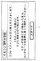
図14に示す画面においてテレビ2が受信可能な放送波の状況をユーザが選択すると、リモコン信号の登録を開始する旨を示す画面が表示される(図15)。例えば、リモコン信号の登録を開始する旨を示す画面では、以後切換テストが行われることが報知され、テレビ2の画面がテレビ放送に切り換わった後は、コントローラ7の音声に従って操作することが求められる。そして、ユーザは、テレビ2で表示された内容を確認した後、切換テストを開始する「スタート」を選択する操作を行う。 When the user selects a broadcast wave condition that can be received by the
図15に示す画面においてユーザが「スタート」を選択すると、今後の切換テストの概略内容やユーザに求められる事項を示す画面が表示される(図16)。例えば、テスト概略内容や要求事項を示す画面では、切換テストにおいて信号が発光された後にコントローラ7から音声がでることが報知され、その質問に返答するためにコントローラ7の操作ボタンを操作することが求められる。そして、ユーザは、テレビ2で表示された内容を確認した後、「OK」を選択する操作を行う。このような一連の表示および操作を経て、コントローラ7を用いた操作に応じてテレビ2を制御可能とする設定が行われる。 When the user selects “Start” on the screen shown in FIG. 15, a screen showing the outline of the future switching test and the items required by the user is displayed (FIG. 16). For example, on the screen showing the test outline contents and requirements, it is informed that a sound is emitted from the
次に、ゲームシステム1において行われる処理の詳細を説明する。まず、図17〜図19を参照して、処理において用いられる主なデータについて説明する。なお、図17は、ゲーム装置本体5の外部メインメモリ12および/または内部メインメモリ35(以下、2つのメインメモリを総称して、単にメインメモリと記載する)に記憶される主なデータの一例を示す図である。図18は、図17に示す信号テーブルデータDb1の詳細な内容の一例を示す図である。図19は、図17に示す音声メッセージデータDb2の詳細な内容の一例を示す図である。 Next, details of processing performed in the
図17に示すように、メインメモリには、操作情報Daおよび処理用情報Db等が記憶される。なお、メインメモリには、図17に示す情報に含まれるデータの他、情報処理や表示制御処理に必要なデータが適宜記憶される。 As shown in FIG. 17, the main memory stores operation information Da, processing information Db, and the like. The main memory appropriately stores data necessary for information processing and display control processing in addition to the data included in the information shown in FIG.
操作情報Daは、コントローラ7から送信データとして送信されてくる一連の操作情報(キーデータ、加速度データ、および処理結果データ)が格納され、最新の操作情報に更新される。操作情報Daには、上述の処理結果データの位置情報に相当する第1座標データDa1および第2座標データDa2が含まれる。第1座標データDa1は、撮像素子743が撮像した撮像画像に対して、2つのマーカ8Lおよび8Rのうちの一方の画像の位置(撮像画像内における位置)を示すデータである。第2座標データDa2は、他方のマーカの画像の位置(撮像画像内における位置)を示すデータである。例えば、撮像画像におけるマーカの画像の位置は、撮像画像におけるxy座標系によって表される。 The operation information Da stores a series of operation information (key data, acceleration data, and processing result data) transmitted from the
また、操作情報Daには、撮像画像から得られる処理結果データの一例の座標データ(第1座標データDa1および第2座標データDa2)の他、操作部72から得られるキーデータDa3等が含まれる。なお、ゲーム装置本体5に備える無線コントローラモジュール19は、コントローラ7から所定間隔例えば5msごとに送信される一連の操作情報を受信し、無線コントローラモジュール19に備える図示しないバッファに蓄えられる。その後、上記バッファに蓄えられた最新の操作情報がゲーム処理間隔である1フレーム毎(例えば1/60秒毎)に読み出されて、メインメモリの操作情報Daが更新される。 The operation information Da includes key data Da3 obtained from the
処理用情報Dbは、コントローラ7を用いた操作に応じてテレビ2を制御可能とする設定をするための情報やテレビ2に番組表を表示するための情報が格納される。処理用情報Dbは、信号テーブルデータDb1、音声メッセージデータDb2、テレビ機種登録データDb3、外部入力番号登録データDb4、設定完了フラグデータDb5、番組表データDb6、および画像データDb7等を含む。 In the processing information Db, information for setting the control of the
信号テーブルデータDb1は、予めテレビ機種毎に設定されている放送チャンネル信号および外部入力切換信号の信号パターンを示すデータが格納され、詳細は後述する。音声メッセージデータDb2は、コントローラ7から出力する音声メッセージを示すデータが格納され、詳細は後述する。テレビ機種登録データDb3は、ユーザの操作によって登録されたテレビ機種を示すデータが格納される。外部入力番号登録データDb4は、ゲーム装置本体5が接続されているテレビ2の外部入力番号を示すデータが格納される。設定完了フラグデータDb5は、コントローラ7を用いた操作に応じてテレビ2を制御可能とする設定が完了したか否かを示す設定完了フラグのデータが格納される。番組表データDb6は、テレビ2に番組表を表示するための各種データが格納される。画像データDb7は、設定処理の際にテレビ2に表示される画像や番組表をテレビ2に表示するための各種画像を示すデータが格納される。 The signal table data Db1 stores data indicating a signal pattern of a broadcast channel signal and an external input switching signal set in advance for each television model, and details will be described later. The voice message data Db2 stores data indicating a voice message output from the
図18において、信号テーブルデータDb1は、テレビ2に対する命令と、当該命令をテレビ2に実行させるために送信すべき赤外線信号の信号パターンとの対応情報を示す。信号テーブルデータDb1には、命令と信号パターンとの対応情報がテレビ機種毎に含まれる。なお、信号テーブルデータDb1には、同じテレビメーカーの機種(例えばA社製テレビ)であっても対応放送波(例えば地上波デジタル放送の対応/非対応、BSデジタル放送の対応/非対応)毎に異なる対応情報が含まれる。 In FIG. 18, signal table data Db1 indicates correspondence information between a command for the
例えば、A社製テレビにおける地上波デジタル放送およびBSデジタル放送共に非対応の機種においては、テレビ2で放送チャンネル1を視聴する命令と信号パターンaとが対応付けられている。そして、当該機種においては、テレビ2で視聴する放送チャンネル毎の命令に対して、それぞれ別の信号パターンが対応付けられている。また、当該機種においては、外部入力1を介して入力した映像音声信号をテレビ2で視聴する命令と信号パターンAとが対応付けられている。そして、当該機種においては、映像音声信号をテレビ2で視聴するために用いられる外部入力番号毎の命令に対して、それぞれ別の信号パターンが対応付けられている。 For example, in a model that does not support both terrestrial digital broadcasting and BS digital broadcasting on a television manufactured by Company A, a command for
さらに、A社製テレビにおける地上波デジタル放送非対応およびBSデジタル放送対応の機種においては、テレビ2で放送チャンネル1を視聴する命令と信号パターンfとが対応付けられており、他の放送チャンネルには別の信号パターンが対応付けられている。また、当該機種においては、外部入力1を介して入力した映像音声信号をテレビ2で視聴する命令と信号パターンFとが対応付けられており、他の外部入力番号には別の信号パターンが対応付けられている。このようなテレビ2に対する命令と、当該命令をテレビ2に実行させるために送信すべき赤外線信号の信号パターンとの対応情報は、他のメーカーについても同様にテレビ機種毎に用意されている。 Further, in a model that is incompatible with terrestrial digital broadcasting and BS digital broadcasting in a television manufactured by Company A, a command for viewing the
なお、信号テーブルデータDb1は、予め用意されており、例えばフラッシュメモリ17に予め記憶されている。また、ゲーム装置本体5は、新たなテレビ機種についての対応情報をネットワーク等から取得することによって、信号テーブルデータDb1の内容を更新してもよい。これによって、新たなテレビ機種が登場した場合でも、当該新たなテレビ機種に関する対応情報を容易に取得することができる。 The signal table data Db1 is prepared in advance and is stored in advance in the
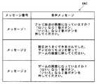
図19において、音声メッセージデータDb2は、コントローラ7のスピーカ706から音声出力する音声メッセージデータを示す。具体的には、音声メッセージデータDb2は、スピーカ706から音声出力するメッセージ番号と、音声メッセージを示すデータとの対応情報が示されている。 In FIG. 19, voice message data Db <b> 2 indicates voice message data output from the
例えば、メッセージ1に対して、「テレビ放送の画面になっていますか?「はい」なら1番ボタン、「いいえ」なら2番ボタンを押してください。」と音声出力するための音声メッセージデータが対応付けられている。また、メッセージ2に対して、「設定がうまくできませんでした。テレビのリモコンを使ってゲームの画面に戻してください。」と音声出力するための音声メッセージデータが対応付けられている。さらに、メッセージ3に対して、「ゲームの画面になっていますか?「はい」なら1番ボタン、「いいえ」なら2番ボタンを押してください。」と音声出力するための音声メッセージデータが対応付けられている。 For example, in response to
なお、音声メッセージデータDb2も、予め用意されており、例えばフラッシュメモリ17に予め記憶されている。また、ゲーム装置本体5は、新たな音声メッセージデータをネットワーク等から取得することによって、音声メッセージデータDb2の内容を更新してもよい。これによって、新たな音声メッセージをコントローラ7から出力したい場合でも、当該新たな音声メッセージを音声出力するためのデータを容易に取得することができる。 The voice message data Db2 is also prepared in advance, and is stored in advance in the
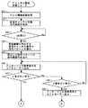
次に、図20〜図23を参照して、ゲーム装置本体5において行われる表示制御処理の詳細を説明する。なお、図20は、ゲーム装置本体5において実行される表示制御処理の流れを示すフローチャートである。図21は、図20のステップ51におけるチャンネル設定処理の詳細な動作を示す前半のサブルーチンである。図22は、図20のステップ51におけるチャンネル設定処理の詳細な動作を示す後半のサブルーチンである。図23は、テレビ2に表示される番組表の表示例を示す図である。なお、図20〜図22に示すフローチャートにおいては、表示制御処理のうち、主にコントローラ7を用いた操作に応じてテレビ2を制御可能とする設定処理と、番組表を用いてゲーム画面とテレビ放送画面とを切り換える処理について説明し、本願発明と直接関連しない他の処理については詳細な説明を省略する。また、図20〜図22では、CPU10が実行する各ステップを「S」と略称する。 Next, with reference to FIGS. 20 to 23, details of the display control processing performed in the
ゲーム装置本体5の電源ボタン24がオンされると、ゲーム装置本体5のCPU10は、ROM/RTC13に記憶されている起動用のプログラムを実行し、これによってメインメモリ等の各ユニットが初期化される。そして、光ディスク4や他の記録媒体に記憶された表示制御プログラムがメインメモリに読み込まれ、CPU10によって当該表示制御プログラムの実行が可能となる状態となる。図20に示すフローチャートは、以上の処理が完了した後に行われる表示制御処理を示すフローチャートである。 When the
図20において、CPU10は、チャンネル設定処理を行って(ステップ51)、次のステップ52に処理を進める。以下、図21を参照して、ステップ51で行うチャンネル設定処理について説明する。 In FIG. 20, the
図21において、CPU10は、テレビ機種登録処理を行って(ステップ81)、次のステップに処理を進める。例えば、CPU10は、ユーザ操作に応じて、メーカー名および対応放送波をテレビ2の機種として登録し、テレビ機種登録データDb3を更新する。具体的には、上記ステップ81において、CPU10は、テレビ2にテレビメーカーの一覧を表示して(図13参照)、当該一覧から現在使用しているテレビ2のメーカーを選択するように促す。また、CPU10は、テレビ2における地上デジタル放送やBSデジタル放送の対応状況を示す選択肢をそれぞれ表示して(図14参照)、当該選択肢から対応状況を選択するように促す。そして、CPU10は、ユーザがコントローラ7を操作して選択した事項に基づいて、テレビ機種登録データDb3を更新する。 In FIG. 21, the
なお、上記ステップ81において用いるユーザ操作は、コントローラ7から受信した操作情報を取得して行う。具体的には、CPU10は、取得した最新の操作情報を用いて操作情報Daを更新する。ここで、ステップ53で取得される操作情報には、マーカ8Lおよび8Rの撮像画像内における位置を示す処理結果データの他、コントローラ7の操作部72がどのように操作されたか示すキーデータが含まれている。ここでは、通信部75は、所定の時間間隔(例えば5ms間隔)で操作情報をゲーム装置本体5へ送信する。そして、CPU10は、送信された最新の操作情報を1フレーム毎に利用して、第1座標データDa1、第2座標データDa2、およびキーデータDa3を更新する。そして、CPU10は、操作情報Daの第1座標データDa1、第2座標データDa2、およびキーデータDa3を参照して、ユーザの操作内容(どの選択肢を選択したか)を決定する。 The user operation used in
次に、CPU10は、放送チャンネル切換指示画面を表示し(ステップ82)、ユーザからのOK指示を待つ(ステップ83)。例えば、上記ステップ82において、CPU10は、リモコン信号の登録を開始する旨を示す画面(図15)や、今後の切換テストの概略内容やユーザに求められる事項を示す画面(図16)を表示する。そして、CPU10は、コントローラ7からOKを指示する操作情報を取得したとき、次のステップ84に処理を進める。なお、上記ステップ83の処理においても、コントローラ7から受信した操作情報を用いて操作情報Daを更新し、当該更新後の操作情報Daを用いてOK指示の有無が判定される。 Next, the
ステップ84において、CPU10は、信号テーブルデータDb1を参照して、登録されたテレビ機種に対応する放送チャンネル信号の信号パターンの何れか1つを選出する。例えば、CPU10は、登録されたテレビ機種が、A社製で地上波デジタル放送およびBSデジタル放送共に非対応の機種である場合、当該機種の放送チャンネル1に対応する信号パターンaを選出する。そして、CPU10は、上記ステップ84で選出された信号パターンの赤外線信号を、LEDモジュール8に含まれる各赤外LED8Laおよび8Raに出力させ(ステップ85)、処理を次のステップに進める。このステップ85によって、LEDモジュール8の各赤外LED8Laおよび8Raは、信号パターンに応じて点灯および消灯を繰り返す。そして、テレビ2でテレビ放送(具体的には、ステップ84で選出された放送チャンネル信号の放送チャンネル)を視聴するためのリモコン信号が、LEDモジュール8から出力されることになる。一般的には、PPM(Pulse Position Modulation)信号(パルス位相変調信号)がリモコン信号として、LEDモジュール8から出力される。したがって、テレビ2が上記リモコン信号に正しく反応して動作制御されれば、ゲーム装置本体5から出力されている映像音声信号による画面(例えば、図16に示すような設定画面)からテレビ放送画面に切り換わることが予想される。 In step 84, the
次に、CPU10は、音声メッセージデータDb2を参照して、メッセージ1に対応する音声メッセージデータを示す音声信号をコントローラ7へ出力し(ステップ86)、次のステップに処理を進める。具体的には、CPU10は、無線コントローラモジュール19(図2参照)を介して、上記音声信号をゲーム装置本体5からコントローラ7へ送信する。そして、コントローラ7は、受信した上記音声信号が示す音声メッセージデータに応じて、スピーカ706から音声を出力する。したがって、コントローラ7を操作するユーザは、当該コントローラ7のスピーカ706からメッセージ1に対応する音声メッセージ(図19参照)を聞くことができる。 Next, the
次に、CPU10は、コントローラ7の1番ボタン(操作ボタン72b)が押下されたか否か(ステップ87)、およびコントローラ7の2番ボタン(操作ボタン72c)が押下されたか否か(ステップ88)を判断する。そして、CPU10は、1番ボタンが押下された場合、次のステップ91(図22)に処理を進める。一方、CPU10は、2番ボタンが押下された場合、次のステップ89に処理を進める。また、CPU10は、1番ボタンおよび2番ボタンの何れも押下されていない場合、上記ステップ86に戻って音声メッセージの出力を継続する。なお、上記ステップ86〜ステップ88の処理においては、コントローラ7のスピーカ706からメッセージ1、すなわち「テレビ放送の画面になっていますか?「はい」なら1番ボタン、「いいえ」なら2番ボタンを押してください。」という音声が出力されているため、ユーザは当該音声にしたがってテレビ2の画面を確認して1番ボタンまたは2番ボタンを押下することが促される。また、上記ステップ87およびステップ88の処理においても、コントローラ7から受信した操作情報を用いて操作情報Daを更新し、当該更新後の操作情報Daを用いてユーザの操作が判断される。 Next, the
ステップ89において、CPU10は、音声メッセージデータDb2を参照して、メッセージ2に対応する音声メッセージデータを示す音声信号をコントローラ7へ出力し、当該サブルーチンによる処理を終了する。具体的には、CPU10は、上記ステップ86と同様に、上記音声信号に応じた音声をスピーカ706から出力させる。したがって、コントローラ7を操作するユーザは、当該コントローラ7のスピーカからメッセージ2に対応する音声メッセージ(図19参照)を聞くことができる。具体的には、上記ステップ89の処理は、ユーザが2番ボタンを押下した場合、すなわち、テレビ2にテレビ放送画面が表示されていない場合である。つまり、テレビ2が上記ステップ85で出力した赤外線信号に正しく反応していない、またはテレビ2がテレビ放送を正常に受信できない場合等が考えられる。したがって、上記ステップ89においては、コントローラ7のスピーカ706からメッセージ2、すなわち「設定がうまくできませんでした。テレビのリモコンを使ってゲームの画面に戻してください。」という音声が出力することによって、コントローラ7を用いた操作に応じてテレビ2を制御可能とする設定処理ができなかったことをユーザに通知する。また、ユーザは、上記音声にしたがってテレビ2のリモコンを用いてテレビ2にゲーム画面を表示するように促される。 In
図22において、CPU10は、処理に用いる一時変数nを1に設定し(ステップ91)、次のステップに処理を進める。 In FIG. 22, the
次に、CPU10は、信号テーブルデータDb1を参照して、登録されたテレビ機種に対応する外部入力nの外部入力切換信号の信号パターンを選出する(ステップ92)。例えば、CPU10は、登録されたテレビ機種が、A社製で地上波デジタル放送およびBSデジタル放送共に非対応の機種であり、現在の一時変数n=1の場合、当該機種の外部入力1に対応する信号パターンAを選出する。また、CPU10は、現在の一時変数n=2の場合、当該機種の外部入力2に対応する信号パターンBを選出する。そして、CPU10は、上記ステップ92で選出された信号パターンの赤外線信号を、LEDモジュール8に含まれる各赤外LED8Laおよび8Raに出力させ(ステップ93)、処理を次のステップに進める。このステップ93によって、外部入力nの外部入力端子47を介した映像音声信号による画像および音声をテレビ2で視聴するためのリモコン信号が、LEDモジュール8から出力されることになる。したがって、テレビ2が上記リモコン信号に正しく反応して動作制御されれば、外部入力nを介した映像音声信号による画面にテレビ2が切り換わることが予想される。 Next, the
次に、CPU10は、音声メッセージデータDb2を参照して、メッセージ3に対応する音声メッセージデータを示す音声信号をコントローラ7へ出力し(ステップ94)、次のステップに処理を進める。具体的には、CPU10は、上記ステップ86と同様に、上記音声信号に応じた音声をスピーカ706から出力させる。したがって、コントローラ7を操作するユーザは、当該コントローラ7のスピーカからメッセージ3に対応する音声メッセージ(図19参照)を聞くことができる。 Next, the
次に、CPU10は、コントローラ7の1番ボタン(操作ボタン72b)が押下されたか否か(ステップ95)、およびコントローラ7の2番ボタン(操作ボタン72c)が押下されたか否か(ステップ98)を判断する。そして、CPU10は、1番ボタンが押下された場合、次のステップ96に処理を進める。一方、CPU10は、2番ボタンが押下された場合、次のステップ99に処理を進める。また、CPU10は、1番ボタンおよび2番ボタンの何れも押下されていない場合、上記ステップ94に戻って音声メッセージの出力を継続する。なお、上記ステップ94、ステップ95、およびステップ98の処理においては、コントローラ7のスピーカ706からメッセージ3、すなわち「ゲームの画面になっていますか?「はい」なら1番ボタン、「いいえ」なら2番ボタンを押してください。」という音声が出力されているため、ユーザは当該音声にしたがってテレビ2の画面を確認して1番ボタンまたは2番ボタンを押下することが促される。また、上記ステップ95およびステップ98の処理においても、コントローラ7から受信した操作情報を用いて操作情報Daを更新し、当該更新後の操作情報Daを用いてユーザの操作が判断される。 Next, the
ステップ96において、CPU10は、現在の一時変数nに基づいて、外部入力nを適合する外部入力番号として登録し、外部入力番号登録データDb4を更新する。そして、CPU10は、設定完了フラグをONにして設定完了フラグデータDb5を更新して(ステップ97)、当該サブルーチンによる処理を終了する。ここで、上記ステップ96の処理は、ユーザが1番ボタンを押下した場合、すなわち、テレビ2にゲーム画面が表示されている場合である。つまり、テレビ2の外部入力nの外部入力端子47にゲーム装置本体5が接続され、当該外部入力端子47を介してゲーム画面がテレビ2に正常に表示されていることが推定できる。したがって、上記ステップ96においては、ゲーム装置本体5がテレビ2の外部入力nに接続されているとして、当該外部入力nを適合する外部入力番号として登録する。 In step 96, the
一方、ステップ99において、CPU10は、現在の一時変数nが登録されているテレビ機種の最大値nmaxであるか否かを判断する。そして、CPU10は、一時変数nが最大値nmaxに到達していない場合、一時変数nに1を加算し(ステップ101)、上記ステップ92に戻って処理を繰り返す。一方、CPU10は、n=nmaxの場合、次のステップ100に処理を進める。ここで、最大値nmaxは、テレビ機種毎に設定されている外部入力番号の最大値である。例えば、図18に示すように、A社製で地上波デジタル放送およびBSデジタル放送共に非対応の機種では、外部入力端子が3つ設定されており最大値nmax=3である。また、A社製で地上波デジタル放送が非対応およびBSデジタル放送が対応の機種では、外部入力端子が4つ設定されており最大値nmax=4である。さらに、A社製で地上波デジタル放送およびBSデジタル放送共に対応の機種では、外部入力端子が5つ設定されており最大値nmax=5である。 On the other hand, in
ステップ100において、CPU10は、音声メッセージデータDb2を参照して、メッセージ2に対応する音声メッセージデータを示す音声信号をコントローラ7へ出力し、当該サブルーチンによる処理を終了する。具体的には、CPU10は、上記ステップ86と同様に、上記音声信号に応じた音声をスピーカ706から出力させる。したがって、コントローラ7を操作するユーザは、当該コントローラ7のスピーカからメッセージ2に対応する音声メッセージ(図19参照)を聞くことができる。具体的には、上記ステップ100の処理は、ユーザが2番ボタンの押下を繰り返して一時変数nが最大値nmaxに到達した場合、すなわち、テレビ2の何れの外部入力端子47を選択してもゲーム画面が表示されない場合である。つまり、テレビ2が上記ステップ93で出力した赤外線信号に正しく反応していない、またはテレビ2とゲーム装置本体5との接続不良等が考えられる。したがって、上記ステップ100においては、コントローラ7のスピーカ706からメッセージ2、すなわち「設定がうまくできませんでした。テレビのリモコンを使ってゲームの画面に戻してください。」という音声が出力することによって、コントローラ7を用いた操作に応じてテレビ2を制御可能とする設定処理ができなかったことをユーザに通知する。また、ユーザは、上記音声にしたがってテレビ2のリモコンを用いてテレビ2にゲーム画面を表示するように促される。 In step 100, the
図20に戻り、ステップ51のチャンネル設定処理の後、CPU10は、テレビ2に番組表を表示し(ステップ52)、次のステップに処理を進める。上記ステップ52の処理においては、CPU10は、無線通信モジュール18およびアンテナ22を介してネットワークに接続される各種サーバと通信することによって得られる電子番組表データを用いて、番組表データDb6に記述される各情報を適宜最新の情報に更新し、番組表の設定を行う。そして、CPU10は、番組表データDb6に基づいて、テレビ2に番組表を表示する。 Returning to FIG. 20, after the channel setting process in step 51, the
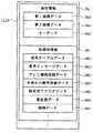
例えば、図23に示すように、テレビ2には横軸を時間軸、縦軸を放送局軸としたマトリックス状の番組表が表示される。具体的には、各テレビ局が放送する時間帯に応じた番組セルがそれぞれ設定され、各番組セル内に番組名が文字で記述される。ここで、ユーザは、コントローラ7の所定ボタンを押下したり、コントローラ7で指し示す位置を変更したりすることによって、番組名の文字サイズを変更したり、番組表をスクロールしたり、時間軸の長さを伸縮したりすることができる。また、ユーザは、コントローラ7で所望の番組セルやテレビチャンネルを指し示しながら所定ボタン(例えば、操作ボタン72d(Aボタン))を押下することによって、当該テレビチャンネルのテレビ放送をテレビ2で視聴することができる。 For example, as shown in FIG. 23, the
次に、CPU10は、番組表に表示された何れかのチャンネルを視聴する選択がされたか否かを判断する(ステップ53)。具体的には、CPU10は、コントローラ7から受信した操作情報を用いて操作情報Daを更新し、当該更新後の操作情報Daを用いてチャンネルを視聴する選択をユーザが行ったか否かを判断する。例えば、CPU10は、第1座標データDa1および第2座標データDa2を用いて、コントローラ7が指し示している位置を算出し、当該指し示し位置に対応する番組表のテレビチャンネルを選出する。そして、キーデータDa3を用いてユーザが視聴を選択する所定ボタンを押下していると判定されたとき、CPU10は、コントローラ7で指し示されているテレビチャンネルをテレビ2で視聴する選択がされたと判断する。そして、CPU10は、チャンネルを視聴する選択がされた場合、次のステップ54に処理を進める。一方、CPU10は、チャンネルを視聴する選択がされていない場合、操作情報Daに基づいてその他の処理を行い(ステップ60)、次のステップ59に処理を進める。 Next, the
ステップ54において、CPU10は、設定完了フラグデータDb5を参照して、設定完了フラグがONであるか否かを判断する。そして、CPU10は、設定完了フラグがONの場合、次のステップ55に処理を進める。一方、CPU10は、設定完了フラグがOFFの場合、次のステップ59に処理を進める。 In
ステップ55において、CPU10は、信号テーブルデータDb1を参照して、登録されたテレビ機種に対応する放送チャンネル信号の信号パターンのうち、上記ステップ53で視聴選択されたチャンネルの信号パターンを選出する。例えば、CPU10は、登録されたテレビ機種が、A社製で地上波デジタル放送およびBSデジタル放送共に非対応の機種であり、上記ステップ53で視聴選択されたチャンネルが放送チャンネル2の場合、信号パターンbを選出する(図18参照)。そして、CPU10は、上記ステップ55で選出された信号パターンの赤外線信号を、LEDモジュール8に含まれる各赤外LED8Laおよび8Raに出力させ(ステップ56)、処理を次のステップに進める。このステップ56によって、ユーザが視聴選択したチャンネルのテレビ放送をテレビ2で視聴するためのリモコン信号が、LEDモジュール8から出力されることになる。したがって、ユーザは、コントローラ7を操作することによって、ゲーム装置本体5から出力されている映像音声信号による画面(例えば、図23に示すような番組表画面)から視聴選択したチャンネルのテレビ放送画面に切り換えることができる。 In step 55, the
次に、CPU10は、番組表の表示に戻る操作が行われるのを待つ(ステップ57)。具体的には、CPU10は、コントローラ7から受信した操作情報を用いて操作情報Daを更新し、当該更新後の操作情報Daを用いて番組表の表示に戻る操作をユーザが行ったか否かを判断する。例えば、キーデータDa3を参照して、ユーザがゲーム画面の表示に戻ることを示す所定ボタン(例えば、操作ボタン72f(ホームボタン))を押下していると判定されたとき、CPU10は、番組表の表示に戻る操作が行われたと判断する。そして、CPU10は、番組表の表示に戻る操作がチャンネルを視聴する選択がされた場合、次のステップ58に処理を進める。 Next, the
ステップ58において、CPU10は、ゲーム装置本体5に適合する外部入力番号の信号パターンの赤外線信号を出力し、次のステップ59に処理を進める。具体的には、CPU10は、外部入力番号登録データDb4を参照して、適合する外部入力番号(ゲーム装置本体5がテレビ2接続されている外部入力端子47の外部入力番号)を取得する。そして、CPU10は、信号テーブルデータDb1を参照して、登録されたテレビ機種に対応する適合する外部入力番号の外部入力切換信号の信号パターンを選出する。そして、CPU10は、選出された信号パターンの赤外線信号を、LEDモジュール8に含まれる各赤外LED8Laおよび8Raに出力させる。このステップ58によって、適合する外部入力番号の外部入力端子47を介した映像音声信号による画像および音声をテレビ2で視聴するためのリモコン信号が、LEDモジュール8から出力されることになる。したがって、当該外部入力端子47に接続されたゲーム装置本体5から出力されている映像音声信号による画像および音声が、テレビ2で視聴可能となる。 In
ステップ59において、CPU10は、処理を終了するか否かを判断する。処理を終了する条件としては、例えば、番組表が表示終了となる条件が満たされたことや、ユーザが処理を終了する操作を行ったこと等がある。CPU10は、処理を終了しない場合に上記ステップ52に戻って処理を繰り返し、処理を終了する場合に当該フローチャートによる処理を終了する。 In step 59, the
上記ステップ53〜ステップ58の処理から明らかなように、設定完了フラグがOFFの場合は、ユーザがテレビチャンネルを視聴する操作を行ったとしてもテレビ放送画面に切り換わらない。これは、設定完了フラグが上記ステップ97、すなわちコントローラ7を用いた操作に応じてテレビ2を制御可能とする設定処理が完了したときにONされるデータであり、OFFのときは当該処理が完了していないことを示している。つまり、コントローラ7を用いた操作に応じてテレビ2を制御可能とする設定処理が完了していない場合は、ユーザがチャンネルを視聴する操作を行ったとしてもテレビ放送画面に切り換えることができない。 As is apparent from the processing in
なお、上述したステップ56の処理の後、コントローラ7のスピーカ706から何らかの音声情報を出力してもかまわない。例えば、メッセージ1、すなわち「テレビ放送の画面になっていますか?「はい」なら1番ボタン、「いいえ」なら2番ボタンを押してください。」というようなテレビ放送画面が表示されているか確認するような情報を、コントローラ7のスピーカ706から出力してもかまわない。ここで、上記ステップ51のチャンネル設定処理を経た後に上記ステップ56の処理が行われている場合は、テレビ2にテレビ放送画面が表示されない可能性は低い。しかしながら、上記ステップ56において何らかの原因でテレビ2にテレビ放送画面が表示されない場合(例えば、チャンネル設定処理の後、ユーザがゲーム装置本体5を接続するテレビ2を変更した場合や、機器の不良等)、ユーザにはテレビ2やゲーム装置本体5から何の情報も得られないことになる。このような状況においても、コントローラ7のスピーカ706から情報を出力することによって、ユーザは適切な操作が可能となる。 Note that some audio information may be output from the
また、上述したステップ58の処理の後でも、コントローラ7のスピーカ706から何らかの音声情報を出力してもかまわない。例えば、メッセージ3、すなわち「ゲームの画面になっていますか?「はい」なら1番ボタン、「いいえ」なら2番ボタンを押してください。」というようなゲーム画面(番組表画面)が表示されているか確認するような情報を、コントローラ7のスピーカ706から出力してもかまわない。これによって、上記ステップ58において何らかの原因でテレビ2にゲーム画面が表示されない場合においても、コントローラ7のスピーカ706から情報を出力することによって、ユーザは適切な操作が可能となる。また、このような音声情報を出力することによって、テレビ放送画面に切り換わらない場合やゲーム画面に切り換わらない場合の対応が可能となる。したがって、上述したステップ51のチャンネル設定処理を行わずに、当該ステップ56およびステップ58の処理およびユーザ操作をテレビ機種毎に繰り返すことによって、上述したチャンネル設定を行ってもかまわない。 Further, some audio information may be output from the
このように、本実施形態に係る表示制御プログラムを実行するゲーム装置本体5では、2つの映像音声信号(例えば、ゲーム装置本体5からの映像音声信号とテレビ2のチューナ45が受信した放送信号による映像音声信号)による映像音声の何れかを選択的にテレビ2に表示出力する場合に、選択された映像音声信号に応じた音声情報をテレビ2とは別の機器から報知することができる。したがって、例えば、放送信号によるテレビ放送画像がテレビ2で表示されている場合やゲーム装置本体5によって生成された画像が適切にテレビ2に表示されていない場合であっても、ゲーム装置本体5からの情報をユーザに報知することができる。 As described above, in the
なお、上述した説明では、ゲーム装置本体5からテレビ2に、設定画像(図12〜図16)や番組表画像(図23)を示す映像音声信号が出力される例を示したが、他の画像を示す映像音声信号がゲーム装置本体5からテレビ2へ出力されてもかまわない。例えば、ゲーム装置本体5からテレビ2に、ゲーム画像を示す映像音声信号が出力されてもかまわない。この場合、ゲーム装置本体5からテレビ2に出力するゲーム画像中に、例えば放送チャンネルアイコンを含めておく。そして、ユーザがゲーム画像中の放送チャンネルアイコンを選択操作することに応じて、当該選択された放送チャンネルを視聴可能とする放送チャンネル信号を示す赤外線信号をLEDモジュール8から出力するようにすればよい。 In the above description, an example in which a video / audio signal indicating a setting image (FIGS. 12 to 16) and a program guide image (FIG. 23) is output from the
また、上述した説明では、ゲーム装置本体5からの映像音声信号とテレビ2のチューナ45が受信した放送信号による映像音声信号とによる映像音声の何れかを選択的にテレビ2に表示出力する場合に、選択された映像音声信号に応じた音声情報をゲーム装置本体5で報知する例を示したが、他の機器からの映像音声信号でもかまわない。例えば、テレビ2の外部入力端子47に接続されたゲーム装置本体5と、他の外部入力端子47に接続された機器(例えば、ハードディスク・レコーダ等の映像音声録画/再生装置やパーソナルコンピュータ等)との間の表示切り換えに、本発明を適用してもかまわない。この場合、ゲーム装置本体5からの映像音声信号と他の機器からの映像音声信号とによる映像音声の何れかを選択的にテレビ2に表示出力する場合に、選択された映像音声信号に応じた音声情報がゲーム装置本体5から報知される。 Further, in the above description, when either the video / audio signal from the video / audio signal from the game apparatus
また、上述した説明では、選択された映像音声信号に応じた情報を、コントローラ7のスピーカ706から音声出力する例を用いたが、音声情報とは異なる画像情報でユーザに報知してもかまわない。例えば、コントローラ7に表示画面を設け、ゲーム装置本体5から送信されたメッセージ(例えば、上記メッセージ1〜3)を当該表示画面に表示する。これによって、ユーザはコントローラ7の表示画面に表示されたメッセージを見て、ゲーム装置本体5から情報を得ることができる。このように画像情報でユーザに情報を報知する場合、ゲーム装置本体5から情報が表示されていることをユーザに気づかせるために、さらにコントローラ7に振動を加えてもかまわない。上述したように、コントローラ7にはバイブレータ704が内蔵されているため、ゲーム装置本体5がメッセージの送信と同時にバイブレータ704を振動させる振動データもコントローラ7へ送信すれば、画像情報の表示に振動による通知を加えて、ユーザに報知することができる。 In the above description, the example in which information corresponding to the selected video / audio signal is output from the
また、選択された映像音声信号に応じた音声情報を、他の機器から出力してもかまわない。例えば、ゲーム装置本体5やLEDモジュール8にスピーカを設け、当該スピーカから上記音声情報を出力してもかまわない。 Further, audio information corresponding to the selected video / audio signal may be output from another device. For example, a speaker may be provided in the
また、上述した説明では、LEDモジュール8の各赤外LED8Laおよび8Raを、信号パターンに応じて点滅させることによって出力される赤外線信号を用いてテレビ2を制御する例を用いたが、他の機器から赤外線信号を出力してもかまわない。例えば、コントローラ7に赤外線送信部を設け、当該赤外線送信部から赤外線信号を出力してテレビ2を制御してもかまわない。この場合、コントローラ7の赤外線送信部は、基板700等に形成された配線によってマイコン751と接続され、ゲーム装置本体5から送信された信号パターンに応じて赤外線信号を出力する。つまり、CPU10は、信号パターンに応じた赤外線信号を出力する処理において、当該信号パターンを含むデータをコントローラ7へ送信し、当該データを受信したコントローラ7の赤外線送信部が当該信号パターンに応じた赤外線信号を出力する。 In the above description, the example in which the
また、上述した説明では、赤外線信号を用いてテレビ2の動作を制御する例を用いたが、他の無線通信方式を用いてテレビ2の動作を制御してもかまわない。例えば、無線LAN、ジグビー(ZigBee;登録商標)、ブルートゥース(登録商標)等の電磁波による無線通信方式を用いてテレビ2の動作が制御可能であれば、これらの無線通信方式を用いてテレビ2を制御してもかまわない。 In the above description, an example in which the operation of the
また、撮像素子743で撮像した画像データを解析してマーカ8Lおよび8Rからの赤外光の位置座標やそれらの重心座標等を取得し、それらを処理結果データとしてコントローラ7内で生成してゲーム装置本体5へ送信する態様を説明したが、他の処理段階のデータをコントローラ7からゲーム装置本体5へ送信してもかまわない。例えば、撮像素子743が撮像した画像データをコントローラ7からゲーム装置本体5へ送信し、CPU10において上記解析処理を行って処理結果データを取得してもかまわない。この場合、コントローラ7に設けられた画像処理回路744が不要となる。また、上記画像データの解析途中のデータをコントローラ7からゲーム装置本体5へ送信してもかまわない。例えば、画像データから得られる輝度、位置、および面積等を示すデータをコントローラ7からゲーム装置本体5へ送信し、CPU10において残りの解析処理を行って処理結果データを取得してもかまわない。 Further, the image data picked up by the
また、上述した説明では、2つのマーカ8Lおよび8Rからの赤外光を、コントローラ7の撮像情報演算部74の撮像対象としたが、他のものを撮像対象にしてもかまわない。例えば、1つまたは3つ以上のマーカをテレビ2の近傍に設置し、それらのマーカからの赤外光を撮像情報演算部74の撮像対象としてもかまわない。また、テレビ2の表示画面自体や他の発光体(室内灯等)を撮像情報演算部74の撮像対象としてもかまわない。撮像対象とテレビ2の表示画面との配置関係に基づいて、当該表示画面に対するコントローラ7の指し示し位置を演算すれば、様々な発光体を撮像情報演算部74の撮像対象として用いることができる。 In the above description, the infrared light from the two
また、上述した説明では、コントローラ7とゲーム装置本体5とが無線通信によって接続された態様を用いたが、コントローラ7とゲーム装置本体5とがケーブルを介して電気的に接続されてもかまわない。この場合、コントローラ7に接続されたケーブルをゲーム装置本体5の接続端子に接続する。 In the above description, the
また、上述したコントローラ7の形状や、それらに設けられている操作部72の形状、数、および設置位置等や、表示制御処理で用いる処理順序や操作ボタン等は、単なる一例に過ぎず他の形状、数、設置位置、処理順序、操作ボタンであっても、本発明を実現できることは言うまでもない。また、コントローラ7における撮像情報演算部74の位置(撮像情報演算部74の光入射口)は、ハウジング71の前面でなくてもよく、ハウジング71の外部から光を取り入れることができれば他の面に設けられてもかまわない。また、LEDモジュール8をテレビ2の画面の上側に配置した態様で説明したが、他の位置に配置してもかまわない。例えば、LEDモジュール8をテレビ2の画面の下側に配置してもかまわない。また、コントローラ7の撮像情報演算部74の撮像対象としてLEDモジュール8を用いない場合は、テレビ2の画面の左側または右側や、赤外線照射方向とテレビ2の正面とが対向するように、LEDモジュール8を配置してもかまわない。テレビ2の受光部42が赤外線信号を受光できる位置にLEDモジュール8が配置されていれば、どのような位置にLEDモジュール8が配置されてもかまわない。 In addition, the shape of the
また、上述した説明では、据置型のゲーム装置に本願発明を適用した例を説明したが、本発明は、テレビジョン受像器に接続されてリモコン等の入力装置によって操作される他の機器にも適用することができる。例えば、本発明は、一般的なパーソナルコンピュータ等の情報処理装置や、DVD(Digital Versatile Disc)レコーダ、DVDプレーヤ、ビデオレコーダ等の映像音声録画/再生装置等における表示制御にも適用することができる。 In the above description, an example in which the present invention is applied to a stationary game apparatus has been described. However, the present invention can be applied to other equipment connected to a television receiver and operated by an input device such as a remote controller. Can be applied. For example, the present invention can be applied to display control in an information processing apparatus such as a general personal computer, and a video / audio recording / reproducing apparatus such as a DVD (Digital Versatile Disc) recorder, DVD player, or video recorder. .
また、本発明の表示制御プログラムは、ゲーム装置本体5内部の不揮発性記憶装置に予め記録されるだけでなく、光ディスク4等の外部記憶媒体を通じてゲーム装置本体5に供給されてもよい。なお、表示制御プログラムを記憶する情報記憶媒体としては、CD−ROM、DVD、あるいはそれらに類する光学式ディスク状記憶媒体の他に、不揮発性半導体メモリでもよい。また、当該表示制御プログラムは、有線または無線の通信回線を通じてゲーム装置本体5に供給されてもよい。 Further, the display control program of the present invention may be supplied not only to the nonvolatile storage device inside the
以上、本発明を詳細に説明してきたが、上述の説明はあらゆる点において本発明の例示にすぎず、その範囲を限定しようとするものではない。本発明の範囲を逸脱することなく種々の改良や変形を行うことができることは言うまでもない。 Although the present invention has been described in detail above, the above description is merely illustrative of the present invention in all respects and is not intended to limit the scope thereof. It goes without saying that various improvements and modifications can be made without departing from the scope of the present invention.
本発明に係る表示制御プログラムおよび表示制御装置は、2つの映像音声信号による映像音声の何れかを選択的にテレビジョン受像器等の表示装置に表示出力する場合に、選択された映像音声信号に応じた情報を報知することができ、テレビジョン受像器に接続されるゲーム装置や映像音声録画/再生装置等の機器や当該機器で実行されるプログラムとして有用である。 The display control program and the display control device according to the present invention provide a selected video / audio signal when the video / audio of the two video / audio signals is selectively displayed on a display device such as a television receiver. The corresponding information can be notified, and it is useful as a program executed by a device such as a game device or a video / audio recording / reproducing device connected to the television receiver or the device.
1…ゲームシステム
2…テレビ
40…マイコン
41、706…スピーカ
42…受光部
43…表示部
44…操作部
45…チューナ
46…入力切換部
47…外部入力端子
3…ゲーム装置
4…光ディスク
5…ゲーム装置本体
10…CPU
11…システムLSI
12…外部メインメモリ
13…ROM/RTC
14…ディスクドライブ
15…AV−IC
16…AVコネクタ
17…フラッシュメモリ
18…無線通信モジュール
19…無線コントローラモジュール
20…拡張コネクタ
21…外部メモリカード用コネクタ
22、23…アンテナ
24…電源ボタン
25…リセットボタン
26…イジェクトボタン
27…LED制御部
31…入出力プロセッサ
32…GPU
33…DSP
34…VRAM
35…内部メインメモリ
7…コントローラ
71…ハウジング
72…操作部
73…コネクタ
74…撮像情報演算部
741…赤外線フィルタ
742…レンズ
743…撮像素子
744…画像処理回路
75…通信部
751…マイコン
752…メモリ
753…無線モジュール
754…アンテナ
700…基板
701…加速度センサ
702…LED
704…バイブレータ
707…サウンドIC
708…アンプ
8…LEDモジュール
8L、8R…マーカ
8LC、8RC…カバー
8La、8Ra…赤外LED
DESCRIPTION OF
11 ... System LSI
12 ... External main memory 13 ... ROM / RTC
14 ...
16 ...
33 ... DSP
34 ... VRAM
35 ... Internal
704 ...
708 ...
Claims (15)
Translated fromJapanese前記表示装置に第1画像を表示するための第1映像音声信号を生成して、前記表示装置へ出力する第1映像音声信号生成手段と、
前記第1映像音声信号に基づいた第1画像を前記表示装置に表示させる命令を示す第1信号パターンおよび前記表示制御装置とは別の機器から得られた第2映像音声信号に基づいた第2画像を前記表示装置に表示させる命令を示す第2信号パターンを記憶する信号パターン記憶手段と、
前記第1信号パターンおよび前記第2信号パターンの何れか一方を選択する選択手段と、
前記無線通信を用いて、前記選択手段が選択した信号パターンの無線信号を前記表示装置に出力する無線出力手段と、
前記無線出力手段によって出力された無線信号の信号パターンに応じて、当該信号パターンにしたがって決められる情報を前記表示装置とは別の装置から報知する報知手段とを備える、表示制御装置。A display control device connected to a display device that can be remotely operated using wireless communication,
First video / audio signal generating means for generating a first video / audio signal for displaying a first image on the display device and outputting the first video / audio signal to the display device;
A first signal pattern indicating a command to display a first image based on the first video / audio signal on the display device, and a second based on a second video / audio signal obtained from a device different from the display control device. Signal pattern storage means for storing a second signal pattern indicating an instruction to display an image on the display device;
Selecting means for selecting one of the first signal pattern and the second signal pattern;
Wireless output means for outputting a wireless signal of the signal pattern selected by the selection means to the display device using the wireless communication;
A display control apparatus comprising: a notification unit configured to notify information determined according to the signal pattern from a device different from the display device according to a signal pattern of the wireless signal output by the wireless output unit.
前記入力装置から前記ユーザ入力データを取得する入力データ取得手段とを、さらに備え、
前記報知手段は、前記入力装置に設けられ、
前記選択手段は、前記入力データ取得手段が取得したユーザ入力データに応じて、前記第1信号パターンおよび前記第2信号パターンの何れか一方を選択する、請求項1に記載の表示制御装置。An input device for receiving user input and outputting user input data;
Input data acquisition means for acquiring the user input data from the input device,
The notification means is provided in the input device,
The display control apparatus according to claim 1, wherein the selection unit selects one of the first signal pattern and the second signal pattern according to user input data acquired by the input data acquisition unit.
前記報知手段は、前記無線出力手段によって出力された無線信号の信号パターンに応じて、前記情報記憶手段に記憶されている複数の情報から選択し、選択された情報を報知する、請求項1または2に記載の表示制御装置。Information storage means for storing in advance a plurality of information determined according to the signal pattern,
The notification means selects from a plurality of information stored in the information storage means according to a signal pattern of a wireless signal output by the wireless output means, and notifies the selected information. The display control apparatus according to 2.
前記報知手段は、前記第2信号パターンの無線信号が出力された場合、前記第2映像音声信号に関する情報を報知する、請求項4に記載の表示制御装置。When the wireless signal of the first signal pattern is output, the notification means notifies information related to the first video / audio signal,
The display control apparatus according to claim 4, wherein when the wireless signal having the second signal pattern is output, the notification unit notifies information related to the second video / audio signal.
前記報知手段は、前記第2信号パターンの無線信号が出力された場合、前記表示装置に前記第2画像が表示されているか否かの確認を促す情報を報知する、請求項4に記載の表示制御装置。When the wireless signal of the first signal pattern is output, the notification means notifies information for prompting whether or not the first image is displayed on the display device,
5. The display according to claim 4, wherein when the wireless signal having the second signal pattern is output, the notifying unit notifies information prompting to confirm whether or not the second image is displayed on the display device. Control device.
前記報知手段は、前記第2信号パターンの無線信号が出力された場合、前記表示装置に前記第2画像が表示されているか否かを確認し、その確認結果を前記入力装置に入力するように促す情報を報知する、請求項2に記載の表示制御装置。The notification means confirms whether the first image is displayed on the display device when a wireless signal of the first signal pattern is output, and inputs the confirmation result to the input device. Inform the prompting information,
When the radio signal of the second signal pattern is output, the notification unit checks whether the second image is displayed on the display device, and inputs the check result to the input device. The display control apparatus of Claim 2 which alert | reports the information to prompt | urge.
外部から映像音声信号が入力される複数の外部入力端子と、
放送局からのテレビジョン信号を受信して前記第2映像音声信号を生成するチューナとを含み、
前記表示制御装置は、前記複数の外部入力端子の何れか1つと接続され、
前記第1信号パターンは、前記複数の外部入力端子に入力されたそれぞれの映像音声信号に基づいた第1画像を前記表示装置に表示させる命令を示し、前記外部入力端子毎に対応して異なる複数の信号パターンをそれぞれ有し、
前記選択手段は、前記第1信号パターンを選択する場合、前記複数の信号パターンから前記外部入力端子毎に順次異なる信号パターンを選択し、
前記報知手段は、前記第1信号パターンの無線信号が出力された場合、前記表示装置に前記第1画像が表示されているか否かを確認し、その確認結果を前記入力装置に入力するように促す情報を報知し、
前記表示制御装置は、前記入力データ取得手段が取得したユーザ入力データに基づいて、前記表示装置に接続されている当該表示制御装置の前記外部入力端子に対応する信号パターンを前記複数の信号パターンから特定する第1信号パターン特定手段を、さらに備える、請求項2に記載の表示制御装置。The display device
A plurality of external input terminals to which video and audio signals are input from the outside;
A tuner that receives a television signal from a broadcasting station and generates the second video and audio signal;
The display control device is connected to any one of the plurality of external input terminals,
The first signal pattern indicates a command for causing the display device to display a first image based on each video / audio signal input to the plurality of external input terminals, and a plurality of different ones corresponding to the external input terminals. Each having a signal pattern of
The selecting means, when selecting the first signal pattern, sequentially select different signal patterns for each of the external input terminals from the plurality of signal patterns,
The notification means confirms whether the first image is displayed on the display device when a wireless signal of the first signal pattern is output, and inputs the confirmation result to the input device. Inform the prompting information,
The display control device, based on the user input data acquired by the input data acquisition means, extracts a signal pattern corresponding to the external input terminal of the display control device connected to the display device from the plurality of signal patterns. The display control apparatus according to claim 2, further comprising first signal pattern specifying means for specifying.
外部から映像音声信号が入力される外部入力端子と、
放送局からのテレビジョン信号を受信して前記第2映像音声信号を生成するチューナとを含み、
前記表示制御装置は、前記外部入力端子と接続されて前記第1映像音声信号を出力し、
前記第1信号パターンは、前記外部入力端子に入力された前記第1映像音声信号に基づいた第1画像を前記表示装置に表示させる命令を示し、
前記第2信号パターンは、前記チューナが前記テレビジョン信号を受信して生成する前記第2映像音声信号に基づいた第2画像を前記表示装置に表示させる命令を示し、
前記報知手段は、前記第1信号パターンの無線信号が出力された場合、前記表示装置に前記第1画像が表示されているか否かの確認を促す情報を報知し、
前記報知手段は、前記第2信号パターンの無線信号が出力された場合、前記表示装置に前記第2画像が表示されているか否かを確認を促す情報を報知する、請求項1または2に記載の表示制御装置。The display device
An external input terminal to which an audio / video signal is input from the outside;
A tuner that receives a television signal from a broadcasting station and generates the second video and audio signal;
The display control device is connected to the external input terminal and outputs the first video / audio signal,
The first signal pattern indicates a command for causing the display device to display a first image based on the first video / audio signal input to the external input terminal;
The second signal pattern indicates a command for causing the display device to display a second image based on the second video / audio signal generated by the tuner receiving the television signal;
When the wireless signal of the first signal pattern is output, the notification means notifies information for prompting whether or not the first image is displayed on the display device,
The said alerting | reporting means alert | reports the information which prompts confirmation whether the said 2nd image is displayed on the said display apparatus, when the radio signal of the said 2nd signal pattern is output. Display controller.
前記複数の外部入力端子は、前記第2映像音声信号を出力する機器および前記表示制御装置がそれぞれ別の端子に接続され、
前記第1信号パターンは、前記外部入力端子を介して前記表示制御装置から出力された前記第1映像音声信号に基づいた第1画像を前記表示装置に表示させる命令を示し、
前記第2信号パターンは、前記外部入力端子を介して前記機器から出力された前記第2映像音声信号に基づいた第2画像を前記表示装置に表示させる命令を示し、
前記報知手段は、前記第1信号パターンの無線信号が出力された場合、前記表示装置に前記第1画像が表示されているか否かの確認を促す情報を報知し、
前記報知手段は、前記第2信号パターンの無線信号が出力された場合、前記表示装置に前記第2画像が表示されているか否かを確認を促す情報を報知する、請求項1または2に記載の表示制御装置。The display device includes a plurality of external input terminals to which video and audio signals are input from the outside,
The plurality of external input terminals are connected to different terminals for the device that outputs the second video / audio signal and the display control device,
The first signal pattern indicates a command for causing the display device to display a first image based on the first video / audio signal output from the display control device via the external input terminal;
The second signal pattern indicates a command for causing the display device to display a second image based on the second video / audio signal output from the device via the external input terminal,
When the wireless signal of the first signal pattern is output, the notification means notifies information for prompting whether or not the first image is displayed on the display device,
The said alerting | reporting means alert | reports the information which prompts confirmation whether the said 2nd image is displayed on the said display apparatus, when the radio signal of the said 2nd signal pattern is output. Display controller.
前記表示装置に出力された前記第1画像に対する任意の位置が指示可能であり、当該位置を得るための位置データを前記ユーザ入力データとして出力するポインティング手段と、
ユーザの押下によって操作され、その操作結果を示すキーデータを前記ユーザ入力データとして出力する複数のボタンとを有し、
前記表示制御装置は、前記入力データ取得手段が取得した前記位置データに基づいて、前記第1画像に対する指示位置を算出する指示位置算出手段を、さらに備え、
前記選択手段は、前記指示位置算出手段が算出した指示位置が前記第1画像における所定領域の場合、前記第2信号パターンを選択し、
前記選択手段は、前記入力データ取得手段が取得した前記キーデータが前記複数のボタンに含まれる所定ボタンが操作されたことを示す場合、前記第1信号パターンを選択する、請求項2に記載の表示制御装置。The input device is:
An arbitrary position with respect to the first image output to the display device can be designated, and pointing means for outputting position data for obtaining the position as the user input data;
A plurality of buttons that are operated by a user's pressing and output key data indicating the operation result as the user input data;
The display control device further includes an instruction position calculation unit that calculates an instruction position for the first image based on the position data acquired by the input data acquisition unit,
The selecting means selects the second signal pattern when the indicated position calculated by the indicated position calculating means is a predetermined region in the first image;
The selection unit according to claim 2, wherein the selection unit selects the first signal pattern when the key data acquired by the input data acquisition unit indicates that a predetermined button included in the plurality of buttons is operated. Display control device.
前記表示制御装置は、前記複数の放送局が放送する番組表を前記第1画像として作成する番組表作成手段を、さらに備え、
前記第2信号パターンは、前記チューナが受信して前記第2映像音声信号を生成する放送局を指定し当該第2映像音声信号に基づいた前記第2画像を前記表示装置に表示させる命令を示し、前記放送局毎に対応して異なる複数の信号パターンをそれぞれ有し、
前記選択手段は、前記指示位置算出手段が算出した指示位置が前記番組表に表示された放送局の何れか1つと重畳する場合、前記複数の信号パターンから当該放送局に対応する信号パターンを選択する、請求項12に記載の表示制御装置。The display device includes a tuner that receives any one of television signals from a plurality of broadcasting stations and generates the second video / audio signal,
The display control device further includes a program guide creating means for creating a program guide broadcasted by the plurality of broadcasting stations as the first image,
The second signal pattern indicates a command to be received by the tuner and to specify the broadcasting station that generates the second video / audio signal, and to display the second image based on the second video / audio signal on the display device. , Each having a plurality of different signal patterns corresponding to each broadcasting station,
The selection means selects a signal pattern corresponding to the broadcast station from the plurality of signal patterns when the indicated position calculated by the indicated position calculation means is superimposed on any one of the broadcast stations displayed in the program guide. The display control device according to claim 12.
前記無線出力手段は、前記赤外線通信を用いて、前記選択手段が選択した信号パターンの赤外線信号を前記表示装置に出力する、請求項1または2に記載の表示制御装置。The display device can be remotely operated using infrared communication,
The display control device according to claim 1, wherein the wireless output unit outputs an infrared signal having a signal pattern selected by the selection unit to the display device using the infrared communication.
前記コンピュータを、
前記表示装置に第1画像を表示するための第1映像音声信号を生成して、前記表示装置へ出力する第1映像音声信号生成手段と、
前記第1映像音声信号に基づいた第1画像を前記表示装置に表示させる命令を示す第1信号パターンおよび前記表示制御装置とは別の機器から得られた第2映像音声信号に基づいた第2画像を前記表示装置に表示させる命令を示す第2信号パターンを記憶する前記コンピュータの記憶手段から、当該第1信号パターンおよび当該第2信号パターンの何れか一方を選択する選択手段と、
前記選択手段が選択した信号パターンの無線信号を前記無線出力手段から出力させる無線出力制御手段と、
前記無線出力手段から出力された無線信号の信号パターンに応じて、当該信号パターンにしたがって決められる情報を前記表示装置とは別の装置から報知する報知手段として機能させる、表示制御プログラム。A wireless output means for outputting a wireless signal using the wireless communication can be controlled for a display device that can be remotely operated using the wireless communication, and is executed by a computer of the display control device connected to the display device. A display control program,
The computer,
First video / audio signal generating means for generating a first video / audio signal for displaying a first image on the display device and outputting the first video / audio signal to the display device;
A first signal pattern indicating a command to display a first image based on the first video / audio signal on the display device, and a second based on a second video / audio signal obtained from a device different from the display control device. Selecting means for selecting either the first signal pattern or the second signal pattern from the storage means of the computer for storing a second signal pattern indicating an instruction to display an image on the display device;
Wireless output control means for outputting a wireless signal of the signal pattern selected by the selection means from the wireless output means;
A display control program for causing information determined according to a signal pattern according to a signal pattern of a wireless signal output from the wireless output unit to function as a notification unit that notifies a device different from the display device.
Priority Applications (2)
| Application Number | Priority Date | Filing Date | Title |
|---|---|---|---|
| JP2008025353AJP5074944B2 (en) | 2008-02-05 | 2008-02-05 | Display control apparatus and display control program having remote control function |
| US12/078,759US9462209B2 (en) | 2008-02-05 | 2008-04-04 | Display control apparatus including a remote control function and a storage medium having stored thereon a display control program |
Applications Claiming Priority (1)
| Application Number | Priority Date | Filing Date | Title |
|---|---|---|---|
| JP2008025353AJP5074944B2 (en) | 2008-02-05 | 2008-02-05 | Display control apparatus and display control program having remote control function |
Publications (2)
| Publication Number | Publication Date |
|---|---|
| JP2009188634A JP2009188634A (en) | 2009-08-20 |
| JP5074944B2true JP5074944B2 (en) | 2012-11-14 |
Family
ID=40931296
Family Applications (1)
| Application Number | Title | Priority Date | Filing Date |
|---|---|---|---|
| JP2008025353AActiveJP5074944B2 (en) | 2008-02-05 | 2008-02-05 | Display control apparatus and display control program having remote control function |
Country Status (2)
| Country | Link |
|---|---|
| US (1) | US9462209B2 (en) |
| JP (1) | JP5074944B2 (en) |
Families Citing this family (3)
| Publication number | Priority date | Publication date | Assignee | Title |
|---|---|---|---|---|
| KR101321426B1 (en)* | 2011-03-24 | 2013-10-23 | 도시바삼성스토리지테크놀러지코리아 주식회사 | optical disc drive and method of operating the drive |
| US8885057B2 (en)* | 2011-12-16 | 2014-11-11 | Logitech Europe S.A. | Performing camera control using a remote control device |
| JP6584916B2 (en)* | 2015-01-20 | 2019-10-02 | パナソニック インテレクチュアル プロパティ コーポレーション オブ アメリカPanasonic Intellectual Property Corporation of America | REPRODUCTION CONTROL METHOD, REPRODUCTION DEVICE, AND REPRODUCTION SYSTEM |
Family Cites Families (16)
| Publication number | Priority date | Publication date | Assignee | Title |
|---|---|---|---|---|
| US6753928B1 (en)* | 1999-11-17 | 2004-06-22 | Thomson Licensing S.A. | Method and apparatus for providing feedback during programming of a television apparatus |
| JP4232452B2 (en)* | 2002-12-17 | 2009-03-04 | ソニー株式会社 | Video / audio signal processor |
| JP4033783B2 (en)* | 2003-02-18 | 2008-01-16 | シャープ株式会社 | Multi remote control device |
| JP2004343600A (en)* | 2003-05-19 | 2004-12-02 | Matsushita Electric Ind Co Ltd | Remote control device and AVC server |
| JP4391317B2 (en)* | 2003-06-10 | 2009-12-24 | ソニー株式会社 | Broadcast receiving apparatus, broadcast receiving system, and operation signal selection method in broadcast receiving system |
| JP4617894B2 (en)* | 2005-01-18 | 2011-01-26 | 船井電機株式会社 | Input switching device and television device |
| JP2007013929A (en)* | 2005-05-31 | 2007-01-18 | Sony Corp | Remote controller for remote control, equipment operating system and remote control method for remote control |
| US8157651B2 (en)* | 2005-09-12 | 2012-04-17 | Nintendo Co., Ltd. | Information processing program |
| JP5075330B2 (en)* | 2005-09-12 | 2012-11-21 | 任天堂株式会社 | Information processing program |
| JP2007081665A (en)* | 2005-09-13 | 2007-03-29 | Funai Electric Co Ltd | Television receiver |
| WO2007040080A1 (en)* | 2005-09-30 | 2007-04-12 | Matsushita Electric Industrial Co., Ltd. | Video display device and reproduction device |
| JP4815987B2 (en)* | 2005-10-13 | 2011-11-16 | 船井電機株式会社 | Image output device |
| JP2007324687A (en)* | 2006-05-30 | 2007-12-13 | Orion Denki Kk | Recorder/reproducer |
| JP4240080B2 (en)* | 2006-07-24 | 2009-03-18 | ソニー株式会社 | Video display device, video display method, and video display system |
| JP5051822B2 (en)* | 2006-08-02 | 2012-10-17 | 任天堂株式会社 | Game device with general-purpose remote control function |
| US8607144B2 (en)* | 2007-01-08 | 2013-12-10 | Apple Inc. | Monitor configuration for media device |
- 2008
- 2008-02-05JPJP2008025353Apatent/JP5074944B2/enactiveActive
- 2008-04-04USUS12/078,759patent/US9462209B2/enactiveActive
Also Published As
| Publication number | Publication date |
|---|---|
| US20090195703A1 (en) | 2009-08-06 |
| US9462209B2 (en) | 2016-10-04 |
| JP2009188634A (en) | 2009-08-20 |
Similar Documents
| Publication | Publication Date | Title |
|---|---|---|
| JP5051822B2 (en) | Game device with general-purpose remote control function | |
| JP5654330B2 (en) | Information processing program, information processing apparatus, information processing system, and information processing method | |
| JP4260814B2 (en) | GAME DEVICE AND GAME PROGRAM | |
| JP4907128B2 (en) | Game system and game program | |
| JP4895352B2 (en) | Object selection program, object selection device, object selection system, and object selection method | |
| JP5692904B2 (en) | Input system, information processing apparatus, information processing program, and pointing position calculation method | |
| JP4919887B2 (en) | Image processing program and image processing apparatus | |
| JP4964729B2 (en) | Image processing program and image processing apparatus | |
| JP2007061489A (en) | Information processing system and program | |
| JP5379382B2 (en) | Display control program, display control device, display control system, and display control method | |
| JP4917347B2 (en) | GAME DEVICE AND GAME PROGRAM | |
| JP5074944B2 (en) | Display control apparatus and display control program having remote control function | |
| US8678926B2 (en) | Computer-readable storage medium, information processing apparatus, system, and information process method | |
| JP5144242B2 (en) | Display control program, display control device, display control system, and display control method | |
| JP5965434B2 (en) | Image display system, lighting system, information processing apparatus, and control program | |
| JP5735865B2 (en) | Game system and game program | |
| JP2008307409A (en) | Information processor and information processing program | |
| JP5735866B2 (en) | Information processing system and program | |
| JP5352692B2 (en) | Image processing program and image processing apparatus | |
| JP2011086437A (en) | Image display system, lighting system, information processing device, and control program | |
| JP2011056061A (en) | Image display system and illumination device |
Legal Events
| Date | Code | Title | Description |
|---|---|---|---|
| A621 | Written request for application examination | Free format text:JAPANESE INTERMEDIATE CODE: A621 Effective date:20110118 | |
| RD02 | Notification of acceptance of power of attorney | Free format text:JAPANESE INTERMEDIATE CODE: A7422 Effective date:20110902 | |
| RD02 | Notification of acceptance of power of attorney | Free format text:JAPANESE INTERMEDIATE CODE: A7422 Effective date:20110908 | |
| A977 | Report on retrieval | Free format text:JAPANESE INTERMEDIATE CODE: A971007 Effective date:20120730 | |
| TRDD | Decision of grant or rejection written | ||
| A01 | Written decision to grant a patent or to grant a registration (utility model) | Free format text:JAPANESE INTERMEDIATE CODE: A01 Effective date:20120802 | |
| A01 | Written decision to grant a patent or to grant a registration (utility model) | Free format text:JAPANESE INTERMEDIATE CODE: A01 | |
| A61 | First payment of annual fees (during grant procedure) | Free format text:JAPANESE INTERMEDIATE CODE: A61 Effective date:20120824 | |
| R150 | Certificate of patent or registration of utility model | Ref document number:5074944 Country of ref document:JP Free format text:JAPANESE INTERMEDIATE CODE: R150 Free format text:JAPANESE INTERMEDIATE CODE: R150 | |
| FPAY | Renewal fee payment (event date is renewal date of database) | Free format text:PAYMENT UNTIL: 20150831 Year of fee payment:3 | |
| FPAY | Renewal fee payment (event date is renewal date of database) | Free format text:PAYMENT UNTIL: 20150831 Year of fee payment:3 | |
| R250 | Receipt of annual fees | Free format text:JAPANESE INTERMEDIATE CODE: R250 | |
| R250 | Receipt of annual fees | Free format text:JAPANESE INTERMEDIATE CODE: R250 | |
| R250 | Receipt of annual fees | Free format text:JAPANESE INTERMEDIATE CODE: R250 | |
| R250 | Receipt of annual fees | Free format text:JAPANESE INTERMEDIATE CODE: R250 | |
| R250 | Receipt of annual fees | Free format text:JAPANESE INTERMEDIATE CODE: R250 | |
| R250 | Receipt of annual fees | Free format text:JAPANESE INTERMEDIATE CODE: R250 | |
| S531 | Written request for registration of change of domicile | Free format text:JAPANESE INTERMEDIATE CODE: R313531 | |
| R350 | Written notification of registration of transfer | Free format text:JAPANESE INTERMEDIATE CODE: R350 | |
| R250 | Receipt of annual fees | Free format text:JAPANESE INTERMEDIATE CODE: R250 | |
| R250 | Receipt of annual fees | Free format text:JAPANESE INTERMEDIATE CODE: R250 | |
| R250 | Receipt of annual fees | Free format text:JAPANESE INTERMEDIATE CODE: R250 | |
| R250 | Receipt of annual fees | Free format text:JAPANESE INTERMEDIATE CODE: R250 | |
| R250 | Receipt of annual fees | Free format text:JAPANESE INTERMEDIATE CODE: R250 | |
| S111 | Request for change of ownership or part of ownership | Free format text:JAPANESE INTERMEDIATE CODE: R313117 |