JP5073751B2 - Precursor delivery system - Google Patents
Precursor delivery systemDownload PDFInfo
- Publication number
- JP5073751B2 JP5073751B2JP2009532567AJP2009532567AJP5073751B2JP 5073751 B2JP5073751 B2JP 5073751B2JP 2009532567 AJP2009532567 AJP 2009532567AJP 2009532567 AJP2009532567 AJP 2009532567AJP 5073751 B2JP5073751 B2JP 5073751B2
- Authority
- JP
- Japan
- Prior art keywords
- container
- gas
- valve
- delivery system
- outlet
- Prior art date
- Legal status (The legal status is an assumption and is not a legal conclusion. Google has not performed a legal analysis and makes no representation as to the accuracy of the status listed.)
- Active
Links
Images


Classifications
- C—CHEMISTRY; METALLURGY
- C23—COATING METALLIC MATERIAL; COATING MATERIAL WITH METALLIC MATERIAL; CHEMICAL SURFACE TREATMENT; DIFFUSION TREATMENT OF METALLIC MATERIAL; COATING BY VACUUM EVAPORATION, BY SPUTTERING, BY ION IMPLANTATION OR BY CHEMICAL VAPOUR DEPOSITION, IN GENERAL; INHIBITING CORROSION OF METALLIC MATERIAL OR INCRUSTATION IN GENERAL
- C23C—COATING METALLIC MATERIAL; COATING MATERIAL WITH METALLIC MATERIAL; SURFACE TREATMENT OF METALLIC MATERIAL BY DIFFUSION INTO THE SURFACE, BY CHEMICAL CONVERSION OR SUBSTITUTION; COATING BY VACUUM EVAPORATION, BY SPUTTERING, BY ION IMPLANTATION OR BY CHEMICAL VAPOUR DEPOSITION, IN GENERAL
- C23C16/00—Chemical coating by decomposition of gaseous compounds, without leaving reaction products of surface material in the coating, i.e. chemical vapour deposition [CVD] processes
- C23C16/44—Chemical coating by decomposition of gaseous compounds, without leaving reaction products of surface material in the coating, i.e. chemical vapour deposition [CVD] processes characterised by the method of coating
- C23C16/448—Chemical coating by decomposition of gaseous compounds, without leaving reaction products of surface material in the coating, i.e. chemical vapour deposition [CVD] processes characterised by the method of coating characterised by the method used for generating reactive gas streams, e.g. by evaporation or sublimation of precursor materials
- C23C16/4481—Chemical coating by decomposition of gaseous compounds, without leaving reaction products of surface material in the coating, i.e. chemical vapour deposition [CVD] processes characterised by the method of coating characterised by the method used for generating reactive gas streams, e.g. by evaporation or sublimation of precursor materials by evaporation using carrier gas in contact with the source material
- C—CHEMISTRY; METALLURGY
- C23—COATING METALLIC MATERIAL; COATING MATERIAL WITH METALLIC MATERIAL; CHEMICAL SURFACE TREATMENT; DIFFUSION TREATMENT OF METALLIC MATERIAL; COATING BY VACUUM EVAPORATION, BY SPUTTERING, BY ION IMPLANTATION OR BY CHEMICAL VAPOUR DEPOSITION, IN GENERAL; INHIBITING CORROSION OF METALLIC MATERIAL OR INCRUSTATION IN GENERAL
- C23C—COATING METALLIC MATERIAL; COATING MATERIAL WITH METALLIC MATERIAL; SURFACE TREATMENT OF METALLIC MATERIAL BY DIFFUSION INTO THE SURFACE, BY CHEMICAL CONVERSION OR SUBSTITUTION; COATING BY VACUUM EVAPORATION, BY SPUTTERING, BY ION IMPLANTATION OR BY CHEMICAL VAPOUR DEPOSITION, IN GENERAL
- C23C16/00—Chemical coating by decomposition of gaseous compounds, without leaving reaction products of surface material in the coating, i.e. chemical vapour deposition [CVD] processes
- C23C16/44—Chemical coating by decomposition of gaseous compounds, without leaving reaction products of surface material in the coating, i.e. chemical vapour deposition [CVD] processes characterised by the method of coating
- C23C16/4401—Means for minimising impurities, e.g. dust, moisture or residual gas, in the reaction chamber
- C23C16/4402—Reduction of impurities in the source gas
- C—CHEMISTRY; METALLURGY
- C23—COATING METALLIC MATERIAL; COATING MATERIAL WITH METALLIC MATERIAL; CHEMICAL SURFACE TREATMENT; DIFFUSION TREATMENT OF METALLIC MATERIAL; COATING BY VACUUM EVAPORATION, BY SPUTTERING, BY ION IMPLANTATION OR BY CHEMICAL VAPOUR DEPOSITION, IN GENERAL; INHIBITING CORROSION OF METALLIC MATERIAL OR INCRUSTATION IN GENERAL
- C23C—COATING METALLIC MATERIAL; COATING MATERIAL WITH METALLIC MATERIAL; SURFACE TREATMENT OF METALLIC MATERIAL BY DIFFUSION INTO THE SURFACE, BY CHEMICAL CONVERSION OR SUBSTITUTION; COATING BY VACUUM EVAPORATION, BY SPUTTERING, BY ION IMPLANTATION OR BY CHEMICAL VAPOUR DEPOSITION, IN GENERAL
- C23C16/00—Chemical coating by decomposition of gaseous compounds, without leaving reaction products of surface material in the coating, i.e. chemical vapour deposition [CVD] processes
- C23C16/44—Chemical coating by decomposition of gaseous compounds, without leaving reaction products of surface material in the coating, i.e. chemical vapour deposition [CVD] processes characterised by the method of coating
- C23C16/455—Chemical coating by decomposition of gaseous compounds, without leaving reaction products of surface material in the coating, i.e. chemical vapour deposition [CVD] processes characterised by the method of coating characterised by the method used for introducing gases into reaction chamber or for modifying gas flows in reaction chamber
- C23C16/45523—Pulsed gas flow or change of composition over time
- C23C16/45525—Atomic layer deposition [ALD]
- C23C16/45544—Atomic layer deposition [ALD] characterized by the apparatus
- H—ELECTRICITY
- H01—ELECTRIC ELEMENTS
- H01L—SEMICONDUCTOR DEVICES NOT COVERED BY CLASS H10
- H01L21/00—Processes or apparatus adapted for the manufacture or treatment of semiconductor or solid state devices or of parts thereof
- H01L21/02—Manufacture or treatment of semiconductor devices or of parts thereof
- H01L21/02104—Forming layers
- H01L21/02365—Forming inorganic semiconducting materials on a substrate
Landscapes
- Chemical & Material Sciences (AREA)
- Engineering & Computer Science (AREA)
- General Chemical & Material Sciences (AREA)
- Chemical Kinetics & Catalysis (AREA)
- Materials Engineering (AREA)
- Mechanical Engineering (AREA)
- Metallurgy (AREA)
- Organic Chemistry (AREA)
- Physics & Mathematics (AREA)
- Condensed Matter Physics & Semiconductors (AREA)
- General Physics & Mathematics (AREA)
- Manufacturing & Machinery (AREA)
- Computer Hardware Design (AREA)
- Microelectronics & Electronic Packaging (AREA)
- Power Engineering (AREA)
- Chemical Vapour Deposition (AREA)
- Physical Or Chemical Processes And Apparatus (AREA)
- Feeding, Discharge, Calcimining, Fusing, And Gas-Generation Devices (AREA)
Description
Translated fromJapanese [背景]
本願は、包括的には半導体処理装置(equipment)に関し、より詳細には、処理チャンバに反応物ガスを送出する装置(apparatus)に関する。[background]
The present application relates generally to semiconductor processing equipment, and more particularly to an apparatus for delivering reactant gas to a processing chamber.
[優先権の主張]
本願は、2006年10月10日に出願の米国仮特許出願第60/850,886号に対して米国特許法第119条(e)項に基づく優先権を主張する。[Priority claim]
This application claims priority under 35 USC 119 (e) to US Provisional Patent Application No. 60 / 850,886, filed Oct. 10, 2006.
[関連技術の説明]
化学気相成長法(CVD)は、シリコンウェハ等の基板上に材料の薄膜を形成するための半導体業界で既知のプロセスである。CVDでは、種々の反応物の反応物ガス(本明細書では「前駆体ガス」とも呼ぶ)が、反応チャンバ内の1つ又は複数の基板に送出される。多くの場合、反応チャンバは、基板ホルダ(サセプタ等)上で支持されている基板を1つだけ含み、この基板及び基板ホルダは、所望のプロセス温度で維持される。反応物ガスは、互いに反応して基板上に薄膜を形成し、その成長速度は、反応物ガスの温度又は量によって制御される。[Description of related technology]
Chemical vapor deposition (CVD) is a process known in the semiconductor industry for forming a thin film of material on a substrate such as a silicon wafer. In CVD, reactant gases of various reactants (also referred to herein as “precursor gases”) are delivered to one or more substrates in the reaction chamber. In many cases, the reaction chamber includes only one substrate supported on a substrate holder (such as a susceptor), which is maintained at the desired process temperature. The reactant gases react with each other to form a thin film on the substrate, the growth rate of which is controlled by the temperature or amount of the reactant gas.
用途によっては、反応物ガスは、反応物原料容器(vessel)内に気体形態で格納される。このような用途では、反応物蒸気は、周囲(すなわち標準)圧力及び温度で気体であることが多い。このようなガスの例としては、窒素、酸素、水素、及びアンモニアが挙げられる。しかしながら、場合によっては、周囲圧力及び温度で液体又は固体である原料化学物質(「前駆体」)(例えば、塩化ハフニウム)の蒸気が用いられる。これらの原料化学物質は、反応プロセスに十分な量の蒸気を生成するために加熱が必要であり得る。固体物質(本明細書では「固体原料前駆体」と呼ぶ)によっては、室温での蒸気圧が非常に低いため、十分な量の反応物蒸気を生成するための加熱及び/又は非常に低い圧力での維持が必要である。気化されると、反応チャンバへの気相反応物の送出に関連する弁、フィルタ、導管、及び他の部品における望ましくない凝縮を防止するために、処理システムを通して気相反応物を気化温度以上に保つことが重要である。このような天然固体又は液体物質からの気相反応物は、様々な他の産業での化学反応に有用である。 For some applications, the reactant gas is stored in gaseous form in a reactant vessel. In such applications, the reactant vapor is often a gas at ambient (ie standard) pressure and temperature. Examples of such gases include nitrogen, oxygen, hydrogen, and ammonia. However, in some cases, a vapor of a source chemical (“precursor”) (eg, hafnium chloride) that is liquid or solid at ambient pressure and temperature is used. These source chemicals may need to be heated to produce a sufficient amount of steam for the reaction process. Some solid materials (referred to herein as “solid source precursors”) have very low vapor pressure at room temperature, so heating and / or very low pressure to produce a sufficient amount of reactant vapor Maintenance is necessary. Once vaporized, the vapor phase reactant is brought above the vaporization temperature through the processing system to prevent undesired condensation in valves, filters, conduits, and other components associated with delivery of the vapor phase reactant to the reaction chamber. It is important to keep. Such gas phase reactants from natural solids or liquid materials are useful for chemical reactions in a variety of other industries.
原子層堆積法(ALD)は、基板上に薄膜を形成するための別の既知のプロセスである。多くの用途で、ALDは、上述のような固体及び/又は液体原料化学物質を用いる。ALDは、複数サイクルで行われる自己飽和反応で膜が蓄積する一種の気相堆積である。膜厚は、行われたサイクルの回数によって決まる。ALDプロセスでは、気体前駆体を基板又はウェハに交互に繰り返し供給して、ウェハ上に材料の薄膜を形成する。1つの反応物が、自己制限プロセスでウェハ上に吸着する。続くパルスで送られる異なる反応物が、吸着した材料と反応して所望の材料から成る単一分子層を形成する。配位子交換又はゲッタリング反応等での適切に選択された試薬との反応によって、分解が生じ得る。通常のALD反応では、サイクルごとに1つの単分子層しか形成されない。ターゲット厚に達するまで成長サイクルを繰り返すことで、膜が厚くなる。 Atomic layer deposition (ALD) is another known process for forming a thin film on a substrate. In many applications, ALD uses solid and / or liquid source chemicals as described above. ALD is a kind of vapor deposition in which a film accumulates by a self-saturation reaction performed in a plurality of cycles. The film thickness depends on the number of cycles performed. In the ALD process, gaseous precursors are alternately and repeatedly supplied to a substrate or wafer to form a thin film of material on the wafer. One reactant is adsorbed on the wafer in a self-limiting process. Different reactants sent in subsequent pulses react with the adsorbed material to form a single molecular layer of the desired material. Degradation can occur by reaction with appropriately selected reagents such as ligand exchange or gettering reactions. In a normal ALD reaction, only one monolayer is formed per cycle. By repeating the growth cycle until the target thickness is reached, the film becomes thicker.
通常の固体又は液体原料前駆体送出システムは、固体又は液体原料前駆体容器及び加熱手段(例えば、放射加熱ランプ、抵抗加熱器等)を含む。容器は、固体(例えば、粉末形態)又は液体原料前駆体を含む。加熱手段は、容器を加熱して容器内の前駆体ガスの蒸気圧を上昇させる。容器は、容器に不活性キャリアガス(例えば、N2)を流すための入口及び出口を有する。キャリアガスは、前駆体蒸気と共に容器出口を通過して最終的に基板反応チャンバに至る。容器は通常、容器の内容物を容器外部から流体的に隔離するための隔離弁を含む。普通は、1つの隔離弁が容器入口の上流に設けられ、別の隔離弁が容器出口の下流に設けられる。前駆体原料容器には通常、入口及び出口から延びる管、管の隔離弁、及び弁のフィッティングが付属しており、フィッティングは、残りの基板処理装置のガス流ラインに接続するように構成される。前駆体原料容器と反応チャンバとの間の様々な弁及びガス流ラインを加熱するために複数の付加的なヒータを設けて、前駆体ガスが凝縮してこのような部品に堆積するのを防止することが望ましいことが多い。したがって、原料容器と反応チャンバとの間のガス搬送部品は、前駆体の気化/凝縮温度よりも高い温度が維持される「ホットゾーン」と呼ばれることがある。A typical solid or liquid source precursor delivery system includes a solid or liquid source precursor container and heating means (eg, radiant heating lamps, resistance heaters, etc.). The container contains a solid (eg, powder form) or liquid source precursor. The heating means heats the container and raises the vapor pressure of the precursor gas in the container. The container has an inlet and an outlet for flowing an inert carrier gas (eg, N2 ) through the container. The carrier gas passes with the precursor vapor through the container outlet and finally reaches the substrate reaction chamber. The container typically includes an isolation valve for fluidly isolating the contents of the container from the outside of the container. Usually, one isolation valve is provided upstream of the container inlet and another isolation valve is provided downstream of the container outlet. Precursor source vessels usually come with tubes extending from the inlet and outlet, tube isolation valves, and valve fittings, which are configured to connect to the gas flow lines of the remaining substrate processing equipment. . Multiple additional heaters are provided to heat various valves and gas flow lines between the precursor source vessel and the reaction chamber to prevent the precursor gas from condensing and depositing on such parts. Often it is desirable to do. Thus, the gas transport component between the source vessel and the reaction chamber is sometimes referred to as a “hot zone” where a temperature above the vaporization / condensation temperature of the precursor is maintained.
キャリアガスを固体又は液体前駆体原料に曝しながら流すために、蛇行又は迂曲流路を設けることが知られている。例えば、特許文献1、特許文献2、及び特許文献3はそれぞれがこのような蛇行経路を開示している。 It is known to provide a serpentine or detour channel to flow the carrier gas while exposing it to a solid or liquid precursor material. For example, Patent Document 1, Patent Document 2, and Patent Document 3 each disclose such a meander path.
一態様では、化学反応物原料容器が、容器本体と、容器本体内の通路と、容器本体の表面に直接取り付けられる弁とを備える。容器本体は、固体又は液体化学反応物を収容するようになっている内部チャンバを画定し、通路は、容器本体の外側からチャンバまで延びる。弁は、通路を通る流れを調整するように構成される。 In one aspect, the chemical reactant raw material container comprises a container body, a passage in the container body, and a valve that is directly attached to the surface of the container body. The container body defines an internal chamber adapted to contain solid or liquid chemical reactants, and the passage extends from the outside of the container body to the chamber. The valve is configured to regulate the flow through the passage.
一態様では、基板の蒸気処理のための気相反応器のガス送出システムが、基板を処理する気相反応チャンバと、固体又は液体化学反応物を収容するようになっている容器と、容器の概ね平坦な表面に接続される入口弁と、容器の概ね平坦な表面に接続される出口弁と、入口弁から出口弁まで容器を通るガス流路と、複数のガスパネル弁とを備える。ガス流路は、容器内に収容されている固体又は液体化学反応物と接触するようにガスを搬送するように構成される。ガスパネル弁は、出口弁の下流に少なくとも1つの弁を含み、出口弁と反応チャンバとの間に流体的に介装される。ガスパネル弁は、容器の平坦な表面と概ね平行な平面に沿ってそれぞれが位置決めされ、平面は、容器の平坦な表面からの距離が約10.0cm以下である。 In one aspect, a gas delivery system of a gas phase reactor for substrate vapor processing includes a gas phase reaction chamber for processing a substrate, a container adapted to contain a solid or liquid chemical reactant, An inlet valve connected to the generally flat surface, an outlet valve connected to the generally flat surface of the container, a gas flow path through the container from the inlet valve to the outlet valve, and a plurality of gas panel valves. The gas flow path is configured to carry the gas in contact with a solid or liquid chemical reactant contained within the container. The gas panel valve includes at least one valve downstream of the outlet valve and is fluidly interposed between the outlet valve and the reaction chamber. The gas panel valves are each positioned along a plane generally parallel to the flat surface of the container, the plane being no more than about 10.0 cm from the flat surface of the container.
一態様では、化学反応物原料容器が、コンテナ(container)と、弁と、フィルタとを備える。コンテナは、固体又は液体化学反応物を収容するようになっている内部チャンバを画定する。コンテナの壁がコンテナの外側からチャンバまで延びる通路を有する。弁は、壁に取り付けられ、通路を通してチャンバに出入りするガス流を調整するようになっている。フィルタは、壁にあり、粒子状物質が通路を通って流れるのを防止するようになっている。 In one aspect, the chemical reactant feedstock container comprises a container, a valve, and a filter. The container defines an internal chamber that is adapted to contain a solid or liquid chemical reactant. The wall of the container has a passage extending from the outside of the container to the chamber. The valve is mounted on the wall and regulates the gas flow into and out of the chamber through the passage. The filter is on the wall and prevents particulate matter from flowing through the passage.
さらに別の態様では、基板の蒸気処理のための気相反応器のガス送出システムが、基板を処理する気相反応チャンバと、固体又は液体化学反応物を収容するようになっている容器と、容器に接続される出口弁と、出口弁から反応チャンバに反応物ガス流を送出するガス送出システムと、反応チャンバの下流の蒸気排出部品と、容器に接続されるベント弁と、ガス流をガス送出システムにも反応チャンバにも流さずにベント弁から排出部品に送出する1つ又は複数の導管とを備える。 In yet another aspect, a gas delivery system of a gas phase reactor for substrate vapor processing, a gas phase reaction chamber for processing a substrate, a container adapted to contain a solid or liquid chemical reactant, An outlet valve connected to the vessel; a gas delivery system for delivering a reactant gas stream from the outlet valve to the reaction chamber; a vapor discharge component downstream of the reaction chamber; a vent valve connected to the vessel; And one or more conduits that deliver from the vent valve to the discharge component without flowing through the delivery system or the reaction chamber.
さらなる別の態様では、化学反応物原料容器を基板の蒸気処理のための気相反応器のガスインタフェースアセンブリに接続する装置が提供される。装置は、容器と、気相反応器のガスインタフェースアセンブリと、容器をガスインタフェースアセンブリに接続する接続アセンブリとを備える。容器は、固体又は液体化学反応物を収容するようになっているチャンバを有する。容器は、チャンバと流体連通する入口及び出口を含む。ガスインタフェースアセンブリは、容器チャンバの出口に接続するようになっているガス入口を有する。接続アセンブリは、トラック部品と、リフトアセンブリとを備える。トラック部品は、容器の1つ又は複数のトラック係合部材と可動係合するようになっている1つ又は複数の細長いトラックを含む。リフトアセンブリは、トラック部品を下降位置と上昇位置との間で鉛直方向に移動させるように構成される。容器の1つ又は複数のトラック係合部材がトラック部品の1つ又は複数のトラックと係合して、リフトアセンブリがトラック部品を上記上昇位置に移動させると、容器の出口は、ガスインタフェースアセンブリのガス入口と実質的に直接流体連通するように位置決めされる。 In yet another aspect, an apparatus is provided for connecting a chemical reactant feed vessel to a gas interface assembly of a gas phase reactor for substrate vapor processing. The apparatus comprises a vessel, a gas interface assembly of the gas phase reactor, and a connection assembly that connects the vessel to the gas interface assembly. The container has a chamber adapted to contain a solid or liquid chemical reactant. The container includes an inlet and an outlet in fluid communication with the chamber. The gas interface assembly has a gas inlet adapted to connect to the outlet of the container chamber. The connection assembly includes a track part and a lift assembly. The track component includes one or more elongate tracks that are adapted to movably engage one or more track engaging members of the container. The lift assembly is configured to move the truck component vertically between a lowered position and a raised position. When the one or more track engaging members of the container engage with one or more tracks of the track part and the lift assembly moves the track part to the raised position, the outlet of the container is connected to the gas interface assembly. Positioned in substantially direct fluid communication with the gas inlet.
本発明、及び従来技術を超えて達成される利点を要約するために、本発明のいくつかの目的及び利点を本明細書で上述した。当然ながら、必ずしもこのような目的又は利点の全てが本発明の特定の実施形態に従って達成され得るわけではないことを理解されたい。したがって、例えば、本明細書で教示又は示唆され得るような他の目的又は利点を必ずしも達成することなく、本明細書で教示される1つの利点又は一群の利点を達成又は最適化するように本発明が具現又は実行され得ることが、当業者には認識されるであろう。 In order to summarize the present invention and the advantages achieved over the prior art, several objects and advantages of the present invention have been described herein above. Of course, it is to be understood that not all such objects or advantages may be achieved in accordance with certain embodiments of the invention. Thus, for example, the book may be adapted to achieve or optimize one advantage or group of advantages taught herein without necessarily achieving other objects or advantages as may be taught or suggested herein. Those skilled in the art will recognize that the invention may be embodied or practiced.
これらの実施形態の全てが、本明細書に開示されている本発明の範囲内にあることが意図される。本発明のこれら及び他の実施形態は、添付図面に関連する好適な実施形態の以下の詳細な説明から当業者には容易に明らかとなるであろうが、本発明は、開示されている特定の好適な実施形態(複数可)に決して限定されない。 All of these embodiments are intended to be within the scope of the invention disclosed herein. These and other embodiments of the present invention will be readily apparent to those skilled in the art from the following detailed description of the preferred embodiment, taken in conjunction with the accompanying drawings, but the present invention will be It is in no way limited to the preferred embodiment (s).
本発明のこれら及び他の態様は、以下の説明及び添付の特許請求の範囲に照らして、且つ本発明を限定するのではなく説明することを意図した図面から、当業者には容易に明らかとなるであろう。 These and other aspects of the present invention will be readily apparent to those skilled in the art in light of the following description and appended claims, and from the drawings intended to explain rather than limit the invention. It will be.
[好適な実施形態の詳細な説明]
本特許出願は、容器を反応器に装填して接続するための改良型の前駆体原料容器、装置、及び方法と、蒸気処理反応器と共に容器を用いるためのインタフェースとを開示する。開示される実施形態により、反応物蒸気への優れたアクセス、反応器のガス送出システムの汚染の低減、及び前駆体原料容器の保守性(例えば、交換又は再充填)の改善が得られる。[Detailed Description of Preferred Embodiments]
This patent application discloses an improved precursor feed vessel, apparatus, and method for loading and connecting a vessel to a reactor, and an interface for using the vessel with a steam processing reactor. The disclosed embodiments provide excellent access to reactant vapors, reduced contamination of the reactor gas delivery system, and improved maintainability (eg, replacement or refill) of the precursor feed vessel.
好適な実施形態及び方法の以下の詳細な説明は、特許請求の範囲の理解を助けるいくつかの具体的な実施形態を詳述している。しかしながら、特許請求の範囲によって規定及び包含されるように多くの異なる実施形態及び方法で本発明を実施することができる。 The following detailed description of the preferred embodiments and methods details several specific embodiments that aid in understanding the claims. However, the invention can be implemented in many different embodiments and methods as defined and encompassed by the claims.
ガス送出システムの概説
図1は、固体又は液体前駆体原料容器10から発生する気相反応物を気相反応チャンバ12に送り込むための従来の前駆体送出システム6を概略的に示す。本発明の前駆体送出システムが図1のガス送出システム6の態様の多くを組み込み得ることが、当業者には理解されるであろう。したがって、本発明をよりよく理解するために、従来の送出システム6をここで説明する。Overview of Gas Delivery System FIG. 1 schematically illustrates a conventional precursor delivery system 6 for delivering gas phase reactants generated from a solid or liquid
図1を参照すると、固体又は液体原料容器10は、固体又は液体原料前駆体(図示せず)を収容する。固体原料前駆体は、標準条件下(すなわち、室温及び大気圧)で固体の原料化学物質である。同様に、液体原料前駆体は、標準条件下で液体の原料化学物質である。前駆体は、気化温度以上に維持され得る原料容器10内で気化される。気化した反応物は、続いて反応チャンバ12に送り込まれる。反応物原料容器10及び反応チャンバ12は、反応物原料キャビネット16及び反応チャンバ容器18内にそれぞれ位置付けることができ、反応物原料キャビネット16及び反応チャンバ容器18は、個別に排気及び/又は熱制御されることが好ましい。これは、当該技術分野で既知のように、これらの部品に別個の冷却及び加熱デバイス、絶縁材、及び/又は隔離弁及び関連の配管を設けることによって達成することができる。 Referring to FIG. 1, a solid or
図示のガス送出システム6は、気相反応チャンバで用いるべき気相反応物を送出するのに特に適している。気相反応物は、堆積(例えば、CVD)又は原子層堆積(ALD)に用いることができる。 The illustrated gas delivery system 6 is particularly suitable for delivering gas phase reactants to be used in a gas phase reaction chamber. The gas phase reactant can be used for deposition (eg, CVD) or atomic layer deposition (ALD).
図1で見られるように、反応物原料容器10及び反応チャンバ12は、気相反応物を反応物原料容器10から反応チャンバ12(ALD反応チャンバ等)に送り込むために第1の導管20を介して互いに選択的に流体連通するようになっている。第1の導管20は、1つ又は複数の隔離弁22a、22bを含み、隔離弁22a、22bは、反応物原料容器10及び反応チャンバ容器18の一方又は両方の排気及び/又は保守中に反応物原料容器10及び反応チャンバ12のガス空間を分離するのに用いられ得る。 As can be seen in FIG. 1, the
気化した前駆体のキャリアガスとして、不活性ガス(inactive or inert gas)を用いることが好ましい。不活性ガス(例えば、窒素又はアルゴン)は、第2の導管24を通して前駆体原料容器10に送り込むことができる。反応物原料容器10は、第2の導管24への接続用の少なくとも1つの入口と、容器10からのガスの引き抜き用の少なくとも1つの出口とを含む。容器10の出口は、第1の導管20に接続される。容器10は、反応チャンバ12の圧力よりも高い圧力で運転され得る。したがって、第2の導管24は、容器10の保守又は交換中に容器の内部を流体的に隔離するのに用いることができる少なくとも1つの隔離弁26を含む。反応物原料キャビネット16の外側で、第2の導管24に制御弁27が位置決めされることが好ましい。 As a carrier gas for the vaporized precursor, it is preferable to use an inert gas (inactive or inert gas). An inert gas (eg, nitrogen or argon) can be fed into the
別の変形形態(本発明の実施形態で用いることができる)では、前駆体蒸気は、キャリアガスを用いずに反応物原料容器10を真空引きすることによって反応チャンバ12に引き込まれ得る。これは、「ベーパードロー(vapor draw)」と呼ばれることがある。 In another variation (which may be used in embodiments of the present invention), precursor vapor may be drawn into the reaction chamber 12 by evacuating the
さらに別の変形形態(同じく本発明の実施形態で用いることができる)では、前駆体蒸気は、ベンチュリ効果のように容器10の外側でより低い圧力を生む外部ガス流によって容器から引き出すことができる。例えば、前駆体蒸気は、容器10の下流の経路に沿って反応チャンバ12に向けてキャリアガスを流すことによって引き抜くことができる。或る条件下では、これが容器10とキャリアガスの流路との間に差圧を発生させ得る。この差圧により、前駆体蒸気が反応チャンバ12に向かって流れるようになる。 In yet another variation (also can be used in embodiments of the present invention), precursor vapor can be withdrawn from the container by an external gas flow that produces a lower pressure outside the
固体原料前駆体が用いられる場合に、分散した固体粒子を除去するために、ガス送出システム6は、気化した反応物を通す清浄器28を含む。清浄器28は、分散した固形物若しくは粒子又は最小分子サイズの分子を反応物ガス流から分離することが可能なメカニカルフィルタ、セラミックモレキュラーシーブ、及び静電フィルタ等の多種多様な清浄デバイスの1つ又は複数を備え得る。容器10に付加的な清浄器を設けることも知られている。特に、米国特許出願公開第2005/0000428号は、鋼製コンテナ内に密閉されるガラスるつぼを備える容器を開示しており、このるつぼは、反応物原料を収容し、フィルタ付きの蓋を有する。この蓋は、鋼製コンテナに結合する容器蓋から分離される。 In order to remove dispersed solid particles when a solid source precursor is used, the gas delivery system 6 includes a
図1を引き続き参照すると、反応物原料容器10は、反応物原料キャビネット16内に位置決めされる。キャビネット16の内部空間30は、キャビネット16内の部品の放射加熱を促進すると共にこのような部品を互いに熱的に隔離して均一な温度場を促すために、低圧(例えば、1mTorr〜10Torr、多くの場合は約500mTorr)に保たれ得る。他の変形形態では、キャビネットは、排気されず、対流促進デバイス(例えば、ファン、クロスフロー等)を含む。図示のキャビネット16は、放射加熱器等の1つ又は複数の加熱デバイス32を含む。また、反射板(reflector sheet)34を設けることができ、これは、キャビネット16内の部品を囲んで、加熱デバイス32が発生する放射熱をキャビネット16内に位置決めされている部品に反射するように構成され得る。反射板34は、キャビネット16の内壁40並びにキャビネットの天井7及び床9に設けることができる。図示の装置では、第1の導管20の実質長が反応物原料キャビネット16内に収容される。したがって、第1の導管20は本質的に、或る程度の熱を受けることで反応物蒸気の凝縮を防止することになる。 With continued reference to FIG. 1, the
反応物原料キャビネット16は、キャビネットの外壁38と内壁40との間に形成される冷却ジャケット36を含み得る。冷却ジャケット36は、水又は別のクーラントを収容し得る。ジャケット36は、キャビネット16の外面38を周囲温度又は周囲温度付近で維持させることができる。
ALDプロセスの交互パルス間での反応物原料容器10からのガス流を防止又は低減するために、第1の導管20内に不活性ガスバリアを形成することが可能である。これは、第1の導管20内の正常な反応物流とは逆の方向にガスを流すことで気相バリアを形成することによって反応物原料容器10から反応チャンバ12に反応物が流れるのを防止するための、第1の導管20の一部における「不活性ガス弁調節部(valving)」又は「拡散バリア」とも呼ばれることがある。ガスバリアは、接続点52で導管20に接続される第3の導管50を介して第1の導管20に不活性ガスを送り込むことによって形成することができる。第3の導管50は、第2の導管24への供給を行う不活性ガス供給源54に接続され得る。反応物原料容器10からの気相パルスの送り込みの合間の期間に、不活性ガスが第3の導管50を通して第1の導管20に送り込まれることが好ましい。このガスは、第1の接続点52の上流(すなわち、反応物原料容器10に近い方)に位置付けられる第2の接続点60で第1の導管20に接続される第4の導管58を介して引き抜かれ得る。このように、正常な反応物ガス流とは逆の方向の不活性ガス流が、第1の導管20の第1の接続点52と第2の接続点60との間で(反応物パルス間に)達成される。第4の導管58は、排気源64(真空ポンプ等)と連通し得る。制限部61並びに弁56、63、及び70も設けられ得る。ガス送出システム6のさらなる詳細は、米国特許出願公開第2005/0000428号に図示及び記載されている。 An inert gas barrier can be formed in the
図1に示すシステム6等の既存の固体又は液体前駆体原料送出システムには、いくつかの欠点及び制限がある。1つの欠点は、前駆体原料容器(容器10等)と反応チャンバ(反応チャンバ12等)との間のガスライン及び弁を加熱するために多数の付加的なヒータを設ける必要がある場合があることである。特に、これらの介在するガス搬送部品(例えば、弁22a、22b、70、清浄器28、導管20)の全てを前駆体の凝縮温度よりも高い温度で維持して、前駆体蒸気がこのような部品に堆積するのを防止することが普通は望ましい。通常、これらの介在部品は、ラインヒータ、カートリッジヒータ、加熱ランプ等によって別個に加熱される。一部のシステム(例えば、米国特許出願公開第2005/0000428号)は、これらの付加的なヒータを利用して、介在部品を原料容器の温度よりも高い温度にバイアスする。このような温度バイアシングは、冷却時の介在部品における前駆体凝縮を防止するのに役立つ。原料容器は通常、介在するガス搬送部品よりも大きな熱質量を有するため、これらの部品は、原料容器よりも速く凝縮温度に冷却される危険がある。これは、原料容器が依然として前駆体蒸気を生成し続け、それがより低温の介在部品に流れてそこに堆積し得るという望ましくない状況につながり得る。温度バイアシングは、この問題を克服することができる。しかしながら、付加的なヒータが必要なことで、装置の全体サイズ及び運転費が大きくなる。 Existing solid or liquid precursor feed systems, such as the system 6 shown in FIG. 1, have several drawbacks and limitations. One drawback is that it may be necessary to provide a number of additional heaters to heat the gas lines and valves between the precursor source vessel (such as vessel 10) and the reaction chamber (such as reaction chamber 12). That is. In particular, all of these intervening gas delivery components (eg,
さらに、従来の固体原料送出システムは通常、固体前駆体粒子(例えば、キャリアガス流に混入している粉末)が反応チャンバに入るのを防止するために、原料容器出口と基板反応チャンバとの間でフィルタ(図1の清浄器28等)を用いる。このようなフィルタも、装置の全体サイズを増大させ、そこでの凝縮を防止するために付加的なヒータを必要とし得る。また、このようなフィルタは通常、原料容器出口の下流にあるため、ガス導管内又は容器出口弁自体内等、容器出口下流のガス搬送部品に前駆体粒子が堆積し得る危険を伴う。これらの粒子は、弁等の部品に損傷を与える可能性があることで、弁の完全にシールする能力を損なわせる可能性がある。 In addition, conventional solid source delivery systems typically have a gap between the source container outlet and the substrate reaction chamber to prevent solid precursor particles (eg, powders mixed in the carrier gas stream) from entering the reaction chamber. A filter (such as the
従来の固体又は液体原料送出システムの別の欠点は、前駆体原料容器を再充填又は交換し難いことが多いことである。図2は、コンテナ本体33及び蓋35を備える通常の前駆体原料容器31を示す。蓋35からは、入口管43a、43b及び出口管45a、45bが上方に延びている。入口管43a、43b間には隔離弁37が介装され、出口管45a、45b間には隔離弁39が介装される。管43aと45aとを接続するガスライン間には、別の隔離弁41が介装される。入口管43a、43b及び出口管45a、45bは、コンテナ本体33を通して不活性キャリアガスを流すようになっている。管43a、45aは通常、反応物ガス送出システムの他のガス流ラインに接続するように構成されるフィッティング47を含む。固体又は液体原料前駆体が使い果たされて交換が必要な場合、原料容器31全体を原料化学物質がフル充填されている新たな原料容器と交換するのが通例である。原料容器31の交換には、隔離弁37及び39を閉じ、フィッティング47を残りの処理基板処理装置から切断し、容器31を物理的に取り外し、新たな容器31を適切な場所に配置して、新たな容器31のフィッティング47を残りの基板処理装置に接続することが必要である。多くの場合、このプロセスは、様々な熱電対、ラインヒータ、クランプ等の分解も伴う。これらのプロセスは、いささか面倒であり得る。 Another disadvantage of conventional solid or liquid source delivery systems is that it is often difficult to refill or replace precursor source containers. FIG. 2 shows a normal
従来の固体又は液体原料送出システムの別の欠点は、ガス送出システムが流れの停滞領域(「デッドレッグ(dead legs)」とも呼ばれる)を発生させ得ることである。デッドレッグは、前駆体原料容器からのガス流路の長さ及び複雑さが増すと生じる傾向がある。原料容器の従来の入口隔離弁及び出口隔離弁(上述)は、デッドレッグを発生させ得る。概して、デッドレッグは、送出システムのガス搬送部品への望まれない前駆体堆積の危険を高める。このような望まれない前駆体堆積は、デッドボリュームに関連するコールドスポットに起因して生じる可能性があり、コールドスポットでは、前駆体は昇華/溶融温度よりも低い温度で固化する。このような望まれない前駆体堆積は、デッドボリュームに関連するホットスポットに起因して生じる可能性もあり、ホットスポットでは、前駆体は高温で分解する。この理由から、反応物ガス流の停滞を低減及び最小化することが概して望ましい。ホットスポット又はコールドスポットを発生させる機会を減らすために、温度制御すべき表面積を減らすことも概して望ましい。 Another drawback of conventional solid or liquid feed delivery systems is that gas delivery systems can generate stagnant regions of flow (also called “dead legs”). Dead legs tend to occur as the length and complexity of the gas flow path from the precursor source vessel increases. The conventional inlet and outlet isolation valves (described above) of the raw material container can generate dead legs. In general, dead legs increase the risk of unwanted precursor deposition on the gas delivery parts of the delivery system. Such unwanted precursor deposition can occur due to cold spots associated with dead volume, where the precursor solidifies at a temperature below the sublimation / melting temperature. Such unwanted precursor deposition can also occur due to hot spots associated with dead volumes, where the precursors decompose at high temperatures. For this reason, it is generally desirable to reduce and minimize reactant gas flow stagnation. It is also generally desirable to reduce the surface area to be temperature controlled to reduce the chance of generating hot spots or cold spots.
デッドレッグの量及び体積を最小化する別の理由は、前駆体原料容器と基板反応チャンバとの間に介装されるガス送出システムの全体積を減らすためである。ガス送出システムの全体積が大きくなると、多くの場合、ALD処理に関連する最短パルス時間及び最短パージ時間も増える。最短パルス時間は、注入された反応物が処理対象基板の表面を飽和させるのに要するパルス時間である。最短パージ時間は、反応物パルス間で基板反応チャンバ及びガス送出システムから余剰反応物をパージするのに要する時間である。基板スループット(基板を処理できる速度)は、最短パルス時間及び最短パージ時間が短くなると高くなる。したがって、スループットを高めるために、デッドレッグの量及び体積を減らすことが望ましい。 Another reason for minimizing the amount and volume of the dead legs is to reduce the total volume of the gas delivery system interposed between the precursor source vessel and the substrate reaction chamber. Increasing the total volume of the gas delivery system often increases the shortest pulse time and the shortest purge time associated with ALD processing. The shortest pulse time is a pulse time required for the injected reactant to saturate the surface of the substrate to be processed. The minimum purge time is the time required to purge excess reactant from the substrate reaction chamber and gas delivery system between reactant pulses. The substrate throughput (speed at which the substrate can be processed) increases as the shortest pulse time and shortest purge time become shorter. Therefore, it is desirable to reduce the amount and volume of dead legs to increase throughput.
ガス送出システムの全体積を減らすことの別の利点は、反応物ガスパルスの「パルス波形」が改善されることである。パルス波形は、反応物ガスパルスの場合、反応物/キャリア混合物における反応物の化学的濃度の曲線の形状を指す。図3は、理想的な反応物濃度曲線80及び理想に満たない曲線82の一例を示す。両方の曲線が、反応物濃度が実質的にゼロである期間86によって分離される反応物ガスパルス84を含む。理想的な曲線80は、方形波等の直線的な波に似ている。基板スループットを最適化するために、各反応物ガスパルスが最短時間で基板表面の利用可能な反応部位の全てに反応物種を送出すること(飽和)が非常に望ましいため、実質的に直線的な波が好ましい。曲線80の場合のような直線的なパルス波形がスループットを最適化する理由は、各パルスの持続時間に反応物が高濃度になることで、基板表面に十分な反応物種を送出するのに要するパルス持続時間が減るからである。また、直線的なパルス波形のばらつきが少ないことで、異なる前駆体の連続パルス間の「パルスオーバーラップ」の量が減るため、望まれないCVD成長モードの可能性が低くなる。対照的に、理想的ではない曲線82の各パルス84のパルス濃度は、その最高レベルに達するまでより長い時間がかかるため、基板表面を完全に飽和させるのに要するパルス持続時間が長くなる。したがって、曲線80の周波数は曲線82の周波数よりも小さい。ガス送出システムの全体積が大きくなるほど、パルス波形が劣化する。したがって、デッドレッグを最小化することによってパルス波形を改善する(すなわち、方形波により近いものにする)ことが望ましい。 Another advantage of reducing the total volume of the gas delivery system is that the “pulse waveform” of the reactant gas pulse is improved. The pulse waveform refers to the shape of the reactant chemical concentration curve in the reactant / carrier mixture in the case of a reactant gas pulse. FIG. 3 shows an example of an ideal
従来の固体原料送出システムの別の欠点は、処理前の前駆体原料容器の通気に伴う汚染の危険である。前駆体原料容器には通常、容器内にガスのヘッド圧が加えられる。例えば、前駆体粉末が充填された原料容器は、多くの場合、周囲圧力よりもわずかに高い圧力(例えば、5psi)のヘリウム又は他の不活性ガスと共に輸送される。ヘリウムは通常、輸送直前にヘリウムリークディテクタを用いた「アウトバウンド」ヘリウムリークテストを行って容器の完全性を確保することを可能にするために用いられる。このヘリウムは、多くの場合、少量の漏れがある場合にガスが容器の外に漏れるように残されるか又はN2若しくは他の不活性ガスで置き換えられることで、容器内の前駆体の大気汚染を防止する。容器が基板処理で用いられる前に、内部ガスのヘッド圧は通常除去される。通常、容器の内部ガスは、容器の出口隔離弁を通り、反応物ガス送出システムを通り、最終的に反応器のイグゾースト(exhaust:排気装置)/スクラバを通って抜かれる。一部のシステムでは、容器の内部ガスは、基板反応チャンバを通って抜かれる。他のシステムは、容器の内部ガスが反応チャンバを流れることなくイグゾースト/スクラバに導かれ得るように、反応チャンバと並列の(すなわち、反応チャンバのすぐ上流の地点から反応チャンバのすぐ下流の地点まで延びる)ガスラインを用いる。いずれの場合も、現在の容器設計は、容器がヘッド圧から解放されるときに粒子が発生する危険を伴う。その結果、ベント流(すなわち、容器から抜ける内部加圧ガス)中に前駆体粉末が混入し得ることで、容器出口自体を含むガス送出システムの下流部品を汚染し場合によっては損傷させる可能性がある。正常な処理中でも、前駆体材料(例えば、粉末)が前駆体原料容器を流れるキャリアガス中に混入し得ることで、ガス送出システム内での前駆体の望まれない堆積の危険を伴う。Another disadvantage of conventional solid feed delivery systems is the risk of contamination associated with venting the precursor feed container prior to processing. A gas head pressure is usually applied to the precursor raw material container. For example, a source container filled with precursor powder is often transported with helium or other inert gas at a pressure slightly higher than ambient pressure (eg, 5 psi). Helium is typically used to allow an “outbound” helium leak test using a helium leak detector just prior to transport to ensure vessel integrity. This helium is often left to leak out of the container when there is a small amount of leakage, or is replaced by N2 or other inert gas, thereby causing air pollution of the precursor in the container. To prevent. The internal gas head pressure is typically removed before the container is used in substrate processing. Typically, the vessel interior gas is vented through the vessel outlet isolation valve, through the reactant gas delivery system, and finally through the reactor exhaust / scrubber. In some systems, the container's internal gas is evacuated through the substrate reaction chamber. Other systems are in parallel with the reaction chamber (i.e. from a point immediately upstream of the reaction chamber to a point immediately downstream of the reaction chamber so that the gas inside the vessel can be directed to the exhaust / scrubber without flowing through the reaction chamber. Use gas lines that extend. In either case, current container designs involve the risk of particles being generated when the container is released from head pressure. As a result, the precursor powder can be mixed into the vent stream (ie, the internal pressurized gas exiting the container), which can contaminate and possibly damage downstream components of the gas delivery system, including the container outlet itself. is there. Even during normal processing, precursor materials (e.g., powder) can be incorporated into the carrier gas flowing through the precursor source vessel, which entails the risk of unwanted deposition of the precursor in the gas delivery system.
ここで開示する前駆体送出システムの実施形態は、改良型の前駆体原料容器及び当該容器と送出システムの残りの部分とを迅速に接続及び切断する装置を用いることによってこれらの問題を実質的に克服する。次に、これらの態様を説明する。 The precursor delivery system embodiments disclosed herein substantially eliminate these problems by using an improved precursor source container and a device that quickly connects and disconnects the container and the rest of the delivery system. Overcome. Next, these aspects will be described.
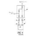
原料容器と密接に熱接触するガスパネル
図4〜図6は、3つの異なるガスパネル機構を示す。ガスパネルは通常、前駆体原料容器の下流にある1つ又は複数の弁を含み、容器の上流にも1つ又は複数の弁を含むことができる。図4は、原料化学物質が原料容器10内に収容される従来の機構を示す。ガスパネル90は、キャリアガス供給源(図示せず)から容器10を通して反応チャンバ(図示せず)にキャリアガスを送出するように動作可能な複数の弁を含む。入口弁91が、配管93によって容器10の上流に接続され、出口弁92が、配管94によって容器10の下流に接続される。この従来の機構では、入口弁91、出口弁92、並びにガスパネル90の弁及び配管は通常、容器10と密接に熱接触していない。Gas panel in intimate thermal contact with the source vessel FIGS. 4-6 show three different gas panel mechanisms. The gas panel typically includes one or more valves downstream of the precursor source vessel and can also include one or more valves upstream of the vessel. FIG. 4 shows a conventional mechanism in which the raw chemical is contained in the
図5は、図4の機構に対して幾分改善されている機構を示す。図5の機構では、前駆体原料容器100が、表面実装入口弁108及び表面実装出口弁110を有する。弁108及び110は、配管95及び96によって従来のガスパネル90から分離される。この機構では、弁108及び110は、容器100と密接に熱接触しているが、ガスパネル90の弁及び配管はそうではない。 FIG. 5 shows a mechanism that is somewhat improved over the mechanism of FIG. In the mechanism of FIG. 5, the
図6は、図5の機構に対して改善されている機構を示す。図6の機構では、原料容器100は、表面実装入口弁108及び表面実装出口弁110を備える概ね平坦な上面を有する。また、ガスパネル97が、ガスパネルの弁及び配管が容器100の概ね平坦な表面とほぼ平行な平面に沿って位置決めされるように配置される。容器100とガスパネルの弁及び配管との熱接触を高めるために、ガスパネルの弁及び配管の平面と容器100の概ね平坦な表面との間の距離は、好ましくは約10.0cm以下、より好ましくは約7.5cm以下、さらにより好ましくは約5.3cm以下である。 FIG. 6 shows an improved mechanism over the mechanism of FIG. In the mechanism of FIG. 6, the
表面実装弁及び蛇行経路を有する原料容器
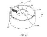
図7は、改良型の固体又は液体前駆体原料容器100及びクイック接続アセンブリ102の好適な実施形態を示す。原料容器100は、コンテナ本体104及び蓋106を含む。蓋106は、より詳細に後述する表面実装隔離弁108及び110を含む。Source Container with Surface Mount Valve and Serpentine Path FIG. 7 illustrates a preferred embodiment of an improved solid or liquid
図8〜図10は、図7の原料容器100をより詳細に示す。図8は、原料容器100の分解図であり、図9及び図10は、原料容器100の後部断面図である。図示の容器100は、コンテナ本体104、本体104内の蛇行経路インサート112、及び蓋部品106を含む。図示のアセンブリは、ねじ又はナット及びボルトの組み合わせ等の締結要素124によって互いに締結される。締結要素124は、本体104のフランジ126内の整列した孔に入るようになっている。様々な代替的な方法によってアセンブリを互いに締結できることが、当業者には理解されるであろう。 8 to 10 show the
蛇行経路インサート112は、キャリアガスが容器100を流れるときに進まなければならない迂曲又は蛇行経路111を画定することが好ましい。蛇行経路112は、粉末又は液体等の前駆体原料を収容することが好ましい。キャリアガスを前駆体原料に曝しながら長い蛇行経路111に流すことで、キャリアガスがより多くの反応物蒸気を運ぶようになる。蛇行経路111は、従来の前駆体原料容器内のキャリアガス流路よりも著しく長い。キャリアガスは、前駆体原料と曝されながら長い経路に沿って流れる必要があるため、より長い時間にわたって前駆体原料に曝されることで前駆体でより飽和されやすくなる。キャリアガスが曝されるようになる反応化学物質及び滞留時間が増えるため、蛇行経路111は、処理中に容器100を加熱する重要性も減らし、その実際的な効果として、昇華/気化に要する温度が低下する。弁108及び110(後述)及び弁210(図25〜図28を参照して後述)は、あまり厳しい環境下にないため信頼性が高まる。低い温度要件により、設計における部品の選択肢も増える。十分な量の反応物蒸気を反応チャンバに送出することが容易になるため、性能も向上する。また、ALD処理中の各反応物パルスの濃度は、時変性が小さくなる。換言すれば、キャリアガスが反応物蒸気で完全な飽和状態に近付くにつれて、反応物パルス波形は直線的な波に近くなる。 The serpentine path insert 112 preferably defines a circumflex or
蛇行インサート112を蓋106に対して付勢して、インサート112と蓋106との間の境界面から反応物ガスが逃げるのを防止するために、ばね114を設けることが好ましい。換言すれば、ばね114は、蛇行経路の一部又は全部をガスが迂回する危険を減らす傾向がある。適当なばね114は、イリノイ州レイクズーリックのSmalley Steel Ring Companyから販売されているSpirawave(登録商標)波形ばね等の平角線圧縮ばねを含む。 A
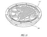
代替的な実施形態では、蛇行経路111は、コンテナ本体104又は容器蓋106に直接加工される。例えば、図11は、一体形成の蛇行経路111が直接加工されているコンテナ本体104を示す。 In an alternative embodiment, the
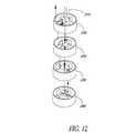
図12〜図16に示す別の代替的な実施形態では、蛇行インサート112は、蛇行ガス流路を共同で画定する複数の積み重ねたトレーを備える。例えば、図12は、複数の積み重ねられるトレー230、240を示しており、これらは、コンテナ本体104(図7〜図10)に取り外し可能に挿入されるように構成され、容器100の迂曲経路の少なくとも一部を含む螺旋状ガス流路を共同で画定する。図12〜図16では、説明を容易にするためにトレー230、240の高さを増加してある。容器100の直径がその全高よりも大幅に大きくなるように、トレーを鉛直方向により薄くしてもよいことを理解されたい。 In another alternative embodiment shown in FIGS. 12-16, the
図示の実施形態では、4つのトレー、すなわち3つの上トレー230及び1つの下トレー240が積み重ねられる。トレーの数は、昇華速度、キャリア流等のパラメータに基づいて変わり得る。 In the illustrated embodiment, four trays, three
図13及び図14を参照すると、各上トレー230は、ガス流の通過を防止すると共にトレー230の全高に延びる完全(solid:隙間のない)ディバイダ231と、ガス流の通過を許す部分ディバイダ232とを含む。好ましくは、部分ディバイダは、ガス流の自由な通過を許したまま大きな前駆体微粒子を保持するように構成されるスクリーン233を含む。図示の実施形態では、スクリーン233は部分ディバイダ232の上部にわたって延びているが、部分ディバイダ232の高さは中実パネルで終わっている。環状リム234も上トレー230の高さに延びる。完全ディバイダ231及び部分ディバイダ232は共に、固体原料材料(図示せず)を保持する主区画235及びトレー230の下面で開いている外側チャネル区画236を画定する。図示の上トレー230は、下トレー240にキャリアガスを送出するガス入口パイプを収納するための中央チャネル238を含む中央コア237を有する。図示の上トレー230は、上面には複数のペグ239、及び下面にはその下の別のトレーのペグを受け入れる対応の複数の孔(図示せず)も有する。本明細書で後述する動作に照らすとよりよく理解されるように、中央コア237の下面の孔は、上面のペグ239に対して回転方向にずれていることで、曲がりくねった流路を画定するように複数のトレーを互いに重ねて適切に位置合わせする役割を果たすことが望ましい。いくつかの好適な実施形態では、流れが曝される主区画のコーナには、鋭角のコーナからの流れの停滞を最小限に抑えるために丸みが付けられる。 Referring to FIGS. 13 and 14, each
図15及び図16を参照すると、最下部のトレー240は、ガス流の通過を防止すると共にトレー240の全高に延びる完全ディバイダ241と、ガス流の乗り越えを許す部分ディバイダ242とを含む。好ましくは、部分ディバイダ242は、図12の説明に照らすとよりよく理解されるように、上に重なった上トレー230の中央にある中央チャネル238に通じる開口を提供するだけである。環状リム244も下トレー240の高さに延びる。リム244、完全ディバイダ241、及び部分ディバイダ242は共に、固体原料材料(図示せず)を保持する主区画245及び外側チャネル区画246を画定する。好適な実施形態では、固体原料材料は、主区画245を完全に満たしてさらにはチャネル区画246も満たす。代替的な実施形態では、固体原料材料は、主区画の高さの1/3〜2/3を満たす。図示の下トレー240は、チャネル区画246が突入している中央コア247、上面には複数のペグ249、及び下面にはコンテナ本体104(図7〜図10)の床から上方に突出するペグを受け入れる対応の複数の孔(図示せず)も有する。 Referring to FIGS. 15 and 16, the
トレー230、240のスタックは、図12の分解図に示すように組み立てられる。上トレー230及び下トレー240それぞれの主区画235、245には、好ましくは粉末の形態の前駆体原料化学物質が充填される。下トレー240及び複数の上トレー230は、互いに積み重ねて外部のコンテナ本体104に装填される。トレー230、240は、ガスが各トレーに流れ込んで、好ましくは少なくとも主区画を200度〜355度回って流れてから上に重なった上トレー230のチャネル区画236に入るように、ペグ239、249及び対応の孔によって位置合わせされる。続いて、コンテナ蓋106(図7及び図8)がコンテナ本体104の上で閉じられてシールされ、蓋から延びる中央パイプ215が、上トレー230の中央チャネル238を下方に貫通して下トレー240のチャネル区画246に通じる。図12は、中央パイプ215を示しているが蓋106は示していない。中央パイプ215は、搬送されるキャリアガスを容器100の入口に送出するように構成される。いくつかの好適な実施形態では、多くの場合、ばね又は他の付勢デバイス(図示せず)が下トレー240の下に配置されて全てのトレーを互いに付勢することで、中央コアから異なるレベルへの漏れを防止する。 The stack of
動作の際、トレー230、240のスタックに不活性ガスを送出することが好ましく、不活性ガスは、好ましくは各トレー230、240の主区画の約200度〜350度の円弧を水平方向に通った後でそのトレーから鉛直方向に出る、長く曲がりくねった流れルートを経る。図示の実施形態では、不活性キャリアガスは、上トレー230の位置合わせされた中央チャネル238を下方に貫通して下トレー240のチャネル区画246に通じる中央入口215を通して供給される。不活性ガスは、上に重なった上トレー230の下面の開口に達するまで、主区画245内の前駆体原料化学物質を通過しながら曲進する。この開口は、キャリアガス及びそれが運ぶ気化した前駆体が上に重なった上トレー230のチャネル区画236に入ることを可能にし、ガスは、チャネル区画236からスクリーン233(図13)を通過して主区画235に入る。ガスは、その主区画235内の固体前駆体を通過して、好ましくは約200度〜350度の円弧を曲進した後で、上に重なった上トレー230の下面の開口に達し、以下同様である。最上部の上トレー230において、ガスは、好ましくは蓋容器106の表面実装出口弁110(後述)を通って容器100から出ることができる。当然ながら、所望であれば流路を逆にしてもよいことを理解されたい。換言すれば、不活性キャリアガスは、最上部トレーから始まってトレーのスタックを流れ下りることができる。 In operation, it is preferable to deliver an inert gas to the stack of
図8〜図10を再び参照すると、図示の実施形態では、容器蓋106は、入口弁108及び出口弁110を含む。入口弁108は、導管121を介してキャリアガスを受け取る入口端を有する。導管121は、ガスインタフェースアセンブリ180(後述)のガスライン133のフィッティング131(図7)に接続するようになっているフィッティング122を有する。入口弁108は、インサート112の蛇行経路111の第1の部分117(端部等)と流体連通することが好ましい出口端も有する。出口弁110は、蛇行経路111の第2の部分119(端部等)と流体連通することが好ましい入口端、及びオリフィス128等の蓋106の適当なガス出口と流体連通する出口端を有する。使用の際、キャリアガスは、導管121に流れ込み、入口弁108、蛇行経路111、及び出口弁110を通った後でオリフィス128から出る。したがって、この実施形態によって達成され得る結果は、蓋106の表面に隔離弁を取り付けること、及びキャリアガスを前駆体原料に曝しながら迂曲又は蛇行経路に沿って流すことを含む。容器100を異なる構成にしてもよいことが、当業者には理解されるであろう。 Referring again to FIGS. 8-10, in the illustrated embodiment, the
上述したように、従来の固体又は液体前駆体原料容器は、容器本体又は蓋から延びる別個の管を含み、弁がこのような管とインラインで取り付けられている。例えば、図2の従来の容器31は、蓋35から上方に延びる別個の管43b及び45bを含み、弁37及び39がこのような管に取り付けられている。容器37の弁37及び39は、蓋35に直接取り付けられてもおらず接触もしていない。その結果、容器31からの反応物ガスが出口管45bから流れ出てから出口弁39に流れ込むことで、流路にガスの停滞又はデッドボリュームが伴い得る。さらに、従来の容器31の隔離弁37、39、及び41は、容器の蓋35及び本体33から大きく熱的に隔離されている。配管及び弁のいずれも、デッドボリューム又は「デッドレッグ」の有無に関係なく、3次元幾何形状で効果的に加熱することが非常に困難である。弁は、蓋35及び本体33よりも熱質量が小さいため、急速に加熱及び冷却される傾向がある。従来のシステムにおいて、システム冷却時に弁及び関連の配管に熱を与えて、このような部品が容器31よりも速く冷却される(反応物蒸気がこのような部品に流れ込んでそこに堆積するという望まれない状況を生む可能性がある)のを防止するために、付加的なヒータ(ラインヒータ、カートリッジヒータ、直接加熱ランプ(directed heat lamp)等)が多くの場合に特に用いられるのは、こうした理由からである。従来の弁及び配管に関する別の問題は、これらが容器31よりも速く加熱され得ることである。前駆体によっては、これにより、弁及び配管が前駆体の分解温度よりも高くなることで前駆体を分解してそこに堆積させるという状況が生まれる可能性がある。 As described above, conventional solid or liquid precursor source containers include a separate tube extending from the container body or lid, with a valve attached inline with such a tube. For example, the
対照的に、原料容器100の隔離弁108及び110(図7〜図10)は、容器100の蓋106の表面に直接備え付けられることが好ましい。このような表面実装技術は、集積ガスシステムと呼ばれ得る。従来の前駆体原料容器(例えば、図2)と比較して、表面実装弁108及び110は、弁と容器100との間の配管をなくして反応物ガスの移動経路を単純化及び短縮することによってガス送出システムのデッドレッグ(反応物ガス流の停滞)の体積を減らすことができる。これらの弁及び配管は、幾何形状が圧縮され熱接触が改善されたことによってはるかに加熱されやすくなるため、温度勾配が小さくなる。図示の表面実装弁108及び110は、弁ポーティングブロック(valve porting block)118及び120をそれぞれ有し、これらは、弁座と、弁座を通るガス流を選択的に制御する調整可能なフローリストリクタ(例えば、ダイヤフラム)とを含むことが好ましい。このような弁108及び110は、弁座を通る全ガス流を制限することによって容器100を隔離する。ポーティングブロック118、120は、容器蓋106と一体形成されてもよく、又は容器蓋106と別個に形成されて容器蓋106に備え付けられてもよい。いずれの場合も、ポーティングブロック118、120は、容器蓋106と比較的高い熱接触度を有することが好ましい。これにより、容器100の温度変化時に弁108及び110の温度が蓋106及びコンテナ本体104の温度に近いままとなる。この表面実装弁構成で、気化した前駆体ガスの凝縮を防止するのに必要なヒータの総数を減らすことができる。容器100が前駆体原料化学物質の気化温度よりも高い場合、気化した前駆体は、弁108及び110に自由に流れることができる。弁108、110は、温度ランピング時に容器100の温度を厳密に辿るため、弁も気化温度より高くなる可能性が高いことで、弁における前駆体の凝縮を防止するための付加的なヒータの必要が減る。短縮されたガス流路も加熱の制御に適している。表面実装弁108及び110は、実装空間要件もはるかに小さい。 In contrast, the
弁108及び110はそれぞれ、弁によって制限又は開放することができるガス流路を含む弁ポーティングブロックを備えることが好ましい。例えば、図9及び図10を参照すると、弁108のポーティングブロック118は、導管121からポーティングブロック118の片側123を通って領域113まで延びる内部ガス流路を含むことが好ましい。領域113は、弁座及び可動リストリクタ又はダイヤフラム等、ガスの流れを制限する内部装置(図示せず)を含むことが好ましい。一実施形態では、可動内部リストリクタ又はダイヤフラムは、ノブ(例えば、弁108のより大きな円筒形上部181)を手動又は自動で回すことによって動かすことができる。別の内部ガス流路が、領域113からブロック118の反対側125を通って、蓋106を貫通して容器100内に通じる入口通路まで延びることが好ましい。例えば、入口通路は、蛇行インサート112によって画定される迂曲経路111まで延び得る。弁110及びベント弁210(図25〜図28を参照して後述)は、弁108と同様に構成され得る。一実施形態では、弁108及び110は空気弁である。弁ポーティングブロック118及び120を容器蓋106と一体形成することが特に好ましい。これにより、両者間の別個のシールの必要がなくなる。 Each of the
別の実施形態では、弁108、110、及び210(図25〜図28)は、ポーティングブロック118、120等のポーティングブロックを有せずに形成され、容器蓋106等の容器100の一部と一体形成されることが好ましい。 In another embodiment, the
フィルタ
好ましくは、前駆体原料容器は、粒子状物質(例えば、原料化学物質の粉末)が容器から逃げるのを防止するために、容器を通るガス流を濾過する濾過装置を含む。濾過装置は、容器の蓋に、好ましくは表面実装弁108、110、及び/又は210(図25〜図28)の下に設けられ得る。好ましくは、濾過装置は、容器の入口及び出口ごとに別個のフィルタを備える。Filter Preferably, the precursor source vessel includes a filtration device that filters the gas flow through the vessel to prevent particulate matter (eg, source chemical powder) from escaping from the vessel. A filtration device may be provided on the container lid, preferably under the
図17は、反応物原料容器の本体又は蓋(例えば、図8の蓋106)に装着され得る濾過装置130の一実施形態の断面図である。図示の装置130は、フランジ132、フィルタ媒体134、及びファスナ要素136から成るフィルタである。この実施形態では、フィルタ130は、容器の蓋(例えば、図8の蓋106)の凹部138に密接に嵌まるようなサイズ及び形状である。フランジ132の外周は、円形、矩形、又は他の形状とすることができ、その形状は、凹部138の外周にぴったりと一致することが好ましい。フィルタ材料134は、フランジ132の環状内壁140によって画定される開口を通る特定サイズよりも大きなガス混入粒子の通過を制限するように構成される。材料134は、壁140によって画定される開口全体を遮断することが好ましい。材料134は、様々な異なる材料のいずれを含んでいてもよく、一実施形態では高流動性の焼結式ニッケル繊維媒体(high flow sintered nickel fiber media)である。他の実施形態では、フィルタ媒体は、他の金属(例えば、ステンレス鋼)、セラミック(例えば、アルミナ)、石英、又はガス若しくは液体フィルタに通常組み込まれる他の材料から製造される。材料134は、環状壁140に溶接又は接着されることが好ましい。一実施形態では、フィルタ130は、カリフォルニア州サンタクララのTEM Productsから販売されているもの等の表面実装サンドイッチフィルタを含む。 FIG. 17 is a cross-sectional view of one embodiment of a
図示の実施形態では、ファスナ要素136は、フランジ132を蓋106の壁146に対して付勢するばねスナップリングを含む。リング136は、凹部138の外周の環状凹部142内に密接に嵌まることが好ましい。スナップリング136は、例えば、イリノイ州レイクズーリックのSmalley Steel Ring Companyから販売されているSpirawave(登録商標)波形ばね等の平角線圧縮ばねを含み得る。フィルタ130を蓋106に締結するために、さらなる異なるタイプの締結要素を設けてもよい。好ましくは、ファスナ要素136は、フランジ132と蓋106との間の境界面を通ってキャリアガス及び反応物蒸気が流れるのを防止することで、全てのガスがフィルタ材料134を通って流れなければならないようにする。フィルタ130の出口側にプレナム148を画定するために副凹部147が設けられ得ることで、濾過されたガス流の品質を改善することができる。図示のフィルタ130は、単にスナップリング136を環状凹部142から取り外し、フィルタ130を凹部138から取り外し、新たなフィルタ130を挿入して、スナップリング136を環状凹部142に挿入し戻すことによって、容易に交換可能である。 In the illustrated embodiment, the
フィルタ凹部138は、前駆体原料容器の隔離弁の1つに近接して位置付けられることが好ましい。図17の実施形態では、凹部138は、原料容器100の出口隔離弁110(図1)の弁ポーティングブロック120の直下にある。個々のフィルタ130が入口弁108及びベント弁210(図25〜図28)を含む容器の各隔離弁に関連して設けられ得ることが、当業者には理解されるであろう。プレナム148から弁ポーティングブロック120の通路144まで、通路145が延びる。図示の実施形態では、ポーティングブロック120は、容器蓋106とは別に形成され、両者間にシールが設けられることが好ましい。別の実施形態では、ブロック120は、蓋106と一体形成され、通路144、145は、同じ穿孔作業で形成される。
図18は、一実施形態によるフィルタ材料134の表面部分の拡大断面図である。この実施形態では、フィルタ材料134は、大粒子濾過層150及び小粒子濾過層152を含む。大粒子濾過層150は、比較的大きな粒子を濾過することが好ましく、小粒子濾過層152は、比較的小さな粒子を濾過することが好ましい。大粒子濾過層150は、複数の空隙151を含む。一実施形態では、大粒子濾過層150は、約20%〜60%の空隙率、より好ましくは30%〜50%の空隙率である。一実施形態では、大粒子濾過層150は、約42%の空隙率である。大粒子濾過層150は、例えばステンレス鋼材料を含み得る。大粒子濾過層150は、フィルタ材料134の大部分を構成することが好ましい。空隙151があるため、フィルタ材料134で生じる圧力損失は比較的小さい。大粒子濾過層150の構造剛性を高めるために、1つ又は複数の支持管154が設けられ得る。小粒子濾過層152は、0.05ミクロン〜0.2ミクロンの孔径、より好ましくは約0.10ミクロンの孔径を有し得る。小粒子濾過層152は、約5ミクロン〜20ミクロン、より好ましくは約10ミクロンの厚さを有し得る。小粒子濾過層152は、例えばジルコニアのコーティングを含み得る。大粒子濾過層150の各側が、小粒子濾過層152で被覆され得る。適当なフィルタ材料は、Pall Corporationから販売されているAccuSepフィルタと同様のものである。 FIG. 18 is an enlarged cross-sectional view of a surface portion of
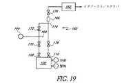
ガスインタフェースアセンブリ
図19は、前駆体原料容器100及び気相反応チャンバ162にキャリアガス及び反応物ガスを流すために用いられ得るガス送出システム160の概略図である。本明細書で説明するように、送出システム160は、容器100、キャリアガス供給源164、下流清浄器又はフィルタ166、及び複数の付加的な弁を含む。隔離弁108、110は、上述のように容器100に表面実装されることが好ましい。キャリアガス供給源164は、接続点168に不活性キャリアガスを送出するように動作可能である。弁170が、接続点168と容器入口弁108との間に介装される。弁172が、接続点168と接続点174との間に介装される。弁176が、接続点174と容器出口弁110との間に介装される。清浄器166及び付加的な弁178は、接続点174と反応チャンバ162との間に介装される。図示のように、容器100は、適当な制御及び警報インタフェース、ディスプレイ、パネル等を有し得る。Gas Interface Assembly FIG. 19 is a schematic diagram of a gas delivery system 160 that may be used to flow carrier and reactant gases through the
容器100を通して反応チャンバ162にキャリアガスを流すことが望ましい場合、弁170、108、110、176、及び178を開いて弁172を閉じる。反対に、キャリアガスが反応チャンバ162への途中で容器100を迂回することが望ましい場合、弁172及び178を開き、好ましくは弁170、108、110、及び176の全てを閉じる。例えば保守及び修理のために、弁178を用いて、反応チャンバ162をガス送出システム160から隔離することができる。 If it is desired to flow carrier gas through the
図7を再び参照すると、容器100及び関連の気相反応チャンバを通るキャリアガス及び反応物蒸気の流れの制御を容易にするガスインタフェースアセンブリ180において、前駆体ガス送出システム(図19に示すもの等)を具現することができる。図示のガスインタフェースアセンブリ180は、複数の弁182(図19の弁170、172、176、及び178と実質的に同じ機能を果たすことができる)、下流清浄器又はフィルタ184、及びヒータプレート186を含む。弁182は、弁ポーティングブロック118及び120と原理及び動作が同様である弁ポーティングブロック188を含み得る。 Referring again to FIG. 7, in a
図7及び図19を参照すると、ガスライン133が、キャリアガス供給源164からキャリアガスを受け取る弁182の1つから延びる。例えば、ガスライン133が延びている弁182は、実質的に図19の弁170の機能を果たすことができる。図7は、キャリアガス供給源からこのような弁まで延びるガスラインを示していないが、設けられることを理解されたい。ガスライン133は、容器100とガスインタフェースアセンブリ180とが接続されるときに容器のキャリアガス入口フィッティング122に接続するフィッティング131を含む。ガスインタフェースアセンブリ180の出口135が、反応チャンバ162にガスを送出する。原料容器のキャリアガス入口は、出口オリフィス128と同様に構成され得ることを理解されたい。 Referring to FIGS. 7 and 19, a
図7を引き続き参照すると、ヒータプレート186は、弁182及び容器100を好ましくは前駆体の気化温度よりも高い温度に加熱する。好適な実施形態の様々な弁と、弁ポーティングブロックと、ガス導管とが高度に熱接触すること、及びヒータプレート186がこれらの部品に近接していることで、容器100の下流のガス搬送部品における前駆体の凝縮を防止するのに必要な総熱量が減る。ヒータプレート186は、カートリッジヒータ又はラインヒータ等の様々な異なるタイプのヒータによって加熱され得る。ヒータプレートは、アルミニウム、ステンレス鋼、チタン、又は様々なニッケル合金等の様々な材料から形成され得る。サーモフォイル型ヒータを用いて、ヒータプレート186及び弁ポーティングブロック188を加熱することもできる。サーモフォイル型ヒータを用いることで、可変ワット密度又は2つ以上の制御ゾーンが可能になり得る。可変ワット密度又は複数の温度制御ゾーンがヒータプレート186に組み込まれることで、ガスの流路に沿って温度勾配をつけることが可能になり得る。これにより、反応物蒸気が下流に移動するにつれて徐々に加熱されるようにすることができるため、凝縮が回避される。適当なサーモフォイルヒータは、ミネソタ州ミネアポリスのMincoから販売されている。容器蓋106及びコンテナ本体104を加熱するために、付加的なヒータ(ラインヒータ、カートリッジヒータ、放射加熱ランプ、及びサーモフォイル型ヒータを含む)を設けることもできる。 With continued reference to FIG. 7, the
いくつかの実施形態では、容器100を加熱するために専用のヒータが設けられ得る。図18に示す特定の一実施形態(さらに詳細に後述する)では、専用の加熱デバイス220が容器のコンテナ本体104の下面の下に設けられる。 In some embodiments, a dedicated heater may be provided to heat the
上述のように、前駆体蒸気は、「ベーパードロー」法及び外部ガス流法によって容器100から引き抜くこともできる。ベーパードロー法では、蒸気を引き出すために容器100が真空引きされる。例えば、弁110、176、及び178を開いて弁108、170、及び172を閉じた状態で、反応チャンバ162が下流から真空引きされ得る。真空引きは、例えば真空ポンプを用いて行うことができる。外部ガス流法では、前駆体蒸気は、弁110、172、176、及び178を開いて弁108及び170を閉じた状態で供給源164から反応チャンバ162にキャリアガスを流すことによって、容器100から引き抜かれ得る。或る条件下では、これが容器100とキャリアガスの流路との間に差圧を発生させることで、前駆体蒸気を反応チャンバに向かって流すことができる。 As described above, the precursor vapor can also be withdrawn from the
クイック接続アセンブリ
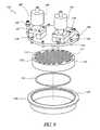
図7を引き続き参照すると、クイック接続アセンブリ102は、ガスインタフェースアセンブリ180への前駆体原料容器100の迅速で容易な装填、位置合わせ、及び接続を促すことが好ましい。クイック接続アセンブリ102は、人間工学的に優しく、容器100の交換及び再充填を容易にして保守性を高める。これらの目標に留意して、様々な異なるタイプのクイック接続アセンブリを提供することができ、図示のアセンブリ102が一実施形態にすぎないことが、当業者には理解されるであろう。クイック接続アセンブリ102は、原料容器100及び支持制御ハードウェアが実装される真空エンクロージャに組み込まれ得る。Quick Connect Assembly With continued reference to FIG. 7, the
図7、図20、及び図21を参照すると、図示のクイック接続アセンブリ102は、ベース190、ベース190の縁から上方に延びるペデスタル192、トラック部品194、及びリフトアセンブリ196を含む。ベース190は、反応物原料キャビネット16の床9等、ガス送出システム6(図1)の下内面に固定され得ることが好ましい。好ましくは、ペデスタル192は、ベース190の上方の位置でガスインタフェースアセンブリ180に接続されてこれを支持する。トラック部品194は、プラットフォーム198及びプラットフォーム198の両側にある2つのローラトラック200を含む。整列したローラ204を有する一対のローラアセンブリ202が、容器100の両側に固定されることが好ましい。この実施形態では、ローラ204は、トラック部品194のトラック200内で転動するようなサイズ及び構成であるため、容器100をプラットフォーム198に容易且つ迅速に位置決めすることができる。 With reference to FIGS. 7, 20, and 21, the illustrated
ローラアセンブリ200をトラック200と係合させて容器100をプラットフォーム198に搭載すると、出口弁100の出口が、ガスインタフェースアセンブリ180の弁182の1つの入口と鉛直方向に位置合わせされることが好ましい。リフトアセンブリ196は、プラットフォーム198を下降位置(図7に示す)と上昇位置(図20及び図21に示す)との間で鉛直方向に移動させるように構成される。容器100をプラットフォーム198に搭載してプラットフォームをその上昇位置に移動させると、出口弁110の出口が、弁182の1つの入口と直接的又は間接的に連通することが好ましい。出口弁110の出口と弁182の入口との間の境界面を適切にシールするために、最小限の手動調整が必要となり得る。図示の実施形態では、出口弁110の出口は、弁ポーティングブロック120のオリフィス128である。このように、クイック接続アセンブリ102は、前駆体原料容器100とガスインタフェースアセンブリ180との迅速な接続を可能にする。 When the
図20に示すように、図示のリフトアセンブリ196は、プラットフォーム198を鉛直方向に移動させるようにシザーレッグ197を手動で作動させることができるリフトハンドル195を備える。例えば、ハンドル195及びレッグ197は、何らかの既存のオートジャッキと同様に動作することができる。一実施形態では、リフトアセンブリ196は、ハンドル195を約180度回転させるとプラットフォーム198をその上昇位置に持ち上げる。しかしながら、他のタイプのリフトデバイスを代替的に設けてもよいことを理解されたい。 As shown in FIG. 20, the illustrated
クイック接続アセンブリ102は、空になった容器100を新たな容器と交換することをより容易にする。さらに、アセンブリ102が容器の取り外し及び装着を単純化するため、容器100の日常保守もより行いやすい。好ましくは、容器100の重量は、一人の技術者で容易に対処できるようなものである。 The
図22〜図24は、クイック接続アセンブリ102の代替的な実施形態を示す。図示のアセンブリ102は、プラットフォーム198及びペデスタル192を含む。プラットフォーム198は、容器100の両側に取り付けられる舌部206を受け入れるようになっているトラック200を含む。プラットフォーム198を上昇させるために、1つ又は複数のリフトデバイス208が設けられる。図示の実施形態では、リフトデバイス208は、プラットフォーム198の下のボルトを含む。ボルトを回して、プラットフォーム198を容器100に関連する接続位置に上昇させることができる。プラットフォーム198の鉛直方向位置合わせを維持するために、ガイド装置(図示せず)が設けられ得る。 22-24 show an alternative embodiment of the
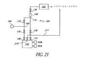
ベント弁
上述のように、前駆体原料容器には通常、容器内に不活性ガス(例えば、ヘリウム)のヘッド圧が加えられる。このヘッド圧を抜いて通常のプロセス圧まで下げる間に、固体前駆体粒子は、エアロゾル化して不活性ガス流出流中に混入する。このようなガスは通常、容器の出口隔離弁、反応物ガス送出システム、及び最終的に反応器のイグゾースト/スクラバを通して抜かれるため、これはガス送出システムを汚染し得る。その後、基板処理中に、前駆体送出経路とベント経路とに共通であるガスパネルの汚染部分が、基板上のALD中に処理不良を引き起こし得る。Vent Valve As described above, a head pressure of an inert gas (for example, helium) is usually applied to the precursor raw material container. While the head pressure is released and reduced to the normal process pressure, the solid precursor particles are aerosolized and mixed into the inert gas effluent. Because such gases are typically vented through the vessel outlet isolation valve, the reactant gas delivery system, and ultimately the reactor exhaust / scrubber, this can contaminate the gas delivery system. Subsequently, during substrate processing, contaminated portions of the gas panel that are common to the precursor delivery path and vent path can cause processing failures during ALD on the substrate.
好適な実施形態では、この問題は、処理前に容器内のガスのヘッド圧を解放するために前駆体原料容器に付加的なベント弁を設けると共にガス送出システムに専用のベントラインを設けることによって、実質的に克服される。図25〜図28は、本発明のこの態様の一実施形態を示す。図25は、容器ベント弁210が前駆体原料容器100に加えられていると共に専用ベントライン211がベント弁210に接続されている、図19のガス送出システム160の概略図である。図示のベントライン211は、イグゾースト/スクラバまで直接延びる。抜かれたガスは、部品110、176、166、178、又はそれらの間のガスライン等、反応チャンバ162への前駆体送出の経路を形成するガス送出システムを汚染することなく、実質的に放出させることができる。 In a preferred embodiment, this problem is solved by providing an additional vent valve in the precursor feed vessel and a dedicated vent line in the gas delivery system to relieve the gas head pressure in the vessel prior to processing. Is substantially overcome. Figures 25-28 illustrate one embodiment of this aspect of the invention. FIG. 25 is a schematic diagram of the gas delivery system 160 of FIG. 19 with a
容器ベント弁210に表面実装フローリストリクタを加えてベント流速度を低下させることで、前駆体原料(例えば、粉末)をかき乱す可能性がある乱流を減らすことができる。適当な表面実装フローリストリクタは、コネチカット州ファーミントンのMott Corporationから販売されており、GSMRリストリクタとしても知られている。 By adding a surface mount flow restrictor to the
図26は、ベント弁210を含む前駆体原料容器100の一例を示す。この実施形態では、ベント弁210は、入口隔離弁108及び出口隔離弁110の中間に位置決めされている。しかしながら、他の配置が可能であることが、当業者には理解されるであろう。好ましくは、ベント弁210は、弁ポーティングブロック118及び120と実質的に同様であり得る弁ポーティングブロック212を含む。図27は、上述のように図22〜図24のガスインタフェースアセンブリに接続される図26の容器100を示す。 FIG. 26 shows an example of the precursor
図28は、図26の容器100の実施形態の断面図である。上述のように、容器100は、コンテナ本体104、蛇行インサート112、ばね114、及び容器蓋106を含む。容器蓋106は、表面実装隔離弁108及び110、並びに好ましくは表面実装の隔離弁210を含む。好ましくは、弁108、110、及び210は、弁ポーティングブロック118、212、及び120をそれぞれ含む。図28は、弁ポーティングブロックの内部ガス通路214も示す。上述のように、弁ポーティングブロック120は、ガスインタフェースアセンブリ180に前駆体蒸気及びキャリアガスを供給するガス出口128を含む。 FIG. 28 is a cross-sectional view of the embodiment of the
弁108、210、及び110のそれぞれにフィルタが関連付けられることが好ましい。図示の実施形態では、容器蓋106は、各弁に関連するフィルタ130(例えば、図17に示し上述したような)を含む。様々な異なるタイプのフィルタを用いることができることを理解されたい。フィルタは、前駆体粒子が容器100から出るのを防止する。 A filter is preferably associated with each of the
いくつかの実施形態及び例に関して本発明を開示したが、本発明が具体的に開示した実施形態を超えて他の代替的な実施形態並びに/又は使用及び自明の変形形態並びにその均等物にまで及ぶことが、当業者には理解されるであろう。したがって、本発明は、本明細書中の好適な実施形態の具体的な開示によって限定されることは意図されない。 Although the invention has been disclosed with respect to several embodiments and examples, the invention extends beyond the specifically disclosed embodiments to other alternative embodiments and / or uses and obvious variations and equivalents thereof. It will be appreciated by those skilled in the art. Accordingly, the present invention is not intended to be limited by the specific disclosures of preferred embodiments herein.
Claims (9)
Translated fromJapanese入口及び出口を含み、固体又は液体化学反応物を収容するようになっている内部チャンバを画定する容器本体であって、前記チャンバは、前記化学反応物を収容するように構成される迂曲経路を含み、該迂曲経路は、前記入口から前記出口まで延びる、容器本体と、
前記容器本体内にあり、該容器本体の外側から容器チャンバまで延びる入口通路と、
前記容器本体の表面に直接取り付けられ、前記入口通路を通る流れを調整するように構成される入口弁と、
前記容器本体内にあり、前記容器チャンバから前記容器本体の外側まで延びる出口通路と、
前記容器本体の表面に直接取り付けられ、前記出口通路を通る流れを調整するように構成される出口弁と、
基板を処理する気相反応チャンバと、
前記容器を通じて前記気相反応チャンバへキャリアガスを輸送するように共同して動作可能であり、少なくとも一つのガスパネル弁が前記出口と前記反応チャンバとの間に流体挿入される複数のガスパネル弁と、
を備え、
全ての前記ガスパネル弁は、前記容器本体の表面から10.0cm以内に位置しており、
前記入口弁及び前記出口弁は、それぞれ前記入口弁及び前記出口弁と前記容器本体の前記表面との間で配管を用いずに前記容器本体の前記表面に接続される、化学反応物原料容器及びガス送出システムの結合体。Aconjugate of agas delivery system and chemical reactant source vesselfor the gas-phase reactor for processing a substrate,
A container body that includes an inlet and an outlet and defines an internal chamber adapted to receive a solid or liquid chemical reactant, the chamber having a detour path configured to receive the chemical reactant And the detour path extends from the inlet to the outlet, and a container body;
Aninlet passage in thecontainer body and extending from the outside of thecontainer body to thecontainer chamber;
Aninlet valve attached directly to a surface of the container body and configured to regulate flow through theinlet passage;
An outlet passage in the container body and extending from the container chamber to the outside of the container body;
An outlet valve attached directly to a surface of the container body and configured to regulate flow through the outlet passage;
A gas phase reaction chamber for processing a substrate;
A plurality of gas panel valves operable jointly to transport carrier gas through the vessel to the gas phase reaction chamber, wherein at least one gas panel valve is fluidly inserted between the outlet and the reaction chamber When,
Equipped witha,
All the gas panel valves are located within 10.0 cm from the surface of the container body,
It said inlet valve and said outlet valve is connected to the surface of the container body without using a pipe between each of the inlet valve and the outlet valve and the surface of the container main body, a chemical reactant source vesseland Combined gas delivery system .
前記容器本体に備え付けられるか又は該容器本体と一体形成される弁ポーティングブロックであって、弁座を画定し、前記通路を画定して前記弁座と流体連通する内部ガス流導管を含む、弁ポーティングブロックと、
前記弁座を通るガス流を遮断するようになっている可動フローリストリクタと、
を備える、請求項1に記載の容器及びガス送出システムの結合体。Each of theinlet valve and the outlet valve is
A valve porting block mounted on or integrally formed with the container body, the valve including an internal gas flow conduit defining a valve seat and defining the passage and in fluid communication with the valve seat A porting block,
A movable flow restrictor adapted to block gas flow through the valve seat;
The containerand gas delivery system combination of claim 1.
コンテナ本体と、
前記コンテナ本体と係合して該コンテナ本体との間に前記チャンバを画定するようになっており、前記入口通路及び前記出口通路が内部にあり、前記入口弁及び前記出口弁が直接取り付けられる容器蓋と、
を備える、請求項1に記載の容器及びガス送出システムの結合体。The container body is
The container body,
A container that engages with the container body to define the chamber between the container body, theinlet passage and the outlet passage are inside, and theinlet valve and the outlet valve are directly attached to the container A lid,
The containerand gas delivery system combination of claim 1.
基板を処理する気相反応チャンバと、
固体又は液体化学反応物を収容するようになっている容器と、
前記容器の概ね平坦な表面に接続される入口弁と、
前記容器の前記概ね平坦な表面に接続される出口弁と、
前記入口弁から前記出口弁まで前記容器を通るガス流路であって、前記容器内に収容されている固体又は液体化学反応物と接触するようにガスを搬送するように構成されるガス流路と、
前記出口弁の下流に少なくとも1つの弁を含み、前記出口弁と前記反応チャンバとの間に流体的に介装される複数のガスパネル弁と、
を備え、前記ガスパネル弁は、前記容器の前記平坦な表面と概ね平行な平面に沿ってそれぞれが位置決めされ、該平面は、前記容器の前記平坦な表面からの距離が10.0cm以下である、基板の蒸気処理のための気相反応器のガス送出システム。A gas delivery system of a gas phase reactor for substrate vapor processing,
A gas phase reaction chamber for processing a substrate;
A container adapted to contain a solid or liquid chemical reactant;
An inlet valve connected to the generally flat surface of the container;
An outlet valve connected to the generally flat surface of the container;
A gas flow path through the container from the inlet valve to the outlet valve, the gas flow path configured to convey a gas in contact with a solid or liquid chemical reactant contained in the container When,
A plurality of gas panel valves including at least one valve downstream of the outlet valve and fluidly interposed between the outlet valve and the reaction chamber;
The gas panel valves are each positioned along a plane generally parallel to the flat surface of the container, the plane being at a distanceof 10.0 cm or less from the flat surface of the container. A gas delivery system of a gas phase reactor for substrate vapor processing.
前記反応チャンバの下流の蒸気排出部品と、
ガス流を前記ガスパネル弁にも前記反応チャンバにも流さずに前記ベント弁から前記排出部品に送出する1つ又は複数の導管と、
をさらに備える、請求項8に記載のガス送出システム。A vent valve connected to the flat surface of the container and positioned along the plane and in fluid communication with the gas flow path;
A steam exhaust component downstream of the reaction chamber;
One or more conduits for delivering a gas stream from the vent valve to the exhaust part without flowing through the gas panel valve or the reaction chamber;
The gas delivery system of claim8 , further comprising:
Applications Claiming Priority (3)
| Application Number | Priority Date | Filing Date | Title |
|---|---|---|---|
| US85088606P | 2006-10-10 | 2006-10-10 | |
| US60/850,886 | 2006-10-10 | ||
| PCT/US2007/081005WO2008045972A2 (en) | 2006-10-10 | 2007-10-10 | Precursor delivery system |
Publications (3)
| Publication Number | Publication Date |
|---|---|
| JP2010506429A JP2010506429A (en) | 2010-02-25 |
| JP2010506429A5 JP2010506429A5 (en) | 2010-10-28 |
| JP5073751B2true JP5073751B2 (en) | 2012-11-14 |
Family
ID=39145020
Family Applications (1)
| Application Number | Title | Priority Date | Filing Date |
|---|---|---|---|
| JP2009532567AActiveJP5073751B2 (en) | 2006-10-10 | 2007-10-10 | Precursor delivery system |
Country Status (6)
| Country | Link |
|---|---|
| US (3) | US8137462B2 (en) |
| JP (1) | JP5073751B2 (en) |
| KR (1) | KR101480971B1 (en) |
| CN (1) | CN101522943B (en) |
| TW (1) | TWI426155B (en) |
| WO (1) | WO2008045972A2 (en) |
Families Citing this family (496)
| Publication number | Priority date | Publication date | Assignee | Title |
|---|---|---|---|---|
| US6921062B2 (en) | 2002-07-23 | 2005-07-26 | Advanced Technology Materials, Inc. | Vaporizer delivery ampoule |
| US7562672B2 (en) | 2006-03-30 | 2009-07-21 | Applied Materials, Inc. | Chemical delivery apparatus for CVD or ALD |
| US8951478B2 (en)* | 2006-03-30 | 2015-02-10 | Applied Materials, Inc. | Ampoule with a thermally conductive coating |
| US20080241805A1 (en) | 2006-08-31 | 2008-10-02 | Q-Track Corporation | System and method for simulated dosimetry using a real time locating system |
| JP5179739B2 (en)* | 2006-09-27 | 2013-04-10 | 東京エレクトロン株式会社 | Vapor deposition apparatus, vapor deposition apparatus control apparatus, vapor deposition apparatus control method, and vapor deposition apparatus usage method |
| US8986456B2 (en)* | 2006-10-10 | 2015-03-24 | Asm America, Inc. | Precursor delivery system |
| JP5073751B2 (en)* | 2006-10-10 | 2012-11-14 | エーエスエム アメリカ インコーポレイテッド | Precursor delivery system |
| US9109287B2 (en)* | 2006-10-19 | 2015-08-18 | Air Products And Chemicals, Inc. | Solid source container with inlet plenum |
| US20080276860A1 (en)* | 2007-05-10 | 2008-11-13 | Burrows Brian H | Cross flow apparatus and method for hydride vapor phase deposition |
| US20080289575A1 (en)* | 2007-05-24 | 2008-11-27 | Burrows Brian H | Methods and apparatus for depositing a group iii-v film using a hydride vapor phase epitaxy process |
| US8673080B2 (en) | 2007-10-16 | 2014-03-18 | Novellus Systems, Inc. | Temperature controlled showerhead |
| WO2009117440A1 (en)* | 2008-03-17 | 2009-09-24 | Applied Materials, Inc. | Heated valve manifold for ampoule |
| US8741062B2 (en)* | 2008-04-22 | 2014-06-03 | Picosun Oy | Apparatus and methods for deposition reactors |
| US10378106B2 (en) | 2008-11-14 | 2019-08-13 | Asm Ip Holding B.V. | Method of forming insulation film by modified PEALD |
| EP2199425A1 (en) | 2008-12-18 | 2010-06-23 | ArcelorMittal France | Industrial steam generator for depositing any alloy coating on a metal band (II) |
| KR20110123254A (en)* | 2009-03-04 | 2011-11-14 | 가부시키가이샤 호리바 에스텍 | Gas supply |
| US9394608B2 (en) | 2009-04-06 | 2016-07-19 | Asm America, Inc. | Semiconductor processing reactor and components thereof |
| US20100267191A1 (en)* | 2009-04-20 | 2010-10-21 | Applied Materials, Inc. | Plasma enhanced thermal evaporator |
| US8459293B2 (en)* | 2009-04-24 | 2013-06-11 | Applied Materials, Inc. | Ampoule with integrated hybrid valve |
| US8877001B2 (en)* | 2009-05-07 | 2014-11-04 | Applied Materials, Inc. | Shuttered gate valve |
| US20100290945A1 (en)* | 2009-05-13 | 2010-11-18 | Ce Ma | Solution based zirconium precursors for atomic layer deposition |
| US8877655B2 (en) | 2010-05-07 | 2014-11-04 | Asm America, Inc. | Systems and methods for thin-film deposition of metal oxides using excited nitrogen-oxygen species |
| US8802201B2 (en) | 2009-08-14 | 2014-08-12 | Asm America, Inc. | Systems and methods for thin-film deposition of metal oxides using excited nitrogen-oxygen species |
| US8883270B2 (en)* | 2009-08-14 | 2014-11-11 | Asm America, Inc. | Systems and methods for thin-film deposition of metal oxides using excited nitrogen—oxygen species |
| KR101084275B1 (en)* | 2009-09-22 | 2011-11-16 | 삼성모바일디스플레이주식회사 | Source gas supply unit, deposition apparatus and method comprising the same |
| JP5323654B2 (en)* | 2009-11-30 | 2013-10-23 | 株式会社キッツエスシーティー | Processing fluid filling container and processing fluid filling container integrated block valve |
| CA135464S (en)* | 2009-12-02 | 2011-05-05 | Johnson & Son Inc S C | Air freshener holder |
| TWI557261B (en)* | 2010-04-19 | 2016-11-11 | Asm美國公司 | Precursor delivery system |
| US8524322B2 (en) | 2010-12-28 | 2013-09-03 | Asm International N.V. | Combination CVD/ALD method and source |
| US9790594B2 (en) | 2010-12-28 | 2017-10-17 | Asm Ip Holding B.V. | Combination CVD/ALD method, source and pulse profile modification |
| KR101937115B1 (en) | 2011-03-04 | 2019-01-09 | 노벨러스 시스템즈, 인코포레이티드 | Hybrid ceramic showerhead |
| US9312155B2 (en) | 2011-06-06 | 2016-04-12 | Asm Japan K.K. | High-throughput semiconductor-processing apparatus equipped with multiple dual-chamber modules |
| US9793148B2 (en) | 2011-06-22 | 2017-10-17 | Asm Japan K.K. | Method for positioning wafers in multiple wafer transport |
| US10364496B2 (en) | 2011-06-27 | 2019-07-30 | Asm Ip Holding B.V. | Dual section module having shared and unshared mass flow controllers |
| US10854498B2 (en) | 2011-07-15 | 2020-12-01 | Asm Ip Holding B.V. | Wafer-supporting device and method for producing same |
| US20130023129A1 (en) | 2011-07-20 | 2013-01-24 | Asm America, Inc. | Pressure transmitter for a semiconductor processing environment |
| TW201325326A (en)* | 2011-10-05 | 2013-06-16 | Applied Materials Inc | Plasma processing equipment and substrate support assembly thereof |
| TWI458843B (en)* | 2011-10-06 | 2014-11-01 | Ind Tech Res Inst | Evaporation apparatus and method of forminf organic film |
| US9341296B2 (en) | 2011-10-27 | 2016-05-17 | Asm America, Inc. | Heater jacket for a fluid line |
| US9096931B2 (en) | 2011-10-27 | 2015-08-04 | Asm America, Inc | Deposition valve assembly and method of heating the same |
| US9574268B1 (en) | 2011-10-28 | 2017-02-21 | Asm America, Inc. | Pulsed valve manifold for atomic layer deposition |
| US9017481B1 (en) | 2011-10-28 | 2015-04-28 | Asm America, Inc. | Process feed management for semiconductor substrate processing |
| USD656599S1 (en)* | 2011-11-02 | 2012-03-27 | Idc Enchanted Lighting Company, Llc | Fragrance disk |
| US9167625B2 (en) | 2011-11-23 | 2015-10-20 | Asm Ip Holding B.V. | Radiation shielding for a substrate holder |
| US9005539B2 (en) | 2011-11-23 | 2015-04-14 | Asm Ip Holding B.V. | Chamber sealing member |
| US9388492B2 (en)* | 2011-12-27 | 2016-07-12 | Asm America, Inc. | Vapor flow control apparatus for atomic layer deposition |
| USD764423S1 (en)* | 2014-03-05 | 2016-08-23 | Hzo, Inc. | Corrugated elements for defining longitudinal channels in a boat for a deposition apparatus |
| USD673254S1 (en)* | 2012-02-07 | 2012-12-25 | Idc Enchanted Lighting Company, Llc | Heating unit |
| US9202727B2 (en) | 2012-03-02 | 2015-12-01 | ASM IP Holding | Susceptor heater shim |
| US8946830B2 (en) | 2012-04-04 | 2015-02-03 | Asm Ip Holdings B.V. | Metal oxide protective layer for a semiconductor device |
| TWI622664B (en) | 2012-05-02 | 2018-05-01 | Asm智慧財產控股公司 | Phase stable film, structure and device comprising the same, and method of forming same |
| US8728832B2 (en) | 2012-05-07 | 2014-05-20 | Asm Ip Holdings B.V. | Semiconductor device dielectric interface layer |
| US9598766B2 (en) | 2012-05-27 | 2017-03-21 | Air Products And Chemicals, Inc. | Vessel with filter |
| JP2015519478A (en)* | 2012-05-31 | 2015-07-09 | アドバンスド テクノロジー マテリアルズ,インコーポレイテッド | Fluid delivery based on source reagent with high material flux for batch deposition |
| US8933375B2 (en) | 2012-06-27 | 2015-01-13 | Asm Ip Holding B.V. | Susceptor heater and method of heating a substrate |
| US9558931B2 (en) | 2012-07-27 | 2017-01-31 | Asm Ip Holding B.V. | System and method for gas-phase sulfur passivation of a semiconductor surface |
| US9117866B2 (en) | 2012-07-31 | 2015-08-25 | Asm Ip Holding B.V. | Apparatus and method for calculating a wafer position in a processing chamber under process conditions |
| US9659799B2 (en) | 2012-08-28 | 2017-05-23 | Asm Ip Holding B.V. | Systems and methods for dynamic semiconductor process scheduling |
| US9169975B2 (en) | 2012-08-28 | 2015-10-27 | Asm Ip Holding B.V. | Systems and methods for mass flow controller verification |
| US9021985B2 (en) | 2012-09-12 | 2015-05-05 | Asm Ip Holdings B.V. | Process gas management for an inductively-coupled plasma deposition reactor |
| US9324811B2 (en) | 2012-09-26 | 2016-04-26 | Asm Ip Holding B.V. | Structures and devices including a tensile-stressed silicon arsenic layer and methods of forming same |
| US10714315B2 (en) | 2012-10-12 | 2020-07-14 | Asm Ip Holdings B.V. | Semiconductor reaction chamber showerhead |
| US9113570B2 (en)* | 2012-10-31 | 2015-08-18 | Tyco Electronics Services Gmbh | Planar electronic device having a magnetic component |
| US9640416B2 (en) | 2012-12-26 | 2017-05-02 | Asm Ip Holding B.V. | Single-and dual-chamber module-attachable wafer-handling chamber |
| US8894870B2 (en) | 2013-02-01 | 2014-11-25 | Asm Ip Holding B.V. | Multi-step method and apparatus for etching compounds containing a metal |
| US20160376700A1 (en) | 2013-02-01 | 2016-12-29 | Asm Ip Holding B.V. | System for treatment of deposition reactor |
| US9484191B2 (en) | 2013-03-08 | 2016-11-01 | Asm Ip Holding B.V. | Pulsed remote plasma method and system |
| US9589770B2 (en) | 2013-03-08 | 2017-03-07 | Asm Ip Holding B.V. | Method and systems for in-situ formation of intermediate reactive species |
| USD722048S1 (en) | 2013-07-08 | 2015-02-03 | Witricity Corporation | Printed resonator coil |
| USD705745S1 (en)* | 2013-07-08 | 2014-05-27 | Witricity Corporation | Printed resonator coil |
| US8993054B2 (en) | 2013-07-12 | 2015-03-31 | Asm Ip Holding B.V. | Method and system to reduce outgassing in a reaction chamber |
| US9018111B2 (en) | 2013-07-22 | 2015-04-28 | Asm Ip Holding B.V. | Semiconductor reaction chamber with plasma capabilities |
| US9396934B2 (en) | 2013-08-14 | 2016-07-19 | Asm Ip Holding B.V. | Methods of forming films including germanium tin and structures and devices including the films |
| US9793115B2 (en) | 2013-08-14 | 2017-10-17 | Asm Ip Holding B.V. | Structures and devices including germanium-tin films and methods of forming same |
| US9240412B2 (en) | 2013-09-27 | 2016-01-19 | Asm Ip Holding B.V. | Semiconductor structure and device and methods of forming same using selective epitaxial process |
| US9556516B2 (en) | 2013-10-09 | 2017-01-31 | ASM IP Holding B.V | Method for forming Ti-containing film by PEALD using TDMAT or TDEAT |
| US10214817B2 (en)* | 2013-10-16 | 2019-02-26 | The Board Of Trustees Of The University Of Illinois | Multi-metal films, alternating film multilayers, formation methods and deposition system |
| US9605343B2 (en) | 2013-11-13 | 2017-03-28 | Asm Ip Holding B.V. | Method for forming conformal carbon films, structures conformal carbon film, and system of forming same |
| US10179947B2 (en) | 2013-11-26 | 2019-01-15 | Asm Ip Holding B.V. | Method for forming conformal nitrided, oxidized, or carbonized dielectric film by atomic layer deposition |
| SG11201605901QA (en)* | 2014-01-23 | 2016-08-30 | Ultratech Inc | Vapor delivery system |
| US10683571B2 (en) | 2014-02-25 | 2020-06-16 | Asm Ip Holding B.V. | Gas supply manifold and method of supplying gases to chamber using same |
| US10167557B2 (en) | 2014-03-18 | 2019-01-01 | Asm Ip Holding B.V. | Gas distribution system, reactor including the system, and methods of using the same |
| US9447498B2 (en) | 2014-03-18 | 2016-09-20 | Asm Ip Holding B.V. | Method for performing uniform processing in gas system-sharing multiple reaction chambers |
| US11015245B2 (en) | 2014-03-19 | 2021-05-25 | Asm Ip Holding B.V. | Gas-phase reactor and system having exhaust plenum and components thereof |
| US9404587B2 (en) | 2014-04-24 | 2016-08-02 | ASM IP Holding B.V | Lockout tagout for semiconductor vacuum valve |
| US10741365B2 (en)* | 2014-05-05 | 2020-08-11 | Lam Research Corporation | Low volume showerhead with porous baffle |
| KR101585054B1 (en)* | 2014-05-09 | 2016-01-14 | 한국생산기술연구원 | Liquid Precursor Delivery System |
| US10858737B2 (en) | 2014-07-28 | 2020-12-08 | Asm Ip Holding B.V. | Showerhead assembly and components thereof |
| US9543180B2 (en) | 2014-08-01 | 2017-01-10 | Asm Ip Holding B.V. | Apparatus and method for transporting wafers between wafer carrier and process tool under vacuum |
| CN106796200B (en)* | 2014-08-11 | 2019-10-25 | 威科仪器有限公司 | For sound wave gas concentration sensing and the enhanced housing of flow control |
| US9890456B2 (en) | 2014-08-21 | 2018-02-13 | Asm Ip Holding B.V. | Method and system for in situ formation of gas-phase compounds |
| US10941490B2 (en)* | 2014-10-07 | 2021-03-09 | Asm Ip Holding B.V. | Multiple temperature range susceptor, assembly, reactor and system including the susceptor, and methods of using the same |
| US9657845B2 (en) | 2014-10-07 | 2017-05-23 | Asm Ip Holding B.V. | Variable conductance gas distribution apparatus and method |
| KR102300403B1 (en) | 2014-11-19 | 2021-09-09 | 에이에스엠 아이피 홀딩 비.브이. | Method of depositing thin film |
| CN105714271B (en)* | 2014-12-22 | 2020-07-31 | 株式会社堀场Stec | Vaporization system |
| KR102263121B1 (en) | 2014-12-22 | 2021-06-09 | 에이에스엠 아이피 홀딩 비.브이. | Semiconductor device and manufacuring method thereof |
| US9478415B2 (en) | 2015-02-13 | 2016-10-25 | Asm Ip Holding B.V. | Method for forming film having low resistance and shallow junction depth |
| US10529542B2 (en) | 2015-03-11 | 2020-01-07 | Asm Ip Holdings B.V. | Cross-flow reactor and method |
| US10276355B2 (en) | 2015-03-12 | 2019-04-30 | Asm Ip Holding B.V. | Multi-zone reactor, system including the reactor, and method of using the same |
| CN104789943A (en)* | 2015-04-01 | 2015-07-22 | 沈阳拓荆科技有限公司 | Temperature-controllable double-gas channel spraying plate with uniform gas spraying function |
| US10378107B2 (en) | 2015-05-22 | 2019-08-13 | Lam Research Corporation | Low volume showerhead with faceplate holes for improved flow uniformity |
| US10023959B2 (en) | 2015-05-26 | 2018-07-17 | Lam Research Corporation | Anti-transient showerhead |
| US10458018B2 (en) | 2015-06-26 | 2019-10-29 | Asm Ip Holding B.V. | Structures including metal carbide material, devices including the structures, and methods of forming same |
| US10600673B2 (en) | 2015-07-07 | 2020-03-24 | Asm Ip Holding B.V. | Magnetic susceptor to baseplate seal |
| US9899291B2 (en) | 2015-07-13 | 2018-02-20 | Asm Ip Holding B.V. | Method for protecting layer by forming hydrocarbon-based extremely thin film |
| US10043661B2 (en) | 2015-07-13 | 2018-08-07 | Asm Ip Holding B.V. | Method for protecting layer by forming hydrocarbon-based extremely thin film |
| US10083836B2 (en) | 2015-07-24 | 2018-09-25 | Asm Ip Holding B.V. | Formation of boron-doped titanium metal films with high work function |
| US10087525B2 (en) | 2015-08-04 | 2018-10-02 | Asm Ip Holding B.V. | Variable gap hard stop design |
| US9647114B2 (en) | 2015-08-14 | 2017-05-09 | Asm Ip Holding B.V. | Methods of forming highly p-type doped germanium tin films and structures and devices including the films |
| US20170051405A1 (en)* | 2015-08-18 | 2017-02-23 | Asm Ip Holding B.V. | Method for forming sin or sicn film in trenches by peald |
| US9711345B2 (en) | 2015-08-25 | 2017-07-18 | Asm Ip Holding B.V. | Method for forming aluminum nitride-based film by PEALD |
| USD786811S1 (en)* | 2015-09-15 | 2017-05-16 | Shenzhen coleder opto-electronics co, ltd | LED electronic display |
| US9960072B2 (en) | 2015-09-29 | 2018-05-01 | Asm Ip Holding B.V. | Variable adjustment for precise matching of multiple chamber cavity housings |
| US9909214B2 (en) | 2015-10-15 | 2018-03-06 | Asm Ip Holding B.V. | Method for depositing dielectric film in trenches by PEALD |
| US10211308B2 (en) | 2015-10-21 | 2019-02-19 | Asm Ip Holding B.V. | NbMC layers |
| EP3162914A1 (en)* | 2015-11-02 | 2017-05-03 | IMEC vzw | Apparatus and method for delivering a gaseous precursor to a reaction chamber |
| US10322384B2 (en) | 2015-11-09 | 2019-06-18 | Asm Ip Holding B.V. | Counter flow mixer for process chamber |
| US9455138B1 (en) | 2015-11-10 | 2016-09-27 | Asm Ip Holding B.V. | Method for forming dielectric film in trenches by PEALD using H-containing gas |
| JP1560719S (en)* | 2015-12-01 | 2016-10-11 | ||
| US9905420B2 (en) | 2015-12-01 | 2018-02-27 | Asm Ip Holding B.V. | Methods of forming silicon germanium tin films and structures and devices including the films |
| US9607837B1 (en) | 2015-12-21 | 2017-03-28 | Asm Ip Holding B.V. | Method for forming silicon oxide cap layer for solid state diffusion process |
| US9627221B1 (en) | 2015-12-28 | 2017-04-18 | Asm Ip Holding B.V. | Continuous process incorporating atomic layer etching |
| US9735024B2 (en) | 2015-12-28 | 2017-08-15 | Asm Ip Holding B.V. | Method of atomic layer etching using functional group-containing fluorocarbon |
| US11139308B2 (en) | 2015-12-29 | 2021-10-05 | Asm Ip Holding B.V. | Atomic layer deposition of III-V compounds to form V-NAND devices |
| US9754779B1 (en) | 2016-02-19 | 2017-09-05 | Asm Ip Holding B.V. | Method for forming silicon nitride film selectively on sidewalls or flat surfaces of trenches |
| US10468251B2 (en) | 2016-02-19 | 2019-11-05 | Asm Ip Holding B.V. | Method for forming spacers using silicon nitride film for spacer-defined multiple patterning |
| US10529554B2 (en) | 2016-02-19 | 2020-01-07 | Asm Ip Holding B.V. | Method for forming silicon nitride film selectively on sidewalls or flat surfaces of trenches |
| US10501866B2 (en) | 2016-03-09 | 2019-12-10 | Asm Ip Holding B.V. | Gas distribution apparatus for improved film uniformity in an epitaxial system |
| US10343920B2 (en) | 2016-03-18 | 2019-07-09 | Asm Ip Holding B.V. | Aligned carbon nanotubes |
| US9892913B2 (en) | 2016-03-24 | 2018-02-13 | Asm Ip Holding B.V. | Radial and thickness control via biased multi-port injection settings |
| US10087522B2 (en) | 2016-04-21 | 2018-10-02 | Asm Ip Holding B.V. | Deposition of metal borides |
| US10865475B2 (en) | 2016-04-21 | 2020-12-15 | Asm Ip Holding B.V. | Deposition of metal borides and silicides |
| US10190213B2 (en) | 2016-04-21 | 2019-01-29 | Asm Ip Holding B.V. | Deposition of metal borides |
| US10032628B2 (en) | 2016-05-02 | 2018-07-24 | Asm Ip Holding B.V. | Source/drain performance through conformal solid state doping |
| US10367080B2 (en) | 2016-05-02 | 2019-07-30 | Asm Ip Holding B.V. | Method of forming a germanium oxynitride film |
| KR102592471B1 (en) | 2016-05-17 | 2023-10-20 | 에이에스엠 아이피 홀딩 비.브이. | Method of forming metal interconnection and method of fabricating semiconductor device using the same |
| US11453943B2 (en) | 2016-05-25 | 2022-09-27 | Asm Ip Holding B.V. | Method for forming carbon-containing silicon/metal oxide or nitride film by ALD using silicon precursor and hydrocarbon precursor |
| US10662527B2 (en) | 2016-06-01 | 2020-05-26 | Asm Ip Holding B.V. | Manifolds for uniform vapor deposition |
| US10388509B2 (en) | 2016-06-28 | 2019-08-20 | Asm Ip Holding B.V. | Formation of epitaxial layers via dislocation filtering |
| US10612137B2 (en) | 2016-07-08 | 2020-04-07 | Asm Ip Holdings B.V. | Organic reactants for atomic layer deposition |
| US9859151B1 (en) | 2016-07-08 | 2018-01-02 | Asm Ip Holding B.V. | Selective film deposition method to form air gaps |
| US9793135B1 (en) | 2016-07-14 | 2017-10-17 | ASM IP Holding B.V | Method of cyclic dry etching using etchant film |
| US10714385B2 (en) | 2016-07-19 | 2020-07-14 | Asm Ip Holding B.V. | Selective deposition of tungsten |
| KR102354490B1 (en) | 2016-07-27 | 2022-01-21 | 에이에스엠 아이피 홀딩 비.브이. | Method of processing a substrate |
| US9812320B1 (en) | 2016-07-28 | 2017-11-07 | Asm Ip Holding B.V. | Method and apparatus for filling a gap |
| US10395919B2 (en) | 2016-07-28 | 2019-08-27 | Asm Ip Holding B.V. | Method and apparatus for filling a gap |
| US9887082B1 (en) | 2016-07-28 | 2018-02-06 | Asm Ip Holding B.V. | Method and apparatus for filling a gap |
| KR102532607B1 (en) | 2016-07-28 | 2023-05-15 | 에이에스엠 아이피 홀딩 비.브이. | Substrate processing apparatus and method of operating the same |
| US10177025B2 (en) | 2016-07-28 | 2019-01-08 | Asm Ip Holding B.V. | Method and apparatus for filling a gap |
| KR102613349B1 (en) | 2016-08-25 | 2023-12-14 | 에이에스엠 아이피 홀딩 비.브이. | Exhaust apparatus and substrate processing apparatus and thin film fabricating method using the same |
| US10090316B2 (en) | 2016-09-01 | 2018-10-02 | Asm Ip Holding B.V. | 3D stacked multilayer semiconductor memory using doped select transistor channel |
| US10876205B2 (en) | 2016-09-30 | 2020-12-29 | Asm Ip Holding B.V. | Reactant vaporizer and related systems and methods |
| US11926894B2 (en) | 2016-09-30 | 2024-03-12 | Asm Ip Holding B.V. | Reactant vaporizer and related systems and methods |
| US10410943B2 (en) | 2016-10-13 | 2019-09-10 | Asm Ip Holding B.V. | Method for passivating a surface of a semiconductor and related systems |
| US10643826B2 (en) | 2016-10-26 | 2020-05-05 | Asm Ip Holdings B.V. | Methods for thermally calibrating reaction chambers |
| US11532757B2 (en) | 2016-10-27 | 2022-12-20 | Asm Ip Holding B.V. | Deposition of charge trapping layers |
| US10714350B2 (en) | 2016-11-01 | 2020-07-14 | ASM IP Holdings, B.V. | Methods for forming a transition metal niobium nitride film on a substrate by atomic layer deposition and related semiconductor device structures |
| US10229833B2 (en) | 2016-11-01 | 2019-03-12 | Asm Ip Holding B.V. | Methods for forming a transition metal nitride film on a substrate by atomic layer deposition and related semiconductor device structures |
| US10643904B2 (en) | 2016-11-01 | 2020-05-05 | Asm Ip Holdings B.V. | Methods for forming a semiconductor device and related semiconductor device structures |
| US10435790B2 (en) | 2016-11-01 | 2019-10-08 | Asm Ip Holding B.V. | Method of subatmospheric plasma-enhanced ALD using capacitively coupled electrodes with narrow gap |
| US10134757B2 (en) | 2016-11-07 | 2018-11-20 | Asm Ip Holding B.V. | Method of processing a substrate and a device manufactured by using the method |
| KR102546317B1 (en) | 2016-11-15 | 2023-06-21 | 에이에스엠 아이피 홀딩 비.브이. | Gas supply unit and substrate processing apparatus including the same |
| US10340135B2 (en) | 2016-11-28 | 2019-07-02 | Asm Ip Holding B.V. | Method of topologically restricted plasma-enhanced cyclic deposition of silicon or metal nitride |
| US11306913B2 (en) | 2016-12-14 | 2022-04-19 | Horiba Stec, Co., Ltd. | Storage tank, and material vaporization device and liquid material supply device provided with storage tank |
| KR102762543B1 (en) | 2016-12-14 | 2025-02-05 | 에이에스엠 아이피 홀딩 비.브이. | Substrate processing apparatus |
| US11581186B2 (en) | 2016-12-15 | 2023-02-14 | Asm Ip Holding B.V. | Sequential infiltration synthesis apparatus |
| US11447861B2 (en) | 2016-12-15 | 2022-09-20 | Asm Ip Holding B.V. | Sequential infiltration synthesis apparatus and a method of forming a patterned structure |
| US9916980B1 (en) | 2016-12-15 | 2018-03-13 | Asm Ip Holding B.V. | Method of forming a structure on a substrate |
| KR102700194B1 (en) | 2016-12-19 | 2024-08-28 | 에이에스엠 아이피 홀딩 비.브이. | Substrate processing apparatus |
| US10269558B2 (en) | 2016-12-22 | 2019-04-23 | Asm Ip Holding B.V. | Method of forming a structure on a substrate |
| US10867788B2 (en) | 2016-12-28 | 2020-12-15 | Asm Ip Holding B.V. | Method of forming a structure on a substrate |
| US11390950B2 (en) | 2017-01-10 | 2022-07-19 | Asm Ip Holding B.V. | Reactor system and method to reduce residue buildup during a film deposition process |
| US10655221B2 (en) | 2017-02-09 | 2020-05-19 | Asm Ip Holding B.V. | Method for depositing oxide film by thermal ALD and PEALD |
| US10468261B2 (en) | 2017-02-15 | 2019-11-05 | Asm Ip Holding B.V. | Methods for forming a metallic film on a substrate by cyclical deposition and related semiconductor device structures |
| US10283353B2 (en) | 2017-03-29 | 2019-05-07 | Asm Ip Holding B.V. | Method of reforming insulating film deposited on substrate with recess pattern |
| US10529563B2 (en) | 2017-03-29 | 2020-01-07 | Asm Ip Holdings B.V. | Method for forming doped metal oxide films on a substrate by cyclical deposition and related semiconductor device structures |
| US10103040B1 (en) | 2017-03-31 | 2018-10-16 | Asm Ip Holding B.V. | Apparatus and method for manufacturing a semiconductor device |
| USD876504S1 (en) | 2017-04-03 | 2020-02-25 | Asm Ip Holding B.V. | Exhaust flow control ring for semiconductor deposition apparatus |
| USD830981S1 (en) | 2017-04-07 | 2018-10-16 | Asm Ip Holding B.V. | Susceptor for semiconductor substrate processing apparatus |
| KR102457289B1 (en) | 2017-04-25 | 2022-10-21 | 에이에스엠 아이피 홀딩 비.브이. | Method for depositing a thin film and manufacturing a semiconductor device |
| US10770286B2 (en) | 2017-05-08 | 2020-09-08 | Asm Ip Holdings B.V. | Methods for selectively forming a silicon nitride film on a substrate and related semiconductor device structures |
| US10446393B2 (en) | 2017-05-08 | 2019-10-15 | Asm Ip Holding B.V. | Methods for forming silicon-containing epitaxial layers and related semiconductor device structures |
| US10892156B2 (en) | 2017-05-08 | 2021-01-12 | Asm Ip Holding B.V. | Methods for forming a silicon nitride film on a substrate and related semiconductor device structures |
| US11946131B2 (en)* | 2017-05-26 | 2024-04-02 | Universal Display Corporation | Sublimation cell with time stability of output vapor pressure |
| US10504742B2 (en) | 2017-05-31 | 2019-12-10 | Asm Ip Holding B.V. | Method of atomic layer etching using hydrogen plasma |
| US10886123B2 (en) | 2017-06-02 | 2021-01-05 | Asm Ip Holding B.V. | Methods for forming low temperature semiconductor layers and related semiconductor device structures |
| US12040200B2 (en) | 2017-06-20 | 2024-07-16 | Asm Ip Holding B.V. | Semiconductor processing apparatus and methods for calibrating a semiconductor processing apparatus |
| US11306395B2 (en) | 2017-06-28 | 2022-04-19 | Asm Ip Holding B.V. | Methods for depositing a transition metal nitride film on a substrate by atomic layer deposition and related deposition apparatus |
| US10685834B2 (en) | 2017-07-05 | 2020-06-16 | Asm Ip Holdings B.V. | Methods for forming a silicon germanium tin layer and related semiconductor device structures |
| KR20190009245A (en) | 2017-07-18 | 2019-01-28 | 에이에스엠 아이피 홀딩 비.브이. | Methods for forming a semiconductor device structure and related semiconductor device structures |
| US11374112B2 (en) | 2017-07-19 | 2022-06-28 | Asm Ip Holding B.V. | Method for depositing a group IV semiconductor and related semiconductor device structures |
| US10541333B2 (en) | 2017-07-19 | 2020-01-21 | Asm Ip Holding B.V. | Method for depositing a group IV semiconductor and related semiconductor device structures |
| US11018002B2 (en) | 2017-07-19 | 2021-05-25 | Asm Ip Holding B.V. | Method for selectively depositing a Group IV semiconductor and related semiconductor device structures |
| US10605530B2 (en) | 2017-07-26 | 2020-03-31 | Asm Ip Holding B.V. | Assembly of a liner and a flange for a vertical furnace as well as the liner and the vertical furnace |
| US10312055B2 (en) | 2017-07-26 | 2019-06-04 | Asm Ip Holding B.V. | Method of depositing film by PEALD using negative bias |
| US10590535B2 (en) | 2017-07-26 | 2020-03-17 | Asm Ip Holdings B.V. | Chemical treatment, deposition and/or infiltration apparatus and method for using the same |
| TWI815813B (en) | 2017-08-04 | 2023-09-21 | 荷蘭商Asm智慧財產控股公司 | Showerhead assembly for distributing a gas within a reaction chamber |
| US10692741B2 (en) | 2017-08-08 | 2020-06-23 | Asm Ip Holdings B.V. | Radiation shield |
| US10770336B2 (en) | 2017-08-08 | 2020-09-08 | Asm Ip Holding B.V. | Substrate lift mechanism and reactor including same |
| US11769682B2 (en) | 2017-08-09 | 2023-09-26 | Asm Ip Holding B.V. | Storage apparatus for storing cassettes for substrates and processing apparatus equipped therewith |
| US10249524B2 (en) | 2017-08-09 | 2019-04-02 | Asm Ip Holding B.V. | Cassette holder assembly for a substrate cassette and holding member for use in such assembly |
| US11139191B2 (en) | 2017-08-09 | 2021-10-05 | Asm Ip Holding B.V. | Storage apparatus for storing cassettes for substrates and processing apparatus equipped therewith |
| US10236177B1 (en) | 2017-08-22 | 2019-03-19 | ASM IP Holding B.V.. | Methods for depositing a doped germanium tin semiconductor and related semiconductor device structures |
| USD900036S1 (en) | 2017-08-24 | 2020-10-27 | Asm Ip Holding B.V. | Heater electrical connector and adapter |
| US11830730B2 (en) | 2017-08-29 | 2023-11-28 | Asm Ip Holding B.V. | Layer forming method and apparatus |
| KR102491945B1 (en) | 2017-08-30 | 2023-01-26 | 에이에스엠 아이피 홀딩 비.브이. | Substrate processing apparatus |
| US11295980B2 (en) | 2017-08-30 | 2022-04-05 | Asm Ip Holding B.V. | Methods for depositing a molybdenum metal film over a dielectric surface of a substrate by a cyclical deposition process and related semiconductor device structures |
| US11056344B2 (en) | 2017-08-30 | 2021-07-06 | Asm Ip Holding B.V. | Layer forming method |
| KR102401446B1 (en) | 2017-08-31 | 2022-05-24 | 에이에스엠 아이피 홀딩 비.브이. | Substrate processing apparatus |
| US10147597B1 (en) | 2017-09-14 | 2018-12-04 | Lam Research Corporation | Turbulent flow spiral multi-zone precursor vaporizer |
| US10607895B2 (en) | 2017-09-18 | 2020-03-31 | Asm Ip Holdings B.V. | Method for forming a semiconductor device structure comprising a gate fill metal |
| KR102607020B1 (en)* | 2017-09-19 | 2023-11-29 | 가부시키가이샤 호리바 에스텍 | Concentration control apparatus and material gas supply system |
| KR102630301B1 (en) | 2017-09-21 | 2024-01-29 | 에이에스엠 아이피 홀딩 비.브이. | Method of sequential infiltration synthesis treatment of infiltrateable material and structures and devices formed using same |
| US10844484B2 (en) | 2017-09-22 | 2020-11-24 | Asm Ip Holding B.V. | Apparatus for dispensing a vapor phase reactant to a reaction chamber and related methods |
| US10658205B2 (en) | 2017-09-28 | 2020-05-19 | Asm Ip Holdings B.V. | Chemical dispensing apparatus and methods for dispensing a chemical to a reaction chamber |
| US10403504B2 (en) | 2017-10-05 | 2019-09-03 | Asm Ip Holding B.V. | Method for selectively depositing a metallic film on a substrate |
| US10319588B2 (en) | 2017-10-10 | 2019-06-11 | Asm Ip Holding B.V. | Method for depositing a metal chalcogenide on a substrate by cyclical deposition |
| US10927459B2 (en) | 2017-10-16 | 2021-02-23 | Asm Ip Holding B.V. | Systems and methods for atomic layer deposition |
| WO2019083761A1 (en)* | 2017-10-23 | 2019-05-02 | Applied Materials, Inc. | Liquid precursor system |
| US10923344B2 (en) | 2017-10-30 | 2021-02-16 | Asm Ip Holding B.V. | Methods for forming a semiconductor structure and related semiconductor structures |
| US10910262B2 (en) | 2017-11-16 | 2021-02-02 | Asm Ip Holding B.V. | Method of selectively depositing a capping layer structure on a semiconductor device structure |
| KR102443047B1 (en) | 2017-11-16 | 2022-09-14 | 에이에스엠 아이피 홀딩 비.브이. | Method of processing a substrate and a device manufactured by the same |
| US11022879B2 (en) | 2017-11-24 | 2021-06-01 | Asm Ip Holding B.V. | Method of forming an enhanced unexposed photoresist layer |
| WO2019103613A1 (en) | 2017-11-27 | 2019-05-31 | Asm Ip Holding B.V. | A storage device for storing wafer cassettes for use with a batch furnace |
| CN111344522B (en) | 2017-11-27 | 2022-04-12 | 阿斯莫Ip控股公司 | Including clean mini-environment device |
| US10290508B1 (en) | 2017-12-05 | 2019-05-14 | Asm Ip Holding B.V. | Method for forming vertical spacers for spacer-defined patterning |
| US10872771B2 (en) | 2018-01-16 | 2020-12-22 | Asm Ip Holding B. V. | Method for depositing a material film on a substrate within a reaction chamber by a cyclical deposition process and related device structures |
| KR102695659B1 (en) | 2018-01-19 | 2024-08-14 | 에이에스엠 아이피 홀딩 비.브이. | Method for depositing a gap filling layer by plasma assisted deposition |
| TWI799494B (en) | 2018-01-19 | 2023-04-21 | 荷蘭商Asm 智慧財產控股公司 | Deposition method |
| USD903477S1 (en) | 2018-01-24 | 2020-12-01 | Asm Ip Holdings B.V. | Metal clamp |
| US11018047B2 (en) | 2018-01-25 | 2021-05-25 | Asm Ip Holding B.V. | Hybrid lift pin |
| USD880437S1 (en) | 2018-02-01 | 2020-04-07 | Asm Ip Holding B.V. | Gas supply plate for semiconductor manufacturing apparatus |
| US10535516B2 (en) | 2018-02-01 | 2020-01-14 | Asm Ip Holdings B.V. | Method for depositing a semiconductor structure on a surface of a substrate and related semiconductor structures |
| US11081345B2 (en) | 2018-02-06 | 2021-08-03 | Asm Ip Holding B.V. | Method of post-deposition treatment for silicon oxide film |
| US10896820B2 (en) | 2018-02-14 | 2021-01-19 | Asm Ip Holding B.V. | Method for depositing a ruthenium-containing film on a substrate by a cyclical deposition process |
| WO2019158960A1 (en) | 2018-02-14 | 2019-08-22 | Asm Ip Holding B.V. | A method for depositing a ruthenium-containing film on a substrate by a cyclical deposition process |
| US10731249B2 (en) | 2018-02-15 | 2020-08-04 | Asm Ip Holding B.V. | Method of forming a transition metal containing film on a substrate by a cyclical deposition process, a method for supplying a transition metal halide compound to a reaction chamber, and related vapor deposition apparatus |
| KR102636427B1 (en) | 2018-02-20 | 2024-02-13 | 에이에스엠 아이피 홀딩 비.브이. | Substrate processing method and apparatus |
| US10658181B2 (en) | 2018-02-20 | 2020-05-19 | Asm Ip Holding B.V. | Method of spacer-defined direct patterning in semiconductor fabrication |
| US10975470B2 (en)* | 2018-02-23 | 2021-04-13 | Asm Ip Holding B.V. | Apparatus for detecting or monitoring for a chemical precursor in a high temperature environment |
| US11473195B2 (en) | 2018-03-01 | 2022-10-18 | Asm Ip Holding B.V. | Semiconductor processing apparatus and a method for processing a substrate |
| US11629406B2 (en) | 2018-03-09 | 2023-04-18 | Asm Ip Holding B.V. | Semiconductor processing apparatus comprising one or more pyrometers for measuring a temperature of a substrate during transfer of the substrate |
| US11114283B2 (en) | 2018-03-16 | 2021-09-07 | Asm Ip Holding B.V. | Reactor, system including the reactor, and methods of manufacturing and using same |
| KR102646467B1 (en) | 2018-03-27 | 2024-03-11 | 에이에스엠 아이피 홀딩 비.브이. | Method of forming an electrode on a substrate and a semiconductor device structure including an electrode |
| US11230766B2 (en) | 2018-03-29 | 2022-01-25 | Asm Ip Holding B.V. | Substrate processing apparatus and method |
| US11088002B2 (en) | 2018-03-29 | 2021-08-10 | Asm Ip Holding B.V. | Substrate rack and a substrate processing system and method |
| US10510536B2 (en) | 2018-03-29 | 2019-12-17 | Asm Ip Holding B.V. | Method of depositing a co-doped polysilicon film on a surface of a substrate within a reaction chamber |
| KR102501472B1 (en) | 2018-03-30 | 2023-02-20 | 에이에스엠 아이피 홀딩 비.브이. | Substrate processing method |
| KR102600229B1 (en) | 2018-04-09 | 2023-11-10 | 에이에스엠 아이피 홀딩 비.브이. | Substrate supporting device, substrate processing apparatus including the same and substrate processing method |
| US12025484B2 (en) | 2018-05-08 | 2024-07-02 | Asm Ip Holding B.V. | Thin film forming method |
| TWI811348B (en) | 2018-05-08 | 2023-08-11 | 荷蘭商Asm 智慧財產控股公司 | Methods for depositing an oxide film on a substrate by a cyclical deposition process and related device structures |
| US12272527B2 (en) | 2018-05-09 | 2025-04-08 | Asm Ip Holding B.V. | Apparatus for use with hydrogen radicals and method of using same |
| KR20190129718A (en) | 2018-05-11 | 2019-11-20 | 에이에스엠 아이피 홀딩 비.브이. | Methods for forming a doped metal carbide film on a substrate and related semiconductor device structures |
| KR102596988B1 (en) | 2018-05-28 | 2023-10-31 | 에이에스엠 아이피 홀딩 비.브이. | Method of processing a substrate and a device manufactured by the same |
| TWI840362B (en) | 2018-06-04 | 2024-05-01 | 荷蘭商Asm Ip私人控股有限公司 | Wafer handling chamber with moisture reduction |
| US11718913B2 (en) | 2018-06-04 | 2023-08-08 | Asm Ip Holding B.V. | Gas distribution system and reactor system including same |
| US11286562B2 (en) | 2018-06-08 | 2022-03-29 | Asm Ip Holding B.V. | Gas-phase chemical reactor and method of using same |
| KR102568797B1 (en) | 2018-06-21 | 2023-08-21 | 에이에스엠 아이피 홀딩 비.브이. | Substrate processing system |
| US10797133B2 (en) | 2018-06-21 | 2020-10-06 | Asm Ip Holding B.V. | Method for depositing a phosphorus doped silicon arsenide film and related semiconductor device structures |
| KR102854019B1 (en) | 2018-06-27 | 2025-09-02 | 에이에스엠 아이피 홀딩 비.브이. | Periodic deposition method for forming a metal-containing material and films and structures comprising the metal-containing material |
| TWI873894B (en) | 2018-06-27 | 2025-02-21 | 荷蘭商Asm Ip私人控股有限公司 | Cyclic deposition methods for forming metal-containing material and films and structures including the metal-containing material |
| US10612136B2 (en) | 2018-06-29 | 2020-04-07 | ASM IP Holding, B.V. | Temperature-controlled flange and reactor system including same |
| KR102686758B1 (en) | 2018-06-29 | 2024-07-18 | 에이에스엠 아이피 홀딩 비.브이. | Method for depositing a thin film and manufacturing a semiconductor device |
| US10755922B2 (en) | 2018-07-03 | 2020-08-25 | Asm Ip Holding B.V. | Method for depositing silicon-free carbon-containing film as gap-fill layer by pulse plasma-assisted deposition |
| US10388513B1 (en) | 2018-07-03 | 2019-08-20 | Asm Ip Holding B.V. | Method for depositing silicon-free carbon-containing film as gap-fill layer by pulse plasma-assisted deposition |
| US10697062B2 (en)* | 2018-07-11 | 2020-06-30 | Applied Materials, Inc. | Gas flow guide design for uniform flow distribution and efficient purge |
| US11166441B2 (en)* | 2018-07-13 | 2021-11-09 | Versum Materials Us, Llc | Vapor delivery container with flow distributor |
| US10767789B2 (en) | 2018-07-16 | 2020-09-08 | Asm Ip Holding B.V. | Diaphragm valves, valve components, and methods for forming valve components |
| US10483099B1 (en) | 2018-07-26 | 2019-11-19 | Asm Ip Holding B.V. | Method for forming thermally stable organosilicon polymer film |
| US11053591B2 (en) | 2018-08-06 | 2021-07-06 | Asm Ip Holding B.V. | Multi-port gas injection system and reactor system including same |
| US10883175B2 (en) | 2018-08-09 | 2021-01-05 | Asm Ip Holding B.V. | Vertical furnace for processing substrates and a liner for use therein |
| US10829852B2 (en) | 2018-08-16 | 2020-11-10 | Asm Ip Holding B.V. | Gas distribution device for a wafer processing apparatus |
| US11634812B2 (en) | 2018-08-16 | 2023-04-25 | Asm Ip Holding B.V. | Solid source sublimator |
| US11430674B2 (en) | 2018-08-22 | 2022-08-30 | Asm Ip Holding B.V. | Sensor array, apparatus for dispensing a vapor phase reactant to a reaction chamber and related methods |
| KR102707956B1 (en) | 2018-09-11 | 2024-09-19 | 에이에스엠 아이피 홀딩 비.브이. | Method for deposition of a thin film |
| US11024523B2 (en) | 2018-09-11 | 2021-06-01 | Asm Ip Holding B.V. | Substrate processing apparatus and method |
| US11049751B2 (en) | 2018-09-14 | 2021-06-29 | Asm Ip Holding B.V. | Cassette supply system to store and handle cassettes and processing apparatus equipped therewith |
| CN110970344B (en) | 2018-10-01 | 2024-10-25 | Asmip控股有限公司 | Substrate holding apparatus, system comprising the same and method of using the same |
| US11232963B2 (en) | 2018-10-03 | 2022-01-25 | Asm Ip Holding B.V. | Substrate processing apparatus and method |
| KR102592699B1 (en) | 2018-10-08 | 2023-10-23 | 에이에스엠 아이피 홀딩 비.브이. | Substrate support unit and apparatuses for depositing thin film and processing the substrate including the same |
| US10847365B2 (en) | 2018-10-11 | 2020-11-24 | Asm Ip Holding B.V. | Method of forming conformal silicon carbide film by cyclic CVD |
| US10811256B2 (en) | 2018-10-16 | 2020-10-20 | Asm Ip Holding B.V. | Method for etching a carbon-containing feature |
| KR102546322B1 (en) | 2018-10-19 | 2023-06-21 | 에이에스엠 아이피 홀딩 비.브이. | Substrate processing apparatus and substrate processing method |
| KR102605121B1 (en) | 2018-10-19 | 2023-11-23 | 에이에스엠 아이피 홀딩 비.브이. | Substrate processing apparatus and substrate processing method |
| USD948463S1 (en) | 2018-10-24 | 2022-04-12 | Asm Ip Holding B.V. | Susceptor for semiconductor substrate supporting apparatus |
| US10381219B1 (en) | 2018-10-25 | 2019-08-13 | Asm Ip Holding B.V. | Methods for forming a silicon nitride film |
| US12378665B2 (en) | 2018-10-26 | 2025-08-05 | Asm Ip Holding B.V. | High temperature coatings for a preclean and etch apparatus and related methods |
| US11087997B2 (en) | 2018-10-31 | 2021-08-10 | Asm Ip Holding B.V. | Substrate processing apparatus for processing substrates |
| KR102748291B1 (en) | 2018-11-02 | 2024-12-31 | 에이에스엠 아이피 홀딩 비.브이. | Substrate support unit and substrate processing apparatus including the same |
| US11572620B2 (en) | 2018-11-06 | 2023-02-07 | Asm Ip Holding B.V. | Methods for selectively depositing an amorphous silicon film on a substrate |
| US11031242B2 (en) | 2018-11-07 | 2021-06-08 | Asm Ip Holding B.V. | Methods for depositing a boron doped silicon germanium film |
| US10818758B2 (en) | 2018-11-16 | 2020-10-27 | Asm Ip Holding B.V. | Methods for forming a metal silicate film on a substrate in a reaction chamber and related semiconductor device structures |
| US10847366B2 (en) | 2018-11-16 | 2020-11-24 | Asm Ip Holding B.V. | Methods for depositing a transition metal chalcogenide film on a substrate by a cyclical deposition process |
| US10559458B1 (en) | 2018-11-26 | 2020-02-11 | Asm Ip Holding B.V. | Method of forming oxynitride film |
| US12040199B2 (en) | 2018-11-28 | 2024-07-16 | Asm Ip Holding B.V. | Substrate processing apparatus for processing substrates |
| US11217444B2 (en) | 2018-11-30 | 2022-01-04 | Asm Ip Holding B.V. | Method for forming an ultraviolet radiation responsive metal oxide-containing film |
| KR102636428B1 (en) | 2018-12-04 | 2024-02-13 | 에이에스엠 아이피 홀딩 비.브이. | A method for cleaning a substrate processing apparatus |
| USD887358S1 (en)* | 2018-12-06 | 2020-06-16 | Lofelt Gmbh | Motor membrane |
| US11158513B2 (en) | 2018-12-13 | 2021-10-26 | Asm Ip Holding B.V. | Methods for forming a rhenium-containing film on a substrate by a cyclical deposition process and related semiconductor device structures |
| TWI874340B (en) | 2018-12-14 | 2025-03-01 | 荷蘭商Asm Ip私人控股有限公司 | Method of forming device structure, structure formed by the method and system for performing the method |
| TWI866480B (en) | 2019-01-17 | 2024-12-11 | 荷蘭商Asm Ip 私人控股有限公司 | Methods of forming a transition metal containing film on a substrate by a cyclical deposition process |
| KR102727227B1 (en) | 2019-01-22 | 2024-11-07 | 에이에스엠 아이피 홀딩 비.브이. | Semiconductor processing device |
| CN111524788B (en) | 2019-02-01 | 2023-11-24 | Asm Ip私人控股有限公司 | Method for forming topologically selective films of silicon oxide |
| TWI845607B (en) | 2019-02-20 | 2024-06-21 | 荷蘭商Asm Ip私人控股有限公司 | Cyclical deposition method and apparatus for filling a recess formed within a substrate surface |
| TWI838458B (en) | 2019-02-20 | 2024-04-11 | 荷蘭商Asm Ip私人控股有限公司 | Apparatus and methods for plug fill deposition in 3-d nand applications |
| TWI873122B (en) | 2019-02-20 | 2025-02-21 | 荷蘭商Asm Ip私人控股有限公司 | Method of filling a recess formed within a surface of a substrate, semiconductor structure formed according to the method, and semiconductor processing apparatus |
| KR102626263B1 (en) | 2019-02-20 | 2024-01-16 | 에이에스엠 아이피 홀딩 비.브이. | Cyclical deposition method including treatment step and apparatus for same |
| TWI842826B (en) | 2019-02-22 | 2024-05-21 | 荷蘭商Asm Ip私人控股有限公司 | Substrate processing apparatus and method for processing substrate |
| KR102858005B1 (en) | 2019-03-08 | 2025-09-09 | 에이에스엠 아이피 홀딩 비.브이. | Method for Selective Deposition of Silicon Nitride Layer and Structure Including Selectively-Deposited Silicon Nitride Layer |
| KR102782593B1 (en) | 2019-03-08 | 2025-03-14 | 에이에스엠 아이피 홀딩 비.브이. | Structure Including SiOC Layer and Method of Forming Same |
| US11742198B2 (en) | 2019-03-08 | 2023-08-29 | Asm Ip Holding B.V. | Structure including SiOCN layer and method of forming same |
| US11492701B2 (en) | 2019-03-19 | 2022-11-08 | Asm Ip Holding B.V. | Reactor manifolds |
| JP2020167398A (en) | 2019-03-28 | 2020-10-08 | エーエスエム・アイピー・ホールディング・ベー・フェー | Door openers and substrate processing equipment provided with door openers |
| KR102809999B1 (en) | 2019-04-01 | 2025-05-19 | 에이에스엠 아이피 홀딩 비.브이. | Method of manufacturing semiconductor device |
| KR20200123380A (en) | 2019-04-19 | 2020-10-29 | 에이에스엠 아이피 홀딩 비.브이. | Layer forming method and apparatus |
| KR20200125453A (en) | 2019-04-24 | 2020-11-04 | 에이에스엠 아이피 홀딩 비.브이. | Gas-phase reactor system and method of using same |
| FI129734B (en)* | 2019-04-25 | 2022-08-15 | Beneq Oy | Precursor supply chamber |
| US11289326B2 (en) | 2019-05-07 | 2022-03-29 | Asm Ip Holding B.V. | Method for reforming amorphous carbon polymer film |
| KR20200130121A (en) | 2019-05-07 | 2020-11-18 | 에이에스엠 아이피 홀딩 비.브이. | Chemical source vessel with dip tube |
| KR20200130652A (en) | 2019-05-10 | 2020-11-19 | 에이에스엠 아이피 홀딩 비.브이. | Method of depositing material onto a surface and structure formed according to the method |
| JP7598201B2 (en) | 2019-05-16 | 2024-12-11 | エーエスエム・アイピー・ホールディング・ベー・フェー | Wafer boat handling apparatus, vertical batch furnace and method |
| JP7612342B2 (en) | 2019-05-16 | 2025-01-14 | エーエスエム・アイピー・ホールディング・ベー・フェー | Wafer boat handling apparatus, vertical batch furnace and method |
| USD947913S1 (en) | 2019-05-17 | 2022-04-05 | Asm Ip Holding B.V. | Susceptor shaft |
| USD975665S1 (en) | 2019-05-17 | 2023-01-17 | Asm Ip Holding B.V. | Susceptor shaft |
| USD935572S1 (en) | 2019-05-24 | 2021-11-09 | Asm Ip Holding B.V. | Gas channel plate |
| USD922229S1 (en) | 2019-06-05 | 2021-06-15 | Asm Ip Holding B.V. | Device for controlling a temperature of a gas supply unit |
| KR20200141002A (en) | 2019-06-06 | 2020-12-17 | 에이에스엠 아이피 홀딩 비.브이. | Method of using a gas-phase reactor system including analyzing exhausted gas |
| KR20200141931A (en) | 2019-06-10 | 2020-12-21 | 에이에스엠 아이피 홀딩 비.브이. | Method for cleaning quartz epitaxial chambers |
| KR20200143254A (en) | 2019-06-11 | 2020-12-23 | 에이에스엠 아이피 홀딩 비.브이. | Method of forming an electronic structure using an reforming gas, system for performing the method, and structure formed using the method |
| USD944946S1 (en) | 2019-06-14 | 2022-03-01 | Asm Ip Holding B.V. | Shower plate |
| USD931978S1 (en) | 2019-06-27 | 2021-09-28 | Asm Ip Holding B.V. | Showerhead vacuum transport |
| FI130416B (en)* | 2019-06-28 | 2023-08-21 | Beneq Oy | Precursor source arrangement and atomic layer deposition apparatus |
| KR20210005515A (en) | 2019-07-03 | 2021-01-14 | 에이에스엠 아이피 홀딩 비.브이. | Temperature control assembly for substrate processing apparatus and method of using same |
| US11788190B2 (en)* | 2019-07-05 | 2023-10-17 | Asm Ip Holding B.V. | Liquid vaporizer |
| JP7499079B2 (en) | 2019-07-09 | 2024-06-13 | エーエスエム・アイピー・ホールディング・ベー・フェー | Plasma device using coaxial waveguide and substrate processing method |
| CN112216646A (en) | 2019-07-10 | 2021-01-12 | Asm Ip私人控股有限公司 | Substrate supporting assembly and substrate processing device comprising same |
| KR20210010307A (en) | 2019-07-16 | 2021-01-27 | 에이에스엠 아이피 홀딩 비.브이. | Substrate processing apparatus |
| KR20210010816A (en) | 2019-07-17 | 2021-01-28 | 에이에스엠 아이피 홀딩 비.브이. | Radical assist ignition plasma system and method |
| KR102860110B1 (en) | 2019-07-17 | 2025-09-16 | 에이에스엠 아이피 홀딩 비.브이. | Methods of forming silicon germanium structures |
| US11643724B2 (en) | 2019-07-18 | 2023-05-09 | Asm Ip Holding B.V. | Method of forming structures using a neutral beam |
| KR20210010817A (en) | 2019-07-19 | 2021-01-28 | 에이에스엠 아이피 홀딩 비.브이. | Method of Forming Topology-Controlled Amorphous Carbon Polymer Film |
| TWI839544B (en) | 2019-07-19 | 2024-04-21 | 荷蘭商Asm Ip私人控股有限公司 | Method of forming topology-controlled amorphous carbon polymer film |
| TWI851767B (en) | 2019-07-29 | 2024-08-11 | 荷蘭商Asm Ip私人控股有限公司 | Methods for selective deposition utilizing n-type dopants and/or alternative dopants to achieve high dopant incorporation |
| US12169361B2 (en) | 2019-07-30 | 2024-12-17 | Asm Ip Holding B.V. | Substrate processing apparatus and method |
| CN112309899A (en) | 2019-07-30 | 2021-02-02 | Asm Ip私人控股有限公司 | Substrate processing apparatus |
| CN112309900A (en) | 2019-07-30 | 2021-02-02 | Asm Ip私人控股有限公司 | Substrate processing apparatus |
| US11227782B2 (en) | 2019-07-31 | 2022-01-18 | Asm Ip Holding B.V. | Vertical batch furnace assembly |
| US11587814B2 (en) | 2019-07-31 | 2023-02-21 | Asm Ip Holding B.V. | Vertical batch furnace assembly |
| US11587815B2 (en) | 2019-07-31 | 2023-02-21 | Asm Ip Holding B.V. | Vertical batch furnace assembly |
| CN112323048B (en) | 2019-08-05 | 2024-02-09 | Asm Ip私人控股有限公司 | Liquid level sensor for chemical source container |
| CN112342526A (en) | 2019-08-09 | 2021-02-09 | Asm Ip私人控股有限公司 | Heater assembly including cooling device and method of using same |
| USD965044S1 (en) | 2019-08-19 | 2022-09-27 | Asm Ip Holding B.V. | Susceptor shaft |
| USD965524S1 (en) | 2019-08-19 | 2022-10-04 | Asm Ip Holding B.V. | Susceptor support |
| JP2021031769A (en) | 2019-08-21 | 2021-03-01 | エーエスエム アイピー ホールディング ビー.ブイ. | Production apparatus of mixed gas of film deposition raw material and film deposition apparatus |
| USD979506S1 (en) | 2019-08-22 | 2023-02-28 | Asm Ip Holding B.V. | Insulator |
| USD940837S1 (en) | 2019-08-22 | 2022-01-11 | Asm Ip Holding B.V. | Electrode |
| USD949319S1 (en) | 2019-08-22 | 2022-04-19 | Asm Ip Holding B.V. | Exhaust duct |
| KR20210024423A (en) | 2019-08-22 | 2021-03-05 | 에이에스엠 아이피 홀딩 비.브이. | Method for forming a structure with a hole |
| USD930782S1 (en) | 2019-08-22 | 2021-09-14 | Asm Ip Holding B.V. | Gas distributor |
| KR20210024420A (en) | 2019-08-23 | 2021-03-05 | 에이에스엠 아이피 홀딩 비.브이. | Method for depositing silicon oxide film having improved quality by peald using bis(diethylamino)silane |
| US11286558B2 (en) | 2019-08-23 | 2022-03-29 | Asm Ip Holding B.V. | Methods for depositing a molybdenum nitride film on a surface of a substrate by a cyclical deposition process and related semiconductor device structures including a molybdenum nitride film |
| CN119980191A (en) | 2019-08-28 | 2025-05-13 | 朗姆研究公司 | Metal Deposition |
| KR102806450B1 (en) | 2019-09-04 | 2025-05-12 | 에이에스엠 아이피 홀딩 비.브이. | Methods for selective deposition using a sacrificial capping layer |
| KR102733104B1 (en) | 2019-09-05 | 2024-11-22 | 에이에스엠 아이피 홀딩 비.브이. | Substrate processing apparatus |
| US11624113B2 (en) | 2019-09-13 | 2023-04-11 | Asm Ip Holding B.V. | Heating zone separation for reactant evaporation system |
| US11562901B2 (en) | 2019-09-25 | 2023-01-24 | Asm Ip Holding B.V. | Substrate processing method |
| CN112593212B (en) | 2019-10-02 | 2023-12-22 | Asm Ip私人控股有限公司 | Method for forming topologically selective silicon oxide film by cyclic plasma enhanced deposition process |
| TW202128273A (en) | 2019-10-08 | 2021-08-01 | 荷蘭商Asm Ip私人控股有限公司 | Gas injection system, reactor system, and method of depositing material on surface of substratewithin reaction chamber |
| TWI846953B (en) | 2019-10-08 | 2024-07-01 | 荷蘭商Asm Ip私人控股有限公司 | Substrate processing device |
| KR20210042810A (en) | 2019-10-08 | 2021-04-20 | 에이에스엠 아이피 홀딩 비.브이. | Reactor system including a gas distribution assembly for use with activated species and method of using same |
| TWI846966B (en) | 2019-10-10 | 2024-07-01 | 荷蘭商Asm Ip私人控股有限公司 | Method of forming a photoresist underlayer and structure including same |
| US12009241B2 (en) | 2019-10-14 | 2024-06-11 | Asm Ip Holding B.V. | Vertical batch furnace assembly with detector to detect cassette |
| TWI834919B (en) | 2019-10-16 | 2024-03-11 | 荷蘭商Asm Ip私人控股有限公司 | Method of topology-selective film formation of silicon oxide |
| US11637014B2 (en) | 2019-10-17 | 2023-04-25 | Asm Ip Holding B.V. | Methods for selective deposition of doped semiconductor material |
| KR102845724B1 (en) | 2019-10-21 | 2025-08-13 | 에이에스엠 아이피 홀딩 비.브이. | Apparatus and methods for selectively etching films |
| KR20210048408A (en) | 2019-10-22 | 2021-05-03 | 에이에스엠 아이피 홀딩 비.브이. | Semiconductor deposition reactor manifolds |
| KR20210050453A (en) | 2019-10-25 | 2021-05-07 | 에이에스엠 아이피 홀딩 비.브이. | Methods for filling a gap feature on a substrate surface and related semiconductor structures |
| US11646205B2 (en) | 2019-10-29 | 2023-05-09 | Asm Ip Holding B.V. | Methods of selectively forming n-type doped material on a surface, systems for selectively forming n-type doped material, and structures formed using same |
| KR20210054983A (en) | 2019-11-05 | 2021-05-14 | 에이에스엠 아이피 홀딩 비.브이. | Structures with doped semiconductor layers and methods and systems for forming same |
| US11501968B2 (en) | 2019-11-15 | 2022-11-15 | Asm Ip Holding B.V. | Method for providing a semiconductor device with silicon filled gaps |
| KR102861314B1 (en) | 2019-11-20 | 2025-09-17 | 에이에스엠 아이피 홀딩 비.브이. | Method of depositing carbon-containing material on a surface of a substrate, structure formed using the method, and system for forming the structure |
| CN112951697B (en) | 2019-11-26 | 2025-07-29 | Asmip私人控股有限公司 | Substrate processing apparatus |
| US11450529B2 (en) | 2019-11-26 | 2022-09-20 | Asm Ip Holding B.V. | Methods for selectively forming a target film on a substrate comprising a first dielectric surface and a second metallic surface |
| CN112885692B (en) | 2019-11-29 | 2025-08-15 | Asmip私人控股有限公司 | Substrate processing apparatus |
| CN120432376A (en) | 2019-11-29 | 2025-08-05 | Asm Ip私人控股有限公司 | Substrate processing apparatus |
| JP7527928B2 (en) | 2019-12-02 | 2024-08-05 | エーエスエム・アイピー・ホールディング・ベー・フェー | Substrate processing apparatus and substrate processing method |
| KR20210070898A (en) | 2019-12-04 | 2021-06-15 | 에이에스엠 아이피 홀딩 비.브이. | Substrate processing apparatus |
| US10844483B1 (en)* | 2019-12-16 | 2020-11-24 | Quantum Elements Development, Inc. | Quantum printing methods |
| KR20210078405A (en) | 2019-12-17 | 2021-06-28 | 에이에스엠 아이피 홀딩 비.브이. | Method of forming vanadium nitride layer and structure including the vanadium nitride layer |
| US11661653B2 (en) | 2019-12-18 | 2023-05-30 | L'air Liquide, Societe Anonyme Pour L'etude Et L'exploitation Des Procedes Georges Claude | Vapor delivery systems for solid and liquid materials |
| KR20210080214A (en) | 2019-12-19 | 2021-06-30 | 에이에스엠 아이피 홀딩 비.브이. | Methods for filling a gap feature on a substrate and related semiconductor structures |
| GB201919289D0 (en)* | 2019-12-24 | 2020-02-05 | Iceotope Group Ltd | Cooling module |
| CN111057600B (en)* | 2019-12-26 | 2020-12-11 | 郑州大学 | Hydrothermal carbonization integrated process equipment |
| JP7730637B2 (en) | 2020-01-06 | 2025-08-28 | エーエスエム・アイピー・ホールディング・ベー・フェー | Gas delivery assembly, components thereof, and reactor system including same |
| JP7636892B2 (en) | 2020-01-06 | 2025-02-27 | エーエスエム・アイピー・ホールディング・ベー・フェー | Channeled Lift Pins |
| US11993847B2 (en) | 2020-01-08 | 2024-05-28 | Asm Ip Holding B.V. | Injector |
| KR20210093163A (en) | 2020-01-16 | 2021-07-27 | 에이에스엠 아이피 홀딩 비.브이. | Method of forming high aspect ratio features |
| KR102675856B1 (en) | 2020-01-20 | 2024-06-17 | 에이에스엠 아이피 홀딩 비.브이. | Method of forming thin film and method of modifying surface of thin film |
| TWI889744B (en) | 2020-01-29 | 2025-07-11 | 荷蘭商Asm Ip私人控股有限公司 | Contaminant trap system, and baffle plate stack |
| TW202513845A (en) | 2020-02-03 | 2025-04-01 | 荷蘭商Asm Ip私人控股有限公司 | Semiconductor structures and methods for forming the same |
| KR20210100010A (en) | 2020-02-04 | 2021-08-13 | 에이에스엠 아이피 홀딩 비.브이. | Method and apparatus for transmittance measurements of large articles |
| US11776846B2 (en) | 2020-02-07 | 2023-10-03 | Asm Ip Holding B.V. | Methods for depositing gap filling fluids and related systems and devices |
| KR20210103956A (en) | 2020-02-13 | 2021-08-24 | 에이에스엠 아이피 홀딩 비.브이. | Substrate processing apparatus including light receiving device and calibration method of light receiving device |
| TW202146691A (en) | 2020-02-13 | 2021-12-16 | 荷蘭商Asm Ip私人控股有限公司 | Gas distribution assembly, shower plate assembly, and method of adjusting conductance of gas to reaction chamber |
| TWI855223B (en) | 2020-02-17 | 2024-09-11 | 荷蘭商Asm Ip私人控股有限公司 | Method for growing phosphorous-doped silicon layer |
| CN113410160A (en) | 2020-02-28 | 2021-09-17 | Asm Ip私人控股有限公司 | System specially used for cleaning parts |
| KR20210113043A (en) | 2020-03-04 | 2021-09-15 | 에이에스엠 아이피 홀딩 비.브이. | Alignment fixture for a reactor system |
| KR20210116240A (en) | 2020-03-11 | 2021-09-27 | 에이에스엠 아이피 홀딩 비.브이. | Substrate handling device with adjustable joints |
| US11876356B2 (en) | 2020-03-11 | 2024-01-16 | Asm Ip Holding B.V. | Lockout tagout assembly and system and method of using same |
| KR102775390B1 (en) | 2020-03-12 | 2025-02-28 | 에이에스엠 아이피 홀딩 비.브이. | Method for Fabricating Layer Structure Having Target Topological Profile |
| US12173404B2 (en) | 2020-03-17 | 2024-12-24 | Asm Ip Holding B.V. | Method of depositing epitaxial material, structure formed using the method, and system for performing the method |
| KR102292288B1 (en)* | 2020-03-24 | 2021-08-24 | 주식회사 케이씨 | Gas supply apparatus having align function |
| KR102755229B1 (en) | 2020-04-02 | 2025-01-14 | 에이에스엠 아이피 홀딩 비.브이. | Thin film forming method |
| TWI887376B (en) | 2020-04-03 | 2025-06-21 | 荷蘭商Asm Ip私人控股有限公司 | Method for manufacturing semiconductor device |
| TWI888525B (en) | 2020-04-08 | 2025-07-01 | 荷蘭商Asm Ip私人控股有限公司 | Apparatus and methods for selectively etching silcon oxide films |
| KR20210128343A (en) | 2020-04-15 | 2021-10-26 | 에이에스엠 아이피 홀딩 비.브이. | Method of forming chromium nitride layer and structure including the chromium nitride layer |
| US11821078B2 (en) | 2020-04-15 | 2023-11-21 | Asm Ip Holding B.V. | Method for forming precoat film and method for forming silicon-containing film |
| US11639546B2 (en) | 2020-04-16 | 2023-05-02 | Honda Motor Co., Ltd. | Moisture governed growth method of atomic layer ribbons and nanoribbons of transition metal dichalcogenides |
| US11408073B2 (en) | 2020-04-16 | 2022-08-09 | Honda Motor Co., Ltd. | Method for growth of atomic layer ribbons and nanoribbons of transition metal dichalcogenides |
| US11996289B2 (en) | 2020-04-16 | 2024-05-28 | Asm Ip Holding B.V. | Methods of forming structures including silicon germanium and silicon layers, devices formed using the methods, and systems for performing the methods |
| US12060642B2 (en) | 2020-04-16 | 2024-08-13 | Honda Motor Co., Ltd. | Method for growth of atomic layer ribbons and nanoribbons of transition metal dichalcogenides |
| US11519068B2 (en) | 2020-04-16 | 2022-12-06 | Honda Motor Co., Ltd. | Moisture governed growth method of atomic layer ribbons and nanoribbons of transition metal dichalcogenides |
| KR20210130646A (en) | 2020-04-21 | 2021-11-01 | 에이에스엠 아이피 홀딩 비.브이. | Method for processing a substrate |
| TW202208671A (en) | 2020-04-24 | 2022-03-01 | 荷蘭商Asm Ip私人控股有限公司 | Methods of forming structures including vanadium boride and vanadium phosphide layers |
| CN113555279A (en) | 2020-04-24 | 2021-10-26 | Asm Ip私人控股有限公司 | Methods of forming vanadium nitride-containing layers and structures comprising the same |
| KR20210132600A (en) | 2020-04-24 | 2021-11-04 | 에이에스엠 아이피 홀딩 비.브이. | Methods and systems for depositing a layer comprising vanadium, nitrogen, and a further element |
| KR20210132612A (en) | 2020-04-24 | 2021-11-04 | 에이에스엠 아이피 홀딩 비.브이. | Methods and apparatus for stabilizing vanadium compounds |
| KR102866804B1 (en) | 2020-04-24 | 2025-09-30 | 에이에스엠 아이피 홀딩 비.브이. | Vertical batch furnace assembly comprising a cooling gas supply |
| KR102783898B1 (en) | 2020-04-29 | 2025-03-18 | 에이에스엠 아이피 홀딩 비.브이. | Solid source precursor vessel |
| KR20210134869A (en) | 2020-05-01 | 2021-11-11 | 에이에스엠 아이피 홀딩 비.브이. | Fast FOUP swapping with a FOUP handler |
| JP7726664B2 (en) | 2020-05-04 | 2025-08-20 | エーエスエム・アイピー・ホールディング・ベー・フェー | Substrate processing system for processing a substrate |
| KR102788543B1 (en) | 2020-05-13 | 2025-03-27 | 에이에스엠 아이피 홀딩 비.브이. | Laser alignment fixture for a reactor system |
| TW202146699A (en) | 2020-05-15 | 2021-12-16 | 荷蘭商Asm Ip私人控股有限公司 | Method of forming a silicon germanium layer, semiconductor structure, semiconductor device, method of forming a deposition layer, and deposition system |
| KR20210143653A (en) | 2020-05-19 | 2021-11-29 | 에이에스엠 아이피 홀딩 비.브이. | Substrate processing apparatus |
| KR102795476B1 (en) | 2020-05-21 | 2025-04-11 | 에이에스엠 아이피 홀딩 비.브이. | Structures including multiple carbon layers and methods of forming and using same |
| KR20210145079A (en) | 2020-05-21 | 2021-12-01 | 에이에스엠 아이피 홀딩 비.브이. | Flange and apparatus for processing substrates |
| TWI873343B (en) | 2020-05-22 | 2025-02-21 | 荷蘭商Asm Ip私人控股有限公司 | Reaction system for forming thin film on substrate |
| KR20210146802A (en) | 2020-05-26 | 2021-12-06 | 에이에스엠 아이피 홀딩 비.브이. | Method for depositing boron and gallium containing silicon germanium layers |
| TWI876048B (en) | 2020-05-29 | 2025-03-11 | 荷蘭商Asm Ip私人控股有限公司 | Substrate processing device |
| TW202212620A (en) | 2020-06-02 | 2022-04-01 | 荷蘭商Asm Ip私人控股有限公司 | Apparatus for processing substrate, method of forming film, and method of controlling apparatus for processing substrate |
| TW202208659A (en) | 2020-06-16 | 2022-03-01 | 荷蘭商Asm Ip私人控股有限公司 | Method for depositing boron containing silicon germanium layers |
| TW202218133A (en) | 2020-06-24 | 2022-05-01 | 荷蘭商Asm Ip私人控股有限公司 | Method for forming a layer provided with silicon |
| TWI873359B (en) | 2020-06-30 | 2025-02-21 | 荷蘭商Asm Ip私人控股有限公司 | Substrate processing method |
| US12431354B2 (en) | 2020-07-01 | 2025-09-30 | Asm Ip Holding B.V. | Silicon nitride and silicon oxide deposition methods using fluorine inhibitor |
| TW202202649A (en) | 2020-07-08 | 2022-01-16 | 荷蘭商Asm Ip私人控股有限公司 | Substrate processing method |
| KR20220010438A (en) | 2020-07-17 | 2022-01-25 | 에이에스엠 아이피 홀딩 비.브이. | Structures and methods for use in photolithography |
| TWI878570B (en) | 2020-07-20 | 2025-04-01 | 荷蘭商Asm Ip私人控股有限公司 | Method and system for depositing molybdenum layers |
| KR20220011092A (en) | 2020-07-20 | 2022-01-27 | 에이에스엠 아이피 홀딩 비.브이. | Method and system for forming structures including transition metal layers |
| US12322591B2 (en) | 2020-07-27 | 2025-06-03 | Asm Ip Holding B.V. | Thin film deposition process |
| KR20220021863A (en) | 2020-08-14 | 2022-02-22 | 에이에스엠 아이피 홀딩 비.브이. | Method for processing a substrate |
| US12040177B2 (en) | 2020-08-18 | 2024-07-16 | Asm Ip Holding B.V. | Methods for forming a laminate film by cyclical plasma-enhanced deposition processes |
| TW202228863A (en) | 2020-08-25 | 2022-08-01 | 荷蘭商Asm Ip私人控股有限公司 | Method for cleaning a substrate, method for selectively depositing, and reaction system |
| US11725280B2 (en) | 2020-08-26 | 2023-08-15 | Asm Ip Holding B.V. | Method for forming metal silicon oxide and metal silicon oxynitride layers |
| TW202229601A (en) | 2020-08-27 | 2022-08-01 | 荷蘭商Asm Ip私人控股有限公司 | Method of forming patterned structures, method of manipulating mechanical property, device structure, and substrate processing system |
| TW202217045A (en) | 2020-09-10 | 2022-05-01 | 荷蘭商Asm Ip私人控股有限公司 | Methods for depositing gap filing fluids and related systems and devices |
| USD990534S1 (en) | 2020-09-11 | 2023-06-27 | Asm Ip Holding B.V. | Weighted lift pin |
| KR20220036866A (en) | 2020-09-16 | 2022-03-23 | 에이에스엠 아이피 홀딩 비.브이. | Silicon oxide deposition method |
| USD1012873S1 (en) | 2020-09-24 | 2024-01-30 | Asm Ip Holding B.V. | Electrode for semiconductor processing apparatus |
| TWI889903B (en) | 2020-09-25 | 2025-07-11 | 荷蘭商Asm Ip私人控股有限公司 | Semiconductor processing method |
| US12009224B2 (en) | 2020-09-29 | 2024-06-11 | Asm Ip Holding B.V. | Apparatus and method for etching metal nitrides |
| KR20220045900A (en) | 2020-10-06 | 2022-04-13 | 에이에스엠 아이피 홀딩 비.브이. | Deposition method and an apparatus for depositing a silicon-containing material |
| CN114293174A (en) | 2020-10-07 | 2022-04-08 | Asm Ip私人控股有限公司 | Gas supply unit and substrate processing apparatus including the same |
| US20230374657A1 (en)* | 2020-10-09 | 2023-11-23 | Lam Research Corporation | Vapor delivery device |
| TW202229613A (en) | 2020-10-14 | 2022-08-01 | 荷蘭商Asm Ip私人控股有限公司 | Method of depositing material on stepped structure |
| TW202232565A (en) | 2020-10-15 | 2022-08-16 | 荷蘭商Asm Ip私人控股有限公司 | Method of manufacturing semiconductor device, and substrate treatment apparatus using ether-cat |
| TW202217037A (en) | 2020-10-22 | 2022-05-01 | 荷蘭商Asm Ip私人控股有限公司 | Method of depositing vanadium metal, structure, device and a deposition assembly |
| TW202223136A (en) | 2020-10-28 | 2022-06-16 | 荷蘭商Asm Ip私人控股有限公司 | Method for forming layer on substrate, and semiconductor processing system |
| US12319999B2 (en) | 2020-11-09 | 2025-06-03 | Applied Materials, Inc. | Refillable large volume solid precursor sublimation vessel |
| TW202229620A (en) | 2020-11-12 | 2022-08-01 | 特文特大學 | Deposition system, method for controlling reaction condition, method for depositing |
| TW202229795A (en) | 2020-11-23 | 2022-08-01 | 荷蘭商Asm Ip私人控股有限公司 | A substrate processing apparatus with an injector |
| TW202235649A (en) | 2020-11-24 | 2022-09-16 | 荷蘭商Asm Ip私人控股有限公司 | Methods for filling a gap and related systems and devices |
| TW202235675A (en) | 2020-11-30 | 2022-09-16 | 荷蘭商Asm Ip私人控股有限公司 | Injector, and substrate processing apparatus |
| US11578406B2 (en) | 2020-12-08 | 2023-02-14 | Applied Materials, Inc. | Ampoule for a semiconductor manufacturing precursor |
| US12255053B2 (en) | 2020-12-10 | 2025-03-18 | Asm Ip Holding B.V. | Methods and systems for depositing a layer |
| TW202233884A (en) | 2020-12-14 | 2022-09-01 | 荷蘭商Asm Ip私人控股有限公司 | Method of forming structures for threshold voltage control |
| US11484941B2 (en) | 2020-12-15 | 2022-11-01 | Quantum Elements Development Inc. | Metal macrostructures |
| US11623871B2 (en) | 2020-12-15 | 2023-04-11 | Quantum Elements Development Inc. | Rare earth metal instantiation |
| US11946137B2 (en) | 2020-12-16 | 2024-04-02 | Asm Ip Holding B.V. | Runout and wobble measurement fixtures |
| TW202232639A (en) | 2020-12-18 | 2022-08-16 | 荷蘭商Asm Ip私人控股有限公司 | Wafer processing apparatus with a rotatable table |
| TW202226899A (en) | 2020-12-22 | 2022-07-01 | 荷蘭商Asm Ip私人控股有限公司 | Plasma treatment device having matching box |
| TW202242184A (en) | 2020-12-22 | 2022-11-01 | 荷蘭商Asm Ip私人控股有限公司 | Precursor capsule, precursor vessel, vapor deposition assembly, and method of loading solid precursor into precursor vessel |
| TW202231903A (en) | 2020-12-22 | 2022-08-16 | 荷蘭商Asm Ip私人控股有限公司 | Transition metal deposition method, transition metal layer, and deposition assembly for depositing transition metal on substrate |
| USD981973S1 (en) | 2021-05-11 | 2023-03-28 | Asm Ip Holding B.V. | Reactor wall for substrate processing apparatus |
| USD980813S1 (en) | 2021-05-11 | 2023-03-14 | Asm Ip Holding B.V. | Gas flow control plate for substrate processing apparatus |
| USD980814S1 (en) | 2021-05-11 | 2023-03-14 | Asm Ip Holding B.V. | Gas distributor for substrate processing apparatus |
| USD1023959S1 (en) | 2021-05-11 | 2024-04-23 | Asm Ip Holding B.V. | Electrode for substrate processing apparatus |
| US12054825B2 (en) | 2021-06-22 | 2024-08-06 | Applied Materials, Inc. | Bottom fed sublimation bed for high saturation efficiency in semiconductor applications |
| US11584990B2 (en) | 2021-07-02 | 2023-02-21 | Applied Materials, Inc. | Bottom fed sublimation bed for high saturation efficiency in semiconductor applications |
| USD990441S1 (en) | 2021-09-07 | 2023-06-27 | Asm Ip Holding B.V. | Gas flow control plate |
| CN117916864A (en)* | 2021-09-09 | 2024-04-19 | 株式会社博迈立铖 | Gasifier |
| CN113774359B (en)* | 2021-09-23 | 2024-07-12 | 江苏微导纳米科技股份有限公司 | Chemical source bottle heat preservation device |
| USD1060598S1 (en) | 2021-12-03 | 2025-02-04 | Asm Ip Holding B.V. | Split showerhead cover |
| US11961716B2 (en)* | 2021-12-09 | 2024-04-16 | Industrial Technology Research Institute | Atomic layer deposition method |
| TW202433631A (en)* | 2022-11-07 | 2024-08-16 | 美商應用材料股份有限公司 | Process chamber with pressure charging and pulsing capability |
| CN115899554A (en)* | 2022-11-29 | 2023-04-04 | 中昊光明化工研究设计院有限公司 | Hydrogen sulfide central gas supply system and computer readable storage medium |
| KR200499190Y1 (en) | 2023-06-12 | 2025-05-22 | 주성엔지니어링(주) | Gas supply apparatus and substrate processing apparatus having the same |
Family Cites Families (109)
| Publication number | Priority date | Publication date | Assignee | Title |
|---|---|---|---|---|
| US4393013A (en)* | 1970-05-20 | 1983-07-12 | J. C. Schumacher Company | Vapor mass flow control system |
| USD254931S (en)* | 1978-01-06 | 1980-05-06 | Airwick Industries, Inc. | Dispenser for air-freshening vapors |
| US4436674A (en)* | 1981-07-30 | 1984-03-13 | J.C. Schumacher Co. | Vapor mass flow control system |
| DE3339625A1 (en) | 1983-11-02 | 1985-05-09 | Philips Patentverwaltung Gmbh, 2000 Hamburg | DEVICE FOR ENRICHING A CARRIER GAS WITH THE VAPOR OF A LITTLE VOLATILE FABRIC |
| US4560462A (en)* | 1984-06-22 | 1985-12-24 | Westinghouse Electric Corp. | Apparatus for coating nuclear fuel pellets with a burnable absorber |
| US4722298A (en)* | 1986-05-19 | 1988-02-02 | Machine Technology, Inc. | Modular processing apparatus for processing semiconductor wafers |
| DE3702923A1 (en)* | 1987-01-31 | 1988-08-11 | Philips Patentverwaltung | DEVICE FOR ENRICHING A CARRIER GAS WITH THE VAPOR OF A LITTLE VOLATILE FABRIC |
| US5071553A (en)* | 1987-06-10 | 1991-12-10 | Newlin Robert E | Self retaining fluid filter |
| JPS6464314A (en) | 1987-09-04 | 1989-03-10 | Mitsubishi Electric Corp | Sublimator |
| DE3801147A1 (en) | 1988-01-16 | 1989-07-27 | Philips Patentverwaltung | DEVICE FOR GENERATING A GAS FLOW ENRICHED WITH THE VAPOR OF A LITTLE VOLATILE FABRIC |
| JP2651530B2 (en) | 1988-04-15 | 1997-09-10 | 住友化学工業株式会社 | Organometallic compound supply equipment for vapor phase growth |
| CA69010S (en)* | 1988-11-03 | 1991-07-30 | Jerome Anthony Keays | Athletic bag deodorizer container |
| GB2234988B (en)* | 1989-08-16 | 1993-12-08 | Qpl Limited | Improvements in vacuum deposition machines |
| US5199603A (en)* | 1991-11-26 | 1993-04-06 | Prescott Norman F | Delivery system for organometallic compounds |
| IT1257434B (en)* | 1992-12-04 | 1996-01-17 | Cselt Centro Studi Lab Telecom | STEAM GENERATOR FOR VAPOR PHASE CHEMICAL LAYING PLANTS |
| US5377429A (en)* | 1993-04-19 | 1995-01-03 | Micron Semiconductor, Inc. | Method and appartus for subliming precursors |
| US5607002A (en)* | 1993-04-28 | 1997-03-04 | Advanced Delivery & Chemical Systems, Inc. | Chemical refill system for high purity chemicals |
| US5567127A (en)* | 1994-11-09 | 1996-10-22 | Wentz; Kennith W. | Low noise air blower |
| JPH0940489A (en) | 1995-03-30 | 1997-02-10 | Pioneer Electron Corp | MOCVD solid material supply method and supply apparatus |
| TW327205B (en)* | 1995-06-19 | 1998-02-21 | Hitachi Ltd | Heat exchanger |
| US5667682A (en)* | 1995-10-25 | 1997-09-16 | Water Renewal Systems L.P. | Self-cleaning filtration apparatus |
| US5709753A (en)* | 1995-10-27 | 1998-01-20 | Specialty Coating Sysetms, Inc. | Parylene deposition apparatus including a heated and cooled dimer crucible |
| DK0794266T3 (en)* | 1996-03-06 | 2001-04-09 | Alusuisse Tech & Man Ag | Device for coating a substrate surface |
| US5732744A (en)* | 1996-03-08 | 1998-03-31 | Control Systems, Inc. | Method and apparatus for aligning and supporting semiconductor process gas delivery and regulation components |
| JPH1025576A (en) | 1996-04-05 | 1998-01-27 | Dowa Mining Co Ltd | Sublimation method of raw material compound in cvd film formation method |
| US5876503A (en)* | 1996-11-27 | 1999-03-02 | Advanced Technology Materials, Inc. | Multiple vaporizer reagent supply system for chemical vapor deposition utilizing dissimilar precursor compositions |
| US5836483A (en)* | 1997-02-05 | 1998-11-17 | Aerotech Dental Systems, Inc. | Self-regulating fluid dispensing cap with safety pressure relief valve for dental/medical unit fluid bottles |
| US6116257A (en)* | 1997-03-28 | 2000-09-12 | New Technology Management Co., Ltd. | Micromotors, linear motors, micropumps, methods of using the same, microactuators, methods of controlling flow properties of fluids, and apparatuses for controlling flow properties of fluids |
| US6083321A (en)* | 1997-07-11 | 2000-07-04 | Applied Materials, Inc. | Fluid delivery system and method |
| US6312525B1 (en)* | 1997-07-11 | 2001-11-06 | Applied Materials, Inc. | Modular architecture for semiconductor wafer fabrication equipment |
| USD400973S (en)* | 1997-09-23 | 1998-11-10 | Imbibitive Technologies Corp. | Disc-shaped container which can hold sorbent material |
| US6037574A (en)* | 1997-11-06 | 2000-03-14 | Watlow Electric Manufacturing | Quartz substrate heater |
| JP3684797B2 (en) | 1997-12-04 | 2005-08-17 | 株式会社デンソー | Vapor phase growth method and vapor phase growth apparatus |
| WO1999047334A1 (en)* | 1998-03-20 | 1999-09-23 | Nitrojection Corporation | Pin-in-sleeve device for in-article gas assisted injection molding |
| US20010003603A1 (en)* | 1998-07-28 | 2001-06-14 | Kabushiki Kaisha Toshiba | Cvd film formation method and apparatus using molded solid body and the molded solid body |
| USD431075S (en)* | 1999-01-13 | 2000-09-19 | Reckitt & Colman Products Limited | Air freshener container |
| JP2000265960A (en)* | 1999-03-15 | 2000-09-26 | Toyota Autom Loom Works Ltd | Fluid machine |
| ATE374263T1 (en)* | 1999-03-29 | 2007-10-15 | Antec Solar Energy Ag | DEVICE AND METHOD FOR COATING SUBSTRATES BY VAPOR DEPOSION USING A PVD METHOD |
| US6946034B1 (en)* | 1999-08-04 | 2005-09-20 | General Electric Company | Electron beam physical vapor deposition apparatus |
| JP3909792B2 (en) | 1999-08-20 | 2007-04-25 | パイオニア株式会社 | Raw material supply apparatus and raw material supply method in chemical vapor deposition |
| JP2001073144A (en)* | 1999-09-03 | 2001-03-21 | Pioneer Electronic Corp | Raw material feeding device for chemical vapor growth method |
| USD441441S1 (en)* | 1999-11-02 | 2001-05-01 | Reckitt & Colman Products Limited | Air freshener |
| USD443924S1 (en)* | 1999-11-03 | 2001-06-19 | Reckitt Benckiser Inc. | Vented lid for an air freshener container |
| DE10005820C1 (en)* | 2000-02-10 | 2001-08-02 | Schott Glas | Gas supply device for precursors of low vapor pressure |
| US6712856B1 (en) | 2000-03-17 | 2004-03-30 | Kinamed, Inc. | Custom replacement device for resurfacing a femur and method of making the same |
| TW576873B (en) | 2000-04-14 | 2004-02-21 | Asm Int | Method of growing a thin film onto a substrate |
| US20020108670A1 (en)* | 2001-02-12 | 2002-08-15 | Baker John Eric | High purity chemical container with external level sensor and removable dip tube |
| US6525288B2 (en)* | 2001-03-20 | 2003-02-25 | Richard B. Rehrig | Gas lens assembly for a gas shielded arc welding torch |
| US7073773B2 (en)* | 2001-03-27 | 2006-07-11 | Invacare Corporation | Rapid connection coupling |
| US6506994B2 (en)* | 2001-06-15 | 2003-01-14 | Applied Materials, Inc. | Low profile thick film heaters in multi-slot bake chamber |
| TW539822B (en)* | 2001-07-03 | 2003-07-01 | Asm Inc | Source chemical container assembly |
| WO2003025245A1 (en)* | 2001-09-14 | 2003-03-27 | University Of Delaware | Multiple-nozzle thermal evaporation source |
| US6718126B2 (en) | 2001-09-14 | 2004-04-06 | Applied Materials, Inc. | Apparatus and method for vaporizing solid precursor for CVD or atomic layer deposition |
| US20050211172A1 (en)* | 2002-03-08 | 2005-09-29 | Freeman Dennis R | Elongated thermal physical vapor deposition source with plural apertures |
| AU151264S (en)* | 2002-05-14 | 2003-03-27 | Reckitt Benckiser Uk Ltd | Air freshener device |
| US7118783B2 (en)* | 2002-06-26 | 2006-10-10 | Micron Technology, Inc. | Methods and apparatus for vapor processing of micro-device workpieces |
| US7730747B2 (en)* | 2002-06-28 | 2010-06-08 | Prysmian Cavi E Sistemi Energia S.R.L. | Method for vaporizing a liquid reactant in manufacturing a glass preform |
| US7186385B2 (en) | 2002-07-17 | 2007-03-06 | Applied Materials, Inc. | Apparatus for providing gas to a processing chamber |
| DE60305246T2 (en)* | 2002-07-19 | 2006-09-14 | Lg Electronics Inc. | Thermal PVD coating source for organic electroluminescent layers |
| US7300038B2 (en)* | 2002-07-23 | 2007-11-27 | Advanced Technology Materials, Inc. | Method and apparatus to help promote contact of gas with vaporized material |
| US6921062B2 (en) | 2002-07-23 | 2005-07-26 | Advanced Technology Materials, Inc. | Vaporizer delivery ampoule |
| US7122085B2 (en)* | 2002-07-30 | 2006-10-17 | Asm America, Inc. | Sublimation bed employing carrier gas guidance structures |
| CA101941S (en)* | 2002-07-31 | 2004-02-05 | Reckitt Benckiser Uk Ltd | Air freshener device |
| CA102453S (en)* | 2002-09-16 | 2004-01-07 | Reckitt Benckiser Uk Ltd | Air freshener |
| CA102449S (en)* | 2002-09-16 | 2004-03-24 | Reckitt Benckiser Uk Ltd | Air freshener |
| CA102461S (en)* | 2002-09-16 | 2004-01-07 | Reckitt Benckiser Uk Ltd | Air freshener |
| CA102451S (en)* | 2002-09-16 | 2004-03-24 | Reckitt Benckiser Uk Ltd | Air freshener |
| US6868869B2 (en)* | 2003-02-19 | 2005-03-22 | Advanced Technology Materials, Inc. | Sub-atmospheric pressure delivery of liquids, solids and low vapor pressure gases |
| JP2004353083A (en)* | 2003-05-08 | 2004-12-16 | Sanyo Electric Co Ltd | Evaporation apparatus |
| JP4185015B2 (en)* | 2003-05-12 | 2008-11-19 | 東京エレクトロン株式会社 | Vaporized raw material supply structure, raw material vaporizer and reaction processing apparatus |
| US20050000428A1 (en) | 2003-05-16 | 2005-01-06 | Shero Eric J. | Method and apparatus for vaporizing and delivering reactant |
| CN1795290B (en)* | 2003-05-27 | 2010-06-16 | 应用材料股份有限公司 | A method and apparatus for producing a precursor usable in a semiconductor processing system |
| USD491257S1 (en)* | 2003-07-14 | 2004-06-08 | Henry M. Picken, Jr. | Container for solid air freshener |
| US6909839B2 (en)* | 2003-07-23 | 2005-06-21 | Advanced Technology Materials, Inc. | Delivery systems for efficient vaporization of precursor source material |
| US7261118B2 (en)* | 2003-08-19 | 2007-08-28 | Air Products And Chemicals, Inc. | Method and vessel for the delivery of precursor materials |
| US7156380B2 (en) | 2003-09-29 | 2007-01-02 | Asm International, N.V. | Safe liquid source containers |
| DE102004015135A1 (en)* | 2004-03-27 | 2005-10-13 | Dr.Ing.H.C. F. Porsche Ag | Water-cooled cylinder head for a multi-cylinder internal combustion engine |
| JP4537101B2 (en)* | 2004-03-29 | 2010-09-01 | 財団法人国際科学振興財団 | Liquid material supply device and control method for liquid material supply device |
| USD553104S1 (en)* | 2004-04-21 | 2007-10-16 | Tokyo Electron Limited | Absorption board for an electric chuck used in semiconductor manufacture |
| US20060185597A1 (en)* | 2004-11-29 | 2006-08-24 | Kenji Suzuki | Film precursor evaporation system and method of using |
| US7638002B2 (en)* | 2004-11-29 | 2009-12-29 | Tokyo Electron Limited | Multi-tray film precursor evaporation system and thin film deposition system incorporating same |
| US7488512B2 (en)* | 2004-11-29 | 2009-02-10 | Tokyo Electron Limited | Method for preparing solid precursor tray for use in solid precursor evaporation system |
| US7708835B2 (en)* | 2004-11-29 | 2010-05-04 | Tokyo Electron Limited | Film precursor tray for use in a film precursor evaporation system and method of using |
| US7484315B2 (en)* | 2004-11-29 | 2009-02-03 | Tokyo Electron Limited | Replaceable precursor tray for use in a multi-tray solid precursor delivery system |
| US20060133955A1 (en)* | 2004-12-17 | 2006-06-22 | Peters David W | Apparatus and method for delivering vapor phase reagent to a deposition chamber |
| US7531090B1 (en)* | 2005-04-25 | 2009-05-12 | Wix Filtration Corp Llc | Fluid filter element |
| JP4001296B2 (en)* | 2005-08-25 | 2007-10-31 | トッキ株式会社 | Method and apparatus for vacuum deposition of organic materials |
| KR20080046267A (en)* | 2005-09-20 | 2008-05-26 | 고쿠리츠다이가쿠호진 도호쿠다이가쿠 | Deposition apparatus, evaporation jig, and measurement method |
| US7464917B2 (en)* | 2005-10-07 | 2008-12-16 | Appiled Materials, Inc. | Ampoule splash guard apparatus |
| GB2432371B (en) | 2005-11-17 | 2011-06-15 | Epichem Ltd | Improved bubbler for the transportation of substances by a carrier gas |
| JP2007189093A (en)* | 2006-01-13 | 2007-07-26 | Disco Abrasive Syst Ltd | Semiconductor wafer |
| US8951478B2 (en)* | 2006-03-30 | 2015-02-10 | Applied Materials, Inc. | Ampoule with a thermally conductive coating |
| US7562672B2 (en)* | 2006-03-30 | 2009-07-21 | Applied Materials, Inc. | Chemical delivery apparatus for CVD or ALD |
| US7278887B1 (en)* | 2006-05-30 | 2007-10-09 | John Mezzalingua Associates, Inc. | Integrated filter connector |
| SG174771A1 (en)* | 2006-06-09 | 2011-10-28 | Soitec Silicon On Insulator | High volume delivery system for gallium trichloride |
| USD544088S1 (en)* | 2006-07-10 | 2007-06-05 | Aromate Industries Co., Ltd. | Air freshener device |
| DE102006039826B4 (en)* | 2006-08-25 | 2010-05-12 | Hydac Filtertechnik Gmbh | Filter device, filter element and method for operating the filter device |
| USD555777S1 (en)* | 2006-08-28 | 2007-11-20 | 3M Innovative Properties Company | Filter cartridge inlet grill pattern |
| US20080241805A1 (en)* | 2006-08-31 | 2008-10-02 | Q-Track Corporation | System and method for simulated dosimetry using a real time locating system |
| WO2008030323A1 (en)* | 2006-09-06 | 2008-03-13 | Donaldson Company, Inc. | Liquid filter assembly, components; and, methods |
| TWD125598S1 (en)* | 2006-09-28 | 2008-10-21 | 東京威力科創股份有限公司 | Heater for semiconductor manufacturing |
| TWD125599S1 (en)* | 2006-09-28 | 2008-10-21 | 東京威力科創股份有限公司 | Heater for semiconductor manufacturing |
| JP5073751B2 (en)* | 2006-10-10 | 2012-11-14 | エーエスエム アメリカ インコーポレイテッド | Precursor delivery system |
| US8986456B2 (en)* | 2006-10-10 | 2015-03-24 | Asm America, Inc. | Precursor delivery system |
| US7833353B2 (en)* | 2007-01-24 | 2010-11-16 | Asm Japan K.K. | Liquid material vaporization apparatus for semiconductor processing apparatus |
| USD583037S1 (en)* | 2007-09-07 | 2008-12-16 | Shell Oil Company | Air freshener |
| USD585129S1 (en)* | 2008-01-16 | 2009-01-20 | Aromate Industries Co., Ltd. | Aromatic device |
| USD596731S1 (en)* | 2008-01-17 | 2009-07-21 | Zobele Espana, S.A. | Air freshener |
| USD592948S1 (en)* | 2008-05-16 | 2009-05-26 | Mayer Jonathan A | Moisture absorbing container |
- 2007
- 2007-10-10JPJP2009532567Apatent/JP5073751B2/enactiveActive
- 2007-10-10WOPCT/US2007/081005patent/WO2008045972A2/enactiveApplication Filing
- 2007-10-10CNCN2007800377241Apatent/CN101522943B/enactiveActive
- 2007-10-10USUS11/870,374patent/US8137462B2/enactiveActive
- 2007-10-10KRKR1020097009467Apatent/KR101480971B1/enactiveActive
- 2007-10-11TWTW096137980Apatent/TWI426155B/enactive
- 2009
- 2009-04-06USUS29/334,984patent/USD614153S1/ennot_activeExpired - Lifetime
- 2012
- 2012-02-24USUS13/404,700patent/US9593416B2/enactiveActive
Also Published As
| Publication number | Publication date |
|---|---|
| CN101522943B (en) | 2013-04-24 |
| WO2008045972A3 (en) | 2008-10-02 |
| KR101480971B1 (en) | 2015-01-09 |
| JP2010506429A (en) | 2010-02-25 |
| US20080085226A1 (en) | 2008-04-10 |
| TWI426155B (en) | 2014-02-11 |
| USD614153S1 (en) | 2010-04-20 |
| US20120156108A1 (en) | 2012-06-21 |
| US9593416B2 (en) | 2017-03-14 |
| CN101522943A (en) | 2009-09-02 |
| TW200831698A (en) | 2008-08-01 |
| WO2008045972A2 (en) | 2008-04-17 |
| US8137462B2 (en) | 2012-03-20 |
| KR20090086548A (en) | 2009-08-13 |
Similar Documents
| Publication | Publication Date | Title |
|---|---|---|
| JP5073751B2 (en) | Precursor delivery system | |
| US8986456B2 (en) | Precursor delivery system | |
| US20240209501A1 (en) | Reactant vaporizer and related systems and methods | |
| US11377732B2 (en) | Reactant vaporizer and related systems and methods | |
| US20050000428A1 (en) | Method and apparatus for vaporizing and delivering reactant | |
| JP6228257B2 (en) | Containers and methods for delivery of precursor materials | |
| TWI557261B (en) | Precursor delivery system | |
| US20100009080A1 (en) | Fluidized bed evaporator | |
| US7584942B2 (en) | Ampoules for producing a reaction gas and systems for depositing materials onto microfeature workpieces in reaction chambers | |
| JP7570853B2 (en) | Heated Zone Separation for Reactant Vaporization Systems | |
| US20210071301A1 (en) | Fill vessels and connectors for chemical sublimators |
Legal Events
| Date | Code | Title | Description |
|---|---|---|---|
| RD04 | Notification of resignation of power of attorney | Free format text:JAPANESE INTERMEDIATE CODE: A7424 Effective date:20091209 | |
| A521 | Request for written amendment filed | Free format text:JAPANESE INTERMEDIATE CODE: A523 Effective date:20100907 | |
| A621 | Written request for application examination | Free format text:JAPANESE INTERMEDIATE CODE: A621 Effective date:20100907 | |
| A977 | Report on retrieval | Free format text:JAPANESE INTERMEDIATE CODE: A971007 Effective date:20120316 | |
| A131 | Notification of reasons for refusal | Free format text:JAPANESE INTERMEDIATE CODE: A131 Effective date:20120327 | |
| A521 | Request for written amendment filed | Free format text:JAPANESE INTERMEDIATE CODE: A523 Effective date:20120627 | |
| TRDD | Decision of grant or rejection written | ||
| A01 | Written decision to grant a patent or to grant a registration (utility model) | Free format text:JAPANESE INTERMEDIATE CODE: A01 Effective date:20120731 | |
| A01 | Written decision to grant a patent or to grant a registration (utility model) | Free format text:JAPANESE INTERMEDIATE CODE: A01 | |
| A61 | First payment of annual fees (during grant procedure) | Free format text:JAPANESE INTERMEDIATE CODE: A61 Effective date:20120822 | |
| R150 | Certificate of patent or registration of utility model | Ref document number:5073751 Country of ref document:JP Free format text:JAPANESE INTERMEDIATE CODE: R150 Free format text:JAPANESE INTERMEDIATE CODE: R150 | |
| FPAY | Renewal fee payment (event date is renewal date of database) | Free format text:PAYMENT UNTIL: 20150831 Year of fee payment:3 | |
| R250 | Receipt of annual fees | Free format text:JAPANESE INTERMEDIATE CODE: R250 | |
| R250 | Receipt of annual fees | Free format text:JAPANESE INTERMEDIATE CODE: R250 | |
| R250 | Receipt of annual fees | Free format text:JAPANESE INTERMEDIATE CODE: R250 | |
| R250 | Receipt of annual fees | Free format text:JAPANESE INTERMEDIATE CODE: R250 | |
| R250 | Receipt of annual fees | Free format text:JAPANESE INTERMEDIATE CODE: R250 | |
| R250 | Receipt of annual fees | Free format text:JAPANESE INTERMEDIATE CODE: R250 | |
| S111 | Request for change of ownership or part of ownership | Free format text:JAPANESE INTERMEDIATE CODE: R313113 | |
| R350 | Written notification of registration of transfer | Free format text:JAPANESE INTERMEDIATE CODE: R350 | |
| R250 | Receipt of annual fees | Free format text:JAPANESE INTERMEDIATE CODE: R250 | |
| R250 | Receipt of annual fees | Free format text:JAPANESE INTERMEDIATE CODE: R250 | |
| R250 | Receipt of annual fees | Free format text:JAPANESE INTERMEDIATE CODE: R250 | |
| R250 | Receipt of annual fees | Free format text:JAPANESE INTERMEDIATE CODE: R250 |