JP5073733B2 - Storage battery forced discharge mechanism and safety switch device - Google Patents
Storage battery forced discharge mechanism and safety switch deviceDownload PDFInfo
- Publication number
- JP5073733B2 JP5073733B2JP2009272252AJP2009272252AJP5073733B2JP 5073733 B2JP5073733 B2JP 5073733B2JP 2009272252 AJP2009272252 AJP 2009272252AJP 2009272252 AJP2009272252 AJP 2009272252AJP 5073733 B2JP5073733 B2JP 5073733B2
- Authority
- JP
- Japan
- Prior art keywords
- storage battery
- discharge mechanism
- power transfer
- forced discharge
- safety switch
- Prior art date
- Legal status (The legal status is an assumption and is not a legal conclusion. Google has not performed a legal analysis and makes no representation as to the accuracy of the status listed.)
- Expired - Fee Related
Links
Images


Classifications
- H—ELECTRICITY
- H02—GENERATION; CONVERSION OR DISTRIBUTION OF ELECTRIC POWER
- H02J—CIRCUIT ARRANGEMENTS OR SYSTEMS FOR SUPPLYING OR DISTRIBUTING ELECTRIC POWER; SYSTEMS FOR STORING ELECTRIC ENERGY
- H02J7/00—Circuit arrangements for charging or depolarising batteries or for supplying loads from batteries
- H02J7/0029—Circuit arrangements for charging or depolarising batteries or for supplying loads from batteries with safety or protection devices or circuits
- H02J7/0031—Circuit arrangements for charging or depolarising batteries or for supplying loads from batteries with safety or protection devices or circuits using battery or load disconnect circuits
- H—ELECTRICITY
- H01—ELECTRIC ELEMENTS
- H01M—PROCESSES OR MEANS, e.g. BATTERIES, FOR THE DIRECT CONVERSION OF CHEMICAL ENERGY INTO ELECTRICAL ENERGY
- H01M10/00—Secondary cells; Manufacture thereof
- H01M10/42—Methods or arrangements for servicing or maintenance of secondary cells or secondary half-cells
- H01M10/44—Methods for charging or discharging
- H—ELECTRICITY
- H01—ELECTRIC ELEMENTS
- H01M—PROCESSES OR MEANS, e.g. BATTERIES, FOR THE DIRECT CONVERSION OF CHEMICAL ENERGY INTO ELECTRICAL ENERGY
- H01M10/00—Secondary cells; Manufacture thereof
- H01M10/42—Methods or arrangements for servicing or maintenance of secondary cells or secondary half-cells
- H01M10/46—Accumulators structurally combined with charging apparatus
- H01M10/465—Accumulators structurally combined with charging apparatus with solar battery as charging system
- H—ELECTRICITY
- H01—ELECTRIC ELEMENTS
- H01M—PROCESSES OR MEANS, e.g. BATTERIES, FOR THE DIRECT CONVERSION OF CHEMICAL ENERGY INTO ELECTRICAL ENERGY
- H01M10/00—Secondary cells; Manufacture thereof
- H01M10/42—Methods or arrangements for servicing or maintenance of secondary cells or secondary half-cells
- H01M10/48—Accumulators combined with arrangements for measuring, testing or indicating the condition of cells, e.g. the level or density of the electrolyte
- H—ELECTRICITY
- H01—ELECTRIC ELEMENTS
- H01M—PROCESSES OR MEANS, e.g. BATTERIES, FOR THE DIRECT CONVERSION OF CHEMICAL ENERGY INTO ELECTRICAL ENERGY
- H01M50/00—Constructional details or processes of manufacture of the non-active parts of electrochemical cells other than fuel cells, e.g. hybrid cells
- H01M50/50—Current conducting connections for cells or batteries
- H01M50/572—Means for preventing undesired use or discharge
- H01M50/574—Devices or arrangements for the interruption of current
- H—ELECTRICITY
- H02—GENERATION; CONVERSION OR DISTRIBUTION OF ELECTRIC POWER
- H02H—EMERGENCY PROTECTIVE CIRCUIT ARRANGEMENTS
- H02H5/00—Emergency protective circuit arrangements for automatic disconnection directly responsive to an undesired change from normal non-electric working conditions with or without subsequent reconnection
- H02H5/04—Emergency protective circuit arrangements for automatic disconnection directly responsive to an undesired change from normal non-electric working conditions with or without subsequent reconnection responsive to abnormal temperature
- H—ELECTRICITY
- H02—GENERATION; CONVERSION OR DISTRIBUTION OF ELECTRIC POWER
- H02H—EMERGENCY PROTECTIVE CIRCUIT ARRANGEMENTS
- H02H7/00—Emergency protective circuit arrangements specially adapted for specific types of electric machines or apparatus or for sectionalised protection of cable or line systems, and effecting automatic switching in the event of an undesired change from normal working conditions
- H02H7/18—Emergency protective circuit arrangements specially adapted for specific types of electric machines or apparatus or for sectionalised protection of cable or line systems, and effecting automatic switching in the event of an undesired change from normal working conditions for batteries; for accumulators
- Y—GENERAL TAGGING OF NEW TECHNOLOGICAL DEVELOPMENTS; GENERAL TAGGING OF CROSS-SECTIONAL TECHNOLOGIES SPANNING OVER SEVERAL SECTIONS OF THE IPC; TECHNICAL SUBJECTS COVERED BY FORMER USPC CROSS-REFERENCE ART COLLECTIONS [XRACs] AND DIGESTS
- Y02—TECHNOLOGIES OR APPLICATIONS FOR MITIGATION OR ADAPTATION AGAINST CLIMATE CHANGE
- Y02E—REDUCTION OF GREENHOUSE GAS [GHG] EMISSIONS, RELATED TO ENERGY GENERATION, TRANSMISSION OR DISTRIBUTION
- Y02E60/00—Enabling technologies; Technologies with a potential or indirect contribution to GHG emissions mitigation
- Y02E60/10—Energy storage using batteries
Landscapes
- Engineering & Computer Science (AREA)
- Chemical & Material Sciences (AREA)
- Chemical Kinetics & Catalysis (AREA)
- Electrochemistry (AREA)
- General Chemical & Material Sciences (AREA)
- Manufacturing & Machinery (AREA)
- Sustainable Energy (AREA)
- Sustainable Development (AREA)
- Life Sciences & Earth Sciences (AREA)
- Power Engineering (AREA)
- Secondary Cells (AREA)
- Connection Of Batteries Or Terminals (AREA)
- Charge And Discharge Circuits For Batteries Or The Like (AREA)
- Keying Circuit Devices (AREA)
- Protection Of Static Devices (AREA)
- Switches Operated By Changes In Physical Conditions (AREA)
Description
Translated fromJapanese本発明は、蓄電池の強制放電機構及び安全スイッチ装置、例えば、保護機能を有する電池モジュールに備えられる蓄電池の強制放電機構及び安全スイッチ装置に関する。 The present invention relates to a forced discharge mechanism and a safety switch device for a storage battery, for example, a forced discharge mechanism and a safety switch device for a storage battery provided in a battery module having a protection function.
従来の蓄電池(二次電池)として、例えば、異常状態の発生時に作動する保護機能を有する電池モジュールがある。 As a conventional storage battery (secondary battery), for example, there is a battery module having a protection function that operates when an abnormal state occurs.
この保護機能を有する電池モジュールとして、水濡れ等の異常状態の発生時に作動する保護機能を有する電池モジュールを例にとって以下に説明する。 As a battery module having this protective function, a battery module having a protective function that operates when an abnormal state such as water wetting is generated will be described below.
例えば、屋外で使用する電池モジュールの蓄電池は、太陽光発電システム等の発電システムで発電した電力をバックアップする用途や、ハイブリット電気自動車(HEV)やプラグイン電気自動車(PED)に代表される乗り物向けの動力源として、近年急速に普及しつつある。 For example, storage batteries for battery modules used outdoors are used for backing up the power generated by a power generation system such as a solar power generation system, and for vehicles represented by hybrid electric vehicles (HEV) and plug-in electric vehicles (PED). In recent years, it has been rapidly spreading as a power source.
このような蓄電池は、数年間にも亘り、充電と放電とを何サイクルも繰り返して使用されるために、或いは、電気自動車等の乗り物として利用される場合のように、1回の充電での利用サイクルを向上させるために、大型化(大容量化)する傾向にある。このような蓄電池に対して、水濡れ等の異常状態の発生時に水や海水等の液体が侵入すると、蓄電池の正電極及び負電極の端子間で水濡れ等によって漏電或いは短絡し、これにより、発熱等の不都合を招くことがある。 Such a storage battery can be charged and discharged repeatedly for several years, or can be used as a vehicle such as an electric vehicle. In order to improve the use cycle, there is a tendency to increase the size (capacity). For such storage batteries, when liquid such as water or seawater enters at the time of occurrence of an abnormal condition such as water wetting, a leakage or short circuit occurs due to water wetting etc. between the positive electrode and negative electrode terminals of the storage battery. It may cause inconvenience such as heat generation.
すなわち、蓄電池の使用環境に関して、昨今の異常気象などにより、河川の氾濫による道路の冠水或いは洪水による自動車の水没又は流出や、家屋の浸水等によって、蓄電池への水濡れ等の影響が懸念される。 In other words, regarding the usage environment of storage batteries, due to recent abnormal weather, etc., there is a concern about the impact of wetness on storage batteries due to flooding of roads due to river flooding or inundation or outflow of cars due to flooding, flooding of houses, etc. .
それ故、蓄電池に対して異常状態の発生時に作動する保護機能を設けることが望まれている。 Therefore, it is desired to provide a protection function that operates when an abnormal state occurs in the storage battery.
このような保護機能の一例としては、外部電力源と蓄電池との間に接続される電力搬送経路を遮断して蓄電池への充電又は充放電を不能にする安全スイッチ装置がある。 As an example of such a protection function, there is a safety switch device that interrupts the power transfer path connected between the external power source and the storage battery to disable charging or charging / discharging of the storage battery.
例えば、特許文献1には、水や電解液を含む液体の侵入を検出する手段による液体の侵入の検出により発熱抵抗体を発熱させて外部電力源と蓄電池との間の電力搬送経路に直列に接続された温度ヒューズを溶断する電池パックが開示されている。 For example, in
また、保護機能の他の例としては、蓄電池の正電極及び負電極にそれぞれ接続される一対の電力搬送経路の間を強制的に導通させて蓄電池を放電する強制放電機構がある。 Further, as another example of the protective function, there is a forced discharge mechanism that discharges the storage battery by forcibly conducting between a pair of power transfer paths respectively connected to the positive electrode and the negative electrode of the storage battery.
例えば、特許文献2には、熱収縮チューブの一側部位が固定され、他側部位が熱による可変時の長さ変化によって電流の通電または断電を誘発するように電線接続部に連結される安全スイッチの電線接続部が電池セルの正極端子と負極端子とに連結され、電線接続部と電極端子との間には、少なくとも一つの抵抗部材が連結される二次電池が開示されている。 For example, in
しかしながら、特許文献1に記載の電池パックでは、液体の侵入を検出する手段により外部電力源と蓄電池との間の電力搬送経路に直列に接続された温度ヒューズを溶断することで、外部電力源と蓄電池との間の電力供給を遮断できるものの、蓄電池の正電極及び負電極にそれぞれ接続される一対の電力搬送経路の間を強制的に導通させる強制放電には対応しておらず、蓄電池の正電極及び負電極の端子間で水濡れ等によって漏電或いは短絡して発熱等の不都合を招き、水濡れ等の異常状態の発生時での安全性に欠ける。 However, in the battery pack described in
この点に関し、例えば、液体の侵入を検出するセンサーを用い、外部電力源と蓄電池との間を遮断して蓄電池に接続される搬送経路の間を強制的に導通させる(放電器に接続する)構成が考えられるが、この場合、次のような課題がある。 In this regard, for example, using a sensor that detects the intrusion of liquid, the external power source and the storage battery are shut off, and the transfer path connected to the storage battery is forcibly connected (connected to the discharger). Although a configuration is conceivable, in this case, there are the following problems.
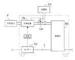
図13は、液体Lの侵入を検出するセンサーSdを用い、液体Lが侵入する際に外部電力源Pと蓄電池Bdとの間を遮断して蓄電池Bdに放電器Gdを接続するシステムの概念図である。 FIG. 13 is a conceptual diagram of a system that uses the sensor Sd that detects the intrusion of the liquid L, disconnects the external power source P and the storage battery Bd, and connects the discharger Gd to the storage battery Bd when the liquid L enters. It is.
図13に示すシステムでは、外部電力源Pと蓄電池Bdの間とを接続する充電状態と、蓄電池Bdと放電器Gdとの間を接続する放電状態とを切り替える切り替え手段SWに対して制御装置CNにより切り替え制御を行い、液体Lの侵入を検出するセンサーSdからの電気的な信号に基づき液体Lが侵入したと判断したときには、充電状態の外部電力源Pと蓄電池Bdとの間を遮断する一方、蓄電池Bdを放電器Gdに切り替える。 In the system shown in FIG. 13, the control unit CN controls the switching means SW that switches between a charging state connecting the external power source P and the storage battery Bd and a discharging state connecting the storage battery Bd and the discharger Gd. When the liquid L is determined to have entered based on the electrical signal from the sensor Sd that detects the entry of the liquid L, the switching between the external power source P and the storage battery Bd in the charged state is interrupted. The storage battery Bd is switched to the discharger Gd.
ところが、図13に示すシステムによると、充電状態の外部電力源Pと蓄電池Bdとの間を遮断して蓄電池Bdを放電器Gdに切り替えるためには、液体Lが侵入したというセンサーSdから発信された情報に基づきセンサーSdを作動させたり、制御装置CNにおける演算手段で演算処理を行って切り替え手段SWへ信号を発信したり、或いは、放電器Gdに接続する回路を動作させたりというように電気的な制御構成を用いなければならない。 However, according to the system shown in FIG. 13, in order to shut off the charged external power source P and the storage battery Bd and switch the storage battery Bd to the discharger Gd, it is transmitted from the sensor Sd that the liquid L has entered. Based on the obtained information, the sensor Sd is operated, the arithmetic means in the control device CN performs arithmetic processing to send a signal to the switching means SW, or the circuit connected to the discharger Gd is operated. A control structure must be used.
また、特許文献2に記載の二次電池では、蓄電池の正電極及び負電極にそれぞれ接続される一対の電力搬送経路の間を強制的に導通させることで、蓄電池を放電できるものの、蓄電池の正電極及び負電極への水濡れ等が発生した後に蓄電池を放電する上、放電するのに、熱収縮チューブが所定温度以上に達して収縮するまで待たなければならず、その間に、蓄電池の正電極及び負電極の端子間で水濡れ等によって漏電或いは短絡して発熱等の不都合を招き、水濡れ等の異常状態の発生時での安全性に欠ける。 Further, in the secondary battery described in
そこで、本発明は、電気的な制御構成を用いることなく、水濡れ等の異常状態の発生時での安全性を向上させることができる蓄電池の強制放電機構及び安全スイッチ装置を提供することを目的とする。 Accordingly, an object of the present invention is to provide a forced discharge mechanism and a safety switch device for a storage battery that can improve safety when an abnormal state such as water wetting occurs without using an electrical control configuration. And
本発明は、前記課題を解決するために、次の第1から第5態様の強制放電機構を提供する。
(1−1)第1態様の強制放電機構
蓄電池の正電極及び負電極にそれぞれ接続される一対の電力搬送経路の間を強制的に導通させる蓄電池の強制放電機構であって、前記電力搬送経路の間を導通させる電気抵抗体を有し、侵入した液体による浮力によって前記電気抵抗体を可動とする構成とされており、液体の比重よりも小さい相対比重のフロート部と、一方側の端子対が前記電力搬送経路のそれぞれの経路に接続されており、かつ、他方側の端子対が前記電気抵抗体に接続される放電経路と、前記電気抵抗体が設けられた前記フロート部を案内する案内部とを備えており、前記フロート部と前記案内部との間には液密構造が設けられていることを特徴とする蓄電池の強制放電機構。
(1−2)第2態様の強制放電機構
蓄電池の正電極及び負電極にそれぞれ接続される一対の電力搬送経路の間を強制的に導通させる蓄電池の強制放電機構であって、前記電力搬送経路の間を導通させる電気抵抗体を有し、侵入した液体による浮力によって前記電気抵抗体を可動とする構成とされており、液体の比重よりも小さい相対比重のフロート部と、一方側の端子対が前記電力搬送経路のそれぞれの経路に接続されており、かつ、他方側の端子対が前記電気抵抗体に接続される放電経路と、前記電気抵抗体が設けられた前記フロート部を案内する案内部とを備えており、前記案内部は、前記放電経路の他方側の端子対の前記電気抵抗体との接触部を少なくとも液密に覆うように構成されていることを特徴とする蓄電池の強制放電機構。
(1−3)第3態様の強制放電機構
蓄電池の正電極及び負電極にそれぞれ接続される一対の電力搬送経路の間を強制的に導通させる蓄電池の強制放電機構であって、前記電力搬送経路の間を導通させる電気抵抗体を有し、侵入した液体による浮力によって前記電気抵抗体を可動とする構成とされており、液体の比重よりも小さい相対比重のフロート部と、一方側の端子対が前記電力搬送経路のそれぞれの経路に接続されており、かつ、他方側の端子対が前記電気抵抗体に接続される放電経路と、前記電気抵抗体が設けられた前記フロート部を案内する案内部とを備えており、前記電気抵抗体にて発生する熱を放熱する放熱構造を備えていることを特徴とする蓄電池の強制放電機構。
(1−4)第4態様の強制放電機構
蓄電池の正電極及び負電極にそれぞれ接続される一対の電力搬送経路の間を強制的に導通させる蓄電池の強制放電機構であって、前記電力搬送経路の間を導通させる電気抵抗体を有し、侵入した液体による浮力によって前記電気抵抗体を可動とする構成とされており、液体の比重よりも小さい相対比重のフロート部と、一方側の端子対が前記電力搬送経路のそれぞれの経路に接続されており、かつ、他方側の端子対が前記電気抵抗体に接続される放電経路と、前記電気抵抗体が設けられた前記フロート部を案内する案内部とを備えており、前記電気抵抗体は、前記蓄電池に対して1000秒〜10時間の間で放電可能な抵抗値を有していることを特徴とする蓄電池の強制放電機構。
(1−5)第5態様の強制放電機構
蓄電池の正電極及び負電極にそれぞれ接続される一対の電力搬送経路の間を強制的に導通させる蓄電池の強制放電機構であって、前記電力搬送経路の間を導通させる電気抵抗体を有し、侵入した液体による浮力によって前記電気抵抗体を可動とする構成とされており、液体の比重よりも小さい相対比重のフロート部と、一方側の端子対が前記電力搬送経路のそれぞれの経路に接続されており、かつ、他方側の端子対が前記電気抵抗体に接続される放電経路と、前記電気抵抗体が設けられた前記フロート部を案内する案内部とを備えており、前記放電経路に接触される前記電気抵抗体に並列になるように前記放電経路に接続されたコンデンサーを備えていることを特徴とする蓄電池の強制放電機構。In order to solve the above problems, the present inventionprovides forced discharge mechanisms according to the following first to fifth aspects.
(1-1) Forced discharge mechanism of the first aspect A forced discharge mechanism for a storage battery that forcibly conducts between a pair of power transfer paths respectively connected to the positive electrode and the negative electrode of the storage battery, wherein the power transfer path An electric resistor that conducts between the two, and is configured to move the electric resistor by buoyancy due to the invadingliquid, a float portion having a relative specific gravity smaller than the specific gravity of the liquid, and a terminal pair on one side Are connected to the respective paths of the power transfer path and the other terminal pair is connected to the electric resistor, and the guide for guiding the float portion provided with the electric resistor. and a section, forced dischargeOrganization of the storage battery, characterized in thatthe liquid-tight structure is provided between said float unit and the guideunit.
(1-2) Forced discharge mechanism of the second aspect
A forced discharge mechanism for a storage battery that forcibly conducts between a pair of power transfer paths connected to the positive electrode and the negative electrode of the storage battery, respectively, having an electrical resistor that conducts between the power transfer paths, The electric resistor is configured to be movable by the buoyancy caused by the invading liquid, and a float portion having a relative specific gravity smaller than the specific gravity of the liquid and a terminal pair on one side are connected to the respective paths of the power transfer path. And a discharge path in which the other terminal pair is connected to the electric resistor, and a guide portion for guiding the float portion provided with the electric resistor, the guide portion comprising: A forced discharge mechanism for a storage battery, characterized in that it is configured to at least liquid-tightly cover a contact portion of the other terminal pair of the discharge path with the electrical resistor.
(1-3) Forced discharge mechanism of the third aspect
A forced discharge mechanism for a storage battery that forcibly conducts between a pair of power transfer paths connected to the positive electrode and the negative electrode of the storage battery, respectively, having an electrical resistor that conducts between the power transfer paths, The electric resistor is configured to be movable by the buoyancy caused by the invading liquid, and a float portion having a relative specific gravity smaller than the specific gravity of the liquid and a terminal pair on one side are connected to the respective paths of the power transfer path. And a discharge path in which the other terminal pair is connected to the electric resistor, and a guide portion for guiding the float portion provided with the electric resistor. A forced discharge mechanism for a storage battery, comprising a heat dissipation structure that dissipates the heat generated.
(1-4) Forced discharge mechanism of the fourth aspect
A forced discharge mechanism for a storage battery that forcibly conducts between a pair of power transfer paths connected to the positive electrode and the negative electrode of the storage battery, respectively, having an electrical resistor that conducts between the power transfer paths, The electric resistor is configured to be movable by the buoyancy caused by the invading liquid, and a float portion having a relative specific gravity smaller than the specific gravity of the liquid and a terminal pair on one side are connected to the respective paths of the power transfer path. And a discharge path in which a terminal pair on the other side is connected to the electric resistor, and a guide portion that guides the float portion provided with the electric resistor. A forcible discharge mechanism for a storage battery having a resistance value capable of discharging within 1000 seconds to 10 hours with respect to the storage battery.
(1-5) Forced discharge mechanism of the fifth aspect
A forced discharge mechanism for a storage battery that forcibly conducts between a pair of power transfer paths connected to the positive electrode and the negative electrode of the storage battery, respectively, having an electrical resistor that conducts between the power transfer paths, The electric resistor is configured to be movable by the buoyancy caused by the invading liquid, and a float portion having a relative specific gravity smaller than the specific gravity of the liquid and a terminal pair on one side are connected to the respective paths of the power transfer path. And a discharge path in which the other terminal pair is connected to the electric resistor, and a guide portion for guiding the float portion provided with the electric resistor, and is in contact with the discharge path A forced discharge mechanism for a storage battery, comprising a capacitor connected to the discharge path so as to be in parallel with the electric resistor.
本発明にいう「液体」とは、大雨、豪雨などにより冠水した水や氾濫した河川の水或いは海水などの電解液を含む概念である。 The term “liquid” as used in the present invention is a concept that includes an electrolyte such as water flooded by heavy rain, heavy rain, flooded river water, or seawater.
本発明に係る蓄電池の強制放電機構によれば、侵入した液体による浮力によって、前記電気抵抗体を可動させる。これにより、液体の侵入にあたり、可動した前記電気抵抗体によって前記電力搬送経路の間を導通させることができ、前記蓄電池を自発的に且つ自動的に放電することが可能となる。従って、液体の侵入(例えば洪水などによる水濡れ)が発生しても、前記蓄電池の正電極及び負電極の端子間で液体による漏電或いは短絡を抑制することができ、ひいては前記蓄電池の電極端子間での発熱を抑制することが可能となる。しかも、侵入した液体による浮力を利用するので、電気的な制御構成を用いることなく、前記電力搬送経路の間を導通させて前記蓄電池に蓄えられている電力量を減少させることが可能となる。さらに、液体の侵入がなくなれば前記電力搬送経路の間を元の導通していない状態に復帰(若しくは回復)させることができる。そして、前記案内部により、前記電気抵抗体が設けられた前記フロート部を案内することで、安定的に且つ確実に前記電力搬送経路の間を導通させることができる。
さらに、第1態様の強制放電機構では、前記液密構造により、前記放電経路の他方側の端子対の前記電気抵抗体との接触部への液体の侵入を効果的に防止することができる。
さらに、第2態様の強制放電機構では、前記案内部が前記接触部を少なくとも液密に覆うので、該接触部への液体の侵入を確実に防止できる。
さらに、第3態様の強制放電機構では、前記電気抵抗体の発熱による電気抵抗の上昇を抑制でき、これにより前記電気抵抗体の電気抵抗の上昇による放電性の悪化を抑制できる。
さらに、第4態様の強制放電機構では、前記電気抵抗体は、前記蓄電池の電力容量や前記電気抵抗体の発熱状態を考慮した前記抵抗値を有している。
さらに、第5の強制放電機構態様では、前記電気抵抗体が前記放電経路の他方側の端子対に接触するときに、前記電気抵抗体に過大な放電電流が流れることを回避することができる。According to the forced discharge mechanism of the storage battery according to the present invention, the electric resistor is moved by buoyancy due to the liquid that has entered. Thereby, when the liquid enters, the movable electric resistor can be connected between the power transfer paths, and the storage battery can be discharged spontaneously and automatically. Therefore, even if liquid intrusion (for example, water wet due to flooding) occurs, leakage or short circuit due to liquid can be suppressed between the positive electrode and negative electrode terminals of the storage battery, and thus between the electrode terminals of the storage battery. It is possible to suppress the heat generation at. In addition, since the buoyancy due to the invading liquid is used, it is possible to reduce the amount of power stored in the storage battery by conducting between the power transfer paths without using an electrical control configuration. Furthermore, when there is no liquid intrusion, it can be restored (or recovered) to the original non-conductive state between the power transfer paths.And by guiding the float part provided with the electric resistor by the guide part, it is possible to conduct between the power transfer paths stably and reliably.
Furthermore, in the forced discharge mechanism of the first aspect, the liquid-tight structure can effectively prevent liquid from entering the contact portion of the other terminal pair of the discharge path with the electrical resistor.
Furthermore, in the forced discharge mechanism of the second aspect, since the guide portion covers the contact portion at least in a liquid-tight manner, liquid can be reliably prevented from entering the contact portion.
Furthermore, in the forced discharge mechanism of the third aspect, it is possible to suppress an increase in electric resistance due to heat generation of the electric resistor, and thereby it is possible to suppress deterioration in discharge characteristics due to an increase in electric resistance of the electric resistor.
Furthermore, in the forced discharge mechanism of the fourth aspect, the electric resistor has the resistance value in consideration of the power capacity of the storage battery and the heat generation state of the electric resistor.
Furthermore, in the fifth forced discharge mechanism mode, it is possible to avoid an excessive discharge current from flowing through the electric resistor when the electric resistor contacts the terminal pair on the other side of the discharge path.
本発明に係る蓄電池の強制放電機構は、屋外で使用される物品に設けられることが好ましい。 The forced discharge mechanism of the storage battery according to the present invention is preferably provided in an article used outdoors.
この場合、屋外で発生しやすい液体の侵入の発生に効果的に対応させることができる。 In this case, it is possible to effectively cope with the occurrence of liquid intrusion that tends to occur outdoors.
ここで、前記フロート部の相対比重とは、前記フロート部全体としての比重の意味である。すなわち、前記フロート部は、内部が中空になっていて全体としての比重が液体の比重より小さくなっているものや、液体より真密度が小さくて液体に浮くような材料で構成されたものも含む概念である。 Here, the relative specific gravity of the float part means the specific gravity of the entire float part. In other words, the float part includes a hollow part whose overall specific gravity is smaller than the specific gravity of the liquid, and a float made of a material having a true density lower than that of the liquid and floating in the liquid. It is a concept.
本発明に係る蓄電池の強制放電機構において、前記蓄電池を覆う筐体を備えている態様を例示できる。 In the forced discharge mechanism of the storage battery according to the present invention, a mode in which a housing covering the storage battery is provided can be exemplified.
この態様では、前記筐体により、前記蓄電池を覆うので、外部からの液体の侵入を抑制することができる。 In this aspect, since the storage battery is covered by the casing, it is possible to suppress intrusion of liquid from the outside.
本発明に係る蓄電池の強制放電機構において、前記電気抵抗体を前記放電経路の他方側の端子対に接触させるときの液面が前記蓄電池の電極端子の位置よりも下方に位置するように構成されていることが好ましい。 In the forced discharge mechanism of the storage battery according to the present invention, the liquid level when the electrical resistor is brought into contact with the other terminal pair of the discharge path is configured to be positioned below the position of the electrode terminal of the storage battery. It is preferable.
この態様では、前記液面が前記蓄電池の電極端子の位置よりも下方に位置するように構成されているので、前記蓄電池の電極端子間での液体による漏電或いは短絡の前に、確実に前記電力搬送経路の間を導通させることができ、それだけ安全性を向上させることができる。 In this aspect, since the liquid level is configured to be located below the position of the electrode terminal of the storage battery, the power is surely ensured before the leakage or short circuit caused by the liquid between the electrode terminals of the storage battery. It is possible to conduct between the conveyance paths, and the safety can be improved accordingly.
本発明に係る第2から第5態様の強制放電機構において、前記フロート部と前記案内部との間には液密構造が設けられていることが好ましい。In the forced discharge mechanism accordingto the second to fifth aspects ofthe present invention, it is preferable that a liquid-tight structure is provided between the float part and the guide part.
この態様では、前記液密構造により、前記放電経路の他方側の端子対の前記電気抵抗体との接触部への液体の侵入を効果的に防止することができる。 In this aspect, the liquid-tight structure can effectively prevent liquid from entering the contact portion of the other terminal pair of the discharge path with the electrical resistor.
本発明に係る第1及び第3から第5態様の強制放電機構において、前記案内部は、前記放電経路の他方側の端子対の前記電気抵抗体との接触部を少なくとも液密に覆うように構成されていることが好ましい。In the forced discharge mechanism accordingto the first and third to fifth aspects of the present invention, the guide portion covers at least liquid-tightly the contact portion of the other terminal pair of the discharge path with the electrical resistor. It is preferable to be configured.
この態様では、前記案内部が前記接触部を少なくとも液密に覆うので、該接触部への液体の侵入を確実に防止できる。 In this aspect, since the guide part covers the contact part at least in a liquid-tight manner, the liquid can be reliably prevented from entering the contact part.
本発明に係る第1、第2、第4及び第5態様の強制放電機構において、前記電気抵抗体にて発生する熱を放熱する放熱構造を備えていることが好ましい。In the forced discharge mechanism according tothe first, second, fourth, and fifth aspects of the present invention, it is preferable to include a heat dissipation structure that dissipates heat generated by the electrical resistor.
この態様では、前記電気抵抗体の発熱による電気抵抗の上昇を抑制でき、これにより前記電気抵抗体の電気抵抗の上昇による放電性の悪化を抑制できる。 In this aspect, it is possible to suppress an increase in electrical resistance due to heat generation of the electrical resistor, and thereby it is possible to suppress a deterioration in dischargeability due to an increase in electrical resistance of the electrical resistor.
この態様の強制放電機構及び第3態様の強制放電機構において、前記放熱構造は、前記電気抵抗体にて発生する熱を当該強制放電機構の表面全体から放熱する態様を例示できる。In the forced discharge mechanism of this aspect and the forced discharge mechanism of the third aspect , the heat dissipation structure can exemplify an aspect in which heat generated in the electrical resistor is dissipated from the entire surface of the forced discharge mechanism.
この態様では、前記電気抵抗体の発熱による電気抵抗の上昇をさらに抑制でき、それだけ放電効果を向上させることができる。 In this aspect, it is possible to further suppress an increase in electrical resistance due to heat generation of the electrical resistor, and to improve the discharge effect accordingly.
本発明に係る第1から第3及び第5態様の強制放電機構において、前記蓄電池に対する放電は、速やかに行われることが好ましいが、前記蓄電池の電力容量や前記電気抵抗体の発熱状態を考慮すると、前記電気抵抗体は、例えば、前記蓄電池に対して1000秒〜10時間の間で放電可能な抵抗値を有していることが好ましい。In the forced discharge mechanisms of the first to third and fifth aspects according to the present invention, it is preferable that the discharge to the storage battery is performed quickly, but considering the power capacity of the storage battery and the heat generation state of the electric resistor. For example, the electrical resistor preferably has a resistance value that can be discharged with respect to the storage battery in 1000 seconds to 10 hours.
本発明に係る第1から第4態様の強制放電機構において、前記放電経路に接触される前記電気抵抗体に並列になるように前記放電経路に接続されたコンデンサーを備えていることが好ましい。In the forced discharge mechanism ofthe first to fourth aspects according to the present invention, it is preferable that a capacitor connected to the discharge path so as to be in parallel with the electric resistor in contact with the discharge path is provided.
この態様では、前記電気抵抗体が前記放電経路の他方側の端子対に接触するときに、前記電気抵抗体に過大な放電電流が流れることを回避することができる。 In this aspect, it is possible to avoid an excessive discharge current from flowing through the electric resistor when the electric resistor contacts the terminal pair on the other side of the discharge path.
前記コンデンサーとしては、前記電気抵抗体への過大電流を回避することができれば、何れの定格のものでもよいが、例えば、耐圧100V以上かつ静電容量10pF〜1000pFのうちの何れかの定格を有するものが好ましい。 The capacitor may have any rating as long as an excessive current to the electric resistor can be avoided. For example, the capacitor has a withstand voltage of 100 V or more and a capacitance of 10 pF to 1000 pF. Those are preferred.
ところで、本発明に係る蓄電池の強制放電機構では、例えば、前記蓄電池に電力を供給する外部電力源が前記電力搬送路を介して前記蓄電池に接続される場合、液体の侵入による前記電力搬送経路の間の導通に伴って前記外部電力源の電極間が導通してしまう。 By the way, in the forced discharge mechanism of the storage battery according to the present invention, for example, when an external power source that supplies power to the storage battery is connected to the storage battery via the power transfer path, As a result, the electrodes of the external power source become conductive.
そこで、本発明は、次の第1から第5態様の安全スイッチ装置も提供する。
(2−1)第1態様の安全スイッチ装置
蓄電池の正電極及び負電極にそれぞれ接続される一対の電力搬送経路の間を強制的に導通させる蓄電池の強制放電機構を備え、前記強制放電機構は、前記電力搬送経路の間を導通させる電気抵抗体を有し、侵入した液体による浮力によって前記電気抵抗体を可動とする構成とされており、外部電力源と前記蓄電池との間に接続される前記電力搬送経路を遮断する安全スイッチ装置であって、前記強制放電機構によって導通される前記電力搬送経路上の導通部と前記外部電力源との間を遮断可能な遮断装置を備え、前記遮断装置は、液体の侵入に伴って、前記導通部と前記外部電力源との間を遮断することを特徴とする安全スイッチ装置。
(2−2)第2態様の安全スイッチ装置
蓄電池の正電極及び負電極にそれぞれ接続される一対の電力搬送経路の間を強制的に導通させる蓄電池の強制放電機構を備え、前記強制放電機構は、前記電力搬送経路の間を導通させる電気抵抗体を有し、侵入した液体による浮力によって前記電気抵抗体を可動とする構成とされており、液体の比重よりも小さい相対比重のフロート部と、一方側の端子対が前記電力搬送経路のそれぞれの経路に接続されており、かつ、他方側の端子対が前記電気抵抗体に接続される放電経路と、前記電気抵抗体が設けられた前記フロート部を案内する案内部とを備え、外部電力源と前記蓄電池との間に接続される前記電力搬送経路を遮断する安全スイッチ装置であって、前記強制放電機構によって導通される前記電力搬送経路上の導通部と前記外部電力源との間を遮断可能な遮断装置を備え、前記遮断装置は、液体の侵入に伴って、前記電気抵抗体が前記放電経路の他方側の端子対を導通するに先立って、前記電力搬送経路上の前記導通部と前記外部電力源との間を遮断するように構成されていることを特徴とする安全スイッチ装置。
(2−3)第3態様の安全スイッチ装置
蓄電池の正電極及び負電極にそれぞれ接続される一対の電力搬送経路の間を強制的に導通させる蓄電池の強制放電機構を備え、前記強制放電機構は、前記電力搬送経路の間を導通させる電気抵抗体を有し、侵入した液体による浮力によって前記電気抵抗体を可動とする構成とされており、液体の比重よりも小さい相対比重のフロート部と、一方側の端子対が前記電力搬送経路のそれぞれの経路に接続されており、かつ、他方側の端子対が前記電気抵抗体に接続される放電経路と、前記電気抵抗体が設けられた前記フロート部を案内する案内部とを備え、外部電力源と前記蓄電池との間に接続される前記電力搬送経路を遮断する安全スイッチ装置であって、前記強制放電機構によって導通される前記電力搬送経路上の導通部と前記外部電力源との間を遮断可能な遮断装置を備え、前記遮断装置は、重力によってオン状態を維持し、かつ、重力に抗して押し上げられることでオフ状態となるスイッチ部を有する重力スイッチと、前記スイッチ部を押し上げるアクチュエータ部とを備え、前記スイッチ部は、前記電力搬送経路上の前記導通部と前記外部電力源との間に直列に接続されており、前記アクチュエータ部は、前記フロート部が液体の侵入に伴う浮力によって浮上するにあたって前記フロート部と連動する構成とされていることを特徴とする安全スイッチ装置。
(2−4)第4態様の安全スイッチ装置
蓄電池の正電極及び負電極にそれぞれ接続される一対の電力搬送経路の間を強制的に導通させる蓄電池の強制放電機構を備え、前記強制放電機構は、前記電力搬送経路の間を導通させる電気抵抗体を有し、侵入した液体による浮力によって前記電気抵抗体を可動とする構成とされており、液体の比重よりも小さい相対比重のフロート部と、一方側の端子対が前記電力搬送経路のそれぞれの経路に接続されており、かつ、他方側の端子対が前記電気抵抗体に接続される放電経路と、前記電気抵抗体が設けられた前記フロート部を案内する案内部とを備え、外部電力源と前記蓄電池との間に接続される前記電力搬送経路を遮断する安全スイッチ装置であって、前記強制放電機構によって導通される前記電力搬送経路上の導通部と前記外部電力源との間を遮断可能な遮断装置を備え、前記遮断装置は、前記電力搬送経路上の前記導通部と前記外部電力源との間に直列に接続された導電性の接続体を有し、液体の侵入に伴って、前記接続体が前記外部電力源と前記蓄電池との間で分断されるように構成されていることを特徴とする安全スイッチ装置。
(2−5)第5態様の安全スイッチ装置
蓄電池の正電極及び負電極にそれぞれ接続される一対の電力搬送経路の間を強制的に導通させる蓄電池の強制放電機構を備え、前記強制放電機構は、前記電力搬送経路の間を導通させる電気抵抗体を有し、侵入した液体による浮力によって前記電気抵抗体を可動とする構成とされており、液体の比重よりも小さい相対比重のフロート部と、一方側の端子対が前記電力搬送経路のそれぞれの経路に接続されており、かつ、他方側の端子対が前記電気抵抗体に接続される放電経路と、前記電気抵抗体が設けられた前記フロート部を案内する案内部とを備え、外部電力源と前記蓄電池との間に接続される前記電力搬送経路を遮断する安全スイッチ装置であって、前記強制放電機構によって導通される前記電力搬送経路上の導通部と前記外部電力源との間を遮断可能な遮断装置を備え、前記遮断装置は、前記電力搬送経路上の前記導通部と前記外部電力源との間に直列に接続された導電性の接続体を有し、液体の侵入に伴って、前記接続体が前記外部電力源と前記蓄電池との間で分断されるように構成されており、前記電気抵抗体は、発熱抵抗体とされており、前記接続体は、前記発熱抵抗体にて発生する熱によって溶断される温度ヒューズとされていることを特徴とする安全スイッチ装置。Therefore, the present inventionalso provides safety switch devices according to the following first to fifth aspects.
(2-1) Safety switch device according to the first aspect
A storage battery forced discharge mechanism that forcibly conducts between a pair of power transfer paths respectively connected to the positive electrode and the negative electrode of the storage battery, the forced discharge mechanism is an electrical resistance that conducts between the power transfer path A safety switch deviceconfigured to move the electric resistor by buoyancy caused by an intruded liquid and to cut off the power transfer path connected between an external power source and the storage battery. And a shut-off device capable of shutting off between the conduction part on the power transfer path conducted by the forced discharge mechanism and the external power source, and the shut-off device is connected to the conduction part as liquid enters. safety switchequipment, wherein the blocking between the external power sourceand.
(2-2) Safety switch device of the second aspect
A storage battery forced discharge mechanism that forcibly conducts between a pair of power transfer paths respectively connected to the positive electrode and the negative electrode of the storage battery, the forced discharge mechanism is an electrical resistance that conducts between the power transfer path The electric resistor is movable by buoyancy due to the invading liquid, and a float portion having a relative specific gravity smaller than the specific gravity of the liquid and a terminal pair on one side of each of the power transfer paths. A discharge path in which a terminal pair on the other side is connected to the electric resistor, and a guide portion for guiding the float portion provided with the electric resistor, and an external electric power A safety switch device that cuts off the power transfer path connected between a power source and the storage battery, the conduction unit on the power transfer path that is conducted by the forced discharge mechanism, and the external power source, A blocking device capable of blocking the gap, and the blocking device is configured so that the electrical resistor conducts the terminal pair on the other side of the discharge path with the intrusion of the liquid, before the electrical resistance body conducts the terminal pair on the other side of the discharge path. A safety switch device configured to cut off between a conduction portion and the external power source.
(2-3) Safety switch device according to the third aspect
A storage battery forced discharge mechanism that forcibly conducts between a pair of power transfer paths respectively connected to the positive electrode and the negative electrode of the storage battery, the forced discharge mechanism is an electrical resistance that conducts between the power transfer path The electric resistor is movable by buoyancy due to the invading liquid, and a float portion having a relative specific gravity smaller than the specific gravity of the liquid and a terminal pair on one side of each of the power transfer paths. A discharge path in which a terminal pair on the other side is connected to the electric resistor, and a guide portion for guiding the float portion provided with the electric resistor, and an external electric power A safety switch device that cuts off the power transfer path connected between a power source and the storage battery, the conduction unit on the power transfer path that is conducted by the forced discharge mechanism, and the external power source, A shut-off device capable of shutting off a gap, the shut-off device maintaining an on state by gravity and having a switch unit that is turned off by being pushed up against gravity; An actuator unit that pushes up, and the switch unit is connected in series between the conduction unit on the power transfer path and the external power source. A safety switch device, wherein the safety switch device is configured to be interlocked with the float portion when ascending due to accompanying buoyancy.
(2-4) The safety switch device of the fourth aspect
A storage battery forced discharge mechanism that forcibly conducts between a pair of power transfer paths respectively connected to the positive electrode and the negative electrode of the storage battery, the forced discharge mechanism is an electrical resistance that conducts between the power transfer path The electric resistor is movable by buoyancy due to the invading liquid, and a float portion having a relative specific gravity smaller than the specific gravity of the liquid and a terminal pair on one side of each of the power transfer paths. A discharge path in which a terminal pair on the other side is connected to the electric resistor, and a guide portion for guiding the float portion provided with the electric resistor, and an external electric power A safety switch device that cuts off the power transfer path connected between a power source and the storage battery, the conduction unit on the power transfer path that is conducted by the forced discharge mechanism, and the external power source, A blocking device capable of blocking the gap, and the blocking device includes a conductive connection body connected in series between the conduction portion on the power transfer path and the external power source, and intrusion of liquid Accordingly, the safety switch device is configured such that the connection body is divided between the external power source and the storage battery.
(2-5) Safety switch device according to fifth aspect
A storage battery forced discharge mechanism that forcibly conducts between a pair of power transfer paths respectively connected to the positive electrode and the negative electrode of the storage battery, the forced discharge mechanism is an electrical resistance that conducts between the power transfer path The electric resistor is movable by buoyancy due to the invading liquid, and a float portion having a relative specific gravity smaller than the specific gravity of the liquid and a terminal pair on one side of each of the power transfer paths. A discharge path in which a terminal pair on the other side is connected to the electric resistor, and a guide portion for guiding the float portion provided with the electric resistor, and an external electric power A safety switch device that cuts off the power transfer path connected between a power source and the storage battery, the conduction unit on the power transfer path that is conducted by the forced discharge mechanism, and the external power source, A blocking device capable of blocking the gap, and the blocking device includes a conductive connection body connected in series between the conduction portion on the power transfer path and the external power source, and intrusion of liquid Accordingly, the connection body is configured to be divided between the external power source and the storage battery, the electric resistor is a heat generation resistor, and the connection body is the heat generation body. A safety switch device characterized by being a thermal fuse that is blown by heat generated by a resistor.
本発明に係る第1態様の安全スイッチ装置によれば、液体の侵入に伴って前記電力搬送経路上の前記導通部と前記外部電力源との間を前記遮断装置により自動的に遮断することができる。これにより、前記強制放電機構による前記電力搬送経路の間の導通に伴って前記外部電力源の電極間が導通してしまうことを回避することができる。
この第1態様の安全スイッチ装置において、前記強制放電機構は、液体の比重よりも小さい相対比重のフロート部と、一方側の端子対が前記電力搬送経路のそれぞれの経路に接続されており、かつ、他方側の端子対が前記電気抵抗体に接続される放電経路と、前記電気抵抗体が設けられた前記フロート部を案内する案内部とを備えている態様を例示できる。According tothe safety switch device ofthe first aspect according to the present invention, it is possible to automatically shut off between the conduction portion on the power transfer path and the external power source by the shut-off device when liquid enters. it can. Thereby, it is possible to avoid conduction between the electrodes of the external power source due to conduction between the power transfer paths by the forced discharge mechanism.
In the safety switch device according to the first aspect, the forced discharge mechanism includes a float portion having a relative specific gravity smaller than the specific gravity of the liquid, and a terminal pair on one side connected to each of the power transfer routes, and A mode in which the other terminal pair includes a discharge path connected to the electric resistor and a guide portion that guides the float portion provided with the electric resistor can be exemplified.
この態様では、前記案内部により、前記電気抵抗体が設けられた前記フロート部を案内するので、安定的に且つ確実に前記電力搬送経路の間を導通させることができる。In this aspect, since the float portion provided with the electric resistor is guided by the guide portion, it is possible to establish a stable and reliable conduction between the power transfer paths.
本発明に係る第2態様の安全スイッチ装置によれば、前記強制放電機構による前記電力搬送経路の間の導通によって前記外部電力源の電極間が導通してしまう前に、前記電力搬送経路上の前記導通部と前記外部電力源との間を遮断することができ、これにより、前記強制放電機構による前記電力搬送経路の間の導通に伴って前記外部電力源の電極間の導通を確実に回避することができる。しかも、前記案内部により、前記電気抵抗体が設けられた前記フロート部を案内するので、安定的に且つ確実に前記電力搬送経路の間を導通させることができる。According to the safety switch device of the second aspect of the present invention, before the electrodes of the external power source are conducted by the conduction between the power delivery paths by the forced discharge mechanism, The connection between the conduction part and the external power source can be cut off, thereby reliably avoiding the conduction between the electrodes of the external power source along with the conduction between the power transfer paths by the forced discharge mechanism. can do.And since the said float part in which the said electrical resistance body was provided is guided by the said guide part, it can electrically connect between the said electric power conveyance paths stably and reliably.
本発明に係る第1及び第2態様の安全スイッチ装置において、前記遮断装置の具体的な第1態様として、前記遮断装置は、前記電力搬送経路上の前記導通部と前記外部電力源との間を接続する接続状態と、前記電力搬送経路上の前記導通部と前記外部電力源との間を遮断する遮断状態とを切り替え可能とされている態様を例示できる。Inthe safety switch device according tothe first and second aspects of thepresent invention, as a specific first aspect of the interruption device, the interruption device is provided between the conduction part on the power transfer path and the external power source. Can be switched between a connection state in which the power supply path is connected and a cut-off state in which the connection between the conduction unit on the power transfer path and the external power source is cut off.
この態様では、前記遮断装置は、前記電力搬送経路上の前記導通部と前記外部電力源との間の前記接続状態と前記遮断状態とを切り替え可能とされているので、液体が侵入したときに、前記遮断状態に切り替える一方、液体の侵入がなくなって前記強制放電機構による前記電力搬送経路の間の導通が解除されるにあたって、前記接続状態に切り替えることができ、前記遮断状態から前記接続状態へ復帰させることが可能となる。Astate like this, the shut-off device, because the are able to be switched between the disconnected state and the connected state between the conductive portion of the power carrier path with the external power source, the liquid has penetrated When switching to the cut-off state, the connection between the power transfer path by the forced discharge mechanism can be switched to the connection state when the liquid does not enter and the forced discharge mechanism is released. It is possible to return to the state.
この態様の具体的な一態様として、前記遮断装置は、電気信号によってオン状態とオフ状態とを切り替える制御スイッチと、前記制御スイッチの切り替え動作を制御する制御装置とを備え、前記制御スイッチは、前記電力搬送経路上の前記導通部と前記外部電力源との間に直列に接続されており、前記制御装置は、液体の侵入の有無を検知する検知センサーによる検知結果に基づき、液体が侵入したと判断した場合には、前記制御スイッチをオフ状態に切り替える態様を例示できる。As a specific aspect ofthis aspect, the shut-off device includes a control switch that switches between an on state and an off state by an electrical signal, and a control device that controls a switching operation of the control switch, and the control switch includes: It is connected in series between the conduction part on the power transfer path and the external power source, and the control device has intruded liquid based on a detection result by a detection sensor that detects the presence or absence of liquid intrusion. In the case where it is determined that the control switch is turned off, the mode can be exemplified.
この態様では、前記制御装置により、前記遮断状態と前記接続状態とを確実に切り替えることができる。さらに、前記電力搬送経路上の前記導通部と前記外部電力源との間の遮断タイミングを調整することができる。 In this aspect, the blocking state and the connection state can be reliably switched by the control device. Furthermore, the interruption | blocking timing between the said conduction | electrical_connection part on the said electric power conveyance path | route and the said external electric power source can be adjusted.
また、前記制御装置は、前記導通部と前記外部電力源との間の前記電力搬送経路上に設けられていることが好ましい。 Moreover, it is preferable that the said control apparatus is provided on the said electric power conveyance path | route between the said conduction | electrical_connection part and the said external electric power source.
この態様では、前記外部電力源からの電力を確実に前記制御装置に供給することができる。 In this aspect, the power from the external power source can be reliably supplied to the control device.
本発明に係る第3態様の安全スイッチ装置によれば、前記フロート部と前記放電経路と前記案内部とを備えた前記強制放電機構を利用して前記電力搬送経路上の前記導通部と前記外部電力源との間を遮断することができる。しかも、前記案内部により、前記電気抵抗体が設けられた前記フロート部を案内するので、安定的に且つ確実に前記電力搬送経路の間を導通させることができる。According to the safety switch device of the third aspect of the present invention, the conduction part on the power transfer path and the external part using the forced discharge mechanism including the float part, the discharge path, and the guide part. The power source can be disconnected.And since the said float part in which the said electrical resistance body was provided is guided by the said guide part, it can electrically connect between the said electric power conveyance paths stably and reliably.
かかる態様において、前記アクチュエータ部は、前記フロート部及び前記電気抵抗体と、前記スイッチ部との何れにも連結されていなくてもよいし、前記フロート部及び/又は前記電気抵抗体と、前記スイッチ部とのうち少なくとも一方に連結されていてもよい。 In this aspect, the actuator unit may not be connected to any of the float unit, the electrical resistor, and the switch unit, or the float unit and / or the electrical resistor, and the switch. It may be connected to at least one of the parts.
例えば、前記アクチュエータ部が、前記フロート部及び前記電気抵抗体と、前記スイッチ部との何れにも連結されていない場合、及び、前記アクチュエータ部が、前記フロート部及び/又は前記電気抵抗体と、前記スイッチ部との何れか一方に連結されている場合、液体の液面に生じる波によって前記フロート部が揺動することによる前記導通部と前記外部電力源との間の接続状態への影響を抑制することができる。また、前記アクチュエータ部が、前記フロート部及び/又は前記電気抵抗体と、前記スイッチ部との双方に連結されている場合には、前記フロート部と前記スイッチ部とを前記アクチュエータ部を介して確実に連動させることができる。 For example, when the actuator unit is not connected to any of the float unit and the electrical resistor and the switch unit, and the actuator unit is the float unit and / or the electrical resistor, When connected to any one of the switch units, the influence on the connection state between the conducting unit and the external power source due to the float unit oscillating due to a wave generated on the liquid surface. Can be suppressed. In addition, when the actuator unit is connected to both the float unit and / or the electric resistor and the switch unit, the float unit and the switch unit are securely connected via the actuator unit. Can be linked to
本発明に係る第4態様の安全スイッチ装置によれば、簡単な構成で前記電力搬送経路上の前記導通部と前記外部電力源との間を遮断することが可能となる。しかも、前記案内部により、前記電気抵抗体が設けられた前記フロート部を案内するので、安定的に且つ確実に前記電力搬送経路の間を導通させることができる。According to the safety switch device of the 4th mode concerning the present invention, it becomes possible to intercept between the above-mentioned conduction part on the above-mentioned electric power conveyance course, and the above-mentioned external electric power source by simple composition.And since the said float part in which the said electrical resistance body was provided is guided by the said guide part, it can electrically connect between the said electric power conveyance paths stably and reliably.
この第4態様の具体的な他の態様として、前記遮断装置は、前記接続体を分断するための分断部材を備えており、前記接続体は、前記分断部材により分断可能な被分断導電体とされており、前記分断部材は、前記フロート部が液体の侵入に伴う浮力によって浮上するにあたって前記被分断導電体を分断する構成とされている態様を例示できる。As another specific aspect of the fourth aspect, the breaking device includes a dividing member for dividing the connection body, and the connection body includes a divided conductor that can be divided by the dividing member; The dividing member can exemplify an aspect in which the divided conductor is divided when the float portion is lifted by buoyancy associated with liquid intrusion.
この態様では、前記フロート部と前記放電経路と前記案内部とを備えた前記強制放電機構を利用して前記電力搬送経路上の前記導通部と前記外部電力源との間を遮断することができる。 In this aspect, the forced discharge mechanism including the float part, the discharge path, and the guide part can be used to block between the conduction part on the power transfer path and the external power source. .
本発明に係る第1から第4態様の安全スイッチ装置において、前記強制放電機構は、前記電気抵抗体にて発生する熱を放熱する放熱構造を備えていることが好ましい。In the first to fourth aspects of the safety switch device according to the present invention, it is preferable that the forced discharge mechanism includes a heat dissipation structure that dissipates heat generated by the electric resistor.
この態様では、前記電気抵抗体の発熱による電気抵抗の上昇を抑制でき、これにより前記電気抵抗体の電気抵抗の上昇による放電性の悪化を抑制できる。In this aspect, it is possible to suppress an increase in electrical resistance due to heat generation of the electrical resistor, and thereby it is possible to suppress a deterioration in dischargeability due to an increase in electrical resistance of the electrical resistor.
さらに好ましくは、前記放熱構造は、前記電気抵抗体にて発生する熱を当該強制放電機構の表面全体から放熱する態様を例示できる。More preferably, the heat dissipation structure can exemplify a mode in which heat generated in the electric resistor is dissipated from the entire surface of the forced discharge mechanism.
この態様では、前記電気抵抗体の発熱による電気抵抗の上昇をさらに抑制でき、それだけ放電効果を向上させることができる。In this aspect, it is possible to further suppress an increase in electrical resistance due to heat generation of the electrical resistor, and to improve the discharge effect accordingly.
本発明に係る第5態様の安全スイッチ装置によれば、前記電気抵抗体を発熱抵抗体とし、該発熱抵抗体にて発生する熱を利用して、前記温度ヒューズにて前記電力搬送経路上の前記導通部と前記外部電力源との間を遮断することができる。しかも、前記案内部により、前記電気抵抗体が設けられた前記フロート部を案内するので、安定的に且つ確実に前記電力搬送経路の間を導通させることができる。According to the safety switch device of the fifth aspect of the present invention, the electrical resistor is a heating resistor, and heat generated in the heating resistor is used to connect the thermal fuse on the power transfer path. The connection between the conduction part and the external power source can be interrupted.And since the said float part in which the said electrical resistance body was provided is guided by the said guide part, it can electrically connect between the said electric power conveyance paths stably and reliably.
かかる態様において、前記発熱抵抗体にて発生する熱を断熱する断熱構造を備えていることが好ましい。 In such an aspect, it is preferable that a heat insulating structure for insulating heat generated in the heating resistor is provided.
この態様では、前記温度ヒューズの温度上昇効率を向上させることができ、それだけ早期に前記電力搬送経路上の前記導通部と前記外部電力源との間を遮断させることができる。 In this aspect, the temperature rise efficiency of the thermal fuse can be improved, and the connection between the conduction part on the power transfer path and the external power source can be interrupted earlier.
本発明に係る第1態様の安全スイッチ装置において、前記フロート部と、前記放電経路と、前記案内部とを備えている場合、及び、本発明に係る第2から第5態様の安全スイッチ装置において、前記強制放電機構は、前記電気抵抗体を前記放電経路の他方側の端子対に接触させるときの液面が前記蓄電池の電極端子の位置よりも下方に位置するように構成されていることが好ましい。In the safety switch device according to the first aspect of the present invention, the safety switch device according to the second to fifth aspects of the present invention includes the float portion, the discharge path, and the guide portion. The forced discharge mechanism is configured such that the liquid level when the electrical resistor is brought into contact with the other terminal pair on the discharge path is positioned below the position of the electrode terminal of the storage battery. preferable.
この態様では、前記液面が前記蓄電池の電極端子の位置よりも下方に位置するように構成されているので、前記蓄電池の電極端子間での液体による漏電或いは短絡の前に、確実に前記電力搬送経路の間を導通させることができ、それだけ安全性を向上させることができる。In this aspect, since the liquid level is configured to be located below the position of the electrode terminal of the storage battery, the power is surely ensured before the leakage or short circuit caused by the liquid between the electrode terminals of the storage battery. It is possible to conduct between the conveyance paths, and the safety can be improved accordingly.
本発明に係る第1態様の安全スイッチ装置において、前記フロート部と、前記放電経路と、前記案内部とを備えている場合、及び、本発明に係る第2から第5態様の安全スイッチ装置において、前記フロート部と前記案内部との間には液密構造が設けられていることが好ましい。In the safety switch device according to the first aspect of the present invention, the safety switch device according to the second to fifth aspects of the present invention includes the float portion, the discharge path, and the guide portion. It is preferable that a liquid-tight structure is provided between the float part and the guide part.
この態様では、前記液密構造により、前記放電経路の他方側の端子対の前記電気抵抗体との接触部への液体の侵入を効果的に防止することができる。In this aspect, the liquid-tight structure can effectively prevent liquid from entering the contact portion of the other terminal pair of the discharge path with the electrical resistor.
本発明に係る第1態様の安全スイッチ装置において、前記フロート部と、前記放電経路と、前記案内部とを備えている場合、及び、本発明に係る第2から第5態様の安全スイッチ装置において、前記案内部は、前記放電経路の他方側の端子対の前記電気抵抗体との接触部を少なくとも液密に覆うように構成されていることが好ましい。In the safety switch device according to the first aspect of the present invention, the safety switch device according to the second to fifth aspects of the present invention includes the float portion, the discharge path, and the guide portion. It is preferable that the guide portion is configured to at least liquid-tightly cover a contact portion between the terminal pair on the other side of the discharge path and the electrical resistor.
この態様では、前記案内部が前記接触部を少なくとも液密に覆うので、該接触部への液体の侵入を確実に防止できる。In this aspect, since the guide part covers the contact part at least in a liquid-tight manner, the liquid can be reliably prevented from entering the contact part.
本発明に係る第1態様の安全スイッチ装置において、前記フロート部と、前記放電経路と、前記案内部とを備えている場合、及び、本発明に係る第2から第5態様の安全スイッチ装置において、前記強制放電機構は、前記放電経路に接触される前記電気抵抗体に並列になるように前記放電経路に接続されたコンデンサーを備えていることが好ましい。In the safety switch device according to the first aspect of the present invention, the safety switch device according to the second to fifth aspects of the present invention includes the float portion, the discharge path, and the guide portion. The forced discharge mechanism preferably includes a capacitor connected to the discharge path so as to be in parallel with the electric resistor in contact with the discharge path.
この態様では、前記電気抵抗体が前記放電経路の他方側の端子対に接触するときに、前記電気抵抗体に過大な放電電流が流れることを回避することができる。In this aspect, it is possible to avoid an excessive discharge current from flowing through the electric resistor when the electric resistor contacts the terminal pair on the other side of the discharge path.
前記コンデンサーとしては、前記電気抵抗体への過大電流を回避することができれば、何れの定格のものでもよいが、例えば、耐圧100V以上かつ静電容量10pF〜1000pFのうちの何れかの定格を有するものが好ましい。The capacitor may have any rating as long as an excessive current to the electric resistor can be avoided. For example, the capacitor has a withstand voltage of 100 V or more and a capacitance of 10 pF to 1000 pF. Those are preferred.
本発明に係る安全スイッチ装置において、屋外で使用される物品に設けられることが好ましい。In the safety switch device according to the present invention, the safety switch device is preferably provided on an article used outdoors.
この場合、屋外で発生しやすい液体の侵入の発生に効果的に対応させることができる。In this case, it is possible to effectively cope with the occurrence of liquid intrusion that tends to occur outdoors.
本発明に係る安全スイッチ装置において、前記蓄電池を覆う筐体を備えている態様を例示できる。In the safety switch device according to the present invention, a mode in which a housing covering the storage battery is provided can be exemplified.
この態様では、前記筐体により、前記蓄電池を覆うので、外部からの液体の侵入を抑制することができる。In this aspect, since the storage battery is covered by the casing, it is possible to suppress intrusion of liquid from the outside.
本発明に係る安全スイッチ装置において、前記蓄電池に対する放電は、速やかに行われることが好ましいが、前記蓄電池の電力容量や前記電気抵抗体の発熱状態を考慮すると、前記電気抵抗体は、例えば、前記蓄電池に対して1000秒〜10時間の間で放電可能な抵抗値を有していることが好ましい。In the safety switch device according to the present invention, the discharge to the storage battery is preferably performed quickly. However, in consideration of the power capacity of the storage battery and the heat generation state of the electrical resistor, the electrical resistor is, for example, the It is preferable that the storage battery has a resistance value capable of discharging within 1000 seconds to 10 hours.
本発明に係る安全スイッチ装置は、電力系統と連系した太陽光発電システム又は電力系統と連系した燃料電池システムに好適に用いることができる。つまり、本発明に係る安全スイッチ装置において、前記外部電力源は、電力系統と連系した太陽光発電システムの太陽電池又は電力系統と連系した燃料電池システムの燃料電池であってもよい。 The safety switch device according to the present invention can be suitably used for a photovoltaic power generation system linked to an electric power system or a fuel cell system linked to an electric power system. That is, in the safety switch device according to the present invention, the external power source may be a solar cell of a solar power generation system linked to a power system or a fuel cell of a fuel cell system linked to a power system.
また、本発明に係る安全スイッチ装置において、前記蓄電池は、電気自動車又はハイブリッド電気自動車の電源であってもよい。 In the safety switch device according to the present invention, the storage battery may be a power source of an electric vehicle or a hybrid electric vehicle.
以上説明したように、本発明に係る蓄電池の強制放電機構及び安全スイッチ装置によると、電気的な制御構成を用いることなく、水濡れ等の異常状態の発生時での安全性を向上させることが可能となる。 As described above, according to the forced discharge mechanism and the safety switch device of the storage battery according to the present invention, it is possible to improve safety when an abnormal state such as water wetting occurs without using an electrical control configuration. It becomes possible.
すなわち、本発明に係る蓄電池の強制放電機構及び安全スイッチ装置によれば、侵入した液体による浮力によって、前記電気抵抗体を可動させるので、液体の侵入にあたり、可動した前記電気抵抗体によって前記電力搬送経路の間を導通させることができ、前記蓄電池を自発的に且つ自動的に放電することが可能となる。従って、液体の侵入(例えば洪水などによる水濡れ)が発生しても、前記蓄電池の正電極及び負電極の端子間で液体による漏電或いは短絡を抑制することができ、ひいては前記蓄電池の電極端子間での発熱を抑制することが可能となる。しかも、侵入した液体による浮力を利用するので、電気的な制御構成を用いることなく、前記電力搬送経路の間を導通させて前記蓄電池に蓄えられている電力量を減少させることが可能となる。さらに、液体の侵入がなくなれば前記電力搬送経路の間を元の導通していない状態に復帰(若しくは回復)させることができる。 That is, according to the forced discharge mechanism of the storage battery and the safety switch device according to the present invention, the electric resistor is moved by buoyancy due to the invading liquid, so that the electric power is conveyed by the moved electric resistor when the liquid enters. It is possible to conduct between the paths, and the storage battery can be discharged spontaneously and automatically. Therefore, even if liquid intrusion (for example, water wet due to flooding) occurs, leakage or short circuit due to liquid can be suppressed between the positive electrode and negative electrode terminals of the storage battery, and thus between the electrode terminals of the storage battery. It is possible to suppress the heat generation at. In addition, since the buoyancy due to the invading liquid is used, it is possible to reduce the amount of power stored in the storage battery by conducting between the power transfer paths without using an electrical control configuration. Furthermore, when there is no liquid intrusion, it can be restored (or recovered) to the original non-conductive state between the power transfer paths.
また、本発明に係る安全スイッチ装置によれば、液体の侵入に伴って前記電力搬送経路上の前記導通部と前記外部電力源との間を前記遮断装置により自動的に遮断することができる。これにより、前記強制放電機構による前記電力搬送経路の間の導通に伴って前記外部電力源の電極間が導通してしまうことを回避することができる。 In addition, according to the safety switch device of the present invention, it is possible to automatically shut off between the conduction part on the power transfer path and the external power source with the intrusion of liquid. Thereby, it is possible to avoid conduction between the electrodes of the external power source due to conduction between the power transfer paths by the forced discharge mechanism.
以下、本発明に係る実施の形態について図面を参照しながら説明する。なお、以下の実施の形態は、本発明を具体化した例であって、本発明の技術的範囲を限定する性格のものではない。 Embodiments according to the present invention will be described below with reference to the drawings. The following embodiments are examples embodying the present invention, and are not of a nature that limits the technical scope of the present invention.
(第1実施形態)
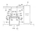
図1は、本発明の第1実施形態に係る蓄電池Bの強制放電機構100を発電システム1aに適用した一例を示す図である。(First embodiment)
FIG. 1 is a diagram showing an example in which the forced
図1に示す発電システム1aは、電力発生部10aからの直流電力を電力変換装置(ここではインバータ)20にて交流電力に変換して得られた交流電力を電力系統10bに供給し、かつ、電力系統10bと系統連系するものとされている。また、発電システム1aは、電力発生部10aからの直流電力を蓄電池Bに供給するようにもなっている。なお、電力発生部10a、電力系統10b及び電力変換装置20は、外部電力源Pとして作用する。 The
電力発生部10aは、太陽光等の自然エネルギーを直接的に電力に変換する太陽電池といった電力機器であってもよいし、燃料を供給し続けることで継続的に電力を取り出すことができる燃料電池といった電力機器であってもよい。蓄電池Bは、ここでは、複数の電池セルを含むバッテリーユニットとされている。 The
電力系統10bと連系する発電システム1aは、例えば、電力発生部10aが太陽電池である場合、自律度向上型太陽光発電システムとされ、電力発生部10aが燃料電池である場合、燃料電池システムとされる。 For example, when the
発電システム1aは、電力発生部(ここでは太陽電池又は燃料電池)10aと、電力発生部10aからの直流電力を交流電力に変換する電力変換装置20と、保護機能を有する電池モジュール30と、発電システム1a全体を制御する制御装置40とを備えており、屋外で使用されるものとされている。 The
電力変換装置20は、電力発生部10aと電力系統10bとの間に設けられており、直流電力を所定周波数の交流電力に変換する系統連系インバータとされている。電力変換装置20は、制御装置40に接続されている。制御装置40は、一対の電力搬送経路31,32を介して蓄電池Bに接続されている。 The
発電システム1aは、電力系統10bと連系し、制御装置40の指示の下、電力変換装置20を制御して、昼間などの発電量が多いときに電力発生部10aで発電した電力を蓄電池Bに蓄えるようになっている。 The
そして、蓄電池Bの強制放電機構100が電池モジュール30に備えられている。なお、電池モジュール30は、電気自動車又はハイブリッド電気自動車の電源として用いられてもよい。 The
制御装置40は、CPU(Central Processing Unit)等の処理部(図示せず)と、記憶部(図示せず)とを備えている。記憶部は、ROM(Read Only Memory)やRAM(Random Access Memory)等の記憶メモリを含み、各種制御プログラムや必要な関数およびテーブル等のデータを記憶するようになっている。発電システム1aは、制御装置40の処理部が記憶部のROMに予め格納された制御プログラムを記憶部のRAM上にロードして実行することにより、各種構成要素を制御するようになっている。 The
強制放電機構100は、蓄電池Bの正電極端子B1及び負電極端子B2にそれぞれ接続される一対の電力搬送経路31,32の間を強制的に導通させるようになっている。 The forced
強制放電機構100は、電力搬送経路31,32の間を導通させる電気抵抗体110を有している。 The forced
そして、強制放電機構100は、強制放電機構100の内部へ侵入した液体(以下、水という)Lによる浮力によって電気抵抗体110を可動とする構成とされている。 The forced
詳しくは、強制放電機構100は、例えば、河川の氾濫や洪水、高潮といった水に係わる異常時を想定して、水Lの侵入に伴って電気抵抗体110を電力搬送経路31,32からの端子対131b,132bに接触させて電力搬送経路31,32の間を導通させる。 Specifically, the forced
具体的には、強制放電機構100は、水Lによる浮力を受けるフロート部101と、電力搬送経路31,32の間を導通させるための放電経路131,132と、フロート部101を案内する案内部140とを備えている。 Specifically, the forced
フロート部101は、水Lの比重よりも小さい相対比重のものであり、ここでは、内部に空気の入った中空の密閉部材とされている。フロート部101の材質は、ここでは、電気絶縁材料とされている。 The
電気抵抗体110は、少なくとも上部に通電部が露出された電気抵抗を有する部材であり、フロート部101の上部に設けられている。電気抵抗体110は、フロート部101に複数個配置されていてもよい。 The
放電経路131,132は、一方側の端子対131a,132aが電力搬送経路31,32のそれぞれの経路に接続されており、他方側の端子対131b,132bが下方に配置されたフロート部101の上部における電気抵抗体110に臨んでいる。 In the
案内部140は、電気抵抗体110が設けられたフロート部101を案内するものである。 The
詳しくは、案内部140は、水Lの侵入に伴う浮力によって浮上するフロート部101をフロート部101に設けられた電気抵抗体110が放電経路131,132の他方側の端子対131b,132bに接触して該端子対131b,132bを導通させるように案内する構成とされている。 Specifically, in the
具体的には、案内部140は、フロート部101を上下方向に摺動自在に支持する有底筒状又は箱型の部材とされており、底板141に水Lが侵入し得る通水口141aを有している。 Specifically, the
また、強制放電機構100は、蓄電池Bを覆う筐体150を備えている。案内部140における通水口141aへの水Lの侵入を抑制し、風雨による水濡れ及び水の浸入を避けるため、ここでは、筐体150は、強制放電機構100全体を覆う電池モジュール30の外装カバーとされている。筐体150は、底部151に水Lが侵入し得る開口部151aを有している。 The forced
そして、強制放電機構100は、電気抵抗体110を放電経路131,132の他方側の端子対131b,132bに接触させるときの水面(後述する図2から図4の鎖線LL参照)が蓄電池Bの電極端子B1,B2の位置よりも下方に位置するように構成されている。 In the forced
ここでは、案内部140における通水口141aは、電池モジュール30内に設置された蓄電池Bの下端位置Baより下方に配置されている。 Here, the
以上説明した第1実施形態の蓄電池Bの強制放電機構100では、例えば、河川の氾濫や洪水、高潮といった水に係わる異常時に、電池モジュール10の筐体150に開口部151aを有しており、また、案内部140に通水口141aを有しているため、開口部151aから通水口141aを経て侵入した水Lにより、フロート部101が浮上し、フロート部101の上部に配置した電気抵抗体110が、蓄電池Bと制御装置40との間の電力搬送経路31,32を短絡させる形で電気的に連結されることによって、蓄電池Bを放電する。 The forced
詳しくは、電池モジュール30の内部に侵入した水Lによって、筐体150の内側におけるフロート部101が浮上し、フロート部101の上部に配置した電気抵抗体110が蓄電池Bからの放電経路131,132の他方側の端子対131b,132bと繋がる形で電気的に接触し、電力搬送経路31,32の間を通電させて蓄電池Bに蓄電されている電力量(電気エネルギー)を減少させる。 Specifically, the
ところで、放電経路131,132の電気抵抗体110との接触部131c,132cに水Lが接触してしまうと、例えば、水Lの電気分解が生じた場合、接触部131c,132cが存在する空間Qの内圧が上昇し、フロート部101の浮上作用が抑制され、強制放電動作を行いにくくなる上、強制放電動作が行われたとしても放電が中断してしまう恐れがある。 By the way, when the water L comes into contact with the
かかる観点から、フロート部101と案内部140との間には液密構造160が設けられている。ここでは、液密構造160は、フロート部101と案内部140の間の隙間部分(摺動部)をシリコン樹脂等の絶縁シール材161にて水密シールする構造とされている。 From this point of view, a liquid-
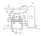
図2は、フロート部101と案内部140との間に設けられる液密構造160の他の例を説明するための概略説明図である。 FIG. 2 is a schematic explanatory diagram for explaining another example of the liquid-
図2に示すように、液密構造160は、絶縁シール材161に代えて、水Lの侵入によるフロート部101の浮上を許容するようにフロート部101と案内部140との間に設けられた第1フレキシブルフィルム162にて水密シールする構造とされていてもよい。 As shown in FIG. 2, the liquid-
また、図1に示すように、液密構造160に代えて、或いは/さらに、液密構造160に加えて(ここでは液密構造160に加えて)、案内部140は、放電経路131,132の他方側の端子対131b,132bの電気抵抗体110との接触部131c,132cを少なくとも液密に覆うように構成されている。ここでは、案内部140における放電経路131,132を導入する導入部分142,143と放電経路131,132との隙間部分を水密栓163にて水密シールする構造とされている。 Further, as shown in FIG. 1, instead of the liquid-
図3は、放電経路131,132の電気抵抗体110との接触部131c,132cを少なくとも液密に覆う他の例を説明するための概略説明図である。図3(a)は、他の例である第2フレキシブルフィルム164が絶縁シール材161と共に設けられている状態を示しており、図3(b)は、他の例である第2フレキシブルフィルム164が第1フレキシブルフィルム162と共に設けられている状態を示している。 FIG. 3 is a schematic explanatory diagram for explaining another example in which the
図3に示すように、案内部140には、水Lの侵入によるフロート部101の浮上を許容するように案内部140における通水口141aを覆う第2フレキシブルフィルム164が設けられていてもよい。 As shown in FIG. 3, the
また、強制放電機構100は、電気抵抗体110にて発生する熱を放熱する放熱構造を備えていてもよい。 The forced
フロート部101は、電気抵抗体110の温度が高くなり、電気抵抗体110の電気抵抗値が変化するのを防ぐため、電気絶縁体でありながら、フロート部101への熱の伝達を促進するような、熱伝導性の優れた材料から選ばれたもので構成することができる。また、フロート部101に対して、少なくとも電気抵抗体110と接触する部分を含む外周面を熱伝導性の優れた放熱部材で覆ってもよい。 In order to prevent the temperature of the
図4は、放熱部材102で覆ったフロート部101の一例を説明するための概略説明図である。なお、図4では、第1フレキシブルフィルム162が設けられている状態を示している。 FIG. 4 is a schematic explanatory diagram for explaining an example of the
熱伝導性の優れた材料で形成された放熱部材102は、図4に示すように、電気抵抗体110と接触する部分を覆うようにフロート部本体103に被せられている。フロート部101は放熱部材102とフロート部本体103とで構成されている。 As shown in FIG. 4, the
熱伝導性の優れた材料としては、カーボランダムや窒化ホウ素、ダイヤモンドといった無機化合物を用いてもよいが、浮力構造を考慮した成形性や加工性の点からは、熱伝導性樹脂を好適に用いることができる。熱伝導性樹脂の好適な材料として、例えば、出光興産株式会社の高熱伝導性樹脂G146Z1やT121J1を挙げることができる。 As a material having excellent thermal conductivity, an inorganic compound such as carborundum, boron nitride, or diamond may be used. However, from the viewpoint of formability and workability considering a buoyancy structure, a thermal conductive resin is preferably used. be able to. As a suitable material of heat conductive resin, high heat conductive resin G146Z1 and T121J1 of Idemitsu Kosan Co., Ltd. can be mentioned, for example.
また、強制放電機構100は、電気抵抗体110にて発生する熱を筐体150の表面全体から放熱することが好ましい。 Moreover, it is preferable that the forced
例えば、フロート部101を内包した案内部140を放熱性が優れた放熱構造にすることが好ましい。より具体的には、案内部140に対して、例えば、パーソナルコンピュータなどのコンピュータに採用されているCPUの放熱フィンのような形状を外部に施した放熱構造にすることができる。 For example, it is preferable that the
電気抵抗体110は、ここでは、蓄電池Bに対して1000秒〜10時間の間で放電可能な抵抗値のものとされている。なお、電気抵抗体110の抵抗値をR、蓄電池Bの電圧をV、電気抵抗体110に流れる電流をI、蓄電池Bに蓄えられ得る電力量をE、放電時間をTとすると、抵抗値Rは、R=(V2×T)/E、或いは、R=E/(I2×T)の式で求めることができる。Here, the
また、図1に示すように、強制放電機構100は、電気抵抗体110の放電経路131,132の他方側の端子対131b,132bへの接触時に、接触部131c,132cでの過電流を抑制するために、過電流防止用のコンデンサー170を備えていてもよい。このコンデンサー170は、放電経路131,132に接触される電気抵抗体110に並列になるように放電経路131,132に接続することができる(図1中破線参照)。コンデンサー170は、例えば、耐圧100V以上かつ静電容量10pF〜1000pFのうちの何れかの定格を有するものとされる。 Further, as shown in FIG. 1, the forced
第1実施形態によれば、侵入した水Lによる浮力によって、電気抵抗体110を可動させるので、水Lの侵入にあたり、可動した電気抵抗体110によって電力搬送経路31,32の間を導通させることができ、蓄電池Bを自発的に且つ自動的に放電することが可能となる。従って、水Lの侵入(例えば洪水などによる水濡れ)が発生しても、蓄電池Bの正電極端子及び負電極端子の端子B1,B2間で水Lによる漏電或いは短絡を抑制することができ、ひいては蓄電池Bの電極端子B1,B2間での発熱を抑制することが可能となる。しかも、侵入した水Lによる浮力を利用するので、電気的な制御構成を用いることなく、電力搬送経路31,32の間を通電させて蓄電池Bに蓄えられている電力量(電気エネルギー)を減少させることが可能となる。さらに、水Lの侵入がなくなれば電力搬送経路31,32の間を元の非導通状態に復帰(若しくは回復)させることができる。 According to the first embodiment, the
また、強制放電機構100は、屋外で発生しやすい水Lの内部への侵入の発生に効果的に対応させることができる。 Further, the forced
また、案内部140により、水Lの侵入に伴う浮力によって浮上するフロート部101をフロート部101に設けられた電気抵抗体110が放電経路131,132の他方側の端子対131b,132bに接触して他方側の端子対131b,132bを導通させるように案内するので、安定的に且つ確実に電力搬送経路31,32の間を導通させることができる。 In addition, the
また、筐体150により、蓄電池Bを覆うので、外部からの水Lの侵入を抑制することができる。 Moreover, since the storage battery B is covered with the housing | casing 150, the penetration | invasion of the water L from the outside can be suppressed.
また、強制放電機構100は、電気抵抗体110を放電経路131,132に接触させるときの水面LLが蓄電池Bの電極端子B1,B2の位置よりも下方に位置するように構成されているので、蓄電池Bの電極端子B1,B2間での水Lによる漏電或いは短絡の前に、確実に電力搬送経路31,32の間を導通させることができ、それだけ安全性を向上させることができる。 Further, the forced
また、液密構造160により、放電経路131,132の電気抵抗体121との接触部131c,132cへの水Lの侵入を効果的に防止することができる。 Further, the liquid-
また、案内部140が放電経路131,132の電気抵抗体121との接触部131c,132cを少なくとも液密に覆うので、接触部131c,132cへの水Lの侵入を確実に防止できる。 Moreover, since the
また、フロート部101が熱伝導性の優れた材料から選ばれたもので構成される場合、及び/又は、フロート部101が放熱部材102で覆われる場合、フロート部101を介して電気抵抗体110からの熱を侵入してきた水Lに伝達しやすくすることができる。これにより、電気抵抗体110の発熱による電気抵抗の上昇を抑制することができ、ひいては電気抵抗体110の電気抵抗の上昇による放電性の悪化を抑制することができる。また、電気抵抗体110にて発生する熱を筐体150の表面全体から放熱する場合には、電気抵抗体110の発熱による電気抵抗の上昇をさらに抑制でき、それだけ放電効果を向上させることができる。 Further, when the
また、コンデンサー170が放電経路131,132に接触される電気抵抗体110に並列になるように放電経路131,132に接続されている場合には、例えば、電気抵抗体110が放電経路131,132の他方側の端子対131b,132bと接触するとき、電気抵抗体110に流れはじめる放電電流が過大になることによる電気抵抗体110と端子対131b,132bとの間での火花の発生やその影響で電気抵抗体110と端子対131b,132bとが溶着するといった事態を回避することが可能である。 When the
ところで、第1実施形態では、蓄電池Bが放電している状態であれば、蓄電池Bが蓄電している電力量(電気エネルギー)を減少させるように動作するが、電力発生部10aや電力系統10bに接続されている電極端子P1,P2の間が導通してしまうことになる。このとき、蓄電池Bへの充電動作により、電力発生部10aや電力系統10bからの電力が蓄電池Bに供給されないようにすることが望ましい。 By the way, in 1st Embodiment, if the storage battery B is in the discharged state, it operates to reduce the amount of electric power (electric energy) stored in the storage battery B, but the
そこで、次の第2から第7実施形態の安全スイッチ装置200a〜200fを発電システム1b〜1gに適用することができる。 Therefore, the
(第2実施形態)
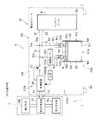
図5は、本発明の第2実施形態に係る安全スイッチ装置200aを発電システム1bに適用した一例を示す図である。(Second Embodiment)
FIG. 5 is a diagram showing an example in which the
図5に示す発電システム1bは、図1に示す発電システム1aにおいて、安全スイッチ装置200aを備えたものである。 A
図5に示す第2実施形態の発電システム1bにおいて、図1に示す第1実施形態の発電システム1aと同じ構成要素には同一符号を付し、その説明を省略する。このことは、後述する図7から図11の第3から第7実施形態についても同様である。 In the
安全スイッチ装置200aは、強制放電機構100によって導通される電力搬送経路31,32上の導通部(放電経路131,132との分岐点)31a,32aと外部電力源Pとの間を遮断可能な遮断装置210aを備えている。 The
遮断装置210aは、水Lの侵入に伴って、電力搬送経路31,32上の導通部31a,32aと外部電力源Pとの間を遮断するようになっている。 As the water L enters, the shut-off
詳しくは、遮断装置210aは、電力搬送経路31,32上の導通部31a,32aと外部電力源Pとの間を接続する接続状態と、電力搬送経路31,32上の導通部31a,32aと外部電力源Pとの間を遮断する遮断状態とを切り替え可能とされている。 Specifically, the interrupting
具体的には、遮断装置210aは、電気信号によってオン状態とオフ状態とを選択的に切り替える制御スイッチ211と、制御スイッチ211の切り替え動作を制御する制御装置40とを備えている。なお、ここでは、発電システム1bにおける制御装置40は、安全スイッチ装置200aを構成する制御装置を兼ねている。 Specifically, the
制御スイッチ211は、電力搬送経路31,32上の導通部31a,32aと外部電力源Pとの間(ここでは導通部31aと制御装置40との間の電力搬送経路31)に直列に接続されている。なお、制御スイッチ211は、電力搬送経路32に、或いは、電力搬送経路31,32の双方に直列に接続されていてもよい。 The
そして、制御装置40は、水Lの侵入の有無を検知する検知センサー50による検知結果に基づき、水Lが侵入したと判断した場合には、制御スイッチ211をオフ状態に切り替えるように構成されている。 And the
検知センサー50は、安全スイッチ装置200aの内部に設けられていてもよいし、安全スイッチ装置200aの外部に設けられていてもよい。検知センサー50は、ここでは、筐体150の内側の下端部に設けられている。検知センサー50は、制御装置40の入力系に接続されている。遮断装置210aは、検知センサー50を備えていてもよい。 The
検知センサー50は、水Lといった液体の侵入の有無を検知できるものであれば、何れものもでもよいが、検知センサー50として、侵入してきた液体を直接的に検知するという観点から、例えば、侵入してきた液体の有無を検出する液体検知センサーを挙げることができる。この場合、液体が侵入してきたことを液体検知センサーにて検知したときに、電力搬送経路31,32上の導通部31a,32aと外部電力源Pとの間を遮断させることができる。 The
検知センサー50は、ここでは、侵入してきた水Lの有無を検出する水検知センサー50aとされている。水検知センサー50aとしては、代表的には、センサー内に入った水を電気的に検知する水濡れセンサーや、フロート内で浮上するフロートスイッチが作動して水の水位を検知するフロート式の水位センサーを挙げることができる。このうち水濡れセンサーは、例えば、次のように動作する。 Here, the
図6は、水濡れセンサーによる水検出の動作を説明するための模式図である。図6に示すように、水濡れセンサーは、電気導電層C1と電気導電層C2との間に隙間Dを有しており、この隙間Dに水が侵入すると、電気導電層C1と電気導電層C2とが電気的につながった状態になる。これにより、水濡れを検知することができる。 FIG. 6 is a schematic diagram for explaining the operation of water detection by the water wetness sensor. As shown in FIG. 6, the water wetting sensor has a gap D between the electric conductive layer C1 and the electric conductive layer C2, and when water enters the gap D, the electric conductive layer C1 and the electric conductive layer C2 is electrically connected. Thereby, it is possible to detect water wetting.
第2実施形態の安全スイッチ装置200aでは、遮断装置210aにおいて、筐体150内に設けられた水検知センサー50aにより、水Lの侵入を検知して、制御装置40に信号を送り、制御装置40により、制御スイッチ211をオフ状態に切り替える。 In the
また、強制放電機構100において、フロート部101が浮上し、フロート部101の上部に設けられた電気抵抗体110が、放電経路131,132の端子対131b,132bを電気的に繋がる形で接触することで電気抵抗体110に電流が流れる。 Moreover, in the forced
ここで、電気抵抗体110が放電経路131,132の他方側の端子対131b,132bを導通する前に、水検知センサー50aによって水Lの侵入を検知するように水検知センサー50aを配置しておけば、電気抵抗体110が放電経路131,132を導通するに先立って、電力搬送経路31,32上の導通部31a,32aと外部電力源Pとの間の接続状態を遮断状態にすることができる。 Here, before the
検知センサー50は、放電経路131,132の通電の有無を検知する通電検知センサーとしてもよい。 The
(第3実施形態)
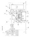
図7は、本発明の第3実施形態に係る安全スイッチ装置200bを発電システム1cに適用した一例を示す図である。(Third embodiment)
FIG. 7 is a diagram illustrating an example in which the safety switch device 200b according to the third embodiment of the present invention is applied to the
図7に示す発電システム1cは、図5に示す発電システム1bにおいて、遮断装置210aに代えて遮断装置210bを設けたものである
また、遮断装置210bは、遮断装置210aにおいて、水検知センサー50aに代えて通電検知センサー50bを設けたものである。The
通電検知センサー50bは、放電経路131,132の少なくとも一方(ここでは放電経路132)に直列に接続されており、制御装置40の入力系に接続されている。通電検知センサー50bは、ここでは電流検出器とされている。 The energization detection sensor 50 b is connected in series to at least one of the
第3実施形態の安全スイッチ装置200bでは、強制放電機構100において、フロート部101が浮上し、フロート部101の上部に設けられた電気抵抗体110が、放電経路131,132の端子対131b,132bを電気的に繋がる形で接触することで電気抵抗体110に電流が流れる。 In the safety switch device 200b of the third embodiment, in the forced
そして、遮断装置210bにおいて、通電検知センサー50bで放電経路131,132に流れる電流を検知して、制御装置40に信号を送り、第2実施形態と同様に、制御装置40により、制御スイッチ211をオフ状態に切り替える。この場合、制御装置40により、電力搬送経路31,32の間が導通したことを認識した後に、電力搬送経路31,32上の導通部31a,32aと外部電力源Pとの間を遮断させることができる。 And in the interruption | blocking
(第2及び3実施形態について)
第2及び第3実施形態によれば、水Lの侵入に伴って電力搬送経路31,32上の導通部31a,32aと外部電力源Pとの間を遮断装置210a,210bにより自動的に遮断することができる。これにより、強制放電機構100による電力搬送経路31,32の間の導通に伴って外部電力源Pの電極端子P1,P2の間が導通してしまうことを回避することができる。(About 2nd and 3rd embodiment)
According to the second and third embodiments, as the water L enters, the
また、遮断装置210a,210bは、電力搬送経路31,32上の導通部31a,32aと外部電力源Pとの間の接続状態と遮断状態とを切り替え可能とされているので、水Lが侵入したときに、遮断状態に切り替える一方、水Lの侵入がなくなって強制放電機構100による電力搬送経路31,32の間の導通が解除されるにあたって、接続状態に切り替えることができ、遮断状態から接続状態へ復帰させることが可能となる。 Moreover, since the interruption | blocking
また、制御装置40は、水Lの侵入の有無を検知する検知センサー50(水検知センサー50a,通電検知センサー50b)による検知結果に基づき、水Lが侵入したと判断した場合には、制御スイッチ211をオフ状態に切り替えるので、制御装置40により、遮断状態と接続状態とを確実に切り替えることができる。 When the
また、制御装置40は、導通部31a,32aと外部電力源Pとの間の電力搬送経路31,32上に設けられているので、外部電力源Pからの電力を確実に制御装置40に供給することができる。 Further, since the
なお、第2実施形態では、例えば、水検知センサー50aによって水Lの侵入を検知してから電気抵抗体110が放電経路131,132の他方側の端子対131b,132bを導通するまでの導通時間を予め想定して制御装置40に設定しておけば、或いは、水位検知センサー等を用いて、侵入する水Lの水位の時間的変化を検出して前記導通時間を算出すれば、電気抵抗体110と放電経路131,132との間の導通の前後において導通部31a,32aと外部電力源Pとの間の遮断タイミングを調整することができる。 In the second embodiment, for example, the conduction time from when the
また、第3実施形態では、制御装置40により、電力搬送経路31,32の間が導通したことを認識した後に、導通部31a,32aと外部電力源Pとの間を遮断させるので、電気抵抗体110と放電経路131,132との間の導通の後において導通部31a,32aと外部電力源Pとの間の遮断タイミングを調整することができる。 In the third embodiment, since the
また、第2及び第3実施形態では、水検知センサー50a及び通電検知センサー50bからの検知結果に基づき、水Lの侵入がないと判断したときからの導通部31a,32aと外部電力源Pとの間の接続タイミングを調整することができる。この場合、第3実施形態では、通電検知センサー50bを用いるので、電気抵抗体110と放電経路131,132との間の遮断後すぐに導通部31a,32aと外部電力源Pとの間を接続することができる。 Moreover, in 2nd and 3rd embodiment, it is based on the detection result from the
第2実施形態の水検知センサー50aと第3実施形態の通電検知センサー50bとを組み合わせてもよい。こうすることで、第2及び第3実施形態における互いの利点を兼ね備えることができる。すなわち、電気抵抗体110と放電経路131,132との間の導通の前後において電力搬送経路31,32上の導通部31a,32aと外部電力源Pとの間の遮断タイミングを調整することができ、しかも、電気抵抗体110と放電経路131,132との間の遮断後すぐに導通部31a,32aと外部電力源Pとの間を接続することができる。 You may combine the
(第4実施形態)
図8は、本発明の第4実施形態に係る安全スイッチ装置200cを発電システム1dに適用した一例を示す図である。(Fourth embodiment)
FIG. 8 is a diagram showing an example in which the
図8に示す発電システム1dは、図1に示す発電システム1aにおいて、安全スイッチ装置200cを備えたものである。 A
安全スイッチ装置200cは、強制放電機構100によって導通される電力搬送経路31,32上の導通部31a,32aと外部電力源Pとの間を遮断可能な遮断装置210cを備えている。 The
遮断装置210cは、水Lの侵入に伴って、導通部31a,32aと外部電力源Pとの間を遮断するようになっている。 The shut-off
詳しくは、遮断装置210cは、電力搬送経路31,32上の導通部31a,32aと外部電力源Pとの間を接続する接続状態と、電力搬送経路31,32上の導通部31a,32aと外部電力源Pとの間を遮断する遮断状態とを切り替え可能とされている。 Specifically, the
具体的には、遮断装置210cは、重力によってオン状態を維持し、かつ、重力に抗して押し上げられることでオフ状態となるスイッチ部213を有する重力スイッチ212と、スイッチ部213を押し上げるアクチュエータ部214とを備えている。 Specifically, the shut-off
スイッチ部213は、電力搬送経路31,32上の導通部31a,32aと外部電力源Pとの間(ここでは導通部32aと制御装置40との間の電力搬送経路32)に直列に接続されている。なお、スイッチ部213は、電力搬送経路31に、或いは、電力搬送経路31,32の双方に直列に接続されていてもよい。 The
重力スイッチ212は、スイッチ部213に加えて、一対のスイッチ端子213a,213bとを有している。重力スイッチ212は、案内部140の内側上方に配置されている。 The
スイッチ端子213a,213bは、導通部32aと制御装置40との間において強制放電機構100における導入部分142,143から案内部140内に引き込まれた電力搬送経路32に直列に接続されている。 The
スイッチ部213は、ここでは、棒状の導電体とされている。スイッチ部213は、スイッチ経路213a,213bの間を跨いで重力によって通電状態を維持した状態でスイッチ端子213a,213b上に載置されている。なお、スイッチ部213を放電経路131,132の他方側の端子対131b,132bに確実に接触させるという観点から、遮断装置210cは、スイッチ部213を放電経路131,132の他方側の端子対131b,132bに向けて付勢するスプリングバネ等の付勢部材(図示せず)を備えていてもよい。 Here, the
そして、アクチュエータ部214は、フロート部101が水Lの侵入に伴う浮力によって浮上するにあたってフロート部101と連動する構成とされている。 And the
具体的には、アクチュエータ部214は、柱状のものとされており、フロート部101及び/又は電気抵抗体110とスイッチ部213との間に配置されている。 Specifically, the
また、放電経路131,132の他方側の端子対131b,132bは、浮上する電気抵抗体110が端子対131b,132bに接触して電気抵抗体110のそれ以上の浮上を阻止するようになっている。 In addition, the
第4実施形態では、アクチュエータ部214は、フロート部101及び/又は電気抵抗体110と、スイッチ部213との双方に連結されている。 In the fourth embodiment, the
具体的には、アクチュエータ部214は、底部214aが電気抵抗体110の頂部110dに接合され、かつ、頂部214bがスイッチ部213の底部213dに接合されている。 Specifically, the
第4実施形態の安全スイッチ装置200cでは、内部に侵入した水Lによって、フロート部101がフロート部101及び/又は電気抵抗体110に連結されたアクチュエータ部214と共に浮上し、該浮上したアクチュエータ部214に連結されたスイッチ部213が下から押し上げられることで、重力スイッチ212がオフ状態となり、導通部31a,32aと外部電力源Pとの間の電力搬送経路31,32が一時的に遮断される。このとき、フロート部101がわずかに上昇するだけで、電力搬送経路31,32は瞬時に遮断される。 In the
一方、侵入した水Lの水位が低下すると、スイッチ部213がスイッチ端子213a,213b上に載置され、重力スイッチ212がオン状態となり、導通部31a,32aと外部電力源Pとの間の電力搬送経路31,32が再接続される。 On the other hand, when the water level of the invading water L decreases, the
(第5実施形態)
図9は、本発明の第5実施形態に係る安全スイッチ装置200dを発電システム1eに適用した一例を示す図である。(Fifth embodiment)
FIG. 9 is a diagram showing an example in which the
図9に示す発電システム1eにおける遮断装置210dは、図8に示す安全スイッチ装置200cにおける遮断装置210cにおいて、アクチュエータ部214がフロート部101及び/又は電気抵抗体110と、スイッチ部213とのうちの何れか一方(図示例ではスイッチ部213)に連結されたものである。 The shut-off
第5実施形態の安全スイッチ装置200dでは、図8の第4実施形態で示したアクチュエータ部214が、フロート部101及び/又は電気抵抗体110と、スイッチ部213とのうちの何れか一方に連結されているので、水Lの侵入がないとき(フロート部101が下方に位置しているとき)には、アクチュエータ部214とスイッチ部213とが離間しているか、或いは、アクチュエータ部214とフロート部101及び/又は電気抵抗体110とが(図示例ではアクチュエータ部214と電気抵抗体110とが)離間しており、その間に隙間Sが設けられている。この場合、フロート部101のわずかの上昇による動作が緩和され、フロート部101が上昇し始めても、導通部31a,32aと外部電力源Pとの間の電力搬送経路31,32がすぐには遮断されない。 In the
この場合も、第4実施形態と同様、侵入した水Lの水位が低下すると、スイッチ部213がスイッチ端子213a,213b上に載置され、重力スイッチ212がオン状態となり、導通部31a,32aと外部電力源Pとの間の電力搬送経路31,32が再接続される。 Also in this case, as in the fourth embodiment, when the water level of the invading water L decreases, the
なお、第5実施形態において、アクチュエータ部214は、フロート部101及び電気抵抗体110と、スイッチ部213との何れにも連結されていなくてもよい。この場合、アクチュエータ部214を上下方向移動自在に支持する支持部材(図示せず)を設けることができる。 In the fifth embodiment, the
(第4及び5実施形態について)
第4及び第5実施形態において、電気抵抗体110が放電経路131,132の他方側の端子対131b,132bに接触して端子対131b,132bが電気抵抗体110の浮上を阻止するようになっているので、アクチュエータ部214によるスイッチ部213の押し上げによって電力搬送経路31,32上の導通部31a,32aと外部電力源Pとの間を遮断させた後に、電気抵抗体110が放電経路131,132の他方側の端子対131b,132bに接触して電力搬送経路31,32の間を導通させることができる。(About 4th and 5th embodiment)
In the fourth and fifth embodiments, the
なお、電気抵抗体110が端子対131b,132bに接触しつつ電気抵抗体110の浮上を許容(端子対131b,132bと電気抵抗体110とが接触しつつ摺動)するようになっていてもよい。この場合、電気抵抗体110が端子対131b,132bに接触して電力搬送経路31,32の間を導通させた後に、アクチュエータ部214によるスイッチ部213の押し上げによって電力搬送経路31,32上の導通部32a,32bと外部電力源Pとの間を遮断させることができる。 Even if the
第4及び第5実施形態によれば、遮断装置210c,210dによって、強制放電機構100による電力搬送経路31,32の間の導通に伴って外部電力源Pの電極端子P1,P2の間が導通してしまうことを回避することができる。また、遮断装置210c,210dは、電力搬送経路31,32上の導通部31a,32aと外部電力源Pとの間において遮断状態から接続状態へ復帰させることが可能となる。しかも、強制放電機構100を利用して電力搬送経路31,32上の導通部31a,32aと外部電力源Pとの間を遮断することができる。 According to the fourth and fifth embodiments, conduction between the electrode terminals P1 and P2 of the external power source P is established by the
また、第4実施形態では、アクチュエータ部214がフロート部101及び/又は電気抵抗体110と、スイッチ部213との双方に連結されているので、フロート部101とスイッチ部213とをアクチュエータ部214を介して確実に連動させることができる。また、第5実施形態では、アクチュエータ部214がフロート部101及び/又は電気抵抗体110と、スイッチ部213との何れか一方に連結されているので、水Lの水面に生じる波によってフロート部101が揺動することによる導通部31a,32aと外部電力源Pとの間の接続状態への影響を抑制することができる。 In the fourth embodiment, since the
(第6実施形態)
図10は、本発明の第6実施形態に係る安全スイッチ装置200eを発電システム1fに適用した一例を示す図である。(Sixth embodiment)
FIG. 10 is a diagram illustrating an example in which the
図10に示す発電システム1fは、図1に示す発電システム1aにおいて、安全スイッチ装置200eを備えたものである。 A
安全スイッチ装置200eは、強制放電機構100によって導通される電力搬送経路31,32上の導通部31a,32aと外部電力源Pとの間を遮断可能な遮断装置210eを備えている。 The
遮断装置210eは、水Lの侵入に伴って、導通部31a,32aと外部電力源Pとの間を遮断するようになっている。 The shut-off
詳しくは、遮断装置210eは、電力搬送経路31,31上の導通部31a,32aと外部電力源Pとの間に直列に接続された導電性の接続体215を有し、水Lの侵入に伴って、接続体215が外部電力源Pと蓄電池Bとの間で分断されるように構成されている。 Specifically, the shut-off
具体的には、電気抵抗体110は、発熱抵抗体110aとされており、接続体215は、発熱抵抗体110aにて発生する熱によって溶断される温度ヒューズ215aとされている。 Specifically, the
温度ヒューズ215aは、電力搬送経路31,32上の導通部31a,32aと外部電力源Pとの間(ここでは導通部32aと制御装置40との間の電力搬送経路32)に直列に接続されている。なお、温度ヒューズ215aは、電力搬送経路31に、或いは、電力搬送経路31,32の双方に直列に接続されていてもよい。 The
また、温度ヒューズ215aは、導通部32aと制御装置40との間において強制放電機構100における導入部分142,143から案内部140内に引き込まれた電力搬送経路32に直列に接続されている。温度ヒューズ215aは、定格温度で溶断できるように発熱抵抗体110aの近傍に配置されている。 Further, the
第6実施形態の安全スイッチ装置200eでは、強制放電機構100において、侵入した水Lによる浮力によってフロート部101が浮上し、蓄電池Bが強制放電されて発熱抵抗体110aが発熱して、十分な雰囲気温度になったところで、温度ヒューズ215aが溶断して電力搬送経路31,32上の導通部31a,32aと外部電力源Pとの間が遮断される。ここで、外部電力源Pから電力変換装置20を介して蓄電池Bに電力が供給される場合は、発熱抵抗体110aを流れる電流量がより大きくなり、発熱量がますます大きくなる。これにより、温度ヒューズ215aを溶断するまでに要する時間を短縮でき、それだけ早期に電力搬送経路31,32上の導通部31a,32aと外部電力源Pとの間を遮断することができる。この第6実施形態では、電力搬送経路31,32の間が導通した後に、導通部31a,32aと外部電力源Pとの間が遮断される。 In the
ところで、放電経路131,132の発熱抵抗体110aとの接触部131c,132cに水Lが接触してしまうと、例えば、前述した電気分解の発生の他に、発熱抵抗体110aの発熱によって侵入した水Lが蒸発した場合、蒸発によって熱エネルギーが使われ、温度ヒューズ215aが溶断できなくなる恐れがある。しかも、蒸発によって接触部131c,132cが存在する空間Qの内圧が上昇し、フロート部101の浮上作用が抑制され、強制放電動作を行いにくくなる上、強制放電動作が行われたとしても放電が中断してしまう恐れがある。また、電気分解や蒸発により、発熱抵抗体110aの発熱が抑えられることで、温度ヒューズ215aの溶断動作も阻害される。 By the way, if the water L comes into contact with the
そこで、図1から図4に示すような液密にする構成にすることが好ましい。なお、図10の例では、図1の絶縁シール材161に代えて図2の第1フレキシブルフィルム162が設けられている。 Therefore, it is preferable to adopt a liquid-tight configuration as shown in FIGS. In the example of FIG. 10, the first
こうすることで、放電経路131,132の発熱抵抗体110aとの接触部131c,132cへの水Lの接触を防止できる。 By doing so, it is possible to prevent the water L from contacting the
また、第6実施形態では、発熱抵抗体110aからの熱の伝達方向が異なるほど、温度ヒューズ215aの応答性はよくなる。このため、発熱抵抗体110aにて発生する熱のフロート部101や筐体150への伝達を極力抑えるように、案内部材140の外側を断熱構造(断熱材で覆う構造)181とされ、或いは/さらに(ここではさらに)、フロートを内包した案内部材140(特に空間Q)の内側を断熱構造(断熱材で覆う構造)182とされている。 Further, in the sixth embodiment, the responsiveness of the
かかる断熱構造181,182の材料としては、発熱抵抗体110aにて発生する熱を断熱できれば、何れのものでもよいが、代表的には、発泡スチロールや発泡ポリウレタンといった断熱材料は勿論のこと、真空断熱パネルといった断熱材料を使用することができる。 The
第6実施形態によれば、遮断装置210eによって、強制放電機構100による電力搬送経路31,32の間の導通に伴って外部電力源Pの電極端子P1,P2の間が導通してしまうことを回避することができる。 According to the sixth embodiment, the
また、第6実施形態では、電気抵抗体110を発熱抵抗体110aとし、発熱抵抗体110aにて発生する熱を利用して、温度ヒューズ215aにて電力搬送経路31,32上の導通部31a,32aと外部電力源Pとの間を遮断することができる。 Further, in the sixth embodiment, the
また、発熱抵抗体110aにて発生する熱を断熱する断熱構造を備えているので、温度ヒューズ215aの温度上昇効率を向上させることができ、それだけ早期に導通部31a,32aと外部電力源Pとの間を遮断させることができる。 Moreover, since the heat insulation structure which insulates the heat generated in the heating resistor 110a is provided, the temperature rise efficiency of the
(第7実施形態)
図11は、本発明の第7実施形態に係る安全スイッチ装置200fを発電システム1gに適用した一例を示す図である。(Seventh embodiment)
FIG. 11 is a diagram illustrating an example in which the
図11に示す発電システム1gは、図1に示す発電システム1aにおいて、安全スイッチ装置200fを備えたものである。 A
安全スイッチ装置200fは、強制放電機構100によって導通される電力搬送経路31,32上の導通部31a,32aと外部電力源Pとの間を遮断可能な遮断装置210fを備えている。 The
遮断装置210fは、水Lの侵入に伴って、導通部31a,32aと外部電力源Pとの間を遮断するようになっている。 The shut-off
詳しくは、遮断装置210fは、電力搬送経路31,32上の導通部31a,32aと外部電力源Pとの間に直列に接続された導電性の接続体215を有し、水Lの侵入に伴って、接続体215が外部電力源Pと蓄電池Bとの間で分断されるように構成されている。 Specifically, the shut-off
具体的には、遮断装置210fは、接続体215を分断するための分断部材216を備えている。接続体215は、分断部材216により分断可能な被分断導電体215bとされている。そして、分断部材216は、フロート部101が水Lの侵入に伴う浮力によって浮上するにあたって被分断導電体215bを分断する構成とされている。 Specifically, the
被分断導電体215bは、電力搬送経路31,32上の導通部31a,32aと外部電力源Pとの間(ここでは導通部32aと制御装置40との間の電力搬送経路32)に直列に接続されている。なお、被分断導電体215bは、電力搬送経路31に、或いは、電力搬送経路31,32の双方に直列に接続されていてもよい。 The divided
また、被分断導電体215bは、導通部32aと制御装置40との間において強制放電機構100における導入部分142,143から案内部140内に引き込まれた電力搬送経路32に直列に接続されている。被分断導電体215bは、案内部材140の内側上方に配置されている。 Further, the divided
分断部材216は、フロート部101及び/又は電気抵抗体110に電気抵抗体110の上面よりの突出するように設けられている。 The dividing
また、放電経路131,132の他方側の端子対131b,132bは、浮上する電気抵抗体110が端子対131b,132bに接触して電気抵抗体110のそれ以上の浮上を阻止するようになっている。 In addition, the
分断部材216としては、被分断導電体215bへの押圧する押圧部材(例えば棒状の部材)や、被分断導電体215bを切断して分断する切断刃を例示できる。 Examples of the dividing
被分断導電体215bとしては、分断部材216で容易に分断(例えば押圧による破断或いは切断刃による切断)することが可能な材料で形成されたもの、及び/又は、分断部材216で容易に分断(例えば押圧による破断或いは切断刃による切断)することが可能な形状に形成されたものを例示できる。 The divided
分断部材216で容易に分断することが可能な材料としては、代表的には、導電性樹脂を挙げることができる。導電性樹脂で形成したものとしては、導電性樹脂シートや柔軟導線を例示できる。導電性樹脂シートや柔軟導線は、例えば、切断刃で容易に切断することができる。 A typical example of a material that can be easily divided by the dividing
被分断導電体215bが、例えば、導電性樹脂で形成されており、分断部材216が切断刃216aとされている場合には、第7実施形態の安全スイッチ装置200fでは、フロート部101の動きに合わせて、電気抵抗体110の上面から突出した切断刃216aが導電性樹脂で形成された被分断導電体215bを切断することにより、電力搬送経路31,32上の導通部31a,32aと外部電力源Pとの間が遮断される。 For example, when the parted
また、分断部材216で容易に分断することが可能な形状の加工に適した材料としては、代表的には、炭素材料を挙げることができる。また、分断部材216で容易に分断することが可能な形状としては、一方向に延びる凹状(具体的には側面視V字状)の溝形状を例示できる。 A typical example of a material suitable for processing a shape that can be easily cut by the dividing
図12は、溝部215cを有する被分断導電体215bを側面から視た模式図である。図12に示すように、被分断導電体215bには、一方向に延びる側面視V字状の溝部215cが形成されている。 FIG. 12 is a schematic view of the divided
被分断導電体215bが、例えば、図12に示すV字状の溝部215cが形成されており、分断部材216が押圧部材216bとされている場合には、第7実施形態の安全スイッチ装置200fでは、水Lの侵入に伴う浮力によって浮上したフロート部101による下からの押圧部材216bの押し上げ荷重Nがかかると、溝部215cで折れて被分断導電体215bの導通性がなくなる。 For example, when the divided
第7実施形態において、電気抵抗体110が放電経路131,132の他方側の端子対131b,132bに接触して端子対131b,132bが電気抵抗体110の浮上を阻止するようになっているので、分断部材216による被分断導電体215bの分断によって電力搬送経路31,32上の導通部31a,32aと外部電力源Pとの間を遮断させた後に、電気抵抗体110が放電経路131,132の他方側の端子対131b,132bに接触して電力搬送経路31,32の間を導通させることができる。 In the seventh embodiment, the
なお、電気抵抗体110が端子対131b,132bに接触しつつ電気抵抗体110の浮上を許容(端子対131b,132bと電気抵抗体110とが接触しつつ摺動)するようになっていてもよい。この場合、電気抵抗体110が端子対131b,132bに接触して電力搬送経路31,32の間を導通させた後に、分断部材216による被分断導電体215bの分断によって電力搬送経路31,32上の導通部31a,32aと外部電力源Pとの間を遮断させることができる。 Even if the
第7実施形態によれば、遮断装置210fによって、強制放電機構100による電力搬送経路31,32の間の導通に伴って外部電力源Pの電極端子P1,P2の間が導通してしまうことを回避することができる。しかも、強制放電機構100を利用して電力搬送経路31,32上の導通部31a,32aと外部電力源Pとの間を遮断することができる。 According to the seventh embodiment, the
(第1から第7実施形態について)
以上説明したように第1実施形態の強制放電機構100及び第2から第7実施形態の安全スイッチ装置200a〜200fでは、例えば、洪水が頻発する地域などにおいて、蓄電池Bの正電極及び負電極の端子B1,B2間で水濡れ等によって漏電或いは短絡して発熱等の不都合を防ぐことができる。さらに、第2から第7実施形態の安全スイッチ装置200a〜200fでは、強制放電機構100による電力搬送経路31,32の間の導通に伴って外部電力源Pの電極端子P1,P2の間が導通して外部電力源Pから電気抵抗体110への漏電を防ぐことできる。(About the first to seventh embodiments)
As described above, in the forced
また、第2から第5及び第7実施形態の安全スイッチ装置200a〜200d,200fの少なくとも一つを用いると、電力搬送経路31,32の間を遮断するタイミングについて強制放電開始の前にするか後にするかをも選択可能である。また、第2から第5実施形態の安全スイッチ装置200a〜200dの少なくとも一つを用いると、電力搬送経路31,32の間の遮断と放電開始の時間間隔とを調整することも可能である。 In addition, when at least one of the
また、第6実施形態の安全スイッチ装置200eでは、発熱による温度ヒューズ215aの溶断にあたって、外部電力源Pからの電力が発熱抵抗体110aにも一時的に供給されることによる発熱量の増加が、より早く温度ヒューズ215aを溶断させることに繋がるという点で有利となる。 Further, in the
なお、第1実施形態の強制放電機構100及び第2から第7実施形態の安全スイッチ装置200a〜200fは、主動力となるエンジンが発電機を兼用したハイブリット電気自動車や、電気自動車、さらには燃料電池自動車に適用されることで、例えば、道路の冠水などの災害に巻き込まれた際に、搭乗者への感電を防ぐ機構としても有効である。 Note that the forced
また、第1実施形態の強制放電機構100及び第2から第7実施形態の安全スイッチ装置200a〜200fは、機械的な動作を必要とする部分が少なく、例えば、停電時に動作させることが困難な電気回路や集積回路といった電気的制御構成を用いないため、信頼性を高めることができ、長期間動作せず、緊急時のみ動作するといった物品にも好適に用いることができる。 Further, the forced
1 太陽光発電システム又は燃料電池システム
10a 電力発生部
10b 電力系統
30 電池モジュール
31,32 電力搬送経路
31a,32a 導通部
40 制御装置
50 検知センサー
50a 水検知センサー
50b 通電検知センサー
100 強制放電機構
101 フロート部
110 電気抵抗体
110a 発熱抵抗体
131a,132a 一方側の端子対
131b,132b 他方側の端子対
131c,132c 接触部
131,132 放電経路
140 案内部
150 筐体
160 液密構造
161 絶縁シール材(液密構造の一例)
162 第1フレキシブルシール(液密構造の他の例)
163 水密栓
164 第2フレキシブルシール
181,182 断熱構造
170 コンデンサー
200a〜200f 安全スイッチ装置
210a〜210f 遮断装置
211 制御スイッチ
212 重力スイッチ
213 スイッチ部
214 アクチュエータ部
215 接続体
215a 温度ヒューズ(接続体の一例)
215b 被分断導電体(接続体の他の例)
216 分断部材
B バッテリーユニット(蓄電池の一例)
B1 正電極端子
B2 負電極端子
L 水(液体の一例)
LL 水面
P 外部電力源DESCRIPTION OF
162 First flexible seal (another example of liquid-tight structure)
163
215b Divided conductor (other example of connection body)
216 Dividing member B Battery unit (an example of a storage battery)
B1 Positive electrode terminal B2 Negative electrode terminal L Water (an example of liquid)
LL Water surface P External power source
Claims (41)
Translated fromJapanese前記電力搬送経路の間を導通させる電気抵抗体を有し、侵入した液体による浮力によって前記電気抵抗体を可動とする構成とされており、
液体の比重よりも小さい相対比重のフロート部と、一方側の端子対が前記電力搬送経路のそれぞれの経路に接続されており、かつ、他方側の端子対が前記電気抵抗体に接続される放電経路と、前記電気抵抗体が設けられた前記フロート部を案内する案内部とを備えており、
前記フロート部と前記案内部との間には液密構造が設けられていることを特徴とする蓄電池の強制放電機構。A forced discharge mechanism of a storage battery that forcibly conducts between a pair of power transfer paths respectively connected to the positive electrode and the negative electrode of the storage battery,
It has an electrical resistor that conducts between the power transfer path, and is configured to move the electrical resistor by buoyancy due to the invading liquid,
A discharge in which a float part having a relative specific gravity smaller than the specific gravity of the liquid, a terminal pair on one side is connected to each of the power transfer paths, and a terminal pair on the other side is connected to the electric resistor A path, and a guide portion for guiding the float portion provided with the electric resistor,
A forced discharge mechanism for a storage battery,wherein a liquid-tight structure is provided between the float part and the guide part .
前記電力搬送経路の間を導通させる電気抵抗体を有し、侵入した液体による浮力によって前記電気抵抗体を可動とする構成とされており、
液体の比重よりも小さい相対比重のフロート部と、一方側の端子対が前記電力搬送経路のそれぞれの経路に接続されており、かつ、他方側の端子対が前記電気抵抗体に接続される放電経路と、前記電気抵抗体が設けられた前記フロート部を案内する案内部とを備えており、
前記案内部は、前記放電経路の他方側の端子対の前記電気抵抗体との接触部を少なくとも液密に覆うように構成されていることを特徴とする蓄電池の強制放電機構。A forced discharge mechanism of a storage battery that forcibly conducts between a pair of power transfer paths respectively connected to the positive electrode and the negative electrode of the storage battery,
It has an electrical resistor that conducts between the power transfer path, and is configured to move the electrical resistor by buoyancy due to the invading liquid,
A discharge in which a float part having a relative specific gravity smaller than the specific gravity of the liquid, a terminal pair on one side is connected to each of the power transfer paths, and a terminal pair on the other side is connected to the electric resistor A path, and a guide portion for guiding the float portion provided with the electric resistor,
The forced discharge mechanism for a storage battery,wherein the guide portion is configured to at least liquid-tightly cover a contact portion of the other terminal pair of the discharge path with the electrical resistor .
前記電力搬送経路の間を導通させる電気抵抗体を有し、侵入した液体による浮力によって前記電気抵抗体を可動とする構成とされており、
液体の比重よりも小さい相対比重のフロート部と、一方側の端子対が前記電力搬送経路のそれぞれの経路に接続されており、かつ、他方側の端子対が前記電気抵抗体に接続される放電経路と、前記電気抵抗体が設けられた前記フロート部を案内する案内部とを備えており、
前記電気抵抗体にて発生する熱を放熱する放熱構造を備えていることを特徴とする蓄電池の強制放電機構。A forced discharge mechanism of a storage battery that forcibly conducts between a pair of power transfer paths respectively connected to the positive electrode and the negative electrode of the storage battery,
It has an electrical resistor that conducts between the power transfer path, and is configured to move the electrical resistor by buoyancy due to the invading liquid,
A discharge in which a float part having a relative specific gravity smaller than the specific gravity of the liquid, a terminal pair on one side is connected to each of the power transfer paths, and a terminal pair on the other side is connected to the electric resistor A path, and a guide portion for guiding the float portion provided with the electric resistor,
A forced discharge mechanism for a storage battery,comprising a heat dissipation structure that dissipates heat generated by the electrical resistor .
前記放熱構造は、前記電気抵抗体にて発生する熱を当該強制放電機構の表面全体から放熱することを特徴とする蓄電池の強制放電機構。A forced discharge mechanism for a storage battery according to claim3 ,
The said heat dissipation structure radiates the heat | fever which generate | occur | produces in the said electrical resistor from the whole surface of the said forced discharge mechanism, The forced discharge mechanism of the storage battery characterized by the above-mentioned.
前記電力搬送経路の間を導通させる電気抵抗体を有し、侵入した液体による浮力によって前記電気抵抗体を可動とする構成とされており、
液体の比重よりも小さい相対比重のフロート部と、一方側の端子対が前記電力搬送経路のそれぞれの経路に接続されており、かつ、他方側の端子対が前記電気抵抗体に接続される放電経路と、前記電気抵抗体が設けられた前記フロート部を案内する案内部とを備えており、
前記電気抵抗体は、前記蓄電池に対して1000秒〜10時間の間で放電可能な抵抗値を有していることを特徴とする蓄電池の強制放電機構。A forced discharge mechanism of a storage battery that forcibly conducts between a pair of power transfer paths respectively connected to the positive electrode and the negative electrode of the storage battery,
It has an electrical resistor that conducts between the power transfer path, and is configured to move the electrical resistor by buoyancy due to the invading liquid,
A discharge in which a float part having a relative specific gravity smaller than the specific gravity of the liquid, a terminal pair on one side is connected to each of the power transfer paths, and a terminal pair on the other side is connected to the electric resistor A path, and a guide portion for guiding the float portion provided with the electric resistor,
The said electrical resistor has the resistance value which can be discharged in 1000 second-10 hours with respect to the said storage battery, The forced discharge mechanism of the storage battery characterized by the above-mentioned.
前記電力搬送経路の間を導通させる電気抵抗体を有し、侵入した液体による浮力によって前記電気抵抗体を可動とする構成とされており、
液体の比重よりも小さい相対比重のフロート部と、一方側の端子対が前記電力搬送経路のそれぞれの経路に接続されており、かつ、他方側の端子対が前記電気抵抗体に接続される放電経路と、前記電気抵抗体が設けられた前記フロート部を案内する案内部とを備えており、
前記放電経路に接触される前記電気抵抗体に並列になるように前記放電経路に接続されたコンデンサーを備えていることを特徴とする蓄電池の強制放電機構。A forced discharge mechanism of a storage battery that forcibly conducts between a pair of power transfer paths respectively connected to the positive electrode and the negative electrode of the storage battery,
It has an electrical resistor that conducts between the power transfer path, and is configured to move the electrical resistor by buoyancy due to the invading liquid,
A discharge in which a float part having a relative specific gravity smaller than the specific gravity of the liquid, a terminal pair on one side is connected to each of the power transfer paths, and a terminal pair on the other side is connected to the electric resistor A path, and a guide portion for guiding the float portion provided with the electric resistor,
A forced discharge mechanism for a storage battery, comprising a capacitor connected to the discharge path so as to be in parallel with the electric resistor that is in contact with the discharge path .
前記コンデンサーは、耐圧100V以上かつ静電容量10pF〜1000pFのうちの何れかの定格を有するものであることを特徴とする蓄電池の強制放電機構。A forced discharge mechanism for a storage battery according to claim6 ,
The capacitor is a forced discharge mechanism for a storage battery, characterized in that the capacitor has a withstand voltage of 100 V or more and a rating of any one of an electrostatic capacity of 10 pF to 1000 pF.
屋外で使用される物品に設けられることを特徴とする蓄電池の強制放電機構。A forced discharge mechanism for a storage battery according toany one ofclaims 1 to 7 ,
A forced discharge mechanism for a storage battery, which is provided in an article used outdoors.
前記蓄電池を覆う筐体を備えていることを特徴とする蓄電池の強制放電機構。A forced discharge mechanism for a storage battery according toany one ofclaims 1 to 8 ,
A forced discharge mechanism for a storage battery, comprising a housing that covers the storage battery.
前記電気抵抗体を前記放電経路の他方側の端子対に接触させるときの液面が前記蓄電池の電極端子の位置よりも下方に位置するように構成されていることを特徴とする蓄電池の強制放電機構。A forced discharge mechanism of a storage battery accordingto claim1,any one of up to claim9,
A forced discharge of a storage battery characterized in that a liquid level when the electrical resistor is brought into contact with a terminal pair on the other side of the discharge path is positioned below a position of an electrode terminal of the storage battery. mechanism.
前記フロート部と前記案内部との間には液密構造が設けられていることを特徴とする蓄電池の強制放電機構。A forced discharge mechanism for a storage battery according to any one of claims2 to10 ,
A forced discharge mechanism for a storage battery, wherein a liquid-tight structure is provided between the float part and the guide part.
前記案内部は、前記放電経路の他方側の端子対の前記電気抵抗体との接触部を少なくとも液密に覆うように構成されていることを特徴とする蓄電池の強制放電機構。A forced discharge mechanism for a storage battery according to any one of claims1 or3 to11 ,
The forced discharge mechanism for a storage battery, wherein the guide portion is configured to at least liquid-tightly cover a contact portion of the other terminal pair of the discharge path with the electrical resistor.
前記電気抵抗体にて発生する熱を放熱する放熱構造を備えていることを特徴とする蓄電池の強制放電機構。A forced discharge mechanism for a storage battery according to any one ofclaims 1 to 2, or any one of claims5 to12 .
A forced discharge mechanism for a storage battery, comprising a heat dissipation structure that dissipates heat generated by the electrical resistor.
前記放熱構造は、前記電気抵抗体にて発生する熱を当該強制放電機構の表面全体から放熱することを特徴とする蓄電池の強制放電機構。A forced discharge mechanism for a storage battery according to claim13 ,
The said heat dissipation structure radiates the heat | fever which generate | occur | produces in the said electrical resistor from the whole surface of the said forced discharge mechanism, The forced discharge mechanism of the storage battery characterized by the above-mentioned.
前記電気抵抗体は、前記蓄電池に対して1000秒〜10時間の間で放電可能な抵抗値を有していることを特徴とする蓄電池の強制放電機構。A forced discharge mechanism for a storage battery according to any one ofclaims 1 to 4 or any one of claims6 to14 ,
The said electrical resistor has the resistance value which can be discharged in 1000 second-10 hours with respect to the said storage battery, The forced discharge mechanism of the storage battery characterized by the above-mentioned.
前記放電経路に接触される前記電気抵抗体に並列になるように前記放電経路に接続されたコンデンサーを備えていることを特徴とする蓄電池の強制放電機構。A forced discharge mechanism for a storage battery according to any one ofclaims 1 to 5 or any one of claims8 to15 ,
A forced discharge mechanism for a storage battery, comprising a capacitor connected to the discharge path so as to be in parallel with the electric resistor that is in contact with the discharge path.
前記コンデンサーは、耐圧100V以上かつ静電容量10pF〜1000pFのうちの何れかの定格を有するものであることを特徴とする蓄電池の強制放電機構。A forced discharge mechanism for a storage battery according to claim16 ,
The capacitor is a forced discharge mechanism for a storage battery, characterized in that the capacitor has a withstand voltage of 100 V or more and a rating of any one of an electrostatic capacity of 10 pF to 1000 pF.
前記強制放電機構によって導通される前記電力搬送経路上の導通部と前記外部電力源との間を遮断可能な遮断装置を備え、
前記遮断装置は、液体の侵入に伴って、前記導通部と前記外部電力源との間を遮断することを特徴とする安全スイッチ装置。A storage battery forced discharge mechanism that forcibly conducts between a pair of power transfer paths respectively connected to the positive electrode and the negative electrode of the storage battery, the forced discharge mechanism is an electrical resistance that conducts between the power transfer path A safety switch device configured to move the electric resistor by buoyancy caused by an intruded liquid and to cut off the power transfer path connected between an external power source and the storage battery. And
A disconnecting device capable of interrupting between a conduction part on the power transfer path and the external power source that are conducted by the forced discharge mechanism;
The safety device according to claim 1, wherein the shut-off device shuts off the conduction portion and the external power source when liquid enters.
前記強制放電機構は、液体の比重よりも小さい相対比重のフロート部と、一方側の端子対が前記電力搬送経路のそれぞれの経路に接続されており、かつ、他方側の端子対が前記電気抵抗体に接続される放電経路と、前記電気抵抗体が設けられた前記フロート部を案内する案内部とを備えていることを特徴とする安全スイッチ装置。The safety switch device according to claim 18 ,
The forced discharge mechanism includes a float portion having a relative specific gravity smaller than the specific gravity of the liquid, a terminal pair on one side being connected to each path of the power transfer path, and a terminal pair on the other side being the electric resistance. A safety switch device comprising: a discharge path connected to a body; and a guide portion for guiding the float portion provided with the electric resistor.
前記強制放電機構によって導通される前記電力搬送経路上の導通部と前記外部電力源との間を遮断可能な遮断装置を備え、
前記遮断装置は、液体の侵入に伴って、前記電気抵抗体が前記放電経路の他方側の端子対を導通するに先立って、前記電力搬送経路上の前記導通部と前記外部電力源との間を遮断するように構成されていることを特徴とする安全スイッチ装置。A storage battery forced discharge mechanism that forcibly conducts between a pair of power transfer paths respectively connected to the positive electrode and the negative electrode of the storage battery, the forced discharge mechanism is an electrical resistance that conducts between the power transfer path The electric resistor is movable by buoyancy due to the invading liquid, and a float portion having a relative specific gravity smaller than the specific gravity of the liquid and a terminal pair on one side of each of the power transfer paths. A discharge path in which a terminal pair on the other side is connected to the electric resistor, and a guide portion for guiding the float portion provided with the electric resistor, and an external electric power A safety switch device that cuts off the power transfer path connected between a source and the storage battery,
A disconnecting device capable of interrupting between a conduction part on the power transfer path and the external power source that are conducted by the forced discharge mechanism;
The shut-off device is provided between the conducting part on the power transfer path and the external power source before the electrical resistor conducts the terminal pair on the other side of the discharge path with liquid intrusion. A safety switch device, characterized in that it is configured to shut off.
前記遮断装置は、前記電力搬送経路上の前記導通部と前記外部電力源との間を接続する接続状態と、前記電力搬送経路上の前記導通部と前記外部電力源との間を遮断する遮断状態とを切り替え可能とされていることを特徴とする安全スイッチ装置。The safety switch device according toany one of claims18 to20 , wherein
The interrupting device is configured to connect between the conduction unit on the power transfer path and the external power source, and to shut off between the conduction unit on the power transfer path and the external power source. A safety switch device characterized in that it can be switched between states.
前記遮断装置は、電気信号によってオン状態とオフ状態とを切り替える制御スイッチと、前記制御スイッチの切り替え動作を制御する制御装置とを備え、
前記制御スイッチは、前記電力搬送経路上の前記導通部と前記外部電力源との間に直列に接続されており、
前記制御装置は、液体の侵入の有無を検知する検知センサーによる検知結果に基づき、液体が侵入したと判断した場合には、前記制御スイッチをオフ状態に切り替えることを特徴とする安全スイッチ装置。The safety switch device according to claim21 , wherein
The blocking device includes a control switch that switches between an on state and an off state by an electrical signal, and a control device that controls a switching operation of the control switch,
The control switch is connected in series between the conduction unit on the power transfer path and the external power source,
The control device switches the control switch to an off state when it is determined that liquid has entered based on a detection result of a detection sensor that detects whether or not liquid has entered.
前記制御装置は、前記導通部と前記外部電力源との間の前記電力搬送経路上に設けられていることを特徴とする安全スイッチ装置。The safety switch device according to claim22 ,
The safety switch device according to claim 1, wherein the control device is provided on the power transfer path between the conduction unit and the external power source.
前記強制放電機構によって導通される前記電力搬送経路上の導通部と前記外部電力源との間を遮断可能な遮断装置を備え、
前記遮断装置は、重力によってオン状態を維持し、かつ、重力に抗して押し上げられることでオフ状態となるスイッチ部を有する重力スイッチと、前記スイッチ部を押し上げるアクチュエータ部とを備え、
前記スイッチ部は、前記電力搬送経路上の前記導通部と前記外部電力源との間に直列に接続されており、
前記アクチュエータ部は、前記フロート部が液体の侵入に伴う浮力によって浮上するにあたって前記フロート部と連動する構成とされていることを特徴とする安全スイッチ装置。A storage battery forced discharge mechanism that forcibly conducts between a pair of power transfer paths respectively connected to the positive electrode and the negative electrode of the storage battery, the forced discharge mechanism is an electrical resistance that conducts between the power transfer path The electric resistor is movable by buoyancy due to the invading liquid, and a float portion having a relative specific gravity smaller than the specific gravity of the liquid and a terminal pair on one side of each of the power transfer paths. A discharge path in which a terminal pair on the other side is connected to the electric resistor, and a guide portion for guiding the float portion provided with the electric resistor, and an external electric power A safety switch device that cuts off the power transfer path connected between a source and the storage battery,
A disconnecting device capable of interrupting between a conduction part on the power transfer path and the external power source that are conducted by the forced discharge mechanism;
The shut-off device includes a gravity switch having a switch part that is turned off by being pushed up against gravity while maintaining the on state by gravity, and an actuator part that pushes up the switch part,
The switch unit is connected in series between the conduction unit on the power transfer path and the external power source,
The actuator unit is configured to interlock with the float unit when the float unit is lifted by buoyancy associated with liquid intrusion.
前記アクチュエータ部は、前記フロート部及び前記電気抵抗体と、前記スイッチ部との何れにも連結されていないか、或いは、前記フロート部及び/又は前記電気抵抗体と、前記スイッチ部とのうち少なくとも一方に連結されていることを特徴とする安全スイッチ装置。A safety switch device according to claim24 ,
The actuator unit is not connected to any of the float unit and the electrical resistor and the switch unit, or at least of the float unit and / or the electrical resistor and the switch unit. A safety switch device connected to one side.
前記強制放電機構によって導通される前記電力搬送経路上の導通部と前記外部電力源との間を遮断可能な遮断装置を備え、
前記遮断装置は、前記電力搬送経路上の前記導通部と前記外部電力源との間に直列に接続された導電性の接続体を有し、液体の侵入に伴って、前記接続体が前記外部電力源と前記蓄電池との間で分断されるように構成されていることを特徴とする安全スイッチ装置。A storage battery forced discharge mechanism that forcibly conducts between a pair of power transfer paths respectively connected to the positive electrode and the negative electrode of the storage battery, the forced discharge mechanism is an electrical resistance that conducts between the power transfer path The electric resistor is movable by buoyancy due to the invading liquid, and a float portion having a relative specific gravity smaller than the specific gravity of the liquid and a terminal pair on one side of each of the power transfer paths. A discharge path in which a terminal pair on the other side is connected to the electric resistor, and a guide portion for guiding the float portion provided with the electric resistor, and an external electric power A safety switch device that cuts off the power transfer path connected between a source and the storage battery,
A disconnecting device capable of interrupting between a conduction part on the power transfer path and the external power source that are conducted by the forced discharge mechanism;
The shut-off device has a conductive connection body connected in series between the conduction portion on the power transfer path and the external power source, and the connection body is connected to the external body as liquid enters. A safety switch device configured to be divided between a power source and the storage battery.
前記遮断装置は、前記接続体を分断するための分断部材を備えており、前記接続体は、前記分断部材により分断可能な被分断導電体とされており、前記分断部材は、前記フロート部が液体の侵入に伴う浮力によって浮上するにあたって前記被分断導電体を分断する構成とされていることを特徴とする安全スイッチ装置。The safety switch device according to claim26 ,
The interruption device includes a dividing member for dividing the connection body, the connection body is a conductor to be divided that can be divided by the division member, and the separation member includes the float portion. A safety switch device characterized by being configured to divide the to-be-divided conductor when levitation is caused by buoyancy associated with liquid intrusion.
前記強制放電機構は、前記電気抵抗体にて発生する熱を放熱する放熱構造を備えていることを特徴とする安全スイッチ装置。The safety switch device according to claim 1, wherein the forced discharge mechanism includes a heat dissipation structure that dissipates heat generated by the electric resistor.
前記放熱構造は、前記電気抵抗体にて発生する熱を当該強制放電機構の表面全体から放熱することを特徴とする安全スイッチ装置。The heat dissipating structure dissipates heat generated in the electric resistor from the entire surface of the forced discharge mechanism.
前記強制放電機構によって導通される前記電力搬送経路上の導通部と前記外部電力源との間を遮断可能な遮断装置を備え、
前記遮断装置は、前記電力搬送経路上の前記導通部と前記外部電力源との間に直列に接続された導電性の接続体を有し、液体の侵入に伴って、前記接続体が前記外部電力源と前記蓄電池との間で分断されるように構成されており、
前記電気抵抗体は、発熱抵抗体とされており、前記接続体は、前記発熱抵抗体にて発生する熱によって溶断される温度ヒューズとされていることを特徴とする安全スイッチ装置。A storage battery forced discharge mechanism that forcibly conducts between a pair of power transfer paths respectively connected to the positive electrode and the negative electrode of the storage battery, the forced discharge mechanism is an electrical resistance that conducts between the power transfer path The electric resistor is movable by buoyancy due to the invading liquid, and a float portion having a relative specific gravity smaller than the specific gravity of the liquid and a terminal pair on one side of each of the power transfer paths. A discharge path in which a terminal pair on the other side is connected to the electric resistor, and a guide portion for guiding the float portion provided with the electric resistor, and an external electric power A safety switch device that cuts off the power transfer path connected between a source and the storage battery,
A disconnecting device capable of interrupting between a conduction part on the power transfer path and the external power source that are conducted by the forced discharge mechanism;
The shut-off device has a conductive connection body connected in series between the conduction portion on the power transfer path and the external power source, and the connection body is connected to the external body as liquid enters. It is configured to be divided between a power source and the storage battery,
The safety switch device, wherein the electrical resistor is a heating resistor, and the connection body is a thermal fuse that is blown by heat generated in the heating resistor.
前記発熱抵抗体にて発生する熱を断熱する断熱構造を備えていることを特徴とする安全スイッチ装置。A storage battery safety switch device according to claim30 ,
A safety switch device comprising a heat insulating structure for insulating heat generated in the heating resistor.
前記強制放電機構は、前記電気抵抗体を前記放電経路の他方側の端子対に接触させるときの液面が前記蓄電池の電極端子の位置よりも下方に位置するように構成されていることを特徴とする安全スイッチ装置。The forced discharge mechanism is configured such that a liquid level when the electrical resistor is brought into contact with a terminal pair on the other side of the discharge path is positioned below a position of an electrode terminal of the storage battery. Safety switch device.
前記フロート部と前記案内部との間には液密構造が設けられていることを特徴とする安全スイッチ装置。A safety switch device, wherein a liquid-tight structure is provided between the float part and the guide part.
前記案内部は、前記放電経路の他方側の端子対の前記電気抵抗体との接触部を少なくとも液密に覆うように構成されていることを特徴とする蓄電池の安全スイッチ装置。The safety switch device for a storage battery, wherein the guide portion is configured to at least liquid-tightly cover a contact portion of the terminal pair on the other side of the discharge path with the electrical resistor.
前記強制放電機構は、前記放電経路に接触される前記電気抵抗体に並列になるように前記放電経路に接続されたコンデンサーを備えていることを特徴とする安全スイッチ装置。The said forced discharge mechanism is provided with the capacitor | condenser connected to the said discharge path so that it may be parallel to the said electrical resistor which contacts the said discharge path, The safety switch apparatus characterized by the above-mentioned.
前記コンデンサーは、耐圧100V以上かつ静電容量10pF〜1000pFのうちの何れかの定格を有するものであることを特徴とする安全スイッチ装置。The capacitor is a safety switch device having a withstand voltage of 100 V or more and a rating of any one of capacitances of 10 pF to 1000 pF.
屋外で使用される物品に設けられることを特徴とする安全スイッチ装置。A safety switch device provided on an article used outdoors.
前記蓄電池を覆う筐体を備えていることを特徴とする安全スイッチ装置。A safety switch device comprising a housing that covers the storage battery.
前記電気抵抗体は、前記蓄電池に対して1000秒〜10時間の間で放電可能な抵抗値を有していることを特徴とする安全スイッチ装置。The safety switch device, wherein the electrical resistor has a resistance value that can be discharged with respect to the storage battery in 1000 seconds to 10 hours.
前記外部電力源は、電力系統と連系した太陽光発電システムにおける太陽電池又は電力系統と連系した燃料電池システムにおける燃料電池であることを特徴とする安全スイッチ装置。The safety switch device according to any one of claims18 to39 ,
The safety switch device, wherein the external power source is a solar cell in a solar power generation system linked to a power system or a fuel cell in a fuel cell system linked to a power system.
前記蓄電池は、電気自動車又はハイブリッド電気自動車の電源であることを特徴とする安全スイッチ装置。The safety switch device according to any one of claims18 to39 ,
The storage battery is a power source for an electric vehicle or a hybrid electric vehicle.
Priority Applications (3)
| Application Number | Priority Date | Filing Date | Title |
|---|---|---|---|
| JP2009272252AJP5073733B2 (en) | 2009-11-30 | 2009-11-30 | Storage battery forced discharge mechanism and safety switch device |
| US12/956,150US20110127945A1 (en) | 2009-11-30 | 2010-11-30 | Forced discharge mechanism and safety switch device for storage battery |
| CN2010105687144ACN102082258A (en) | 2009-11-30 | 2010-11-30 | Forced discharge mechanism and safety switch device for storage battery |
Applications Claiming Priority (1)
| Application Number | Priority Date | Filing Date | Title |
|---|---|---|---|
| JP2009272252AJP5073733B2 (en) | 2009-11-30 | 2009-11-30 | Storage battery forced discharge mechanism and safety switch device |
Publications (2)
| Publication Number | Publication Date |
|---|---|
| JP2011115030A JP2011115030A (en) | 2011-06-09 |
| JP5073733B2true JP5073733B2 (en) | 2012-11-14 |
Family
ID=44068358
Family Applications (1)
| Application Number | Title | Priority Date | Filing Date |
|---|---|---|---|
| JP2009272252AExpired - Fee RelatedJP5073733B2 (en) | 2009-11-30 | 2009-11-30 | Storage battery forced discharge mechanism and safety switch device |
Country Status (3)
| Country | Link |
|---|---|
| US (1) | US20110127945A1 (en) |
| JP (1) | JP5073733B2 (en) |
| CN (1) | CN102082258A (en) |
Families Citing this family (443)
| Publication number | Priority date | Publication date | Assignee | Title |
|---|---|---|---|---|
| US20070084897A1 (en) | 2003-05-20 | 2007-04-19 | Shelton Frederick E Iv | Articulating surgical stapling instrument incorporating a two-piece e-beam firing mechanism |
| US9060770B2 (en) | 2003-05-20 | 2015-06-23 | Ethicon Endo-Surgery, Inc. | Robotically-driven surgical instrument with E-beam driver |
| US9072535B2 (en) | 2011-05-27 | 2015-07-07 | Ethicon Endo-Surgery, Inc. | Surgical stapling instruments with rotatable staple deployment arrangements |
| US11890012B2 (en) | 2004-07-28 | 2024-02-06 | Cilag Gmbh International | Staple cartridge comprising cartridge body and attached support |
| US8215531B2 (en) | 2004-07-28 | 2012-07-10 | Ethicon Endo-Surgery, Inc. | Surgical stapling instrument having a medical substance dispenser |
| US11998198B2 (en) | 2004-07-28 | 2024-06-04 | Cilag Gmbh International | Surgical stapling instrument incorporating a two-piece E-beam firing mechanism |
| US11246590B2 (en) | 2005-08-31 | 2022-02-15 | Cilag Gmbh International | Staple cartridge including staple drivers having different unfired heights |
| US7669746B2 (en) | 2005-08-31 | 2010-03-02 | Ethicon Endo-Surgery, Inc. | Staple cartridges for forming staples having differing formed staple heights |
| US7934630B2 (en) | 2005-08-31 | 2011-05-03 | Ethicon Endo-Surgery, Inc. | Staple cartridges for forming staples having differing formed staple heights |
| US11484312B2 (en) | 2005-08-31 | 2022-11-01 | Cilag Gmbh International | Staple cartridge comprising a staple driver arrangement |
| US10159482B2 (en) | 2005-08-31 | 2018-12-25 | Ethicon Llc | Fastener cartridge assembly comprising a fixed anvil and different staple heights |
| US9237891B2 (en) | 2005-08-31 | 2016-01-19 | Ethicon Endo-Surgery, Inc. | Robotically-controlled surgical stapling devices that produce formed staples having different lengths |
| US20070106317A1 (en) | 2005-11-09 | 2007-05-10 | Shelton Frederick E Iv | Hydraulically and electrically actuated articulation joints for surgical instruments |
| US11224427B2 (en) | 2006-01-31 | 2022-01-18 | Cilag Gmbh International | Surgical stapling system including a console and retraction assembly |
| US7845537B2 (en) | 2006-01-31 | 2010-12-07 | Ethicon Endo-Surgery, Inc. | Surgical instrument having recording capabilities |
| US20110295295A1 (en) | 2006-01-31 | 2011-12-01 | Ethicon Endo-Surgery, Inc. | Robotically-controlled surgical instrument having recording capabilities |
| US8708213B2 (en) | 2006-01-31 | 2014-04-29 | Ethicon Endo-Surgery, Inc. | Surgical instrument having a feedback system |
| US7753904B2 (en) | 2006-01-31 | 2010-07-13 | Ethicon Endo-Surgery, Inc. | Endoscopic surgical instrument with a handle that can articulate with respect to the shaft |
| US20110024477A1 (en) | 2009-02-06 | 2011-02-03 | Hall Steven G | Driven Surgical Stapler Improvements |
| US8820603B2 (en) | 2006-01-31 | 2014-09-02 | Ethicon Endo-Surgery, Inc. | Accessing data stored in a memory of a surgical instrument |
| US11278279B2 (en) | 2006-01-31 | 2022-03-22 | Cilag Gmbh International | Surgical instrument assembly |
| US20120292367A1 (en) | 2006-01-31 | 2012-11-22 | Ethicon Endo-Surgery, Inc. | Robotically-controlled end effector |
| US8186555B2 (en) | 2006-01-31 | 2012-05-29 | Ethicon Endo-Surgery, Inc. | Motor-driven surgical cutting and fastening instrument with mechanical closure system |
| US11793518B2 (en) | 2006-01-31 | 2023-10-24 | Cilag Gmbh International | Powered surgical instruments with firing system lockout arrangements |
| US8992422B2 (en) | 2006-03-23 | 2015-03-31 | Ethicon Endo-Surgery, Inc. | Robotically-controlled endoscopic accessory channel |
| US8322455B2 (en) | 2006-06-27 | 2012-12-04 | Ethicon Endo-Surgery, Inc. | Manually driven surgical cutting and fastening instrument |
| US7506791B2 (en) | 2006-09-29 | 2009-03-24 | Ethicon Endo-Surgery, Inc. | Surgical stapling instrument with mechanical mechanism for limiting maximum tissue compression |
| US10568652B2 (en) | 2006-09-29 | 2020-02-25 | Ethicon Llc | Surgical staples having attached drivers of different heights and stapling instruments for deploying the same |
| US11980366B2 (en) | 2006-10-03 | 2024-05-14 | Cilag Gmbh International | Surgical instrument |
| US11291441B2 (en) | 2007-01-10 | 2022-04-05 | Cilag Gmbh International | Surgical instrument with wireless communication between control unit and remote sensor |
| US8684253B2 (en) | 2007-01-10 | 2014-04-01 | Ethicon Endo-Surgery, Inc. | Surgical instrument with wireless communication between a control unit of a robotic system and remote sensor |
| US8652120B2 (en) | 2007-01-10 | 2014-02-18 | Ethicon Endo-Surgery, Inc. | Surgical instrument with wireless communication between control unit and sensor transponders |
| US8632535B2 (en) | 2007-01-10 | 2014-01-21 | Ethicon Endo-Surgery, Inc. | Interlock and surgical instrument including same |
| US11039836B2 (en) | 2007-01-11 | 2021-06-22 | Cilag Gmbh International | Staple cartridge for use with a surgical stapling instrument |
| US20080169333A1 (en) | 2007-01-11 | 2008-07-17 | Shelton Frederick E | Surgical stapler end effector with tapered distal end |
| US7673782B2 (en) | 2007-03-15 | 2010-03-09 | Ethicon Endo-Surgery, Inc. | Surgical stapling instrument having a releasable buttress material |
| US8893946B2 (en) | 2007-03-28 | 2014-11-25 | Ethicon Endo-Surgery, Inc. | Laparoscopic tissue thickness and clamp load measuring devices |
| US8931682B2 (en) | 2007-06-04 | 2015-01-13 | Ethicon Endo-Surgery, Inc. | Robotically-controlled shaft based rotary drive systems for surgical instruments |
| US11564682B2 (en) | 2007-06-04 | 2023-01-31 | Cilag Gmbh International | Surgical stapler device |
| US7753245B2 (en) | 2007-06-22 | 2010-07-13 | Ethicon Endo-Surgery, Inc. | Surgical stapling instruments |
| US11849941B2 (en) | 2007-06-29 | 2023-12-26 | Cilag Gmbh International | Staple cartridge having staple cavities extending at a transverse angle relative to a longitudinal cartridge axis |
| US11986183B2 (en) | 2008-02-14 | 2024-05-21 | Cilag Gmbh International | Surgical cutting and fastening instrument comprising a plurality of sensors to measure an electrical parameter |
| US8758391B2 (en) | 2008-02-14 | 2014-06-24 | Ethicon Endo-Surgery, Inc. | Interchangeable tools for surgical instruments |
| US8573465B2 (en) | 2008-02-14 | 2013-11-05 | Ethicon Endo-Surgery, Inc. | Robotically-controlled surgical end effector system with rotary actuated closure systems |
| US8636736B2 (en) | 2008-02-14 | 2014-01-28 | Ethicon Endo-Surgery, Inc. | Motorized surgical cutting and fastening instrument |
| US7866527B2 (en) | 2008-02-14 | 2011-01-11 | Ethicon Endo-Surgery, Inc. | Surgical stapling apparatus with interlockable firing system |
| US7819298B2 (en) | 2008-02-14 | 2010-10-26 | Ethicon Endo-Surgery, Inc. | Surgical stapling apparatus with control features operable with one hand |
| US9179912B2 (en) | 2008-02-14 | 2015-11-10 | Ethicon Endo-Surgery, Inc. | Robotically-controlled motorized surgical cutting and fastening instrument |
| JP5410110B2 (en) | 2008-02-14 | 2014-02-05 | エシコン・エンド−サージェリィ・インコーポレイテッド | Surgical cutting / fixing instrument with RF electrode |
| US11272927B2 (en) | 2008-02-15 | 2022-03-15 | Cilag Gmbh International | Layer arrangements for surgical staple cartridges |
| US9585657B2 (en) | 2008-02-15 | 2017-03-07 | Ethicon Endo-Surgery, Llc | Actuator for releasing a layer of material from a surgical end effector |
| US9386983B2 (en) | 2008-09-23 | 2016-07-12 | Ethicon Endo-Surgery, Llc | Robotically-controlled motorized surgical instrument |
| US9005230B2 (en) | 2008-09-23 | 2015-04-14 | Ethicon Endo-Surgery, Inc. | Motorized surgical instrument |
| US8210411B2 (en) | 2008-09-23 | 2012-07-03 | Ethicon Endo-Surgery, Inc. | Motor-driven surgical cutting instrument |
| US11648005B2 (en) | 2008-09-23 | 2023-05-16 | Cilag Gmbh International | Robotically-controlled motorized surgical instrument with an end effector |
| US8608045B2 (en) | 2008-10-10 | 2013-12-17 | Ethicon Endo-Sugery, Inc. | Powered surgical cutting and stapling apparatus with manually retractable firing system |
| US8517239B2 (en) | 2009-02-05 | 2013-08-27 | Ethicon Endo-Surgery, Inc. | Surgical stapling instrument comprising a magnetic element driver |
| US8444036B2 (en) | 2009-02-06 | 2013-05-21 | Ethicon Endo-Surgery, Inc. | Motor driven surgical fastener device with mechanisms for adjusting a tissue gap within the end effector |
| RU2525225C2 (en) | 2009-02-06 | 2014-08-10 | Этикон Эндо-Серджери, Инк. | Improvement of drive surgical suturing instrument |
| DE102009050125A1 (en)* | 2009-10-21 | 2011-04-28 | Continental Automotive Gmbh | Electric energy storage with integrated deep discharge device |
| US8220688B2 (en) | 2009-12-24 | 2012-07-17 | Ethicon Endo-Surgery, Inc. | Motor-driven surgical cutting instrument with electric actuator directional control assembly |
| US8851354B2 (en) | 2009-12-24 | 2014-10-07 | Ethicon Endo-Surgery, Inc. | Surgical cutting instrument that analyzes tissue thickness |
| US8783543B2 (en) | 2010-07-30 | 2014-07-22 | Ethicon Endo-Surgery, Inc. | Tissue acquisition arrangements and methods for surgical stapling devices |
| US9289212B2 (en)* | 2010-09-17 | 2016-03-22 | Ethicon Endo-Surgery, Inc. | Surgical instruments and batteries for surgical instruments |
| US8632525B2 (en) | 2010-09-17 | 2014-01-21 | Ethicon Endo-Surgery, Inc. | Power control arrangements for surgical instruments and batteries |
| US9629814B2 (en) | 2010-09-30 | 2017-04-25 | Ethicon Endo-Surgery, Llc | Tissue thickness compensator configured to redistribute compressive forces |
| US11298125B2 (en) | 2010-09-30 | 2022-04-12 | Cilag Gmbh International | Tissue stapler having a thickness compensator |
| US12213666B2 (en) | 2010-09-30 | 2025-02-04 | Cilag Gmbh International | Tissue thickness compensator comprising layers |
| US11925354B2 (en) | 2010-09-30 | 2024-03-12 | Cilag Gmbh International | Staple cartridge comprising staples positioned within a compressible portion thereof |
| US9788834B2 (en) | 2010-09-30 | 2017-10-17 | Ethicon Llc | Layer comprising deployable attachment members |
| US11812965B2 (en) | 2010-09-30 | 2023-11-14 | Cilag Gmbh International | Layer of material for a surgical end effector |
| US9232941B2 (en) | 2010-09-30 | 2016-01-12 | Ethicon Endo-Surgery, Inc. | Tissue thickness compensator comprising a reservoir |
| US9364233B2 (en) | 2010-09-30 | 2016-06-14 | Ethicon Endo-Surgery, Llc | Tissue thickness compensators for circular surgical staplers |
| US9016542B2 (en) | 2010-09-30 | 2015-04-28 | Ethicon Endo-Surgery, Inc. | Staple cartridge comprising compressible distortion resistant components |
| US9386988B2 (en) | 2010-09-30 | 2016-07-12 | Ethicon End-Surgery, LLC | Retainer assembly including a tissue thickness compensator |
| US9351730B2 (en) | 2011-04-29 | 2016-05-31 | Ethicon Endo-Surgery, Llc | Tissue thickness compensator comprising channels |
| US10945731B2 (en) | 2010-09-30 | 2021-03-16 | Ethicon Llc | Tissue thickness compensator comprising controlled release and expansion |
| US8695866B2 (en) | 2010-10-01 | 2014-04-15 | Ethicon Endo-Surgery, Inc. | Surgical instrument having a power control circuit |
| AU2012250197B2 (en) | 2011-04-29 | 2017-08-10 | Ethicon Endo-Surgery, Inc. | Staple cartridge comprising staples positioned within a compressible portion thereof |
| US11207064B2 (en) | 2011-05-27 | 2021-12-28 | Cilag Gmbh International | Automated end effector component reloading system for use with a robotic system |
| US9044230B2 (en) | 2012-02-13 | 2015-06-02 | Ethicon Endo-Surgery, Inc. | Surgical cutting and fastening instrument with apparatus for determining cartridge and firing motion status |
| JP2013178919A (en)* | 2012-02-28 | 2013-09-09 | Nissan Motor Co Ltd | Battery device |
| JP5928059B2 (en)* | 2012-03-23 | 2016-06-01 | 三菱自動車工業株式会社 | Electric car with battery pack |
| BR112014024098B1 (en) | 2012-03-28 | 2021-05-25 | Ethicon Endo-Surgery, Inc. | staple cartridge |
| MX358135B (en) | 2012-03-28 | 2018-08-06 | Ethicon Endo Surgery Inc | Tissue thickness compensator comprising a plurality of layers. |
| JP6224070B2 (en) | 2012-03-28 | 2017-11-01 | エシコン・エンド−サージェリィ・インコーポレイテッドEthicon Endo−Surgery,Inc. | Retainer assembly including tissue thickness compensator |
| US9101358B2 (en) | 2012-06-15 | 2015-08-11 | Ethicon Endo-Surgery, Inc. | Articulatable surgical instrument comprising a firing drive |
| WO2013185345A1 (en)* | 2012-06-15 | 2013-12-19 | Qoros Automotive Co., Ltd. | Battery energy draining method and system |
| US9408606B2 (en) | 2012-06-28 | 2016-08-09 | Ethicon Endo-Surgery, Llc | Robotically powered surgical device with manually-actuatable reversing system |
| BR112014032776B1 (en) | 2012-06-28 | 2021-09-08 | Ethicon Endo-Surgery, Inc | SURGICAL INSTRUMENT SYSTEM AND SURGICAL KIT FOR USE WITH A SURGICAL INSTRUMENT SYSTEM |
| JP6290201B2 (en) | 2012-06-28 | 2018-03-07 | エシコン・エンド−サージェリィ・インコーポレイテッドEthicon Endo−Surgery,Inc. | Lockout for empty clip cartridge |
| US9289256B2 (en) | 2012-06-28 | 2016-03-22 | Ethicon Endo-Surgery, Llc | Surgical end effectors having angled tissue-contacting surfaces |
| US9282974B2 (en) | 2012-06-28 | 2016-03-15 | Ethicon Endo-Surgery, Llc | Empty clip cartridge lockout |
| US11278284B2 (en) | 2012-06-28 | 2022-03-22 | Cilag Gmbh International | Rotary drive arrangements for surgical instruments |
| US20140005718A1 (en) | 2012-06-28 | 2014-01-02 | Ethicon Endo-Surgery, Inc. | Multi-functional powered surgical device with external dissection features |
| US12383267B2 (en) | 2012-06-28 | 2025-08-12 | Cilag Gmbh International | Robotically powered surgical device with manually-actuatable reversing system |
| US20140001231A1 (en) | 2012-06-28 | 2014-01-02 | Ethicon Endo-Surgery, Inc. | Firing system lockout arrangements for surgical instruments |
| JP6001360B2 (en)* | 2012-07-05 | 2016-10-05 | 株式会社デンソー | Battery unit |
| KR101905550B1 (en)* | 2012-08-08 | 2018-10-08 | 현대자동차 주식회사 | Battery pack assembly including apparatus for detecting water accumulation and method for detecting water accumulation |
| DE102012219082A1 (en)* | 2012-10-19 | 2014-04-24 | Robert Bosch Gmbh | Safety device for mounting in a battery cell of a lithium-ion battery, lithium-ion battery cell with safety device |
| US10075005B2 (en) | 2012-10-31 | 2018-09-11 | Honda Motor Co., Ltd. | Portable electric vehicle battery discharger with physically removable power discharge modules |
| JP5954144B2 (en)* | 2012-11-30 | 2016-07-20 | ソニー株式会社 | Control device, control method, control system, and electric vehicle |
| CN105102255A (en)* | 2013-01-25 | 2015-11-25 | 布姆邦德有限责任公司 | Battery management system for watercraft motor module |
| BR112015021082B1 (en) | 2013-03-01 | 2022-05-10 | Ethicon Endo-Surgery, Inc | surgical instrument |
| RU2672520C2 (en) | 2013-03-01 | 2018-11-15 | Этикон Эндо-Серджери, Инк. | Hingedly turnable surgical instruments with conducting ways for signal transfer |
| US9808244B2 (en) | 2013-03-14 | 2017-11-07 | Ethicon Llc | Sensor arrangements for absolute positioning system for surgical instruments |
| US9629629B2 (en) | 2013-03-14 | 2017-04-25 | Ethicon Endo-Surgey, LLC | Control systems for surgical instruments |
| BR112015026109B1 (en) | 2013-04-16 | 2022-02-22 | Ethicon Endo-Surgery, Inc | surgical instrument |
| US9826976B2 (en) | 2013-04-16 | 2017-11-28 | Ethicon Llc | Motor driven surgical instruments with lockable dual drive shafts |
| US9775609B2 (en) | 2013-08-23 | 2017-10-03 | Ethicon Llc | Tamper proof circuit for surgical instrument battery pack |
| MX369362B (en) | 2013-08-23 | 2019-11-06 | Ethicon Endo Surgery Llc | Firing member retraction devices for powered surgical instruments. |
| US9962161B2 (en) | 2014-02-12 | 2018-05-08 | Ethicon Llc | Deliverable surgical instrument |
| JP6462004B2 (en) | 2014-02-24 | 2019-01-30 | エシコン エルエルシー | Fastening system with launcher lockout |
| US20150272580A1 (en) | 2014-03-26 | 2015-10-01 | Ethicon Endo-Surgery, Inc. | Verification of number of battery exchanges/procedure count |
| US12232723B2 (en) | 2014-03-26 | 2025-02-25 | Cilag Gmbh International | Systems and methods for controlling a segmented circuit |
| BR112016021943B1 (en) | 2014-03-26 | 2022-06-14 | Ethicon Endo-Surgery, Llc | SURGICAL INSTRUMENT FOR USE BY AN OPERATOR IN A SURGICAL PROCEDURE |
| US10004497B2 (en) | 2014-03-26 | 2018-06-26 | Ethicon Llc | Interface systems for use with surgical instruments |
| US10013049B2 (en) | 2014-03-26 | 2018-07-03 | Ethicon Llc | Power management through sleep options of segmented circuit and wake up control |
| US10327764B2 (en) | 2014-09-26 | 2019-06-25 | Ethicon Llc | Method for creating a flexible staple line |
| US10470768B2 (en) | 2014-04-16 | 2019-11-12 | Ethicon Llc | Fastener cartridge including a layer attached thereto |
| BR112016023825B1 (en) | 2014-04-16 | 2022-08-02 | Ethicon Endo-Surgery, Llc | STAPLE CARTRIDGE FOR USE WITH A SURGICAL STAPLER AND STAPLE CARTRIDGE FOR USE WITH A SURGICAL INSTRUMENT |
| CN106456159B (en) | 2014-04-16 | 2019-03-08 | 伊西康内外科有限责任公司 | Fastener Cartridge Assembly and Nail Retainer Cover Arrangement |
| CN106456176B (en) | 2014-04-16 | 2019-06-28 | 伊西康内外科有限责任公司 | Fastener Cartridge Including Extensions With Different Configurations |
| US20150297225A1 (en) | 2014-04-16 | 2015-10-22 | Ethicon Endo-Surgery, Inc. | Fastener cartridges including extensions having different configurations |
| BR112017004361B1 (en) | 2014-09-05 | 2023-04-11 | Ethicon Llc | ELECTRONIC SYSTEM FOR A SURGICAL INSTRUMENT |
| US10135242B2 (en) | 2014-09-05 | 2018-11-20 | Ethicon Llc | Smart cartridge wake up operation and data retention |
| US11311294B2 (en) | 2014-09-05 | 2022-04-26 | Cilag Gmbh International | Powered medical device including measurement of closure state of jaws |
| US10105142B2 (en) | 2014-09-18 | 2018-10-23 | Ethicon Llc | Surgical stapler with plurality of cutting elements |
| US11523821B2 (en) | 2014-09-26 | 2022-12-13 | Cilag Gmbh International | Method for creating a flexible staple line |
| CN107427300B (en) | 2014-09-26 | 2020-12-04 | 伊西康有限责任公司 | Surgical suture buttresses and auxiliary materials |
| US10076325B2 (en) | 2014-10-13 | 2018-09-18 | Ethicon Llc | Surgical stapling apparatus comprising a tissue stop |
| US9924944B2 (en) | 2014-10-16 | 2018-03-27 | Ethicon Llc | Staple cartridge comprising an adjunct material |
| US11141153B2 (en) | 2014-10-29 | 2021-10-12 | Cilag Gmbh International | Staple cartridges comprising driver arrangements |
| US10517594B2 (en) | 2014-10-29 | 2019-12-31 | Ethicon Llc | Cartridge assemblies for surgical staplers |
| US9844376B2 (en) | 2014-11-06 | 2017-12-19 | Ethicon Llc | Staple cartridge comprising a releasable adjunct material |
| US10736636B2 (en) | 2014-12-10 | 2020-08-11 | Ethicon Llc | Articulatable surgical instrument system |
| MX389118B (en) | 2014-12-18 | 2025-03-20 | Ethicon Llc | SURGICAL INSTRUMENT WITH AN ANVIL THAT CAN BE SELECTIVELY MOVED ON A DISCRETE, NON-MOBILE AXIS RELATIVE TO A STAPLE CARTRIDGE. |
| US9987000B2 (en) | 2014-12-18 | 2018-06-05 | Ethicon Llc | Surgical instrument assembly comprising a flexible articulation system |
| US9844374B2 (en) | 2014-12-18 | 2017-12-19 | Ethicon Llc | Surgical instrument systems comprising an articulatable end effector and means for adjusting the firing stroke of a firing member |
| US10188385B2 (en) | 2014-12-18 | 2019-01-29 | Ethicon Llc | Surgical instrument system comprising lockable systems |
| US9943309B2 (en) | 2014-12-18 | 2018-04-17 | Ethicon Llc | Surgical instruments with articulatable end effectors and movable firing beam support arrangements |
| US10085748B2 (en) | 2014-12-18 | 2018-10-02 | Ethicon Llc | Locking arrangements for detachable shaft assemblies with articulatable surgical end effectors |
| US9844375B2 (en) | 2014-12-18 | 2017-12-19 | Ethicon Llc | Drive arrangements for articulatable surgical instruments |
| US10180463B2 (en) | 2015-02-27 | 2019-01-15 | Ethicon Llc | Surgical apparatus configured to assess whether a performance parameter of the surgical apparatus is within an acceptable performance band |
| US10159483B2 (en) | 2015-02-27 | 2018-12-25 | Ethicon Llc | Surgical apparatus configured to track an end-of-life parameter |
| US11154301B2 (en) | 2015-02-27 | 2021-10-26 | Cilag Gmbh International | Modular stapling assembly |
| US9901342B2 (en) | 2015-03-06 | 2018-02-27 | Ethicon Endo-Surgery, Llc | Signal and power communication system positioned on a rotatable shaft |
| US10617412B2 (en) | 2015-03-06 | 2020-04-14 | Ethicon Llc | System for detecting the mis-insertion of a staple cartridge into a surgical stapler |
| US9808246B2 (en) | 2015-03-06 | 2017-11-07 | Ethicon Endo-Surgery, Llc | Method of operating a powered surgical instrument |
| JP2020121162A (en) | 2015-03-06 | 2020-08-13 | エシコン エルエルシーEthicon LLC | Time dependent evaluation of sensor data to determine stability element, creep element and viscoelastic element of measurement |
| US9924961B2 (en) | 2015-03-06 | 2018-03-27 | Ethicon Endo-Surgery, Llc | Interactive feedback system for powered surgical instruments |
| US10245033B2 (en) | 2015-03-06 | 2019-04-02 | Ethicon Llc | Surgical instrument comprising a lockable battery housing |
| US10687806B2 (en) | 2015-03-06 | 2020-06-23 | Ethicon Llc | Adaptive tissue compression techniques to adjust closure rates for multiple tissue types |
| US10548504B2 (en) | 2015-03-06 | 2020-02-04 | Ethicon Llc | Overlaid multi sensor radio frequency (RF) electrode system to measure tissue compression |
| US9993248B2 (en) | 2015-03-06 | 2018-06-12 | Ethicon Endo-Surgery, Llc | Smart sensors with local signal processing |
| US10441279B2 (en) | 2015-03-06 | 2019-10-15 | Ethicon Llc | Multiple level thresholds to modify operation of powered surgical instruments |
| US10433844B2 (en) | 2015-03-31 | 2019-10-08 | Ethicon Llc | Surgical instrument with selectively disengageable threaded drive systems |
| US10835249B2 (en) | 2015-08-17 | 2020-11-17 | Ethicon Llc | Implantable layers for a surgical instrument |
| JP6437121B2 (en)* | 2015-08-19 | 2018-12-12 | 三菱電機株式会社 | Storage battery control device, power storage system, and solar power generation system |
| US10327769B2 (en) | 2015-09-23 | 2019-06-25 | Ethicon Llc | Surgical stapler having motor control based on a drive system component |
| US10105139B2 (en) | 2015-09-23 | 2018-10-23 | Ethicon Llc | Surgical stapler having downstream current-based motor control |
| US10363036B2 (en) | 2015-09-23 | 2019-07-30 | Ethicon Llc | Surgical stapler having force-based motor control |
| US10238386B2 (en) | 2015-09-23 | 2019-03-26 | Ethicon Llc | Surgical stapler having motor control based on an electrical parameter related to a motor current |
| US10299878B2 (en) | 2015-09-25 | 2019-05-28 | Ethicon Llc | Implantable adjunct systems for determining adjunct skew |
| US10478188B2 (en) | 2015-09-30 | 2019-11-19 | Ethicon Llc | Implantable layer comprising a constricted configuration |
| US11890015B2 (en) | 2015-09-30 | 2024-02-06 | Cilag Gmbh International | Compressible adjunct with crossing spacer fibers |
| US10980539B2 (en) | 2015-09-30 | 2021-04-20 | Ethicon Llc | Implantable adjunct comprising bonded layers |
| US10433846B2 (en) | 2015-09-30 | 2019-10-08 | Ethicon Llc | Compressible adjunct with crossing spacer fibers |
| JP6708387B2 (en)* | 2015-10-07 | 2020-06-10 | デクセリアルズ株式会社 | Switch element, electronic parts, battery system |
| US10265068B2 (en) | 2015-12-30 | 2019-04-23 | Ethicon Llc | Surgical instruments with separable motors and motor control circuits |
| US10292704B2 (en) | 2015-12-30 | 2019-05-21 | Ethicon Llc | Mechanisms for compensating for battery pack failure in powered surgical instruments |
| US10368865B2 (en) | 2015-12-30 | 2019-08-06 | Ethicon Llc | Mechanisms for compensating for drivetrain failure in powered surgical instruments |
| US11213293B2 (en) | 2016-02-09 | 2022-01-04 | Cilag Gmbh International | Articulatable surgical instruments with single articulation link arrangements |
| US10413291B2 (en) | 2016-02-09 | 2019-09-17 | Ethicon Llc | Surgical instrument articulation mechanism with slotted secondary constraint |
| BR112018016098B1 (en) | 2016-02-09 | 2023-02-23 | Ethicon Llc | SURGICAL INSTRUMENT |
| US10258331B2 (en) | 2016-02-12 | 2019-04-16 | Ethicon Llc | Mechanisms for compensating for drivetrain failure in powered surgical instruments |
| US11224426B2 (en) | 2016-02-12 | 2022-01-18 | Cilag Gmbh International | Mechanisms for compensating for drivetrain failure in powered surgical instruments |
| US10448948B2 (en) | 2016-02-12 | 2019-10-22 | Ethicon Llc | Mechanisms for compensating for drivetrain failure in powered surgical instruments |
| US10413297B2 (en) | 2016-04-01 | 2019-09-17 | Ethicon Llc | Surgical stapling system configured to apply annular rows of staples having different heights |
| US10617413B2 (en) | 2016-04-01 | 2020-04-14 | Ethicon Llc | Closure system arrangements for surgical cutting and stapling devices with separate and distinct firing shafts |
| US10456137B2 (en) | 2016-04-15 | 2019-10-29 | Ethicon Llc | Staple formation detection mechanisms |
| US10492783B2 (en) | 2016-04-15 | 2019-12-03 | Ethicon, Llc | Surgical instrument with improved stop/start control during a firing motion |
| US10335145B2 (en) | 2016-04-15 | 2019-07-02 | Ethicon Llc | Modular surgical instrument with configurable operating mode |
| US11179150B2 (en) | 2016-04-15 | 2021-11-23 | Cilag Gmbh International | Systems and methods for controlling a surgical stapling and cutting instrument |
| US10405859B2 (en) | 2016-04-15 | 2019-09-10 | Ethicon Llc | Surgical instrument with adjustable stop/start control during a firing motion |
| US11607239B2 (en) | 2016-04-15 | 2023-03-21 | Cilag Gmbh International | Systems and methods for controlling a surgical stapling and cutting instrument |
| US10357247B2 (en) | 2016-04-15 | 2019-07-23 | Ethicon Llc | Surgical instrument with multiple program responses during a firing motion |
| US10426467B2 (en) | 2016-04-15 | 2019-10-01 | Ethicon Llc | Surgical instrument with detection sensors |
| US10828028B2 (en) | 2016-04-15 | 2020-11-10 | Ethicon Llc | Surgical instrument with multiple program responses during a firing motion |
| US11317917B2 (en) | 2016-04-18 | 2022-05-03 | Cilag Gmbh International | Surgical stapling system comprising a lockable firing assembly |
| US10363037B2 (en) | 2016-04-18 | 2019-07-30 | Ethicon Llc | Surgical instrument system comprising a magnetic lockout |
| US20170296173A1 (en) | 2016-04-18 | 2017-10-19 | Ethicon Endo-Surgery, Llc | Method for operating a surgical instrument |
| US10500000B2 (en) | 2016-08-16 | 2019-12-10 | Ethicon Llc | Surgical tool with manual control of end effector jaws |
| CN110087565A (en) | 2016-12-21 | 2019-08-02 | 爱惜康有限责任公司 | Surgical stapling system |
| JP6983893B2 (en) | 2016-12-21 | 2021-12-17 | エシコン エルエルシーEthicon LLC | Lockout configuration for surgical end effectors and replaceable tool assemblies |
| US11419606B2 (en) | 2016-12-21 | 2022-08-23 | Cilag Gmbh International | Shaft assembly comprising a clutch configured to adapt the output of a rotary firing member to two different systems |
| US20180168625A1 (en) | 2016-12-21 | 2018-06-21 | Ethicon Endo-Surgery, Llc | Surgical stapling instruments with smart staple cartridges |
| US11134942B2 (en) | 2016-12-21 | 2021-10-05 | Cilag Gmbh International | Surgical stapling instruments and staple-forming anvils |
| US10898186B2 (en) | 2016-12-21 | 2021-01-26 | Ethicon Llc | Staple forming pocket arrangements comprising primary sidewalls and pocket sidewalls |
| JP7010956B2 (en) | 2016-12-21 | 2022-01-26 | エシコン エルエルシー | How to staple tissue |
| US10542982B2 (en) | 2016-12-21 | 2020-01-28 | Ethicon Llc | Shaft assembly comprising first and second articulation lockouts |
| US10758229B2 (en) | 2016-12-21 | 2020-09-01 | Ethicon Llc | Surgical instrument comprising improved jaw control |
| US10695055B2 (en) | 2016-12-21 | 2020-06-30 | Ethicon Llc | Firing assembly comprising a lockout |
| MX2019007295A (en) | 2016-12-21 | 2019-10-15 | Ethicon Llc | Surgical instrument system comprising an end effector lockout and a firing assembly lockout. |
| US10973516B2 (en) | 2016-12-21 | 2021-04-13 | Ethicon Llc | Surgical end effectors and adaptable firing members therefor |
| US10980536B2 (en) | 2016-12-21 | 2021-04-20 | Ethicon Llc | No-cartridge and spent cartridge lockout arrangements for surgical staplers |
| US20180168615A1 (en) | 2016-12-21 | 2018-06-21 | Ethicon Endo-Surgery, Llc | Method of deforming staples from two different types of staple cartridges with the same surgical stapling instrument |
| US10568625B2 (en) | 2016-12-21 | 2020-02-25 | Ethicon Llc | Staple cartridges and arrangements of staples and staple cavities therein |
| US10426471B2 (en) | 2016-12-21 | 2019-10-01 | Ethicon Llc | Surgical instrument with multiple failure response modes |
| US11090048B2 (en) | 2016-12-21 | 2021-08-17 | Cilag Gmbh International | Method for resetting a fuse of a surgical instrument shaft |
| JP2020501815A (en) | 2016-12-21 | 2020-01-23 | エシコン エルエルシーEthicon LLC | Surgical stapling system |
| US10813638B2 (en) | 2016-12-21 | 2020-10-27 | Ethicon Llc | Surgical end effectors with expandable tissue stop arrangements |
| JP7010957B2 (en) | 2016-12-21 | 2022-01-26 | エシコン エルエルシー | Shaft assembly with lockout |
| US10582928B2 (en) | 2016-12-21 | 2020-03-10 | Ethicon Llc | Articulation lock arrangements for locking an end effector in an articulated position in response to actuation of a jaw closure system |
| US10485543B2 (en) | 2016-12-21 | 2019-11-26 | Ethicon Llc | Anvil having a knife slot width |
| WO2018129516A2 (en) | 2017-01-09 | 2018-07-12 | Milwaukee Electric Tool Corporation | Battery pack |
| USD879809S1 (en) | 2017-06-20 | 2020-03-31 | Ethicon Llc | Display panel with changeable graphical user interface |
| US10307170B2 (en) | 2017-06-20 | 2019-06-04 | Ethicon Llc | Method for closed loop control of motor velocity of a surgical stapling and cutting instrument |
| US10980537B2 (en) | 2017-06-20 | 2021-04-20 | Ethicon Llc | Closed loop feedback control of motor velocity of a surgical stapling and cutting instrument based on measured time over a specified number of shaft rotations |
| US10779820B2 (en) | 2017-06-20 | 2020-09-22 | Ethicon Llc | Systems and methods for controlling motor speed according to user input for a surgical instrument |
| US10368864B2 (en) | 2017-06-20 | 2019-08-06 | Ethicon Llc | Systems and methods for controlling displaying motor velocity for a surgical instrument |
| US11090046B2 (en) | 2017-06-20 | 2021-08-17 | Cilag Gmbh International | Systems and methods for controlling displacement member motion of a surgical stapling and cutting instrument |
| US11382638B2 (en) | 2017-06-20 | 2022-07-12 | Cilag Gmbh International | Closed loop feedback control of motor velocity of a surgical stapling and cutting instrument based on measured time over a specified displacement distance |
| US10390841B2 (en) | 2017-06-20 | 2019-08-27 | Ethicon Llc | Control of motor velocity of a surgical stapling and cutting instrument based on angle of articulation |
| US11517325B2 (en) | 2017-06-20 | 2022-12-06 | Cilag Gmbh International | Closed loop feedback control of motor velocity of a surgical stapling and cutting instrument based on measured displacement distance traveled over a specified time interval |
| US10624633B2 (en) | 2017-06-20 | 2020-04-21 | Ethicon Llc | Systems and methods for controlling motor velocity of a surgical stapling and cutting instrument |
| US11653914B2 (en) | 2017-06-20 | 2023-05-23 | Cilag Gmbh International | Systems and methods for controlling motor velocity of a surgical stapling and cutting instrument according to articulation angle of end effector |
| US10888321B2 (en) | 2017-06-20 | 2021-01-12 | Ethicon Llc | Systems and methods for controlling velocity of a displacement member of a surgical stapling and cutting instrument |
| US10327767B2 (en) | 2017-06-20 | 2019-06-25 | Ethicon Llc | Control of motor velocity of a surgical stapling and cutting instrument based on angle of articulation |
| USD879808S1 (en) | 2017-06-20 | 2020-03-31 | Ethicon Llc | Display panel with graphical user interface |
| US10881396B2 (en) | 2017-06-20 | 2021-01-05 | Ethicon Llc | Surgical instrument with variable duration trigger arrangement |
| USD890784S1 (en) | 2017-06-20 | 2020-07-21 | Ethicon Llc | Display panel with changeable graphical user interface |
| US10881399B2 (en) | 2017-06-20 | 2021-01-05 | Ethicon Llc | Techniques for adaptive control of motor velocity of a surgical stapling and cutting instrument |
| US10813639B2 (en) | 2017-06-20 | 2020-10-27 | Ethicon Llc | Closed loop feedback control of motor velocity of a surgical stapling and cutting instrument based on system conditions |
| US11071554B2 (en) | 2017-06-20 | 2021-07-27 | Cilag Gmbh International | Closed loop feedback control of motor velocity of a surgical stapling and cutting instrument based on magnitude of velocity error measurements |
| US10646220B2 (en) | 2017-06-20 | 2020-05-12 | Ethicon Llc | Systems and methods for controlling displacement member velocity for a surgical instrument |
| US10772629B2 (en) | 2017-06-27 | 2020-09-15 | Ethicon Llc | Surgical anvil arrangements |
| US11090049B2 (en) | 2017-06-27 | 2021-08-17 | Cilag Gmbh International | Staple forming pocket arrangements |
| US11324503B2 (en) | 2017-06-27 | 2022-05-10 | Cilag Gmbh International | Surgical firing member arrangements |
| US10856869B2 (en) | 2017-06-27 | 2020-12-08 | Ethicon Llc | Surgical anvil arrangements |
| US10993716B2 (en) | 2017-06-27 | 2021-05-04 | Ethicon Llc | Surgical anvil arrangements |
| US11266405B2 (en) | 2017-06-27 | 2022-03-08 | Cilag Gmbh International | Surgical anvil manufacturing methods |
| US10758232B2 (en) | 2017-06-28 | 2020-09-01 | Ethicon Llc | Surgical instrument with positive jaw opening features |
| USD906355S1 (en) | 2017-06-28 | 2020-12-29 | Ethicon Llc | Display screen or portion thereof with a graphical user interface for a surgical instrument |
| US11564686B2 (en) | 2017-06-28 | 2023-01-31 | Cilag Gmbh International | Surgical shaft assemblies with flexible interfaces |
| US10903685B2 (en) | 2017-06-28 | 2021-01-26 | Ethicon Llc | Surgical shaft assemblies with slip ring assemblies forming capacitive channels |
| USD851762S1 (en) | 2017-06-28 | 2019-06-18 | Ethicon Llc | Anvil |
| US10716614B2 (en) | 2017-06-28 | 2020-07-21 | Ethicon Llc | Surgical shaft assemblies with slip ring assemblies with increased contact pressure |
| EP3420947B1 (en) | 2017-06-28 | 2022-05-25 | Cilag GmbH International | Surgical instrument comprising selectively actuatable rotatable couplers |
| USD854151S1 (en) | 2017-06-28 | 2019-07-16 | Ethicon Llc | Surgical instrument shaft |
| US11484310B2 (en) | 2017-06-28 | 2022-11-01 | Cilag Gmbh International | Surgical instrument comprising a shaft including a closure tube profile |
| US11246592B2 (en) | 2017-06-28 | 2022-02-15 | Cilag Gmbh International | Surgical instrument comprising an articulation system lockable to a frame |
| US11259805B2 (en) | 2017-06-28 | 2022-03-01 | Cilag Gmbh International | Surgical instrument comprising firing member supports |
| USD869655S1 (en) | 2017-06-28 | 2019-12-10 | Ethicon Llc | Surgical fastener cartridge |
| US10765427B2 (en) | 2017-06-28 | 2020-09-08 | Ethicon Llc | Method for articulating a surgical instrument |
| US10211586B2 (en) | 2017-06-28 | 2019-02-19 | Ethicon Llc | Surgical shaft assemblies with watertight housings |
| US10898183B2 (en) | 2017-06-29 | 2021-01-26 | Ethicon Llc | Robotic surgical instrument with closed loop feedback techniques for advancement of closure member during firing |
| US10258418B2 (en) | 2017-06-29 | 2019-04-16 | Ethicon Llc | System for controlling articulation forces |
| US10932772B2 (en) | 2017-06-29 | 2021-03-02 | Ethicon Llc | Methods for closed loop velocity control for robotic surgical instrument |
| US10398434B2 (en) | 2017-06-29 | 2019-09-03 | Ethicon Llc | Closed loop velocity control of closure member for robotic surgical instrument |
| US11007022B2 (en) | 2017-06-29 | 2021-05-18 | Ethicon Llc | Closed loop velocity control techniques based on sensed tissue parameters for robotic surgical instrument |
| DE102017115636A1 (en)* | 2017-07-12 | 2019-01-17 | Dr. Ing. H.C. F. Porsche Aktiengesellschaft | Power electronic system |
| US11304695B2 (en) | 2017-08-03 | 2022-04-19 | Cilag Gmbh International | Surgical system shaft interconnection |
| US11944300B2 (en) | 2017-08-03 | 2024-04-02 | Cilag Gmbh International | Method for operating a surgical system bailout |
| US11974742B2 (en) | 2017-08-03 | 2024-05-07 | Cilag Gmbh International | Surgical system comprising an articulation bailout |
| US11471155B2 (en) | 2017-08-03 | 2022-10-18 | Cilag Gmbh International | Surgical system bailout |
| US10729501B2 (en) | 2017-09-29 | 2020-08-04 | Ethicon Llc | Systems and methods for language selection of a surgical instrument |
| US10765429B2 (en) | 2017-09-29 | 2020-09-08 | Ethicon Llc | Systems and methods for providing alerts according to the operational state of a surgical instrument |
| US11399829B2 (en) | 2017-09-29 | 2022-08-02 | Cilag Gmbh International | Systems and methods of initiating a power shutdown mode for a surgical instrument |
| US10796471B2 (en) | 2017-09-29 | 2020-10-06 | Ethicon Llc | Systems and methods of displaying a knife position for a surgical instrument |
| USD917500S1 (en) | 2017-09-29 | 2021-04-27 | Ethicon Llc | Display screen or portion thereof with graphical user interface |
| USD907648S1 (en) | 2017-09-29 | 2021-01-12 | Ethicon Llc | Display screen or portion thereof with animated graphical user interface |
| US10743872B2 (en) | 2017-09-29 | 2020-08-18 | Ethicon Llc | System and methods for controlling a display of a surgical instrument |
| USD907647S1 (en) | 2017-09-29 | 2021-01-12 | Ethicon Llc | Display screen or portion thereof with animated graphical user interface |
| US11134944B2 (en) | 2017-10-30 | 2021-10-05 | Cilag Gmbh International | Surgical stapler knife motion controls |
| US11090075B2 (en) | 2017-10-30 | 2021-08-17 | Cilag Gmbh International | Articulation features for surgical end effector |
| US10779903B2 (en) | 2017-10-31 | 2020-09-22 | Ethicon Llc | Positive shaft rotation lock activated by jaw closure |
| US10842490B2 (en) | 2017-10-31 | 2020-11-24 | Ethicon Llc | Cartridge body design with force reduction based on firing completion |
| US10779825B2 (en) | 2017-12-15 | 2020-09-22 | Ethicon Llc | Adapters with end effector position sensing and control arrangements for use in connection with electromechanical surgical instruments |
| US11033267B2 (en) | 2017-12-15 | 2021-06-15 | Ethicon Llc | Systems and methods of controlling a clamping member firing rate of a surgical instrument |
| US10687813B2 (en) | 2017-12-15 | 2020-06-23 | Ethicon Llc | Adapters with firing stroke sensing arrangements for use in connection with electromechanical surgical instruments |
| US11071543B2 (en) | 2017-12-15 | 2021-07-27 | Cilag Gmbh International | Surgical end effectors with clamping assemblies configured to increase jaw aperture ranges |
| US10743874B2 (en) | 2017-12-15 | 2020-08-18 | Ethicon Llc | Sealed adapters for use with electromechanical surgical instruments |
| US10743875B2 (en) | 2017-12-15 | 2020-08-18 | Ethicon Llc | Surgical end effectors with jaw stiffener arrangements configured to permit monitoring of firing member |
| US11006955B2 (en) | 2017-12-15 | 2021-05-18 | Ethicon Llc | End effectors with positive jaw opening features for use with adapters for electromechanical surgical instruments |
| US11197670B2 (en) | 2017-12-15 | 2021-12-14 | Cilag Gmbh International | Surgical end effectors with pivotal jaws configured to touch at their respective distal ends when fully closed |
| US10869666B2 (en) | 2017-12-15 | 2020-12-22 | Ethicon Llc | Adapters with control systems for controlling multiple motors of an electromechanical surgical instrument |
| US10966718B2 (en) | 2017-12-15 | 2021-04-06 | Ethicon Llc | Dynamic clamping assemblies with improved wear characteristics for use in connection with electromechanical surgical instruments |
| US10779826B2 (en) | 2017-12-15 | 2020-09-22 | Ethicon Llc | Methods of operating surgical end effectors |
| US10828033B2 (en) | 2017-12-15 | 2020-11-10 | Ethicon Llc | Handheld electromechanical surgical instruments with improved motor control arrangements for positioning components of an adapter coupled thereto |
| US11020112B2 (en) | 2017-12-19 | 2021-06-01 | Ethicon Llc | Surgical tools configured for interchangeable use with different controller interfaces |
| US11045270B2 (en) | 2017-12-19 | 2021-06-29 | Cilag Gmbh International | Robotic attachment comprising exterior drive actuator |
| USD910847S1 (en) | 2017-12-19 | 2021-02-16 | Ethicon Llc | Surgical instrument assembly |
| US10716565B2 (en) | 2017-12-19 | 2020-07-21 | Ethicon Llc | Surgical instruments with dual articulation drivers |
| US10729509B2 (en) | 2017-12-19 | 2020-08-04 | Ethicon Llc | Surgical instrument comprising closure and firing locking mechanism |
| US10835330B2 (en) | 2017-12-19 | 2020-11-17 | Ethicon Llc | Method for determining the position of a rotatable jaw of a surgical instrument attachment assembly |
| US11129680B2 (en) | 2017-12-21 | 2021-09-28 | Cilag Gmbh International | Surgical instrument comprising a projector |
| US11311290B2 (en) | 2017-12-21 | 2022-04-26 | Cilag Gmbh International | Surgical instrument comprising an end effector dampener |
| US11076853B2 (en) | 2017-12-21 | 2021-08-03 | Cilag Gmbh International | Systems and methods of displaying a knife position during transection for a surgical instrument |
| US11179151B2 (en) | 2017-12-21 | 2021-11-23 | Cilag Gmbh International | Surgical instrument comprising a display |
| US12336705B2 (en) | 2017-12-21 | 2025-06-24 | Cilag Gmbh International | Continuous use self-propelled stapling instrument |
| MX2019002602A (en)* | 2018-03-07 | 2019-09-18 | Tti Macao Commercial Offshore Ltd | Arrangement for battery pack protection during fluid ingress. |
| TWI689152B (en)* | 2018-03-09 | 2020-03-21 | 華碩電腦股份有限公司 | Battery management device |
| US11207065B2 (en) | 2018-08-20 | 2021-12-28 | Cilag Gmbh International | Method for fabricating surgical stapler anvils |
| US11039834B2 (en) | 2018-08-20 | 2021-06-22 | Cilag Gmbh International | Surgical stapler anvils with staple directing protrusions and tissue stability features |
| USD914878S1 (en) | 2018-08-20 | 2021-03-30 | Ethicon Llc | Surgical instrument anvil |
| US11291440B2 (en) | 2018-08-20 | 2022-04-05 | Cilag Gmbh International | Method for operating a powered articulatable surgical instrument |
| US11083458B2 (en) | 2018-08-20 | 2021-08-10 | Cilag Gmbh International | Powered surgical instruments with clutching arrangements to convert linear drive motions to rotary drive motions |
| US10912559B2 (en) | 2018-08-20 | 2021-02-09 | Ethicon Llc | Reinforced deformable anvil tip for surgical stapler anvil |
| US11253256B2 (en) | 2018-08-20 | 2022-02-22 | Cilag Gmbh International | Articulatable motor powered surgical instruments with dedicated articulation motor arrangements |
| US11045192B2 (en) | 2018-08-20 | 2021-06-29 | Cilag Gmbh International | Fabricating techniques for surgical stapler anvils |
| US10842492B2 (en) | 2018-08-20 | 2020-11-24 | Ethicon Llc | Powered articulatable surgical instruments with clutching and locking arrangements for linking an articulation drive system to a firing drive system |
| US10779821B2 (en) | 2018-08-20 | 2020-09-22 | Ethicon Llc | Surgical stapler anvils with tissue stop features configured to avoid tissue pinch |
| US20200054321A1 (en) | 2018-08-20 | 2020-02-20 | Ethicon Llc | Surgical instruments with progressive jaw closure arrangements |
| US10856870B2 (en) | 2018-08-20 | 2020-12-08 | Ethicon Llc | Switching arrangements for motor powered articulatable surgical instruments |
| US11324501B2 (en) | 2018-08-20 | 2022-05-10 | Cilag Gmbh International | Surgical stapling devices with improved closure members |
| DE102018219370B3 (en)* | 2018-11-13 | 2019-10-24 | Robert Bosch Gmbh | Method for detecting a water ingress in a housing, electronic circuit for carrying out the method, housing with the electronic circuit and vehicle with the housing |
| US11147553B2 (en) | 2019-03-25 | 2021-10-19 | Cilag Gmbh International | Firing drive arrangements for surgical systems |
| US11147551B2 (en) | 2019-03-25 | 2021-10-19 | Cilag Gmbh International | Firing drive arrangements for surgical systems |
| US11172929B2 (en) | 2019-03-25 | 2021-11-16 | Cilag Gmbh International | Articulation drive arrangements for surgical systems |
| US11696761B2 (en) | 2019-03-25 | 2023-07-11 | Cilag Gmbh International | Firing drive arrangements for surgical systems |
| US11426251B2 (en) | 2019-04-30 | 2022-08-30 | Cilag Gmbh International | Articulation directional lights on a surgical instrument |
| US11648009B2 (en) | 2019-04-30 | 2023-05-16 | Cilag Gmbh International | Rotatable jaw tip for a surgical instrument |
| US11432816B2 (en) | 2019-04-30 | 2022-09-06 | Cilag Gmbh International | Articulation pin for a surgical instrument |
| US11253254B2 (en) | 2019-04-30 | 2022-02-22 | Cilag Gmbh International | Shaft rotation actuator on a surgical instrument |
| US11452528B2 (en) | 2019-04-30 | 2022-09-27 | Cilag Gmbh International | Articulation actuators for a surgical instrument |
| US11903581B2 (en) | 2019-04-30 | 2024-02-20 | Cilag Gmbh International | Methods for stapling tissue using a surgical instrument |
| US11471157B2 (en) | 2019-04-30 | 2022-10-18 | Cilag Gmbh International | Articulation control mapping for a surgical instrument |
| US11638587B2 (en) | 2019-06-28 | 2023-05-02 | Cilag Gmbh International | RFID identification systems for surgical instruments |
| US11478241B2 (en) | 2019-06-28 | 2022-10-25 | Cilag Gmbh International | Staple cartridge including projections |
| US11051807B2 (en) | 2019-06-28 | 2021-07-06 | Cilag Gmbh International | Packaging assembly including a particulate trap |
| US11497492B2 (en) | 2019-06-28 | 2022-11-15 | Cilag Gmbh International | Surgical instrument including an articulation lock |
| US11241235B2 (en) | 2019-06-28 | 2022-02-08 | Cilag Gmbh International | Method of using multiple RFID chips with a surgical assembly |
| US11523822B2 (en) | 2019-06-28 | 2022-12-13 | Cilag Gmbh International | Battery pack including a circuit interrupter |
| US11298132B2 (en) | 2019-06-28 | 2022-04-12 | Cilag GmbH Inlernational | Staple cartridge including a honeycomb extension |
| US11771419B2 (en) | 2019-06-28 | 2023-10-03 | Cilag Gmbh International | Packaging for a replaceable component of a surgical stapling system |
| US11291451B2 (en) | 2019-06-28 | 2022-04-05 | Cilag Gmbh International | Surgical instrument with battery compatibility verification functionality |
| US11259803B2 (en) | 2019-06-28 | 2022-03-01 | Cilag Gmbh International | Surgical stapling system having an information encryption protocol |
| US11684434B2 (en) | 2019-06-28 | 2023-06-27 | Cilag Gmbh International | Surgical RFID assemblies for instrument operational setting control |
| US11246678B2 (en) | 2019-06-28 | 2022-02-15 | Cilag Gmbh International | Surgical stapling system having a frangible RFID tag |
| US11660163B2 (en) | 2019-06-28 | 2023-05-30 | Cilag Gmbh International | Surgical system with RFID tags for updating motor assembly parameters |
| US11553971B2 (en) | 2019-06-28 | 2023-01-17 | Cilag Gmbh International | Surgical RFID assemblies for display and communication |
| US11219455B2 (en) | 2019-06-28 | 2022-01-11 | Cilag Gmbh International | Surgical instrument including a lockout key |
| US11399837B2 (en) | 2019-06-28 | 2022-08-02 | Cilag Gmbh International | Mechanisms for motor control adjustments of a motorized surgical instrument |
| US11464601B2 (en) | 2019-06-28 | 2022-10-11 | Cilag Gmbh International | Surgical instrument comprising an RFID system for tracking a movable component |
| US11627959B2 (en) | 2019-06-28 | 2023-04-18 | Cilag Gmbh International | Surgical instruments including manual and powered system lockouts |
| US11426167B2 (en) | 2019-06-28 | 2022-08-30 | Cilag Gmbh International | Mechanisms for proper anvil attachment surgical stapling head assembly |
| US11298127B2 (en) | 2019-06-28 | 2022-04-12 | Cilag GmbH Interational | Surgical stapling system having a lockout mechanism for an incompatible cartridge |
| US12004740B2 (en) | 2019-06-28 | 2024-06-11 | Cilag Gmbh International | Surgical stapling system having an information decryption protocol |
| US11224497B2 (en) | 2019-06-28 | 2022-01-18 | Cilag Gmbh International | Surgical systems with multiple RFID tags |
| US11376098B2 (en) | 2019-06-28 | 2022-07-05 | Cilag Gmbh International | Surgical instrument system comprising an RFID system |
| KR102832159B1 (en)* | 2019-11-13 | 2025-07-08 | 주식회사 엘지에너지솔루션 | Forced discharge test apparatus for battery, and method thereof |
| US11234698B2 (en) | 2019-12-19 | 2022-02-01 | Cilag Gmbh International | Stapling system comprising a clamp lockout and a firing lockout |
| US11607219B2 (en) | 2019-12-19 | 2023-03-21 | Cilag Gmbh International | Staple cartridge comprising a detachable tissue cutting knife |
| US11464512B2 (en) | 2019-12-19 | 2022-10-11 | Cilag Gmbh International | Staple cartridge comprising a curved deck surface |
| US11844520B2 (en) | 2019-12-19 | 2023-12-19 | Cilag Gmbh International | Staple cartridge comprising driver retention members |
| US11446029B2 (en) | 2019-12-19 | 2022-09-20 | Cilag Gmbh International | Staple cartridge comprising projections extending from a curved deck surface |
| US11701111B2 (en) | 2019-12-19 | 2023-07-18 | Cilag Gmbh International | Method for operating a surgical stapling instrument |
| US11304696B2 (en) | 2019-12-19 | 2022-04-19 | Cilag Gmbh International | Surgical instrument comprising a powered articulation system |
| US11291447B2 (en) | 2019-12-19 | 2022-04-05 | Cilag Gmbh International | Stapling instrument comprising independent jaw closing and staple firing systems |
| US11576672B2 (en) | 2019-12-19 | 2023-02-14 | Cilag Gmbh International | Surgical instrument comprising a closure system including a closure member and an opening member driven by a drive screw |
| US11931033B2 (en) | 2019-12-19 | 2024-03-19 | Cilag Gmbh International | Staple cartridge comprising a latch lockout |
| US11529137B2 (en) | 2019-12-19 | 2022-12-20 | Cilag Gmbh International | Staple cartridge comprising driver retention members |
| US11504122B2 (en) | 2019-12-19 | 2022-11-22 | Cilag Gmbh International | Surgical instrument comprising a nested firing member |
| US11529139B2 (en) | 2019-12-19 | 2022-12-20 | Cilag Gmbh International | Motor driven surgical instrument |
| US12035913B2 (en) | 2019-12-19 | 2024-07-16 | Cilag Gmbh International | Staple cartridge comprising a deployable knife |
| US11559304B2 (en) | 2019-12-19 | 2023-01-24 | Cilag Gmbh International | Surgical instrument comprising a rapid closure mechanism |
| US11911032B2 (en) | 2019-12-19 | 2024-02-27 | Cilag Gmbh International | Staple cartridge comprising a seating cam |
| USD976401S1 (en) | 2020-06-02 | 2023-01-24 | Cilag Gmbh International | Staple cartridge |
| USD975850S1 (en) | 2020-06-02 | 2023-01-17 | Cilag Gmbh International | Staple cartridge |
| USD974560S1 (en) | 2020-06-02 | 2023-01-03 | Cilag Gmbh International | Staple cartridge |
| USD975278S1 (en) | 2020-06-02 | 2023-01-10 | Cilag Gmbh International | Staple cartridge |
| USD967421S1 (en) | 2020-06-02 | 2022-10-18 | Cilag Gmbh International | Staple cartridge |
| USD966512S1 (en) | 2020-06-02 | 2022-10-11 | Cilag Gmbh International | Staple cartridge |
| USD975851S1 (en) | 2020-06-02 | 2023-01-17 | Cilag Gmbh International | Staple cartridge |
| CN111701798B (en)* | 2020-07-13 | 2024-12-06 | 宁德卓高新材料科技有限公司 | A membrane coating device and a coating method thereof |
| US11871925B2 (en) | 2020-07-28 | 2024-01-16 | Cilag Gmbh International | Surgical instruments with dual spherical articulation joint arrangements |
| US12053175B2 (en) | 2020-10-29 | 2024-08-06 | Cilag Gmbh International | Surgical instrument comprising a stowed closure actuator stop |
| US11517390B2 (en) | 2020-10-29 | 2022-12-06 | Cilag Gmbh International | Surgical instrument comprising a limited travel switch |
| US11617577B2 (en) | 2020-10-29 | 2023-04-04 | Cilag Gmbh International | Surgical instrument comprising a sensor configured to sense whether an articulation drive of the surgical instrument is actuatable |
| US11534259B2 (en) | 2020-10-29 | 2022-12-27 | Cilag Gmbh International | Surgical instrument comprising an articulation indicator |
| USD980425S1 (en) | 2020-10-29 | 2023-03-07 | Cilag Gmbh International | Surgical instrument assembly |
| US11452526B2 (en) | 2020-10-29 | 2022-09-27 | Cilag Gmbh International | Surgical instrument comprising a staged voltage regulation start-up system |
| US11931025B2 (en) | 2020-10-29 | 2024-03-19 | Cilag Gmbh International | Surgical instrument comprising a releasable closure drive lock |
| US11896217B2 (en) | 2020-10-29 | 2024-02-13 | Cilag Gmbh International | Surgical instrument comprising an articulation lock |
| US11844518B2 (en) | 2020-10-29 | 2023-12-19 | Cilag Gmbh International | Method for operating a surgical instrument |
| US11779330B2 (en) | 2020-10-29 | 2023-10-10 | Cilag Gmbh International | Surgical instrument comprising a jaw alignment system |
| USD1013170S1 (en) | 2020-10-29 | 2024-01-30 | Cilag Gmbh International | Surgical instrument assembly |
| US11717289B2 (en) | 2020-10-29 | 2023-08-08 | Cilag Gmbh International | Surgical instrument comprising an indicator which indicates that an articulation drive is actuatable |
| US11653920B2 (en) | 2020-12-02 | 2023-05-23 | Cilag Gmbh International | Powered surgical instruments with communication interfaces through sterile barrier |
| US11653915B2 (en) | 2020-12-02 | 2023-05-23 | Cilag Gmbh International | Surgical instruments with sled location detection and adjustment features |
| US11737751B2 (en) | 2020-12-02 | 2023-08-29 | Cilag Gmbh International | Devices and methods of managing energy dissipated within sterile barriers of surgical instrument housings |
| US11627960B2 (en) | 2020-12-02 | 2023-04-18 | Cilag Gmbh International | Powered surgical instruments with smart reload with separately attachable exteriorly mounted wiring connections |
| US11849943B2 (en) | 2020-12-02 | 2023-12-26 | Cilag Gmbh International | Surgical instrument with cartridge release mechanisms |
| US11744581B2 (en) | 2020-12-02 | 2023-09-05 | Cilag Gmbh International | Powered surgical instruments with multi-phase tissue treatment |
| US11678882B2 (en) | 2020-12-02 | 2023-06-20 | Cilag Gmbh International | Surgical instruments with interactive features to remedy incidental sled movements |
| US11890010B2 (en) | 2020-12-02 | 2024-02-06 | Cllag GmbH International | Dual-sided reinforced reload for surgical instruments |
| US11944296B2 (en) | 2020-12-02 | 2024-04-02 | Cilag Gmbh International | Powered surgical instruments with external connectors |
| CN114883714B (en)* | 2021-02-05 | 2023-11-14 | 好风光储能技术(成都)有限公司 | High-capacity battery |
| US11793514B2 (en) | 2021-02-26 | 2023-10-24 | Cilag Gmbh International | Staple cartridge comprising sensor array which may be embedded in cartridge body |
| US11701113B2 (en) | 2021-02-26 | 2023-07-18 | Cilag Gmbh International | Stapling instrument comprising a separate power antenna and a data transfer antenna |
| US12324580B2 (en) | 2021-02-26 | 2025-06-10 | Cilag Gmbh International | Method of powering and communicating with a staple cartridge |
| US11751869B2 (en) | 2021-02-26 | 2023-09-12 | Cilag Gmbh International | Monitoring of multiple sensors over time to detect moving characteristics of tissue |
| US11980362B2 (en) | 2021-02-26 | 2024-05-14 | Cilag Gmbh International | Surgical instrument system comprising a power transfer coil |
| US11925349B2 (en) | 2021-02-26 | 2024-03-12 | Cilag Gmbh International | Adjustment to transfer parameters to improve available power |
| US11744583B2 (en) | 2021-02-26 | 2023-09-05 | Cilag Gmbh International | Distal communication array to tune frequency of RF systems |
| US11730473B2 (en) | 2021-02-26 | 2023-08-22 | Cilag Gmbh International | Monitoring of manufacturing life-cycle |
| US11812964B2 (en) | 2021-02-26 | 2023-11-14 | Cilag Gmbh International | Staple cartridge comprising a power management circuit |
| US11950777B2 (en) | 2021-02-26 | 2024-04-09 | Cilag Gmbh International | Staple cartridge comprising an information access control system |
| US11950779B2 (en) | 2021-02-26 | 2024-04-09 | Cilag Gmbh International | Method of powering and communicating with a staple cartridge |
| US12108951B2 (en) | 2021-02-26 | 2024-10-08 | Cilag Gmbh International | Staple cartridge comprising a sensing array and a temperature control system |
| US11749877B2 (en) | 2021-02-26 | 2023-09-05 | Cilag Gmbh International | Stapling instrument comprising a signal antenna |
| US11696757B2 (en) | 2021-02-26 | 2023-07-11 | Cilag Gmbh International | Monitoring of internal systems to detect and track cartridge motion status |
| US11723657B2 (en) | 2021-02-26 | 2023-08-15 | Cilag Gmbh International | Adjustable communication based on available bandwidth and power capacity |
| US11723658B2 (en) | 2021-03-22 | 2023-08-15 | Cilag Gmbh International | Staple cartridge comprising a firing lockout |
| US11759202B2 (en) | 2021-03-22 | 2023-09-19 | Cilag Gmbh International | Staple cartridge comprising an implantable layer |
| US11826042B2 (en) | 2021-03-22 | 2023-11-28 | Cilag Gmbh International | Surgical instrument comprising a firing drive including a selectable leverage mechanism |
| US11826012B2 (en) | 2021-03-22 | 2023-11-28 | Cilag Gmbh International | Stapling instrument comprising a pulsed motor-driven firing rack |
| US11717291B2 (en) | 2021-03-22 | 2023-08-08 | Cilag Gmbh International | Staple cartridge comprising staples configured to apply different tissue compression |
| US11737749B2 (en) | 2021-03-22 | 2023-08-29 | Cilag Gmbh International | Surgical stapling instrument comprising a retraction system |
| US11806011B2 (en) | 2021-03-22 | 2023-11-07 | Cilag Gmbh International | Stapling instrument comprising tissue compression systems |
| US11849945B2 (en) | 2021-03-24 | 2023-12-26 | Cilag Gmbh International | Rotary-driven surgical stapling assembly comprising eccentrically driven firing member |
| US11786239B2 (en) | 2021-03-24 | 2023-10-17 | Cilag Gmbh International | Surgical instrument articulation joint arrangements comprising multiple moving linkage features |
| US11793516B2 (en) | 2021-03-24 | 2023-10-24 | Cilag Gmbh International | Surgical staple cartridge comprising longitudinal support beam |
| US11903582B2 (en) | 2021-03-24 | 2024-02-20 | Cilag Gmbh International | Leveraging surfaces for cartridge installation |
| US11832816B2 (en) | 2021-03-24 | 2023-12-05 | Cilag Gmbh International | Surgical stapling assembly comprising nonplanar staples and planar staples |
| US11744603B2 (en) | 2021-03-24 | 2023-09-05 | Cilag Gmbh International | Multi-axis pivot joints for surgical instruments and methods for manufacturing same |
| US11849944B2 (en) | 2021-03-24 | 2023-12-26 | Cilag Gmbh International | Drivers for fastener cartridge assemblies having rotary drive screws |
| US11944336B2 (en) | 2021-03-24 | 2024-04-02 | Cilag Gmbh International | Joint arrangements for multi-planar alignment and support of operational drive shafts in articulatable surgical instruments |
| US11786243B2 (en) | 2021-03-24 | 2023-10-17 | Cilag Gmbh International | Firing members having flexible portions for adapting to a load during a surgical firing stroke |
| US11857183B2 (en) | 2021-03-24 | 2024-01-02 | Cilag Gmbh International | Stapling assembly components having metal substrates and plastic bodies |
| US12102323B2 (en) | 2021-03-24 | 2024-10-01 | Cilag Gmbh International | Rotary-driven surgical stapling assembly comprising a floatable component |
| US11896219B2 (en) | 2021-03-24 | 2024-02-13 | Cilag Gmbh International | Mating features between drivers and underside of a cartridge deck |
| US11896218B2 (en) | 2021-03-24 | 2024-02-13 | Cilag Gmbh International | Method of using a powered stapling device |
| US11826047B2 (en) | 2021-05-28 | 2023-11-28 | Cilag Gmbh International | Stapling instrument comprising jaw mounts |
| US11980363B2 (en) | 2021-10-18 | 2024-05-14 | Cilag Gmbh International | Row-to-row staple array variations |
| US11877745B2 (en) | 2021-10-18 | 2024-01-23 | Cilag Gmbh International | Surgical stapling assembly having longitudinally-repeating staple leg clusters |
| US12239317B2 (en) | 2021-10-18 | 2025-03-04 | Cilag Gmbh International | Anvil comprising an arrangement of forming pockets proximal to tissue stop |
| US11957337B2 (en) | 2021-10-18 | 2024-04-16 | Cilag Gmbh International | Surgical stapling assembly with offset ramped drive surfaces |
| US11937816B2 (en) | 2021-10-28 | 2024-03-26 | Cilag Gmbh International | Electrical lead arrangements for surgical instruments |
| US12089841B2 (en) | 2021-10-28 | 2024-09-17 | Cilag CmbH International | Staple cartridge identification systems |
| US12432790B2 (en) | 2021-10-28 | 2025-09-30 | Cilag Gmbh International | Method and device for transmitting UART communications over a security short range wireless communication |
| US12304326B2 (en)* | 2022-12-21 | 2025-05-20 | GM Global Technology Operations LLC | Method and system for an electrified vehicle |
Family Cites Families (9)
| Publication number | Priority date | Publication date | Assignee | Title |
|---|---|---|---|---|
| JPH09107628A (en)* | 1995-10-11 | 1997-04-22 | Sumitomo Wiring Syst Ltd | Electric vehicle and power source thereof |
| US6037071A (en)* | 1996-04-10 | 2000-03-14 | Duracell Inc | Current interrupter for electrochemical cells |
| JP2000228225A (en)* | 1999-02-08 | 2000-08-15 | Toyota Motor Corp | DC power supply |
| JP4148604B2 (en)* | 1999-08-02 | 2008-09-10 | 富士通テン株式会社 | Wiring board load malfunction prevention configuration |
| JP3468421B2 (en)* | 2000-07-21 | 2003-11-17 | Necトーキン栃木株式会社 | Battery pack |
| JP4549950B2 (en)* | 2005-08-22 | 2010-09-22 | ハリソン東芝ライティング株式会社 | Electrodeless discharge lamp device and photochemical cleaning device |
| KR100899282B1 (en)* | 2006-07-18 | 2009-05-27 | 주식회사 엘지화학 | Safety switch using a heat shrink tube and a secondary battery including the same |
| JP2008039231A (en)* | 2006-08-03 | 2008-02-21 | Toshiba Kyaria Kk | Outdoor unit of refrigeration cycle equipment |
| TW200913433A (en)* | 2007-09-10 | 2009-03-16 | J Tek Inc | Scattered energy storage control system |
- 2009
- 2009-11-30JPJP2009272252Apatent/JP5073733B2/ennot_activeExpired - Fee Related
- 2010
- 2010-11-30USUS12/956,150patent/US20110127945A1/ennot_activeAbandoned
- 2010-11-30CNCN2010105687144Apatent/CN102082258A/enactivePending
Also Published As
| Publication number | Publication date |
|---|---|
| US20110127945A1 (en) | 2011-06-02 |
| JP2011115030A (en) | 2011-06-09 |
| CN102082258A (en) | 2011-06-01 |
Similar Documents
| Publication | Publication Date | Title |
|---|---|---|
| JP5073733B2 (en) | Storage battery forced discharge mechanism and safety switch device | |
| US10407004B2 (en) | Solid state switch for vehicle energy-storage systems | |
| US10476068B2 (en) | Battery module including probe for detecting expansion of battery cell | |
| JP5952418B2 (en) | Battery pack with improved safety | |
| KR101383167B1 (en) | Battery Pack of Improved Safety | |
| KR101449306B1 (en) | Safety unit for overcharge of battery | |
| CN108391456B (en) | Power supply system | |
| CN104733686B (en) | Equipment for preventing battery overcharge | |
| US20140272491A1 (en) | Safety element for battery cell | |
| KR20120080315A (en) | Apparatus and method for managing battery pack | |
| US20150180016A1 (en) | Safety device for preventing overcharging of battery | |
| WO2020003802A1 (en) | Power supply device and vehicle equipped with same | |
| KR20170000404U (en) | Battery Disconnect Unit | |
| JP6279493B2 (en) | Battery system | |
| JP2008234903A (en) | Battery and battery system | |
| CN104025369B (en) | Battery system and motor vehicle | |
| KR20170130902A (en) | Battery Module Comprising Device for Detecting Leakage of Liquid Coolant | |
| CN106329010A (en) | Arc suppression and protection of integrated flex circuit fuses for high voltage applications under chemically harsh environments | |
| JP3846767B2 (en) | Ship power supply | |
| US20220285802A1 (en) | Battery module system comprising external short-circuit device and cooling device | |
| KR102378642B1 (en) | Fuse element | |
| KR20150045241A (en) | Battery cell equipped with disconnection device, and Battery module and Battery pack comprising the same | |
| JP2009290966A (en) | Power supply protection device | |
| JPWO2017149763A1 (en) | Charger / discharger | |
| JP2015196449A (en) | battery shut-off device |
Legal Events
| Date | Code | Title | Description |
|---|---|---|---|
| A977 | Report on retrieval | Free format text:JAPANESE INTERMEDIATE CODE: A971007 Effective date:20110909 | |
| A131 | Notification of reasons for refusal | Free format text:JAPANESE INTERMEDIATE CODE: A131 Effective date:20111018 | |
| A521 | Request for written amendment filed | Free format text:JAPANESE INTERMEDIATE CODE: A523 Effective date:20111122 | |
| TRDD | Decision of grant or rejection written | ||
| A01 | Written decision to grant a patent or to grant a registration (utility model) | Free format text:JAPANESE INTERMEDIATE CODE: A01 Effective date:20120731 | |
| A01 | Written decision to grant a patent or to grant a registration (utility model) | Free format text:JAPANESE INTERMEDIATE CODE: A01 | |
| A61 | First payment of annual fees (during grant procedure) | Free format text:JAPANESE INTERMEDIATE CODE: A61 Effective date:20120822 | |
| R150 | Certificate of patent or registration of utility model | Ref document number:5073733 Country of ref document:JP Free format text:JAPANESE INTERMEDIATE CODE: R150 Free format text:JAPANESE INTERMEDIATE CODE: R150 | |
| FPAY | Renewal fee payment (event date is renewal date of database) | Free format text:PAYMENT UNTIL: 20150831 Year of fee payment:3 | |
| LAPS | Cancellation because of no payment of annual fees |