JP5072850B2 - Implantable injection device - Google Patents
Implantable injection deviceDownload PDFInfo
- Publication number
- JP5072850B2 JP5072850B2JP2008538289AJP2008538289AJP5072850B2JP 5072850 B2JP5072850 B2JP 5072850B2JP 2008538289 AJP2008538289 AJP 2008538289AJP 2008538289 AJP2008538289 AJP 2008538289AJP 5072850 B2JP5072850 B2JP 5072850B2
- Authority
- JP
- Japan
- Prior art keywords
- injection
- needle
- infusion
- patient
- tip
- Prior art date
- Legal status (The legal status is an assumption and is not a legal conclusion. Google has not performed a legal analysis and makes no representation as to the accuracy of the status listed.)
- Active
Links
Images


Classifications
- A—HUMAN NECESSITIES
- A61—MEDICAL OR VETERINARY SCIENCE; HYGIENE
- A61M—DEVICES FOR INTRODUCING MEDIA INTO, OR ONTO, THE BODY; DEVICES FOR TRANSDUCING BODY MEDIA OR FOR TAKING MEDIA FROM THE BODY; DEVICES FOR PRODUCING OR ENDING SLEEP OR STUPOR
- A61M5/00—Devices for bringing media into the body in a subcutaneous, intra-vascular or intramuscular way; Accessories therefor, e.g. filling or cleaning devices, arm-rests
- A61M5/14—Infusion devices, e.g. infusing by gravity; Blood infusion; Accessories therefor
- A61M5/142—Pressure infusion, e.g. using pumps
- A61M5/14244—Pressure infusion, e.g. using pumps adapted to be carried by the patient, e.g. portable on the body
- A61M5/14276—Pressure infusion, e.g. using pumps adapted to be carried by the patient, e.g. portable on the body specially adapted for implantation
- A—HUMAN NECESSITIES
- A61—MEDICAL OR VETERINARY SCIENCE; HYGIENE
- A61M—DEVICES FOR INTRODUCING MEDIA INTO, OR ONTO, THE BODY; DEVICES FOR TRANSDUCING BODY MEDIA OR FOR TAKING MEDIA FROM THE BODY; DEVICES FOR PRODUCING OR ENDING SLEEP OR STUPOR
- A61M5/00—Devices for bringing media into the body in a subcutaneous, intra-vascular or intramuscular way; Accessories therefor, e.g. filling or cleaning devices, arm-rests
- A61M5/14—Infusion devices, e.g. infusing by gravity; Blood infusion; Accessories therefor
- A61M5/142—Pressure infusion, e.g. using pumps
- A61M5/14212—Pumping with an aspiration and an expulsion action
- A61M5/14224—Diaphragm type
- A—HUMAN NECESSITIES
- A61—MEDICAL OR VETERINARY SCIENCE; HYGIENE
- A61M—DEVICES FOR INTRODUCING MEDIA INTO, OR ONTO, THE BODY; DEVICES FOR TRANSDUCING BODY MEDIA OR FOR TAKING MEDIA FROM THE BODY; DEVICES FOR PRODUCING OR ENDING SLEEP OR STUPOR
- A61M5/00—Devices for bringing media into the body in a subcutaneous, intra-vascular or intramuscular way; Accessories therefor, e.g. filling or cleaning devices, arm-rests
- A61M5/14—Infusion devices, e.g. infusing by gravity; Blood infusion; Accessories therefor
- A61M5/142—Pressure infusion, e.g. using pumps
- A61M5/14244—Pressure infusion, e.g. using pumps adapted to be carried by the patient, e.g. portable on the body
- A61M5/14276—Pressure infusion, e.g. using pumps adapted to be carried by the patient, e.g. portable on the body specially adapted for implantation
- A61M5/1428—Pressure infusion, e.g. using pumps adapted to be carried by the patient, e.g. portable on the body specially adapted for implantation with manual pumping action
- A—HUMAN NECESSITIES
- A61—MEDICAL OR VETERINARY SCIENCE; HYGIENE
- A61M—DEVICES FOR INTRODUCING MEDIA INTO, OR ONTO, THE BODY; DEVICES FOR TRANSDUCING BODY MEDIA OR FOR TAKING MEDIA FROM THE BODY; DEVICES FOR PRODUCING OR ENDING SLEEP OR STUPOR
- A61M5/00—Devices for bringing media into the body in a subcutaneous, intra-vascular or intramuscular way; Accessories therefor, e.g. filling or cleaning devices, arm-rests
- A61M5/14—Infusion devices, e.g. infusing by gravity; Blood infusion; Accessories therefor
- A61M5/158—Needles for infusions; Accessories therefor, e.g. for inserting infusion needles, or for holding them on the body
- A—HUMAN NECESSITIES
- A61—MEDICAL OR VETERINARY SCIENCE; HYGIENE
- A61M—DEVICES FOR INTRODUCING MEDIA INTO, OR ONTO, THE BODY; DEVICES FOR TRANSDUCING BODY MEDIA OR FOR TAKING MEDIA FROM THE BODY; DEVICES FOR PRODUCING OR ENDING SLEEP OR STUPOR
- A61M5/00—Devices for bringing media into the body in a subcutaneous, intra-vascular or intramuscular way; Accessories therefor, e.g. filling or cleaning devices, arm-rests
- A61M5/14—Infusion devices, e.g. infusing by gravity; Blood infusion; Accessories therefor
- A61M5/168—Means for controlling media flow to the body or for metering media to the body, e.g. drip meters, counters ; Monitoring media flow to the body
- A61M5/16804—Flow controllers
- A61M5/16818—Flow controllers by changing the height of the reservoir
- A—HUMAN NECESSITIES
- A61—MEDICAL OR VETERINARY SCIENCE; HYGIENE
- A61M—DEVICES FOR INTRODUCING MEDIA INTO, OR ONTO, THE BODY; DEVICES FOR TRANSDUCING BODY MEDIA OR FOR TAKING MEDIA FROM THE BODY; DEVICES FOR PRODUCING OR ENDING SLEEP OR STUPOR
- A61M5/00—Devices for bringing media into the body in a subcutaneous, intra-vascular or intramuscular way; Accessories therefor, e.g. filling or cleaning devices, arm-rests
- A61M5/14—Infusion devices, e.g. infusing by gravity; Blood infusion; Accessories therefor
- A61M5/168—Means for controlling media flow to the body or for metering media to the body, e.g. drip meters, counters ; Monitoring media flow to the body
- A61M5/172—Means for controlling media flow to the body or for metering media to the body, e.g. drip meters, counters ; Monitoring media flow to the body electrical or electronic
- A61M5/1723—Means for controlling media flow to the body or for metering media to the body, e.g. drip meters, counters ; Monitoring media flow to the body electrical or electronic using feedback of body parameters, e.g. blood-sugar, pressure
- A—HUMAN NECESSITIES
- A61—MEDICAL OR VETERINARY SCIENCE; HYGIENE
- A61B—DIAGNOSIS; SURGERY; IDENTIFICATION
- A61B17/00—Surgical instruments, devices or methods
- A61B17/32—Surgical cutting instruments
- A—HUMAN NECESSITIES
- A61—MEDICAL OR VETERINARY SCIENCE; HYGIENE
- A61M—DEVICES FOR INTRODUCING MEDIA INTO, OR ONTO, THE BODY; DEVICES FOR TRANSDUCING BODY MEDIA OR FOR TAKING MEDIA FROM THE BODY; DEVICES FOR PRODUCING OR ENDING SLEEP OR STUPOR
- A61M5/00—Devices for bringing media into the body in a subcutaneous, intra-vascular or intramuscular way; Accessories therefor, e.g. filling or cleaning devices, arm-rests
- A61M5/14—Infusion devices, e.g. infusing by gravity; Blood infusion; Accessories therefor
- A61M5/142—Pressure infusion, e.g. using pumps
- A61M2005/14208—Pressure infusion, e.g. using pumps with a programmable infusion control system, characterised by the infusion program
- A—HUMAN NECESSITIES
- A61—MEDICAL OR VETERINARY SCIENCE; HYGIENE
- A61M—DEVICES FOR INTRODUCING MEDIA INTO, OR ONTO, THE BODY; DEVICES FOR TRANSDUCING BODY MEDIA OR FOR TAKING MEDIA FROM THE BODY; DEVICES FOR PRODUCING OR ENDING SLEEP OR STUPOR
- A61M5/00—Devices for bringing media into the body in a subcutaneous, intra-vascular or intramuscular way; Accessories therefor, e.g. filling or cleaning devices, arm-rests
- A61M5/14—Infusion devices, e.g. infusing by gravity; Blood infusion; Accessories therefor
- A61M5/142—Pressure infusion, e.g. using pumps
- A61M5/14244—Pressure infusion, e.g. using pumps adapted to be carried by the patient, e.g. portable on the body
- A61M5/14248—Pressure infusion, e.g. using pumps adapted to be carried by the patient, e.g. portable on the body of the skin patch type
- A61M2005/14252—Pressure infusion, e.g. using pumps adapted to be carried by the patient, e.g. portable on the body of the skin patch type with needle insertion means
- A—HUMAN NECESSITIES
- A61—MEDICAL OR VETERINARY SCIENCE; HYGIENE
- A61M—DEVICES FOR INTRODUCING MEDIA INTO, OR ONTO, THE BODY; DEVICES FOR TRANSDUCING BODY MEDIA OR FOR TAKING MEDIA FROM THE BODY; DEVICES FOR PRODUCING OR ENDING SLEEP OR STUPOR
- A61M5/00—Devices for bringing media into the body in a subcutaneous, intra-vascular or intramuscular way; Accessories therefor, e.g. filling or cleaning devices, arm-rests
- A61M5/14—Infusion devices, e.g. infusing by gravity; Blood infusion; Accessories therefor
- A61M5/142—Pressure infusion, e.g. using pumps
- A61M5/14244—Pressure infusion, e.g. using pumps adapted to be carried by the patient, e.g. portable on the body
- A61M5/14276—Pressure infusion, e.g. using pumps adapted to be carried by the patient, e.g. portable on the body specially adapted for implantation
- A61M2005/14284—Pressure infusion, e.g. using pumps adapted to be carried by the patient, e.g. portable on the body specially adapted for implantation with needle insertion means
- A—HUMAN NECESSITIES
- A61—MEDICAL OR VETERINARY SCIENCE; HYGIENE
- A61M—DEVICES FOR INTRODUCING MEDIA INTO, OR ONTO, THE BODY; DEVICES FOR TRANSDUCING BODY MEDIA OR FOR TAKING MEDIA FROM THE BODY; DEVICES FOR PRODUCING OR ENDING SLEEP OR STUPOR
- A61M25/00—Catheters; Hollow probes
- A61M25/0067—Catheters; Hollow probes characterised by the distal end, e.g. tips
- A61M25/0082—Catheter tip comprising a tool
- A61M25/0084—Catheter tip comprising a tool being one or more injection needles
- A61M2025/0089—Single injection needle protruding axially, i.e. along the longitudinal axis of the catheter, from the distal tip
- A61M2025/009—Single injection needle protruding axially, i.e. along the longitudinal axis of the catheter, from the distal tip the needle having a bent tip, i.e. the needle distal tip is angled in relation to the longitudinal axis of the catheter
- A—HUMAN NECESSITIES
- A61—MEDICAL OR VETERINARY SCIENCE; HYGIENE
- A61M—DEVICES FOR INTRODUCING MEDIA INTO, OR ONTO, THE BODY; DEVICES FOR TRANSDUCING BODY MEDIA OR FOR TAKING MEDIA FROM THE BODY; DEVICES FOR PRODUCING OR ENDING SLEEP OR STUPOR
- A61M2205/00—General characteristics of the apparatus
- A61M2205/02—General characteristics of the apparatus characterised by a particular materials
- A61M2205/0211—Ceramics
- A—HUMAN NECESSITIES
- A61—MEDICAL OR VETERINARY SCIENCE; HYGIENE
- A61M—DEVICES FOR INTRODUCING MEDIA INTO, OR ONTO, THE BODY; DEVICES FOR TRANSDUCING BODY MEDIA OR FOR TAKING MEDIA FROM THE BODY; DEVICES FOR PRODUCING OR ENDING SLEEP OR STUPOR
- A61M2205/00—General characteristics of the apparatus
- A61M2205/07—General characteristics of the apparatus having air pumping means
- A61M2205/071—General characteristics of the apparatus having air pumping means hand operated
- A61M2205/073—Syringe, piston type
- A—HUMAN NECESSITIES
- A61—MEDICAL OR VETERINARY SCIENCE; HYGIENE
- A61M—DEVICES FOR INTRODUCING MEDIA INTO, OR ONTO, THE BODY; DEVICES FOR TRANSDUCING BODY MEDIA OR FOR TAKING MEDIA FROM THE BODY; DEVICES FOR PRODUCING OR ENDING SLEEP OR STUPOR
- A61M2205/00—General characteristics of the apparatus
- A61M2205/07—General characteristics of the apparatus having air pumping means
- A61M2205/071—General characteristics of the apparatus having air pumping means hand operated
- A61M2205/075—Bulb type
- A—HUMAN NECESSITIES
- A61—MEDICAL OR VETERINARY SCIENCE; HYGIENE
- A61M—DEVICES FOR INTRODUCING MEDIA INTO, OR ONTO, THE BODY; DEVICES FOR TRANSDUCING BODY MEDIA OR FOR TAKING MEDIA FROM THE BODY; DEVICES FOR PRODUCING OR ENDING SLEEP OR STUPOR
- A61M2205/00—General characteristics of the apparatus
- A61M2205/10—General characteristics of the apparatus with powered movement mechanisms
- A61M2205/106—General characteristics of the apparatus with powered movement mechanisms reciprocating
- A—HUMAN NECESSITIES
- A61—MEDICAL OR VETERINARY SCIENCE; HYGIENE
- A61M—DEVICES FOR INTRODUCING MEDIA INTO, OR ONTO, THE BODY; DEVICES FOR TRANSDUCING BODY MEDIA OR FOR TAKING MEDIA FROM THE BODY; DEVICES FOR PRODUCING OR ENDING SLEEP OR STUPOR
- A61M2205/00—General characteristics of the apparatus
- A61M2205/12—General characteristics of the apparatus with interchangeable cassettes forming partially or totally the fluid circuit
- A61M2205/128—General characteristics of the apparatus with interchangeable cassettes forming partially or totally the fluid circuit with incorporated valves
- A—HUMAN NECESSITIES
- A61—MEDICAL OR VETERINARY SCIENCE; HYGIENE
- A61M—DEVICES FOR INTRODUCING MEDIA INTO, OR ONTO, THE BODY; DEVICES FOR TRANSDUCING BODY MEDIA OR FOR TAKING MEDIA FROM THE BODY; DEVICES FOR PRODUCING OR ENDING SLEEP OR STUPOR
- A61M2205/00—General characteristics of the apparatus
- A61M2205/19—Constructional features of carpules, syringes or blisters
- A61M2205/192—Avoiding coring, e.g. preventing formation of particles during puncture
- A—HUMAN NECESSITIES
- A61—MEDICAL OR VETERINARY SCIENCE; HYGIENE
- A61M—DEVICES FOR INTRODUCING MEDIA INTO, OR ONTO, THE BODY; DEVICES FOR TRANSDUCING BODY MEDIA OR FOR TAKING MEDIA FROM THE BODY; DEVICES FOR PRODUCING OR ENDING SLEEP OR STUPOR
- A61M2205/00—General characteristics of the apparatus
- A61M2205/33—Controlling, regulating or measuring
- A61M2205/3306—Optical measuring means
- A—HUMAN NECESSITIES
- A61—MEDICAL OR VETERINARY SCIENCE; HYGIENE
- A61M—DEVICES FOR INTRODUCING MEDIA INTO, OR ONTO, THE BODY; DEVICES FOR TRANSDUCING BODY MEDIA OR FOR TAKING MEDIA FROM THE BODY; DEVICES FOR PRODUCING OR ENDING SLEEP OR STUPOR
- A61M2205/00—General characteristics of the apparatus
- A61M2205/33—Controlling, regulating or measuring
- A61M2205/3317—Electromagnetic, inductive or dielectric measuring means
- A—HUMAN NECESSITIES
- A61—MEDICAL OR VETERINARY SCIENCE; HYGIENE
- A61M—DEVICES FOR INTRODUCING MEDIA INTO, OR ONTO, THE BODY; DEVICES FOR TRANSDUCING BODY MEDIA OR FOR TAKING MEDIA FROM THE BODY; DEVICES FOR PRODUCING OR ENDING SLEEP OR STUPOR
- A61M2205/00—General characteristics of the apparatus
- A61M2205/33—Controlling, regulating or measuring
- A61M2205/3331—Pressure; Flow
- A61M2205/3334—Measuring or controlling the flow rate
- A—HUMAN NECESSITIES
- A61—MEDICAL OR VETERINARY SCIENCE; HYGIENE
- A61M—DEVICES FOR INTRODUCING MEDIA INTO, OR ONTO, THE BODY; DEVICES FOR TRANSDUCING BODY MEDIA OR FOR TAKING MEDIA FROM THE BODY; DEVICES FOR PRODUCING OR ENDING SLEEP OR STUPOR
- A61M2205/00—General characteristics of the apparatus
- A61M2205/33—Controlling, regulating or measuring
- A61M2205/3331—Pressure; Flow
- A61M2205/3337—Controlling, regulating pressure or flow by means of a valve by-passing a pump
- A—HUMAN NECESSITIES
- A61—MEDICAL OR VETERINARY SCIENCE; HYGIENE
- A61M—DEVICES FOR INTRODUCING MEDIA INTO, OR ONTO, THE BODY; DEVICES FOR TRANSDUCING BODY MEDIA OR FOR TAKING MEDIA FROM THE BODY; DEVICES FOR PRODUCING OR ENDING SLEEP OR STUPOR
- A61M2205/00—General characteristics of the apparatus
- A61M2205/33—Controlling, regulating or measuring
- A61M2205/3379—Masses, volumes, levels of fluids in reservoirs, flow rates
- A61M2205/3389—Continuous level detection
- A—HUMAN NECESSITIES
- A61—MEDICAL OR VETERINARY SCIENCE; HYGIENE
- A61M—DEVICES FOR INTRODUCING MEDIA INTO, OR ONTO, THE BODY; DEVICES FOR TRANSDUCING BODY MEDIA OR FOR TAKING MEDIA FROM THE BODY; DEVICES FOR PRODUCING OR ENDING SLEEP OR STUPOR
- A61M2205/00—General characteristics of the apparatus
- A61M2205/35—Communication
- A61M2205/3507—Communication with implanted devices, e.g. external control
- A61M2205/3523—Communication with implanted devices, e.g. external control using telemetric means
- A—HUMAN NECESSITIES
- A61—MEDICAL OR VETERINARY SCIENCE; HYGIENE
- A61M—DEVICES FOR INTRODUCING MEDIA INTO, OR ONTO, THE BODY; DEVICES FOR TRANSDUCING BODY MEDIA OR FOR TAKING MEDIA FROM THE BODY; DEVICES FOR PRODUCING OR ENDING SLEEP OR STUPOR
- A61M2205/00—General characteristics of the apparatus
- A61M2205/35—Communication
- A61M2205/3546—Range
- A61M2205/3569—Range sublocal, e.g. between console and disposable
- A—HUMAN NECESSITIES
- A61—MEDICAL OR VETERINARY SCIENCE; HYGIENE
- A61M—DEVICES FOR INTRODUCING MEDIA INTO, OR ONTO, THE BODY; DEVICES FOR TRANSDUCING BODY MEDIA OR FOR TAKING MEDIA FROM THE BODY; DEVICES FOR PRODUCING OR ENDING SLEEP OR STUPOR
- A61M2205/00—General characteristics of the apparatus
- A61M2205/82—Internal energy supply devices
- A61M2205/8206—Internal energy supply devices battery-operated
- A—HUMAN NECESSITIES
- A61—MEDICAL OR VETERINARY SCIENCE; HYGIENE
- A61M—DEVICES FOR INTRODUCING MEDIA INTO, OR ONTO, THE BODY; DEVICES FOR TRANSDUCING BODY MEDIA OR FOR TAKING MEDIA FROM THE BODY; DEVICES FOR PRODUCING OR ENDING SLEEP OR STUPOR
- A61M2205/00—General characteristics of the apparatus
- A61M2205/82—Internal energy supply devices
- A61M2205/8237—Charging means
- A—HUMAN NECESSITIES
- A61—MEDICAL OR VETERINARY SCIENCE; HYGIENE
- A61M—DEVICES FOR INTRODUCING MEDIA INTO, OR ONTO, THE BODY; DEVICES FOR TRANSDUCING BODY MEDIA OR FOR TAKING MEDIA FROM THE BODY; DEVICES FOR PRODUCING OR ENDING SLEEP OR STUPOR
- A61M2210/00—Anatomical parts of the body
- A61M2210/10—Trunk
- A61M2210/1021—Abdominal cavity
- A—HUMAN NECESSITIES
- A61—MEDICAL OR VETERINARY SCIENCE; HYGIENE
- A61M—DEVICES FOR INTRODUCING MEDIA INTO, OR ONTO, THE BODY; DEVICES FOR TRANSDUCING BODY MEDIA OR FOR TAKING MEDIA FROM THE BODY; DEVICES FOR PRODUCING OR ENDING SLEEP OR STUPOR
- A61M2210/00—Anatomical parts of the body
- A61M2210/10—Trunk
- A61M2210/1042—Alimentary tract
- A—HUMAN NECESSITIES
- A61—MEDICAL OR VETERINARY SCIENCE; HYGIENE
- A61M—DEVICES FOR INTRODUCING MEDIA INTO, OR ONTO, THE BODY; DEVICES FOR TRANSDUCING BODY MEDIA OR FOR TAKING MEDIA FROM THE BODY; DEVICES FOR PRODUCING OR ENDING SLEEP OR STUPOR
- A61M2210/00—Anatomical parts of the body
- A61M2210/10—Trunk
- A61M2210/1078—Urinary tract
- A—HUMAN NECESSITIES
- A61—MEDICAL OR VETERINARY SCIENCE; HYGIENE
- A61M—DEVICES FOR INTRODUCING MEDIA INTO, OR ONTO, THE BODY; DEVICES FOR TRANSDUCING BODY MEDIA OR FOR TAKING MEDIA FROM THE BODY; DEVICES FOR PRODUCING OR ENDING SLEEP OR STUPOR
- A61M2210/00—Anatomical parts of the body
- A61M2210/12—Blood circulatory system
- A—HUMAN NECESSITIES
- A61—MEDICAL OR VETERINARY SCIENCE; HYGIENE
- A61M—DEVICES FOR INTRODUCING MEDIA INTO, OR ONTO, THE BODY; DEVICES FOR TRANSDUCING BODY MEDIA OR FOR TAKING MEDIA FROM THE BODY; DEVICES FOR PRODUCING OR ENDING SLEEP OR STUPOR
- A61M2230/00—Measuring parameters of the user
- A61M2230/20—Blood composition characteristics
- A61M2230/201—Glucose concentration
- A—HUMAN NECESSITIES
- A61—MEDICAL OR VETERINARY SCIENCE; HYGIENE
- A61M—DEVICES FOR INTRODUCING MEDIA INTO, OR ONTO, THE BODY; DEVICES FOR TRANSDUCING BODY MEDIA OR FOR TAKING MEDIA FROM THE BODY; DEVICES FOR PRODUCING OR ENDING SLEEP OR STUPOR
- A61M2230/00—Measuring parameters of the user
- A61M2230/20—Blood composition characteristics
- A61M2230/208—Blood composition characteristics pH-value
- A—HUMAN NECESSITIES
- A61—MEDICAL OR VETERINARY SCIENCE; HYGIENE
- A61M—DEVICES FOR INTRODUCING MEDIA INTO, OR ONTO, THE BODY; DEVICES FOR TRANSDUCING BODY MEDIA OR FOR TAKING MEDIA FROM THE BODY; DEVICES FOR PRODUCING OR ENDING SLEEP OR STUPOR
- A61M25/00—Catheters; Hollow probes
- A61M25/0067—Catheters; Hollow probes characterised by the distal end, e.g. tips
- A61M25/0082—Catheter tip comprising a tool
- A61M25/0084—Catheter tip comprising a tool being one or more injection needles
- A—HUMAN NECESSITIES
- A61—MEDICAL OR VETERINARY SCIENCE; HYGIENE
- A61M—DEVICES FOR INTRODUCING MEDIA INTO, OR ONTO, THE BODY; DEVICES FOR TRANSDUCING BODY MEDIA OR FOR TAKING MEDIA FROM THE BODY; DEVICES FOR PRODUCING OR ENDING SLEEP OR STUPOR
- A61M5/00—Devices for bringing media into the body in a subcutaneous, intra-vascular or intramuscular way; Accessories therefor, e.g. filling or cleaning devices, arm-rests
- A61M5/178—Syringes
- A61M5/31—Details
- A61M5/32—Needles; Details of needles pertaining to their connection with syringe or hub; Accessories for bringing the needle into, or holding the needle on, the body; Devices for protection of needles
- A61M5/329—Needles; Details of needles pertaining to their connection with syringe or hub; Accessories for bringing the needle into, or holding the needle on, the body; Devices for protection of needles characterised by features of the needle shaft
- A61M5/3291—Shafts with additional lateral openings
Landscapes
- Health & Medical Sciences (AREA)
- Vascular Medicine (AREA)
- Engineering & Computer Science (AREA)
- Anesthesiology (AREA)
- Biomedical Technology (AREA)
- Heart & Thoracic Surgery (AREA)
- Hematology (AREA)
- Life Sciences & Earth Sciences (AREA)
- Animal Behavior & Ethology (AREA)
- General Health & Medical Sciences (AREA)
- Public Health (AREA)
- Veterinary Medicine (AREA)
- Diabetes (AREA)
- Infusion, Injection, And Reservoir Apparatuses (AREA)
- Media Introduction/Drainage Providing Device (AREA)
- External Artificial Organs (AREA)
Description
Translated fromJapanese本発明は、埋め込み型注入装置と、埋め込み型注入装置と患者の体外から埋め込まれた注入装置と協働するための少なくとも1つの体外構成要素の両方を備える薬剤供給システムとに関する。 The present invention relates to an implantable infusion device and a drug delivery system comprising both an implantable infusion device and at least one extracorporeal component for cooperating with an infusion device implanted from outside a patient's body.
本発明による注入装置は、長期使用、すなわち、患者が何か月または何年にもわたって所定時間間隔で薬剤を注入される場合の使用に特に適する。これは一般に、化学療法時の細胞増殖抑制治療や、糖尿病の際のインシュリン治療などに当てはまる。 The infusion device according to the invention is particularly suitable for long-term use, i.e. when the patient is infused with drugs at predetermined time intervals over months or years. This generally applies to cell growth suppression treatment during chemotherapy and insulin treatment in diabetes.
このような長期治療において、皮膚を貫通するシリンジにより静脈または組織に規則的な時間間隔で皮膚を貫通して薬剤を供給することは、患者にとって不便である。また、皮膚がひどくかぶれてしまうおそれがある。シリンジまたは供給カテーテルを、数日間または数週間、身体組織の所定位置にとどまらせる場合には、針の出口などの患者の体内の針の部分に繊維組織(fibrosis)が増殖かつ堆積し、出口を詰まらせ薬剤供給ができなくなるおそれもある。同様に、シリンジまたは供給カテーテルが数日間または数週間患者の血管内の所定位置にとどまっていると、血管内炎症により血栓(thrombosis)となって血栓静脈炎が発症する。このような血栓形成は、針の出口だけでなく、血管全体を詰まらせる場合がある。 In such long-term treatments, it is inconvenient for the patient to deliver drugs through the skin at regular time intervals to veins or tissues with a syringe that penetrates the skin. Moreover, there is a risk that the skin may be severely irritated. If the syringe or delivery catheter stays in place in the body tissue for days or weeks, fibrosis grows and deposits on the part of the patient's body, such as the needle outlet, and the outlet is There is also a risk of clogging and making it impossible to supply medicine. Similarly, if a syringe or delivery catheter stays in place in a patient's blood vessel for days or weeks, endovascular inflammation results in a thrombosis resulting in thrombophlebitis. Such thrombus formation may clog the entire blood vessel, not just the needle exit.
長期使用のための埋め込み型薬剤供給装置の使用もまた提案されている。皮膚刺激はこれらの装置にともなう問題でないが、これらの装置は依然として、繊維組織および血栓が薬剤供給注出口で形成かつ堆積するという欠点を免れない。したがって、このような埋め込み型装置の長期使用は限定される。 The use of implantable drug delivery devices for long term use has also been proposed. Although skin irritation is not a problem with these devices, these devices are still subject to the disadvantage that fibrous tissue and thrombus form and accumulate at the drug delivery spout. Accordingly, long term use of such implantable devices is limited.
WO2004/012806A1では、液体をポンプ注入する埋め込み型ポンプと、ポンプによりポンプ注入される液体を方向づける埋め込み型弁装置とを備える、患者の体内に液体を供給するための装置が開示されている。薬剤供給装置としての該装置の使用を含む各種用途が提案されている。該弁装置の該弁部材は、上記文献の説明のように配置されて、優れた密封性と長期信頼性とをもたらすためにセラミック材料で形成されている。このような装置はまた、本発明の注入装置と好都合に組み合わせることができ、したがって、本出願に引用して組み入れることができる。このことは特に、弁装置の構成だけでなく、上記装置のポンプにも適用される。しかし、WO2004/012806A1では、繊維組織および血栓が薬剤供給注出口で形成かつ堆積するという問題については触れていない。 WO 2004/012806 A1 discloses a device for supplying liquid into a patient's body comprising an implantable pump for pumping liquid and an implantable valve device for directing the liquid pumped by the pump. Various uses including the use of the device as a drug supply device have been proposed. The valve member of the valve device is arranged as described in the above document and is made of a ceramic material to provide excellent sealing and long-term reliability. Such a device can also be conveniently combined with the infusion device of the present invention and can thus be incorporated by reference into the present application. This applies not only to the configuration of the valve device, but also to the pump of the device. However, WO2004 / 012806A1 does not mention the problem that fiber tissue and thrombus are formed and deposited at the drug supply spout.
したがって、本発明の目的は、長期間埋め込み部位にとどまる埋め込み型注入装置を提供することにある。 Accordingly, it is an object of the present invention to provide an implantable infusion device that remains at the implantation site for a long period of time.
本発明による注入装置は、本体と、注入針と、注入針に連結され、且つ注入装置が患者の体内に埋め込まれるときに、注入針の先端を前進及び後退させ、繊維組織を貫通するように配置される駆動装置とを備える。少なくとも注入針と駆動装置は、患者の体内へ埋め込まれるように設計される。エネルギ源、制御装置、データ処理装置、および/または薬剤用貯蔵器および/またはポンプなどのその他の構成要素は体外にあって、薬剤供給システムを完成させてもよい。An infusion device according to the present invention is connected to abody, an infusion needle, and an infusion needle, and when the infusion device is implanted in a patient's body, the tipof the infusion needle is advancedand retracted to penetrate the fibrous tissue. And a drive device to be arranged. At least the injection needle and the drive are designed to be implanted into the patient's body. Other components such as energy sources, controllers, data processors, and / or drug reservoirs and / or pumps may be external to complete the drug delivery system.
本発明による注入装置は、使い捨て用または多数回使用として長期間埋め込み部位にとどまってもよい。たとえば、患者が近い将来または1〜2年以内にのみ、たとえば呼吸管を冒す著しいアレルギー性反応などのアレルギー症になる可能性がある場合、注入装置は適時に使い捨て用として患者の体内に埋め込まれてもよい。時が経つにつれて、繊維組織が注入装置上で増殖する。しかし、使用時、注入針は繊維組織を貫通するように駆動装置により前進されて、注入針の先端を介して患者の体内へ迅速に薬剤を供給できる。注入装置が血管に隣接して埋め込まれる場合、使用前に血栓が形成される危険性なく注入針の先端は血管の中へ前進させられる。 The infusion device according to the present invention may remain at the implantation site for a long time as a single use or multiple use. For example, if the patient can become allergic, such as a significant allergic reaction that affects the respiratory tract, only in the near future or within a year or two, the infusion device is timely implanted in the patient's body as a disposable. May be. Over time, fibrous tissue grows on the infusion device. However, in use, the infusion needle can be advanced by the drive device to penetrate the fibrous tissue and rapidly deliver the drug into the patient's body through the tip of the infusion needle. When the infusion device is implanted adjacent to a blood vessel, the tip of the infusion needle is advanced into the blood vessel without the risk of forming a thrombus before use.
本発明の駆動装置は、注入針の先端を前進及び後退させるように構成される。したがって、薬剤が患者に供給されるたびに、注入針を前進させ、薬剤を注入し、注入針を再び後退させる。The drive device of the present invention is configured to advanceand retract the tipof the injection needle. Thus, each time a drug is delivered to the patient, the injection needle is advanced, the drug is injected, and the injection needle is retracted again.
本発明において、注入針の先端は、注入部位を変更するように横方向に移動可能である。たとえば、注入装置が患者の体内に埋め込まれるときに、血管の任意切開後、血管に隣接して配置されてもよい。上記したように、血管の同一部位に頻繁に貫通すると炎症が起き、しばらくして貫通は困難または不可能となる。一方、注入装置を血管内の所定位置にとどまらせると、血栓に続いて血栓静脈炎が発症する。適時に注入針を横方向に変位させることにより注入部位を変更すると、このような問題が克服される。In the present invention, the tipof the injection needle is movable in the lateral direction so as to change the injection site. For example, when an infusion device is implanted in a patient's body, it may be placed adjacent to the blood vessel after any incision of the blood vessel. As described above, frequent penetration into the same site of a blood vessel causes inflammation, and penetration becomes difficult or impossible after a while. On the other hand, when the injection device is kept at a predetermined position in the blood vessel, thrombophlebitis develops after the thrombus. Such problems are overcome if the injection site is changed by laterally displacing the injection needle in a timely manner.
このため、駆動装置は、注入針の先端を横方向に変位させるように注入針が取り付けられる可動キャリッジを備えてもよい。可動キャリッジは、たとえば、スライド状などのターンテーブルおよび/またはシャトルバスを備えてもよい。 Therefore, the drive device may include a movable carriage to which the injection needle is attached so as to displace the tip of the injection needle in the lateral direction. The movable carriage may include a turntable such as a slide and / or a shuttle bus, for example.
注入針の先端を前進および/または後退させるたびに、駆動装置は先端を横方向に変位させるように構成されることが好ましい。 Each time the tip of the injection needle is advanced and / or retracted, the drive is preferably configured to displace the tip laterally.
したがって、注入針の先端の横方向変位と前進/後退とが整合して行われる。注射針の先端の横方向変位は、注入前および/または注入後に行われてもよい。この機構は、ある回数の横方向変位後または所定距離にわたる横方向変位後、注入針の先端が初期位置に横方向に戻され、次回数の注入が、前回注入針が貫通した位置で再び行われる。このことは、注入針の先端が限られたウィンドウ領域を貫通するように位置付けられる場合、または、注入装置が血管に隣接して埋め込まれる場合に特に適切である。 Therefore, the lateral displacement of the tip of the injection needle and advance / retreat are performed in alignment. Lateral displacement of the tip of the injection needle may be performed before and / or after injection. After a certain number of lateral displacements or lateral displacements over a predetermined distance, this mechanism returns the tip of the injection needle to the initial position in the lateral direction, and the next injection is performed again at the position where the previous injection needle penetrated. Is called. This is particularly appropriate when the tip of the injection needle is positioned to penetrate a limited window area, or when the injection device is implanted adjacent to a blood vessel.
個々の治療により、脂肪組織内、筋内、または血管、あるいは、胃腸管または患者の腎臓などの尿管に隣接して、注入装置を埋め込み、注入液が細胞組織内や筋肉に注入され、あるいは、血管、胃腸管または尿管に直接注入されるようにすると好都合である。注入装置の位置を適正に選択することにより得られる利点は様々であり、薬剤が直接供給されるとよりよく再吸収され、薬剤はさらに迅速に作用し、および/またはより多くの量を供給できる。 Depending on the individual treatment, an infusion device is implanted in the adipose tissue, intramuscularly, or blood vessel, or adjacent to the ureter such as the gastrointestinal tract or the patient's kidney, and the infusate is injected into the cellular tissue or muscle, It is advantageous to be injected directly into the blood vessels, gastrointestinal tract or ureter. The benefits gained by properly selecting the location of the infusion device can vary and are better reabsorbed when the drug is delivered directly, the drug acts more quickly and / or can deliver larger quantities .
本発明の上記した各種の特徴は、明らかに矛盾していない限り、いかなる方法で組み合わせられてもよい。本発明の好ましい実施形態についてより詳細に、かつ添付図を参照して以下に説明する。また、注入装置の全体的な機能が明らかに損なわれない限り、それぞれの実施形態の個々の特徴を組み合わせて、または交換されて用いられてもよい。 The various features described above of the present invention may be combined in any manner as long as there is no apparent contradiction. Preferred embodiments of the present invention will now be described in more detail and with reference to the accompanying drawings. Also, individual features of each embodiment may be combined or interchanged as long as the overall function of the infusion device is not clearly impaired.
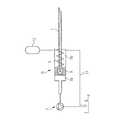
図1は、患者の皮膚100の下に皮下埋め込みされる、機械式の、さらに正確には、液圧機械式の注入装置を示す。注入装置は、先端2を有する針1を備える。先端2は末端で閉じ、横方向に薬剤供給注出口3を有する。針1は、駆動装置Dの作動時、開口管4内に長手方向に変位するように配置されている。 FIG. 1 shows a mechanical, and more precisely a hydromechanical infusion device, implanted subcutaneously under a patient's
管4は皮膚100を貫通し、体外ポンプPに取り付けられている。ポンプPは、模式的に示されているが、種々の形に設計することが可能である。図1に示す実施形態では、患者に供給される注入液が入っている貯蔵器Rは、ポンプPの一部である。また、貯蔵器RはポンプPから分離され、たとえば、図2に主に示されているように、ポンプPに接続されてもよい。しかし、図1の実施形態では、貯蔵器Rから管4を介して針1に向けて注入液をポンプ注入するために、ポンプPのピストン10はピストンロッド状のアクチュエータ11により手動で変位可能である。手動で駆動される代わりに、ポンプはモータ駆動されてもよく、モータは、一定の時間間隔で一定量の薬剤を投薬するように自動的に制御されてもよい。代わりに、貯蔵器R、ポンプPおよび/または上記したモータ、モータ用の自動制御などの薬剤供給システムのその他の構成要素は、注入針1と駆動装置Dとともに埋め込まれてもよい。その他の変形例が可能で、図2〜8を参照して後述される実施形態を考慮すれば明らかとなる。 The tube 4 penetrates the
図1に示す注入装置では、ピストン10が作動して貯蔵器R内の圧力が増加すると、駆動装置Dのばね5の力に逆らって針1が変位する。これにより、針1の先端2は、注入装置の前方に堆積した繊維組織を貫通する。戻しばね5が完全に圧縮され、ピストン10により注入液に加えられる圧力がさらに増加すると、ボール弁6は第1の戻しばね5より強力な第2の戻しばね7に抗して変位する。このように、圧力が十分高いレベルに保たれている限り、注入液は貯蔵器Rから管4、中空針1、針の出口3を介して患者の体内にポンプ注入される。圧力が解除されると、ボール弁6は、戻しばね5、7により閉じられ、針1は図1に示す初期位置に後退する。 In the injection device shown in FIG. 1, when the
針1の外面と管4の内面間は、繊維組織が侵入し生長しないようにぴったりと嵌合する必要がある。 It is necessary to fit between the outer surface of the
なお、針1に作用して針1を前進させる力は、実際の圧力と針1の断面積の積として計算される。典型的な注入針の断面は比較的小さいため、繊維組織を貫通し、戻しばね5、7の反力に打ち勝つため、大きな圧力を加える必要がある。したがって、厳密に分離された2つのチャンバが駆動装置の前後に形成されるように駆動装置Dを構成すると好都合である。これにより、駆動装置Dの後方のチャンバが大気圧程度の低圧に維持されると、針1に作用する力は、実際の圧力と駆動装置Dの全体の断面積との積に一致し、かなり大きくなる。 The force that acts on the
これを図2に示す。駆動装置Dは、図1に示されるように針1が取り付けられたピストン8を備える。ピストン8は、ピストン8の前方の第1のチャンバ9aと、ピストン8の後方の第2のチャンバ9bとを分離する。第1のチャンバ9aの圧力がポンプPにより付勢される圧力に一致するが、第2のチャンバ9bの圧力は低い値に維持される。 This is shown in FIG. The drive device D includes a
たとえば、チャンバ9bは圧縮性ガスで充填することもできる。この場合、圧縮空気がすでに針の後退力を発生しているため、戻しばね5なしで済ますことができる。 For example, the
しかし、ガスチャンバを確実にシールすることは困難である。したがって、第2のチャンバ9bは、気体の代わりに注入液などの液体で満たされ、液体は可撓体積12に圧入されてもよい。可撓体積12は、強力な反力を生じずに充填できるような簡単なバルーンタイプである。または、可撓体積12は、可撓膜により第2のチャンバ9bの液体から区画されるガスチャンバを備えてもよい。この場合も、戻しばね5なしで済ますことができる。 However, it is difficult to securely seal the gas chamber. Therefore, the
可撓体積12の代わりに、導管13により、第2のチャンバ9bと貯蔵器Rとを接続してもよい。これにより、針1を前進させると、液体は第2のチャンバ9bから導管13を介して貯蔵器Rに排出され、針1を戻しばね5により後退させると、液体は貯蔵器Rから導管13を介して第2のチャンバ9bに戻される。 Instead of the
もちろん、ポンプPと貯蔵器Rは、必要な場合、遠隔または単一装置として、駆動装置Dと針1とともに患者の体内に埋め込まれてもよい。 Of course, the pump P and reservoir R may be implanted in the patient's body with the drive D and the
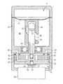
図3は、皮下埋め込みされる、完全埋め込み型、厳密には機械式の注入装置を示す。注入装置の個々の構成要素は、外壁16a、16bを備える一体型本体15に収容される。外壁16a、16bにより区画された体積は、注入液で完全に満たされる。壁部16aは、注入と補充のたびに発生する体積変化を可能にするように可撓である。壁部16aは、充填針の貫通に対して自己封止性であるポリマ材料から作られる。注入装置は、皮下埋め込みされながら、ポリマ壁部16aを貫通して注入液が補充される。 FIG. 3 shows a fully implantable, strictly mechanical infusion device, implanted subcutaneously. The individual components of the injection device are housed in an
外壁部16bは堅牢で、本体15内に収容された個々の構成要素に安定性をもたらす。ウィンドウ領域17は、堅牢な壁部16bに形成され、貫通膜18はウィンドウ領域17内に密封状に圧入される。貫通膜18は、注入針1の貫通に対して自己封止する材料から形成され、注入針はウィンドウ領域17を貫通するように配置されている。 The
針1は、図2を参照して上記したように、ピストン8の前方の第1のチャンバ9aと、ピストン8の後方の第2のチャンバ9bとを分離するピストン8に接続されている。戻しばね5と、戻しばね7を有するボール弁6もまた設けられている。開口部19は、第2のチャンバ9bを貯蔵器Rに接続するように設けられ、第1のチャンバ9a内の圧力が上昇すると、ピストン8は第2のチャンバ9bから開口部19を介して貯蔵器Rに注入液を排出し、貯蔵器Rはおよそ大気圧にある。 As described above with reference to FIG. 2, the
第1のチャンバ9aの圧力は、手動で作動されるプッシュボタン式のアクチュエータ11と単一体として形成されたピストン10を備えるポンプPにより増加される。戻しばね20は、図3に示す初期位置にピストン10を付勢する。流路21は、ピストン10内に、流れ狭窄部22と、ピストン10が摺動可能に配置されるハウジング24の少し上に配置された出口開口部23とともに形成されている。 The pressure in the
図3に示す注入装置は、次のように機能する。皮膚に面するプッシュボタン11が皮下配置されると、患者は戻しばね20の弾性力に逆らってプッシュボタン11を押し下げる。流路21の流れ狭窄部22により、第1のチャンバ9aに収容された注入液は、流路21を介して貯蔵器Rに戻されないが、第2のチャンバ9bから開口部19を介して貯蔵器Rに注入液を排出しながら、ウィンドウ領域17に向けて針1とともにピストン8を付勢する。ピストン8が終端位置にあり、プッシュボタン11がさらに押し下げられると、第1のチャンバ9aの圧力は戻しばね7のばね力に打ち勝つのに十分高いレベルに上昇し、ボール弁6を開き、注入液を中空針1を介して排出し、この間に、針の先端2は貫通膜18とこの表面に堆積した繊維組織とを貫通する。圧力が解除されると、ボール弁6はすぐに閉じ、戻しばね20は、注入針1とともに同時にピストン8を後退位置に引き戻しながら、プッシュボタン11を初期位置に付勢する。戻しばね5は無くてもよく、戻しばね5は安全手段として働くだけとなる。ピストン8が開始位置に到達すると、流路21はプッシュボタン11をさらに上方へ移動させるために必要であり、貯蔵器Rから第1のチャンバ9aに追加注入液を引き込ませ、追加注入液は、注入サイクル中に、患者に供給される注入液量を補償する。 The injection device shown in FIG. 3 functions as follows. When the
図3に示す注入装置は、厳密には機械式であり、ガスチャンバを含まず、ピストン要素8、10に特定の封止を必要としないなどのいくつかの利点がある。 The injection device shown in FIG. 3 is strictly mechanical and has several advantages, such as not including a gas chamber and requiring no specific seal on the
駆動装置Dの前進および後退機能に加えて、図3に示す注入装置の駆動装置はさらに、注入針1の先端を横方向に変位させるための手段を備える。図3の具体的な実施形態では、このような横方向変位手段の具体例を示す。特に、針1は、第2の壁部16bの円形溝26に回転可能に取り付けられたターンテーブル25に取り付けられている。さらに、ガイドピン27は、針1に強固に取り付けられ、外壁15の堅牢な壁部16bに確実に固定されたガイド構造28と協働する。注入針1を前進または後退させると、ガイドピン27はガイド構造28に案内され、注入針1を横方向に変位させ、この横方向変位により円形溝26内でターンテーブル25が回転する。 In addition to the forward and backward functions of the driving device D, the driving device of the injection device shown in FIG. 3 further comprises means for laterally displacing the tip of the
ガイド構造28の原理を、図4を参照してより詳細に説明する。ガイド構造28内の弾性フラップ28a、28bは、注入針1を繰り返し前進および後退させると、ガイド構造28全体を介してガイドピン27を案内する。ガイド構造28は、貫通膜18に隣接して配置された血管200へ貫通膜18を貫通して10個の異なる注入部位を設けるように設計されている。必要に応じて、ガイド構造28の軌道は、ガイドピン27を図4に示す開始位置に戻す戻し通路28cを含んでもよい。このような戻し作用は、堅牢な第2の壁部16bに固定された戻しばね29により引き起こされる。 The principle of the
なお、図3に示す注入装置の全ての構成要素がポリマ材料から形成されてもよいが、少なくとも注入針1と戻しばね5、7、20、29は不活性金属から形成されることが好ましい。 Although all the components of the injection apparatus shown in FIG. 3 may be formed of a polymer material, it is preferable that at least the
図5は、複合材料で形成される貫通膜17の好ましい実施形態を示す。この同一複合材料はまた、外側本体15の可撓性の第1の壁部16a、または、本発明の別の実施形態に関連して説明される注入ポート用に用いられる。図5に示す貫通膜17の複合材料は、自己封止軟質材料17bが収容される体積を区画する形状付与層17aを備える。自己封止軟質材料17bは、形状付与層17aの貫通時、注入針1による貫通口を流れない程度の粘性を有するゲルタイプである。単一の形状付与層17aの代わりに、形状付与層17aは複数の層を備えてもよい。
外形状付与層17aはシリコンおよび/またはポリウレタンを含む。なぜなら、そのような物質は注入針1によって生ずる貫通孔を自己封止する性質を有している。FIG. 5 shows a preferred embodiment of the penetrating
The outer shape imparting layer 17a includes silicon and / or polyurethane. This is because such a substance has a property of self-sealing a through hole formed by the
図6は、本発明による注入装置の完全自動化された実施形態を示す。しかし、上記した手動操作要素と、ここに説明される自動操作要素は、可能な場合、組み合わされ交換可能である。図6は薬剤供給システム全体を模式的に示したものであり、患者の皮膚100の下に配置された全ての構成要素は埋め込み型注入装置の一部であり、患者の皮膚100上の構成要素は薬剤供給システムを完成するのに必要である。 FIG. 6 shows a fully automated embodiment of the injection device according to the invention. However, the manual operation elements described above and the automatic operation elements described herein can be combined and exchanged where possible. FIG. 6 schematically illustrates the entire drug delivery system, where all components placed under the patient's
モータMにより駆動されたポンプPは、前進時に本体15の貫通膜17を貫通するように、貯蔵器Rは本体15内の駆動装置Dに取り付けられた注入針1と接続される。流体導管4は、注入針1の前進を補償するのに十分な長さを有する。駆動装置Dは、上記した実施形態同様に、ポンプPにより発生される力により液圧式に作動されるが、別のモータが駆動装置Dを作動するように設けられてもよい。一方、モータMは、駆動装置Dを作動するように設計され、駆動装置Dが動くと、ポンプPが注入作動するように設計されている。 The reservoir R is connected to the
図6に示す実施形態は様々な貯蔵器の種類のうちの1つを備えるが、特定の種類の貯蔵器について説明する。図6に示す貯蔵器Rの体積は、膜60により2つの部分に分割されている。一方の部分はガスで満たされ、もう一方の部分は注入液で満たされる。注入ポート61を経由して、貯蔵器Rには補給針により注入液が補充される。貯蔵器Rが充填されると、ガス部分は大気圧、または、過剰圧にある。各注入サイクル時、注入液が貯蔵器Rから引き出されると、ガス部分の圧力は大気圧以下、すなわち、負の相対値に減少する。ポンプPの種類によっては、ポンプPから貯蔵器Rへの逆流を防止するように単一作用のボール弁62が設けられることは好都合である。 Although the embodiment shown in FIG. 6 comprises one of various reservoir types, a particular type of reservoir will be described. The volume of the reservoir R shown in FIG. 6 is divided into two parts by the
モータMは患者の体外から制御装置Cによりワイヤレスに制御される。制御装置Cは、注入サイクル間の時間間隔と、各注入サイクル時患者の体内に注入される注入液の量とを決定する。制御装置CとモータM間のワイヤレス通信の代わりに、電気接点が皮膚100を介して設けられてもよい。また、制御装置Cは、モータMとともに埋め込まれてもよい。この場合、変更要求に従って制御装置の適正な構成を可能にするように、制御装置Cは、無線により、または、電気接点を介して、患者の体外からプログラム可能であることが好ましい。 The motor M is wirelessly controlled by the control device C from outside the patient's body. Controller C determines the time interval between infusion cycles and the amount of infusate to be infused into the patient's body during each infusion cycle. Instead of wireless communication between the controller C and the motor M, electrical contacts may be provided through the
制御装置Cに加えて、または、これの代わりに、モータMを作動するための感圧スイッチが皮下配置されてもよい。 In addition to or instead of the control device C, a pressure-sensitive switch for operating the motor M may be arranged subcutaneously.
モータMにエネルギを供給する様々な方法がある。たとえば、エネルギは、モータMにより直接使用される際および/または再充電可能な電池および/またはキャパシタなどのアキュムレータAを充電する際、患者の体外から供給されてもよい。図6に示す実施形態では、体外1次エネルギ源Eは、第1の形態のエネルギを電気エネルギなどの第2の形態のエネルギに変換するエネルギ変換装置Tに、患者の皮膚100を介して第1の形態のエネルギを伝達する。電気エネルギは、要求に応じて、モータMに2次エネルギを供給するアキュムレータAを再充電するのに用いられる。 There are various ways of supplying energy to the motor M. For example, energy may be supplied from outside the patient's body when used directly by the motor M and / or when charging an accumulator A such as a rechargeable battery and / or capacitor. In the embodiment shown in FIG. 6, the extracorporeal primary energy source E passes through the patient's
一般に、外部エネルギ源Eは、電磁場、磁場、電場などの外部場を発生させるか、または、電磁波信号または音波信号などの波動信号を発生させる。たとえば、図6に示されるようなエネルギ変換装置Tは、太陽電池として作用するが、1次エネルギ源Eの特定の波動信号で構成されていてもよい。エネルギ変換装置Tはまた、温度変化を電気エネルギに変換するように構成されていてもよい。 Generally, the external energy source E generates an external field such as an electromagnetic field, a magnetic field, and an electric field, or generates a wave signal such as an electromagnetic wave signal or a sound wave signal. For example, the energy conversion device T as shown in FIG. 6 acts as a solar cell, but may be constituted by a specific wave signal of the primary energy source E. The energy conversion device T may also be configured to convert temperature changes into electrical energy.
外部1次エネルギ源Eの代わりに、アキュムレータAの代わりの通常の長寿命電池などの埋め込み型1次エネルギ源Eが用いられてもよい。 Instead of the external primary energy source E, an embedded primary energy source E such as a normal long-life battery instead of the accumulator A may be used.
エネルギ信号はまた、エネルギの送信が無線または有線にかかわらず、エネルギ信号を適切に変調させることにより制御装置Cの制御信号を送信するのに用いられ、エネルギ信号は、ディジタル制御信号またはアナログ制御信号のための搬送波信号を兼ねる。特に、制御信号は、周波数、位相および/または振幅変調信号であってよい。 The energy signal is also used to transmit the control signal of the controller C by appropriately modulating the energy signal regardless of whether the energy transmission is wireless or wired, the energy signal being a digital control signal or an analog control signal. Also serves as a carrier signal for In particular, the control signal may be a frequency, phase and / or amplitude modulated signal.
図7は、図6に示す配置に関連して用いられるモータ−ポンプ装置の断面図を示す。このモータ−ポンプ装置は、WO2004/012806A1に広範に説明されており、これに開示される他のポンプ装置もまた同様に、本発明に関連して用いられる。モータ−ポンプ装置は弁ポンプアセンブリを備える。膜ポンプPと弁ポンプ装置30は、該アセンブリの2つの主要な要素を構成し、それぞれ円筒ハウジング31に取り付けられる。弁装置30は、ハウジング31に静止して取り付けられ固定されたセラミックディスク32の形状をした第1の弁部材と、セラミックディスク32に向かい合って接触し、固定ディスク32に対して回転可能なセラミックディスク33の形状をした第2の弁部材とを備える。モータ34は、セラミックディスク32、33を囲むハウジング31に取り付けられている。モータ34は、回転可能なディスク33に下部中心孔の対応するスプラインに連結されるスプラインモータ軸を含み、ディスク33はモータ34の回転に従うが、ディスク33をモータ軸35に対して軸方向にわずかに移動可能にしている。モータ軸35には、停止部材36と、ディスク33に対してわずかな量の圧力を付勢し、固定ディスク32に対してディスク33を付勢するばね座金37とが取り付けられている。 FIG. 7 shows a cross-sectional view of the motor-pump device used in connection with the arrangement shown in FIG. This motor-pump device is extensively described in WO2004 / 012806A1, and other pump devices disclosed therein are also used in connection with the present invention. The motor-pump device includes a valve pump assembly. The membrane pump P and the
ポンプPは、どんな種類の膜であってもよいポンプ膜47を含む。好ましくは、膜47は、金属膜、たとえば、チタニウム膜、または、長寿命が得られて、経時的に膜47を介して液体が拡散するのを回避するために、プラスチック材料で被覆されている。弁ポンプアセンブリに内蔵された本実施形態においては、操作装置は、対向する2つのカム表面49付きの切り欠き溝を有するカムスリーブ48と、カム表面49を押圧し、切り欠き溝内で回転するカムホイール50と、回転ディスク33に接続されたポンプ軸51とを備える。カムホイール50は、カムホイール軸52を介してポンプ軸51に取り付けられている。ポンプ軸51は回転可能なディスク33の上部中心孔53の一致するスプラインに連結されているスプライン軸57を介して回転ディスク33に接続されているため、ポンプ軸51は回転する。上記したスプライン連結により、ディスク33はポンプ軸51に対して軸方向にいくらか移動可能である。ポンプ軸51は、封入されたボール軸受54に取り付けられ、ボール軸受54に対して軸方向に固定されている。ポンプ軸51上の複数の細長い溝55は、ボール軸受54を通過して、固定ディスク32の第1のチャネル38と膜47下のポンプチャンバ56の間の液体流路としての役割をはたす。 The pump P includes a
モータ34が回転しているとき、膜47は上下に動く。膜47が上下に動いている時、回転可能なディスク33は第1のチャネル38を第2のチャネル40と第3のチャネル41とに交互に接続し、液体が、第2のチャネル40または第3のチャネル41からポンプチャンバ56に送られるか、または、第2のチャネル40または第3のチャネル41によりポンプチャンバ52から受け取られる。図7では、第2のチャネル40がチャンバ56から第1のチャネル38を介して液体を受け取るように、第1のチャネル38は開口チャネル46を介して第2のチャネルに接続された形で示されている。 When the
ディスク32、33用に選択される材料は、ディスクが経時的に互いに固着しないように極めて小さい公差で機能できる必要があるため重要である。この目的に適する市販の材料として、たとえば、セラミック、または、その他の材料たとえば炭素繊維などと混合されたセラミックが例示される。 The material selected for the
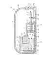
図8は、注入装置が自動的に駆動され、注入装置の全ての構成要素が外側本体15に収容される、本発明の第3の実施形態を示す。注入装置は、血管200を本体15に近接して維持するための血管200のホルダ90としての横方向伸張部分を有する、実質的にディスク形状をしている。図8に示す注入装置は皮下埋め込みされていて、患者の皮膚100にあるウィンドウを介して見たものである。皮膚100は、ディスク形状の注入装置の平らな表面を覆っている。 FIG. 8 shows a third embodiment of the invention in which the injection device is automatically driven and all components of the injection device are housed in the
注入針1は、駆動装置Dの一部であるターンテーブルに取り付けられる。ターンテーブルが回転すると、注入針1の先端は、血管200に近接したウィンドウ18に沿って横方向に移動する。特に、注入針1は、軸方向に前後に可動するようにターンテーブルに取り付けられ、先端がウィンドーに対してある傾斜角を有してウィンドウ18を通過する。この傾斜角があるので、注入針1の先端は、ウィンドウ18を通過して血管200の内部にまで進んだとき、血管200の対向する境界を貫通することはない。ホルダ90は、注入針が貫通かつ注入する時、血管200を支持する。 The
本体15の内部は貯蔵器Rを兼ねる。または、貯蔵器Rは、本体15内か、好ましくは、本体15の外壁の一部を構成する周縁の一部とともに、密閉されたチャンバとして設けられてもよい。このような周縁部分が可撓材料から作られる場合、このような可撓性は貯蔵器Rの体積変化を補償できる。しかし、少なくとも注入ポート61は、貯蔵器Rを充填するために設けられる。 The inside of the
注入針は、縦方向と横方向の両方の変位のために駆動装置Dに取り付けられ、ポンプPは貯蔵器Rと注入針1とを接続している。 The injection needle is attached to the drive D for both longitudinal and lateral displacement, and the pump P connects the reservoir R and the
ポンプPは、第1のモータMにより駆動され、駆動装置Dは第2のモータMにより駆動される。または、単一モータMを、ポンプPと駆動装置Dの両方を駆動するのに用いてもよい。また、上記のように、ポンプPが作動すると、駆動装置Dが同時に作動する。または、駆動装置Dを作動すると、ポンプPが作動するようにしてもよい。 The pump P is driven by the first motor M, and the driving device D is driven by the second motor M. Alternatively, a single motor M may be used to drive both the pump P and the drive device D. Further, as described above, when the pump P is activated, the drive device D is activated simultaneously. Alternatively, when the driving device D is operated, the pump P may be operated.
長寿命電池Bは、2つのモータMにエネルギを供給するように設けられる。または、再充電可能な電池などのアキュムレータは、長寿命電池Bの代わりに用いられてもよい。 The long-life battery B is provided to supply energy to the two motors M. Alternatively, an accumulator such as a rechargeable battery may be used instead of the long-life battery B.
さらに、制御装置Cは、2つのモータMを制御するように設けられる。図8に示す実施形態では、制御装置Cは、外部データ処理装置80により、患者の体外からプログラム可能である。データ処理装置80と制御装置Cの間のデータ交換は、患者の体外から制御装置Cへデータをワイヤレスで送信するための埋め込まれたデータ送信インタフェースを介して無線で行うことが好ましいが、必要ならば、患者の皮膚を貫通して有線で行うこともできる。さらに、データ交換は、制御装置Cからデータ処理装置80へのデータ送信を可能にするように双方向通信できることが好ましい。このようなデータは、注入装置の性能、実行する注入サイクル数、貯蔵器Rの充填状態などについてのデータを含んでもよい。 Furthermore, the control device C is provided to control the two motors M. In the embodiment shown in FIG. 8, the controller C can be programmed from outside the patient's body by the
図8の注入装置はさらに、図8に示す実施形態のように、血管200内に配置され、生理学的パラメータを検出するフィードバックセンサFを含んでもよい。このようなパラメータは制御装置Cに送られ、注入サイクルを促進するための対応する制御プログラムに用いられてもよい。代わりに、または、さらに、生理学的パラメータは、外部データ処理装置80に転送され、医師が適正な診断ができるようにしてもよい。最終的には、医師はデータ処理装置80を用いて、フィードバックセンサFにより送られた生理学的パラメータにしたがって、制御装置Cを調整する。いずれの種類の患者の身体パラメータ、または、注入装置の処理パラメータも、制御装置に送り返され、制御装置はこの結果により注入装置を制御する。 The infusion device of FIG. 8 may further include a feedback sensor F disposed within the
図8は、注入装置が自動的に駆動され、注入装置の全ての構成要素が外側本体15に収容されている本発明の第3の実施形態を示すが、各種構成要素のうち1つ以上が電池Bなどのように外側本体15から分離されて埋め込まれるか、または制御装置Cなどのように患者の体外で埋め込まれる。また、ポンプPおよび/または貯蔵器Rは、外側本体15に別々に接続されてもよく、好ましくは、外側本体15に近接して取り付けられてもよい。図8に具体的に示されていない構成要素は、上記実施形態で説明されたものか、または異なるものであってもよい。 FIG. 8 shows a third embodiment of the invention in which the injection device is automatically driven and all components of the injection device are housed in the
患者の体内に上記した注入装置のいずれか1つを埋め込むことによりヒトまたは動物を治療する方法は、
皮膚を切開するステップと、
患者の体内の、該注入装置の埋め込みのための適正位置を任意切開するステップと、
前記適正位置に該注入装置を配置するステップと、
該注入装置の配置後、少なくとも該皮膚を閉じるステップと
を含む。A method of treating a human or animal by implanting any one of the infusion devices described above in a patient's body comprises:
Incising the skin;
Arbitrarily incising an appropriate location in the patient's body for implantation of the infusion device;
Placing the infusion device in the proper location;
And at least closing the skin after placement of the infusion device.
皮膚を閉じるには、たとえば、縫合、テーピング、およびその他の適切な技術を含んでもよい。注入装置は、患者の体内または脂肪組織内に皮下配置されるか、または、筋内に配置されてもよい。注入液を循環血液に直接注入するため、注入装置を血管(200)に隣接して配置する場合、埋め込みのための適正位置を任意切開するステップは、各血管を任意切開し、血管に隣接して注入装置を配置することを含む。血管は、注入装置に接続されたホルダ90により注入装置に固定されてもよい。 Closing the skin may include, for example, suturing, taping, and other suitable techniques. The infusion device may be placed subcutaneously in the patient's body or adipose tissue, or placed in muscle. If the infusion device is placed adjacent to the blood vessel (200) in order to inject the infusate directly into the circulating blood, the step of arbitrarily dissecting the appropriate position for implantation is to arbitrarily dissect each blood vessel and adjacent to the blood vessel. Placing an infusion device. The blood vessel may be secured to the infusion device by a
注入装置は、患者の胃腸管または尿管内に、または隣接して配置されてもよい。注入装置を胃腸管または尿管に隣接して配置する場合、注入装置に接続されたホルダにより胃腸管または尿管に固定されてもよい。さらなる別法として、注入装置は、患者の胸郭または患者の腹部に配置されてもよい。 The infusion device may be placed in or adjacent to the patient's gastrointestinal or ureteral tract. When the injection device is placed adjacent to the gastrointestinal tract or ureter, it may be secured to the gastrointestinal tract or ureter by a holder connected to the injection device. As a further alternative, the infusion device may be placed in the patient's rib cage or in the patient's abdomen.
注入装置が血管に隣接して、または、患者の胃腸管もしくは尿管に隣接して、もしくは患者の胃腸管内もしくは尿管内に、または、患者の胸郭内もしくは腹部内に配置される場合、皮膚を切開し、埋め込みのための適正位置を任意切開し、前記適正位置に注入装置を配置するステップは、
該注入装置が該患者の胸郭または腹部に埋め込まれる場合、ヴェレス針または別の種類のガス膨脹針を該腹部腔または胸郭腔に挿入し、該腹部腔または胸郭腔をガスで満たすことと、
鍵穴状開口部を切開することと、
該鍵穴状開口部を介して該適性位置に向けて少なくとも1つの套管針を挿入することと、
該少なくとも1つの套管針を介して前記位置に向けて1つ以上の医療器具とカメラを前進させることと、
上記位置を切開することと、
該少なくとも1つの套管針または皮膚内の切開部分を介して前記位置に該注入装置またはこの一部を供給することと
を含む。If the infusion device is placed adjacent to the blood vessel, or adjacent to the patient's gastrointestinal or ureter, or within the patient's gastrointestinal or ureter, or within the patient's rib cage or abdomen, Incising, arbitrarily opening an appropriate position for implantation, and placing the injection device at the appropriate position,
When the infusion device is implanted in the patient's thorax or abdomen, a Velez needle or another type of gas inflation needle is inserted into the abdominal cavity or thorax cavity, and the abdominal cavity or thorax cavity is filled with gas;
Incising the keyhole-shaped opening;
Inserting at least one trocar through the keyhole opening toward the appropriate position;
Advancing one or more medical instruments and cameras toward the position via the at least one trocar;
Incising the position,
Delivering the infusion device or part thereof to the location via the at least one trocar or incision in the skin.
たとえば、貯蔵器Rは、前記方法で腹部腔または胸郭腔に配置されてもよい。また、注入装置または貯蔵器Rなどの注入装置の一部は、開口手術で埋め込まれてもよく、この場合、胸郭壁または腹部壁が、患者の胸郭または腹部内の適正位置に注入装置を配置するため開口され、その後、皮膚とその他の組織層は、縫合などにより閉じられ、好ましくは層状に縫合される。 For example, the reservoir R may be placed in the abdominal cavity or thoracic cavity in the manner described above. Also, a portion of the infusion device, such as the infusion device or reservoir R, may be implanted with open surgery, in which case the thoracic wall or abdominal wall places the infusion device in the proper position within the patient's thorax or abdomen. The skin and other tissue layers are then closed, such as by suturing, and preferably sutured in layers.
貯蔵器Rを充填することは、好ましくは、該貯蔵器の周縁に接続および/または一体化された注入ポートを通過して一定量の注入液を注入するステップを含む。 Filling reservoir R preferably includes injecting a volume of infusate through an infusion port connected and / or integrated to the periphery of the reservoir.
注入装置の以下の要素、
駆動装置Dを作動させるためのモータMと、
モータMにエネルギを供給するエネルギ貯蔵手段Bであって、電池、キャパシタ、および再充電可能な電池のうち少なくとも1つを備える手段と、
接触式にエネルギをモータMに伝達するための、外部エネルギ源Eまたはエネルギ貯蔵手段BとモータM間の電気結合要素90と、
モータMもしくはエネルギ貯蔵手段B、または、両方を、体外1次エネルギ源Eに接続し、モータMもしくはエネルギ貯蔵手段B、または、両方に、非接触式にエネルギを伝達するためのワイヤレスな結合手段と、
モータMを制御するための制御装置Cと、
ワイヤレスなエネルギ伝達または受取手段と、
外部データ処理装置80から制御装置Cへデータをワイヤレス送信するためのデータ送信インタフェースと、
フィードバックセンサFと、
該注入液を保持するための貯蔵器Rと、
貯蔵器を充填するための注入ポート61
のうち1つ以上の要素は、少なくとも駆動装置Dと注入針1から遠くに埋め込まれてもよい。The following elements of the injection device,
A motor M for operating the drive device D;
Energy storage means B for supplying energy to the motor M, the means comprising at least one of a battery, a capacitor, and a rechargeable battery;
An
Wireless coupling means for connecting the motor M or the energy storage means B or both to the extracorporeal primary energy source E and transferring the energy to the motor M or the energy storage means B or both in a non-contact manner. When,
A control device C for controlling the motor M;
Wireless energy transmission or reception means;
A data transmission interface for wirelessly transmitting data from the external
A feedback sensor F;
A reservoir R for holding the infusate;
One or more of the elements may be implanted at least remotely from the drive device D and the
Claims (7)
Translated fromJapanese先端(2)を有する注入針(1)と、
該注入針に結合され、且つ注入装置が患者の体内に埋め込まれるときに、該注入針の軸方向に沿って該先端を前進及び後退させて繊維組織を貫通するように配置される駆動装置(D)とを備え、
前記注入針と駆動装置は、患者の体内に埋め込まれるように設計されている注入装置であって、
該注入針(1)の該先端(2)を、該注入装置の本体(15)内で、横方向に変位可能とすることにより、注入部位を変更できるようにしたことを特徴とする注入装置。A body (15);
An injection needle (1) having a tip (2);
The injection needle is attached, andwhen the infusion device is implanted in the patient's body, a driving device arranged tobe advanced and retracted the tipalong the axial direction of the infusion needle to penetrate the fibrous tissue ( D)
The infusion needle and drive device is an infusion device designed to be implanted in a patient's body,
An injection device characterizedin that the injection site can be changed by allowing the tip (2) of the injection needle (1) to be displaced laterally within the main body (15) of the injection device. .
Applications Claiming Priority (3)
| Application Number | Priority Date | Filing Date | Title |
|---|---|---|---|
| US73274005P | 2005-11-02 | 2005-11-02 | |
| US60/732,740 | 2005-11-02 | ||
| PCT/EP2006/010349WO2007051563A1 (en) | 2005-11-02 | 2006-10-26 | Implantable infusion device with advanceable and retractable needle |
Publications (3)
| Publication Number | Publication Date |
|---|---|
| JP2009514580A JP2009514580A (en) | 2009-04-09 |
| JP2009514580A5 JP2009514580A5 (en) | 2009-12-10 |
| JP5072850B2true JP5072850B2 (en) | 2012-11-14 |
Family
ID=37672465
Family Applications (1)
| Application Number | Title | Priority Date | Filing Date |
|---|---|---|---|
| JP2008538289AActiveJP5072850B2 (en) | 2005-11-02 | 2006-10-26 | Implantable injection device |
Country Status (17)
| Country | Link |
|---|---|
| US (4) | US9504785B2 (en) |
| EP (6) | EP1960027B1 (en) |
| JP (1) | JP5072850B2 (en) |
| CN (2) | CN102488938B (en) |
| AT (2) | ATE541600T1 (en) |
| AU (1) | AU2006310807B2 (en) |
| CA (1) | CA2625954C (en) |
| DE (1) | DE602006014197D1 (en) |
| DK (1) | DK2926847T3 (en) |
| ES (4) | ES2346244T3 (en) |
| HU (1) | HUE059454T2 (en) |
| LT (1) | LT2926847T (en) |
| MX (1) | MX2008005895A (en) |
| PL (1) | PL2926847T3 (en) |
| PT (1) | PT2926847T (en) |
| SI (1) | SI2926847T1 (en) |
| WO (1) | WO2007051563A1 (en) |
Families Citing this family (167)
| Publication number | Priority date | Publication date | Assignee | Title |
|---|---|---|---|---|
| US6464628B1 (en) | 1999-08-12 | 2002-10-15 | Obtech Medical Ag | Mechanical anal incontinence |
| US6482145B1 (en) | 2000-02-14 | 2002-11-19 | Obtech Medical Ag | Hydraulic anal incontinence treatment |
| US6471635B1 (en) | 2000-02-10 | 2002-10-29 | Obtech Medical Ag | Anal incontinence disease treatment with controlled wireless energy supply |
| US6450173B1 (en) | 1999-08-12 | 2002-09-17 | Obtech Medical Ag | Heartburn and reflux disease treatment with controlled wireless energy supply |
| CA2635435C (en) | 2000-02-10 | 2010-05-25 | Potencia Medical Ag | Controlled urinary incontinence treatment |
| ATE391468T1 (en) | 2000-02-10 | 2008-04-15 | Potencia Medical Ag | MECHANICAL DEVICE FOR IMPOTENCY TREATMENT |
| AU764705B2 (en)* | 2000-02-10 | 2003-08-28 | Implantica Patent Ltd. | Urinary incontinence treatment with wireless energy supply |
| ATE416743T1 (en) | 2000-02-11 | 2008-12-15 | Potentica Ag | DEVICE WITH ENERGY CONVERSION MEANS FOR TREATING IMPOTENCY |
| CA2396224C (en) | 2000-02-11 | 2011-07-12 | Potencia Medical Ag | Controlled impotence treatment |
| WO2001047440A2 (en) | 2000-02-14 | 2001-07-05 | Potencia Medical Ag | Male impotence prosthesis apparatus with wireless energy supply |
| US20030100929A1 (en) | 2000-02-14 | 2003-05-29 | Peter Forsell | Controlled penile prosthesis |
| US7442165B2 (en) | 2000-02-14 | 2008-10-28 | Obtech Medical Ag | Penile prosthesis |
| EP1762259B2 (en) | 2005-09-12 | 2025-01-01 | Unomedical A/S | Inserter for an infusion set with a first and second spring units |
| JP5072850B2 (en) | 2005-11-02 | 2012-11-14 | インジェクティカ アーゲー | Implantable injection device |
| EP2037999B1 (en) | 2006-07-07 | 2016-12-28 | Proteus Digital Health, Inc. | Smart parenteral administration system |
| US9345836B2 (en) | 2007-10-02 | 2016-05-24 | Medimop Medical Projects Ltd. | Disengagement resistant telescoping assembly and unidirectional method of assembly for such |
| BRPI0817907B8 (en) | 2007-10-02 | 2021-06-22 | Lamodel Ltd | apparatus for administering a substance to an individual |
| US9656019B2 (en) | 2007-10-02 | 2017-05-23 | Medimop Medical Projects Ltd. | Apparatuses for securing components of a drug delivery system during transport and methods of using same |
| US7967795B1 (en) | 2010-01-19 | 2011-06-28 | Lamodel Ltd. | Cartridge interface assembly with driving plunger |
| US10420880B2 (en) | 2007-10-02 | 2019-09-24 | West Pharma. Services IL, Ltd. | Key for securing components of a drug delivery system during assembly and/or transport and methods of using same |
| US9125979B2 (en) | 2007-10-25 | 2015-09-08 | Proteus Digital Health, Inc. | Fluid transfer port information system |
| US8419638B2 (en) | 2007-11-19 | 2013-04-16 | Proteus Digital Health, Inc. | Body-associated fluid transport structure evaluation devices |
| US8280484B2 (en) | 2007-12-18 | 2012-10-02 | The Invention Science Fund I, Llc | System, devices, and methods for detecting occlusions in a biological subject |
| US9672471B2 (en) | 2007-12-18 | 2017-06-06 | Gearbox Llc | Systems, devices, and methods for detecting occlusions in a biological subject including spectral learning |
| US9717896B2 (en) | 2007-12-18 | 2017-08-01 | Gearbox, Llc | Treatment indications informed by a priori implant information |
| US20090292212A1 (en)* | 2008-05-20 | 2009-11-26 | Searete Llc, A Limited Corporation Of The State Of Delaware | Circulatory monitoring systems and methods |
| US20090287120A1 (en) | 2007-12-18 | 2009-11-19 | Searete Llc, A Limited Liability Corporation Of The State Of Delaware | Circulatory monitoring systems and methods |
| US8636670B2 (en) | 2008-05-13 | 2014-01-28 | The Invention Science Fund I, Llc | Circulatory monitoring systems and methods |
| WO2009096851A1 (en) | 2008-01-28 | 2009-08-06 | Milux Holding Sa | A drainage device comprising a filter cleaning device |
| MX2010008003A (en) | 2008-01-29 | 2010-09-24 | Milux Holding Sa | Apparatus for treating obesity. |
| GB0809361D0 (en)* | 2008-05-22 | 2008-07-02 | Cellerix Sa | Injection device |
| DE102008002396A1 (en) | 2008-06-12 | 2009-12-17 | Biotronik Vi Patent Ag | Implantable drug reservoir and device with an implantable drug reservoir |
| US9393369B2 (en) | 2008-09-15 | 2016-07-19 | Medimop Medical Projects Ltd. | Stabilized pen injector |
| US12097357B2 (en) | 2008-09-15 | 2024-09-24 | West Pharma. Services IL, Ltd. | Stabilized pen injector |
| AU2009302955B2 (en) | 2008-10-10 | 2017-01-05 | Implantica Patent Ltd. | Fastening means for implantable medical control assembly |
| SMT202100713T1 (en)* | 2008-10-10 | 2022-01-10 | Medicaltree Patent Ltd | Infusion of drugs |
| ES2576462T3 (en) | 2008-10-10 | 2016-07-07 | Kirk Promotion Ltd. | Stimulation of penis erection |
| US8852153B2 (en) | 2008-10-10 | 2014-10-07 | Peter Forsell | Stimulation of penis erection |
| US8945054B2 (en) | 2008-10-10 | 2015-02-03 | Peter Forsell | Infusion of drugs |
| CN105056336B (en)* | 2008-10-10 | 2019-09-13 | 医树专利有限公司 | drug infusion |
| US9750874B2 (en)* | 2008-10-10 | 2017-09-05 | Peter Forsell | Stimulation of penis erection |
| WO2010042018A1 (en) | 2008-10-10 | 2010-04-15 | Milux Holding S.A. | Heart help device, system and method |
| US9192474B2 (en) | 2008-10-10 | 2015-11-24 | Peter Forsell | Stimulation of penis erection |
| EP2373258B1 (en) | 2008-10-10 | 2013-06-12 | Milux Holding SA | Infusion of drugs |
| US9579202B2 (en)* | 2008-10-10 | 2017-02-28 | Peter Forsell | Infusion of drugs |
| EP2373256B1 (en)* | 2008-10-10 | 2016-06-08 | Kirk Promotion LTD. | Stimulation of penis erection |
| US8926572B2 (en) | 2008-10-10 | 2015-01-06 | Peter Forsell | Stimulation of sexually responsive tissue of the vulva |
| ES2566007T3 (en) | 2008-10-10 | 2016-04-08 | Kirk Promotion Ltd. | Stimulation of penis erection |
| EP2344106B8 (en)* | 2008-10-10 | 2022-07-20 | MedicalTree Patent Ltd. | Heart help device |
| US11224513B2 (en)* | 2008-10-10 | 2022-01-18 | Peter Forsell | Stimulation of penis erection |
| EP3851076A1 (en) | 2008-10-10 | 2021-07-21 | MedicalTree Patent Ltd. | An improved artificial valve |
| WO2010040551A2 (en) | 2008-10-10 | 2010-04-15 | Milux Holding Sa | Infusion of drugs |
| US8475355B2 (en)* | 2008-10-10 | 2013-07-02 | Milux Holding S.A. | Heart help device, system, and method |
| US10668196B2 (en)* | 2008-10-10 | 2020-06-02 | Peter Forsell | Heart assisting device |
| WO2010042011A1 (en)* | 2008-10-10 | 2010-04-15 | Milux Holding Sa | Heart help device, system, and method |
| EP2349384B1 (en)* | 2008-10-10 | 2021-03-17 | MedicalTree Patent Ltd. | Heart help device system |
| US8874215B2 (en) | 2008-10-10 | 2014-10-28 | Peter Forsell | System, an apparatus, and a method for treating a sexual dysfunctional female patient |
| US8900218B2 (en)* | 2008-10-10 | 2014-12-02 | Peter Forsell | Infusion of drugs |
| EP2373257B1 (en)* | 2008-10-10 | 2018-07-25 | Kirk Promotion LTD. | Stimulation of penis erection |
| US8152779B2 (en) | 2008-12-30 | 2012-04-10 | Medimop Medical Projects Ltd. | Needle assembly for drug pump |
| US20100237096A1 (en)* | 2009-03-17 | 2010-09-23 | Gojo Industries, Inc. | Wirelessly-powered dispenser system |
| AU2010226326B2 (en)* | 2009-03-20 | 2015-11-26 | Incube Labs, Llc | Solid drug delivery apparatus, formulations and methods of use |
| KR20220000916A (en)* | 2009-07-10 | 2022-01-04 | 메디칼트리 페이턴트 엘티디. | Implantable Lubrication Device |
| AU2020223742B2 (en)* | 2009-07-10 | 2022-01-13 | Medicaltree Patent Ltd | Implantable Lubrication Device and Method of Treating a Human or Mammal Patient by Means of the Device |
| RU2712082C2 (en)* | 2009-07-10 | 2020-01-24 | МедикалТри Патент Лтд. | Implantable lubricating device |
| JP5977391B2 (en)* | 2009-07-10 | 2016-08-24 | ミルックス・ホールディング・エスエイ | Medical device implanted in the patient's hip joint |
| CA3066331C (en)* | 2009-07-10 | 2022-11-29 | Medicaltree Patent Ltd. | Implantable lubrication device and method of treating a human or mammal patient by means of the device |
| US11224516B2 (en)* | 2009-07-10 | 2022-01-18 | Peter Forsell | Hip joint device and method |
| CA2805030C (en)* | 2009-07-10 | 2020-05-05 | Milux Holding S.A. | Implantable lubrication device and method of treating a human or mammal patient by means of the device |
| US10952836B2 (en) | 2009-07-17 | 2021-03-23 | Peter Forsell | Vaginal operation method for the treatment of urinary incontinence in women |
| US9949812B2 (en) | 2009-07-17 | 2018-04-24 | Peter Forsell | Vaginal operation method for the treatment of anal incontinence in women |
| US8784389B2 (en)* | 2009-08-31 | 2014-07-22 | Beta-O2 Technologies Ltd. | Oxygen supply for implantable medical device |
| US10071196B2 (en) | 2012-05-15 | 2018-09-11 | West Pharma. Services IL, Ltd. | Method for selectively powering a battery-operated drug-delivery device and device therefor |
| US10071198B2 (en) | 2012-11-02 | 2018-09-11 | West Pharma. Servicees IL, Ltd. | Adhesive structure for medical device |
| US8157769B2 (en) | 2009-09-15 | 2012-04-17 | Medimop Medical Projects Ltd. | Cartridge insertion assembly for drug delivery system |
| US8377034B2 (en) | 2009-12-04 | 2013-02-19 | Std Med, Inc. | Vascular access port |
| US8348898B2 (en) | 2010-01-19 | 2013-01-08 | Medimop Medical Projects Ltd. | Automatic needle for drug pump |
| BR112012019212A2 (en) | 2010-02-01 | 2017-06-13 | Proteus Digital Health Inc | data collection system |
| EP2531096A4 (en) | 2010-02-01 | 2013-09-11 | Proteus Digital Health Inc | Two-wrist data gathering system |
| US8594806B2 (en) | 2010-04-30 | 2013-11-26 | Cyberonics, Inc. | Recharging and communication lead for an implantable device |
| EP2569031B1 (en) | 2010-05-10 | 2017-10-11 | Medimop Medical Projects Ltd. | Low volume accurate injector |
| US9737657B2 (en) | 2010-06-03 | 2017-08-22 | Medtronic, Inc. | Implantable medical pump with pressure sensor |
| US8397578B2 (en) | 2010-06-03 | 2013-03-19 | Medtronic, Inc. | Capacitive pressure sensor assembly |
| US8603134B2 (en)* | 2011-01-14 | 2013-12-10 | Covidien Lp | Latch mechanism for surgical instruments |
| US8945175B2 (en) | 2011-01-14 | 2015-02-03 | Covidien Lp | Latch mechanism for surgical instruments |
| USD702834S1 (en) | 2011-03-22 | 2014-04-15 | Medimop Medical Projects Ltd. | Cartridge for use in injection device |
| US20140155698A1 (en)* | 2011-05-12 | 2014-06-05 | O-Nam Seo | Endoscopic surgical tool guider port and gas exhaust valve for surgical tool guider port |
| US10857289B2 (en)* | 2012-07-25 | 2020-12-08 | Preci Health Sa | Fluid dispenser |
| FR2979544B1 (en) | 2011-09-02 | 2014-10-24 | Perouse Medical | NECESSARY FOR MANEUVERING AN ELEMENT PRESENT IN THE BODY OF A PATIENT, COMPRISING AN IMPLANTABLE CHAMBER |
| US9610398B2 (en)* | 2011-11-22 | 2017-04-04 | Incube Labs, Llc | Implantable solid-liquid drug delivery apparatus, formulations, and methods of use |
| WO2013114221A2 (en)* | 2012-01-31 | 2013-08-08 | Preciflex Sa | Injection device using dry carrier |
| US9072827B2 (en) | 2012-03-26 | 2015-07-07 | Medimop Medical Projects Ltd. | Fail safe point protector for needle safety flap |
| EP4406568A3 (en) | 2012-03-30 | 2024-10-16 | Insulet Corporation | Fluid delivery device with transcutaneous access tool, insertion mechanism and blood glucose monitoring for use therewith |
| US9271783B2 (en) | 2012-07-17 | 2016-03-01 | Covidien Lp | End-effector assembly including a pressure-sensitive layer disposed on an electrode |
| US9343923B2 (en) | 2012-08-23 | 2016-05-17 | Cyberonics, Inc. | Implantable medical device with backscatter signal based communication |
| US9935498B2 (en) | 2012-09-25 | 2018-04-03 | Cyberonics, Inc. | Communication efficiency with an implantable medical device using a circulator and a backscatter signal |
| US9421323B2 (en) | 2013-01-03 | 2016-08-23 | Medimop Medical Projects Ltd. | Door and doorstop for portable one use drug delivery apparatus |
| US9700404B2 (en)* | 2013-03-14 | 2017-07-11 | Ethicon, Inc. | Tissue expander implant with self-sealing safety patch |
| US9011164B2 (en) | 2013-04-30 | 2015-04-21 | Medimop Medical Projects Ltd. | Clip contact for easy installation of printed circuit board PCB |
| EP2803376A1 (en)* | 2013-05-16 | 2014-11-19 | Georg Fischer | Novel active emergency supply valve |
| AU2014274061C1 (en)* | 2013-05-31 | 2019-06-13 | Mannkind Corporation | A fluid delivery device having an insertable prefilled cartridge |
| US9764124B2 (en)* | 2014-03-31 | 2017-09-19 | Versago Vascular Access, Inc. | Vascular access port |
| US10369345B2 (en) | 2014-03-31 | 2019-08-06 | Versago Vascular Access, Inc. | Medical access port, systems and methods of use thereof |
| WO2015153976A1 (en) | 2014-04-03 | 2015-10-08 | Versago Vascular Access, Inc. | Devices and methods for installation and removal of a needle tip of a needle |
| JP2015016346A (en)* | 2014-08-14 | 2015-01-29 | ティジェニクス エス.エー.ユー. | Injection device |
| US10194842B2 (en)* | 2014-09-03 | 2019-02-05 | Nova Biomedical Corporation | Subcutaneous sensor inserter and method |
| CA2971434A1 (en) | 2014-12-18 | 2016-06-23 | Versago Vascular Access, Inc. | Devices, systems and methods for removal and replacement of a catheter for an implanted access port |
| US11154687B2 (en) | 2014-12-18 | 2021-10-26 | Versago Vascular Access, Inc. | Catheter patency systems and methods |
| US10765361B2 (en)* | 2015-03-02 | 2020-09-08 | Verily Life Sciences Llc | Automated sequential injection and blood draw |
| US10716891B2 (en)* | 2015-04-07 | 2020-07-21 | Isaab Innovations Llc | Implantable fluid delivery system |
| US10293120B2 (en) | 2015-04-10 | 2019-05-21 | West Pharma. Services IL, Ltd. | Redundant injection device status indication |
| US10149943B2 (en) | 2015-05-29 | 2018-12-11 | West Pharma. Services IL, Ltd. | Linear rotation stabilizer for a telescoping syringe stopper driverdriving assembly |
| CN113181477B (en) | 2015-06-04 | 2023-07-14 | 麦迪麦珀医疗工程有限公司 | Cartridge insertion for drug delivery device |
| EP3322460B1 (en) | 2015-07-14 | 2022-09-07 | Versago Vascular Access, Inc. | Medical access ports and transfer devices |
| US20170035968A1 (en)* | 2015-08-07 | 2017-02-09 | Alexander Hassan | Implantable device for automatic delivery of medication for allergic reactions |
| US9987432B2 (en) | 2015-09-22 | 2018-06-05 | West Pharma. Services IL, Ltd. | Rotation resistant friction adapter for plunger driver of drug delivery device |
| US10576207B2 (en) | 2015-10-09 | 2020-03-03 | West Pharma. Services IL, Ltd. | Angled syringe patch injector |
| US10086145B2 (en) | 2015-09-22 | 2018-10-02 | West Pharma Services Il, Ltd. | Rotation resistant friction adapter for plunger driver of drug delivery device |
| US11318254B2 (en) | 2015-10-09 | 2022-05-03 | West Pharma. Services IL, Ltd. | Injector needle cap remover |
| US10646643B2 (en) | 2016-01-21 | 2020-05-12 | West Pharma. Services IL, Ltd. | Needle insertion and retraction mechanism |
| JP6885960B2 (en) | 2016-01-21 | 2021-06-16 | ウェスト ファーマ サービシーズ イスラエル リミテッド | Drug delivery device with visual indicators |
| EP3711793B1 (en) | 2016-01-21 | 2021-12-01 | West Pharma Services IL, Ltd. | A method of connecting a cartridge to an automatic injector |
| US11389597B2 (en) | 2016-03-16 | 2022-07-19 | West Pharma. Services IL, Ltd. | Staged telescopic screw assembly having different visual indicators |
| US10376647B2 (en) | 2016-03-18 | 2019-08-13 | West Pharma. Services IL, Ltd. | Anti-rotation mechanism for telescopic screw assembly |
| US10850046B2 (en)* | 2016-03-28 | 2020-12-01 | Becton, Dickinson And Company | Cannula locator device |
| US10363374B2 (en) | 2016-05-26 | 2019-07-30 | Insulet Corporation | Multi-dose drug delivery device |
| CN109310831B (en) | 2016-06-02 | 2021-11-23 | 西医药服务以色列有限公司 | Three position needle retraction |
| JP7059251B2 (en) | 2016-08-01 | 2022-04-25 | ウェスト ファーマ サービシーズ イスラエル リミテッド | A spring that prevents the door from closing halfway |
| US11338090B2 (en) | 2016-08-01 | 2022-05-24 | West Pharma. Services IL, Ltd. | Anti-rotation cartridge pin |
| EP3730169B1 (en) | 2016-08-14 | 2023-08-02 | Insulet Corporation | Drug delivery device with detection of position of the plunger |
| KR101838631B1 (en)* | 2016-11-03 | 2018-04-26 | 서울대학교 산학협력단 | Automatic recharging micro-jet drug injection device preventing jet speed down problem of repeated injection |
| ES2985905T3 (en) | 2016-11-22 | 2024-11-07 | Lts Device Tech Ltd | Apparatus for delivering a therapeutic substance |
| WO2018136699A1 (en) | 2017-01-19 | 2018-07-26 | Insulet Corporation | Cartridge hold-up volume reduction |
| EP3630226A1 (en) | 2017-05-30 | 2020-04-08 | West Pharma. Services Il, Ltd. | Modular drive train for wearable injector |
| EP3438858A1 (en) | 2017-08-02 | 2019-02-06 | Diabeloop | Closed-loop blood glucose control systems and methods |
| US11280327B2 (en) | 2017-08-03 | 2022-03-22 | Insulet Corporation | Micro piston pump |
| MA49838A (en)* | 2017-08-09 | 2020-06-17 | Amgen Inc | DRUG DELIVERY SYSTEM WITH CHAMBER HYDRAULIC-PNEUMATIC PRESSURE |
| JP7324191B2 (en) | 2017-08-30 | 2023-08-09 | ピルエット メディカル エルエルシー | compact auto-injector |
| US11786668B2 (en) | 2017-09-25 | 2023-10-17 | Insulet Corporation | Drug delivery devices, systems, and methods with force transfer elements |
| US10441714B2 (en) | 2017-10-05 | 2019-10-15 | Pirouette Medical LLC | Protective case for an auto-injector |
| EP3727558A4 (en) | 2017-12-21 | 2022-01-19 | Versago Vascular Access, Inc. | MEDICAL ACCESS PORTS, TRANSFER DEVICES AND METHODS OF USE THEREOF |
| JP7402799B2 (en) | 2017-12-22 | 2023-12-21 | ウェスト ファーマ サービシーズ イスラエル リミテッド | Syringes available with different cartridge sizes |
| JP7747440B2 (en)* | 2018-03-09 | 2025-10-01 | アムジエン・インコーポレーテツド | Anti-reflux mechanism for drug delivery devices |
| US10874803B2 (en) | 2018-05-31 | 2020-12-29 | Insulet Corporation | Drug cartridge with drive system |
| US11229736B2 (en) | 2018-06-06 | 2022-01-25 | Insulet Corporation | Linear shuttle pump for drug delivery |
| KR102068158B1 (en)* | 2018-09-17 | 2020-01-20 | 사회복지법인 삼성생명공익재단 | User customized drug injection system |
| ES2986346T3 (en)* | 2018-10-05 | 2024-11-11 | Lts Device Tech Ltd | Activation sequence |
| US20240252795A1 (en)* | 2018-11-19 | 2024-08-01 | Biora Therapeutics, Inc. | Ingestible device for delivery of therapeutic agent to the gastrointestinal tract |
| US11446435B2 (en) | 2018-11-28 | 2022-09-20 | Insulet Corporation | Drug delivery shuttle pump system and valve assembly |
| CN110180039B (en)* | 2019-06-03 | 2021-10-22 | 西安交通大学医学院第一附属医院 | Multifunctional intestinal fluid return device |
| EP3795358A1 (en)* | 2019-09-20 | 2021-03-24 | Axenoll Life Sciences AG | Microneedle and method for manufacturing same |
| CN112569463A (en)* | 2019-09-28 | 2021-03-30 | 南宁学院 | Implantable medical device |
| US11369735B2 (en) | 2019-11-05 | 2022-06-28 | Insulet Corporation | Component positioning of a linear shuttle pump |
| BR112022012050A2 (en)* | 2019-12-19 | 2022-08-30 | Janssen Biotech Inc | INJECTION PUMP NEEDLE MECHANISM |
| KR102424862B1 (en)* | 2020-01-28 | 2022-07-26 | 투바이오스 주식회사 | Implantable and Manually-controllable Drug Delivery Device |
| EP3928811B1 (en) | 2020-06-23 | 2025-09-17 | TecMed AG | Wearable drug delivery device |
| EP3928814A1 (en)* | 2020-06-23 | 2021-12-29 | TecMed AG | Wearable drug delivery device |
| EP3928813B1 (en) | 2020-06-23 | 2025-05-14 | TecMed AG | Wearable drug delivery device |
| AU2022206656A1 (en)* | 2021-01-05 | 2023-07-20 | Becton, Dickinson And Company | Needle hub for drug delivery device |
| AU2022205300B2 (en) | 2021-01-08 | 2025-04-17 | Insulet Corporation | Single actuated precision dose intermediate pumping chamber |
| EP4346945A1 (en) | 2021-05-28 | 2024-04-10 | Insulet Corporation | Spring-based status sensors |
| WO2023038778A1 (en)* | 2021-08-19 | 2023-03-16 | Innovative Health Strategies Llc | A smart self-activating wearable device for automatically injecting medicines |
| WO2023031065A2 (en)* | 2021-08-30 | 2023-03-09 | Medicaltree Patents Ltd. | Drug delivery system |
| WO2023031062A2 (en)* | 2021-08-30 | 2023-03-09 | Medicaltree Patents Ltd | Drug delivery system |
| EP4479110A1 (en)* | 2022-02-18 | 2024-12-25 | MedicalTree Patents Ltd. | Drug delivery system |
| WO2023156523A1 (en)* | 2022-02-18 | 2023-08-24 | Medicaltree Patents Ltd. | Drug delivery system |
| US20230338646A1 (en)* | 2022-04-26 | 2023-10-26 | Peter Forsell | Stimulation of penis erection control |
Family Cites Families (109)
| Publication number | Priority date | Publication date | Assignee | Title |
|---|---|---|---|---|
| US3598287A (en)* | 1969-08-01 | 1971-08-10 | Heiko T De Man | Liquid dispenser with level control |
| US3731681A (en)* | 1970-05-18 | 1973-05-08 | Univ Minnesota | Implantable indusion pump |
| US3692027A (en)* | 1971-04-23 | 1972-09-19 | Everett H Ellinwood Jr | Implanted medication dispensing device and method |
| US3923060A (en)* | 1974-04-23 | 1975-12-02 | Jr Everett H Ellinwood | Apparatus and method for implanted self-powered medication dispensing having timing and evaluator means |
| US4003379A (en)* | 1974-04-23 | 1977-01-18 | Ellinwood Jr Everett H | Apparatus and method for implanted self-powered medication dispensing |
| US4221219A (en)* | 1978-07-31 | 1980-09-09 | Metal Bellows Corporation | Implantable infusion apparatus and method |
| US4265241A (en)* | 1979-02-28 | 1981-05-05 | Andros Incorporated | Implantable infusion device |
| US4274407A (en)* | 1979-11-13 | 1981-06-23 | Med Pump, Inc. | Fluid injection system |
| CA1211795A (en)* | 1982-08-09 | 1986-09-23 | Medtronic, Inc. | Robotic implantable medical device and/or component restoration system |
| US4628928A (en)* | 1982-08-09 | 1986-12-16 | Medtronic, Inc. | Robotic implantable medical device and/or component restoration system |
| US4505710A (en) | 1983-05-13 | 1985-03-19 | Collins Earl R | Implantable fluid dispensing system |
| US4563175A (en)* | 1983-12-19 | 1986-01-07 | Lafond Margaret | Multiple syringe pump |
| CA1283827C (en)* | 1986-12-18 | 1991-05-07 | Giorgio Cirelli | Appliance for injection of liquid formulations |
| FR2621248B1 (en) | 1987-03-31 | 1989-08-18 | Sroussi Donald | DEVICE IMPLANTABLE IN THE ORGANISM FOR REPEATED INJECTION OF PRECISE DOSES OF LIQUID MEDICINAL SUBSTANCES |
| US4902279A (en)* | 1988-10-05 | 1990-02-20 | Autoject Systems Inc. | Liquid medicament safety injector |
| US4944728A (en)* | 1988-10-17 | 1990-07-31 | Safe Medical Devices, Inc. | Intravenous catheter placement device |
| WO1991000094A1 (en) | 1989-06-28 | 1991-01-10 | Finn Tranberg | A new papaverine injection system |
| EP0412191B1 (en)* | 1989-08-09 | 1993-02-03 | Siemens Aktiengesellschaft | Implantable infusion device |
| US4958630A (en) | 1989-10-06 | 1990-09-25 | Advanced Surgical Intervention, Inc. | Method and apparatus for treating impotence |
| US5358474A (en)* | 1991-07-02 | 1994-10-25 | Intermed, Inc. | Subcutaneous drug delivery device |
| CA2128606C (en)* | 1992-01-21 | 2008-07-22 | Philip S. Green | Teleoperator system and method with telepresence |
| US20020095164A1 (en)* | 1997-06-26 | 2002-07-18 | Andreas Bernard H. | Device and method for suturing tissue |
| EP0706345B1 (en)* | 1993-07-01 | 2003-02-19 | Boston Scientific Limited | Imaging, electrical potential sensing, and ablation catheters |
| DE4323585A1 (en)* | 1993-07-14 | 1995-01-19 | Delma Elektro Med App | Bipolar high-frequency surgical instrument |
| US5391199A (en)* | 1993-07-20 | 1995-02-21 | Biosense, Inc. | Apparatus and method for treating cardiac arrhythmias |
| US5997501A (en)* | 1993-11-18 | 1999-12-07 | Elan Corporation, Plc | Intradermal drug delivery device |
| DE69530355D1 (en)* | 1994-11-28 | 2003-05-22 | Ohio State University Columbus | Medical intervention device |
| US5704921A (en)* | 1995-05-17 | 1998-01-06 | Carilli; Brian D. | Prefilled hypodermic syringe system |
| US5665065A (en)* | 1995-05-26 | 1997-09-09 | Minimed Inc. | Medication infusion device with blood glucose data input |
| US5518499A (en)* | 1995-06-06 | 1996-05-21 | Aghr; Arif H. | Intracavernous vasoactive pharmacological pump |
| KR100373772B1 (en) | 1995-07-31 | 2003-09-13 | 심영택 | Treatment apparatus for erectile disorder |
| IE77523B1 (en)* | 1995-09-11 | 1997-12-17 | Elan Med Tech | Medicament delivery device |
| US6283951B1 (en)* | 1996-10-11 | 2001-09-04 | Transvascular, Inc. | Systems and methods for delivering drugs to selected locations within the body |
| US5701895A (en)* | 1995-11-13 | 1997-12-30 | Sulzer Intermedics Inc. | Subcutaneous electrical data port |
| ZA9610374B (en)* | 1995-12-11 | 1997-06-23 | Elan Med Tech | Cartridge-based drug delivery device |
| WO1997027829A1 (en)* | 1996-01-31 | 1997-08-07 | The Trustees Of The University Of Pennsylvania | Remote control drug delivery device |
| US5855583A (en)* | 1996-02-20 | 1999-01-05 | Computer Motion, Inc. | Method and apparatus for performing minimally invasive cardiac procedures |
| US5845646A (en)* | 1996-11-05 | 1998-12-08 | Lemelson; Jerome | System and method for treating select tissue in a living being |
| US6058323A (en)* | 1996-11-05 | 2000-05-02 | Lemelson; Jerome | System and method for treating select tissue in a living being |
| US6003736A (en)* | 1997-06-09 | 1999-12-21 | Novo Nordisk A/S | Device for controlled dispensing of a dose of a liquid contained in a cartridge |
| ES2255155T3 (en)* | 1998-02-05 | 2006-06-16 | Biosense Webster, Inc. | DEVICE FOR THE INTRACARDIAC ADMINISTRATION OF PHARMACOS. |
| US6113574A (en)* | 1998-07-27 | 2000-09-05 | Spinello; Ronald P. | Anesthetic injection apparatus and methods |
| US6102887A (en)* | 1998-08-11 | 2000-08-15 | Biocardia, Inc. | Catheter drug delivery system and method for use |
| US6077215A (en)* | 1998-10-08 | 2000-06-20 | Implex Gmbh Spezialhorgerate | Method for coupling an electromechanical transducer of an implantable hearing aid or tinnitus masker to a middle ear ossicle |
| JP4559630B2 (en)* | 1998-11-25 | 2010-10-13 | ユナイテッド ステイツ サージカル コーポレイション | Biopsy system |
| US6486207B2 (en) | 1998-12-10 | 2002-11-26 | Nexmed (Holdings), Inc. | Compositions and methods for amelioration of human female sexual dysfunction |
| US20010041870A1 (en)* | 1999-03-09 | 2001-11-15 | Edward M. Gillis | Implantable device for access to a treatment site |
| US6475139B1 (en)* | 1999-06-09 | 2002-11-05 | Ethicon, Inc. | Visually-directed surgical instrument and method for treating female urinary incontinence |
| US6764472B1 (en)* | 2000-01-11 | 2004-07-20 | Bard Access Systems, Inc. | Implantable refillable infusion device |
| US6577899B2 (en)* | 2000-01-21 | 2003-06-10 | Medtronic Minimed, Inc. | Microprocessor controlled ambulatory medical apparatus with hand held communication device |
| US20030050591A1 (en)* | 2000-02-08 | 2003-03-13 | Patrick Mchale Anthony | Loading system and method for using the same |
| EP1582176B1 (en)* | 2000-02-10 | 2008-04-09 | Potencia Medical AG | Mechanical impotence treatment apparatus |
| ATE293941T1 (en)* | 2000-02-14 | 2005-05-15 | Potencia Medical Ag | HYDRAULIC DEVICE FOR TREATING URINARY INCONTINENCE |
| US6471688B1 (en) | 2000-02-15 | 2002-10-29 | Microsolutions, Inc. | Osmotic pump drug delivery systems and methods |
| US6773428B2 (en)* | 2000-05-12 | 2004-08-10 | Stephen M. Zappala | Implantable delivery system and method for the pharmacologic management of erectile dysfunction |
| US7530964B2 (en)* | 2000-06-30 | 2009-05-12 | Elan Pharma International Limited | Needle device and method thereof |
| JP4823443B2 (en)* | 2000-07-14 | 2011-11-24 | 日機装株式会社 | Implantable artificial pancreas device |
| US6589229B1 (en)* | 2000-07-31 | 2003-07-08 | Becton, Dickinson And Company | Wearable, self-contained drug infusion device |
| EP1332440B1 (en)* | 2000-10-04 | 2012-04-11 | Insulet Corporation | Data collection assembly for patient infusion system |
| ES2281457T3 (en)* | 2000-11-09 | 2007-10-01 | Insulet Corporation | TRANSCUTANEOUS SUPPLY MEDIA. |
| AU2002248196A1 (en)* | 2000-12-15 | 2002-08-12 | Tony R. Brown | Atrial fibrillation rf treatment device and method |
| US6602241B2 (en)* | 2001-01-17 | 2003-08-05 | Transvascular, Inc. | Methods and apparatus for acute or chronic delivery of substances or apparatus to extravascular treatment sites |
| US7766894B2 (en)* | 2001-02-15 | 2010-08-03 | Hansen Medical, Inc. | Coaxial catheter system |
| DE20106697U1 (en)* | 2001-04-18 | 2001-10-31 | B. Braun Melsungen Ag, 34212 Melsungen | Catheter introducer |
| US7020531B1 (en)* | 2001-05-01 | 2006-03-28 | Intrapace, Inc. | Gastric device and suction assisted method for implanting a device on a stomach wall |
| US6796963B2 (en)* | 2001-07-10 | 2004-09-28 | Myocardial Therapeutics, Inc. | Flexible tissue injection catheters with controlled depth penetration |
| KR100407467B1 (en)* | 2001-07-12 | 2003-11-28 | 최수봉 | Insulin pump operated by remote-controller |
| US6928338B1 (en) | 2001-08-10 | 2005-08-09 | Medtronic, Inc. | Decision information system for drug delivery devices |
| DE60120155T2 (en)* | 2001-09-10 | 2006-10-26 | Thermocore Medical Systems Nv | Arrangement for positioning catheters |
| FR2830455B1 (en)* | 2001-10-09 | 2004-06-25 | Saphir Medical | CATHETER WITH RETRACTABLE PERFORATING OR STITCHING TOOL |
| US7429258B2 (en)* | 2001-10-26 | 2008-09-30 | Massachusetts Institute Of Technology | Microneedle transport device |
| US7819826B2 (en)* | 2002-01-23 | 2010-10-26 | The Regents Of The University Of California | Implantable thermal treatment method and apparatus |
| US7043295B2 (en)* | 2002-04-26 | 2006-05-09 | Medtronic, Inc. | Methods and apparatus for delivering a drug influencing appetite for treatment of eating disorders |
| US20050238506A1 (en) | 2002-06-21 | 2005-10-27 | The Charles Stark Draper Laboratory, Inc. | Electromagnetically-actuated microfluidic flow regulators and related applications |
| CN100479875C (en)* | 2002-07-22 | 2009-04-22 | 贝克顿·迪金森公司 | Patch-like infusion device |
| DE60335881D1 (en) | 2002-08-02 | 2011-03-10 | Prosthesica Ag | DEVICE FOR DISTRIBUTING LIQUID IN THE BODY OF A PATIENT |
| EP1403519A1 (en)* | 2002-09-27 | 2004-03-31 | Novo Nordisk A/S | Membrane pump with stretchable pump membrane |
| US7103418B2 (en)* | 2002-10-02 | 2006-09-05 | Medtronic, Inc. | Active fluid delivery catheter |
| US6936003B2 (en)* | 2002-10-29 | 2005-08-30 | Given Imaging Ltd | In-vivo extendable element device and system, and method of use |
| US7039450B2 (en)* | 2002-11-15 | 2006-05-02 | Biosense Webster, Inc. | Telescoping catheter |
| KR101087996B1 (en)* | 2002-12-06 | 2011-12-01 | 인튜어티브 서지컬 인코포레이티드 | Minimally invasive surgical instruments |
| CN100463700C (en)* | 2003-05-29 | 2009-02-25 | 瑞尼斯豪公司 | implantable pump |
| CN2621634Y (en)* | 2003-05-30 | 2004-06-30 | 上海橡胶制品研究所 | Hypodermic implanting device |
| US20050021023A1 (en)* | 2003-07-23 | 2005-01-27 | Scimed Life Systems, Inc. | System and method for electrically determining position and detachment of an implantable device |
| US20050161377A1 (en) | 2004-01-23 | 2005-07-28 | Fuji Photo Film Co., Ltd. | Extraction system |
| US20060129028A1 (en) | 2004-03-31 | 2006-06-15 | Krakousky Alexander A | Potency package |
| US7601162B2 (en) | 2005-01-14 | 2009-10-13 | Ethicon Endo-Surgery, Inc. | Actuator for an implantable band |
| US8050746B2 (en)* | 2005-02-02 | 2011-11-01 | Voyage Medical, Inc. | Tissue visualization device and method variations |
| US7699833B2 (en)* | 2005-05-06 | 2010-04-20 | Moberg Sheldon B | Pump assembly and method for infusion device |
| CN101184523B (en) | 2005-05-27 | 2011-04-13 | 奥林巴斯株式会社 | Device introduced into the subject |
| JP5072850B2 (en) | 2005-11-02 | 2012-11-14 | インジェクティカ アーゲー | Implantable injection device |
| US7682338B2 (en)* | 2006-08-23 | 2010-03-23 | Medtronic Minimed, Inc. | Infusion medium delivery system, device and method with needle inserter and needle inserter device and method |
| FR2908979A1 (en) | 2006-11-28 | 2008-05-30 | Saidi Abdelkader | Erectile dysfunction treating device for use during e.g. prostatectomy, has infusing unit for infusing therapeutic solution into cavernous tissue of penis of patient having erectile dysfunction in discontinuous or continuous manner |
| US8002752B2 (en)* | 2007-06-25 | 2011-08-23 | Medingo, Ltd. | Protector apparatus |
| EP2178584A2 (en)* | 2007-07-26 | 2010-04-28 | Entra Pharmaceuticals Inc. | Skin-patch pump comprising a changing-volume electrochemical actuator |
| US9192474B2 (en) | 2008-10-10 | 2015-11-24 | Peter Forsell | Stimulation of penis erection |
| EP2373256B1 (en)* | 2008-10-10 | 2016-06-08 | Kirk Promotion LTD. | Stimulation of penis erection |
| US9579202B2 (en) | 2008-10-10 | 2017-02-28 | Peter Forsell | Infusion of drugs |
| EP2373257B1 (en) | 2008-10-10 | 2018-07-25 | Kirk Promotion LTD. | Stimulation of penis erection |
| EP2373258B1 (en) | 2008-10-10 | 2013-06-12 | Milux Holding SA | Infusion of drugs |
| ES2576462T3 (en) | 2008-10-10 | 2016-07-07 | Kirk Promotion Ltd. | Stimulation of penis erection |
| US8852153B2 (en) | 2008-10-10 | 2014-10-07 | Peter Forsell | Stimulation of penis erection |
| SMT202100713T1 (en) | 2008-10-10 | 2022-01-10 | Medicaltree Patent Ltd | Infusion of drugs |
| CN105056336B (en)* | 2008-10-10 | 2019-09-13 | 医树专利有限公司 | drug infusion |
| US8945054B2 (en) | 2008-10-10 | 2015-02-03 | Peter Forsell | Infusion of drugs |
| US8926572B2 (en) | 2008-10-10 | 2015-01-06 | Peter Forsell | Stimulation of sexually responsive tissue of the vulva |
| US9750874B2 (en) | 2008-10-10 | 2017-09-05 | Peter Forsell | Stimulation of penis erection |
| US8900218B2 (en) | 2008-10-10 | 2014-12-02 | Peter Forsell | Infusion of drugs |
| ES2566007T3 (en) | 2008-10-10 | 2016-04-08 | Kirk Promotion Ltd. | Stimulation of penis erection |
- 2006
- 2006-10-26JPJP2008538289Apatent/JP5072850B2/enactiveActive
- 2006-10-26ATAT10161353Tpatent/ATE541600T1/enactive
- 2006-10-26EPEP06806572Apatent/EP1960027B1/enactiveActive
- 2006-10-26CNCN201110304529.9Apatent/CN102488938B/enactiveActive
- 2006-10-26PTPT151634664Tpatent/PT2926847T/enunknown
- 2006-10-26ESES06806572Tpatent/ES2346244T3/enactiveActive
- 2006-10-26DKDK15163466.4Tpatent/DK2926847T3/enactive
- 2006-10-26ATAT06806572Tpatent/ATE466614T1/ennot_activeIP Right Cessation
- 2006-10-26EPEP10161353Apatent/EP2210632B1/enactiveActive
- 2006-10-26EPEP15163466.4Apatent/EP2926847B1/enactiveActive
- 2006-10-26EPEP11188650.3Apatent/EP2417991B1/enactiveActive
- 2006-10-26EPEP11188647.9Apatent/EP2441486B1/enactiveActive
- 2006-10-26DEDE602006014197Tpatent/DE602006014197D1/enactiveActive
- 2006-10-26AUAU2006310807Apatent/AU2006310807B2/ennot_activeCeased
- 2006-10-26SISI200632425Tpatent/SI2926847T1/enunknown
- 2006-10-26HUHUE15163466Apatent/HUE059454T2/enunknown
- 2006-10-26ESES10161353Tpatent/ES2383650T3/enactiveActive
- 2006-10-26LTLTEP15163466.4Tpatent/LT2926847T/enunknown
- 2006-10-26EPEP21198197.2Apatent/EP3964249A1/ennot_activeWithdrawn
- 2006-10-26MXMX2008005895Apatent/MX2008005895A/enactiveIP Right Grant
- 2006-10-26CACA2625954Apatent/CA2625954C/enactiveActive
- 2006-10-26ESES15163466Tpatent/ES2925880T3/enactiveActive
- 2006-10-26ESES11188650.3Tpatent/ES2542745T3/enactiveActive
- 2006-10-26WOPCT/EP2006/010349patent/WO2007051563A1/enactiveApplication Filing
- 2006-10-26PLPL15163466.4Tpatent/PL2926847T3/enunknown
- 2006-10-26CNCN200680049056XApatent/CN101351240B/enactiveActive
- 2006-11-01USUS11/591,292patent/US9504785B2/enactiveActive
- 2016
- 2016-11-29USUS15/362,837patent/US11446432B2/enactiveActive
- 2022
- 2022-09-14USUS17/944,209patent/US12151082B2/enactiveActive
- 2024
- 2024-11-11USUS18/942,884patent/US20250082844A1/enactivePending
Also Published As
Similar Documents
| Publication | Publication Date | Title |
|---|---|---|
| JP5072850B2 (en) | Implantable injection device | |
| JP7556993B2 (en) | IMPLANTABLE SYSTEM FOR INJECTING A SUBSTANCE INTO A PATIENT'S BODY - Patent application | |
| AU2021225196A1 (en) | Infusion Of Drugs | |
| EP3005986B1 (en) | Infusion of drugs | |
| AU2020213411A1 (en) | Stimulation of Penis Erection | |
| US8870823B2 (en) | Stimulation of penis erection | |
| BRPI0618055B1 (en) | IMPLANTABLE INFUSION DEVICE WITH NEEDLE THAT CAN ADVANCE AND BACK |
Legal Events
| Date | Code | Title | Description |
|---|---|---|---|
| A521 | Request for written amendment filed | Free format text:JAPANESE INTERMEDIATE CODE: A523 Effective date:20091022 | |
| A621 | Written request for application examination | Free format text:JAPANESE INTERMEDIATE CODE: A621 Effective date:20091022 | |
| A977 | Report on retrieval | Free format text:JAPANESE INTERMEDIATE CODE: A971007 Effective date:20110927 | |
| A131 | Notification of reasons for refusal | Free format text:JAPANESE INTERMEDIATE CODE: A131 Effective date:20111011 | |
| A521 | Request for written amendment filed | Free format text:JAPANESE INTERMEDIATE CODE: A523 Effective date:20120106 | |
| A521 | Request for written amendment filed | Free format text:JAPANESE INTERMEDIATE CODE: A523 Effective date:20120124 | |
| TRDD | Decision of grant or rejection written | ||
| A01 | Written decision to grant a patent or to grant a registration (utility model) | Free format text:JAPANESE INTERMEDIATE CODE: A01 Effective date:20120724 | |
| A01 | Written decision to grant a patent or to grant a registration (utility model) | Free format text:JAPANESE INTERMEDIATE CODE: A01 | |
| A61 | First payment of annual fees (during grant procedure) | Free format text:JAPANESE INTERMEDIATE CODE: A61 Effective date:20120821 | |
| R150 | Certificate of patent or registration of utility model | Ref document number:5072850 Country of ref document:JP Free format text:JAPANESE INTERMEDIATE CODE: R150 Free format text:JAPANESE INTERMEDIATE CODE: R150 | |
| FPAY | Renewal fee payment (event date is renewal date of database) | Free format text:PAYMENT UNTIL: 20150831 Year of fee payment:3 | |
| R250 | Receipt of annual fees | Free format text:JAPANESE INTERMEDIATE CODE: R250 | |
| R250 | Receipt of annual fees | Free format text:JAPANESE INTERMEDIATE CODE: R250 | |
| R250 | Receipt of annual fees | Free format text:JAPANESE INTERMEDIATE CODE: R250 | |
| S531 | Written request for registration of change of domicile | Free format text:JAPANESE INTERMEDIATE CODE: R313531 | |
| R350 | Written notification of registration of transfer | Free format text:JAPANESE INTERMEDIATE CODE: R350 | |
| RD02 | Notification of acceptance of power of attorney | Free format text:JAPANESE INTERMEDIATE CODE: R3D02 | |
| S111 | Request for change of ownership or part of ownership | Free format text:JAPANESE INTERMEDIATE CODE: R313113 | |
| R350 | Written notification of registration of transfer | Free format text:JAPANESE INTERMEDIATE CODE: R350 | |
| R250 | Receipt of annual fees | Free format text:JAPANESE INTERMEDIATE CODE: R250 | |
| R250 | Receipt of annual fees | Free format text:JAPANESE INTERMEDIATE CODE: R250 | |
| R250 | Receipt of annual fees | Free format text:JAPANESE INTERMEDIATE CODE: R250 | |
| R250 | Receipt of annual fees | Free format text:JAPANESE INTERMEDIATE CODE: R250 | |
| R250 | Receipt of annual fees | Free format text:JAPANESE INTERMEDIATE CODE: R250 | |
| R250 | Receipt of annual fees | Free format text:JAPANESE INTERMEDIATE CODE: R250 | |
| R250 | Receipt of annual fees | Free format text:JAPANESE INTERMEDIATE CODE: R250 | |
| R250 | Receipt of annual fees | Free format text:JAPANESE INTERMEDIATE CODE: R250 |