JP5071249B2 - Heat transfer plate manufacturing method and heat transfer plate - Google Patents
Heat transfer plate manufacturing method and heat transfer plateDownload PDFInfo
- Publication number
- JP5071249B2 JP5071249B2JP2008145997AJP2008145997AJP5071249B2JP 5071249 B2JP5071249 B2JP 5071249B2JP 2008145997 AJP2008145997 AJP 2008145997AJP 2008145997 AJP2008145997 AJP 2008145997AJP 5071249 B2JP5071249 B2JP 5071249B2
- Authority
- JP
- Japan
- Prior art keywords
- groove
- lid member
- heat medium
- medium pipe
- lid
- Prior art date
- Legal status (The legal status is an assumption and is not a legal conclusion. Google has not performed a legal analysis and makes no representation as to the accuracy of the status listed.)
- Active
Links
Images


Classifications
- F—MECHANICAL ENGINEERING; LIGHTING; HEATING; WEAPONS; BLASTING
- F28—HEAT EXCHANGE IN GENERAL
- F28F—DETAILS OF HEAT-EXCHANGE AND HEAT-TRANSFER APPARATUS, OF GENERAL APPLICATION
- F28F2275/00—Fastening; Joining
- F28F2275/06—Fastening; Joining by welding
- F28F2275/062—Fastening; Joining by welding by impact pressure or friction welding
Landscapes
- Pressure Welding/Diffusion-Bonding (AREA)
Description
Translated fromJapanese本発明は、熱部品を加熱または冷却するための熱媒体を循環させる熱媒体用管を板状のベース部材の内部に収容した伝熱板の製造方法および伝熱板に関する。 The present invention relates to a heat transfer plate manufacturing method and a heat transfer plate in which a heat medium tube for circulating a heat medium for heating or cooling a heat component is accommodated in a plate-like base member.
例えば、コンピュータの中央演算装置等の熱部品を冷却するための伝熱板は、冷却水などの冷却用熱媒体を循環させる熱媒体用管を板状のベース部材の内部に収容して構成されている。熱媒体用管は熱伝導の観点より、ベース部材に密着しているのが好ましい。例えば、特許文献1に示された伝熱板は、図13に示すように、ベース部材100に形成された断面視矩形を呈する溝101に、断面視円形を呈する伸縮性チューブ102(熱媒体用管)を挿入して、この伸縮性チューブ102を蓋部材103で溝101内に押し込んで、伸縮性チューブ102を変形させて溝101に密着させるように構成されている。 For example, a heat transfer plate for cooling a thermal component such as a central processing unit of a computer is configured by housing a heat medium pipe for circulating a heat medium for cooling such as cooling water inside a plate-like base member. ing. The heat medium pipe is preferably in close contact with the base member from the viewpoint of heat conduction. For example, as shown in FIG. 13, the heat transfer plate disclosed in Patent Document 1 includes an elastic tube 102 (for heat medium) having a circular shape in cross section in a
しかしながら、特許文献1の伝熱板では、ベース部材100と蓋部材103とを接着材を介して接合するため、接合力が弱いという問題があった。また、伸縮性チューブ102を押し込む蓋部材103は、平板状を呈し、溝101,101,101を塞ぐように形成されているので、伸縮性チューブ102を押し込む押圧力が分散してしまい、接合作業が煩雑になるという問題があった。 However, the heat transfer plate of Patent Document 1 has a problem that the bonding force is weak because the
そこで、本発明は前記の問題を解決するために案出されたものであって、ベース部材と熱媒体用管との密着性を高めるとともに、接合部の接合力が高く、かつ、容易に製造することができる伝熱板の製造方法および伝熱板を提供することを課題とする。 Accordingly, the present invention has been devised to solve the above-described problems, and improves the adhesion between the base member and the heat medium pipe and has a high bonding force at the bonding portion and is easily manufactured. It is an object to provide a heat transfer plate manufacturing method and a heat transfer plate that can be used.
前記課題を解決するために本発明は、表面側に開口し熱媒体用管の鉛直方向高さよりも深い凹溝を備えたベース部材と、前記凹溝に挿入された前記熱媒体用管と、前記熱媒体用管を覆う蓋部材と、を有する伝熱板の製造方法であって、前記凹溝に前記熱媒体用管を挿入する熱媒体用管挿入工程と、前記熱媒体用管の上に前記蓋部材を挿入する蓋部材挿入工程と、前記凹溝の側壁と前記蓋部材の側面とが対向する突合部に対して回転ツールを相対的に移動させて摩擦攪拌を行う接合工程と、を含み、前記回転ツールのショルダ部の外径は、前記凹溝の開口部の幅以上であり、前記接合工程では、前記蓋部材を介して前記回転ツールの押圧力を前記熱媒体用管に伝達させ、前記熱媒体用管が塑性変形している状態で、前記凹溝の一方の側壁と前記蓋部材の一方の側面との突合部、及び、前記蓋溝の他方の側壁と前記蓋部材の他方の側面との突合部に対して同時に摩擦攪拌を行うことを特徴とする。 In order to solve the above problems, the present invention provides a base member having a groove that is open on the surface side and deeper than the height in the vertical direction of the heat medium pipe, and the heat medium pipe inserted into the groove. A heat transfer plate manufacturing method comprising: a lid member covering the heat medium tube; and a heat medium tube insertion step of inserting the heat medium tube into the concave groove, and a top of the heat medium tube. A lid member inserting step of inserting the lid member into a bonding step, and a joining step of performing a friction stir by moving the rotary tool relative to the abutting portion where the side wall of the concave groove and the side surface of the lid member face each other; And the outer diameter of the shoulder portion of the rotary tool is equal to or greater than the width of the opening of the concave groove, and in the joining step, the pressing force of the rotary tool is applied to the heat medium pipe via the lid member. In a state where the heat medium pipe is plastically deformed, the one side wall of the concave groove and the Butting portion of the one side of the member, and, and performing simultaneous friction stir against abutting portions of the other side surface of the lid member and the other side wall of the lid groove.
かかる製造方法によれば、回転ツールのショルダ部の外径は凹溝の幅よりも大きいため、熱媒体用管の上方に回転ツールが位置した状態で摩擦攪拌を行うことができる。これにより、回転ツールの押圧力が蓋部材を介して効率よく熱媒体用管に伝達されるため、熱媒体用管を好適に塑性変形させることができ、凹溝と熱媒体用管との密着性を高めることができる。また、回転ツールのショルダ部の外径が、凹溝の幅よりも大きいため、一回の回転ツールの移動で蓋部材とベース部材との一対の突合部を同時に摩擦攪拌でき、作業手間を少なくすることができる。また、蓋部材とベース部材とを摩擦攪拌で接合するため、従来と比べて接合力を高めることができる。 According to such a manufacturing method, since the outer diameter of the shoulder portion of the rotary tool is larger than the width of the concave groove, friction stirring can be performed in a state where the rotary tool is positioned above the heat medium pipe. As a result, the pressing force of the rotary tool is efficiently transmitted to the heat medium pipe through the lid member, so that the heat medium pipe can be suitably plastically deformed, and the concave groove and the heat medium pipe are in close contact with each other. Can increase the sex. Further, since the outer diameter of the shoulder portion of the rotary tool is larger than the width of the concave groove, the pair of abutting portions of the lid member and the base member can be simultaneously frictionally stirred by a single movement of the rotary tool, thereby reducing labor. can do. Further, since the lid member and the base member are joined by friction stirring, the joining force can be increased as compared with the conventional case.
また、前記凹溝は、幅狭に形成され前記熱媒体用管が挿入される幅狭凹溝部と、この幅狭凹溝部よりも幅広に形成された幅広凹溝部とを有し、前記蓋部材は、前記幅狭凹溝部に挿入される幅狭部と、この幅狭部よりも幅広に形成され前記幅広凹溝部に挿入される幅広部とを有し、前記接合工程では、前記幅広凹溝部の底面と、前記蓋部材の前記幅広部とを当接させることが好ましい。 In addition, the concave groove has a narrow concave groove portion into which the heat medium pipe is inserted and a wide concave groove portion formed wider than the narrow concave groove portion, and the lid member. Has a narrow part inserted into the narrow concave groove part, and a wide part formed wider than the narrow part and inserted into the wide concave groove part. In the joining step, the wide concave groove part It is preferable that the bottom surface of the lid and the wide portion of the lid member are brought into contact with each other.
かかる製造方法によれば、回転ツールを押し込んだ際に、幅広凹溝部の底面に蓋部材が当接するため、熱媒体用管が過剰に変形するのを防止することができる。即ち、熱媒体用管の変形量の設定を容易に行うことができる。 According to this manufacturing method, when the rotary tool is pushed in, the lid member comes into contact with the bottom surface of the wide concave groove portion, so that it is possible to prevent the heat medium pipe from being excessively deformed. That is, the deformation amount of the heat medium pipe can be easily set.
また、本発明は、表面側に開口する蓋溝とこの蓋溝の底面に開口し熱媒体用管の鉛直方向高さよりも浅い凹溝とを備えたベース部材と、前記凹溝に挿入された前記熱媒体用管と、前記熱媒体用管を覆う蓋部材と、を有する伝熱板の製造方法であって、前記凹溝に前記熱媒体用管を挿入する熱媒体用管挿入工程と、前記熱媒体用管の上に前記蓋部材を挿入する蓋部材挿入工程と、前記蓋溝の側壁と前記蓋部材の側面とが対向する突合部に対して回転ツールを相対的に移動させて摩擦攪拌を行う接合工程と、を含み、前記回転ツールのショルダ部の外径は、前記蓋溝の開口部の幅以上であり、前記接合工程では、前記蓋部材を介して前記回転ツールの押圧力を前記熱媒体用管に伝達させ、前記熱媒体用管が塑性変形している状態で、前記蓋溝の一方の側壁と前記蓋部材の一方の側面との突合部、及び、前記蓋溝の他方の側壁と前記蓋部材の他方の側面との突合部に対して同時に摩擦攪拌を行うことを特徴とする。 Further, the present invention provides a base member provided with a cover groove that opens to the front surface side and a groove that opens to the bottom surface of the cover groove and is shallower than the vertical height of the heat medium pipe, and is inserted into the groove. A heat transfer plate manufacturing method comprising the heat medium pipe and a lid member covering the heat medium pipe, the heat medium pipe inserting step of inserting the heat medium pipe into the concave groove, Friction by moving the rotary tool relative to the lid member insertion step of inserting the lid member on the heat medium tube and the abutting portion where the side wall of the lid groove and the side surface of the lid member face each other. A joining step in which stirring is performed, and an outer diameter of a shoulder portion of the rotating tool is equal to or greater than a width of an opening portion of the lid groove, and in the joining step, a pressing force of the rotating tool through the lid member Is transferred to the heat medium pipe, and the cover groove is placed in a state where the heat medium pipe is plastically deformed. Butting portion of the side wall and the one side surface of the lid member, and, and performing simultaneous friction stir against abutting portions of the other side surface of the lid member and the other side wall of the lid groove.
かかる製造方法によれば、回転ツールのショルダ部の外径は凹溝の幅よりも大きいため、熱媒体用管の上方に回転ツールが位置した状態で摩擦攪拌を行うことができる。これにより、回転ツールの押圧力が蓋部材を介して効率よく熱媒体用管に伝達されるため、熱媒体用管を好適に塑性変形させることができ、凹溝と熱媒体用管との密着性を高めることができる。また、回転ツールのショルダ部の外径が、蓋溝の幅よりも大きいため、一回の回転ツールの移動で蓋部材とベース部材との一対の突合部を同時に摩擦攪拌できる。これにより、作業手間を少なくすることができる。また、摩擦攪拌で蓋部材とベース部材とを接合するため、従来と比べて接合力を高めることができる。 According to such a manufacturing method, since the outer diameter of the shoulder portion of the rotary tool is larger than the width of the concave groove, friction stirring can be performed in a state where the rotary tool is positioned above the heat medium pipe. As a result, the pressing force of the rotary tool is efficiently transmitted to the heat medium pipe through the lid member, so that the heat medium pipe can be suitably plastically deformed, and the concave groove and the heat medium pipe are in close contact with each other. Can increase the sex. Further, since the outer diameter of the shoulder portion of the rotary tool is larger than the width of the lid groove, the pair of abutting portions of the lid member and the base member can be simultaneously frictionally stirred by a single movement of the rotary tool. Thereby, work labor can be reduced. Further, since the lid member and the base member are joined by friction stirring, the joining force can be increased as compared with the conventional case.
また、前記接合工程では、前記蓋部材の下部と、前記蓋溝の底面とを当接させることが好ましい。かかる製造方法によれば、回転ツールを押し込んだ際に、蓋溝の底面に蓋部材が当接するため、熱媒体用管が過剰に変形するのを防止することができる。即ち、熱媒体用管の変形量の設定を容易に行うことができる。 In the joining step, it is preferable that the lower part of the lid member is brought into contact with the bottom surface of the lid groove. According to this manufacturing method, when the rotary tool is pushed in, the lid member comes into contact with the bottom surface of the lid groove, so that it is possible to prevent the heat medium pipe from being excessively deformed. That is, the deformation amount of the heat medium pipe can be easily set.
また、前記接合工程後の前記凹溝と、前記蓋部材とで囲まれた領域の鉛直断面の内周長は、前記熱媒体用管の外周長以上に形成されていることが好ましい。かかる製造方法によれば、熱媒体用管が管の内側に凹となるように変形することを防止することができる。 Moreover, it is preferable that the inner peripheral length of the vertical cross section of the area | region enclosed by the said ditch | groove after the said joining process and the said cover member is formed more than the outer peripheral length of the said pipe | tube for heat media. According to this manufacturing method, it is possible to prevent the heat medium pipe from being deformed so as to be recessed inside the pipe.
また、熱媒体用管の変形量は、特に制限されるものではないが、前記接合工程後の前記熱媒体用管の高さが、前記接合工程前の前記熱媒体用管の高さの70%以上であることが好ましい。また、前記接合工程後の前記熱媒体用管の高さが、前記接合工程前の前記熱媒体用管の高さの80%以上であることがより好ましい。 Further, the amount of deformation of the heat medium pipe is not particularly limited, but the height of the heat medium pipe after the joining step is 70 of the height of the heat medium pipe before the joining step. % Or more is preferable. More preferably, the height of the heat medium pipe after the joining step is 80% or more of the height of the heat medium pipe before the joining step.
また、前記蓋部材の下部は、前記熱媒体用管の形状に沿って形成されており、前記熱媒体用管と接していることが好ましい。かかる製造方法によれば、熱媒体用管の周辺に形成される空洞を少なくすることができるため、伝熱板の熱伝導効率を高めることができる。 Moreover, it is preferable that the lower part of the said cover member is formed along the shape of the said heat | fever medium pipe | tube, and is in contact with the said heat | fever medium pipe | tube. According to this manufacturing method, since the cavities formed around the heat medium pipe can be reduced, the heat conduction efficiency of the heat transfer plate can be increased.
また、前記蓋部材挿入工程前に、前記凹溝と、前記熱媒体用管の外周面とで囲まれた空間に熱伝導性物質を充填する充填工程を含むことが好ましい。また、前記熱伝導性物質は、金属粉末、金属粉末ペースト又は金属シートであることが好ましい。また、前記熱伝導性物質は、低融点ろう材であることが好ましい。 Moreover, it is preferable to include the filling process which fills the space enclosed by the said ditch | groove and the outer peripheral surface of the said heat | fever medium pipe | tube before the said cover member insertion process. Moreover, it is preferable that the said heat conductive substance is a metal powder, a metal powder paste, or a metal sheet. The heat conductive material is preferably a low melting point brazing material.
かかる製造方法によれば、熱媒体用管の周辺に形成される空洞の発生を抑制することができるとともに、熱伝導性物質を介して効率よく熱を伝達させることができる。 According to this manufacturing method, generation of cavities formed around the heat medium pipe can be suppressed, and heat can be efficiently transmitted through the heat conductive substance.
また、請求項1に係る伝熱板製造方法においては、前記回転ツールの攪拌ピンの最大径は、前記凹溝の幅以上であることが好ましい。また、前記回転ツールの攪拌ピンの最小径は、前記凹溝の幅以上であることが好ましい。かかる製造方法によれば、一度の回転ツールの移動によって、より確実に一対の突合部を摩擦攪拌することができる。 Moreover, in the heat-transfer plate manufacturing method which concerns on Claim 1, it is preferable that the maximum diameter of the stirring pin of the said rotary tool is more than the width | variety of the said ditch | groove. Moreover, it is preferable that the minimum diameter of the stirring pin of the rotating tool is not less than the width of the concave groove. According to this manufacturing method, the pair of abutting portions can be frictionally stirred more reliably by the movement of the rotating tool once.
また、請求項3に係る伝熱板製造方法においては、前記回転ツールの攪拌ピンの最大径は、前記蓋溝の幅以上であることが好ましい。また、前記回転ツールの攪拌ピンの最小径は、前記蓋溝の幅以上であることが好ましい。かかる製造方法によれば、一度の回転ツールの移動によって、より確実に一対の突合部を摩擦攪拌することができる。 In the heat transfer plate manufacturing method according to claim 3, it is preferable that the maximum diameter of the stirring pin of the rotary tool is equal to or larger than the width of the lid groove. Moreover, it is preferable that the minimum diameter of the stirring pin of the rotating tool is not less than the width of the lid groove. According to this manufacturing method, the pair of abutting portions can be frictionally stirred more reliably by the movement of the rotating tool once.
また、前記接合工程では、塑性流動化させる範囲(深さ)に制限はないが、蓋部材とベース部材をより強固に接合するためには、塑性化領域の最深部が、前記蓋部材の上面から前記蓋部材の厚さ寸法の1/3以上下がった位置に達することが好ましい。より好ましくは、塑性化領域の最深部が、前記蓋部材の上面から前記蓋部材の厚さ寸法の1/2以上下がった位置に達することが好ましい。より一層好ましくは、塑性化領域の最深部が、前記蓋部材の上面から前記蓋部材の厚さ寸法の2/3以上下がった位置に達することが好ましい。 Further, in the joining step, there is no limitation on the range (depth) for plastic fluidization, but in order to join the lid member and the base member more firmly, the deepest part of the plasticized region is the upper surface of the lid member. It is preferable to reach a position lower than 1/3 of the thickness dimension of the lid member. More preferably, it is preferable that the deepest part of the plasticized region reaches a position that is lower than 1/2 of the thickness dimension of the lid member from the upper surface of the lid member. More preferably, it is preferable that the deepest portion of the plasticized region reaches a position that is lower than 2/3 of the thickness dimension of the lid member from the upper surface of the lid member.
また、請求項1に係る伝熱板の製造方法において、前記接合工程後に、前記ベース部材の表面側に、前記凹溝の幅よりも幅広に形成された上蓋溝の底面に上蓋部材を当接させる上蓋部材挿入工程と、前記上蓋溝の側壁と前記上蓋部材の側面との突合部に沿って回転ツールを相対的に移動させて摩擦攪拌を行う上蓋部材接合工程と、を含むことが好ましい。
また、請求項3に係る伝熱板の製造方法において、前記接合工程後に、前記ベース部材の表面側に、前記蓋溝の幅よりも幅広に形成された上蓋溝の底面に上蓋部材を当接させる上蓋部材挿入工程と、前記上蓋溝の側壁と前記上蓋部材の側面との突合部に沿って回転ツールを相対的に移動させて摩擦攪拌を行う上蓋部材接合工程と、を含むことが好ましい。Further, in the heat transfer plate manufacturing method according to claim 1, after the joining step, the upper lid member is brought into contact with the bottom surface of the upper lid groove formed wider than the width of the concave groove on the surface side of the base member. It is preferable to include an upper lid member inserting step for causing the upper lid member to be frictionally stirred by relatively moving the rotary tool along the abutting portion between the side wall of the upper lid groove and the side surface of the upper lid member.
In the heat transfer plate manufacturing method according to claim 3, after the joining step, the upper lid member is brought into contact with the bottom surface of the upper lid groove formed wider than the width of the lid groove on the surface side of the base member. It is preferable to include an upper lid member inserting step for causing the upper lid member to be frictionally stirred by relatively moving the rotary tool along the abutting portion between the side wall of the upper lid groove and the side surface of the upper lid member.
かかる接合方法によれば、蓋部材の上にさらに上蓋部材を配置することにより、熱媒体用管をより深い位置に形成することができる。 According to this joining method, the heat medium pipe can be formed at a deeper position by further disposing the upper cover member on the cover member.
また、本発明は、表面側に開口し熱媒体用管の鉛直方向高さよりも深い凹溝を有するベース部材と、前記凹溝の底部に挿入された前記熱媒体用管と、前記凹溝内の前記熱媒体用管を覆う蓋部材と、を有し、前記ベース部材と前記蓋部材とが摩擦攪拌接合されるとともに前記熱媒体用管が塑性変形している伝熱板であって、前記蓋溝の一方の側壁と前記蓋部材の一方の側面との突合部、及び、前記蓋溝の他方の側壁と前記蓋部材の他方の側面との突合部に対して形成された一条の塑性化領域の幅は、前記凹溝の幅以上に形成されていることを特徴とする。 Further, the present invention provides a base member having a concave groove that is open on the surface side and deeper than the vertical height of the heat medium pipe, the heat medium pipe inserted into the bottom of the concave groove, A cover member that covers the heat medium tube, wherein the base member and the cover member are friction stir welded and the heat medium tube is plastically deformed, One line of plasticization formed on the abutting portion between one side wall of the lid groove and one side surface of the lid member and the abutting portion between the other side wall of the lid groove and the other side surface of the lid member The width of the region is formed to be greater than the width of the concave groove.
かかる構成によれば、回転ツールのショルダ部の外径は凹溝の幅よりも大きいため、熱媒体用管の上方に回転ツールが位置した状態で摩擦攪拌を行うことができる。これにより、回転ツールの押圧力が蓋部材を介して効率よく熱媒体用管に伝達されるため、熱媒体用管を好適に塑性変形させることができ、凹溝と熱媒体用管との密着性を高めることができる。また、回転ツールのショルダ部の外径が、凹溝の幅よりも大きいため、一回の回転ツールの移動で蓋部材とベース部材との一対の突合部を同時に摩擦攪拌できる。これにより、作業手間を少なくすることができる。また、摩擦攪拌で蓋部材とベース部材とを接合するため、従来と比べて接合力を高めることができる。 According to such a configuration, since the outer diameter of the shoulder portion of the rotary tool is larger than the width of the concave groove, friction stirring can be performed in a state where the rotary tool is positioned above the heat medium pipe. As a result, the pressing force of the rotary tool is efficiently transmitted to the heat medium pipe through the lid member, so that the heat medium pipe can be suitably plastically deformed, and the concave groove and the heat medium pipe are in close contact with each other. Can increase the sex. Further, since the outer diameter of the shoulder portion of the rotary tool is larger than the width of the concave groove, the pair of abutting portions of the lid member and the base member can be simultaneously frictionally stirred by a single movement of the rotary tool. Thereby, work labor can be reduced. Further, since the lid member and the base member are joined by friction stirring, the joining force can be increased as compared with the conventional case.
また、前記ベース部材の表面側に、前記凹溝よりも幅広に形成された上蓋溝を備えた前記ベース部材と、前記上蓋溝に挿入された上蓋部材と、を有し、前記上蓋溝の側壁と前記上蓋部材の側面との突合部に沿って摩擦攪拌が施されていることが好ましい。 Further, the base member having the upper lid groove formed wider than the concave groove on the surface side of the base member, and the upper lid member inserted into the upper lid groove, and a side wall of the upper lid groove It is preferable that frictional stirring is performed along the abutting portion between the upper lid member and the side surface of the upper lid member.
かかる構成によれば、蓋部材の上にさらに上蓋部材を配置することにより、熱媒体用管をより深い位置に形成することができる。 According to such a configuration, the heat medium pipe can be formed at a deeper position by further disposing the upper cover member on the cover member.
また、本発明は、表面側に開口する蓋溝の底面に開口し熱媒体用管の鉛直方向高さよりも浅い凹溝を有するベース部材と、前記凹溝に挿入された前記熱媒体用管と、前記凹溝内の前記熱媒体用管を覆う蓋部材と、を有し、前記ベース部材と前記蓋部材とが摩擦攪拌接合されるとともに前記熱媒体用管が塑性変形している伝熱板であって、前記蓋溝の一方の側壁と前記蓋部材の一方の側面との突合部、及び、前記蓋溝の他方の側壁と前記蓋部材の他方の側面との突合部に対して形成された一条の塑性化領域の幅は、前記蓋溝の幅以上に形成されていることを特徴とする。 Further, the present invention provides a base member having a concave groove that opens at the bottom surface of the lid groove that opens to the front surface side and is shallower than the vertical height of the heat medium pipe, and the heat medium pipe that is inserted into the concave groove. A heat transfer plate in which the base member and the cover member are friction stir welded and the heat medium pipe is plastically deformed. And formed on the abutting portion between one side wall of the lid groove and one side surface of the lid member, and the abutting portion between the other side wall of the lid groove and the other side surface of the lid member. The width of the single plasticizing region is formed to be greater than the width of the lid groove.
かかる構成によれば、回転ツールのショルダ部の外径は凹溝の幅よりも大きいため、熱媒体用管の上方に回転ツールが位置した状態で摩擦攪拌を行うことができる。これにより、回転ツールの押圧力が蓋部材を介して効率よく熱媒体用管に伝達されるため、熱媒体用管を好適に塑性変形させることができ、凹溝と熱媒体用管との密着性を高めることができる。また、回転ツールのショルダ部の外径が、凹溝の幅よりも大きいため、一回の回転ツールの移動で蓋部材とベース部材との一対の突合部を同時に摩擦攪拌できる。これにより、作業手間を少なくすることができる。また、摩擦攪拌で蓋部材とベース部材とを接合するため、従来と比べて接合力を高めることができる。 According to such a configuration, since the outer diameter of the shoulder portion of the rotary tool is larger than the width of the concave groove, friction stirring can be performed in a state where the rotary tool is positioned above the heat medium pipe. As a result, the pressing force of the rotary tool is efficiently transmitted to the heat medium pipe through the lid member, so that the heat medium pipe can be suitably plastically deformed, and the concave groove and the heat medium pipe are in close contact with each other. Can increase the sex. Further, since the outer diameter of the shoulder portion of the rotary tool is larger than the width of the concave groove, the pair of abutting portions of the lid member and the base member can be simultaneously frictionally stirred by a single movement of the rotary tool. Thereby, work labor can be reduced. Further, since the lid member and the base member are joined by friction stirring, the joining force can be increased as compared with the conventional case.
また、前記ベース部材の表面側に、前記蓋溝よりも幅広に形成された上蓋溝を備えた前記ベース部材と、前記上蓋溝に挿入された上蓋部材と、を有し、前記上蓋溝の側壁と前記蓋溝部材の側面との突合部に沿って摩擦攪拌が施されていることが好ましい。 Further, the base member having the upper lid groove formed wider than the lid groove on the surface side of the base member, and the upper lid member inserted into the upper lid groove, the sidewall of the upper lid groove It is preferable that friction stirring is performed along the abutting portion between the lid groove member and the side surface of the lid groove member.
かかる構成によれば、蓋部材の上にさらに上蓋部材を配置することにより、熱媒体用管をより深い位置に形成することができる。 According to such a configuration, the heat medium pipe can be formed at a deeper position by further disposing the upper cover member on the cover member.
本発明に係る伝熱板の製造方法によれば、ベース部材と熱媒体用管との密着性を高めるとともに、接合部の接合力が高く、かつ、容易に製造することができる。 According to the method for manufacturing a heat transfer plate according to the present invention, the adhesion between the base member and the heat medium pipe is improved, and the bonding force of the bonding portion is high and can be easily manufactured.
[第一実施形態]
次に、本発明の第一実施形態について適宜図面を参照して詳細に説明する。
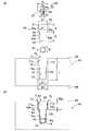
図1は、第一実施形態に係る伝熱板を示した図であって、(a)は、斜視図、(b)は、(a)のX1−X1線断面図である。図2の(a)は、第一実施形態に係る回転ツールの側面図及び伝熱板の分解側面図であり、(b)は、第一実施形態に係る伝熱板の模式配置図である。なお、本説明における上下左右前後は、図1の矢印にしたがう。[First embodiment]
Next, a first embodiment of the present invention will be described in detail with reference to the drawings as appropriate.
Drawing 1 is a figure showing the heat exchanger plate concerning a first embodiment, (a) is a perspective view and (b) is a X1-X1 line sectional view of (a). 2A is a side view of the rotary tool according to the first embodiment and an exploded side view of the heat transfer plate, and FIG. 2B is a schematic arrangement view of the heat transfer plate according to the first embodiment. . Note that the vertical and horizontal directions in this description follow the arrows in FIG.
第一実施形態に係る伝熱板1は、図1及び図2に示すように、表面3に開口する凹溝8を備えたベース部材2と、凹溝8の底部7挿入される熱媒体用管16と、凹溝8に挿入される蓋部材10と、を主に備え、摩擦攪拌接合により形成された塑性化領域W1によって一体形成されている。伝熱板1に係る熱媒体用管16は、図1の(b)に示すように、上方から押し潰されて塑性変形していることを特徴とする。As shown in FIGS. 1 and 2, the heat transfer plate 1 according to the first embodiment is for a
ベース部材2は、図2に示すように、熱媒体用管16に流れる熱媒体の熱を外部に伝達させる役割、あるいは、外部の熱を熱媒体用管16に流れる熱媒体に伝達させる役割を果たすものである。ベース部材2の表面3には、上方に開放する凹溝8が凹設されている。 As shown in FIG. 2, the
凹溝8は、熱媒体用管16が挿入される部分であって、ベース部材2の長手方向に亘って連続して形成されている。凹溝8は、上方が開口した断面視U字状の溝であって、下端に一定の曲率で形成された曲面からなる底部7と、底部7に連続し一定の幅で離間する側壁8a,8bとを有する。 The
凹溝8の幅A(側壁8a、側壁8b間の距離)は、熱媒体用管16の外径B1よりも大きく形成されており、凹溝8の深さCは、熱媒体用管16の外径B1よりも大きく形成されている。また、底部7の曲率は、熱媒体用管16の外周の曲率よりも小さくなるように形成されている。ベース部材2は、例えば、アルミニウム合金(JIS:A6061)で形成されている。 The width A of the concave groove 8 (distance between the
熱媒体用管16は、中空部18に例えば高温液、高温ガスなどの熱媒体を循環させて、ベース部材2及び蓋部材10に熱を伝達させる部材、あるいは中空部18に例えば冷却水、冷却ガスなどの熱媒体を循環させて、ベース部材2及び蓋部材10から熱を伝達される部材である。 The
熱媒体用管16は、図2に示すように、接合工程前は断面視円形を呈するが、図1に示すように、接合工程によって押し潰され、凹溝8及び蓋部材10の形状に沿って塑性変形する。熱媒体用管16の潰れ具合については、後記する。 As shown in FIG. 2, the
なお、熱媒体用管16を流れる熱媒体は特に制限されるものではなく、例えば、熱媒体用管16の中空部18にヒーターを通して、ヒーターから発生する熱をベース部材2及び蓋部材10に伝達させる部材として利用してもよい。 The heat medium flowing through the
また、接合工程前の熱媒体用管16の形状は、本実施形態では円形としたが、特に制限を受けるものではなく、断面視楕円形又は角形等であってもよい。また、熱媒体用管16は、本実施形態においては、銅管を用いたが、他の材料の管を用いてもよい。また、接合工程前において、凹溝8の幅Aと熱媒体用管16の外径B1との寸法は、B1<A<1.4B1の範囲で適宜設定すればよい。 The shape of the
蓋部材10は、図1及び図2に示すように、凹溝8に挿入される部材であって、断面視矩形を呈し、上面11、下面12、側面13a及び側面13bを有する。蓋部材10は、ベース部材2と同種のアルミニウム合金からなる。図2の(b)に示すように、蓋部材10の厚さFは、本実施形態では、厚さFと熱媒体用管16の外径B1との和が、凹溝8の深さCよりも大きくなるように形成されている。 As shown in FIGS. 1 and 2, the
したがって、図2の(b)に示すように、凹溝8に熱媒体用管16及び蓋部材10を挿入すると、蓋部材10の下面12(下部)が、熱媒体用管16に当接するとともに、蓋部材10の上面11は、ベース部材2の表面3よりも突出高さ10aで突出する。
なお、蓋部材10の上面11はベース部材2の表面3から必ずしも突出させる必要はなく、凹溝8に蓋部材10を挿入にした際に、蓋部材10の上面11とベース部材2の表面3とが面一となるように形成してもよい。Therefore, as shown in FIG. 2B, when the
Note that the
また、凹溝8に蓋部材10を挿入すると、蓋部材10の側面13a,13bは、凹溝8の側壁8a,8bと面接触するか又は微細な隙間をあけて対向する。ここで、蓋部材10の一方の側面13aと凹溝8の一方の側壁8aとの突合せ面を以下、突合部V1とする。また、蓋部材10の他方の側面13bと凹溝8の他方の側壁8bとの突合せ面を以下、突合部V2とする。また、突合部V1及び突合部V2を単に突合部Vともいう。また、凹溝8の底部7及び側壁8a,8bと、蓋部材10の下面12とで形成された空間を空間部P1とする。Further, when the
塑性化領域W1は、図1に示すように、突合部V1,V2に摩擦攪拌接合を施した際に、ベース部材2及び蓋部材10の一部が塑性流動して一体化された領域である。ここで、「塑性化領域」とは、回転ツールの摩擦熱によって加熱されて現に塑性化している状態と、回転ツールが通り過ぎて常温に戻った状態の両方を含むこととする。本実施形態では、塑性化領域W1の最大幅Wa(表面3における幅)は、凹溝8の幅A(図2の(a)参照)よりも大きくなるように形成されている。As shown in FIG. 1, when the friction stir welding is performed on the abutting portions V1 and V2 , the plasticizing region W1 is integrated by a part of the
本実施形態では、塑性化領域W1の最深部が、蓋部材10の上面11から蓋部材10の厚さ寸法の約1/3の高さ位置に達するように設定したが、塑性化領域W1の大きさ(深さ)は、蓋部材10の大きさや後記する回転ツールの大きさに基づいて適宜設定すればよく、例えば、塑性化領域W1の最深部が、蓋部材10の上面11から蓋部材10の厚さ寸法の約2/3〜1/3の位置に達するように設定すればよい。In the present embodiment, the deepest part of the plasticized region W1 is, has been set from the
次に、伝熱板1の製造方法について、図3を用いて説明する。図3は、第一実施形態に係る伝熱板の製造方法を示した側断面図であって、(a)は、熱媒体用管を挿入した熱媒体用管挿入工程を示し、(b)は、蓋部材挿入工程を示し、(c)は、接合工程を示す。 Next, the manufacturing method of the heat exchanger plate 1 is demonstrated using FIG. FIG. 3 is a side sectional view showing a method of manufacturing a heat transfer plate according to the first embodiment, wherein (a) shows a heat medium tube insertion step in which a heat medium tube is inserted, and (b) Shows a lid member insertion step, and (c) shows a joining step.
第一実施形態に係る伝熱板の製造方法は、ベース部材2を形成する準備工程と、ベース部材2に形成された凹溝8に熱媒体用管16を挿入する熱媒体用管挿入工程と、凹溝8に蓋部材10を挿入する蓋部材挿入工程と、突合部Vに沿って接合用回転ツール20を移動させて摩擦攪拌接合を施す接合工程とを含むものである。 The heat transfer plate manufacturing method according to the first embodiment includes a preparation process for forming the
まず、接合工程の摩擦攪拌で用いる回転ツールについて図2の(a)を用いて説明する。本実施形態で用いる接合用回転ツール20は、例えば、工具鋼からなり、円柱形のショルダ部22と、その下面24の中心部から同心軸で垂下する攪拌ピン26とを有する。攪拌ピン26は、先端に向けて幅狭となるテーパ状を呈し、長さLAで形成されている。なお、攪拌ピン26の周面には、その軸方向に沿って図示しない複数の小溝や径方向に沿ったネジ溝が形成されていてもよい。First, a rotating tool used for friction stirring in the joining process will be described with reference to FIG. The joining
本実施形態では、ショルダ部22の外径X1は、凹溝8の幅A以上の大きさに形成されている。これにより、蓋部材10(凹溝8)に沿って接合用回転ツール20を一回通り移動させることで、突合部V1,V2に対して同時に摩擦攪拌を行うことができる。In this embodiment, the outer diameter X1 of the
なお、本実施形態では、接合用回転ツール20を前記したように設定したが、例えば、攪拌ピン26の基端部(最大外径X2)を、凹溝8の幅A以上に設定してもよい。また、例えば、攪拌ピン26の先端部(最小外径X3)を、凹溝8の幅A以上に設定してもよい。このように、幅Aに対して、接合用回転ツール20の大きさを大きく設定することで、突合部V1,V2を一回の移動でより確実に摩擦攪拌を行うことができる。In the present embodiment, the
(準備工程)
まず、図2の(a)を参照するように、例えばエンドミル加工により、厚板部材に凹溝8を形成する。これにより、表面3に開口する凹溝8を備えたベース部材2が形成される。凹溝8は、下部に曲面からなる底部7を備えており、底部7から一定の幅で上方に向けて開口されている。
なお、ベース部材2を本実施形態においては切削加工により形成したが、アルミニウム合金の押出形材を用いてもよい。(Preparation process)
First, as shown in FIG. 2A, the
Although the
(熱媒体用管挿入工程)
次に、図3の(a)に示すように、凹溝8に熱媒体用管16を挿入する。熱媒体用管16の下端は、凹溝8の底部7と接触する。(Heat medium tube insertion process)
Next, as shown in FIG. 3A, the
(蓋部材挿入工程)
次に、図3の(b)に示すように、ベース部材2の凹溝8内に、蓋部材10を挿入する。この際、蓋部材10の下面12が熱媒体用管16の上端に当接すると共に、蓋部材10の上面11が、ベース部材2の表面3から突出する。また、凹溝8の側壁8a,8bと蓋部材10の側面13a,13bによって突合部V1,V2が形成される。(Cover member insertion process)
Next, as shown in FIG. 3B, the
(接合工程)
次に、図3の(c)に示すように、突合部V(突合部V1,V2)に対して接合用回転ツール20を用いて摩擦攪拌を行う。即ち、接合用回転ツール20の中心と、凹溝8の幅方向の中心とを合わせた後、接合用回転ツール20のショルダ部22の下面24をベース部材2の表面3に所定の深さで押し込み、突合部Vに沿って相対移動させる。本実施形態では、接合用回転ツール20の回転数は、例えば50〜1500rpm、送り速度は、0.05〜2m/分であり、接合用回転ツール20の軸方向に加える押し込み力は、1kN〜20kNに設定した。(Joining process)
Next, as shown in (c) of FIG. 3, friction agitation is performed on the abutting portion V (the abutting portions V1 and V2 ) using the joining
接合工程によれば、接合用回転ツール20の押圧力が蓋部材10を介して熱媒体用管16に伝達するため、熱媒体用管16は、凹溝8及び蓋部材10の下面12の形状に沿って塑性変形する。 According to the joining step, the pressing force of the joining
図1の(b)に示すように、接合工程によってベース部材2の表面3に塑性化領域W1が形成される。本実施形態では、塑性化領域W1の最深部が、蓋部材10の上面11から蓋部材10の厚さ寸法の約1/3の高さ位置に達するように攪拌ピン26の長さ及び接合用回転ツール20の押込み量等を設定している。また、図3の(c)に示すように、突合部V1,V2における塑性化領域W1の深さWbは、蓋部材10の厚さの1/5程度となるように設定している。突合部V1,V2における塑性化領域W1の深さWbを大きく設定することにより、ベース部材2と蓋部材10との接合力を高めることができる。As shown in FIG. 1 (b), plasticized region W1 is formed on the surface 3 of the
また、本実施形態に係る接合工程では、接合工程後の熱媒体用管16の高さB2が、接合工程前の熱媒体用管16の高さB1の約70%となるように形成している。接合工程後の熱媒体用管16の高さB2は、接合工程前の熱媒体用管16の高さB1の70%以上となることが好ましい。また、接合工程後の熱媒体用管16の高さB2は、接合工程前の熱媒体用管16の高さB1の80%以上となることがより好ましい。また、熱媒体用管16の潰れ具合を示す据込率(B1−B2/B1)×100の値は、20%〜30%となるように設定するのが好ましい。 Further, in the joining process according to the present embodiment, the
なお、塑性化領域W1の大きさ(深さ)、接合用回転ツール20の形状や回転数又は押込み量等はあくまで例示であって、限定されるものではなく、ベース部材2及び蓋部材10の材料等を考慮して適宜設定すればよい。例えば、本実施形態では、接合用回転ツール20の攪拌ピン26の長さLAは、ショルダ部22の外径X1の約1/2となるように形成しているが、攪拌ピン26の長さLAをショルダ部22の外径X1の1/2よりも小さく形成してもよい。これにより、接合用回転ツール20の押圧力の伝達効率を高めることができる。The size of the plasticized region W1 (depth), shape and number of revolutions or the pushing amount of the joining
以上のように本実施形態に係る伝熱板の製造方法の接合工程では、接合用回転ツール20のショルダ部22の外径X1が凹溝8の幅Aよりも大きいため、熱媒体用管16の上方に接合用回転ツール20が位置した状態で摩擦攪拌を行うことができる。これにより、凹溝8と蓋部材10の下面12との形状に沿って熱媒体用管16を効率よく塑性変形させることができ、凹溝8と熱媒体用管16との密着性を高めることができる。
また、本実施形態では、熱媒体用管16の中心を通る鉛直線上に、蓋部材10及び接合用回転ツール20の中心が位置するため、接合用回転ツール20の押圧力をより効率よく熱媒体用管16に伝達することができるとともに、熱媒体用管16をバランスよく塑性変形させることができる。In the bonding step of the manufacturing method of the heat transfer plate according to the present embodiment as described above, since the outer diameter X1 of the
In the present embodiment, since the centers of the
ここで、図4の(a)は、蓋部材挿入工程を示した模式断面図、(b)は、接合工程における押圧超過状態を示した模式断面図、(c)は、第一実施形態の完成時を示した模式断面図である。
図4の(a)に示すように、蓋部材挿入工程時においては、凹溝8の底部7、側壁8a、側壁8b及び蓋部材10の下面12で囲まれた領域の内周長N2(太線部分の長さ)は、熱媒体用管16の外周長N1よりも大きく形成されている。Here, (a) of FIG. 4 is a schematic cross-sectional view showing the lid member inserting step, (b) is a schematic cross-sectional view showing an over-pressed state in the joining step, and (c) is the first embodiment. It is the schematic cross section which showed the time of completion.
As shown in FIG. 4A, at the time of the lid member insertion step, the inner peripheral length N2 (bold line) of the region surrounded by the
仮に、図4の(b)に示すように、接合工程において蓋部材10の押し込み量が超過すると、凹溝8及び蓋部材10の下面12で囲まれた領域の鉛直断面の内周長N2(太線部分の長さ)が、熱媒体用管16の外周長N1よりも小さくなる。また、押し込み超過時における接合工程後の熱媒体用管16の高さB3は、高さB2(図3の(c)参照)よりも小さくなる。
これにより、熱媒体用管16が内側に凹となるように変形し、熱媒体用管16と蓋部材10の下面12との間に空間部P2が形成される可能性がある。このように、熱媒体用管16と、凹溝8及び蓋部材10の下面12との間に空隙があると、伝熱板1の伝熱効率が低下するため、好ましくない。As shown in FIG. 4B, when the pushing amount of the
As a result, the
一方、図4の(c)に示すように、本実施形態の完成時においては、内周長N2(太線部分の長さ)と熱媒体用管16の外周長N1とが略同等に形成されている。即ち、熱媒体用管16の外周長N1と、凹溝8及び蓋部材10の下面12で囲まれた領域の内周長N2とが近似するほど、空間部P1(図4の(a)参照)が小さくなるため、伝熱板1の伝熱効率を高めることができる。 On the other hand, as shown in FIG. 4C, when the present embodiment is completed, the inner peripheral length N2 (the length of the thick line portion) and the outer peripheral length N1 of the
また、本実施形態では、接合用回転ツール20のショルダ部22の外径X1が、凹溝8の幅Aよりも大きいため、一回の接合用回転ツール20の移動で蓋部材10とベース部材2との一対の突合部V1,V2を同時に摩擦攪拌できる。これにより、製造工程の作業手間を少なくすることができる。また、蓋部材10とベース部材2とを摩擦攪拌で接合するため、従来と比べて接合力を高めることができる。Further, in this embodiment, the outer diameter X1 of the
なお、本実施形態の製造工程はあくまで例示であって、他の工程であっても構わない。例えば、図3の(b)を参照するように、蓋部材挿入工程の前に、熱媒体用管16と蓋部材10の下面12との間に形成される空間部P1に、熱伝導性物質を充填する充填工程を行ってもよい。熱伝導性物質を充填することで、完成後の空隙を小さくして、伝熱効率を高めることができる。 In addition, the manufacturing process of this embodiment is an illustration to the last, Comprising: You may be another process. For example, as shown in FIG. 3B, the heat conductive substance is formed in the space P1 formed between the
なお、熱伝導性物質は、例えば、公知の金属粉末の低融点ろう材を用いればよいが、伝熱効率を高める材料であれば特に制限はなく、金属粉末、金属粉末ペースト及び金属シートなどであってもよい。 The heat conductive material may be, for example, a known low melting point brazing material of metal powder, but is not particularly limited as long as it is a material that enhances heat transfer efficiency, such as metal powder, metal powder paste, and metal sheet. May be.
[第二実施形態]
次に、本発明の第二実施形態に係る伝熱板及び伝熱板の製造方法について説明する。
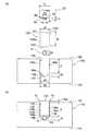
図5の(a)は、第二実施形態に係る回転ツールの側面図及び伝熱板の分解側面図であり、(b)は、第二実施形態に係る模式配置図である。図6は、第二実施形態に係る伝熱板の製造方法を示した側断面図であって、(a)は、接合工程、(b)は、完成図を示す。図7は、第二実施形態の完成時を示した模式断面図である。[Second Embodiment]
Next, a heat transfer plate and a method for manufacturing the heat transfer plate according to the second embodiment of the present invention will be described.
FIG. 5A is a side view of the rotary tool according to the second embodiment and an exploded side view of the heat transfer plate, and FIG. 5B is a schematic layout view according to the second embodiment. FIG. 6 is a side sectional view showing a method for manufacturing a heat transfer plate according to the second embodiment, where (a) shows a joining step and (b) shows a completed drawing. FIG. 7 is a schematic cross-sectional view showing the completed second embodiment.
第二実施形態に係る伝熱板91及び伝熱板の製造方法は、図5及び図6に示すように、蓋部材60及び凹溝70の幅長が、それぞれ二種類備えられていることを特徴とする。
まず、伝熱板91(図6の(b)参照)の構成について説明する。第一実施形態と共通する部分は説明を省略する。As shown in FIGS. 5 and 6, the
First, the configuration of the heat transfer plate 91 (see FIG. 6B) will be described. Descriptions of parts common to the first embodiment are omitted.
図5の(a)に示すように、ベース部材82の表面83には、凹溝70が凹設されている。凹溝70は、後記する蓋部材60が挿入される部分である。凹溝70は、幅広に形成された幅広凹溝部71と、幅広凹溝部71の底面72に形成され幅広凹溝部71よりも幅狭に形成された幅狭凹溝部73とを有する。 As shown in FIG. 5A, a
幅広凹溝部71は、断面視矩形を呈し、底面72と、底面72から垂直に立設された側壁71a,71bとを有する。幅狭凹溝部73は、断面視U字状を呈し、一定の曲率で形成された曲面からなる底部74と、底部74に連続し一定の幅で離間する側壁73a,73bとを有する。 The wide
幅狭凹溝部73の幅e1(側壁73a,73b間の距離)は、熱媒体用管16の外径B1よりも大きく形成されており、幅狭凹溝部73の深さcは、熱媒体用管16の外径B1よりも大きく形成されている。また、底部74の曲率は、熱媒体用管16の外周の曲率よりも小さくなるように形成されている。ベース部材82は、例えば、アルミニウム合金(JIS:A6061)で形成されている。 The width e1 (distance between the
熱媒体用管16は、図5に示すように、接合工程前は断面視円形を呈するが、図6に示すように、接合工程によって押し潰されて、幅狭凹溝部73及び蓋部材60の下面65形状に沿って塑性変形する。熱媒体用管16の潰れ具合については後記する。 As shown in FIG. 5, the
蓋部材60は、図5に示すように、凹溝70に挿入される部材であって、断面視略T字状を呈し、幅広に形成された幅広部61と、幅広部61よりも幅狭に形成された幅狭部62とを有する。蓋部材60は、ベース部材82と同種のアルミニウム合金で形成されている。 As shown in FIG. 5, the
幅広部61は、断面視矩形を呈し、上面63、側面63a,63b及び下面64を備えている。幅広部61の幅G1は、幅広凹溝部71の幅E1と略同等に形成されており、幅広部61の厚さf1は、幅広凹溝部71の深さjと略同等に形成されている。 The
幅狭部62は、幅広部61の下面64から下方に延設されており、側面62a,62b及び下面65を備えている。幅狭部62の幅g1は、幅狭凹溝部73の幅e1と略同等に形成されている。幅狭部62の厚さf2は、厚さf2と熱媒体用管16の外径B1との和が、幅狭凹溝部73の深さcよりも大きくなるように形成されている。下面65は、下側に向けて凹状となる曲面からなる。下面65の曲率は、熱媒体用管16の外周の曲率よりも小さくなるように形成されている。 The
したがって、図5の(b)に示すように、凹溝70に熱媒体用管16及び蓋部材60を挿入すると、幅狭部62の下面65が熱媒体用管16に当接するともに、蓋部材60の上面63は、ベース部材82の表面83よりも突出高さ60aで突出する。また、幅広凹溝部71の底面72と、蓋部材60の幅広部61の下面64が、離間距離L1で離間する。突出高さ60aと離間距離L1は、略同等の長さとなる。 Therefore, as shown in FIG. 5B, when the
また、凹溝70に蓋部材60を挿入すると、蓋部材60の幅広部61の側面63a,63bは、幅広凹溝部71の側壁71a,71bと面接触するか又は微細な隙間をあけて対向する。ここで、蓋部材60の幅広部61の一方の側面63aと幅広凹溝部71の一方の側壁71aとの突合せ面を以下、突合部V3とする。また、蓋部材60の他方の側面63bと幅広凹溝部71の他方の側壁71bとの突合せ面を以下、突合部V4とする。また、突合部V3及び突合部V4を単に突合部Vともいう。また、幅狭凹溝部73の底部74及び側壁73a,73bと、蓋部材60の下面65とで形成された空間を空間部P3とする。Further, when the
塑性化領域W2は、図6の(b)に示すように、突合部V3,V4に摩擦攪拌接合を施した際に、ベース部材82及び蓋部材60の一部が塑性流動して一体化された領域である。本実施形態では、塑性化領域W2の最大幅Wa(表面3における幅)は、幅広凹溝部71の幅E1(図5の(a)参照)よりも大きくなるように形成されている。Plasticized region W2, as shown in (b) of FIG. 6, when subjected to friction stir welding the butting portion V3, V4, part of the
次に、伝熱板91の製造方法について、図6を用いて説明する。
第二実施形態に係る伝熱板の製造方法は、ベース部材82を形成する準備工程と、ベース部材82に形成された凹溝70に熱媒体用管16を挿入する熱媒体用管挿入工程と、凹溝70に蓋部材60を挿入する蓋部材挿入工程と、突合部Vに沿って接合用回転ツール20を移動させて摩擦攪拌接合を施す接合工程とを含むものである。なお、準備工程は第一実施形態と略同等であるため省略する。Next, the manufacturing method of the heat-
The heat transfer plate manufacturing method according to the second embodiment includes a preparation process for forming the
(熱媒体用管挿入工程)
熱媒体用管挿入工程では、図5の(a)及び(b)に示すように、凹溝70の幅狭凹溝部73に熱媒体用管16を挿入する。熱媒体用管16の下端は、幅狭凹溝部73の底部74と接触する。(Heat medium tube insertion process)
In the heat medium tube insertion step, the
(蓋部材挿入工程)
次に、図5の(b)に示すように、ベース部材82の凹溝70内に、蓋部材60を挿入する。この際、蓋部材60の幅狭部62の下面65が熱媒体用管16の上端に当接すると共に、蓋部材60の上面63が、ベース部材82の表面83から突出する。(Cover member insertion process)
Next, as shown in FIG. 5B, the
(接合工程)
次に、図6の(b)に示すように、突合部V(突合部V3,V4)に対して接合用回転ツール20を用いて摩擦攪拌を行う。即ち、接合用回転ツール20の中心と、凹溝70の幅方向の中心とを合わせた後、接合用回転ツール20のショルダ部22の下面24をベース部材82の表面83に所定の深さで押し込み、突合部Vに沿って相対移動させる。(Joining process)
Next, as shown in FIG. 6B, friction stir is performed on the abutting portion V (abutting portions V3 , V4 ) using the joining
接合工程によれば、接合用回転ツール20の押圧力が蓋部材60を介して熱媒体用管16に伝達するため、熱媒体用管16は、幅狭凹溝部73及び蓋部材60の下面65の形状に沿って塑性変形する。接合工程後の熱媒体用管16の鉛直方向高さB4は、接合工程前の熱媒体用管16の外径B1の約80%となるように押し潰される。 According to the joining step, the pressing force of the joining
以上のように本実施形態に係る伝熱板の製造方法では、接合用回転ツール20のショルダ部22の外径X1が凹溝70の幅E1よりも大きいため、熱媒体用管16の上方に接合用回転ツール20が位置した状態で摩擦攪拌を行うことができる。これにより、幅狭凹溝部73と蓋部材60の下面65との形状に沿って熱媒体用管16を効率よく塑性変形させることができ、凹溝70と熱媒体用管16との密着性を高めることができる。
また、本実施形態では、熱媒体用管16の中心を通る鉛直線上に、蓋部材60及び接合用回転ツール20の中心が位置するため、接合用回転ツール20の押圧力をより効率よく熱媒体用管16に伝達することができるとともに、熱媒体用管16をバランスよく塑性変形させることができる。In the method of manufacturing the heat transfer plate according to the present embodiment as described above, since the outer diameter X1 of the
In the present embodiment, since the centers of the
また、本実施形態では、蓋部材60の下面65(下部)を曲面としているため、断面視円形を呈する熱媒体用管16が、下面65に沿って変形しやすく、空間部P3を効率よく小さくすることができる。 Further, in the present embodiment, since the lower surface 65 (lower part) of the
即ち、図7に示すように、本実施形態の完成時においては、幅狭凹溝部73と、蓋部材60の下面65とで囲まれた領域の内周長N2(図7の太線部分)と、熱媒体用管16の外周長N1とが略同等に形成されている。これにより、熱媒体用管16とベース部材82との密接度を高めることができる。 That is, as shown in FIG. 7, when the present embodiment is completed, the inner peripheral length N <b> 2 (the thick line portion in FIG. 7) of the region surrounded by the narrow
また、本実施形態では、凹溝70が幅狭凹溝部73と幅広凹溝部71とを有するとともに、蓋部材60も幅狭部62と幅広部61とを有する。したがって、図6の(a)に示すように、接合工程において蓋部材60の上方から接合用回転ツール20を押圧すると、蓋部材60の幅広部61の下面64が、幅広凹溝部71の底面72に当接する。これにより、蓋部材60が底面72よりも下に押し込まれることがないため、熱媒体用管16が過剰に塑性変形することを防止することができる。つまり、幅広凹溝部71の深さjや蓋部材60の幅広部61の厚さf1を適宜設定することで、熱媒体用管16の据込率を容易に設定することができる。 In the present embodiment, the
また、本実施形態では、接合用回転ツール20のショルダ部22の外径X1が、幅広凹溝部71の幅E1よりも大きいため、一回の接合用回転ツール20の移動で蓋部材60とベース部材82との一対の突合部V3,V4を同時に摩擦攪拌できる。これにより、製造工程の作業手間を少なくすることができる。また、蓋部材60とベース部材82とを摩擦攪拌で接合するため、従来と比べて接合力を高めることができる。Further, in the present embodiment, the outer diameter X1 of the
[第三実施形態]
次に、本発明の第三実施形態に係る伝熱板及び伝熱板の製造方法ついて説明する。
図8の(a)は、第三実施形態に係る回転ツールの側面図及び伝熱板の分解側面図であり、(b)は、第三実施形態に係る模式配置図である。図9は、第三実施形態に係る伝熱板の製造方法を示した側断面図であって、(a)は、熱媒体用管を挿入した熱媒体用管挿入工程を示し、(b)は、蓋部材挿入工程を示し、(c)は、接合工程を示し、(d)は、完成図を示す。図10は、第三実施形態の完成時を示した模式断面図である。[Third embodiment]
Next, a heat transfer plate and a method for manufacturing the heat transfer plate according to the third embodiment of the present invention will be described.
FIG. 8A is a side view of the rotary tool according to the third embodiment and an exploded side view of the heat transfer plate, and FIG. 8B is a schematic layout view according to the third embodiment. FIG. 9 is a side sectional view showing a method of manufacturing a heat transfer plate according to the third embodiment, wherein (a) shows a heat medium tube insertion step in which a heat medium tube is inserted, and (b) Shows a lid member insertion step, (c) shows a joining step, and (d) shows a completed drawing. FIG. 10 is a schematic cross-sectional view showing a completed state of the third embodiment.
第三実施形態に係る伝熱板は、図8の(a)及び(b)に示すように、接合工程前の熱媒体用管16の外径B1が、凹溝148の深さc2よりも大きいことを特徴とする。まず、図9の(d)に示す伝熱板151の構成について説明する。 In the heat transfer plate according to the third embodiment, as shown in FIGS. 8A and 8B, the outer diameter B1 of the
図8の(a)に示すように、ベース部材142の表面143には、蓋溝146が凹設されており、蓋溝146の底面146aの中央には、蓋溝146よりも幅狭の凹溝148が凹設されている。蓋溝146は、蓋部材130が配置される部分であって、ベース部材142の長手方向に亘って連続して形成されている。蓋溝146は、断面視矩形を呈し、蓋溝146の底面146aから垂直に立ち上がる側壁145a,145bを備えている。蓋溝146の幅E2は、後記する蓋部材130の幅g2と略同等に形成されており、蓋溝146の深さj2は、蓋部材130の深さf3と略同等に形成されている。 As shown in FIG. 8A, a
凹溝148は、熱媒体用管16が挿入される部分であって、ベース部材142の長手方向に亘って連続して形成されている。凹溝148は、上方が開口した断面視U字状の溝であって、下端には一定の曲率からなる底部147が形成されている。凹溝148の開口部の幅A2は、熱媒体用管16の外径B1よりも大きく形成されている。 The
熱媒体用管16は、図8の(a)に示すように、接合工程前は断面視円形を呈するが、図9の(c)に示すように、接合工程によって押し潰されて凹溝148及び蓋部材130の下面132の形状に沿って塑性変形する。熱媒体用管16の潰れ具合については後記する。 As shown in FIG. 8A, the
蓋部材130は、図8の(a)に示すように、蓋溝146に挿入される部材であって、断面視矩形を呈し、上面131、下面132、側面133a及び側面133bを有する。蓋部材130は、ベース部材142と同種のアルミニウム合金からなる。蓋部材130の厚さf3は、本実施形態では、蓋溝146の深さj2と同等に形成されている。 As shown in FIG. 8A, the
したがって、図8の(b)に示すように、凹溝148に熱媒体用管16を挿入し、蓋溝146に蓋部材130を挿入すると、蓋部材130の下面132が熱媒体用管16に当接するとともに、蓋部材130の上面131は、ベース部材142の表面143よりも突出高さ130aで突出する。
なお、蓋部材130の上面131はベース部材142の表面143から必ずしも突出させる必要はなく、蓋溝146に蓋部材130を挿入した際に、蓋部材130の上面131とベース部材142の表面143とが面一になるように形成してもよい。Therefore, as shown in FIG. 8B, when the
Note that the
また、蓋溝146に蓋部材130を挿入すると、蓋部材130の側面133a,133bは、蓋溝146の側壁145a,145bと面接触するか又は微細な隙間をあけて対向する。ここで、蓋部材130の一方の側面133aと蓋溝146の側壁145aとの突合せ面を以下、突合部V5とする。また、蓋部材130の他方の側面133bと蓋溝146の側壁145bとの突合せ面を以下、突合部V6とする。また、突合部V5及び突合部V6を単に突合部Vともいう。また、凹溝148、熱媒体用管16、蓋溝146及び蓋部材130の下面132で形成された空間を空間部P4とする。When the
塑性化領域W3は、図9の(d)に示すように、突合部V5,V6に摩擦攪拌接合を施した際に、ベース部材142及び蓋部材130の一部が塑性流動して一体化された領域である。本実施形態では、塑性化領域W3の最大幅Wa(表面143における幅)は、蓋溝146の幅E2(図8の(a)参照)よりも大きくなるように形成されている。Plasticized region W3 being as shown in (d) of FIG. 9, when subjected to friction stir welding the butting portion V5, V6, a portion of the
次に、伝熱板151の製造方法について、図3を用いて説明する。
第三実施形態に係る伝熱板の製造方法は、ベース部材142を形成する準備工程と、ベース部材142に形成された凹溝148に熱媒体用管16を挿入する熱媒体用管挿入工程と、蓋溝146に蓋部材130を挿入する蓋部材挿入工程と、突合部Vに沿って接合用回転ツール20を移動させて摩擦攪拌接合を施す接合工程とを含むものである。Next, the manufacturing method of the heat-
The heat transfer plate manufacturing method according to the third embodiment includes a preparation process for forming the
(準備工程)
まず、図9の(a)を参照するように、例えばエンドミル加工により、厚板部材に蓋溝146を形成した後、蓋溝146の底面146aの中央に凹溝148を形成する。
なお、ベース部材142を本実施形態においては切削加工により形成したが、アルミニウム合金の押出形材を用いてもよい。(Preparation process)
First, as shown in FIG. 9A, after forming the
Although the
(熱媒体用管挿入工程)
次に、図9の(a)に示すように、凹溝148に熱媒体用管16を挿入する。熱媒体用管16の下端は、凹溝148の底部147と接触する。(Heat medium tube insertion process)
Next, as shown in FIG. 9A, the
(蓋部材挿入工程)
次に、図9の(b)に示すように、ベース部材142の蓋溝146に、蓋部材130を挿入する。この際、蓋部材130の下面132が熱媒体用管16の上端に当接すると共に、蓋部材130の上面131が、ベース部材142の表面143から突出する。また、蓋溝146の側壁145a,145bと蓋部材130の側面133a,133bによって突合部V5,V6が形成される。(Cover member insertion process)
Next, as shown in FIG. 9B, the
(接合工程)
次に、図9の(c)に示すように、突合部V(突合部V1,V2)に対して接合用回転ツール20を用いて摩擦攪拌を行う。即ち、接合用回転ツール20の中心と、蓋溝146の幅方向の中心とを合わせた後、接合用回転ツール20のショルダ部22の下面24をベース部材142の表面143に所定の深さで押し込み、突合部Vに沿って相対移動させる。なお、本実施形態に係る接合用回転ツール20の攪拌ピン26の長さLBは、ショルダ部22の外径X1の約1/5に形成されている。ショルダ部22の外径X1に対して攪拌ピン26の長さLBを小さく形成することで、接合用回転ツール20の押圧力を蓋部材130に効率よく伝達させることができる。(Joining process)
Next, as shown in (c) of FIG. 9, friction agitation is performed on the abutting portion V (the abutting portions V1 and V2 ) using the joining
接合工程によれば、接合用回転ツール20の押圧力が蓋部材130を介して熱媒体用管16に伝達するため、熱媒体用管16は、凹溝148及び蓋部材130の下面132の形状に沿って塑性変形する。接合工程後の熱媒体用管16の鉛直方向高さB5は、接合工程前の熱媒体用管16の外径B1の約70%となるように押し潰される。 According to the joining process, the pressing force of the joining
以上のように本実施形態に係る伝熱板の製造方法の接合工程では、接合用回転ツール20のショルダ部22の外径X1が蓋溝146の幅E2よりも大きいため、熱媒体用管16の上方に接合用回転ツール20が位置した状態で摩擦攪拌を行うことができる。これにより、凹溝148と蓋部材130の下面132との形状に沿って熱媒体用管16を効率よく塑性変形させることができ、凹溝148と熱媒体用管16との密着性を高めることができる。
また、本実施形態では、熱媒体用管16の中心を通る鉛直線上に、蓋部材130及び接合用回転ツール20の中心が位置するため、接合用回転ツール20の押圧力をより効率よく熱媒体用管16に伝達することができるとともに、熱媒体用管16をバランスよく塑性変形させることができる。In the bonding step of the manufacturing method of the heat transfer plate according to the present embodiment as described above, since the outer diameter X1 of the
In the present embodiment, since the centers of the
即ち、図10に示すように、本実施形態の完成時においては、凹溝148と、蓋部材130の下面132とで囲まれた領域の内周長N2(図10の太線部分)と、熱媒体用管16の外周長N1とが略同等に形成されている。これにより、熱媒体用管16とベース部材142との密接度を高めることができる。 That is, as shown in FIG. 10, when the present embodiment is completed, the inner peripheral length N2 (the thick line portion in FIG. 10) of the region surrounded by the
また、本実施形態では、接合工程の際に、蓋部材130の下面132が、蓋溝146の底面146aに当接する。これにより、蓋部材130が蓋溝146の底面146aよりも下方に押し込まれることがないため、熱媒体用管16が過剰に潰れることを防止することができる。つまり、蓋溝146の深さj2及び蓋部材130の厚さf3、凹溝148の深さc2及び熱媒体用管16の外径B1等を適宜設定することで、熱媒体用管16の据込率を容易に設定することができる。 In the present embodiment, the
また、本実施形態では、接合用回転ツール20のショルダ部22の外径X1が、蓋溝146の幅E2よりも大きいため、一回の接合用回転ツール20の移動で蓋部材130とベース部材142との一対の突合部V5,V6を同時に摩擦攪拌できる。これにより、製造工程の作業手間を少なくすることができる。また、蓋部材130とベース部材142とを摩擦攪拌で接合するため、従来と比べて接合力を高めることができる。Further, in this embodiment, the outer diameter X1 of the
[第四実施形態]
次に、第四実施形態に係る伝熱板について説明する。図11の(a)は、第四実施形態に係る伝熱板を示した分解側断面図であり、(b)は、第四実施形態に係る伝熱板を示した側断面図である。
図11に示す第四実施形態に係る伝熱板201は、第一実施形態に係る伝熱板1(図1参照)と略同等の構造を内包し、蓋部材10の上方にさらに上蓋部材210を配置して、摩擦攪拌接合を施して接合した点で第一実施形態と相違する。
なお、前記した伝熱板1と同等の構造を以下、下蓋部Mともいう。また、第一実施形態に係る伝熱板1と重複する部材については、同等の符号を付し、重複する説明は省略する。[Fourth embodiment]
Next, a heat transfer plate according to the fourth embodiment will be described. FIG. 11A is an exploded side sectional view showing the heat transfer plate according to the fourth embodiment, and FIG. 11B is a side sectional view showing the heat transfer plate according to the fourth embodiment.
A
In addition, the structure equivalent to the above-described heat transfer plate 1 is also referred to as a lower lid portion M below. Moreover, about the member which overlaps with the heat exchanger plate 1 which concerns on 1st embodiment, an equivalent code | symbol is attached | subjected and the overlapping description is abbreviate | omitted.
伝熱板201は、図11の(a)及び(b)に示すように、ベース部材202と、凹溝8に挿入された熱媒体用管16と、蓋部材10と、蓋部材10の表面側に配置された上蓋部材210とを有し、塑性化領域W1、塑性化領域W4,W5で摩擦攪拌接合により一体化されている。As shown in FIGS. 11A and 11B, the
ベース部材202は、図11の(a)に示すように、例えばアルミニウム合金からなり、ベース部材202の表面203に、長手方向に亘って形成された上蓋溝206と、上蓋溝206の底面206cに長手方向に亘って連続して形成された凹溝8とを有する。上蓋溝206は、断面視矩形を呈し、底面206cから垂直に立ち上がる側壁206a,206bを備えている。上蓋溝206の幅は、凹溝8の幅よりも大きく形成されている。 As shown in FIG. 11A, the
図11の(a)に示すように、ベース部材202の下部に形成された凹溝8には、熱媒体用管16が挿入されており、蓋部材10によって閉塞され、摩擦攪拌接合により塑性化領域W1で接合されている。即ち、ベース部材202の内部に形成された下蓋部Mは、第一実施形態に係る伝熱板1と略同等に形成されている。As shown in FIG. 11A, the
なお、上蓋溝206の底面206cには、摩擦攪拌接合を行ったことにより、段差(溝)やバリが発生している可能性がある。したがって、例えば塑性化領域W1の表面を基準に、上蓋溝206の底面206cに面削加工を施して平滑に形成することが好ましい。これにより、上蓋部材210の下面212と、面削後の上蓋溝206の底面206cとを隙間なく配置することができる。Note that a step (groove) or a burr may be generated on the
上蓋部材210は、図11の(a)に示すように、例えば、アルミニウム合金からなり、上蓋溝206の断面と略同じ矩形断面を形成し、下面212から垂直に形成された側面213a及び側面213bとを有する。上蓋部材210は、上蓋溝206に挿入される。即ち、上蓋部材210の側面213a,213bは、上蓋溝206の側壁206a,206bと面接触されるか又は微細な隙間をあけて配置されている。ここで、図11の(b)に示すように、一方の側面213aと一方の側壁206aとの突合せ面を以下、上側突合部V7とする。また、他方の側面213bと他方の側壁206bとの突合せ面を以下、上側突合部V8とする。上側突合部V7,V8は、摩擦攪拌接合により、塑性化領域W4,W5で一体化されている。As shown in FIG. 11A, the
伝熱板201の製造方法は、伝熱板1と同等の製造方法により、ベース部材202の下部に下蓋部Mを形成した後、上蓋溝206の底面206cを面削する面削工程と、上蓋部材210を配置する上蓋部材挿入工程と、上側突合部V7,V8に沿って摩擦攪拌接合を施す上蓋部材接合工程を含むものである。The method of manufacturing the
(面削工程)
面削工程では、上蓋溝206の底面206cに形成された段差(溝)やバリを切削除去して、底面206cを平滑にする。(Chamfering process)
In the chamfering step, the step (groove) and burrs formed on the
(上蓋部材挿入工程)
上蓋部材挿入工程では、面削工程をした後、上蓋溝206の底面に上蓋部材210を配置する。面削工程を行ったことにより、上蓋部材210の下面212と、上蓋溝206の底面とを隙間なく配置することができる。(Upper cover member insertion process)
In the upper lid member inserting step, the
(上蓋部材接合工程)
上蓋部材接合工程は、上側突合部V7,V8に沿って接合用回転ツール(図示省略)を移動させて摩擦攪拌接合を施す。上蓋部材接合工程における接合用回転ツールの押し込み量は、当該接合用回転ツールの攪拌ピンの長さ及び上蓋部材210の厚さを考慮して適宜設定すればよい。上蓋部材接合工程では、第一実施形態で使用する接合用回転ツール20を用いてもよい。(Top cover member joining process)
In the upper lid member joining step, the joining rotary tool (not shown) is moved along the upper abutting portions V7 and V8 to perform friction stir welding. The pushing amount of the joining rotary tool in the upper lid member joining step may be appropriately set in consideration of the length of the stirring pin of the joining rotary tool and the thickness of the
第四実施形態に係る伝熱板201によれば、下蓋部Mの上方にさらに上蓋部材210を配置して、摩擦攪拌接合を施すことにより、より深い位置に熱媒体用管16を配置させることができる。 According to the
なお、第四実施形態においては、上蓋部材210の両側面を摩擦攪拌して二条の塑性化領域W4,W5が形成されるようにしたが、これに限定されるものではない。例えば、上蓋溝206の幅を、接合用回転ツール20(図2の(a)参照)のショルダ部22の外径X1よりも小さく形成して、接合用回転ツール20を用いて上蓋部材210を一条の摩擦攪拌で行ってもよい。これにより、接合工程を削減することができる。In the fourth embodiment, two side surfaces of the
[第五実施形態]
次に、第五実施形態に係る伝熱板について説明する。図12の(a)は、第五実施形態に係る伝熱板を示した分解側断面図であり、(b)は、第五実施形態に係る伝熱板を示した側断面図である。
図12に示す第五実施形態に係る伝熱板301は、第三実施形態に係る伝熱板151(図9の(d)参照)と略同等の構造を内包し、蓋部材130の表面側にさらに上蓋部材310を配置して、摩擦攪拌接合を施して接合した点で第一実施形態と相違する。
なお、前記した伝熱板151と同等の構造を以下、下蓋部M’ともいう。また、第一実施形態に係る伝熱板151と重複する部材については、同等の符号を付し、重複する説明は省略する。[Fifth embodiment]
Next, a heat transfer plate according to the fifth embodiment will be described. FIG. 12A is an exploded side sectional view showing the heat transfer plate according to the fifth embodiment, and FIG. 12B is a side sectional view showing the heat transfer plate according to the fifth embodiment.
A
Hereinafter, the structure equivalent to the above-described
伝熱板301は、図12に示すように、ベース部材302と、凹溝148に挿入された熱媒体用管16と、蓋溝146に挿入された蓋部材130と、蓋部材130の表面側に配置された上蓋部材310とを有し、塑性化領域W3、塑性化領域W6,W7で摩擦攪拌接合により一体化されている。As shown in FIG. 12, the
ベース部材302は、図12の(a)に示すように、例えばアルミニウム合金からなり、ベース部材302の表面303に、長手方向に亘って形成された上蓋溝306と、上蓋溝306の底面306cに長手方向に亘って連続して形成された蓋溝146と、蓋溝146の底面に長手方向に亘って連続して形成された凹溝148とを有する。上蓋溝306は、断面視矩形を呈し、底面306cから垂直に立ち上がる側壁306a,306bを備えている。上蓋溝306の幅は、蓋溝146の幅よりも大きく形成されている。 As shown in FIG. 12A, the
図12の(a)に示すように、ベース部材302の下部に形成された凹溝148には熱媒体用管16が挿入されるとともに、蓋溝146には蓋部材130が挿入されており、摩擦攪拌接合により塑性化領域W3で接合されている。即ち、ベース部材302の内部に形成された下蓋部M’は、第三実施形態に係る伝熱板151と略同等に形成されている。As shown in FIG. 12A, the
なお、上蓋溝306の底面306cには、摩擦攪拌接合を行ったことにより、段差(溝)やバリが発生している可能性がある。したがって、例えば塑性化領域W3の表面を基準に、上蓋溝306の底面306cに面削加工を施して平滑に形成することが好ましい。これにより、上蓋部材310の下面312と、面削後の上蓋溝306の底面306cとを隙間なく配置することができる。Note that a step (groove) or a burr may be generated on the
上蓋部材310は、図12の(a)に示すように、例えば、アルミニウム合金からなり、上蓋溝306の断面と略同じ矩形断面を形成し、下面312から垂直に形成された側面313a及び側面313bとを有する。上蓋部材310は、上蓋溝306に挿入される。即ち、上蓋部材310の側面313a,313bは、上蓋溝306の側壁306a,306bと面接触されるか又は微細な隙間をあけて配置されている。ここで、図12の(b)に示すように、一方の側面313aと一方の側壁306aとの突合せ面を、上側突合部V9とする。また、他方の側面313bと他方の側壁306bとの突合せ面を、上側突合部V10とする。上側突合部V9,V10は、摩擦攪拌接合により、塑性化領域W6,W7で一体化されている。As shown in FIG. 12A, the
第五実施形態に係る伝熱板301によれば、下蓋部M’の上方にさらに上蓋部材310を配置して、摩擦攪拌接合を施すことにより、より深い位置に熱媒体用管16を配置させることができる。なお、伝熱板301の製造工程は、第四実施形態と略同等であるため、省略する。 According to the
以上、本発明の実施形態について説明したが、本発明は本発明の趣旨を逸脱しない範囲において適宜変更が可能である。例えば、熱媒体用管16が挿入される凹溝の底部は、断面視曲面に形成したが、断面視多角形状に形成してもよい。 The embodiment of the present invention has been described above, but the present invention can be modified as appropriate without departing from the spirit of the present invention. For example, the bottom of the groove into which the
1 伝熱板
2 ベース部材
8 凹溝
8a 凹溝の側壁
8b 凹溝の側壁
10 蓋部材
13a 側面
13b 側面
16 熱媒体用管
20 接合用回転ツール
60 蓋部材
61 幅広部
62 幅狭部
70 凹溝
71 幅広凹溝部
72 幅狭凹溝部
130 蓋部材
146 蓋溝
148 凹溝
V 突合部
W 塑性化領域DESCRIPTION OF SYMBOLS 1 Heat-
Claims (24)
Translated fromJapanese前記凹溝に前記熱媒体用管を挿入する熱媒体用管挿入工程と、
前記熱媒体用管の上に前記蓋部材を挿入する蓋部材挿入工程と、
前記凹溝の側壁と前記蓋部材の側面とが対向する突合部に対して回転ツールを相対的に移動させて摩擦攪拌を行う接合工程と、を含み、
前記回転ツールのショルダ部の外径は、前記凹溝の開口部の幅以上であり、
前記接合工程では、前記蓋部材を介して前記回転ツールの押圧力を前記熱媒体用管に伝達させ、前記熱媒体用管が塑性変形している状態で、前記凹溝の一方の側壁と前記蓋部材の一方の側面との突合部、及び、前記蓋溝の他方の側壁と前記蓋部材の他方の側面との突合部に対して同時に摩擦攪拌を行うことを特徴とする伝熱板の製造方法。A base member having a concave groove that is open on the surface side and deeper than the vertical height of the heat medium pipe; the heat medium pipe inserted into the concave groove; and a lid member that covers the heat medium pipe; A method of manufacturing a heat transfer plate having
A heat medium pipe insertion step of inserting the heat medium pipe into the concave groove;
A lid member inserting step of inserting the lid member on the heat medium pipe;
A joining step of performing friction stir by moving the rotary tool relative to the abutting portion where the side wall of the concave groove and the side surface of the lid member face each other,
The outer diameter of the shoulder portion of the rotating tool is not less than the width of the opening of the concave groove,
In the joining step, the pressing force of the rotary tool is transmitted to the heat medium pipe via the lid member, and the one side wall of the concave groove and the side wall are in a state where the heat medium pipe is plastically deformed. Friction stirring is simultaneously performed on the abutting portion between one side surface of the lid member and the abutting portion between the other side wall of the lid groove and the other side surface of the lid member. Method.
前記蓋部材は、前記幅狭凹溝部に挿入される幅狭部と、この幅狭部よりも幅広に形成され前記幅広凹溝部に挿入される幅広部とを有し、
前記接合工程では、前記幅広凹溝部の底面と、前記蓋部材の前記幅広部とを当接させることを特徴とする請求項1に記載の伝熱板の製造方法。The concave groove has a narrow concave groove portion into which the heat medium pipe is inserted and a wide concave groove portion formed wider than the narrow concave groove portion.
The lid member has a narrow part inserted into the narrow groove part, and a wide part formed wider than the narrow part and inserted into the wide groove part,
2. The method for manufacturing a heat transfer plate according to claim 1, wherein, in the joining step, the bottom surface of the wide concave groove portion and the wide portion of the lid member are brought into contact with each other.
前記凹溝に前記熱媒体用管を挿入する熱媒体用管挿入工程と、
前記熱媒体用管の上に前記蓋部材を挿入する蓋部材挿入工程と、
前記蓋溝の側壁と前記蓋部材の側面とが対向する突合部に対して回転ツールを相対的に移動させて摩擦攪拌を行う接合工程と、を含み、
前記回転ツールのショルダ部の外径は、前記蓋溝の開口部の幅以上であり、
前記接合工程では、前記蓋部材を介して前記回転ツールの押圧力を前記熱媒体用管に伝達させ、前記熱媒体用管が塑性変形している状態で、前記蓋溝の一方の側壁と前記蓋部材の一方の側面との突合部、及び、前記蓋溝の他方の側壁と前記蓋部材の他方の側面との突合部に対して同時に摩擦攪拌を行うことを特徴とする伝熱板の製造方法。A base member provided with a cover groove that opens to the front surface side and a groove that opens to the bottom surface of the cover groove and is shallower than the vertical height of the heat medium pipe; and the heat medium pipe that is inserted into the groove. A cover member covering the heat medium pipe, and a method of manufacturing a heat transfer plate,
A heat medium pipe insertion step of inserting the heat medium pipe into the concave groove;
A lid member inserting step of inserting the lid member on the heat medium pipe;
A joining step of performing frictional stirring by moving the rotary tool relative to the abutting portion where the side wall of the lid groove and the side surface of the lid member face each other,
The outer diameter of the shoulder portion of the rotating tool is not less than the width of the opening of the lid groove,
In the joining step, the pressing force of the rotary tool is transmitted to the heat medium pipe through the lid member, and the one side wall of the cover groove and the side wall are in a state where the heat medium pipe is plastically deformed. Friction stirring is simultaneously performed on the abutting portion between one side surface of the lid member and the abutting portion between the other side wall of the lid groove and the other side surface of the lid member. Method.
前記ベース部材の表面側に、前記凹溝の幅よりも幅広に形成された上蓋溝の底面に上蓋部材を当接させる上蓋部材挿入工程と、
前記上蓋溝の側壁と前記上蓋部材の側面との突合部に沿って回転ツールを相対的に移動させて摩擦攪拌を行う上蓋部材接合工程と、を含むことを特徴とする請求項1に記載の伝熱板の製造方法。After the joining step,
An upper lid member inserting step of bringing the upper lid member into contact with the bottom surface of the upper lid groove formed wider on the surface side of the base member than the width of the concave groove;
The upper lid member joining step of performing frictional stirring by relatively moving a rotary tool along the abutting portion between the side wall of the upper lid groove and the side surface of the upper lid member. Manufacturing method of heat transfer plate.
前記ベース部材の表面側に、前記蓋溝の幅よりも幅広に形成された上蓋溝の底面に上蓋部材を当接させる上蓋部材挿入工程と、
前記上蓋溝の側壁と前記上蓋部材の側面との突合部に沿って回転ツールを相対的に移動させて摩擦攪拌を行う上蓋部材接合工程と、を含むことを特徴とする請求項3に記載の伝熱板の製造方法。After the joining step,
An upper lid member inserting step of bringing the upper lid member into contact with the bottom surface of the upper lid groove formed wider than the width of the lid groove on the surface side of the base member;
The upper lid member joining process of performing frictional stirring by relatively moving a rotary tool along the abutting portion between the side wall of the upper lid groove and the side surface of the upper lid member. Manufacturing method of heat transfer plate.
前記凹溝の底部に挿入された前記熱媒体用管と、
前記凹溝内の前記熱媒体用管を覆う蓋部材と、を有し、前記ベース部材と前記蓋部材とが摩擦攪拌接合されるとともに前記熱媒体用管が塑性変形している伝熱板であって、
前記蓋溝の一方の側壁と前記蓋部材の一方の側面との突合部、及び、前記蓋溝の他方の側壁と前記蓋部材の他方の側面との突合部に対して形成された一条の塑性化領域の幅は、前記凹溝の幅以上に形成されていることを特徴とする伝熱板。A base member having a concave groove that is open on the surface side and deeper than the vertical height of the heat medium pipe;
The heat medium pipe inserted into the bottom of the concave groove;
A heat transfer plate in which the base member and the lid member are friction stir welded and the heat medium tube is plastically deformed. There,
A line of plastic formed on the abutting portion between one side wall of the lid groove and one side surface of the lid member and the abutting portion between the other side wall of the lid groove and the other side surface of the lid member. The heat transfer plate is characterized in that the width of the control region is formed to be greater than the width of the concave groove.
前記上蓋溝の側壁と前記上蓋部材の側面との突合部に沿って摩擦攪拌が施されていることを特徴とする請求項21に記載の伝熱板。On the surface side of the base member, the base member having an upper lid groove formed wider than the concave groove, and an upper lid member inserted into the upper lid groove,
The heat transfer plate according to claim 21, wherein friction stirring is performed along an abutting portion between a side wall of the upper lid groove and a side surface of the upper lid member.
前記凹溝に挿入された前記熱媒体用管と、
前記凹溝内の前記熱媒体用管を覆う蓋部材と、を有し、前記ベース部材と前記蓋部材とが摩擦攪拌接合されるとともに前記熱媒体用管が塑性変形している伝熱板であって、
前記蓋溝の一方の側壁と前記蓋部材の一方の側面との突合部、及び、前記蓋溝の他方の側壁と前記蓋部材の他方の側面との突合部に対して形成された一条の塑性化領域の幅は、前記蓋溝の幅以上に形成されていることを特徴とする伝熱板。A base member having a concave groove that opens at the bottom surface of the lid groove that opens to the front surface side and is shallower than the vertical height of the heat medium pipe;
The heat medium pipe inserted into the concave groove;
A heat transfer plate in which the base member and the lid member are friction stir welded and the heat medium tube is plastically deformed. There,
A line of plastic formed on the abutting portion between one side wall of the lid groove and one side surface of the lid member and the abutting portion between the other side wall of the lid groove and the other side surface of the lid member. The heat transfer plate is characterized in that the width of the control region is greater than the width of the lid groove.
前記上蓋溝の側壁と前記蓋溝部材の側面との突合部に沿って摩擦攪拌が施されていることを特徴とする請求項23に記載の伝熱板。On the surface side of the base member, the base member provided with an upper lid groove formed wider than the lid groove, and an upper lid member inserted into the upper lid groove,
24. The heat transfer plate according to claim 23, wherein frictional stirring is performed along a butted portion between a side wall of the upper lid groove and a side surface of the lid groove member.
Priority Applications (7)
| Application Number | Priority Date | Filing Date | Title |
|---|---|---|---|
| JP2008145997AJP5071249B2 (en) | 2008-06-03 | 2008-06-03 | Heat transfer plate manufacturing method and heat transfer plate |
| KR1020107027171AKR101179353B1 (en) | 2008-05-20 | 2009-04-06 | Method for producing heat exchanger plate, and heat exchanger plate |
| PCT/JP2009/057069WO2009142070A1 (en) | 2008-05-20 | 2009-04-06 | Method for producing heat exchanger plate, and heat exchanger plate |
| CN201210559581.3ACN103042302B (en) | 2008-05-20 | 2009-04-06 | Heat transmit plate manufacturing method and heat transmit plate |
| CN200980118474.3ACN102036779B (en) | 2008-05-20 | 2009-04-06 | Manufacturing method of heat transfer plate and heat transfer plate |
| TW102128416ATWI558970B (en) | 2008-05-20 | 2009-05-19 | A method of manufacturing a heat transfer plate and a heat transfer plate |
| TW098116520ATWI417500B (en) | 2008-05-20 | 2009-05-19 | A method of manufacturing a heat transfer plate and a heat transfer plate |
Applications Claiming Priority (1)
| Application Number | Priority Date | Filing Date | Title |
|---|---|---|---|
| JP2008145997AJP5071249B2 (en) | 2008-06-03 | 2008-06-03 | Heat transfer plate manufacturing method and heat transfer plate |
Publications (2)
| Publication Number | Publication Date |
|---|---|
| JP2009291800A JP2009291800A (en) | 2009-12-17 |
| JP5071249B2true JP5071249B2 (en) | 2012-11-14 |
Family
ID=41540472
Family Applications (1)
| Application Number | Title | Priority Date | Filing Date |
|---|---|---|---|
| JP2008145997AActiveJP5071249B2 (en) | 2008-05-20 | 2008-06-03 | Heat transfer plate manufacturing method and heat transfer plate |
Country Status (1)
| Country | Link |
|---|---|
| JP (1) | JP5071249B2 (en) |
Families Citing this family (2)
| Publication number | Priority date | Publication date | Assignee | Title |
|---|---|---|---|---|
| JP2011135246A (en) | 2009-12-24 | 2011-07-07 | Sony Corp | Image processing apparatus, image capturing apparatus, image processing method, and program |
| JP6547517B2 (en)* | 2015-08-26 | 2019-07-24 | 日本軽金属株式会社 | Heat exchanger manufacturing method |
Family Cites Families (6)
| Publication number | Priority date | Publication date | Assignee | Title |
|---|---|---|---|---|
| JPS5738112U (en)* | 1980-08-12 | 1982-03-01 | ||
| JP3025441B2 (en)* | 1996-08-08 | 2000-03-27 | 日本原子力研究所 | Method for manufacturing first cooling wall of fusion reactor |
| JP3818084B2 (en)* | 2000-12-22 | 2006-09-06 | 日立電線株式会社 | Cooling plate and manufacturing method thereof, and sputtering target and manufacturing method thereof |
| JP4385533B2 (en)* | 2001-03-02 | 2009-12-16 | 日本軽金属株式会社 | Manufacturing method of heat plate |
| JP4325260B2 (en)* | 2003-04-15 | 2009-09-02 | 日本軽金属株式会社 | Manufacturing method of heat transfer element |
| JP5012339B2 (en)* | 2007-09-06 | 2012-08-29 | 日本軽金属株式会社 | Heat transfer plate manufacturing method and heat transfer plate |
- 2008
- 2008-06-03JPJP2008145997Apatent/JP5071249B2/enactiveActive
Also Published As
| Publication number | Publication date |
|---|---|
| JP2009291800A (en) | 2009-12-17 |
Similar Documents
| Publication | Publication Date | Title |
|---|---|---|
| WO2009142070A1 (en) | Method for producing heat exchanger plate, and heat exchanger plate | |
| JP4962423B2 (en) | Manufacturing method of heat transfer plate | |
| KR101411143B1 (en) | Method of producing heat transfer plate and heat transfer plate | |
| JP5163419B2 (en) | Manufacturing method of heat transfer plate | |
| JP5440676B2 (en) | Heat transfer plate manufacturing method and heat transfer plate | |
| JP5012339B2 (en) | Heat transfer plate manufacturing method and heat transfer plate | |
| JP6365752B2 (en) | Heat transfer plate manufacturing method and heat transfer plate | |
| JP2009195940A (en) | Manufacturing method of heat transfer plate | |
| WO2017119232A1 (en) | Joining method and method of manufacturing liquid-cooled jacket | |
| JP5195098B2 (en) | Manufacturing method of heat transfer plate | |
| CN107848064A (en) | The manufacture method of joint method and radiator | |
| WO2019123678A1 (en) | Method for manufacturing liquid cooling jacket | |
| JP5071249B2 (en) | Heat transfer plate manufacturing method and heat transfer plate | |
| WO2009157519A1 (en) | Heat exchange plate manufacturing method and heat exchange plate | |
| JP2015213929A (en) | Heat exchanger plate manufacturing method, and heat exchanger plate | |
| JP5141487B2 (en) | Manufacturing method of heat transfer plate | |
| JP4888422B2 (en) | Heat transfer plate manufacturing method and heat transfer plate | |
| JP6617834B2 (en) | Manufacturing method of heat transfer plate | |
| JP2007283317A (en) | Member joining method | |
| JP5071132B2 (en) | Manufacturing method of heat transfer plate | |
| JP5125760B2 (en) | Heat transfer plate manufacturing method and heat transfer plate | |
| JP2016074014A (en) | Friction agitation joining part structure | |
| JP5071274B2 (en) | Heat transfer plate manufacturing method and heat transfer plate | |
| JP6662210B2 (en) | Joining method | |
| TWI476062B (en) | Friction stir joining method |
Legal Events
| Date | Code | Title | Description |
|---|---|---|---|
| A621 | Written request for application examination | Free format text:JAPANESE INTERMEDIATE CODE: A621 Effective date:20100818 | |
| TRDD | Decision of grant or rejection written | ||
| A01 | Written decision to grant a patent or to grant a registration (utility model) | Free format text:JAPANESE INTERMEDIATE CODE: A01 Effective date:20120724 | |
| A01 | Written decision to grant a patent or to grant a registration (utility model) | Free format text:JAPANESE INTERMEDIATE CODE: A01 | |
| A61 | First payment of annual fees (during grant procedure) | Free format text:JAPANESE INTERMEDIATE CODE: A61 Effective date:20120806 | |
| R150 | Certificate of patent or registration of utility model | Ref document number:5071249 Country of ref document:JP Free format text:JAPANESE INTERMEDIATE CODE: R150 Free format text:JAPANESE INTERMEDIATE CODE: R150 | |
| FPAY | Renewal fee payment (event date is renewal date of database) | Free format text:PAYMENT UNTIL: 20150831 Year of fee payment:3 | |
| S531 | Written request for registration of change of domicile | Free format text:JAPANESE INTERMEDIATE CODE: R313531 | |
| R350 | Written notification of registration of transfer | Free format text:JAPANESE INTERMEDIATE CODE: R350 | |
| R250 | Receipt of annual fees | Free format text:JAPANESE INTERMEDIATE CODE: R250 |