JP5070957B2 - Gas fired driving tool - Google Patents
Gas fired driving toolDownload PDFInfo
- Publication number
- JP5070957B2 JP5070957B2JP2007171659AJP2007171659AJP5070957B2JP 5070957 B2JP5070957 B2JP 5070957B2JP 2007171659 AJP2007171659 AJP 2007171659AJP 2007171659 AJP2007171659 AJP 2007171659AJP 5070957 B2JP5070957 B2JP 5070957B2
- Authority
- JP
- Japan
- Prior art keywords
- movable sleeve
- cylinder
- striking
- combustion chamber
- striking cylinder
- Prior art date
- Legal status (The legal status is an assumption and is not a legal conclusion. Google has not performed a legal analysis and makes no representation as to the accuracy of the status listed.)
- Expired - Fee Related
Links
- 238000002485combustion reactionMethods0.000claimsdescription66
- 238000005192partitionMethods0.000claimsdescription19
- 239000007789gasSubstances0.000description25
- 239000000446fuelSubstances0.000description5
- 239000000463materialSubstances0.000description4
- 238000003756stirringMethods0.000description4
- 230000002093peripheral effectEffects0.000description3
- 238000007664blowingMethods0.000description2
- 239000000567combustion gasSubstances0.000description2
- 238000009527percussionMethods0.000description2
- 238000010304firingMethods0.000description1
- 239000002737fuel gasSubstances0.000description1
- 238000002347injectionMethods0.000description1
- 239000007924injectionSubstances0.000description1
- 239000000203mixtureSubstances0.000description1
- 230000000414obstructive effectEffects0.000description1
- 238000007789sealingMethods0.000description1
- 239000000243solutionSubstances0.000description1
Images


Classifications
- B—PERFORMING OPERATIONS; TRANSPORTING
- B25—HAND TOOLS; PORTABLE POWER-DRIVEN TOOLS; MANIPULATORS
- B25C—HAND-HELD NAILING OR STAPLING TOOLS; MANUALLY OPERATED PORTABLE STAPLING TOOLS
- B25C1/00—Hand-held nailing tools; Nail feeding devices
- B25C1/08—Hand-held nailing tools; Nail feeding devices operated by combustion pressure
- B25C1/10—Hand-held nailing tools; Nail feeding devices operated by combustion pressure generated by detonation of a cartridge
- B25C1/18—Details and accessories, e.g. splinter guards, spall minimisers
Landscapes
- Engineering & Computer Science (AREA)
- Chemical & Material Sciences (AREA)
- Combustion & Propulsion (AREA)
- Mechanical Engineering (AREA)
- Portable Nailing Machines And Staplers (AREA)
Description
Translated fromJapanese本発明は、ガス燃焼式打込み工具の燃焼室の改良構造に関する。 The present invention relates to an improved structure of a combustion chamber of a gas combustion type driving tool.
一般に、ガス燃焼式打込み工具は、特許文献1、2に示されるように、打撃シリンダ上部に円筒状の可動スリーブを開閉可能に設け、可動スリーブが閉じて、燃焼室が密閉状態となったときに内部に可燃性ガスと新鮮な空気を供給し、可燃性ガスと空気とをファンの回転により撹拌混合した後、混合ガスに点火して爆発的に燃焼させ、高圧のガス圧を打撃ピストンに作用させてファスナーの打込みを行い、打込み終了後に燃焼室を開放させて燃焼ガスを排気し、次の打込み作動を準備するものである。 In general, as shown in
可動スリーブは打撃シリンダ上部に配置されており、この可動スリーブを上下動させることによって燃焼室を開閉する構造となっている。つまり、特許文献1、2に示されるように、上記可動スリーブが上方に移動したときは、打撃シリンダの上方に設けられたシリンダヘッドの外周面と上記打撃シリンダの上端の外周面とにそれぞれ設けた上部シール部と下部シール部に当接して燃焼室が密閉状態となり、可動スリーブが下方に移動したときは上記上下のシール部とのシールが外れて燃焼室を開き状態となるように構成されている。 The movable sleeve is arranged at the upper part of the impact cylinder, and has a structure for opening and closing the combustion chamber by moving the movable sleeve up and down. That is, as shown in
このように、打撃シリンダと可動スリーブとは上下方向に直列的に配置する構造においては、打撃シリンダの上部には可動スリーブが配置できるだけでなく、さらに可動スリーブの上部に可動スリーブが上下動できるスペースが確保されている必要がある。この場合、打込み工具の全高が高くなり、その分大型化することは避けられない。
しかし、全高が高い打込み工具は、重量が重くなって疲れやすくなるだけでなく、隅打ちをする場合や斜め打ちをする場合には、上部が邪魔になって使い勝手がよくないという問題がある。 However, a driving tool having a high overall height is not only heavy but also tiring, but also has a problem that the upper part is obstructive when cornering or obliquely hitting.
これに対し、可動スリーブの高さを低くすれば、全高は低くはなるが、燃焼室の容積が小さくなるので、燃焼エネルギも小さくなり、打込み能力が低下してしまう。そのほか、燃焼室の高さを抑えるために可動スリーブの径を大きくするという解決策も考えられるが、全高を抑えることができても打込み工具のボディが太くなるので、取り扱いにくく、隅打ちなどには不向きになる。 On the other hand, if the height of the movable sleeve is lowered, the overall height is lowered, but the volume of the combustion chamber is reduced, so that the combustion energy is also reduced and the driving ability is lowered. Another possible solution is to increase the diameter of the movable sleeve in order to reduce the height of the combustion chamber, but even if the overall height can be reduced, the body of the driving tool becomes thicker, making it difficult to handle and cornering. Becomes unsuitable.
本発明は、上記問題点を解消し、燃焼室における基本的な配置構造の維持と所定の容積を確保しつつ全高を低くして小型化を実現することができるとともに、十分な打込み能力と隅打ちなどにおける使い勝手を損なうことがないガス燃焼式打込み工具を提供することをその課題とする。 The present invention solves the above-mentioned problems, can maintain the basic arrangement structure in the combustion chamber and reduce the overall height while ensuring a predetermined volume, and can achieve downsizing, and has sufficient driving ability and corners. It is an object of the present invention to provide a gas combustion type driving tool that does not impair the usability in hitting.
すなわち、上記課題を解決するため、請求項1に係る発明は打撃ピストンを摺動可能に収容する打撃シリンダの上方にシリンダヘッドを設け、上記打撃シリンダとシリンダヘッドとの間に筒状の可動スリーブを可動可能に配置し、上記可動スリーブの内側に形成された燃焼室を可動スリーブの可動により開閉し、密閉状態において混合ガスに点火燃焼され、開放状態において排気と吸気とがなされるガス燃焼式打込み工具において、上記可動スリーブを上記打撃シリンダよりも大径とし、可動スリーブの下端を上記打撃シリンダの上部開口端よりも下方に延出し、打撃シリンダの外周には、可動スリーブの下端の開口部と摺動する環状摺動部を上部開口端よりも下方に形成し、上記打撃シリンダの摺動部を、打撃シリンダ内に摺動自在に収容された打撃ピストンの上死点よりも下方に形成して、上記打撃シリンダの周囲において上記打撃ピストンの上死点よりも下方に燃焼室を延長形成し、上記打撃シリンダの上端の延長上に筒状の隔壁部を設け、該隔壁部の上部と下部にそれぞれ開口部を形成したことを特徴とする。That is, in order to solve the above-mentioned problem, the invention according to
請求項1に係る発明によれば、可動スリーブを打撃シリンダよりも大径とし、可動スリーブの下端を上記打撃シリンダの上部開口端よりも下方に延出し、打撃シリンダの外周には、可動スリーブの下端の開口部と摺動する環状摺動部を上部開口端よりも下方に形成した構成であるから、燃焼室は打撃シリンダの上部だけでなく、打撃シリンダの周囲にも延長形成されることになる。打撃シリンダの周囲に増えた容積分だけ可動スリーブの高さを低くすることができる。したがって、燃焼室における基本的な配置構造の維持と所定の容積を確保しつつ全高を低くすることができるとともに、十分な打込み能力と隅打ちなどの使い勝手を損なうことがないガス燃焼式打込み工具を提供することができる。 According to the first aspect of the present invention, the movable sleeve has a diameter larger than that of the striking cylinder, the lower end of the movable sleeve extends below the upper opening end of the striking cylinder, and the outer periphery of the striking cylinder is provided with the movable sleeve. Since the annular sliding portion that slides with the opening at the lower end is formed below the upper opening end, the combustion chamber is formed not only at the upper portion of the striking cylinder but also around the striking cylinder. Become. The height of the movable sleeve can be lowered by an amount increased around the percussion cylinder. Therefore, it is possible to reduce the overall height while maintaining the basic arrangement structure in the combustion chamber and securing a predetermined volume, and to provide a gas combustion type driving tool that does not impair sufficient driving ability and cornering. Can be provided.
また、打撃シリンダの摺動部を、打撃シリンダ内に摺動自在に収容された打撃ピストンの上死点よりも下方に形成したから、燃焼室を打撃シリンダの周囲にも延長でき、打撃シリンダの周囲に増えた容積分だけ可動スリーブの高さを低くすることができる。Further, the sliding portion of the striking cylinder, because formed below the top dead center of the slidably housed the striking piston within the striking cylinder, can also extend thecombustion chamber around the striking cylinder, the striking cylinder The height of the movable sleeve can be lowered by an amount corresponding to the increased volume around.
また、打撃シリンダの上端の延長上に筒状の隔壁部を設け、該隔壁部の上部と下部にそれぞれ開口部を形成したから、燃焼室の内部には、燃焼室の中央部から下部開口部を通って隔壁部の外側の燃焼室の下部へ、さらに外側の燃焼室の下部から上部、外側の燃焼室の上部から上部開口部を通って燃焼室の中央部へと流れる流路が形成される。このため、焼室内に供給されたガス燃料と空気とを混合撹拌するときに、混合ガスは上記流路に沿って滞留することなく円滑に流れるため、撹拌混合の効率がよく、したがって混合ガスを確実に燃焼させることができる。In addition , a cylindrical partition is provided on the extension of the upper end of the striking cylinder, and openings are formed in the upper and lower portions of the partition, so that the interior of the combustion chamber has a lower opening from the center of the combustion chamber. To the lower part of the combustion chamber outside the partition wall, further from the lower part of the outer combustion chamber to the upper part, and from the upper part of the outer combustion chamber to the central part of the combustion chamber through the upper opening. The For this reason, when the gas fuel and air supplied into the firing chamber are mixed and stirred, the mixed gas flows smoothly without staying along the flow path, so that the efficiency of stirring and mixing is good. It can be reliably burned.
以下に本発明に係るガス燃焼式打込み工具を釘打ち機について説明する。 The gas burning type driving tool according to the present invention will be described below with reference to a nailing machine.
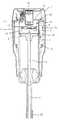
図1及び図2において符号1はガス燃焼式打ち込み工具(釘打機)の工具本体を示す。この工具本体1にはグリップとマガジン(図示せず)とが連接されているとともに、内部には燃焼室2と打撃ピストン・シリンダ機構が設けられている。工具本体1の下方には釘を打ち出すノーズ部3が設けられている。 1 and 2,
打撃ピストン・シリンダ機構は、打撃シリンダ4内に打撃ピストン5を摺動自在に収容するとともに、打撃ピストン5の下方にドライバ6を一体的に結合させたものである。 The striking piston / cylinder mechanism is configured such that a
ところで、打撃シリンダ4の上部延長上には筒状の隔壁部9が設けられ、隔壁部9の上端は工具本体1の上部ハウジング7の内部に形成されたシリンダヘッド部8の下面に突き合せ結合されている。また、隔壁部9の上部と下部にはそれぞれ開口部10、11が形成されている。 By the way, a cylindrical
なお、シリンダヘッド部8には点火プラグ12と回転ファン13が設けられている。点火プラグ12は燃焼室2内のガス燃料と空気との混合ガスに点火して燃焼させるためのものであり、また回転ファン13は、上記ガス燃料と空気とを撹拌混合するためのものであり、隔壁部9の中央に配置され、回転ファン13の先端と隔壁部9との間の隙間は小さくなるように形成され、また、回転ファン13の位置は、隔壁部9の上部開口部10と下部開口部11との間に配置されている。14は回転ファン13の駆動用モータである。また、図示しないが、シリンダヘッド部8にはガス容器に接続する燃料ガスの噴出ノズルが開口している。 The cylinder head 8 is provided with a
さらに、打撃シリンダ4の上部には燃焼室2を構成する可動スリーブ15が配置されている。可動スリーブ15は円筒状に形成され、打撃シリンダ4と上部ハウジング7の内部に形成されたシリンダヘッド部8との間に上下方向に摺動可能に配置されている。そして、図1のように下動したときは可動スリーブ15の内部に構成された燃焼室2は開放され、図2のように上動したときは、可動スリーブ15の内部には密閉した燃焼室2が形成されるようになっている。 Further, a
すなわち、シリンダヘッド部8の周縁は円形状に形成され、上記外周縁には上部Oリング16が設けられている。また、打撃シリンダ4の中間部の外周に膨出形成された環状摺動部17が形成され、該環状摺動部17の外周面の下部には一定の間隔をおいて開口溝18が抉り取られている。なお、環状摺動部17は少なくとも打撃ピストン5の上死点よりも下方に形成されている。 That is, the periphery of the cylinder head portion 8 is formed in a circular shape, and the upper O-
可動スリーブ15は中間部が膨らんだ筒状の部材で、打撃シリンダ4よりも大径に形成され、その下端は上記打撃シリンダ4の上部開口端よりも下方に延出されている。可動スリーブ15の上下部には小径部20、21が形成され、上部の小径部20の上端には一定の間隔をおいて突起部22が形成されている。隣り合う突起部22の間には開口溝23が形成されている。また、下部の小径部20の内周には下部Oリング24が周設されている。 The
上記可動スリーブ15の上部小径部20の内面は、シリンダヘッド部8の端面の上部Oリング16に摺動可能に配置され、また、可動スリーブ15の下部小径部20の下部Oリング24は、打撃シリンダ4の環状摺動部17の外面に摺動可能に配置されている。 The inner surface of the upper small-
上記構成により、可動スリーブ15が図1のように下動したときは、シリンダヘッド部8の上部Oリング16によるシールは解除され、燃焼室2の上部は開口溝23を通して外部に開放される。同様に、可動スリーブ15の下部Oリング24のシールも解除され、燃焼室2の下部は打撃シリンダ4の摺動部の開口溝18を通して外部に開放されている。これに対し、可動スリーブ15が図2のように上動したときは、上部Oリング16と下部Oリング24とによって燃焼室2はシールされて密閉状態となる。 With the above configuration, when the
また、上記隔壁部9により、中央部の燃焼室2aと隔壁部9の外側の燃焼室2bとが構成される。 Further, the
なお、可動スリーブ15は図示しないリンク部材を介してノーズ部3の先端に摺動自在に設けられたコンタクト部材25に連結している。コンタクト部材25はノーズ部3の先端から突出するようにバネ付勢されている。したがって、ノーズ部3を被打ち込み材に押し付けると、コンタクト部材25は押し込まれて上動するので、リンク部材を介して可動スリーブ15も上動し、図2のように密閉した燃焼室2が構成されるのである。逆に、ノーズ部3を被打ち込み材から離すと、コンタクト部材25は元の位置に移動するので、可動スリーブ15も下方に移動し、燃焼室2が開放されるのである。 The
次に、上記構成の釘打機の作動態様について説明する。まず釘の打ち込みに当たり、ノーズ部3を被打ち込み材に強く押しつけて工具本体1に対して相対的に上動させると、これに連動してコンタクト部材25とともに可動スリーブ15が上方に移動し、図2に示されるように、シリンダヘッド部8に設けられた上部Oリング16と打撃シリンダ4の上端外周に設けられた下部Oリング24によって密閉した燃焼室2が形成される。この燃焼室2内に噴射ノズルから可燃性ガスを噴射し、モータ14により回転ファン13を回転させて可燃性ガスと空気とを撹拌混合した後、トリガを引いて点火プラグ12で点火して爆発的に燃焼させる。これにより、打撃ピストン5が駆動され、ノーズ部3内に供給された釘が打ち出される。 Next, the operation mode of the nailing machine having the above configuration will be described. First, when the nail is driven, when the
これに対し、打ち込み終了後に、打撃ピストン5が復帰し、さらに上記コンタクトアームを被打ち込み材から離反させることにより、図1に示されるように可動スリーブ15を下方に移動させ、上記上部Oリング16と下部Oリング24によるシールが解除されて燃焼室2が開放され、上部の開口溝23からは新鮮な空気が入り込み、下部の開口溝18からは燃焼ガスが排気され、次の打ち込みが準備される。 On the other hand, after the driving is completed, the
上述のように、可動スリーブ15は打撃シリンダ4よりも大径で、その下端は打撃シリンダ4の上部開口端よりも下方に延出しているとともに、打撃シリンダ4には、可動スリーブ15の下端の開口部と摺動する摺動部17を上部開口端よりも下方に形成されているから、燃焼室2は打撃シリンダ4の上部だけでなく、打撃シリンダ4の周囲にも延長形成されることになる。打撃シリンダ4の周囲に増えた容積分だけ可動スリーブ15の高さを低くすることができる。したがって、図3に示すように、従来の釘打機A1の燃焼室2pに比べ、燃焼室における基本的な配置構造が維持され、従来の釘打機A1の燃焼室2pと同じ程度の所定の容積が確保することができるとともに、上記釘打機A1の全高L1に比べ、全高Lを低くすることができる。したがって、小型になり重量も軽くなるので、取り扱いが楽になり、また隅打ちなどの細かい作業にも使い勝手がよくなるとともに、燃焼エネルギは変わらないので、十分な打込み能力が得られる。 As described above, the
また、打撃シリンダ4の上端の延長上に筒状の隔壁部9を設け、該隔壁部9の上部と下部にそれぞれ開口部20、21を形成したから、燃焼室2の内部には、燃焼室2の中央部2aから下部開口部21を通って隔壁部9の外側の燃焼室2bの下部、さらに外側の燃焼室2bの下部から上部へ、外側の燃焼室2aの上部から上部開口部20を通って燃焼室2の中央部へと流れる流路が矢印のように形成される。このため、燃焼室2内に供給されたガス燃料と空気とを燃焼室2の中央の回転ファン13によって混合撹拌するときに、混合ガスは上記流路に沿って滞留することなく円滑に流れるため、撹拌混合の効率がよく、したがって混合ガスを確実に燃焼させることができる。 Further, since the
なお、実施例では可動スリーブを上下動することによって燃焼室が開閉する構成であることを説明したが、たとえば可動スリーブが回転することで燃焼室と可動スリーブ間で開閉する構成であってもよい。また、打撃シリンダ上端の延長上に筒状の隔壁部を設けた構成としているが、打撃シリンダとシリンダヘッド部をハウジング側に固定させて隔壁部を設けない構成でも可能である。 In the embodiment, it has been described that the combustion chamber opens and closes by moving the movable sleeve up and down. However, for example, a configuration in which the movable sleeve rotates and opens and closes between the combustion chamber and the movable sleeve may be employed. . In addition, although the cylindrical partition wall portion is provided on the extension of the upper end of the impact cylinder, a configuration in which the impact cylinder and the cylinder head portion are fixed to the housing side and the partition wall portion is not provided is also possible.
また、ガス燃料と空気とを混合する手段はファンに限定されない。 The means for mixing the gas fuel and air is not limited to the fan.
A ガス燃焼式打込み工具
2 燃焼室
4 打撃シリンダ
5 打撃ピストン
15 可動スリーブ
17 摺動部A Gas combustion
Claims (1)
Translated fromJapanese上記可動スリーブを上記打撃シリンダよりも大径とし、可動スリーブの下端を上記打撃シリンダの上部開口端よりも下方に延出し、打撃シリンダの外周には、可動スリーブの下端の開口部と摺動する環状摺動部を上部開口端よりも下方に形成し、
上記打撃シリンダの摺動部を、打撃シリンダ内に摺動自在に収容された打撃ピストンの上死点よりも下方に形成して、上記打撃シリンダの周囲において上記打撃ピストンの上死点よりも下方に燃焼室を延長形成し、
上記打撃シリンダの上端の延長上に筒状の隔壁部を設け、該隔壁部の上部と下部にそれぞれ開口部を形成したことを特徴とするガス燃焼式打込み工具。A cylinder head is provided above the striking cylinder that slidably accommodates the striking piston, and a cylindrical movable sleeve is movably disposed between the striking cylinder and the cylinder head, and is formed inside the movable sleeve. In the gas combustion type driving tool in which the combustion chamber is opened and closed by the movement of the movable sleeve, the mixed gas is ignited and burned in a sealed state, and exhaust and intake are made in an open state.
The movable sleeve has a larger diameter than the striking cylinder, the lower end of the movable sleeve extends below the upper opening end of the striking cylinder, and slides with the opening at the lower end of the movable sleeve on the outer periphery of the striking cylinder. An annular sliding part is formed below the upper opening end,
The sliding portion of the striking cylinder is formed below the top dead center of the striking piston slidably accommodated in the striking cylinder, and below the top dead center of the striking cylinder around the striking cylinder. The combustion chamber is extended to
A gas combustion type driving tool characterized in that acylindrical partition wall is provided on the extension of the upper end of the impact cylinder, and openings are formed in the upper and lower portions of the partition wall, respectively .
Priority Applications (7)
| Application Number | Priority Date | Filing Date | Title |
|---|---|---|---|
| JP2007171659AJP5070957B2 (en) | 2007-06-29 | 2007-06-29 | Gas fired driving tool |
| CN2008800194565ACN101678541B (en) | 2007-06-29 | 2008-06-24 | Gas combustion type driving tool |
| PCT/JP2008/061491WO2009004955A1 (en) | 2007-06-29 | 2008-06-24 | Gas combustion type driving tool |
| US12/666,933US8328059B2 (en) | 2007-06-29 | 2008-06-24 | Gas combustion type driving tool |
| KR1020097027199AKR20100030630A (en) | 2007-06-29 | 2008-06-24 | Gas combustion type driving tool |
| EP08777556.5AEP2163351B1 (en) | 2007-06-29 | 2008-06-24 | Gas combustion type driving tool |
| TW097123680ATWI448365B (en) | 2007-06-29 | 2008-06-25 | Gas burner percussion tool |
Applications Claiming Priority (1)
| Application Number | Priority Date | Filing Date | Title |
|---|---|---|---|
| JP2007171659AJP5070957B2 (en) | 2007-06-29 | 2007-06-29 | Gas fired driving tool |
Publications (2)
| Publication Number | Publication Date |
|---|---|
| JP2009006450A JP2009006450A (en) | 2009-01-15 |
| JP5070957B2true JP5070957B2 (en) | 2012-11-14 |
Family
ID=40226002
Family Applications (1)
| Application Number | Title | Priority Date | Filing Date |
|---|---|---|---|
| JP2007171659AExpired - Fee RelatedJP5070957B2 (en) | 2007-06-29 | 2007-06-29 | Gas fired driving tool |
Country Status (7)
| Country | Link |
|---|---|
| US (1) | US8328059B2 (en) |
| EP (1) | EP2163351B1 (en) |
| JP (1) | JP5070957B2 (en) |
| KR (1) | KR20100030630A (en) |
| CN (1) | CN101678541B (en) |
| TW (1) | TWI448365B (en) |
| WO (1) | WO2009004955A1 (en) |
Families Citing this family (1)
| Publication number | Priority date | Publication date | Assignee | Title |
|---|---|---|---|---|
| CN105674241B (en)* | 2016-03-29 | 2017-08-29 | 中南大学 | Constant volume type cleaning coal-firing device |
Family Cites Families (20)
| Publication number | Priority date | Publication date | Assignee | Title |
|---|---|---|---|---|
| US4483474A (en)* | 1981-01-22 | 1984-11-20 | Signode Corporation | Combustion gas-powered fastener driving tool |
| US4403722A (en) | 1981-01-22 | 1983-09-13 | Signode Corporation | Combustion gas powered fastener driving tool |
| US4483473A (en)* | 1983-05-02 | 1984-11-20 | Signode Corporation | Portable gas-powered fastener driving tool |
| EP0424941B1 (en)* | 1989-10-27 | 1994-01-05 | Hitachi Koki Co., Ltd. | Combustion gas powered fastener driving tool |
| JP2843117B2 (en) | 1990-06-15 | 1999-01-06 | 松下電工株式会社 | Incandescent lighting device |
| US5199626A (en)* | 1990-10-05 | 1993-04-06 | Hitachi Koki Company Limited | Combustion gas powered tool |
| US5191861A (en)* | 1991-07-12 | 1993-03-09 | Stanley-Bostitch, Inc. | Internal combustion actuated portable tool |
| US5320268A (en)* | 1993-04-13 | 1994-06-14 | Illinois Tool Works Inc. | Powered dimple-forming and fastener-driving tool |
| JPH08290370A (en)* | 1995-04-19 | 1996-11-05 | Japan Power Fastening Co Ltd | Gas combustion-type portable driving tool |
| JP2001162560A (en) | 1999-11-22 | 2001-06-19 | Prospection & Inventions Techniques Spit:Soc | Plug mounting device |
| US7040520B2 (en)* | 2002-09-12 | 2006-05-09 | Illinois Tool Works Inc. | Fan motor suspension mount for a combustion-powered tool |
| US6755159B1 (en) | 2003-01-20 | 2004-06-29 | Illinois Tool Works Inc. | Valve mechanisms for elongated combustion chambers |
| JP4125181B2 (en)* | 2003-06-02 | 2008-07-30 | 株式会社マキタ | Combustion work tool |
| JP4147403B2 (en)* | 2003-07-31 | 2008-09-10 | マックス株式会社 | Combustion chamber structure of gas-fired impact tool |
| JP4144472B2 (en)* | 2003-08-11 | 2008-09-03 | 日立工機株式会社 | Combustion power tool |
| JP4385743B2 (en)* | 2003-11-27 | 2009-12-16 | 日立工機株式会社 | Combustion power tool |
| JP4353110B2 (en)* | 2004-04-19 | 2009-10-28 | 日立工機株式会社 | Combustion nailer |
| CN100348370C (en)* | 2004-04-19 | 2007-11-14 | 日立工机株式会社 | Combustion-type power tool |
| JP4353076B2 (en)* | 2004-11-16 | 2009-10-28 | 日立工機株式会社 | Combustion power tool |
| US7931181B2 (en)* | 2005-02-18 | 2011-04-26 | Hitachi Koki Co., Ltd. | Combustion-type power tool with trigger control arrangements |
- 2007
- 2007-06-29JPJP2007171659Apatent/JP5070957B2/ennot_activeExpired - Fee Related
- 2008
- 2008-06-24WOPCT/JP2008/061491patent/WO2009004955A1/enactiveApplication Filing
- 2008-06-24USUS12/666,933patent/US8328059B2/ennot_activeExpired - Fee Related
- 2008-06-24KRKR1020097027199Apatent/KR20100030630A/ennot_activeWithdrawn
- 2008-06-24EPEP08777556.5Apatent/EP2163351B1/ennot_activeNot-in-force
- 2008-06-24CNCN2008800194565Apatent/CN101678541B/ennot_activeExpired - Fee Related
- 2008-06-25TWTW097123680Apatent/TWI448365B/ennot_activeIP Right Cessation
Also Published As
| Publication number | Publication date |
|---|---|
| CN101678541A (en) | 2010-03-24 |
| US8328059B2 (en) | 2012-12-11 |
| KR20100030630A (en) | 2010-03-18 |
| TWI448365B (en) | 2014-08-11 |
| EP2163351A1 (en) | 2010-03-17 |
| EP2163351A4 (en) | 2014-05-21 |
| TW200906577A (en) | 2009-02-16 |
| JP2009006450A (en) | 2009-01-15 |
| CN101678541B (en) | 2012-07-04 |
| EP2163351B1 (en) | 2016-07-06 |
| WO2009004955A1 (en) | 2009-01-08 |
| US20100140315A1 (en) | 2010-06-10 |
Similar Documents
| Publication | Publication Date | Title |
|---|---|---|
| AU2007292056B2 (en) | Combustion-type power tool | |
| US7490582B2 (en) | Combustion type power tool having fin for effectively cooling cylinder | |
| JP5055793B2 (en) | Gas fired driving tool | |
| US7063052B2 (en) | Combustion type power tool having fin in low turbulent combustion region within combustion chamber | |
| EP1693158A2 (en) | Combustion-type power tool having ignition proof arrangement | |
| JP2009006451A (en) | Gas combustion type driving tool | |
| JP4788228B2 (en) | Combustion chamber holding mechanism in gas combustion type driving tool | |
| JP5070957B2 (en) | Gas fired driving tool | |
| JP5070876B2 (en) | Gas fired driving tool | |
| JP5011900B2 (en) | Opening and closing mechanism of combustion chamber of gas combustion type driving tool | |
| JP5067095B2 (en) | Gas fired driving tool | |
| JP4992404B2 (en) | Gas fired driving tool | |
| JP2011000689A (en) | Combustion type power tool | |
| JP5045367B2 (en) | Gas fired driving tool | |
| JP4957899B2 (en) | Gas nailer combustion chamber structure | |
| JP5110251B2 (en) | Gas fired driving tool | |
| JP5435066B2 (en) | Gas fired driving tool | |
| JP5045297B2 (en) | Gas internal combustion type driving tool | |
| JP2003136424A (en) | Gas nailer | |
| JP2006224270A (en) | Combustion nailer |
Legal Events
| Date | Code | Title | Description |
|---|---|---|---|
| A621 | Written request for application examination | Free format text:JAPANESE INTERMEDIATE CODE: A621 Effective date:20100113 | |
| A131 | Notification of reasons for refusal | Free format text:JAPANESE INTERMEDIATE CODE: A131 Effective date:20120222 | |
| A521 | Request for written amendment filed | Free format text:JAPANESE INTERMEDIATE CODE: A523 Effective date:20120416 | |
| TRDD | Decision of grant or rejection written | ||
| A01 | Written decision to grant a patent or to grant a registration (utility model) | Free format text:JAPANESE INTERMEDIATE CODE: A01 Effective date:20120724 | |
| A01 | Written decision to grant a patent or to grant a registration (utility model) | Free format text:JAPANESE INTERMEDIATE CODE: A01 | |
| A61 | First payment of annual fees (during grant procedure) | Free format text:JAPANESE INTERMEDIATE CODE: A61 Effective date:20120806 | |
| R150 | Certificate of patent or registration of utility model | Ref document number:5070957 Country of ref document:JP Free format text:JAPANESE INTERMEDIATE CODE: R150 Free format text:JAPANESE INTERMEDIATE CODE: R150 | |
| FPAY | Renewal fee payment (event date is renewal date of database) | Free format text:PAYMENT UNTIL: 20150831 Year of fee payment:3 | |
| LAPS | Cancellation because of no payment of annual fees |