JP5066123B2 - Vehicle driving support device - Google Patents
Vehicle driving support deviceDownload PDFInfo
- Publication number
- JP5066123B2 JP5066123B2JP2009071559AJP2009071559AJP5066123B2JP 5066123 B2JP5066123 B2JP 5066123B2JP 2009071559 AJP2009071559 AJP 2009071559AJP 2009071559 AJP2009071559 AJP 2009071559AJP 5066123 B2JP5066123 B2JP 5066123B2
- Authority
- JP
- Japan
- Prior art keywords
- lane
- white line
- host vehicle
- vehicle
- unit
- Prior art date
- Legal status (The legal status is an assumption and is not a legal conclusion. Google has not performed a legal analysis and makes no representation as to the accuracy of the status listed.)
- Expired - Fee Related
Links
Images


Classifications
- G—PHYSICS
- G06—COMPUTING OR CALCULATING; COUNTING
- G06V—IMAGE OR VIDEO RECOGNITION OR UNDERSTANDING
- G06V20/00—Scenes; Scene-specific elements
- G06V20/50—Context or environment of the image
- G06V20/56—Context or environment of the image exterior to a vehicle by using sensors mounted on the vehicle
- G06V20/588—Recognition of the road, e.g. of lane markings; Recognition of the vehicle driving pattern in relation to the road
Landscapes
- Engineering & Computer Science (AREA)
- Physics & Mathematics (AREA)
- General Physics & Mathematics (AREA)
- Multimedia (AREA)
- Theoretical Computer Science (AREA)
- Traffic Control Systems (AREA)
- Control Of Driving Devices And Active Controlling Of Vehicle (AREA)
- Control Of Vehicle Engines Or Engines For Specific Uses (AREA)
- Regulating Braking Force (AREA)
Description
Translated fromJapanese本発明は、走行中の自車両の走行車線をリアルタイムで特定して車両制御を行うようにした車両運転支援装置に関するものである。 The present invention relates to a vehicle driving support apparatus that performs vehicle control by specifying a traveling lane of a traveling vehicle in real time.
この種の技術として、自車両の走行中の路面をカメラ等にて撮像し、自車両の走行車線を区分している路面の白線を画像認識処理にてリアルタイムで認識して、例えば車線維持制御等の車両制御をもって運転支援を行うようにしたものが既に知られている。 As this kind of technology, the road surface of the host vehicle traveling is imaged with a camera or the like, and the white line on the road surface that divides the host vehicle lane is recognized in real time by image recognition processing, for example, lane maintenance control. There is already known one that performs driving support with vehicle control such as the above.
そして、例えば高速道路等のように交通量の多い場所では、路面上の一部の白線が掠れや汚れ等のために不明瞭なことがあり、このような場合には自車両の走行車線を区分している路面の白線を認識できないことになる。 And in places with a lot of traffic such as highways, some white lines on the road surface may be unclear due to drowning or dirt. It will not be possible to recognize the white lines on the road surface that is being segmented.
その対策として、特許文献1には、走行車線を区分している白線を認識することができなかった場合には、自車両の前方の先行車両の移動軌跡と予想移動軌跡を演算し、これらの移動軌跡および予想移動軌跡に基づいて走行車線の仮想白線を描き、もって走行車線を推定し、これを目標車線として設定するようにしたものが提案されている。 As a countermeasure,
特許文献1に記載の技術では、自車両の走行車線を区分している路面の白線を認識できなかった場合に、先行車両の移動軌跡や予想移動軌跡に基づいて走行車線を推定しているため、先行車両に追従する車線維持制御(レーンキープ制御)や車線逸脱警報等の制御には有効ではある。その一方、同特許文献1に記載の技術では、リアルタイムでの演算負荷が極端に大きくなるだけでなく、先行車の動きに依存しない自律的な制御、例えば高速道路のインターチェンジでの分岐に際して、自車両の走行車線と、本線から分岐路側への車線変更を特定した上で、分岐先のカーブ曲率等に応じた車速制御を行うような場合には適用することができず、なおも改善の余地を残している。 In the technique described in
本発明はこのような課題に着目してなされたものであり、先に述べた掠れや汚れ等のために自車両の走行車線を区分している路面の白線を認識できない場合でも、その白線を容易に推定して、自律的な車両制御を行えるようにした車両運転支援装置を提供するものである。 The present invention has been made paying attention to such a problem, and even when the white line on the road surface that divides the traveling lane of the host vehicle cannot be recognized due to the above-described drowning or dirt, the white line is displayed. The present invention provides a vehicle driving support device that can be easily estimated and can perform autonomous vehicle control.
本発明は、自車両の走行車線を区分している路面の白線を認識できない場合でも、自車両が車線変更しないかぎりは当該自車両の走行車線を区分している左右の白線の種別は変わることがない点に着目し、自車両の現在の走行車線を区分する白線の種別を画像処理等によりリアルタイムで認識して、その認識した白線の種別を走行履歴のかたちで記憶しておき、白線の種別を認識ができないときには、記憶されている過去の白線の種別を自車両の現在の走行車線を区分する白線の種別として推定し、それに基づいて車両制御を行うようにしたものである。 In the present invention, even when the white line on the road surface that divides the traveling lane of the own vehicle cannot be recognized, the types of the left and right white lines that divide the traveling lane of the own vehicle change unless the own vehicle changes the lane. Focusing on the fact that there is no white line, the type of white line that divides the current driving lane of the host vehicle is recognized in real time by image processing etc., and the recognized white line type is stored in the form of the driving history, When the type cannot be recognized, the stored type of the past white line is estimated as the type of the white line that divides the current travel lane of the host vehicle, and vehicle control is performed based on the estimated type.
本発明によれば、自車両の現在の走行車線を区分する白線の種別を認識できない場合でも、過去の履歴から白線種別情報を取得してその白線種別を推定することができるので、継続的な運転支援として自車両の現在の走行車線に基づいた自律的な車両制御を継続して行えるようになる。 According to the present invention, even when the type of the white line that divides the current traveling lane of the host vehicle cannot be recognized, the white line type information can be acquired from the past history and the white line type can be estimated. As a driving support, autonomous vehicle control based on the current travel lane of the host vehicle can be continued.
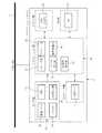
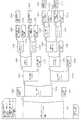
図1〜図18は本発明に係る車両運転支援装置のより具体的な第1の実施の形態を示す図であり、特に図1はシステム全体の大まかな概略構造を示し、また図2〜5は図1のシステムを構成している各装置の内部機能ブロック図を示している。 1 to 18 are views showing a more specific first embodiment of the vehicle driving support apparatus according to the present invention. In particular, FIG. 1 shows a rough schematic structure of the entire system, and FIGS. FIG. 2 shows an internal functional block diagram of each device constituting the system of FIG.
ここでは、例えば高速道路での走行中において、自車両の走行車線と、本線から出口路(出口車線)等の分岐路側へ車線変更したか否かを、後述するカメラ情報やナビゲーションシステムからの道路情報に基づいて特定して、分岐路側へ車線変更したと特定された場合には、その分岐先のカーブ曲率に応じた車速制御を行う場合を想定している。 Here, for example, when traveling on an expressway, whether the lane of the host vehicle has been changed from the main lane to the branch road side such as an exit lane (exit lane) is determined by the camera information and the road from the navigation system described later. When it is specified based on the information and it is specified that the lane has been changed to the branch road side, it is assumed that vehicle speed control is performed according to the curve curvature of the branch destination.
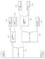
図1のシステムでは、大きく分けて、自車両Cに搭載された路面状態検出装置1と、走行車線推定装置2と、ナビゲーションシステム3、および車両制御装置4等との協調システムとして構成されている。これらの各要素1〜4同士は車両通信ラインである車載LANとして機能するCAN(Vehicle−Control Area Network)ライン5を経由してネットワークを構築していて、このCANライン5経由にて相互に必要な信号の授受が行われる。 The system of FIG. 1 is broadly configured as a cooperative system of a road surface
また、車体後部には路面を指向する撮像部あるいは撮像手段としてリアカメラ6が配置されていて、このリアカメラ6が捉えた映像がリアルタイムで路面状態検出装置1に取り込まれることになる。 In addition, a
ここで、図1のほか図6に示すように、リアカメラ6は、後述するように少なくとも自車両Cの走行中の走行車線を区分している左右の白線L1,L2を捕捉することを主たる目的としており(図6の左半部参照)、したがって、少なくとも自車両Cの走行中の左右の白線L1,L2を捕捉することができるようにその画角および向きが予め調整されている。この場合において、リアカメラ6と同等の機能が発揮されるならば、当該リアカメラ6に代えて、フロントカメラあるいはサイドカメラ等であっても良い。 Here, as shown in FIG. 6 in addition to FIG. 1, the
上記路面状態検出装置1は、リアカメラ6からの映像を入力とする画像認識処理部として構成されているもので、図2に示すように、アプリケーション層7として、例えば高速道路での走行中において自車両の現在の走行車線を区分する白線を抽出してその種別(白線のパターン)を認識する白線種別認識部(白線パターン認識部)8と、認識された白線種別を記憶する白線種別記憶部(白線パターン記憶部)9と、白線種別認識部9による白線の種別が不明なときに上記白線種別記憶部9に記憶されている白線の種別を、自車両Cの現在の走行車線を区分する白線の種別として推定する白線種別推定部(白線パターン推定部)10と、自車両Cが走行車線の左右のいずれかの白線を跨いだことを検知する白線跨ぎ検出部11とを備えている。さらに、路面状態検出装置1はドライバ層としてCAN入出力部12を備えている。 The road surface
そして、この路面状態検出装置1には、図1,6にも示したように、自車両Cに搭載されたリアカメラ6が捉えた映像がリアルタイムで入力されることから、所定の画像認識処理を実行することで、少なくとも自車両Cの現在の走行車線を区分している左右の白線L1,L2の種別が特定されるとともに(図6の左半部参照)、自車両Cが例えば特定の白線L3を跨いだことに基づく車線変更とその方向(図6の右半部参照)が特定されることになる。これらの路面状態検出装置1にて得られた情報は、必要に応じて走行車線推定装置2や車両制御装置4に対してCANライン5経由にて出力される。なお、当該路面状態検出装置1での処理の詳細は後述する。 As shown in FIGS. 1 and 6, since the video captured by the
また、走行車線推定装置2は、上記路面状態検出装置1等からの情報をもとに自車両Cの走行車線を特定する機能を有していて、図3に示すように、自車走行車線推定部14と、車両運動検出部16および車線変更判断部17をアプリケーション層13として備えているほか、ドライバ層としてCAN入出力部18を備えている。さらに、アプリケーション層13に、自車両Cの走行車線に加えて自車前方の分岐形状を特定するために必要に応じて分岐形状特定部15を備えている。 The travel
この分岐形状特定部15は、上記ナビゲーションシステム3の地図データ21から取得した道路情報をもとに例えば自車前方のインターチェンジあるいはジャンクション等の分岐部の存在を認識し、その分岐形状を特定する機能を有する。なお、分岐形状特定部15は本実施の形態ではその機能を必要としないが、後述する第2の実施の形態で有効に機能する。 The branch
上記自車走行車線推定部14は、路面状態検出装置1側の白線種別認識部8の認識結果と白線種別推定部10の推定結果に基づき自車両Cの走行車線を推定する機能を有する。車両運動検出部16は、方向指示器(ウインカー)の操作による車線変更等の意思表示のほか、車載下にあるヨーレートセンサや舵角センサの出力に基づいて車両運動が発生したことを検出する機能を有する。また、車線変更判断部17は、上記分岐形状特定部15で特定された分岐形状や自車走行車線推定部14で推定された走行車線のほか、上記白線跨ぎ検出部11および車両運動検出部16での検出結果に基づいて、自車両Cが本線から分岐路側へ車線変更したか否かを判断する機能を有している。なお、これらの各部の機能の詳細についも後述する。 The host vehicle traveling
ナビゲーションシステム3は、図4に示したように、大きく分けてアプリケーション層19、センサ層20、地図データ層としての地図データ(地図データベース)21、ドライバ層としてのCAN入出力部22およびHMI(ヒューマン−マシン−インタフェース)層としてのHMI部23を備えている。地図データ21は、例えばCD−ROMやDVDあるいはハードディスク等の記録媒体で構成されていて、周知のように例えば道路属性情報や道路構造情報を含む地図情報が予め格納されている。この地図情報には先に述べた高速道路上のインターチェンジあるいはジャンクション等の分岐情報のほか、サービスエリア(SA)やパーキングエリア(PA)に関する情報が含まれている。 As shown in FIG. 4, the
上記HMI部23は周知のように液晶ディスプレイ等のモニタ手段やマイクおよびスピーカ等を含みつつ各種の操作部として機能するもので、ナビゲーションシステム3の各種の操作スイッチ等がこれに含まれることになる。また、後述する音声ガイダンス機能も告知部として当該HMI部23に含まれることになる。 As is well known, the
上記センサ層20には、ジャイロスコープ24およびGPSチューナ25等が含まれているほか、車両の車速パルスセンサ25や方向指示器26の信号が取り込まれる。 The
上記ナビゲーションシステム3のアプリケーション層19には、ロケータ部27と、プレビュー部(先読み機能部)28、ロケータ補正部29および曲率演算部30が含まれている。さらに、アプリケーション層19には、必要に応じてSA速度司令部31が含まれている。なお、SA速度司令部31は本実施の形態ではその機能を必要としないが、後述する第3の実施の形態では有効に機能する。 The
ロケータ部27は自車位置を演算する機能を有し、プレビュー部28は地図データ21にアクセスして自車両Cの前方の道路情報を取得する機能を有する。ロケータ補正部29は図3の車線変更判断部17での判断結果に基づき自車両Cの位置をインターチェンジ等での分岐先に合わせて位置補正を行う機能を有する。また、曲率演算部30は、自車両Cの前方のカーブの曲率を演算する機能を有する。さらに、SA速度司令部31は、自車両Cがサービスエリア(SA)またはパーキングエリア(PA)内に進入したと判断された場合に、そのサービスエリア(SA)またはパーキングエリア(PA)内での適切な速度指令を出力する機能を有する。なお、これらの各部の機能の詳細は後述する。 The
そして、上記ナビゲーションシステム3では、その基本機能として、ジャイロスコープ24やGPSチューナ25等のセンサ情報から自車両Cの位置を決定した上で、自車両Cが走行する経路を推定し(いわゆる進路推定機能)、進路推定した経路の曲率値を演算によって算出する。さらに、進路推定した経路上の自車前方に当該自車両Cが分岐すべき分岐部(分岐ノード)がある場合には、その分岐ノードまでの距離を演算して求めるとともに、本線車線に対する分岐先の方向)を特定する。そして、それらの情報を定期周期にてCANライン5経由で走行車線推定装置2や車両制御装置4側に出力することになる。 In the
上記車両制御装置4には、図5に示すように、ドライバ層としてのCAN入出力部32のほか、アプリケーション層33として目標車速演算部34および車速司令部35が含まれていて、さらに必要に応じて車速制御自動キャンセル部36が含まれている。なお、車速制御自動キャンセル部36は、上記分岐形状特定部15およびSA速度司令部31と同様に本実施の形態では必ずしもその機能を必要としないが、後述する第3の実施の形態では有効に機能する。 As shown in FIG. 5, the
そして、先に述べたように、推定経路上において自車両Cの前方に所定曲率のカーブの存在を認識した場合には、目標車速演算部34ではそのカーブの曲率に応じた最適な目標車速を演算によって求める。こうして目標車速が求まると、車速指令部35はその目標車速に応じた車速指令を減速指令としてCANライン5経由にてブレーキ制御装置37やエンジン制御装置38に出力することになる。 As described above, when the presence of a curve with a predetermined curvature is recognized in front of the host vehicle C on the estimated route, the target vehicle
これにより、例えばブレーキ制御装置37がブレーキアクチュエータを、エンジン制御装置38がスロットルアクチュエータをそれぞれ駆動して、現在の車速が目標車速となるようにいわゆる自動車速モードでの車速制御を実行することになる。なお、ここではブレーキ制御装置37およびエンジン制御装置38を例示しているが、これら以外の車速制御のための手段として自動変速機制御装置が含まれることもある。 Thus, for example, the
ここで、図5の車速制御自動キャンセル部36は、後述するように、例えば自車両Cが特定のエリア、例えば先に述べたサービスエリア(SA)またはパーキングエリア(PA)内に進入する場合に、安全性を考慮して上記のような車速制御を自動的にキャンセルする機能を有する。 Here, as will be described later, the vehicle speed control
次に、図2〜5に示した各装置、すなわちナビゲーションシステム3のほか、路面状態検出装置1と走行車線推定装置2および車両制御装置4等のそれぞれの機能について、図7以下のフローチャートを参照しながら詳しく説明する。 Next, in addition to the devices shown in FIGS. 2 to 5, that is, the
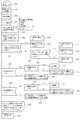
図4のナビゲーションシステム3では、図7に示すように、特定の周期にて、車速パルスセンサ25からの車速信号のほかジャイロスコープ24やGPSチューナ25等のセンサ情報から自車位置情報を取得した上で(ステップS1)、自車両前方道路情報を含む自車両Cの周辺の地図データをいわゆるプレビュー機能により収集し(ステップS2)、この収集した地図データから自車両Cが走行する経路をいわゆる進路推定機能により推定する(S3)。進路推定の方法は、ナビゲーションシステム3に目的地が設定されている場合には、周知のように自車位置から目的地まで誘導経路が引かれていることから、その誘導経路上を推定進路として設定する。 In the
その一方、ナビゲーションシステム3に目的地が設定されていない場合には、道路上の分岐部(分岐ノード)での前方と後方の道路種別(例えば国道か都道府県道か)あるいはリンク種別を比較し、同一の道路種別あるいはリンク種別のリンク(経路)を優先的に選択する。なお、分岐点前方と後方のリンクの道路種別あるいはリンク種別に違いがない場合には、リンク角の小さいリンク(経路)を選択して推定進路として設定する。 On the other hand, if the destination is not set in the
自車両Cの進路が推定されたならば、ナビゲーションシステム3の曲率演算部30の機能として、進路推定した経路の曲率値を演算によって算出する(ステップS4)。 If the course of the host vehicle C is estimated, the curvature value of the route estimated path is calculated by calculation as a function of the
さらに、進路推定した経路上の自車前方に当該自車両Cが分岐すべき分岐部(分岐ノード)がある場合、例えば高速道路上の自車両の前方に当該自車両が分岐すべきインターチェンジあるいはジャンクション等の分岐部がある場合には、その分岐ノード周辺の道路種別とリンク種別の情報を取得した上で(ステップS5)、その分岐ノードまでの距離を演算して求めるとともに(ステップS6)、本線車線に対する分岐先の方向(例えば、インターチェンジの場合には本線車線に対する出口車線の方向であり、サービスエリア(SA)またはパーキングエリア(PA)の場合には本線車線に対する各エリアの入口車線の方向)を特定する(ステップS7)。そして、それらの情報を定期周期にてCANライン5経由で走行車線推定装置2や車両制御装置4側に出力することになる(ステップS8)。 Further, when there is a branching part (branch node) where the host vehicle C should branch in front of the host vehicle on the estimated route, for example, an interchange or junction where the host vehicle should branch in front of the host vehicle on the highway. If there is a branching section such as, the road type and link type information around the branch node is obtained (step S5), the distance to the branch node is calculated and obtained (step S6), and the main line The direction of the branch destination with respect to the lane (for example, the direction of the exit lane with respect to the main lane in the case of an interchange, and the direction of the entrance lane of each area with respect to the main lane in the case of a service area (SA) or parking area (PA)) Is specified (step S7). Then, such information is output to the traveling
上記のようなナビゲーションシステム3からの情報を取得した図5の車両制御装置4では、図8に示すように、目標車速演算部34にて自車前方のリンクの曲率値情報に応じた目標車速を演算した上で(ステップS11,S12)、これを車速司令部35からブレーキ制御装置37やエンジン制御装置38に出力することになる(ステップS13)。 In the
これにより、先に述べたように、例えばブレーキ制御装置37がブレーキアクチュエータを、エンジン制御装置38がスロットルアクチュエータをそれぞれ駆動して、現在の車速が目標車速となるようにいわゆる自動車速モードでの車速制御を実行することになる。 Accordingly, as described above, for example, the
この場合において、例えば図6のようなインターチェンジでの分岐に際し、自車両Cがインターチェンジの出口車線に進入したことを確認した上で車速制御を実行するためには、それに先立って予め自車両Cの走行車線を特定しておく必要がある。この自車両Cの走行車線の推定を後述するように図3の走行車線推定装置2が実行することになるのであるが、図9に示すように、同図の分岐ノードP1をはさんでその前後に車線推定開始位置Es(例えば、分岐ノードP1よりも数十メートルだけ手前の位置)と車線推定終了位置Ee(例えば、分岐ノードP1よりも数十メートルだけ先の位置)を定め、両者の間を車線推定エリアEとして予め設定しておき、この車線推定エリアEにおいてのみ後述する走行車線推定装置2による自車両Cの走行車線推定を実行するものとする。こうすることにより、自車両Cの走行車線推定を常時実行する場合に比べて走行車線推定装置2の負荷を軽減できることになる。 In this case, for example, in order to execute vehicle speed control after confirming that the host vehicle C has entered the exit lane of the interchange when branching at an interchange as shown in FIG. The driving lane needs to be specified. As will be described later, the travel
また、上記ナビゲーションシステム3におけるプレビュー部28が収集・取得した地図情報に含まれる道路データは、周知のように基本的には交差点や分岐点の座標を表すノードとそれらのノード間を接続するリンクとで構成されていることから(リンクの途中にノードと同等の補間点(補間ノード)が設定されることもある)、上記のように進路推定した経路の曲率値とは、ある特定のノードの手前側のリンクと当該ノードの前方側のリンクとのなす角度、あるいはその角度に基づき所定演算式にて算出した値(曲率半径)と定義するものとする。なお、上記曲率値はそれぞれのノードに関連付けて地図データ21に予め記録しておいても良い。 The road data included in the map information collected / acquired by the
一方、図1,2の路面状態検出装置1では、自車両Cに搭載されたリアカメラ6が捉えた映像がリアルタイムで当該路面状態検出装置1に入力されることから、図10に示すように、所定の周期にて、入力された映像にA/D変換および二値化の各処理を施した上で(ステップS21〜S23)、自車両Cの現在の走行車線を区分している左右の白線(図6の左半部参照)のエッジを画像から抽出して実質的にその白線部分のみを抽出する(ステップS24)。そして、パターン認識その他の画像認識処理をもって白線種別判定を行って、自車両Cの左右の白線の種別を検知、すなわちその白線の種別を図11の6種類のなかから判定または認識(特定)する(ステップS25)。これらの処理は図2の路面状態検出装置1における白線種別認識部8の処理として実行される。 On the other hand, in the road surface
さらに、後述するように、自車両Cが特定の白線を跨いだ場合には、それによって車線変更の有無と方向が特定され(図10のステップS26)、それらの結果がCANライン5経由にて図3の走行車線推定装置2等に出力されることになる(ステップS27)。 Furthermore, as will be described later, when the host vehicle C crosses a specific white line, the presence / absence and direction of the lane change are specified thereby (step S26 in FIG. 10), and those results are obtained via the
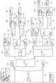
図10の処理内容をより詳しく説明したものを図12に示してある。 FIG. 12 shows the details of the processing in FIG. 10 in detail.
図12のステップS31〜S35は、図10のステップS21〜S25と同じであり、上記のような白線種別認識部8による白線種別の認識結果、すなわち自車両Cの現在の走行車線を区分している左右の白線種別の認識結果は、後述するステップS48,S53において走行履歴データとして図2の路面状態検出装置1の白線種別記憶部9にその都度書き込まれて記憶される。すなわち、図2の路面状態検出装置1における白線種別記憶部9には、上記のような左右の白線種別の認識結果が自車両Cの走行履歴に基づくデータとして逐一記憶・蓄積されるようになっていることから、上記のような白線種別認識部8による左右の白線種別の認識結果はその都度、左右別々の白線種別記憶部9に書き込まれることになる。 Steps S31 to S35 in FIG. 12 are the same as steps S21 to S25 in FIG. 10, and the white line type recognition result by the white line type recognition unit 8 as described above, that is, the current traveling lane of the host vehicle C is classified. The recognition results of the left and right white line types are written and stored in the white line
ここで、例えば主要高速道路において認識すべき白線の種別は、図11のように車両通行帯の表示に用いられているものとする。この場合において、「太破線」は高速道路等の入口または出口等の付近に設置される車両通行帯最外側線と定義される(図6および図9参照)。ただし、図11の「白線無し」は白線を認識しない場合であり、後述する白線の種別が「不明」とは異なる。「白線無し」は白線そのものが検知できない場合であるのに対して、白線の種別が「不明」とは、白線としては検知できているが、その白線の種別(例えば実線なのか破線なのか)が判別または判定できない場合であるからである。 Here, for example, the type of the white line to be recognized on the main highway is assumed to be used for displaying the vehicle lane as shown in FIG. In this case, the “thick broken line” is defined as the outermost line of the vehicle lane that is installed near the entrance or exit of an expressway or the like (see FIGS. 6 and 9). However, “no white line” in FIG. 11 is a case where a white line is not recognized, and the type of white line described later is different from “unknown”. “No white line” is a case where the white line itself cannot be detected, while “Unknown” is a white line type that is detected as a white line, but the type of the white line (for example, whether it is a solid line or a broken line) This is because it is a case where cannot be determined or determined.
上記のように自車両Cの左右の白線種別が認識されたならば、その認識した左右の白線の位置関係を図2の路面状態検出装置1における白線跨ぎ検出部11が常時トラッキング(追跡)していて(図12のステップS36)、例えば同図のステップS37のように、トラッキング中の左側の白線が自車両Cの「白線跨ぎ」をもって当該自車両Cの右方向へ移動した場合には、これを白線跨ぎ検出部11が直ちに「白線跨ぎ検知=ON」をもって「車線変更の方向=左」として検出する(ステップS38,S39)。 If the left and right white line types of the host vehicle C are recognized as described above, the white line straddling
例えば、図6に示すように、インターチェンジの出口車線側への分岐近くにおいて、それまで左側白線を「実線」、右側白線を「破線」としてそれぞれ認識して走行していた自車両Cが左側白線を「太破線」として認識した以降に左側に向きを変えると、路面状態検出装置1の白線跨ぎ検出部11が左側の「太破線」を跨いだと判断するので、これをもって上記のように自車両Cの「左方向への車線変更」として検出することになる。 For example, as shown in FIG. 6, near the intersection of the interchange toward the exit lane, the host vehicle C, which has been running until then, recognizes the left white line as a “solid line” and the right white line as a “dashed line”. If the direction is changed to the left after recognizing as “thick broken line”, the white line straddling
同様に、図13に示すように、インターチェンジの出口車線側への分岐近くにおいて、それまで左側白線を「実線」、右側白線を「破線」としてそれぞれ認識して走行していた自車両Cが左側に向きを変えると、路面状態検出装置1では「太破線」を認識する以前に白線跨ぎ検出部11が左側の「実線」を跨いだとして判断するので、これをもって上記のように自車両Cの「左方向への車線変更」として検出することになる。 Similarly, as shown in FIG. 13, near the intersection of the interchange toward the exit lane, the host vehicle C that has been traveling by recognizing the left white line as a “solid line” and the right white line as a “dashed line” When the direction is changed, the road surface
これらのことは右側の白線を跨いだ場合にも全く同様であって、図12のステップS40〜S42のように、トラッキング中の右側の白線が自車両の「白線跨ぎ」をもって当該自車両の左方向へ移動した場合には、これを白線跨ぎ検出部11が「白線跨ぎ検知=ON」をもって直ちに「右方向への車線変更」として検出することになる。 These are exactly the same when the white line on the right side is straddled. As shown in steps S40 to S42 in FIG. 12, the right white line being tracked has the “white line straddle” of the own vehicle and the left side of the own vehicle. When the vehicle moves in the direction, the white line straddling
以上のような白線種別の認識過程において、一般に道路上に描かれた白線はペイント等によるものであるために、例えば掠れや汚れ等のためにその種別が特定できないことがある。特に、図6,13に示したようなインターチェンジの出口車線側への分岐部における「太破線」は、車線変更に際して多くの車両が通過することになるために、掠れによって不鮮明になりやすく、路面状態検出装置1では認識できないことがある。天候によってもまた同様である。 In the process of recognizing the white line type as described above, since the white line drawn on the road is generally due to paint or the like, the type may not be specified due to, for example, drowning or dirt. In particular, the “thick broken line” in the branch to the exit lane side of the interchange as shown in FIGS. 6 and 13 is likely to become blurred due to drowning because many vehicles pass when changing lanes. The
より具体的には、例えば路面状態検出装置1での画像認識により白線としては認識できたとしても、その白線が「実線」なのか「破線」なのか、あるいは「破線」なのか「太破線」なのかを特定または判別できないことがある。このような場合には、図12のステップS35における白線種別の認識の際に、左側または右側の白線の種別が「不明」と判定される。 More specifically, for example, even if it can be recognized as a white line by image recognition in the road surface
そこで、本実施の形態では、上記のように一時的に左側あるいは右側の白線の種別が不明であっても、自車両が車線変更しないかぎりは左右の白線の種別はそれ以前の白線種別と変わることはないとの点に着目して、左側または右側の白線種別が不明である場合には、路面状態検出装置1の白線種別記憶部9に走行履歴データとして記憶されている過去の白線種別情報から現在の左側または右側の白線の種別を推定するものとする。 Therefore, in the present embodiment, even if the type of the white line on the left or right side is temporarily unknown as described above, the type of the white line on the left and right will change from the previous white line type unless the vehicle changes lanes. If the left or right white line type is unknown, the past white line type information stored as the travel history data in the white line
例えば、図12のステップS44において、自車両Cの現在における左側の白線の種別が「不明」と判定された場合には、図2の路面状態検出装置1における白線種別推定部9では、白線跨ぎ検出部11における「白線跨ぎ検出=OFF」をもって自車両が車線変更していないことを条件に(ステップS45)、白線種別記憶部9に白線種別を書き込むのに代えて、白線種別推定部10がステップS46において当該白線種別記憶部9に記憶されている以前の白線種別情報を呼び出して、これを自車両の現在における左側の白線の種別として推定する。なお、ステップS46では白線種別記憶部9に白線種別を書き込まないために「処理無し」と記載してある。これは、左側の白線の種別が「不明」とされる以前の左側の白線の種別をそのまま現在の左側の白線の種別として推定していることにほかならない。 For example, if it is determined in step S44 in FIG. 12 that the current white line type of the vehicle C is “unknown”, the white line
他方、図12のステップS44において自車両Cの現在における左側の白線の種別が「不明」と判定された場合であって、且つ図2の路面状態検出装置1における白線跨ぎ検出部11が「白線跨ぎ検出=ON」をもって自車両が車線変更したと判定した場合には、白線種別推定部10では先のステップS35での白線種別の認識結果をもとに現在の左側の白線種別が依然として「不明」のままと判定し、ステップS47においてこの情報を白線種別記憶部9に書き込む。 On the other hand, when the type of the current white line on the left side of the host vehicle C is determined to be “unknown” in step S44 of FIG. 12, the white line straddling
ただし、現在の左側の白線種別が「不明」とされた場合でも、先にも述べたように白線としては認識しているので、「白線跨ぎ」による左方向または右方向への車線変更の判断には支障はないことになる。また、上記のようにある地点において一時的には左側あるいは右側の白線種別が不明であっても、次の地点での白線種別の認識の際にはその認識された白線種別が書き込まれることになる。 However, even if the current white line type on the left side is “Unknown”, it is recognized as a white line as described above, so it is determined whether to change the lane to the left or right by “crossing the white line”. There will be no hindrance. In addition, even if the left or right white line type is temporarily unknown at a certain point as described above, the recognized white line type is written when the white line type is recognized at the next point. Become.
このような処理は、ステップS49〜S52において、自車両Cの現在の右側の白線種別が「不明」と判定された場合にも同様である。 This process is the same when the current white line type on the right side of the host vehicle C is determined to be “unknown” in steps S49 to S52.
そして、先にも述べたように、ステップS35において認識された左右の白線種別、すなわち、「不明」とされずに正しく認識された左右の白線種別は、ステップS47,S52と同様にして、ステップS48,S53において図2の路面状態検出装置1の白線種別記憶部9に走行履歴データとしてその都度書き込まれて記憶される。 As described above, the left and right white line types recognized in step S35, that is, the left and right white line types recognized correctly without being “unknown”, are the same as in steps S47 and S52. In S48 and S53, it is written and stored as travel history data each time in the white line
この後、図12のステップS46,S51にて推定された左右の白線種別情報のほか、同じくステップS47,S52およびステップS48,S53にて先に白線種別記憶部9に書き込まれた左右の白線種別の情報、白線跨ぎ検出部11による「白線跨ぎ」検出結果、およびそれに基づく車線変更の有無とその方向に関する情報が、路面状態検出装置1から走行車線推定装置2等に向けてCANライン5経由にて出力される(ステップS54)。 Thereafter, in addition to the left and right white line type information estimated in steps S46 and S51 in FIG. 12, the left and right white line types previously written in the white line
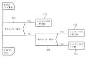
ここで、図10および図12の処理を機能ブロック図的に集約すると図14のようになる。 Here, the processing of FIGS. 10 and 12 is summarized in a functional block diagram as shown in FIG.
図15は図3の走行車線推定装置2における自車走行車線推定部14での処理手順を示している。 FIG. 15 shows a processing procedure in the own vehicle travel
この自車走行車線推定部14での処理は、先に図9に示したように、自車両Cの推定経路上において例えば左出口車線への分岐部の前後に設定された車線推定エリアEに自車両Cがあることを条件に、上記路面状態検出装置1等からの情報をもとに実行される。 As shown in FIG. 9, the processing in the own vehicle travel
図6のほか図15において、出口車線が左側であるか右側であるかの情報は先にナビゲーションシステム3から与えられていて既知であり(ステップS41)、図6のように出口車線が左側である場合には、次のステップS42において自車両Cが認識している左側の白線種別が「実線」である否かを判定する。 In addition to FIG. 6, in FIG. 15, information on whether the exit lane is the left side or the right side is given from the
ここで、最初に左側の白線種別が「実線」である否かを判定しているのは、一般的な高速道路の場合には車両通行帯の左右の最外側線は実線で描かれていて、左端車線または右端車線を特定するのに最も効果的であるからである。 Here, it is first determined whether or not the left white line type is “solid line”. In the case of a general highway, the left and right outermost lines of the vehicle lane are drawn with solid lines. This is because it is most effective in specifying the left end lane or the right end lane.
左側の白線種別が「実線」である場合には、次のステップS43において右側の白線種別が「実線」であるか否かを判定し、左右の白線が共に実線である場合には、ステップS44において自車両Cは「左端車線」を走行中と判定する。これは片側一車線の道路を走行中とみなし得るからである。 If the left white line type is “solid line”, it is determined in the next step S43 whether the right white line type is “solid line”. If both the left and right white lines are solid lines, step S44 is performed. The host vehicle C determines that the vehicle is traveling in the “leftmost lane”. This is because it can be regarded as driving on a one-lane road.
これに対して、ステップS43において右側の白線種別が「実線」でない場合には、次のステップS45において右側の白線種別が「破線」であるか否か判定し、右側の白線種別が「破線」である場合には、ステップS46において自車両Cは「左端車線」を走行中と判定する。これは、右側の白線種別が「破線」であるが故に、複数車線のうちの「左端車線」を走行中とみなし得るからである。 On the other hand, if the right white line type is not “solid line” in step S43, it is determined in the next step S45 whether the right white line type is “dashed line”, and the right white line type is “dashed line”. If this is the case, it is determined in step S46 that the host vehicle C is traveling in the “leftmost lane”. This is because the right-hand white line type is “dashed line”, so that the “leftmost lane” of the plurality of lanes can be regarded as traveling.
さらに、ステップS45において左側の白線種別が「破線」でない場合には、ステップS47において自車両Cの走行車線を特定することができずに「不明」な車線を走行中と判定する。 Furthermore, if the left-hand white line type is not “broken line” in step S45, it is determined in step S47 that the traveling lane of the host vehicle C cannot be specified and the “unknown” lane is traveling.
先のステップS42において左側の白線種別が「実線」でなかった場合には、次のステップS48において左側の白線種別が「太破線」か否かを判定し、左側の白線種別が「太破線」である場合には、次のステップS49において右側の白線種別が「実線」か否かを判定する。右側の白線種別が「実線」である場合には、ステップS50において自車両は「左端車線」を走行中と判定する。これは、左側の白線種別が「太破線」で、右側の白線種別が「実線」であるが故に、片側一車線の道路を走行中とみなし得るからである。 If the left white line type is not “solid line” in the previous step S42, it is determined in the next step S48 whether the left white line type is “thick broken line”, and the left white line type is “thick broken line”. If it is, in the next step S49, it is determined whether or not the right white line type is “solid line”. If the white line type on the right side is “solid line”, it is determined in step S50 that the host vehicle is traveling in the “leftmost lane”. This is because the white line type on the left side is “thick broken line” and the white line type on the right side is “solid line”, so it can be considered that the road on one lane is running.
これに対して、先のステップS48において左側の白線種別が「太破線」でない場合、ステップS51において自車両Cの走行車線を特定することができずに「不明」な車線を走行中と判定する。 On the other hand, if the white line type on the left side is not “thick broken line” in the previous step S48, the traveling lane of the host vehicle C cannot be specified in step S51 and it is determined that the “unknown” lane is traveling. .
さらに先のステップS49において右側の白線種別が「実線」でない場合には、次のステップS52において右側の白線種別が「破線」か否かを判定し、右側の白線種別が「破線」である場合には、ステップS53において自車両Cは「左端車線」を走行中と判定する。これは、左側の白線種別が「太破線」で且つ右側の白線種別が「破線」であるが故に、複数車線のうちの「左端車線」を走行中とみなし得るからである。 If the right white line type is not “solid line” in the previous step S49, it is determined in the next step S52 whether the right white line type is “dashed line”, and the right white line type is “dashed line”. In step S53, it is determined that the host vehicle C is traveling in the “leftmost lane”. This is because the left-hand white line type is “thick broken line” and the right-hand white line type is “dashed line”, so that the “leftmost lane” of the plurality of lanes can be regarded as traveling.
また、ステップS52において右側の白線種別が「破線」でない場合には、次のステップS54において自車両Cの走行車線を特定することができずに「不明」な車線を走行中と判定する。 If the white line type on the right side is not “broken line” in step S52, the travel lane of the host vehicle C cannot be specified in the next step S54, and it is determined that the travel is in the “unknown” lane.
このような処理は、出口車線が左側ではなく右側である場合にも基本的には同様であって、図15のステップS55以降の処理が実行される。 Such processing is basically the same when the exit lane is on the right side instead of the left side, and the processing from step S55 onward in FIG. 15 is executed.
このような図15での一連の判断処理により、例えば図9の車線推定エリアE内において、左側の「実線」または「太破線」を基準にして自車両Cが少なくとも「左端車線」を走行中か否かを的確に判定または推定することが可能となる。 15, for example, in the lane estimation area E of FIG. 9, the host vehicle C is traveling at least in the “leftmost lane” with reference to the “solid line” or “thick broken line” on the left side. It is possible to accurately determine or estimate whether or not.
そして、この自車走行車線推定部14での結果は、必要に応じて同じ走行車線推定装置2内の車線変更判断部17や分岐形状特定部15等に出力されるほか、CANライン5経由にて車両制御装置4に出力される。 And the result in this own vehicle travel
図16は図3の走行車線推定装置2における車両運動検出部16の処理手順を示している。 FIG. 16 shows a processing procedure of the vehicle
この車両運動検出部16は、方向指示器(ウインカー)の操作あるいは車両そのものの運動に基づいて、自車両の左側または右側への「車線変更」を検出するもので、ここでは、ステップS71〜S75のように、ウインカーの操作に基づいて自車両Cの左側または右側への「車線変更」を検出するようにしている。この車両運動検出部16での検出結果は必要に応じて同じ走行車線推定装置2内の車線変更判断部17のほか分岐形状特定部15等に出力されるほか、CANライン5経由にて車両制御装置4に出力される。 The
ここで、図12の路面状態検出装置1での処理において、「白線跨ぎ」をもって車線変更をの方向を判断しているにもかかわらず、車両運動検出部16において再度車線変更の方向の判断を行っているのは、ウインカーの操作あるいは自車両Cそのものの挙動に基づいて、より正確に車線変更とその方向を特定するためである。 Here, in the process in the road surface
なお、自車両Cの運動は、ウインカーによらずに例えば当該自車両Cに搭載されているヨーレートセンサや操舵センサその他のセンサ出力に基づいて検出することももちろん可能である。 Of course, the movement of the host vehicle C can be detected based on the output of a yaw rate sensor, steering sensor, or other sensor mounted on the host vehicle C without depending on the turn signal.
図17は図3の走行車線推定装置2における車線変更判断部17の機能ブロック図を、図18のその処理手順をそれぞれ示している。 FIG. 17 shows a functional block diagram of the lane
この車線変更判断部17での処理は、例えば図6,9のようなインターチェンジでの出口車線への分岐部において、その出口車線へ分岐したか否かを自律的に判断するもので、先に述べたナビゲーションシステム3から与えられる図17のようなインターチェンジ(分岐ノードP1)までの距離情報および出口車線の方向に関する情報のほか、図2の路面状態検出装置1や図3の自車走行車線推定部14、さらには車両運動検出部16からの情報に基づいて実行される。 The processing in this lane
図18のステップS81において、自車位置からインターチェンジまでの距離、つまり自車位置から図9の分岐ノードP1までの距離が所定距離内となったか否かを判定し、自車両が所定距離内である場合には分岐判断対象内にあるものとして次のステップS82,S83に進み、自車両が分岐判断対象内にない場合にはステップS84で処理を終わる。 In step S81 in FIG. 18, it is determined whether or not the distance from the own vehicle position to the interchange, that is, the distance from the own vehicle position to the branch node P1 in FIG. 9 is within the predetermined distance. If there is, the process proceeds to the next steps S82 and S83 assuming that it is within the branch determination target. If the host vehicle is not within the branch determination target, the process ends at step S84.
ステップS83では、図6,9の「出口車線の方向が左方向」か否かを判定し、「出口車線の方向が左方向」である場合には、次のステップS85において右側の白線種別が「太破線」か否かを判定する。そして、ステップS86のように右側の白線種別が「太破線」であれば、左側の出口車線へと車線変更したものと判定し、そうでない場合にはステップS87のように自車両Cはなおも本線側を走行中と判定する。なお、右側の白線種別が「太破線」であるとの情報は、先の路面状態検出装置1からの情報である。 In step S83, it is determined whether or not “the direction of the exit lane is the left direction” in FIGS. 6 and 9. If “the direction of the exit lane is the left direction”, the white line type on the right side is determined in the next step S85. It is determined whether it is a “thick broken line”. If the white line type on the right side is “thick broken line” as in step S86, it is determined that the lane has been changed to the left exit lane, and if not, the vehicle C still remains as in step S87. It is determined that the main line is traveling. The information that the white line type on the right side is “thick broken line” is information from the road surface
すなわち、図9のインターチェンジにおける車線推定エリアE内において、自車両Cの右側に「太破線」を認識した場合には、図6に示すように本線車線側から分岐して左側の出口車線に車線変更したものと判定することができる。 That is, in the lane estimation area E in the interchange of FIG. 9, when the “thick broken line” is recognized on the right side of the own vehicle C, the lane is branched from the main lane side as shown in FIG. It can be determined that it has been changed.
同様に、図18のステップS88において、走行車線推定装置2における自車走行車線推定部14での推定結果をもとに、現在の走行車線が「左端車線」または「片側一車線」であるかを判定する。現在の走行車線が「左端車線」または「片側一車線」であれば次のステップS89に進み、そうでない場合にはステップS90において自車両はなおも本線側を走行中と判定する。 Similarly, in step S88 of FIG. 18, based on the estimation result in the own vehicle travel
ステップS89では、同じく路面状態検出装置1からの情報をもとに、自車両Cが「白線跨ぎ」を検出したか否かを判定し、「白線跨ぎ検出=ON」であれば次のステップS91に進み、「白線跨ぎ検出=ON」でなければをステップS92に進む。 In step S89, similarly, based on the information from the road surface
ステップS91では、「白線跨ぎ検出=ON」に基づく車線変更の方向が左側であるか否かを判定し、車線変更の方向が左側である場合には、ステップS93において自車両Cは左側の出口車線へ車線変更したものと判定する。これに対して、ステップS91での車線変更の方向が左側でない場合には、ステップS94において自車両Cはなおも本線側を走行中と判定する。 In step S91, it is determined whether or not the direction of lane change based on “white line crossing detection = ON” is the left side. If the direction of lane change is the left side, in step S93, the host vehicle C It is determined that the lane has been changed to a lane. On the other hand, if the direction of lane change in step S91 is not the left side, it is determined in step S94 that the host vehicle C is still traveling on the main line side.
また、ステップS89で「白線跨ぎ検出=ON」でない場合には、次のステップS92において「ウインカーの方向=左」か否かを判定する。「ウインカーの方向=左」であれば運転者による車線変更の意思表示とみなし、ステップS95において左側の出口車線へ車線変更したものと判定する。これに対して、ステップS92において「ウインカーの方向=左」でない場合には、ステップS96において自車両Cはなおも本線側を走行中と判定する。 If “white line straddle detection = ON” is not determined in step S89, it is determined in next step S92 whether “turn signal direction = left”. If “the direction of the blinker = left”, it is regarded as a driver's intention to change lanes, and it is determined in step S95 that the lane has been changed to the left exit lane. On the other hand, if “the direction of the blinker = left” is not determined in step S92, it is determined in step S96 that the host vehicle C is still traveling on the main line side.
このような処理は、ステップS99のように「出口車線の方向が右方向」である場合でも基本的に同様であって、そのステップS99以降の処理が実行される。 Such processing is basically the same even when “the direction of the exit lane is rightward” as in step S99, and the processing after step S99 is executed.
こうした走行車線推定装置2における車線変更判断部17での処理結果はCANライン5経由にて図5の車両制御装置4に出力される。 The processing result in the lane
一方、これまでの処理をもって自車両Cが既に図6,9の左側の出口車線に進入していることが特定されていることから、図5の車両制御装置4では、ナビゲーションシステム3側から送られてきたその出口車線側のカーブの曲率値に基づいて当該出口車線を通過するのに適切な目標車速を目標車速演算部34にて演算し、その目標車速に応じた車速指令を車速指令部35から図5のブレーキ制御装置37およびエンジン制御装置38に出力する。 On the other hand, since it has been determined that the host vehicle C has already entered the left exit lane of FIGS. 6 and 9 by the above processing, the
これにより、例えばブレーキ制御装置38がブレーキアクチュエータを、エンジン制御装置38がスロットルアクチュエータをそれぞれ駆動して、現在の車速が目標車速となるように車速制御を実行することになる。 Thus, for example, the
ここで、上記車両運転支援装置では、画像認識処理を基本とした路面状態検出装置1により白線の種別や車線変更を認識して車両を制御するものであるため、白線そのものを認識できない場合や、白線としては認識できてもその白線の種別までは特定できない場合等があることは先にも述べたとおりである。例えば、図15のステップS47,S54,S59等のように白線種別に基づく走行車線の特定ができないと「不明な走行車線を走行中」と判定されることになる。このような場合には、分岐に際しての運転支援でありながら効果的な減速制御は行われず、必ずしも運転者の期待どおりの結果にならないことがある。 Here, in the vehicle driving support device, the road surface
そこで、図3の走行車線推定装置2における車線変更判断部17が車線変更したと判断した場合、例えば図18のステップS93,S95等のように左側の出口車線に車線変更したと判断した場合に限り、同図のステップS97,S98のように車線変更完了通知を運転者に対して発するものとする。 Therefore, when the lane
これは、例えば走行車線推定装置2の車線変更判断部17からナビゲーションシステム3に対してCANライン5経由にて車線変更完了信号を送り、ナビゲーションシステム3のHMI部23における音声ガイダンス機能または可視表示機能を使って運転者に告知する。音声ガイダンス機能の一例としては、例えば「左出口車線に進入したため、減速します。」等の音声ガイダンスを流すものとする。 For example, a lane change completion signal is sent from the lane
これにより、運転者は本車両運転支援装置での判断状況を知ることができるから、自車両Cが出口車線へ車線変更した場合に、減速制御が実行されるか否かを事前に確かめることができ、運転者の不安解消に寄与できるとともに、運転支援装置としての信頼性も併せて向上することになる。 Thus, since the driver can know the determination status in the vehicle driving support device, it is possible to confirm in advance whether or not the deceleration control is executed when the own vehicle C changes the lane to the exit lane. This can contribute to relieving the driver's anxiety and also improve the reliability of the driving support device.
このように本実施の形態によれば、自車両Cの走行車線と、本線からの出口車線への車線変更を自律的に特定した上で、その出口車線側のカーブ曲率に応じた車速制御を行って、より安全な運転支援が可能となる。 As described above, according to this embodiment, after autonomously specifying the lane change from the traveling lane of the host vehicle C to the exit lane from the main line, vehicle speed control according to the curve curvature on the exit lane side is performed. And safer driving assistance is possible.
特に、本実施の形態では、図12のステップS46,S51に示すように、自車両Cの走行車線を区画している左右の白線の種別が掠れ等のために一時的に不明で特定できない場合であっても、自車両Cが車線変更しないかぎりは左右の白線の種別はそれ以前の白線種別と変わることはないとの点に着目して、左側または右側の白線種別が不明である場合には、図2の白線種別記憶部9に走行履歴データとして記憶されている過去の白線種別情報から現在の左右の白線の種別を推定している。 In particular, in the present embodiment, as shown in steps S46 and S51 in FIG. 12, the type of the left and right white lines that divide the traveling lane of the host vehicle C is temporarily unknown and cannot be specified due to drowning or the like. However, if the left and right white line types are unknown, paying attention to the fact that the type of the left and right white lines will not change from the previous white line type unless the vehicle C changes lanes. Estimates the current white line type from the past white line type information stored as travel history data in the white line
そのため、例えば図6のような出口車線への分岐において、太破線L3が掠れていて、その太破線L3を図2の路面状態検出装置1が認識できずにその白線種別が「不明」の状態(白線としては認識していはいても、例えば実線なのか破線なのか特定できない状態)が続いても、車線変更しないかぎりはそれ以前の左側の「実線」情報に基づいて左端車線走行中の状態を継続的に保持することが可能となり、さらに左端車線走行中においてウインカーが操作されれば、その情報に基づいて左端車線から出口車線に進入したと判定することができ、分岐に際しての運転支援の信頼性が一段と高くなる。 Therefore, for example, in the branch to the exit lane as shown in FIG. 6, the thick broken line L3 is drawn, and the thick broken line L3 cannot be recognized by the road surface
また、上記のように左端または右端車線を推定することで、地図データに車線数情報が含まれていなくても、ウインカーの操作情報を使って出口車線に進入したことを判定でき、分岐判断の信頼性が向上することになる。 In addition, by estimating the left or right lane as described above, it is possible to determine that the vehicle has entered the exit lane using the turn signal operation information even if the lane number information is not included in the map data. Reliability will be improved.
図19〜29は本発明に係る車両運転支援装置の第2の実施の形態を示す図で、図3の走行車線推定装置2における分岐形状特定部15の機能に着目したものである。 FIGS. 19 to 29 are diagrams showing a second embodiment of the vehicle driving support apparatus according to the present invention, and pay attention to the function of the branch
先の第1の実施の形態では、高速道路のインターチェンジにおける出口車線の分岐に際して、図19のような分岐形状、すなわち、出口車線が本線車線に対して「太破線」で区切られている場合(基本的な分岐パターン)を想定している。 In the first embodiment, when the exit lane is branched at the interchange of the highway, the branch shape as shown in FIG. 19, that is, the exit lane is separated from the main lane by a “thick broken line” ( Basic branching pattern) is assumed.
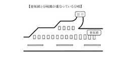
その一方、「太破線」は上記のように高速道路の出口や入口付近で本線車線と区切っているだけでなく、図20のように「太破線」が登坂路(登坂区間)を表示していて且つその登坂路(登坂区間)が分岐部と重なっている場合、および図21のように「太破線」が減速帯を表示していて且つその減速帯が分岐部と重なっている場合がある。 On the other hand, the “thick broken line” is not only separated from the main lane near the exit and entrance of the expressway as described above, but also the “thick broken line” indicates the uphill road (uphill section) as shown in FIG. In addition, when the uphill road (uphill section) overlaps the branch portion, and as shown in FIG. 21, the “thick broken line” may indicate a deceleration zone and the deceleration zone may overlap the branch portion. .
そのため、図20および図21のような分岐部において、先の第1の実施の形態のような走行車線推定や車線変更判断を行った場合には、実際の走行車線位置とは異なった分岐判断をしてしまうおそれがある。 Therefore, in the branching section as shown in FIG. 20 and FIG. 21, when the traveling lane estimation or the lane change determination as in the first embodiment is performed, the branching determination is different from the actual traveling lane position. There is a risk of doing.
そこで、この第2の実施の形態では、上記のように分岐部と登坂路(登坂区間)あるいは減速帯とが重なっている分岐部の形状(分岐形状)を特定して、その形状に合わせた自車走行車線推定と車線変更判断を行うことで、自車両Cの本線から出口車線への車線変更を的確に判定できるようにしたものである。 Therefore, in the second embodiment, as described above, the shape (branch shape) of the branch portion where the branch portion and the uphill road (uphill section) or the deceleration zone overlap is specified and matched to the shape. By performing the own vehicle traveling lane estimation and the lane change determination, it is possible to accurately determine the lane change of the own vehicle C from the main line to the exit lane.
上記のような分岐形状の特定は、図3に示した走行車線推定装置2の分岐形状特定部15が司っている。なお、この分岐形状特定部15には情報記憶部としてのメモリ15aが付帯している。 The branch shape identification as described above is governed by the branch
高速道路での分岐には、図19〜21に示したようなインターチェンジ(IC)での分岐のほか、サービスエリア(SA)やパーキングエリア(PA)での分岐およびジャンクション(JCT)での分岐があり、これらの分岐の種別は例えば図22のようなかたちでナビゲーションシステム3からの情報として与えられるので、ここでは特にインターチェンジでの分岐である場合に、図19のような基本型(基本的分岐パターン)であるか、あるいは図20のような登坂路(登坂区間)型であるか、さらには図21のような減速帯型であるか、の分岐形状を分岐形状特定部15の処理にて特定することになる。 In addition to branches at interchanges (IC) as shown in FIGS. 19 to 21, branches at expressways include branches at service areas (SA) and parking areas (PA) and junctions (JCT). These branch types are given as information from the
分岐形状特定部15は、図23に示すように、ナビゲーションシステム3からの情報である自車両の現在位置の地図データのメッシュIDと、自車位置のXY座標、対象となる分岐部の上下線方向、対象となる分岐部の分岐種別、および上下線の推定区間(XY座標)の各情報に基づいて、自車前方の分岐形状を特定する。なお、基本的な処理が共通の第1の実施の形態の図7において、そのステップS1に上記地図データのメッシュIDおよび自車位置のXY座標の取得を付記してある。 As shown in FIG. 23, the branch
ここで、図4に示したナビゲーションシステム3に格納されている地図データ21は、例えば数キロメートル四方のメッシュで区切られていて、それぞれのメッシュに固有のIDが付されていることから、このIDをメッシュIDと称する。 Here, the
また、XY座標とは、上記メッシュ上でのXY座標を指す。 The XY coordinates refer to XY coordinates on the mesh.
さらに、上下線の推定区間とは、例えば図24に示すように、特定のインターチェンジを含むメッシュ上において、予めXY座標で設定してある所定距離四方の範囲Qを指す。 Furthermore, the estimated section of the upper and lower lines refers to a range Q in a predetermined distance four directions set in advance with XY coordinates on a mesh including a specific interchange, for example, as shown in FIG.
そして、インターチェンジでの分岐部のうち、図20に示した登坂路(登坂区間)型のもの、および図21に示したような減速帯型のものについて、それらの区間を図25のようなデータ構成をもって分岐形状特定部15のメモリ15aに予めメッシュIDをもって地点登録してある。 Of the branching sections at the interchange, those of the uphill road (uphill section) type shown in FIG. 20 and those of the deceleration zone type as shown in FIG. The point is registered with the mesh ID in advance in the
上記分岐形状特定部15の処理手順の詳細を図26に示す。 The details of the processing procedure of the branch
ここでは、図9に示した車線推定エリアE内に自車両Cが進入した場合に、分岐形状特定部15のメモリ15aに予め登録しておいた分岐部のメッシュIDを読み出し、その読み出したメッシュIDと図4のナビゲーションシステム3から送られてきた自車両の現在位置のメッシュIDとを比較・照合し、推定経路上の自車前方に対象となる分岐部があるか否かを特定する(図26のステップS121)。 Here, when the host vehicle C enters the lane estimation area E shown in FIG. 9, the mesh ID of the branching part registered in advance in the
自車前方に対象となる分岐部がある場合、つまり予め登録しておいた分岐部のメッシュIDと現在位置のメッシュIDが一致した場合には、次のステップS122において対象分岐フラグをONにセットし、不一致の場合にはステップS123にて対象分岐フラグをOFFにして処理を終わる。 If there is a target branch portion ahead of the host vehicle, that is, if the mesh ID of the branch portion registered in advance matches the mesh ID of the current position, the target branch flag is set to ON in the next step S122. If they do not match, the target branch flag is turned off in step S123, and the process ends.
次いで、図24に示したインターチェンジでの分岐部において上下線(上り車線と下り車線)の誤判定を防止するため、ステップS124のように自車位置が図24の上下線の推定区間Qに進入した場合に限り、ステップS126以降にて上下線の判定を行い、そうでない場合にはステップS125にて推定区間フラグをOFFして処理を終わる。 Next, in order to prevent misjudgment of the upper and lower lines (up lane and down lane) at the intersection at the interchange shown in FIG. 24, the vehicle position enters the estimated section Q of the upper and lower lines in FIG. 24 as in step S124. Only in the case where the upper and lower lines are determined after step S126, the estimated section flag is turned off in step S125, and the process ends.
ステップS124において自車位置が図24の上下線の推定区間Qに進入した場合には、ステップS126にて推定区間フラグをONにセットした上で、ステップS127にて自車位置のXY座標を所定時間サンプリングし、自車両Cの走行軌跡を特定するべく、その自車位置のXY座標の増減度を演算する。 If the vehicle position has entered the estimated section Q of the vertical line in FIG. 24 in step S124, the estimated section flag is set to ON in step S126, and then the XY coordinates of the vehicle position are set in advance in step S127. Time sampling is performed, and the degree of increase or decrease in the XY coordinates of the vehicle position is calculated in order to specify the travel locus of the vehicle C.
そして、ステップS128において、自車両の走行軌跡、つまり自車位置のXY座標の増減度と対象となる分岐部のXY座標の増減度とが一致した場合、ステップS129のように分岐形状特定部15のメモリ15aに登録されている分岐部と自車前方の分岐部とが一致したと判断する。つまり、自車前方にある分岐部は、図20に示したような登坂路(登坂区間)型のものであると特定されるか、または図21に示したような減速帯型のものであると特定されることになる。 In step S128, when the travel locus of the host vehicle, that is, the increase / decrease degree of the XY coordinates of the host vehicle position coincides with the increase / decrease degree of the XY coordinates of the target branch part, the branch
他方、双方の増減度が一致しない場合には、ステップS130のように分岐形状特定部15のメモリ15aに登録されている分岐部と自車前方の分岐部とが一致しないと判断する。つまり、分岐部が図19に示したような基本型のものである場合がこれに該当することになる。 On the other hand, when the degree of increase / decrease does not match, it is determined that the branch part registered in the
このような処理は、特定の分岐部において上下線での分岐形状が同じとは限らないため、先ず自車両の進行方向を決定した上で、図25のように予め登録されている分岐部の上下線の方向と照合し、合致した場合のみ対象となる分岐部が自車両前方にあるものと推定するものである。 Since such a process does not necessarily have the same bifurcation shape on the upper and lower lines in a specific bifurcation part, after first determining the traveling direction of the host vehicle, the pre-registered bifurcation part as shown in FIG. It collates with the direction of the vertical line, and it is estimated that the target branching part is in front of the host vehicle only when it matches.
このような分岐形状特定部15での判定結果は、図3の走行車線推定装置2内の各部のほか、CANライン5経由にて図5の車両制御装置4等に出力される。 The determination result in the branch
以上により、図3の走行車線推定装置2では、インターチェンジにおける自車両前方の分岐部が図19のような基本型であるか、あるいは図20のような登坂路(登坂区間)型のものであるか、さらにはまた図21のような減速帯型のものであるか、が特定できたことになる。 As described above, in the driving
そして、図27に示したように、分岐部のそれぞれの形状に応じて、以降の走行車線推定処理および車線変更判断処理が実行されることになる。 Then, as shown in FIG. 27, the following travel lane estimation process and lane change determination process are executed in accordance with the shape of each branch portion.
ここで、図27のステップS141のように分岐形状が基本型(通常パターン)のものである場合には、先の第1の実施の形態と同様に図15の処理が実行される(ステップS142)。また、図27のステップS143のように分岐形状が登坂路型のものである場合には、後述するように当該登坂路型に応じた車線変更推定処理および車線変更判断処理が実行される(ステップS144)。同様に、図27のステップS145のように分岐形状が減速帯型のものである場合には、後述するように当該減速帯型に応じた車線変更推定処理および車線変更判断処理が実行されることになる(ステップS146)。 Here, when the branch shape is the basic type (normal pattern) as in step S141 in FIG. 27, the processing in FIG. 15 is executed as in the first embodiment (step S142). ). In addition, when the branch shape is an uphill road type as in step S143 in FIG. 27, a lane change estimation process and a lane change determination process corresponding to the uphill road type are executed as described later (step S144). Similarly, when the branch shape is a deceleration band type as in step S145 of FIG. 27, a lane change estimation process and a lane change determination process corresponding to the deceleration band type are executed as described later. (Step S146).
図28には分岐部の形状が図20のような登坂路(登坂区間)型のものである場合の自車走行車線推定部14(図3参照)での処理手順をに示す。 FIG. 28 shows a processing procedure in the own vehicle travel lane estimation unit 14 (see FIG. 3) in the case where the shape of the branching portion is an uphill road (uphill section) type as shown in FIG.
図28のステップS151において出口車線が左方向である場合には、次のステップS152において左側の白線種別が「実線」であるか否か判定する。このステップS152での左側の白線種別が「実線」であるか否かの判定は、「左端走行車線」を走行中か否かの判定にほかならない。ステップS152において左側の白線種別が「実線」である場合には、次のステップS153に進み、右側の白線種別が「太破線」であるかどうか判定する。右側の白線種別が「太破線」である場合には、ステップS154において「左端走行車線」を走行中と判定し、右側の白線種別が「太破線」でない場合には、ステップS155において走行車線を特定できずに「不明な走行車線」を走行中と判定する。 If the exit lane is in the left direction in step S151 of FIG. 28, it is determined in the next step S152 whether or not the white line type on the left is “solid line”. The determination of whether or not the white line type on the left side in step S152 is “solid line” is nothing other than the determination of whether or not the vehicle is traveling in the “leftmost travel lane”. If the left white line type is “solid line” in step S152, the process proceeds to the next step S153 to determine whether the right white line type is “thick broken line”. If the white line type on the right side is “thick broken line”, it is determined in step S154 that the “left-end travel lane” is traveling, and if the white line type on the right side is not “thick broken line”, the travel lane is determined in step S155. It is determined that the vehicle is traveling in an “unknown travel lane” without being identified.
先のステップS152において、左側の白線種別が「実線」でない場合には、次のステップS156に進み、左側の白線種別が「太破線」であるかどうか判定する。左側の白線種別が「太破線」である場合、次のステップS157において右側の白線種別が「太破線」であるかどうか判定する。右側の白線種別が「太破線」であれば、次のステップS158において「左端走行車線」を走行中と判定し、ステップS157において右側の白線種別が「太破線」でなければ、次のステップS159において走行車線を特定できずに「不明な走行車線」を走行中と判定する。 In the previous step S152, if the left white line type is not “solid line”, the process proceeds to the next step S156 to determine whether the left white line type is “thick broken line”. If the left white line type is “thick broken line”, it is determined in the next step S157 whether the right white line type is “thick broken line”. If the white line type on the right side is “thick broken line”, it is determined in the next step S158 that the “left-end travel lane” is traveling. If the white line type on the right side is not “thick broken line” in step S157, the next step S159 is determined. It is determined that the travel lane cannot be specified and the “unknown travel lane” is traveling.
また、先のステップS156において左側の白線種別が「太破線」でない場合には、同様に次のステップS160において走行車線を特定できずに「不明な走行車線」を走行中と判定することになる。 If the white line type on the left side is not “thick broken line” in the previous step S156, it is determined in the next step S160 that the travel lane cannot be specified and the “unknown travel lane” is being traveled. .
以上のような処理は、出口車線が右側であっても基本的に同様であって、ステップS161〜ステップS171の処理が実行されることになる。 The above processing is basically the same even when the exit lane is on the right side, and the processing from step S161 to step S171 is executed.
また、図29は分岐部の形状が図21のような減速帯型のものである場合の自車走行車線推定部14(図3参照)での処理手順を示す。 FIG. 29 shows a processing procedure in the host vehicle travel lane estimation unit 14 (see FIG. 3) in the case where the shape of the branching portion is a deceleration zone type as shown in FIG.
図29のステップS181において、出口車線が左側である場合には次のステップS182に進み、左側の白線種別が「実線」であるかどうか判定する。左側の白線種別が「実線」であるかぎりはステップS183において「左端走行車線」を走行中と判定する。これに対して、左側の白線種別が「実線」でない場合には、次のステップS184において走行車線を特定できずに「不明な走行車線」を走行中と判定する。 In step S181 in FIG. 29, if the exit lane is the left side, the process proceeds to the next step S182, and it is determined whether or not the left white line type is “solid line”. As long as the left white line type is “solid line”, it is determined in step S183 that the “leftmost travel lane” is traveling. On the other hand, if the white line type on the left side is not “solid line”, it is determined in the next step S184 that the travel lane cannot be specified and the “unknown travel lane” is being traveled.
ここで、図21のような減速帯型の分岐形状の特殊性として、同図に示すように左側の実線と太破線とがいわゆる二重線のかたちで併存しているが、少なくとも左側の白線種別を「実線」として特定できれば、これをもって直ちに「左端走行車線」を走行中と判定することができる。 Here, as a special feature of the deceleration band type branch shape as shown in FIG. 21, the left solid line and the thick broken line are present in the form of a so-called double line as shown in FIG. If the type can be specified as “solid line”, it can be immediately determined that the “leftmost lane” is traveling.
このような処理は、出口車線が右方向であっても基本的には同様であって、ステップS185〜S189の処理が実行されることになる。 Such processing is basically the same even if the exit lane is in the right direction, and the processing in steps S185 to S189 is executed.
図30は分岐部の形状が登坂路型および減速帯型である場合の車線変更判断部17(図3参照)の処理手順を示す。なお、この処理は、先の図18に示した処理手順に代わるものである。 FIG. 30 shows a processing procedure of the lane change determination unit 17 (see FIG. 3) in the case where the shape of the branch portion is an uphill road type or a deceleration zone type. This process replaces the process procedure shown in FIG.
図30のステップS191において、自車位置からインターチェンジまでの距離、つまり自車位置から図9の分岐ノードP1までの距離が所定距離内となったか否かを判定し、自車両が分岐判断対象内にある場合には次のステップS192に進み、自車両が分岐判断対象内にない場合にはステップS193で処理を終わる。 In step S191 in FIG. 30, it is determined whether or not the distance from the vehicle position to the interchange, that is, the distance from the vehicle position to the branch node P1 in FIG. If YES in step S192, the flow advances to step S192. If the host vehicle is not within the branch determination target, the process ends in step S193.
ステップS192に続くステップS194では、図20,21の「出口車線の方向が左方向」か否かを判定し、「出口車線の方向が左方向」である場合には、次のステップS195において走行車線が「左端走行車線」であるか否かを判定する。「左端走行車線」を走行中であれば次にステップS196に進み、そうでない場合にはステップS197のように自車両Cはなおも「本線車線」を走行中と判定する。 In step S194 following step S192, it is determined whether the direction of the exit lane is the left direction in FIGS. 20 and 21, and if the direction of the exit lane is the left direction, the vehicle travels in the next step S195. It is determined whether or not the lane is a “leftmost travel lane”. If the vehicle is traveling in the “leftmost traveling lane”, the process proceeds to step S196. If not, the host vehicle C determines that the vehicle is still traveling in the “main lane” as in step S197.
ステップS196では「白線跨ぎ検出=ON」か否かを判定し、「白線跨ぎ検出=ON」である場合には、次のステップS198において「車線変更の方向=左」か否かを判定し、「白線跨ぎ検出=ON」でない場合には、次のステップS199において「ウインカーの方向=左」か否かを判定する。ステップS198において「車線変更の方向=左」である場合には、次のステップS200において「左側の出口車線へ車線変更」したものと判定し、「車線変更の方向=左」でない場合にはステップS201のように自車両はなおも「本線車線」を走行中と判定する。同様に、ステップS199において「ウインカーの方向=左」である場合には、次のステップS202において「左側の出口車線へ車線変更」したものと判定し、「ウインカーの方向=左」でない場合にはステップS203のように自車両はなおも「本線車線」を走行中と判定する。 In step S196, it is determined whether or not “white line crossing detection = ON”. If “white line crossing detection = ON”, it is determined in the next step S198 whether or not “lane change direction = left”. If it is not “white line straddle detection = ON”, it is determined in the next step S199 whether “the direction of the blinker = left”. If “lane change direction = left” in step S198, it is determined in the next step S200 that “lane change to left exit lane”, and if not “lane change direction = left”, step It is determined that the host vehicle is still traveling in the “main lane” as in S201. Similarly, if “the direction of the blinker = left” in step S199, it is determined that “the lane is changed to the left exit lane” in the next step S202, and if “the direction of the blinker = left” is not determined. As in step S203, it is determined that the host vehicle is still traveling in the “main lane”.
このような処理は、ステップS204のように「出口車線の方向が右方向」である場合でも基本的に同様であって、そのステップS204以降の処理が実行される。そして、図30のステップS200,S202およびステップS217,S218等のように左側または右側の出口車線に車線変更したと判断した場合に限り、先の第1の実施の形態と同様に、車線変更完了通知を運転者に対して発することになる。 Such processing is basically the same even when “the direction of the exit lane is the right direction” as in step S204, and the processing after step S204 is executed. Then, only when it is determined that the lane has been changed to the left or right exit lane as in steps S200 and S202 and steps S217 and S218 in FIG. 30, the lane change is completed as in the first embodiment. A notification will be issued to the driver.
こうした走行車線推定装置2における車線変更判断部17での処理結果は、先の第1の実施の形態と同様に、CANライン5経由にて図5の車両制御装置4に出力され、所定の車速制御、ひいては減速制御が実行されることになる。 The processing result in the lane
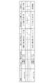
ここで、上記のようなインターチェンジにおける基本型、登坂路(登坂区間)型および減速帯型のそれぞれの分岐に際して、左端車線または右端車線の判定のための条件および車線変更の判定のための条件を整理すると図31のようになる。 Here, when branching each of the basic type, the uphill road (uphill section) type and the deceleration zone type at the interchange as described above, the conditions for determining the left end lane or the right end lane and the conditions for determining the lane change are as follows. Fig. 31 shows the result.
この第2の実施の形態によれば、インターチェンジの形状、つまり分岐の形状が基本型であるか登坂路型であるか、さらには減速帯型であるのかの違いに応じて、実質的に自車走行車線推定および車線変更判断のための条件を使い分けることにより、誤判定を未然に防止して、車両運転支援装置としての一層の信頼性向上に寄与できるようになる。 According to this second embodiment, the shape of the interchange, that is, the shape of the branch, is substantially self-dependent depending on whether the shape is a basic type, an uphill road type, or a deceleration zone type. By properly using the conditions for vehicle lane estimation and lane change determination, it is possible to prevent erroneous determination and contribute to further improvement in reliability as a vehicle driving support device.
なお、この第2の実施の形態での分岐判断は、インターチェンジ(IC)以外にも、例えば2車線または3車線以上ある本線車線が2方向またはそれ以上に分岐するジャンクション(JCT)での分岐判断にも同様に適用することができる。 In addition to the interchange (IC), for example, the branch determination in the second embodiment is a branch determination at a junction (JCT) in which a main lane having two lanes or three or more lanes branches in two or more directions. It can be similarly applied to.
図32〜34は本発明に係る車両運転支援装置の第3の実施の形態を示す図で、図5に示した車両制御装置4における車速制御自動キャンセル部36の機能に着目したものある。 FIGS. 32 to 34 are diagrams showing a third embodiment of the vehicle driving support device according to the present invention, and pay attention to the function of the vehicle speed control automatic cancel
高速道路上を走行中の分岐には、インターチェンジ(IC)やジャンクション(JCT)での分岐以外にも、サービスエリア(SA)やパーキングエリア(PA)への進入のための分岐があることは先に述べたとおりである。 In addition to branches at interchanges (IC) and junctions (JCT), there are branches for entering the service area (SA) and parking area (PA). As described in.
また、図1〜5に示した車両運転支援装置においては、いわゆる自動車速モードで走行するに際して、自車両の推定経路上において自車前方のリンクの曲率値に応じて各地点ごとの目標車速を演算し、その目標車速に応じた車速指令を図5のブレーキ制御装置37あるいはエンジン制御装置38に与えて車速を制御するものであることもまた先に述べたとおりである。 Moreover, in the vehicle driving assistance device shown in FIGS. 1 to 5, when traveling in the so-called vehicle speed mode, the target vehicle speed for each point is set according to the curvature value of the link ahead of the vehicle on the estimated route of the vehicle. As described above, the vehicle speed is calculated and given to the
この場合において、サービスエリア(SA)やパーキングエリア(PA)においては、その性質上歩行者が多いことから、自動車速モードでの走行は必ずしも好ましくない。 In this case, since there are many pedestrians in the service area (SA) and the parking area (PA), traveling in the vehicle speed mode is not always preferable.
そこで、この第3の実施の形態では、自動車速モードでの走行中において、サービスエリア(SA)やパーキングエリア(PA)へ進入した場合には、車速制御を自動的にキャンセルするようにしたものである。 Therefore, in the third embodiment, the vehicle speed control is automatically canceled when entering the service area (SA) or the parking area (PA) while traveling in the vehicle speed mode. It is.
図4のナビゲーションシステム3において、自車前方のリンク種別がサービスエリア(SA)あるいはパーキングエリア(PA)に関するものであるか否か、すなわちSAリンクであるかPAリンクであるかの情報は地図データ21から与えられる。 In the
そこで、図32のほか図33に示すように、例えば自車前方のリンク種別がSAリンクであって、且つそのSAリンクが分岐している分岐ノードP1までの距離が所定距離(例えば、0メートル)になった場合には、ナビゲーションシステム3からの情報をもとに、図5の車速制御自動キャンセル部36が自律的に車速制御のキャンセル処理を自律的に実行する(図33のステップS221〜S223)。なお、リンク種別がPAリンクの場合にも同様である。 Therefore, as shown in FIG. 33 in addition to FIG. 32, for example, the link type in front of the host vehicle is an SA link, and the distance to the branch node P1 where the SA link branches is a predetermined distance (for example, 0 meter). ), The vehicle speed control
これにより、サービスエリア(SA)あるいはパーキングエリア(PA)での走行中の安全性確保の上で一段と好ましいものとなる。 Thereby, it becomes much more preferable in ensuring safety during traveling in the service area (SA) or the parking area (PA).
ここで、上記のような車速制御の自動キャンセル機能に代えて、次のような処理形態とすることもできる。 Here, instead of the automatic cancel function of the vehicle speed control as described above, the following processing mode can be adopted.
すなわち、従来の一部のナビゲーションシステムにおいては、例えば図34に示すようなサービスエリア(SA)に関して、第1分岐点である分岐ノードP1よりも先の第2分岐点(分岐ノード)P2以降では、それぞれのSAリンクは全て直線相当の曲率値のものとして扱われている。そのため、サービスエリア(SA)内での走行に際して、上記のようなリンクの曲率値に基づいた車速制御は不可能となる。 That is, in some conventional navigation systems, for example, with respect to the service area (SA) as shown in FIG. 34, the second branch point (branch node) P2 after the branch node P1 that is the first branch point is used. Each SA link is treated as having a curvature value equivalent to a straight line. Therefore, when traveling in the service area (SA), vehicle speed control based on the curvature value of the link as described above is impossible.
そこで、図4に示したナビゲーションシステム3側でのリンク識別機能を使って、リンク種別がSAリンクであるか否かを判断する。そして、リンク種別がSAリンクである場合には、そのナビゲーションシステム3のSA速度司令部31の機能として、そのSAリンクが付帯している分岐ノードについて所定の曲率値を生成させ、これを速度指令として図5の車速司令部3に直接付与するものとする。なお、ここに言う所定の曲率値とは、自車両を安全な速度まで減速させるのに必要な曲率値で、経験的に予め設定しておくものとする。 Therefore, the link identification function on the
これにより、分岐ノードP1から第2分岐ノードP2までは地図データ上のリンク形状から曲率値を演算してその曲率値に応じた車速制御を行う一方、第2分岐ノードP2からSAリンクの終端までは上記のような特殊な曲率値に基づいた車速制御を行うことになる。 Thereby, from the branch node P1 to the second branch node P2, the curvature value is calculated from the link shape on the map data and the vehicle speed control is performed according to the curvature value, while from the second branch node P2 to the end of the SA link. Performs vehicle speed control based on the special curvature values as described above.
この場合にも、サービスエリア(SA)やパーキングエリア(PA)に進入したときに、自車両を安全な速度まで減速させることができ、安全性確保の上で好ましいものとなる。
なお、この実施例においては、通行区分、白線種別等の日本の道路事情に合わせて説明したが、本発明はこれに限らず適用可能である。具体的には、諸外国の道路事情に合わせて白線種別等のデータを変更することで対応可能である。Also in this case, when entering the service area (SA) or the parking area (PA), the host vehicle can be decelerated to a safe speed, which is preferable for ensuring safety.
In this embodiment, the description has been made in accordance with Japanese road conditions such as traffic classification and white line type, but the present invention is not limited to this and can be applied. Specifically, it can be handled by changing the data such as the type of white line according to the road conditions in other countries.
1…路面状態検出装置
2…走行車線推定装置
3…ナビゲーションシステム
4…車両制御装置
6…リアカメラ(撮像部)
8…白線種別認識部(白線パターン認識部)
9…白線種別記憶部(白線パターン記憶部)
10…白線種別推定部(白線パターン推定部)
11…白線跨ぎ検出部
14…自車走行車線推定部
15…分岐形状特定部
16…車両運動検出部
17…車線変更判断部
21…地図データ
23…HMI部(告知部)
37…ブレーキ制御装置
38…エンジン制御装置
C…自車両DESCRIPTION OF
8 ... White line type recognition unit (white line pattern recognition unit)
9. White line type storage unit (white line pattern storage unit)
10 ... White line type estimation unit (white line pattern estimation unit)
DESCRIPTION OF
37 ...
Claims (5)
Translated fromJapaneseこの撮像部が捉えた画像に基づいて自車両の現在の走行車線を区分する白線の種別を認識する白線種別認識部と、
前記白線種別認識部で認識された白線種別を記憶する白線種別記憶部と、
自車両の現在の走行車線を推定する車線推定エリアで前記白線種別認識部による白線種別の認識ができないときに前記車線推定エリアよりも手前で前記白線種別認識部により認識されて前記白線種別記憶部に記憶されている白線種別を自車両の現在の走行車線を区分する白線種別として推定する白線種別推定部と、
前記白線種別推定部で推定された白線種別に基づいて車両制御を行う車両制御部と、
前記白線種別認識部で認識された白線種別に基づいて自車両の現在の走行車線を推定する自車走行車線推定部と、
外部からの情報に基づいて自車両の前方の道路の分岐の形状を特定する分岐形状特定部と、
前記分岐形状特定部で特定された分岐の形状と、前記自車走行車線推定部で推定された走行車線、および前記白線種別認識部で認識された白線種別に基づいて、自車両が本線から分岐路側へ車線変更をしたか否かを判定する車線変更判断部と、
を備えていて、
前記分岐形状特定部で特定された分岐の形状が、本線の減速帯における走行車線の両側、及び、本線と分岐路との間が太破線の白線で区切られている第3のパターンである場合に、前記自車走行車線推定部は下記(オ)の機能を、前記車線変更判断部は下記(カ)の機能を、それぞれに発揮するものであることを特徴とする車両運転支援装置。
(オ)前記白線種別認識部での白線種別の識別結果として自車両の左側が実線と認識したときに、当該自車両が左端車線走行中と推定し、自車両の右端が実線と認識したときに、右端車線走行中と推定すること。
(カ)端車線走行特定中において自車両が実線を跨いだときに当該自車両が車線変更したと判定すること。An imaging unit that is mounted on the host vehicle and images a road surface on which the host vehicle travels;
A white line type recognizing unit for recognizing the type of the white line that divides the current traveling lane of the host vehicle based on the image captured by the imaging unit;
A white line type storage unit that stores the white line type recognized by the white line type recognition unit;
When the white line type recognition unit cannot recognize the white line type in the lane estimation area for estimating the current traveling lane of the host vehicle, the white line type storage unit is recognized by the white line type recognition unit before the lane estimation area. A white line type estimation unit for estimating a white line type stored in the vehicle as a white line type for classifying a current traveling lane of the host vehicle;
A vehicle control unit that performs vehicle control based on the white line type estimated by the white line type estimation unit;
A host vehicle travel lane estimation unit that estimates a current travel lane of the host vehicle based on the white line type recognized by the white line type recognition unit;
A branch shape identifying unit that identifies the shape of the branch of the road ahead of the host vehicle based on information from the outside,
Based on the shape of the branch specified by the branch shape specifying unit, the travel lane estimated by the host vehicle travel lane estimation unit, and the white line type recognized by the white line type recognition unit, the host vehicle branches from the main line. A lane change determination unit that determines whether or not a lane change has been made to the roadside;
With
When the shape of the branch specified by the branch shape specifying partis a third pattern in whichthe both sides of the traveling lane in the main line deceleration zone and the white line between the main line and the branch road are separated by a thick broken line. In addition, the vehicle driving lane estimation unit performs the following function (e), and the lane change determination unit performs the following function (f).
(E) When the left side of the vehicle is recognized as a solid line as a white line type identification result in the white line type recognition unit, the vehicle is estimated to be traveling in the left lane, and the right end of the vehicle is recognized as a solid line Estimate that you are driving in the rightmost lane.
(F) Determining that the host vehicle has changed lanes when the host vehicle straddles a solid line while specifying end-lane travel.
この撮像部が捉えた画像に基づいて自車両の現在の走行車線を区分する白線の種別を認識する白線種別認識部と、
前記白線種別認識部で認識された白線種別を記憶する白線種別記憶部と、
自車両の現在の走行車線を推定する車線推定エリアで前記白線種別認識部による白線種別の認識ができないときに前記車線推定エリアよりも手前で前記白線種別認識部により認識されて前記白線種別記憶部に記憶されている白線種別を自車両の現在の走行車線を区分する白線種別として推定する白線種別推定部と、
前記白線種別推定部で推定された白線種別に基づいて車両制御を行う車両制御部と、
前記白線種別認識部で認識された白線種別に基づいて自車両の現在の走行車線を推定する自車走行車線推定部と、
外部からの情報に基づいて自車両の前方の道路の分岐の形状を特定する分岐形状特定部と、
前記分岐形状特定部で特定された分岐の形状と、前記自車走行車線推定部で推定された走行車線、および前記白線種別認識部で認識された白線種別に基づいて、自車両が本線から分岐路側へ車線変更をしたか否かを判定する車線変更判断部と、
を備えていて、
前記分岐形状特定部で特定された分岐の形状が、本線と分岐路との間が太破線の白線で区切られている第1のパターンである場合に、前記自車走行車線推定部は下記(ア)の機能を、前記車線変更判断部は下記(イ)の機能を、
前記分岐形状特定部で特定された分岐の形状が、本線と登坂路との間、及び登坂路と分岐路との間が太破線の白線で区切られている第2のパターンである場合に、前記自車走行車線推定部は下記(ウ)の機能を、前記車線変更判断部は下記(エ)の機能を、
前記分岐形状特定部で特定された分岐の形状が、本線の減速帯における走行車線の両側、及び、本線と分岐路との間が太破線の白線で区切られている第3のパターンである場合に、前記自車走行車線推定部は下記(オ)の機能を、前記車線変更判断部は下記(カ)の機能を、
それぞれに発揮するものであることを特徴とする車両運転支援装置。
(ア)前記白線種別認識部での白線種別の識別結果として自車両の左側が実線または太破線と認識したときに、当該自車両が左端車線走行中と推定し、自車両の右側が実線または太破線と認識したときに当該自車両が右端車線走行中と推定すること。
(イ)端車線走行特定中において自車両が太破線を跨いだときに当該自車両が車線変更したと判定すること。
(ウ)前記白線種別認識部での白線種別の識別結果として自車両の左側が実線で且つ右側が太破線と認識したとき、または両方が太破線と認識したときに、自車両が左端車線走行中と推定し、自車両の右側が実線で且つ左側が太破線と認識したとき、または両方が太破線と認識したときに、右端車線走行中と推定すること。
(エ)端車線走行特定中において自車両が太破線を跨いだときに当該自車両が車線変更したと判定すること。
(オ)前記白線種別認識部での白線種別の識別結果として自車両の左側が実線と認識したときに、当該自車両が左端車線走行中と推定し、自車両の右端が実線と認識したときに、右端車線走行中と推定すること。
(カ)端車線走行特定中において自車両が実線を跨いだときに当該自車両が車線変更したと判定すること。An imaging unit that is mounted on the host vehicle and images a road surface on which the host vehicle travels;
A white line type recognizing unit for recognizing the type of the white line that divides the current traveling lane of the host vehicle based on the image captured by the imaging unit;
A white line type storage unit that stores the white line type recognized by the white line type recognition unit;
When the white line type recognition unit cannot recognize the white line type in the lane estimation area for estimating the current traveling lane of the host vehicle, the white line type storage unit is recognized by the white line type recognition unit before the lane estimation area. A white line type estimation unit for estimating a white line type stored in the vehicle as a white line type for classifying a current traveling lane of the host vehicle;
A vehicle control unit that performs vehicle control based on the white line type estimated by the white line type estimation unit;
A host vehicle travel lane estimation unit that estimates a current travel lane of the host vehicle based on the white line type recognized by the white line type recognition unit;
A branch shape identifying unit that identifies the shape of the branch of the road ahead of the host vehicle based on information from the outside,
Based on the shape of the branch specified by the branch shape specifying unit, the travel lane estimated by the host vehicle travel lane estimation unit, and the white line type recognized by the white line type recognition unit, the host vehicle branches from the main line. A lane change determination unit that determines whether or not a lane change has been made to the roadside;
With
When the shape of the branch specified by the branch shape specifying unitis a first pattern in which amain line and a branch road are separated by a thick dashed white line, the host vehicle traveling lane estimation unit is The function of (a), the lane change determination unit has the function of (a) below,
When the shape of the branch specified by the branch shape specifying unitis the second pattern in whichthe main line and the uphill road are separated by a white line of a thick broken line between the uphill road and the branch road , The own vehicle travel lane estimation unit has the following function (c), the lane change determination unit has the following function (d),
When the shape of the branch specified by the branch shape specifying partis a third pattern in whichthe both sides of the traveling lane in the main line deceleration zone and the white line between the main line and the branch road are separated by a thick broken line. In addition, the vehicle lane estimation unit has the following function (e), the lane change determination unit has the following function (f),
A vehicle driving support device characterized by being exhibited by each.
(A) When the left side of the own vehicle is recognized as a solid line or a thick broken line as a white line type identification result by the white line type recognition unit, the own vehicle is estimated to be traveling in the left lane, and the right side of the own vehicle is a solid line or Estimating that the vehicle is traveling in the right lane when it is recognized as a thick broken line.
(B) When the host vehicle crosses the thick broken line while the end lane driving is specified, it is determined that the host vehicle has changed lanes.
(C) When the left side of the host vehicle is recognized as a solid line and the right side as a thick broken line, or both are recognized as a thick broken line as a result of white line type identification by the white line type recognition unit, the host vehicle travels in the left lane. Estimating that the vehicle is traveling in the right lane when the right side of the host vehicle is recognized as a solid line and the left side is recognized as a thick broken line, or when both are recognized as a thick broken line.
(D) It is determined that the host vehicle has changed lanes when the host vehicle crosses the thick broken line while the end lane driving is specified.
(E) When the left side of the vehicle is recognized as a solid line as a white line type identification result in the white line type recognition unit, the vehicle is estimated to be traveling in the left lane, and the right end of the vehicle is recognized as a solid line Estimate that you are driving in the rightmost lane.
(F) Determining that the host vehicle has changed lanes when the host vehicle straddles a solid line while specifying end-lane travel.
前記自車走行車線推定部による走行車線の推定は、前記分岐部よりも手前位置に予め設定された推定開始位置に自車両が到達した時点で開始することを特徴とする車両運転支援装置。The vehicle driving support device according to claim2 ,
The driving lane estimation by the own vehicle traveling lane estimation unit is started when the host vehicle reaches an estimation start position preset in front of the branching unit.
前記自車走行車線推定部による推定結果と自車両の方向指示器による指示方向とに基づいて自車両が車線変更することを推定する車線変更判断部を備えていることを特徴とする車両運転支援装置。The vehicle driving support device according to claim2 ,
A vehicle driving support comprising a lane change determination unit that estimates that the host vehicle changes lanes based on a result of estimation by the host vehicle traveling lane estimation unit and a direction indicated by a direction indicator of the host vehicle. apparatus.
このカメラが撮像した画像に基づいて自車両の左右に存在する路面上の白線パターンを認識する白線パターン認識部と、
前記白線パターン認識部での認識結果に基づいて自車両の走行車線を推定する自車走行車線推定部と、
前記白線パターン認識部で認識された白線パターンを記憶する白線パターン記憶部と、
自車両の現在の走行車線を推定する車線推定エリアで前記白線パターン認識部によって白線パターンが認識できないときに前記車線推定エリアよりも手前で前記白線パターン認識部により認識されて前記白線パターン記憶部に記憶されている白線パターンを現在の自車両の左右に存在する白線パターンとして推定する白線パターン推定部と、
前記白線パターン認識部による認識結果と前記白線パターン推定部による推定結果に基づいて車両制御を行う車両制御部と、
地図データをもとに自車両の前方の道路の分岐の存在とその形状を特定する分岐形状特定部と、
前記分岐形状特定部で特定された分岐の形状と、前記自車走行車線推定部で推定された走行車線、および前記白線パターン認識部で認識された白線パターンに基づいて、自車両が本線から分岐路側へ車線変更をしたか否かを判定する車線変更判断部と、
少なくとも車線変更判断部による車線変更判断後にアクチュエータを作動させて自車両を減速制御する車両制御装置と、
を備えていて、
前記車両制御部は、前記白線パターン認識部により白線パターンが認識されている場合はその認識された白線パターンに基づいて車両制御を実行する一方、白線パターンが認識できない場合は前記白線パターン推定部で推定された白線パターンに基づいて車両制御を実行し、
前記分岐形状特定部で特定された分岐の形状が、本線と分岐路との間が太破線の白線で区切られている第1のパターンである場合に、前記自車走行車線推定部は下記(ア)の機能を、前記車線変更判断部は下記(イ)の機能を、
前記分岐形状特定部で特定された分岐の形状が、本線と登坂路との間、及び登坂路と分岐路との間が太破線の白線で区切られている第2のパターンである場合に、前記自車走行車線推定部は下記(ウ)の機能を、前記車線変更判断部は下記(エ)の機能を、
前記分岐形状特定部で特定された分岐の形状が、本線の減速帯における走行車線の両側、及び、本線と分岐路との間が太破線の白線で区切られている第3のパターンである場合に、前記自車走行車線推定部は下記(オ)の機能を、前記車線変更判断部は下記(カ)の機能を、それぞれに発揮するものであることを特徴とする車両運転支援装置。
(ア)前記白線パターン認識部での白線パターンの識別結果として自車両の左側が実線または太破線と認識したときに当該自車両が左端車線走行中と推定し、自車両の右側が実線または太破線と認識したときに当該自車両が右端車線走行中と推定すること。
(イ)端車線走行特定中において自車両が太破線を跨いだときに当該自車両が車線変更したと判定すること。
(ウ)前記白線パターン認識部での白線パターンの識別結果として自車両の左側が実線で且つ右側が太破線と認識したとき、または両方が太破線と認識したときに、自車両が左端車線走行中と推定し、自車両の右側が実線で且つ左側が太破線と認識したとき、または両方が太破線と認識したときに、右端車線走行中と推定すること。
(エ)端車線走行特定中において自車両が太破線を跨いだときに当該自車両が車線変更したと判定すること。
(オ)前記白線パターン認識部での白線パターンの識別結果として自車両の左側が実線と認識したときに、当該自車両が左端車線走行中と推定し、自車両の右端が実線と認識したときに、右端車線走行中と推定すること。
(カ)端車線走行特定中において自車両が実線を跨いだときに当該自車両が車線変更したと判定すること。A camera mounted on the host vehicle that images the road surface on which the host vehicle travels;
A white line pattern recognition unit for recognizing a white line pattern on the road surface existing on the left and right of the host vehicle based on an image captured by the camera;
A host vehicle travel lane estimation unit that estimates a travel lane of the host vehicle based on a recognition result in the white line pattern recognition unit;
A white line pattern storage unit for storing a white line pattern recognized by the white line pattern recognition unit;
When a white line pattern cannot be recognized by the white line pattern recognition unit in the lane estimation area for estimating the current traveling lane of the host vehicle, the white line pattern recognition unit recognizes the white line pattern before the lane estimation area and stores the white line pattern in the white line pattern storage unit. A white line pattern estimation unit that estimates the stored white line patterns as white line patterns present on the left and right sides of the current vehicle;
A vehicle control unit that performs vehicle control based on the recognition result by the white line pattern recognition unit and the estimation result by the white line pattern estimation unit;
A branch shape identifying unit that identifies the presence and shape of a branch of a road ahead of the host vehicle based on map data;
Based on the shape of the branch specified by the branch shape specifying unit, the travel lane estimated by the host vehicle travel lane estimation unit, and the white line pattern recognized by the white line pattern recognition unit, the host vehicle branches from the main line. A lane change determination unit that determines whether or not a lane change has been made to the roadside;
A vehicle control device that operates the actuator after the lane change determination by at least the lane change determination unit to control the deceleration of the host vehicle;
With
When the white line pattern is recognized by the white line pattern recognition unit, the vehicle control unit performs vehicle control based on the recognized white line pattern, and when the white line pattern cannot be recognized, the white line pattern estimation unit Perform vehicle control based on the estimated white line pattern,
When the shape of the branch specified by the branch shape specifying unit is a first pattern in which a main line and a branch road are separated by a thick dashed white line, the host vehicle traveling lane estimation unit is The function of (a), the lane change determination unit has the function of (a) below,
When the shape of the branch specified by the branch shape specifying unit is the second pattern in which the main line and the uphill road are separated by a white line of a thick broken line between the uphill road and the branch road, The own vehicle travel lane estimation unit has the following function (c), the lane change determination unit has the following function (d),
When the shape of the branch specified by the branch shape specifying partis a third pattern in whichthe both sides of the traveling lane in the main line deceleration zone and the white line between the main line and the branch road are separated by a thick broken line. In addition, the vehicle driving lane estimation unit performs the following function (e), and the lane change determination unit performs the following function (f).
(A) When the left side of the host vehicle is recognized as a solid line or a thick broken line as a white line pattern identification result in the white line pattern recognition unit, it is estimated that the host vehicle is traveling in the left lane, and the right side of the host vehicle is a solid line or a thick line. Estimating that the subject vehicle is traveling in the right lane when recognized as a broken line.
(B) When the host vehicle crosses the thick broken line while the end lane driving is specified, it is determined that the host vehicle has changed lanes.
(C) When the left side of the host vehicle is recognized as a solid line and the right side as a thick broken line as a result of white line pattern recognition by the white line pattern recognition unit, or when both are recognized as a thick broken line, the host vehicle travels in the left lane. Estimating that the vehicle is traveling in the right lane when the right side of the host vehicle is recognized as a solid line and the left side is recognized as a thick broken line, or when both are recognized as a thick broken line.
(D) It is determined that the host vehicle has changed lanes when the host vehicle crosses the thick broken line while the end lane driving is specified.
(E) When the left side of the host vehicle is recognized as a solid line as a white linepattern identification result by the white linepattern recognition unit, the host vehicle is estimated to be traveling in the left lane, and the right end of the host vehicle is recognized as a solid line Estimate that you are driving in the rightmost lane.
(F) Determining that the host vehicle has changed lanes when the host vehicle straddles a solid line while specifying end-lane travel.
Priority Applications (2)
| Application Number | Priority Date | Filing Date | Title |
|---|---|---|---|
| JP2009071559AJP5066123B2 (en) | 2009-03-24 | 2009-03-24 | Vehicle driving support device |
| US12/651,769US8385600B2 (en) | 2009-03-24 | 2010-01-04 | Vehicle driving assistance apparatus |
Applications Claiming Priority (1)
| Application Number | Priority Date | Filing Date | Title |
|---|---|---|---|
| JP2009071559AJP5066123B2 (en) | 2009-03-24 | 2009-03-24 | Vehicle driving support device |
Publications (2)
| Publication Number | Publication Date |
|---|---|
| JP2010221859A JP2010221859A (en) | 2010-10-07 |
| JP5066123B2true JP5066123B2 (en) | 2012-11-07 |
Family
ID=42784299
Family Applications (1)
| Application Number | Title | Priority Date | Filing Date |
|---|---|---|---|
| JP2009071559AExpired - Fee RelatedJP5066123B2 (en) | 2009-03-24 | 2009-03-24 | Vehicle driving support device |
Country Status (2)
| Country | Link |
|---|---|
| US (1) | US8385600B2 (en) |
| JP (1) | JP5066123B2 (en) |
Families Citing this family (82)
| Publication number | Priority date | Publication date | Assignee | Title |
|---|---|---|---|---|
| JP4720383B2 (en)* | 2005-09-01 | 2011-07-13 | トヨタ自動車株式会社 | Vehicle control device |
| DE102010052129A1 (en)* | 2010-11-22 | 2012-06-06 | GM Global Technology Operations LLC | Method for operating a motor vehicle and motor vehicle |
| DE102010052128A1 (en) | 2010-11-22 | 2012-05-24 | GM Global Technology Operations LLC | Method for operating a motor vehicle and motor vehicle |
| JP5281664B2 (en)* | 2011-02-23 | 2013-09-04 | クラリオン株式会社 | Lane departure warning device and lane departure warning system |
| US9542846B2 (en)* | 2011-02-28 | 2017-01-10 | GM Global Technology Operations LLC | Redundant lane sensing systems for fault-tolerant vehicular lateral controller |
| US20120245817A1 (en)* | 2011-03-23 | 2012-09-27 | Tk Holdings Inc. | Driver assistance system |
| US9041789B2 (en) | 2011-03-25 | 2015-05-26 | Tk Holdings Inc. | System and method for determining driver alertness |
| ES2402422B1 (en)* | 2011-09-07 | 2014-03-11 | Manuel MUÑOZ SÁIZ | AUTOMATIC DRIVING SYSTEM AND IMPROVED VELOCITY ZONE WARNING SYSTEMS FOR IMPROVED VEHICLES |
| US9187117B2 (en) | 2012-01-17 | 2015-11-17 | Ford Global Technologies, Llc | Autonomous lane control system |
| US8504233B1 (en) | 2012-04-27 | 2013-08-06 | Google Inc. | Safely navigating on roads through maintaining safe distance from other vehicles |
| US8521352B1 (en)* | 2012-05-07 | 2013-08-27 | Google Inc. | Controlling a vehicle having inadequate map data |
| US8494716B1 (en)* | 2012-06-04 | 2013-07-23 | GM Global Technology Operations LLC | Lane keeping system using rear camera |
| US9230556B2 (en) | 2012-06-05 | 2016-01-05 | Apple Inc. | Voice instructions during navigation |
| US10176633B2 (en) | 2012-06-05 | 2019-01-08 | Apple Inc. | Integrated mapping and navigation application |
| US9997069B2 (en) | 2012-06-05 | 2018-06-12 | Apple Inc. | Context-aware voice guidance |
| US9886794B2 (en) | 2012-06-05 | 2018-02-06 | Apple Inc. | Problem reporting in maps |
| US9418672B2 (en) | 2012-06-05 | 2016-08-16 | Apple Inc. | Navigation application with adaptive instruction text |
| US8965696B2 (en) | 2012-06-05 | 2015-02-24 | Apple Inc. | Providing navigation instructions while operating navigation application in background |
| US9482296B2 (en) | 2012-06-05 | 2016-11-01 | Apple Inc. | Rendering road signs during navigation |
| US8983778B2 (en)* | 2012-06-05 | 2015-03-17 | Apple Inc. | Generation of intersection information by a mapping service |
| US9159153B2 (en) | 2012-06-05 | 2015-10-13 | Apple Inc. | Method, system and apparatus for providing visual feedback of a map view change |
| KR101252015B1 (en)* | 2012-08-16 | 2013-04-09 | 주식회사 피엘케이 테크놀로지 | Navigation system for judging route change of vehicle |
| JP5931691B2 (en)* | 2012-10-24 | 2016-06-08 | アルパイン株式会社 | White line detection device and white line detection method |
| US9063548B1 (en) | 2012-12-19 | 2015-06-23 | Google Inc. | Use of previous detections for lane marker detection |
| US9081385B1 (en) | 2012-12-21 | 2015-07-14 | Google Inc. | Lane boundary detection using images |
| DE102013208758A1 (en)* | 2013-05-13 | 2014-11-13 | Robert Bosch Gmbh | Method and device for operating a vehicle |
| DE102013210923A1 (en)* | 2013-06-12 | 2014-12-18 | Robert Bosch Gmbh | Predictive control of a motor vehicle |
| JP6154213B2 (en)* | 2013-06-28 | 2017-06-28 | 株式会社Soken | Road surface information acquisition device |
| KR101782496B1 (en)* | 2013-08-21 | 2017-09-27 | 주식회사 만도 | Back-sideways alarming system of vehicle and alarming control method of the same |
| US9435653B2 (en)* | 2013-09-17 | 2016-09-06 | GM Global Technology Operations LLC | Sensor-aided vehicle positioning system |
| DE102013220905A1 (en)* | 2013-10-15 | 2015-04-16 | Continental Automotive Gmbh | Method for guiding a motor vehicle and motor vehicle for carrying out the method |
| KR101502510B1 (en)* | 2013-11-26 | 2015-03-13 | 현대모비스 주식회사 | Apparatus and method for controlling lane keeping of vehicle |
| KR20150062490A (en)* | 2013-11-29 | 2015-06-08 | 주식회사 만도 | Device and Method for Controlling Vehicle Speed |
| EP3514032B1 (en) | 2013-12-04 | 2024-02-07 | Mobileye Vision Technologies Ltd. | Adjusting velocity of a vehicle for a curve |
| US9666069B2 (en)* | 2014-02-14 | 2017-05-30 | Ford Global Technologies, Llc | Autonomous vehicle handling and performance adjustment |
| US9460624B2 (en) | 2014-05-06 | 2016-10-04 | Toyota Motor Engineering & Manufacturing North America, Inc. | Method and apparatus for determining lane identification in a roadway |
| JP2016018256A (en) | 2014-07-04 | 2016-02-01 | 株式会社デンソー | Branch-merger determination device |
| US9321461B1 (en) | 2014-08-29 | 2016-04-26 | Google Inc. | Change detection using curve alignment |
| JP6390276B2 (en)* | 2014-09-02 | 2018-09-19 | アイシン・エィ・ダブリュ株式会社 | Automatic driving support system, automatic driving support method, and computer program |
| JP6328254B2 (en)* | 2014-09-05 | 2018-05-23 | 三菱電機株式会社 | Automated traveling management system, server, and automated traveling management method |
| JP6354542B2 (en)* | 2014-11-26 | 2018-07-11 | 株式会社デンソー | Automatic vehicle driving system |
| JP6363516B2 (en)* | 2015-01-21 | 2018-07-25 | 株式会社デンソー | Vehicle travel control device |
| JP6344275B2 (en)* | 2015-03-18 | 2018-06-20 | トヨタ自動車株式会社 | Vehicle control device |
| JP6046190B2 (en)* | 2015-03-31 | 2016-12-14 | 本田技研工業株式会社 | Driving assistance device |
| JP6491929B2 (en) | 2015-03-31 | 2019-03-27 | アイシン・エィ・ダブリュ株式会社 | Automatic driving support system, automatic driving support method, and computer program |
| JP6559453B2 (en)* | 2015-03-31 | 2019-08-14 | アイシン・エィ・ダブリュ株式会社 | Automatic driving support system, automatic driving support method, and computer program |
| JP6465730B2 (en) | 2015-04-21 | 2019-02-06 | アルパイン株式会社 | Electronic device, traveling lane identification system, and traveling lane identification method |
| BR112018001879B1 (en)* | 2015-07-27 | 2022-07-19 | Nissan Motor Co., Ltd | ROUTE GUIDANCE DEVICE AND ROUTE GUIDANCE METHOD |
| US9829888B2 (en)* | 2015-11-17 | 2017-11-28 | Ford Global Technologies, Llc | Distinguishing lane markings for a vehicle to follow |
| US10369994B2 (en) | 2016-07-20 | 2019-08-06 | Ford Global Technologies, Llc | Rear camera stub detection |
| JP6293213B2 (en)* | 2016-08-01 | 2018-03-14 | 三菱電機株式会社 | Lane marking detection correction device, lane marking detection correction method, and automatic driving system |
| CN106323289A (en)* | 2016-08-23 | 2017-01-11 | 北京小米移动软件有限公司 | Method of and devices for balance car control |
| JP6250120B1 (en)* | 2016-09-12 | 2017-12-20 | 三菱電機株式会社 | Lane maintenance support device and lane maintenance support method |
| US10093315B2 (en)* | 2016-09-19 | 2018-10-09 | Ford Global Technologies, Llc | Target vehicle deselection |
| JP6649512B2 (en)* | 2016-12-28 | 2020-02-19 | 本田技研工業株式会社 | Vehicle control system, vehicle control method, and vehicle control program |
| CN108734955B (en) | 2017-04-14 | 2021-06-11 | 腾讯科技(深圳)有限公司 | Method and device for predicting road condition state |
| KR20190012370A (en)* | 2017-07-27 | 2019-02-11 | 삼성에스디에스 주식회사 | Method and Apparatus for lane change support |
| JP7080091B2 (en)* | 2018-04-02 | 2022-06-03 | 本田技研工業株式会社 | Vehicle control devices, vehicle control methods, and programs |
| US11069245B2 (en)* | 2018-05-14 | 2021-07-20 | Toyota Jidosha Kabushiki Kaisha | Lane change timing indicator |
| JP6828714B2 (en) | 2018-05-30 | 2021-02-10 | 株式会社Soken | Self-position estimator |
| US11016999B2 (en) | 2018-08-31 | 2021-05-25 | Here Global B.V. | Use of geographic database comprising lane level information for traffic parameter prediction |
| US12055401B1 (en) | 2018-08-31 | 2024-08-06 | Here Global B.V. | Use of geographic database comprising lane level information for traffic parameter prediction |
| US11035686B2 (en)* | 2018-08-31 | 2021-06-15 | Here Global B.V. | Use of geographic database comprising lane level information for traffic parameter prediction |
| JP7087896B2 (en) | 2018-10-01 | 2022-06-21 | 株式会社Soken | Driving lane estimation device, driving lane estimation method, and control program |
| KR102115915B1 (en)* | 2018-10-08 | 2020-05-27 | 주식회사 만도 | Apparatus and method for determining distortion in road lane recognition |
| KR102540937B1 (en)* | 2018-12-14 | 2023-06-08 | 현대자동차주식회사 | Driver assistance apparatus and method for operating thereof |
| JP7077967B2 (en) | 2019-01-10 | 2022-05-31 | 株式会社Soken | Driving lane estimation device, driving lane estimation method, and control program |
| JP7274327B2 (en)* | 2019-03-28 | 2023-05-16 | 株式会社Subaru | Automated driving support device |
| CN110414328A (en)* | 2019-06-19 | 2019-11-05 | 上海眼控科技股份有限公司 | A kind of overtaking other vehicles illegal automatic auditing method for piggybacking based on deep learning |
| JP7462642B2 (en)* | 2019-07-23 | 2024-04-05 | 本田技研工業株式会社 | Autonomous work machine, control device, control method for autonomous work machine, operation method of control device, and program |
| CN113022573B (en) | 2019-12-06 | 2022-11-04 | 华为技术有限公司 | Road structure detection method and device |
| WO2021187384A1 (en)* | 2020-03-16 | 2021-09-23 | 株式会社デンソー | Traveling track generation device and traveling track generation method |
| DE112020007074T5 (en)* | 2020-04-13 | 2023-03-02 | Mitsubishi Electric Corporation | LANE DETECTION DEVICE AND LANE DETECTION METHOD |
| JP7513433B2 (en)* | 2020-06-10 | 2024-07-09 | 株式会社Subaru | Driver Assistance Systems |
| JP2022182094A (en)* | 2021-05-27 | 2022-12-08 | 本田技研工業株式会社 | MOBILE BODY CONTROL DEVICE, MOBILE BODY CONTROL METHOD, AND PROGRAM |
| CN113232658B (en)* | 2021-06-28 | 2022-06-28 | 驭势(上海)汽车科技有限公司 | Vehicle positioning method and device, electronic equipment and storage medium |
| KR102403324B1 (en)* | 2021-09-24 | 2022-05-31 | 주식회사 빅드림 | Method for coding education based on pattern sensing and apparatus for performing the method |
| JP7348942B2 (en) | 2021-12-07 | 2023-09-21 | 本田技研工業株式会社 | Vehicle control device, vehicle control method, and program |
| IT202200004946A1 (en)* | 2022-03-15 | 2023-09-15 | Ferrari Spa | METHOD OF CONTROL OF A VEHICLE WITH THE RECOGNITION OF AN EXIT INTENTION |
| IT202200004943A1 (en)* | 2022-03-15 | 2023-09-15 | Ferrari Spa | METHOD OF CONTROL OF A VEHICLE WITH THE RECOGNITION OF AN EXIT INTENTION |
| CN118843571A (en)* | 2022-03-18 | 2024-10-25 | 日产自动车株式会社 | Vehicle travel control method and vehicle travel control device |
| JP7427699B2 (en)* | 2022-03-25 | 2024-02-05 | 本田技研工業株式会社 | Driving support device, vehicle, driving support method, storage medium and program |
Family Cites Families (13)
| Publication number | Priority date | Publication date | Assignee | Title |
|---|---|---|---|---|
| JP4329088B2 (en)* | 1998-02-18 | 2009-09-09 | 株式会社エクォス・リサーチ | Vehicle control device |
| US6577334B1 (en)* | 1998-02-18 | 2003-06-10 | Kabushikikaisha Equos Research | Vehicle control |
| JP2001289654A (en)* | 2000-04-11 | 2001-10-19 | Equos Research Co Ltd | NAVIGATION DEVICE, NAVIGATION DEVICE CONTROL METHOD, AND RECORDING MEDIUM RECORDING ITS PROGRAM |
| JP3626733B2 (en)* | 2002-03-01 | 2005-03-09 | 三菱電機株式会社 | Lane recognition image processing apparatus and program for executing the processing |
| JP3861836B2 (en)* | 2003-04-01 | 2006-12-27 | 株式会社デンソー | Vehicle guidance system using vehicle guidance tags |
| JP4055650B2 (en)* | 2003-05-16 | 2008-03-05 | 株式会社デンソー | Branch approach estimation device, vehicle speed control device, and program |
| JP2006184105A (en)* | 2004-12-27 | 2006-07-13 | Aisin Aw Co Ltd | Navigation apparatus |
| JP4321821B2 (en)* | 2005-01-28 | 2009-08-26 | アイシン・エィ・ダブリュ株式会社 | Image recognition apparatus and image recognition method |
| JP4665622B2 (en)* | 2005-06-22 | 2011-04-06 | 日産自動車株式会社 | Own vehicle position detection device, navigation device, and deceleration control device |
| JP4654796B2 (en) | 2005-06-29 | 2011-03-23 | トヨタ自動車株式会社 | Vehicle driving support device |
| JP2007240316A (en)* | 2006-03-08 | 2007-09-20 | Matsushita Electric Ind Co Ltd | In-vehicle ranging device |
| JP4878256B2 (en)* | 2006-10-18 | 2012-02-15 | 株式会社日立製作所 | Branch line recognition device and car navigation system |
| JP4861850B2 (en)* | 2007-02-13 | 2012-01-25 | アイシン・エィ・ダブリュ株式会社 | Lane determination device and lane determination method |
- 2009
- 2009-03-24JPJP2009071559Apatent/JP5066123B2/ennot_activeExpired - Fee Related
- 2010
- 2010-01-04USUS12/651,769patent/US8385600B2/ennot_activeExpired - Fee Related
Also Published As
| Publication number | Publication date |
|---|---|
| US20100246889A1 (en) | 2010-09-30 |
| JP2010221859A (en) | 2010-10-07 |
| US8385600B2 (en) | 2013-02-26 |
Similar Documents
| Publication | Publication Date | Title |
|---|---|---|
| JP5066123B2 (en) | Vehicle driving support device | |
| US8265869B2 (en) | Vehicle navigation apparatus and vehicle navigation program | |
| US10703362B2 (en) | Autonomous driving autonomous system, automated driving assistance method, and computer program | |
| CN103303306B (en) | The unsafe condition just occurring is made warning method to vehicle driver | |
| CN101246010B (en) | Lane determining device, method, and program | |
| RU2742213C1 (en) | Method to control information on lanes, method of traffic control and device for control of information on lanes | |
| JP2018197964A (en) | Control method of vehicle, and device thereof | |
| CN114286774B (en) | Detecting Potentially Occluded Objects for Autonomous Vehicles | |
| JP2005107693A (en) | Device and program for detecting travel position of one's own vehicle | |
| JP2006309445A (en) | Driving-support device | |
| JP2011118603A (en) | Vehicle controller | |
| JP4614098B2 (en) | Peripheral situation recognition device and method | |
| JP7182623B2 (en) | Driving assistance for automobiles when approaching a speed barrier | |
| JP4979644B2 (en) | Navigation device and vehicle travel safety device | |
| CN111989727A (en) | Vehicle driving support method and vehicle driving support device | |
| JP4806045B2 (en) | Lane recognition device | |
| JP4591777B2 (en) | Self-recognition system | |
| JP4692831B2 (en) | Peripheral situation recognition device and method | |
| JP5637381B2 (en) | Road node position management system, road node position management method, and road node position management program | |
| JP2019020128A (en) | Method for generating travel route of driving assisted vehicle and travel route generator | |
| JP5208016B2 (en) | Merge / Exit Determination Device and Merge / Exit Determination Program | |
| JP5656066B2 (en) | Road node position management system, road node position management method, and road node position management program | |
| CN113276885A (en) | Control method and control device for unmanned vehicle and unmanned vehicle | |
| CN118419048A (en) | Abnormality detection system and abnormality detection method | |
| JP6232883B2 (en) | Own vehicle position recognition device |
Legal Events
| Date | Code | Title | Description |
|---|---|---|---|
| A621 | Written request for application examination | Free format text:JAPANESE INTERMEDIATE CODE: A621 Effective date:20100715 | |
| RD03 | Notification of appointment of power of attorney | Free format text:JAPANESE INTERMEDIATE CODE: A7423 Effective date:20100907 | |
| RD04 | Notification of resignation of power of attorney | Free format text:JAPANESE INTERMEDIATE CODE: A7424 Effective date:20101005 | |
| A131 | Notification of reasons for refusal | Free format text:JAPANESE INTERMEDIATE CODE: A131 Effective date:20101214 | |
| A521 | Request for written amendment filed | Free format text:JAPANESE INTERMEDIATE CODE: A523 Effective date:20110214 | |
| A131 | Notification of reasons for refusal | Free format text:JAPANESE INTERMEDIATE CODE: A131 Effective date:20111122 | |
| A521 | Request for written amendment filed | Free format text:JAPANESE INTERMEDIATE CODE: A523 Effective date:20120120 | |
| A02 | Decision of refusal | Free format text:JAPANESE INTERMEDIATE CODE: A02 Effective date:20120327 | |
| A521 | Request for written amendment filed | Free format text:JAPANESE INTERMEDIATE CODE: A523 Effective date:20120626 | |
| A911 | Transfer to examiner for re-examination before appeal (zenchi) | Free format text:JAPANESE INTERMEDIATE CODE: A911 Effective date:20120703 | |
| TRDD | Decision of grant or rejection written | ||
| A01 | Written decision to grant a patent or to grant a registration (utility model) | Free format text:JAPANESE INTERMEDIATE CODE: A01 Effective date:20120807 | |
| A01 | Written decision to grant a patent or to grant a registration (utility model) | Free format text:JAPANESE INTERMEDIATE CODE: A01 | |
| A61 | First payment of annual fees (during grant procedure) | Free format text:JAPANESE INTERMEDIATE CODE: A61 Effective date:20120810 | |
| R150 | Certificate of patent or registration of utility model | Ref document number:5066123 Country of ref document:JP Free format text:JAPANESE INTERMEDIATE CODE: R150 Free format text:JAPANESE INTERMEDIATE CODE: R150 | |
| FPAY | Renewal fee payment (event date is renewal date of database) | Free format text:PAYMENT UNTIL: 20150817 Year of fee payment:3 | |
| S533 | Written request for registration of change of name | Free format text:JAPANESE INTERMEDIATE CODE: R313533 | |
| R350 | Written notification of registration of transfer | Free format text:JAPANESE INTERMEDIATE CODE: R350 | |
| LAPS | Cancellation because of no payment of annual fees |