JP5063864B2 - Device for removing complete vascular occlusion under monitoring by intravascular ultrasound - Google Patents
Device for removing complete vascular occlusion under monitoring by intravascular ultrasoundDownload PDFInfo
- Publication number
- JP5063864B2 JP5063864B2JP2005098548AJP2005098548AJP5063864B2JP 5063864 B2JP5063864 B2JP 5063864B2JP 2005098548 AJP2005098548 AJP 2005098548AJP 2005098548 AJP2005098548 AJP 2005098548AJP 5063864 B2JP5063864 B2JP 5063864B2
- Authority
- JP
- Japan
- Prior art keywords
- catheter
- ivus
- cto
- forceps
- sensor
- Prior art date
- Legal status (The legal status is an assumption and is not a legal conclusion. Google has not performed a legal analysis and makes no representation as to the accuracy of the status listed.)
- Expired - Fee Related
Links
- 238000002608intravascular ultrasoundMethods0.000titleclaimsdescription63
- 238000012544monitoring processMethods0.000titleclaimsdescription7
- 206010053648Vascular occlusionDiseases0.000titleclaimsdescription6
- 208000021331vascular occlusion diseaseDiseases0.000titleclaimsdescription6
- 210000004204blood vesselAnatomy0.000claimsdescription10
- 239000002872contrast mediaSubstances0.000claimsdescription10
- 230000001684chronic effectEffects0.000claimsdescription8
- 238000004140cleaningMethods0.000claimsdescription4
- 230000024883vasodilationEffects0.000claimsdescription2
- 239000012530fluidSubstances0.000claims1
- 208000031481Pathologic ConstrictionDiseases0.000description13
- 230000036262stenosisEffects0.000description13
- 208000037804stenosisDiseases0.000description13
- 239000002131composite materialSubstances0.000description8
- 238000000034methodMethods0.000description5
- 230000006378damageEffects0.000description4
- 230000008901benefitEffects0.000description3
- 210000004351coronary vesselAnatomy0.000description3
- 230000008878couplingEffects0.000description3
- 238000010168coupling processMethods0.000description3
- 238000005859coupling reactionMethods0.000description3
- 238000010586diagramMethods0.000description3
- 239000007788liquidSubstances0.000description3
- 208000027418Wounds and injuryDiseases0.000description2
- 238000003384imaging methodMethods0.000description2
- 208000014674injuryDiseases0.000description2
- 230000009467reductionEffects0.000description2
- 238000001356surgical procedureMethods0.000description2
- 230000002792vascularEffects0.000description2
- 208000019553vascular diseaseDiseases0.000description2
- 238000005406washingMethods0.000description2
- 240000005020Acaciella glaucaSpecies0.000description1
- 206010003210ArteriosclerosisDiseases0.000description1
- 206010057469Vascular stenosisDiseases0.000description1
- 230000000172allergic effectEffects0.000description1
- 238000002583angiographyMethods0.000description1
- 208000011775arteriosclerosis diseaseDiseases0.000description1
- 208000010668atopic eczemaDiseases0.000description1
- 230000000740bleeding effectEffects0.000description1
- 230000008021depositionEffects0.000description1
- 238000006073displacement reactionMethods0.000description1
- 239000003814drugSubstances0.000description1
- 229940079593drugDrugs0.000description1
- 230000006870functionEffects0.000description1
- 238000003780insertionMethods0.000description1
- 230000037431insertionEffects0.000description1
- 238000013147laser angioplastyMethods0.000description1
- 230000003902lesionEffects0.000description1
- 239000003550markerSubstances0.000description1
- 208000010125myocardial infarctionDiseases0.000description1
- 238000007781pre-processingMethods0.000description1
- 230000008569processEffects0.000description1
- 238000012545processingMethods0.000description1
- 238000011002quantificationMethods0.000description1
- 235000003499redwoodNutrition0.000description1
- 238000002560therapeutic procedureMethods0.000description1
Images


Classifications
- A—HUMAN NECESSITIES
- A61—MEDICAL OR VETERINARY SCIENCE; HYGIENE
- A61B—DIAGNOSIS; SURGERY; IDENTIFICATION
- A61B8/00—Diagnosis using ultrasonic, sonic or infrasonic waves
- A61B8/12—Diagnosis using ultrasonic, sonic or infrasonic waves in body cavities or body tracts, e.g. by using catheters
- A—HUMAN NECESSITIES
- A61—MEDICAL OR VETERINARY SCIENCE; HYGIENE
- A61B—DIAGNOSIS; SURGERY; IDENTIFICATION
- A61B17/00—Surgical instruments, devices or methods
- A61B17/22—Implements for squeezing-off ulcers or the like on inner organs of the body; Implements for scraping-out cavities of body organs, e.g. bones; for invasive removal or destruction of calculus using mechanical vibrations; for removing obstructions in blood vessels, not otherwise provided for
- A—HUMAN NECESSITIES
- A61—MEDICAL OR VETERINARY SCIENCE; HYGIENE
- A61B—DIAGNOSIS; SURGERY; IDENTIFICATION
- A61B17/00—Surgical instruments, devices or methods
- A61B17/28—Surgical forceps
- A61B17/29—Forceps for use in minimally invasive surgery
- A—HUMAN NECESSITIES
- A61—MEDICAL OR VETERINARY SCIENCE; HYGIENE
- A61B—DIAGNOSIS; SURGERY; IDENTIFICATION
- A61B17/00—Surgical instruments, devices or methods
- A61B17/32—Surgical cutting instruments
- A61B2017/320044—Blunt dissectors
- A—HUMAN NECESSITIES
- A61—MEDICAL OR VETERINARY SCIENCE; HYGIENE
- A61B—DIAGNOSIS; SURGERY; IDENTIFICATION
- A61B90/00—Instruments, implements or accessories specially adapted for surgery or diagnosis and not covered by any of the groups A61B1/00 - A61B50/00, e.g. for luxation treatment or for protecting wound edges
- A61B90/36—Image-producing devices or illumination devices not otherwise provided for
- A61B90/37—Surgical systems with images on a monitor during operation
- A61B2090/378—Surgical systems with images on a monitor during operation using ultrasound
- A61B2090/3782—Surgical systems with images on a monitor during operation using ultrasound transmitter or receiver in catheter or minimal invasive instrument
- A61B2090/3784—Surgical systems with images on a monitor during operation using ultrasound transmitter or receiver in catheter or minimal invasive instrument both receiver and transmitter being in the instrument or receiver being also transmitter
Landscapes
- Health & Medical Sciences (AREA)
- Life Sciences & Earth Sciences (AREA)
- Surgery (AREA)
- Molecular Biology (AREA)
- General Health & Medical Sciences (AREA)
- Veterinary Medicine (AREA)
- Engineering & Computer Science (AREA)
- Biomedical Technology (AREA)
- Heart & Thoracic Surgery (AREA)
- Medical Informatics (AREA)
- Public Health (AREA)
- Animal Behavior & Ethology (AREA)
- Nuclear Medicine, Radiotherapy & Molecular Imaging (AREA)
- Orthopedic Medicine & Surgery (AREA)
- Vascular Medicine (AREA)
- Physics & Mathematics (AREA)
- Biophysics (AREA)
- Pathology (AREA)
- Radiology & Medical Imaging (AREA)
- Ultra Sonic Daignosis Equipment (AREA)
- Apparatus For Radiation Diagnosis (AREA)
- Surgical Instruments (AREA)
Description
Translated fromJapanese本発明は、前端範囲に配置された拡張鉗子を備えた慢性完全閉塞カテーテル(CTOカテーテル)により血管内超音波法(intravascukar ultrasound;IVUS)による監視の下に完全血管閉塞を除去するための装置に関する。 The present invention relates to an apparatus for removing complete vascular occlusion under monitoring by intravascular ultrasound (IVUS) with a chronic total occlusion catheter (CTO catheter) with dilatation forceps placed in the front end region. .
死という結果をともなう最も頻発する病気の一つは血管の病気、特に心筋梗塞である。これは冠状血管の病気(動脈硬化症)によって引き起こされる。冠状血管が沈着(動脈硬化プラーク)によって詰まった状態となる。特に重い場合には冠状血管の完全閉塞、所謂"慢性完全閉塞"(Chronic Total Coronary Occlusion、又はChronic Total Occlusion;CTO)が生じる。この閉塞は過去において大概はバイパス手術によってしか治療できなかった。最近では、特に長い狭窄(>2cm)且つ完全閉塞の場合、プラークの除去を行なうのに、付加的にレーザ血管形成術(PTLA)が確立された。しかしながら、PTLAの場合、血管壁の出血、損傷または穿孔/切開の形での負傷の些細ではない危険が存在する。なお、慢性完全閉塞は慢性完全閉塞病変とも呼ばれている。 One of the most frequent illnesses that result in death is vascular disease, particularly myocardial infarction. This is caused by coronary vascular disease (arteriosclerosis). Coronary blood vessels become clogged by deposition (arteriosclerotic plaque). Particularly severe cases result in complete occlusion of the coronary blood vessels, the so-called “chronic total occlusion” (Chronic Total Occlusion) or CTO. In the past, this occlusion was mostly treatable by bypass surgery. Recently, laser angioplasty (PTLA) has additionally been established to perform plaque removal, especially in cases of long stenosis (> 2 cm) and complete occlusion. However, in the case of PTLA there is a non-trivial risk of injury in the form of blood vessel wall bleeding, injury or perforation / incision. Chronic total occlusion is also called chronic total occlusion lesion.
米国食品医薬品局(FDA)によって2002年2月にCTO除去のための新しい器具、所謂"慢性完全閉塞カテーテル(CTOカテーテル)"が認可された。この装置は拡張鉗子に似た動作をし、冠状血管内のプラークを少しずつ押し崩し、血管閉塞全体の段階的除去を可能にする。CTO除去のためのこのようなCTOカテーテルは、「血管閉塞治療用カテーテルシステムの手動操作器」や「血管閉塞治療法」として文献に開示されている(例えば、特許文献1、特許文献2(特に図18)参照)。製品としては米国カリフォルニア州Redwood CityのLuMend社の「Frontrunner CTO Catheter」が知られている。 In February 2002, the US Food and Drug Administration (FDA) approved a new device for CTO removal, the so-called “chronic total occlusion catheter (CTO catheter)”. This device acts like an expansion forceps and gradually collapses the plaque in the coronary vessel, allowing gradual removal of the entire vascular occlusion. Such CTO catheters for CTO removal are disclosed in the literature as “manual operating devices for catheter systems for vascular occlusion treatment” and “vascular occlusion treatment methods” (for example,
CTOカテーテルによるインターベンション治療は血管撮影システムによるX線監視下で行なわれる。この方法の欠点は、冠状血管が2次元で表示され、X線画像において本来の狭窄しか表示されないことにある。血管をはっきりと見えるようにするためには、付加的に造影剤が冠状血管内に注入されなければならない。若干の患者において造影剤アレルギーが知られており、あるいは突然の熱感を訴える患者もいる。その上に、医師は術中にプラークと血管壁とをほとんど区別することができない。それによって、誤った部位で「拡張鉗子」が当てがわれて血管壁の損傷を生じる危険が増大する。 Intervention treatment with a CTO catheter is performed under X-ray monitoring by an angiography system. The disadvantage of this method is that the coronary vessels are displayed in two dimensions and only the original stenosis is displayed in the X-ray image. In order to make the blood vessels clearly visible, an additional contrast agent must be injected into the coronary blood vessels. Some patients are known to be allergic to contrast agents, or some have complained of sudden heat. In addition, doctors can hardly distinguish between plaque and blood vessel wall during surgery. This increases the risk that the “expansion forceps” will be applied at the wrong site and cause damage to the vessel wall.
血管内への血管内超音波カテーテル(IVUSカテーテル)の導入は画像形成情報を改善したが、しかし比較的高価なカテーテルが患者に挿入されなければならず、しかもCTOカテーテルの挿入前に血管から引き抜かれなければならない欠点を有する。このようなIVUSシステムは公知である(例えば、特許文献3および特許文献4参照)。
本発明の課題は、場合によっては血管拡張中にもインターベンション治療部位の直接観察を種々のカテーテルの面倒な交換なしに実施することができる簡単に取扱い可能な最適な装置を使用できるように、冒頭に述べた装置を構成することにある。 The object of the present invention is to be able to use an optimal device that can be easily handled, allowing direct observation of the interventional treatment site, even during vasodilation, without cumbersome replacement of various catheters. It is to constitute the apparatus described at the beginning.
この課題の解決のために、本発明によれば、CTOカテーテルがIVUSカテーテルと一体化されて1つのユニットに組み込まれる。特にCTOカテーテルのカテーテル管内に、拡張鉗子のための機械的操作線のほかに、回転するIVUS信号線が配置され、IVUS信号線は、カテーテル管の周囲を取巻く環状窓の内側において拡張鉗子の直ぐ背後に、又は拡張鉗子の開口を通して移動可能であり拡張鉗子の直ぐ前方に配置可能であるIVUSセンサまで導かれている。IVUS信号線の回転は、IVUSセンサの必要な回転とは違って強制的ではないが、望ましいことである。 To solve this problem, according to the present invention, the CTO catheter is integrated with the IVUS catheter and integrated into one unit. In particular, in the catheter tube of the CTO catheter, a rotating IVUS signal line is arranged in addition to the mechanical operation line for the expansion forceps, and the IVUS signal line is located immediately inside the annular forceps around the circumference of the catheter tube. It is led to an IVUS sensor that can be moved behind or through the opening of the expansion forceps and positioned immediately in front of the expansion forceps. The rotation of the IVUS signal line is desirable, although not mandatory, unlike the required rotation of the IVUS sensor.
本発明によって、CTOカテーテルとこのCTOカテーテル内に組み込まれて一体化されたIVUSカテーテルとから成る1つのユニットが構成され、このユニットは完全な血管狭窄を開けるための最適なシステムである。本発明による大きな利点は、方法ステップの低減および使用されるカテーテルの低減並びに適用されるX線の低減にある。IVUSシステムの画像は、特にプラークおよび血管壁の近傍範囲における重要な付加的な医療情報を高い分解能で供給する。従って、その都度プラークを識別して、正しい部位でCTO拡張鉗子によりプラークの除去を行い、引続いて即座に結果をチェックすることができ、しかも造影剤またはX線による患者の不必要に大きな負担なし行なうことができる。それに加えて、血管壁の損傷の危険が低減される。 According to the present invention, a single unit comprising a CTO catheter and an IVUS catheter integrated and integrated within the CTO catheter is constructed, which is the optimal system for opening a complete vascular stenosis. A great advantage with the present invention lies in the reduction of method steps and the number of catheters used and the reduction of applied X-rays. Images of the IVUS system provide important additional medical information with high resolution, especially in the vicinity of plaque and vessel walls. Therefore, each time the plaque is identified, the plaque can be removed with a CTO extension forceps at the correct site, and the result can be checked immediately, and the patient is unnecessarily burdened with contrast medium or X-rays. Can be done without. In addition, the risk of vascular wall damage is reduced.
本発明の実施態様においては、IVUS信号線がIVUSセンサのための中空の可撓性駆動軸の内部にある。 In an embodiment of the invention, the IVUS signal line is inside a hollow flexible drive shaft for the IVUS sensor.
拡張鉗子の前方へのIVUSセンサの配置は治療の開始前に完全狭窄の直接観察を可能にするが、拡張鉗子の前方にIVUSセンサを配置するために、IVUSセンサのための駆動軸が、駆動軸内を延びるIVUS信号線と共に、既に述べた拡張鉗子の中心における開口を通して移動可能にカテーテル管に支承されているとよい。完全狭窄の最初の観察後にIVUSセンサがCTOカテーテルのカテーテル管の中に引き戻されるので、その後に拡張鉗子が使用可能になる。引続いて、IVUSセンサを再び押し出して作業結果を観察することができるので、損傷のないように大切に扱いながら段階的に完全狭窄の開通を達成することができる。 The placement of the IVUS sensor in front of the expansion forceps allows direct observation of the complete stenosis before the start of treatment, but in order to place the IVUS sensor in front of the expansion forceps, the drive shaft for the IVUS sensor is driven Along with the IVUS signal line extending in the axis, the catheter tube may be supported so as to be movable through the opening at the center of the expansion forceps described above. After the first observation of complete stenosis, the IVUS sensor is pulled back into the catheter tube of the CTO catheter so that dilatation forceps can subsequently be used. Subsequently, the IVUS sensor can be pushed out again and the work result can be observed, so that the complete stenosis can be opened step by step while being handled carefully so as not to be damaged.
回転するIVUSセンサを備えた上述の装置の代わりに、参考例によれば、CTOカテーテルの可撓性のカテーテル管内に拡張鉗子ための機械的操作線のほかにIVUS信号線が配置され、IVUS信号線は、拡張鉗子の直ぐ背後においてカテーテル管内に組み込まれている複数の超音波変換器からなるセンサアレイまで導かれている。個々の超音波変換器が同時に送信器および受信器として働くような環状のセンサアレイを設けることによって、回転するIVUSセンサを必要とせず、それにともなって駆動装置も必要としない。このようにして、複合カテーテルの該当部分を固定側の供給装置に接続するための回転カップリングも省略される。Instead of the above-described device with a rotating IVUS sensor, according to thereference example , an IVUS signal line is arranged in the flexible catheter tube of the CTO catheter in addition to the mechanical operating line for the expansion forceps, and the IVUS signal The line is led to a sensor array consisting of a plurality of ultrasonic transducers incorporated in the catheter tube just behind the expansion forceps. By providing an annular sensor array in which the individual ultrasonic transducers simultaneously act as transmitters and receivers, no rotating IVUS sensors are required and thus no drive is required. In this way, the rotary coupling for connecting the relevant part of the composite catheter to the supply device on the fixed side is also omitted.
CTO・IVUS複合カテーテルのこの装置は、IVUSセンサが拡張鉗子に対して先行するように配置される装置に適している。なぜならば、この場合にはIVUSセンサのための回転する駆動軸が必要でなく、その代わりに血管壁の走査のずれはセンサアレイの超音波変換器の時間をずらした制御によって得られるからである。 This device of a CTO / IVUS combined catheter is suitable for devices in which the IVUS sensor is placed in front of the expansion forceps. This is because, in this case, a rotating drive shaft for the IVUS sensor is not required, and instead the displacement of the vessel wall scan is obtained by time-shifted control of the sensor array ultrasonic transducers. .
CTOカテーテルのカテーテル管は、本発明の他の実施態様に従って、端部側に造影剤もしくは洗浄液のための入口もしくは出口を備えるとよい。 The catheter tube of the CTO catheter may be provided with an inlet or outlet for contrast agent or washing solution on the end side according to another embodiment of the present invention.
CTOカテーテルの先端範囲に配置可能な血管内磁気式ナビゲーションのための磁石のほかに、場合によってはCTOカテーテルの先端に、血管内でのカテーテルの固定および/または血管拡張に役立つ好ましくは多室構造の膨張可能なバルーンが配置されもよい。 In addition to a magnet for intravascular magnetic navigation that can be placed in the distal region of the CTO catheter, preferably at the distal end of the CTO catheter, preferably a multi-chamber structure that serves to secure and / or dilate the catheter within the blood vessel Inflatable balloons may be arranged.
更に、装置が、貫通するガイドワイヤもしくはガイドカテーテルを有することも本発明の枠内である。 It is further within the framework of the present invention that the device has a guide wire or guide catheter therethrough.
その場合に、本発明による装置の使用時における典型的な方法経過は例えば次のように展開される。 In that case, a typical process sequence during the use of the device according to the invention is developed, for example, as follows.
ガイドワイヤまたはガイドカテーテルが、場合によって造影剤を用いてX線監視の下に目標位置(狭窄)まで挿入される。 A guide wire or guide catheter is inserted to the target position (stenosis) under X-ray monitoring, optionally using a contrast agent.
CTO・IVUS複合カテーテルが、場合によって造影剤を用いてX線監視の下に目標位置(狭窄)まで挿入される。 A CTO / IVUS composite catheter is inserted to the target position (stenosis) under X-ray monitoring, optionally using a contrast agent.
所望の目標位置まで到達後、IVUS法のために洗浄液が注入され、プラークを除去すべき部位が高分解能で観察される。 After reaching the desired target position, a cleaning solution is injected for the IVUS method, and the site where plaque is to be removed is observed with high resolution.
引続いて、CTOインターベンション治療がプラークにおいて段階的に行なわれる。この際にその都度の拡張経過後に進行をIVUSによりチェックすることができる。 Subsequently, CTO interventional treatment is performed in stages on the plaque. At this time, the progress can be checked by IVUS after each expansion.
完全なインターベンション治療の終了後に完成された血管部分がもう一度IVUSでチェックされる。 After completion of the complete interventional treatment, the completed vascular part is checked again with IVUS.
本発明による装置は、既に述べたCTO・IVUS複合カテーテルのほかに、プラークの除去に用いられる一体化カテーテルの一部のためのユーザインターフェースに本発明によるカテーテルを接続するための装置を含む。IVUS画像データのための信号インターフェースユニットおよび前処理部のほかに、画像メモリを含む画像処理ユニットおよび画像表示ユニットが設けられている。勿論、電源ユニットおよびネットワークインターフェースが存在する。 In addition to the CTO / IVUS composite catheter already described, the device according to the invention includes a device for connecting the catheter according to the invention to a user interface for a part of an integrated catheter used for plaque removal. In addition to the signal interface unit and the preprocessing unit for IVUS image data, an image processing unit including an image memory and an image display unit are provided. Of course, there are power supply units and network interfaces.
IVUS画像システムは、除去すべき狭窄の定量化を可能にするために、例えばインターベンション治療の前および後における狭窄率を得るために、メニューを拡張されるとよい。更に、ユーザインターフェースは、キーボードおよび/またはバーコードもしくはマウスを介して患者データおよびカテーテルパラメータのデータを入力する入力手段を含んでいる。 The IVUS imaging system may be extended with a menu to allow quantification of the stenosis to be removed, for example to obtain the stenosis rate before and after interventional therapy. Further, the user interface includes input means for inputting patient data and catheter parameter data via a keyboard and / or bar code or mouse.
以下における図面に基づく幾つかの実施例の説明から本発明の他の利点、特徴および詳細を明らかにする。 Other advantages, features and details of the invention will become apparent from the following description of several embodiments with reference to the drawings.
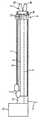
図1は慢性完全閉塞カテーテル(CTOカテーテル)を示す。 FIG. 1 shows a chronic total occlusion catheter (CTO catheter).
図2a〜2dはインターベンション治療の異なる時点でのこのようなCTOカテーテルによる完全狭窄の除去の概略説明図を示す。 Figures 2a-2d show a schematic illustration of the removal of complete stenosis with such a CTO catheter at different points in the interventional treatment.
図3は拡張鉗子の直ぐ背後に配置されたIVUSセンサを備えた本発明にるCTO・IVUS複合カテーテルの概略構成図を示す。 FIG. 3 shows a schematic configuration diagram of a CTO / IVUS composite catheter according to the present invention having an IVUS sensor disposed immediately behind an expansion forceps.
図4はCTO・IVUS複合カテーテルの参考例の概略構成図を示し、回転するIVUSセンサの代わりに1つのセンサアレイを形成する多数の超音波変換器がカテーテル管に組み込まれている。FIG. 4 shows a schematic configuration diagram ofa reference example ofaCTO / IVUS composite catheter, in which multiple ultrasonic transducers forming one sensor array are incorporated in a catheter tube instead of a rotating IVUS sensor.
図1は、可撓性のカテーテル管1を有するCTOカテーテルを示し、カテーテル管1の先端には拡張鉗子2が配置されている。拡張鉗子2は同様に鉗子状のハンドグリップ3により操作することができる。従って、拡張鉗子2は、鉗子脚2a,2bの図2a,2dに示されている閉じた位置から外側へ広げることができ、これは図2b,2cから認識できる。これらの図2a〜2dはプラーク4の開通の異なる段階を示す。 FIG. 1 shows a CTO catheter having a
図3には、狭窄除去に使用される本発明によるIVUS監視機能内蔵のCTOカテーテルの構成が概略的な原理図で示されている。可撓性のカテーテル管1の内部には操作用ハンドグリップ3から拡張鉗子2へ通じている操作線5,6が設けられており、一方の操作線は鉗子脚2a,2bの開脚運動を生じさせ、他方の操作線は鉗子脚2a,2bの閉脚運動を生じさせる。これは可撓性のロッドによって行なうことができるが、あるいは簡単に引張ワイヤによっても行なうこともできる。可撓性のカテーテル管1内には、操作線5,6のほかに、中空の可撓性駆動軸7がその中に配置されたIVUSセンサ9用の信号線8と共に配置されている。IVUSセンサ9は、拡張鉗子2の直ぐ背後においてカテーテル管1の超音波透過性の環状窓10の内側に配置されている。11は造影剤および洗浄液の接続管である。造影剤および洗浄液は、カテーテル管1を通って環状窓10の範囲に配置された図示されていない出口に向かってポンプで送り出される。機械的接続システム12を介して、複合カテーテルはIVUSシステムのための信号インターフェースおよび駆動ユニットに接続されている。これらのインターフェースおよび駆動ユニットはボックス13によって簡略化されて示されている。この機械的接続システム12は接続のための回転カップリング14を有する。 FIG. 3 shows a schematic principle diagram of the configuration of a CTO catheter with an IVUS monitoring function according to the present invention used for removing stenosis. Inside the
図4は、回転するIVUSセンサ9の代わりに、カテーテル管1の周囲に等間隔に分布して配置された多数の超音波変換器16によって構成されたセンサアレイ9'が使用される参考例を示す。この構成は、回転する部分が発生せず、従って可撓性駆動軸7が、回転可能な装置およびIVUS信号線8のそれに対応して回転可能な接続部と同様に、必要とされない利点を有する。FIG. 4 shows areference example in which a
本発明は図示の実施例に限定されない。例えば、カテーテル先端もしくはカテーテルに永久磁石または電磁石を備えた磁気式ナビゲーションも可能である。これらの磁石および磁石位置は画像内に表示されない。更に、カテーテル先端をインターベンション治療中に所望の位置にもたらしもしくは保持するために、そして場合によっては付加的に拡張バルーンとしても使用するために、膨張可能な、しかも好ましくは多室構造のバルーンを先端範囲に取付けることもできる。このバルーンも図に示されていない。更に、公知のX線マーカをカテーテルシャフトに設けてもよく、しかも勿論ガイドワイヤのための開口を設けてもよい。完全狭窄の除去のためのCTO・IVUS複合カテーテルの本発明により提案された解決策は冠状血管についての使用に限らず、基本的には全ての種類の体内血管に適している。 The present invention is not limited to the illustrated embodiment. For example, magnetic navigation with a permanent magnet or electromagnet at the catheter tip or catheter is also possible. These magnets and magnet positions are not displayed in the image. In addition, an inflatable and preferably multi-chamber balloon is provided for bringing or holding the catheter tip in a desired position during the interventional treatment, and optionally also for use as an expansion balloon. It can also be installed in the tip range. This balloon is also not shown in the figure. Furthermore, a known X-ray marker may be provided on the catheter shaft, and of course, an opening for the guide wire may be provided. The solution proposed by the present invention of a combined CTO / IVUS catheter for the removal of complete stenosis is not limited to use with coronary vessels, but is basically suitable for all types of body vessels.
更に、図示された実施例とは異なり、IVUSセンサを拡張鉗子に対して先行するように配置することも可能である。図3による実施例におけるように回転するIVUSセンサの押し込み可能性のほかに、IVUSセンサが同様に前方へ向かって移動可能であるが但し図4におけるようにセンサアレイとして構成されている装置を設けることもできるので、回転運動が必要というわけではない。 Furthermore, unlike the illustrated embodiment, it is also possible to place the IVUS sensor ahead of the expansion forceps. In addition to the pushability of the rotating IVUS sensor as in the embodiment according to FIG. 3, the IVUS sensor is likewise movable forward but provided with a device configured as a sensor array as in FIG. It is not necessary to have a rotational movement.
1 カテーテル管
2 拡張鉗子
2a 鉗子脚
2b 鉗子脚
3 操作用ハンドグリップ
4 プラーク
5 操作線
6 操作線
7 駆動軸
8 信号線
9 IVUSセンサ
9' センサアレイ
10 環状窓
11 造影剤および洗浄液のための接続管
12 機械的接続システム
13 IVUSシステムのための信号インターフェースおよび駆動ユニット
14 回転カップリング
16 超音波変換器
DESCRIPTION OF
Claims (5)
Translated fromJapaneseApplications Claiming Priority (2)
| Application Number | Priority Date | Filing Date | Title |
|---|---|---|---|
| DE102004015641.7 | 2004-03-31 | ||
| DE102004015641ADE102004015641B3 (en) | 2004-03-31 | 2004-03-31 | Device for elimination of complete occlusion with IVUS monitoring |
Publications (2)
| Publication Number | Publication Date |
|---|---|
| JP2005288167A JP2005288167A (en) | 2005-10-20 |
| JP5063864B2true JP5063864B2 (en) | 2012-10-31 |
Family
ID=35097185
Family Applications (1)
| Application Number | Title | Priority Date | Filing Date |
|---|---|---|---|
| JP2005098548AExpired - Fee RelatedJP5063864B2 (en) | 2004-03-31 | 2005-03-30 | Device for removing complete vascular occlusion under monitoring by intravascular ultrasound |
Country Status (3)
| Country | Link |
|---|---|
| US (1) | US7704210B2 (en) |
| JP (1) | JP5063864B2 (en) |
| DE (1) | DE102004015641B3 (en) |
Families Citing this family (10)
| Publication number | Priority date | Publication date | Assignee | Title |
|---|---|---|---|---|
| DE102005045373A1 (en) | 2005-09-22 | 2007-04-05 | Siemens Ag | catheter device |
| DE102006011255B4 (en)* | 2006-03-10 | 2012-08-02 | Siemens Ag | Multimodal imaging medical examination device |
| WO2009009802A1 (en)* | 2007-07-12 | 2009-01-15 | Volcano Corporation | Oct-ivus catheter for concurrent luminal imaging |
| DE102009014489B4 (en) | 2009-03-23 | 2011-03-10 | Siemens Aktiengesellschaft | Catheter and medical device |
| DE102009014462B4 (en) | 2009-03-23 | 2019-01-17 | Siemens Healthcare Gmbh | A blood pump, medical device, comprising a blood pump and methods for assisting the placement of a blood pump |
| DE102010007177B4 (en)* | 2010-02-08 | 2017-06-22 | Siemens Healthcare Gmbh | Display method for an image of the interior of a vessel located in front of a widening device and display device corresponding thereto |
| WO2014028770A1 (en) | 2012-08-15 | 2014-02-20 | Burdette Everette C | Mri compatible ablation catheter system incorporating directional high-intensity ultrasound for treatment |
| US11147990B2 (en)* | 2013-03-12 | 2021-10-19 | Acoustic Medsystems, Inc. | Ultrasound therapy catheter with multi-chambered balloons for transluminal longitudinal positioning |
| US20150305716A1 (en)* | 2014-04-28 | 2015-10-29 | Koninklijke Philips N.V | Ultrasound Transducer Array Apparatus and Method of Imaging Using Transducer Arrays |
| EP3307172A4 (en) | 2015-06-15 | 2019-05-22 | Sunnybrook Research Institute | INTRAVASCULAR IMAGING CATHETERS AND METHODS OF USING SAME |
Family Cites Families (18)
| Publication number | Priority date | Publication date | Assignee | Title |
|---|---|---|---|---|
| JPH04183461A (en)* | 1990-11-19 | 1992-06-30 | Aloka Co Ltd | Ultrasonic diagnostic and therapeutic device |
| JPH04347147A (en)* | 1991-05-23 | 1992-12-02 | Fujitsu Ltd | Ultrasound diagnostic equipment |
| US5865801A (en)* | 1995-07-18 | 1999-02-02 | Houser; Russell A. | Multiple compartmented balloon catheter with external pressure sensing |
| JPH09135908A (en)* | 1995-11-17 | 1997-05-27 | Aloka Co Ltd | Ultrasonic diagnosis treatment system |
| JP3126323B2 (en)* | 1996-11-01 | 2001-01-22 | 株式会社貝印刃物開発センター | Structure of the treatment section in the treatment tool for endoscope |
| US5741270A (en)* | 1997-02-28 | 1998-04-21 | Lumend, Inc. | Manual actuator for a catheter system for treating a vascular occlusion |
| US6217549B1 (en)* | 1997-02-28 | 2001-04-17 | Lumend, Inc. | Methods and apparatus for treating vascular occlusions |
| US6120516A (en)* | 1997-02-28 | 2000-09-19 | Lumend, Inc. | Method for treating vascular occlusion |
| US6508825B1 (en)* | 1997-02-28 | 2003-01-21 | Lumend, Inc. | Apparatus for treating vascular occlusions |
| US6401719B1 (en)* | 1997-09-11 | 2002-06-11 | Vnus Medical Technologies, Inc. | Method of ligating hollow anatomical structures |
| AU1927399A (en)* | 1998-01-16 | 1999-08-02 | Lumend, Inc. | Catheter apparatus for treating arterial occlusions |
| AU6279299A (en)* | 1998-10-02 | 2000-04-26 | Stereotaxis, Inc. | Magnetically navigable and/or controllable device for removing material from body lumens and cavities |
| US6911026B1 (en)* | 1999-07-12 | 2005-06-28 | Stereotaxis, Inc. | Magnetically guided atherectomy |
| US6168579B1 (en)* | 1999-08-04 | 2001-01-02 | Scimed Life Systems, Inc. | Filter flush system and methods of use |
| US7517352B2 (en)* | 2000-04-07 | 2009-04-14 | Bacchus Vascular, Inc. | Devices for percutaneous remote endarterectomy |
| JP2002136537A (en)* | 2000-11-01 | 2002-05-14 | Aloka Co Ltd | Blood vessel treatment apparatus and blood vessel treatment system |
| US20030236443A1 (en)* | 2002-04-19 | 2003-12-25 | Cespedes Eduardo Ignacio | Methods and apparatus for the identification and stabilization of vulnerable plaque |
| DE102005045071A1 (en)* | 2005-09-21 | 2007-04-12 | Siemens Ag | Catheter device with a position sensor system for the treatment of a partial and / or complete vascular occlusion under image monitoring |
- 2004
- 2004-03-31DEDE102004015641Apatent/DE102004015641B3/ennot_activeExpired - Fee Related
- 2005
- 2005-03-29USUS11/092,780patent/US7704210B2/ennot_activeExpired - Fee Related
- 2005-03-30JPJP2005098548Apatent/JP5063864B2/ennot_activeExpired - Fee Related
Also Published As
| Publication number | Publication date |
|---|---|
| JP2005288167A (en) | 2005-10-20 |
| US20050234343A1 (en) | 2005-10-20 |
| US7704210B2 (en) | 2010-04-27 |
| DE102004015641B3 (en) | 2006-03-09 |
Similar Documents
| Publication | Publication Date | Title |
|---|---|---|
| JP4817696B2 (en) | Device for performing cutting balloon intervention therapy under monitoring by intravascular ultrasound | |
| JP4850429B2 (en) | Apparatus for performing cutting balloon intervention therapy | |
| JP4993864B2 (en) | Device for performing and monitoring rotabration | |
| JP4993863B2 (en) | Device for performing and monitoring rotabration | |
| US7785261B2 (en) | Catheter device with a position sensor system for treating a vessel blockage using image monitoring | |
| US8167810B2 (en) | Catheter device for treating a blockage of a vessel | |
| US8359086B2 (en) | Device for applying and monitoring medical atherectomy | |
| US6770035B2 (en) | Ultrasound imaging guidewire with static central core and tip | |
| JP4993982B2 (en) | Catheter apparatus and treatment apparatus | |
| JP4969786B2 (en) | Device for performing and monitoring intravascular radiation therapy | |
| JP2008100055A (en) | Method and system for navigating through organ in shape of blocked tube | |
| JP5063864B2 (en) | Device for removing complete vascular occlusion under monitoring by intravascular ultrasound | |
| US20080058917A1 (en) | Catheter for removing tissue from a hollow organ | |
| JP4863639B2 (en) | A device for removing complete vascular occlusion under monitoring by optical coherence tomographic imaging | |
| CN104918652A (en) | An apparatus and method for delivery of intravascular filters | |
| US12343198B2 (en) | Delivery catheter having imaging capabilities | |
| US20180317879A1 (en) | Guarded imaging devices and methods | |
| JP2001245886A (en) | Ultrasonic echo catheter within blood vessel | |
| JP2000229083A (en) | Ultrasonic catheter | |
| JP2011136254A (en) | Ultrasonic catheter | |
| WO2024215869A1 (en) | Flush-less intravascular ultrasound technology | |
| JP2003061963A (en) | Ultrasonic catheter | |
| WO2025217396A1 (en) | Electronic architecture for intravascular ultrasound technology |
Legal Events
| Date | Code | Title | Description |
|---|---|---|---|
| A621 | Written request for application examination | Free format text:JAPANESE INTERMEDIATE CODE: A621 Effective date:20080324 | |
| A977 | Report on retrieval | Free format text:JAPANESE INTERMEDIATE CODE: A971007 Effective date:20100902 | |
| A131 | Notification of reasons for refusal | Free format text:JAPANESE INTERMEDIATE CODE: A131 Effective date:20100914 | |
| A521 | Request for written amendment filed | Free format text:JAPANESE INTERMEDIATE CODE: A523 Effective date:20101208 | |
| RD03 | Notification of appointment of power of attorney | Free format text:JAPANESE INTERMEDIATE CODE: A7423 Effective date:20101208 | |
| A02 | Decision of refusal | Free format text:JAPANESE INTERMEDIATE CODE: A02 Effective date:20110322 | |
| A521 | Request for written amendment filed | Free format text:JAPANESE INTERMEDIATE CODE: A523 Effective date:20110712 | |
| A911 | Transfer to examiner for re-examination before appeal (zenchi) | Free format text:JAPANESE INTERMEDIATE CODE: A911 Effective date:20110721 | |
| A912 | Re-examination (zenchi) completed and case transferred to appeal board | Free format text:JAPANESE INTERMEDIATE CODE: A912 Effective date:20110819 | |
| A01 | Written decision to grant a patent or to grant a registration (utility model) | Free format text:JAPANESE INTERMEDIATE CODE: A01 | |
| A61 | First payment of annual fees (during grant procedure) | Free format text:JAPANESE INTERMEDIATE CODE: A61 Effective date:20120808 | |
| R150 | Certificate of patent or registration of utility model | Ref document number:5063864 Country of ref document:JP Free format text:JAPANESE INTERMEDIATE CODE: R150 Free format text:JAPANESE INTERMEDIATE CODE: R150 | |
| FPAY | Renewal fee payment (event date is renewal date of database) | Free format text:PAYMENT UNTIL: 20150817 Year of fee payment:3 | |
| R250 | Receipt of annual fees | Free format text:JAPANESE INTERMEDIATE CODE: R250 | |
| R250 | Receipt of annual fees | Free format text:JAPANESE INTERMEDIATE CODE: R250 | |
| R250 | Receipt of annual fees | Free format text:JAPANESE INTERMEDIATE CODE: R250 | |
| R250 | Receipt of annual fees | Free format text:JAPANESE INTERMEDIATE CODE: R250 | |
| R250 | Receipt of annual fees | Free format text:JAPANESE INTERMEDIATE CODE: R250 | |
| LAPS | Cancellation because of no payment of annual fees |