JP5062155B2 - Liquid cooling jacket manufacturing method and friction stir welding method - Google Patents
Liquid cooling jacket manufacturing method and friction stir welding methodDownload PDFInfo
- Publication number
- JP5062155B2 JP5062155B2JP2008313291AJP2008313291AJP5062155B2JP 5062155 B2JP5062155 B2JP 5062155B2JP 2008313291 AJP2008313291 AJP 2008313291AJP 2008313291 AJP2008313291 AJP 2008313291AJP 5062155 B2JP5062155 B2JP 5062155B2
- Authority
- JP
- Japan
- Prior art keywords
- abutting portion
- tool
- jacket
- sealing body
- liquid cooling
- Prior art date
- Legal status (The legal status is an assumption and is not a legal conclusion. Google has not performed a legal analysis and makes no representation as to the accuracy of the status listed.)
- Active
Links
Images


Landscapes
- Pressure Welding/Diffusion-Bonding (AREA)
- Cooling Or The Like Of Semiconductors Or Solid State Devices (AREA)
Description
Translated fromJapanese本発明は、ジャケット本体の凹部の開口部に封止体を摩擦攪拌接合によって固定して構成される液冷ジャケットの製造方法および摩擦攪拌接合方法に関する。 The present invention relates to a manufacturing method and a friction stir welding method of a liquid cooling jacket configured by fixing a sealing body to an opening of a concave portion of a jacket body by friction stir welding.
金属部材同士を接合する方法として、摩擦攪拌接合(FSW=Friction Stir Welding)が知られている。摩擦攪拌接合とは、回転ツールを回転させつつ金属部材同士の突合部に沿って移動させ、回転ツールと金属部材との摩擦熱により突合部の金属を塑性流動させることで、金属部材同士を固相接合させるものである。 Friction stir welding (FSW = Friction Stir Welding) is known as a method for joining metal members. Friction stir welding is a technique in which metal members are fixed to each other by causing the metal at the abutting portion to plastically flow by frictional heat between the rotating tool and the metal member by moving the rotating tool along the abutting portion while rotating the rotating tool. Phase joining is performed.
ところで、近年、パーソナルコンピュータに代表される電子機器は、その性能が向上するにつれて、搭載されるCPU(熱発生体)の発熱量が増大し、CPUの冷却が益々重要になっている。従来、CPUを冷却するために、空冷ファン方式のヒートシンクが使用されてきたが、ファン騒音や、空冷方式での冷却限界といった問題がクローズアップされるようになり、次世代冷却方式として、液冷ジャケットが注目されている。 By the way, in recent years, as the performance of an electronic device typified by a personal computer is improved, the amount of heat generated by a CPU (heat generating body) to be mounted has increased, and cooling of the CPU has become increasingly important. Conventionally, air-cooled fan type heat sinks have been used to cool CPUs, but problems such as fan noise and cooling limit in air-cooled systems have come to be highlighted. The jacket is drawing attention.
このような液冷ジャケットにおいて、構成部材同士を摩擦攪拌接合によって接合した技術が特許文献1で開示されている。この液冷ジャケットは、たとえば、金属製フィンを収容するフィン収容室を有するジャケット本体と、フィン収容室を封止する封止体とを備えており、フィン収容室を取り囲むジャケット本体の周壁と封止体の外周面との突合部に沿って回転ツールを一周させて、摩擦攪拌接合することで液冷ジャケットを製造するように構成されている。封止体は、ジャケット本体と比較して薄く形成されており、ジャケット本体に形成された段差の底面からなる支持面に載置されている。そして、回転ツールは、その中心が突合部上に位置するように突合部に沿って移動して、ジャケット本体と封止体とを接合するようになっている。 In such a liquid cooling jacket,
ところで、前記のように、薄肉の封止体をジャケット本体の支持面に載置して、その突合部を摩擦攪拌接合する場合、回転ツールのシアー側(被接合部に対する回転ツールの外周の相対速さが、回転ツールの外周における接線速度の大きさに移動速度の大きさを加算した値となる側)が、厚肉のジャケット本体になるように、回転ツールの移動方向および回転方向が決定される技術が開示されていた(特許文献2参照)。このようにすることで、メタル流動量が多く空洞欠陥の発生の虞があるシアー側は、厚肉で且つ突合部から離れたジャケット本体側となり、固定強度を高めることができる。
しかしながら、特許文献1のように、突合部上に回転ツールの中心が位置するように移動させた場合、ジャケット本体の段差側面と封止体の外周面との突合部を中心として塑性化領域が形成される。したがって、支持面と封止体の下面との接合面における塑性化領域は少なかった。すなわち、支持面と封止体の下面との接合面においては、塑性化領域の割合を増やす余地はまだ残されていた。 However, as in
なお、特許文献1に記載された液冷ジャケットの製造方法(摩擦攪拌接合方法)で製造された液冷ジャケットでも、接合部の密閉性能上問題はないが、近年では、さらなる信頼性の向上のために、ジャケット本体と封止体との接合面における塑性化領域の割合を増加させて、ジャケット本体と封止体との接合部の密閉性能を向上させることが要求されている。 The liquid cooling jacket manufactured by the liquid cooling jacket manufacturing method (friction stir welding method) described in
そこで、本発明は、ジャケット本体と封止体との接合部の密閉性能を向上させることができる液冷ジャケットの製造方法および摩擦攪拌接合方法を提供することを課題とする。 Then, this invention makes it a subject to provide the manufacturing method and friction stir welding method of a liquid cooling jacket which can improve the sealing performance of the junction part of a jacket main body and a sealing body.
前記課題を解決するための手段として、本発明は、熱発生体が発生する熱を外部に輸送する熱輸送流体が流れるとともに一部が開口した凹部を有するジャケット本体に、前記凹部の開口部を封止する封止体を摩擦攪拌接合によって固定して構成される液冷ジャケットの製造方法において、前記ジャケット本体の前記凹部の開口周縁部に、前記封止体の厚さ寸法と同じ寸法だけ下がった段差底面からなる支持面を形成し、当該支持面に前記封止体を載置して前記ジャケット本体の段差側面と前記封止体の外周面を突き合わせ、前記ジャケット本体の前記段差側面と前記封止体の外周面との突合部よりも内側寄りの位置で、回転ツールのピン先端が前記支持面を突き抜けるとともに、前記回転ツールのフロー側に前記突合部が位置するように、前記回転ツールを回転、移動させながら前記突合部に沿って一周させて塑性化領域を形成して、前記封止体を前記ジャケット本体に固定することを特徴とする液冷ジャケットの製造方法である。 As a means for solving the above-mentioned problems, the present invention provides a jacket main body having a recessed portion in which a heat transport fluid for transporting heat generated by a heat generating body flows to the outside and a partially opened recess, and the opening of the recessed portion is provided. In the manufacturing method of the liquid cooling jacket configured by fixing the sealing body to be sealed by friction stir welding, the opening peripheral edge of the recess of the jacket body is lowered by the same dimension as the thickness dimension of the sealing body. Forming a support surface consisting of a bottom surface of the step, placing the sealing body on the support surface, butting the step side surface of the jacket body and the outer peripheral surface of the sealing body, and the step side surface of the jacket body and the step At the position closer to the inner side than the abutting portion with the outer peripheral surface of the sealing body, the front end of the pin of the rotating tool penetrates the support surface, and the abutting portion is positioned on the flow side of the rotating tool. Rotating the rotary tool, along the butting portion while moving is round and forms a plasticized region, a liquid cooling jacket method for producing characterized in that for fixing the sealing body to the jacket body.
ここで、回転ツールのフロー側とは、回転ツールの移動方向の反対方向に回転ツールが回動することで、被接合部に対する回転ツールの相対速さが低速になる側を言う。具体的には、フロー側は、回転ツールが左回転するときは移動方向の左側となり、回転ツールが右回転するときは移動方向の右側となる。 Here, the flow side of the rotating tool refers to a side on which the relative speed of the rotating tool with respect to the bonded portion is reduced by rotating the rotating tool in a direction opposite to the moving direction of the rotating tool. Specifically, the flow side is the left side of the moving direction when the rotating tool rotates left, and the right side of the moving direction when the rotating tool rotates right.
前記のような方法によれば、ジャケット本体の段差側面と封止体の外周面との突合部よりも内側寄りの位置で、回転ツールをそのピン先端が前記支持面を突き抜けるように摩擦攪拌接合を行ったことによって、支持面と封止体の下面との接合面に多くの塑性化領域を形成することができ、接合面積を増加することができる。また、フロー側に突合部が位置するように、回転ツールを回転、移動させながら突合部に沿って一周させることによって、突合部に対する回転ツールの相対速さが低速になり、メタル流動量が少なくなる。これによって、突合部におけるメタル不足による空洞欠陥の発生を防止でき、突合部の接合強度の低下を防止できる。したがって、ジャケット本体と封止体との接合部の密閉性能を向上させることができる。 According to the method as described above, the friction stir welding is performed so that the pin tip penetrates the support surface at a position closer to the inside than the abutting portion between the step side surface of the jacket body and the outer peripheral surface of the sealing body. By performing the above, many plasticized regions can be formed on the joint surface between the support surface and the lower surface of the sealing body, and the joint area can be increased. Also, by rotating and moving the rotating tool so that the abutting part is located on the flow side, the relative speed of the rotating tool with respect to the abutting part is reduced, and the amount of metal flow is reduced. Become. As a result, it is possible to prevent the occurrence of a cavity defect due to the lack of metal in the butt portion, and it is possible to prevent a decrease in the bonding strength of the butt portion. Therefore, the sealing performance of the joint portion between the jacket body and the sealing body can be improved.
そして、本発明は、前記支持面の幅寸法は、前記回転ツールのショルダー径寸法よりも大きいことを特徴とする。 And this invention is characterized by the width dimension of the said support surface being larger than the shoulder diameter dimension of the said rotary tool.
このような方法によれば、支持面と封止体との接合面に、より多くの塑性化領域を形成することができ、接合面積を増加することができる。 According to such a method, more plasticized regions can be formed on the joint surface between the support surface and the sealing body, and the joint area can be increased.
また、本発明は、前記回転ツールは、そのショルダー部が前記突合部を覆うように、前記突合部に沿って移動することを特徴とする。 Further, the present invention is characterized in that the rotating tool moves along the abutting portion so that a shoulder portion covers the abutting portion.
このような方法によれば、突合部の全体に塑性化領域を確実に形成することができ、突合部における接合強度を高めることができる。 According to such a method, the plasticized region can be reliably formed in the entire butt portion, and the bonding strength at the butt portion can be increased.
さらに、本発明は、前記回転ツールを前記突合部に沿って一周させた後、一周目の始端部に沿って前記回転ツールを移動させて、前記塑性化領域の一部を重複させることを特徴とする。 Furthermore, the present invention is characterized in that after the rotating tool makes one turn along the abutting portion, the rotating tool is moved along the starting end portion of the first turn to overlap a part of the plasticizing region. And
このような方法によれば、塑性化領域の一部が重複していることにより、ジャケット本体と封止体とを良好に接合することができる。これにより、熱輸送流体が外部に漏れにくくなり、接合部の密閉性能を向上させることができる。 According to such a method, a jacket main body and a sealing body can be favorably joined by overlapping a part of the plasticized region. Thereby, it becomes difficult for the heat transport fluid to leak to the outside, and the sealing performance of the joint portion can be improved.
また、本発明は、前記一周目の始端部に沿って前記回転ツールを移動させた後、前記回転ツールの移動方向を反転させるとともに、前記回転ツールのピンを一周目で形成された前記塑性化領域の外周側に偏移させ、前記回転ツールを前記突合部に沿って再度一周させて前記塑性化領域を再攪拌することを特徴とする。 In addition, the present invention provides the plasticization in which the rotation tool is reversed along the starting end of the first turn, the moving direction of the rotation tool is reversed, and the pins of the rotation tool are formed in the first turn. It shifts to the outer peripheral side of an area | region, The said rotation tool is made to make one round again along the said abutting part, The said plasticization area | region is re-stirred.
このような方法によれば、回転ツールを一周させて塑性化領域を形成した後、回転ツールを再度一周させることによって、塑性化領域がより一層攪拌されるので、欠陥補修を自動的に行うことができ、接合部の密閉性能を向上させることができる。さらに、回転ツールの移動方向を反転させるとともに外側へ偏移させることで、回転ツールのシアー側(回転ツールの移動方向と同じ方向に回転ツールが回動することで、被接合部に対する回転ツールの相対速さが高速になる側)は、突合部から離反した外側に位置するので、突合部に空洞欠陥が発生するのを防止できる。また、シアー側は、突合部の外側寄りのジャケット本体の厚肉部に位置するので、メタル不足に陥ることはない。 According to such a method, after forming the plasticized region by rotating the rotating tool once, the plasticizing region is further agitated by rotating the rotating tool again, so that the defect repair is automatically performed. And the sealing performance of the joint can be improved. Furthermore, by reversing the direction of movement of the rotating tool and shifting it outward, the shearing side of the rotating tool (the rotating tool rotates in the same direction as the moving direction of the rotating tool, Since the side where the relative speed is high) is located outside the abutting portion, it is possible to prevent a cavity defect from occurring in the abutting portion. Moreover, since the shear side is located in the thick part of the jacket main body near the outside of the abutting part, there is no shortage of metal.
さらに、本発明は、前記回転ツールで前記塑性化領域を形成する工程に先立って、前記突合部の一部を前記回転ツールよりも小型の仮接合用回転ツールを用いて仮接合することを特徴とする。 Furthermore, the present invention is characterized in that, prior to the step of forming the plasticized region with the rotary tool, a part of the abutting portion is temporarily joined using a temporary joining rotary tool smaller than the rotary tool. And
このような方法によれば、ジャケット本体と封止体とを仮接合することによって、摩擦攪拌接合(以下「本接合」と言う場合がある)の際に、封止体が移動することがなく、接合しやすくなるとともに、封止体の位置決め精度が向上する。また、仮接合用回転ツールが本接合用の回転ツールよりも小さいので、本接合用の回転ツールを、仮接合部分の上で移動させて摩擦攪拌するだけで、本接合が仕上げられる。 According to such a method, by temporarily joining the jacket body and the sealing body, the sealing body does not move during friction stir welding (hereinafter sometimes referred to as “main joining”). And it becomes easy to join and the positioning accuracy of a sealing body improves. Further, since the temporary welding rotary tool is smaller than the main welding rotary tool, the main welding can be completed only by moving the main welding rotary tool on the temporary bonding portion and performing frictional stirring.
また、本発明は、前記突合部が矩形枠状を呈しており、前記仮接合用回転ツールで前記突合部を仮接合する工程において、前記突合部の一方の対角同士を先に仮接合した後に、他方の対角同士を仮接合することを特徴とする。 Further, according to the present invention, the abutting portion has a rectangular frame shape, and in the step of temporarily joining the abutting portion with the temporary joining rotary tool, one diagonal of the abutting portion is temporarily joined first. Later, the other diagonals are temporarily joined together.
このような方法によれば、封止体をバランスよく仮接合することができ、封止体のジャケット本体に対する位置決め精度が向上する。 According to such a method, the sealing body can be temporarily joined with a good balance, and the positioning accuracy of the sealing body with respect to the jacket body is improved.
さらに、本発明は、前記突合部が矩形枠状を呈しており、前記仮接合用回転ツールで前記突合部を仮接合する工程において、前記突合部の一方の対辺の中間部同士を先に仮接合した後に、他方の対辺の中間部同士を仮接合することを特徴とする。 Further, according to the present invention, the abutting portion has a rectangular frame shape, and in the step of temporarily joining the abutting portion with the temporary joining rotary tool, an intermediate portion of one opposite side of the abutting portion is temporarily placed. After joining, the intermediate part of the other opposite side is temporarily joined.
このような方法によれば、封止体をバランスよく仮接合することができ、封止体のジャケット本体に対する位置決め精度が向上する。さらに、仮接合は直線状に行われるので、加工が容易となる。 According to such a method, the sealing body can be temporarily joined with a good balance, and the positioning accuracy of the sealing body with respect to the jacket body is improved. Furthermore, since temporary joining is performed linearly, processing becomes easy.
また、本発明は、第一部材の凹部の開口部に板状の第二部材を摩擦攪拌接合によって固定する摩擦攪拌接合方法において、
前記第一部材の前記開口部の開口周縁部に、前記第二部材の厚さ寸法と同じ寸法だけ下がった段差底面からなる支持面を形成し、当該支持面に前記第二部材を載置して前記第一部材の段差側面と前記第二部材の外周面を突き合わせ、
前記第一部材の前記段差側面と前記第二部材の外周面との突合部よりも内側寄りの位置で、回転ツールのピン先端が前記支持面を突き抜けるとともに、前記回転ツールのフロー側に前記突合部が位置するように前記回転ツールを回転、移動させながら前記突合部に沿って一周させて塑性化領域を形成して、前記第二部材を前記第一部材に固定する
ことを特徴とする摩擦攪拌接合方法である。In the friction stir welding method for fixing the plate-like second member to the opening of the concave portion of the first member by friction stir welding,
A support surface consisting of a step bottom surface that is lowered by the same dimension as the thickness dimension of the second member is formed on the peripheral edge of the opening of the first member, and the second member is placed on the support surface. Abut the step side surface of the first member and the outer peripheral surface of the second member,
The pin tip of the rotating tool penetrates the support surface at a position closer to the inner side than the abutting portion between the step side surface of the first member and the outer peripheral surface of the second member, and the abutting against the flow side of the rotating tool. The second tool is fixed to the first member by forming a plasticized region by making a round along the abutting portion while rotating and moving the rotary tool so that the portion is positioned. Stir welding method.
このような摩擦攪拌接合方法によれば、支持面と第二部材との接合面に多くの塑性化領域を形成することができ、接合面積を増加することができる。また、突合部におけるメタル不足による空洞欠陥の発生を防止でき、突合部の接合強度を高めることができる。したがって、第一部材と第二部材との接合部の密閉性能を向上させることができる。 According to such a friction stir welding method, many plasticized regions can be formed on the joint surface between the support surface and the second member, and the joint area can be increased. Moreover, generation | occurrence | production of the cavity defect by the metal shortage in a butt | matching part can be prevented, and the joining strength of a butt | matching part can be raised. Therefore, the sealing performance of the joint portion between the first member and the second member can be improved.
本発明によれば、液冷ジャケットのジャケット本体と封止体との接合部、または、第一部材の開口部と板状の第二部材との接合部の密閉性能を向上させることができるといった優れた効果を発揮する。 According to the present invention, the sealing performance of the joint portion between the jacket body of the liquid cooling jacket and the sealing body or the joint portion between the opening of the first member and the plate-like second member can be improved. Exhibits excellent effects.
以下、本発明の実施形態について、図面を適宜参照して詳細に説明する。 Hereinafter, embodiments of the present invention will be described in detail with appropriate reference to the drawings.
(第1実施形態)
まず、本発明に係る液冷ジャケットの製造方法および摩擦攪拌接合方法によって形成された液冷ジャケットについて説明する。液冷ジャケットは、例えば、パーソナルコンピュータ等の電子機器に搭載される冷却システムの構成部品であって、CPU(熱発生体)等を冷却する部品である。液冷システムは、CPUが所定位置に取り付けられる液冷ジャケットと、冷却水(熱輸送流体)が輸送する熱を外部に放出するラジエータ(放熱手段)と、冷却水を循環させるマイクロポンプ(熱輸送流体供給手段)と、温度変化による冷却水の膨張/収縮を吸収するリザーブタンクと、これらを接続するフレキシブルチューブと、熱を輸送する冷却水とを主に備えている。冷却水は、熱発生体であるCPU(図示せず)が発生する熱を外部に輸送する熱輸送流体である。冷却水としては、例えば、エチレングリコール系の不凍液が使用される。そして、マイクロポンプが作動すると、冷却水がこれら機器を循環するようになっている。(First embodiment)
First, the liquid cooling jacket formed by the liquid cooling jacket manufacturing method and the friction stir welding method according to the present invention will be described. The liquid cooling jacket is a component of a cooling system mounted on an electronic device such as a personal computer, for example, and is a component that cools a CPU (heat generating body) and the like. The liquid cooling system includes a liquid cooling jacket in which a CPU is mounted at a predetermined position, a radiator (heat dissipating means) that discharges heat transported by cooling water (heat transport fluid) to the outside, and a micropump (heat transport) that circulates the cooling water. Fluid supply means), a reserve tank that absorbs expansion / contraction of cooling water due to temperature change, a flexible tube that connects these, and cooling water that transports heat. The cooling water is a heat transport fluid that transports heat generated by a CPU (not shown), which is a heat generator, to the outside. For example, an ethylene glycol antifreeze is used as the cooling water. And if a micropump act | operates, cooling water will circulate through these apparatuses.
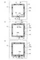
図1に示すように、液冷ジャケット1は、冷却水(図示せず)が流れるとともに一部が開口した凹部11を有するジャケット本体10に、凹部11の開口部12を封止する封止体30を摩擦攪拌接合(図3参照)によって固定して構成されている。 As shown in FIG. 1, a
液冷ジャケット1は、その下方側の中央に、熱拡散シート(図示せず)を介してCPU(図示せず)が取り付けられるようになっており、CPUが発生する熱を受熱すると共に、内部を流通する冷却水と熱交換する。これによって、液冷ジャケット1は、CPUから受け入れた熱を冷却水に伝達し、その結果として、CPUを効率的に冷却する。なお、熱拡散シートは、CPUの熱を、ジャケット本体10に効率的に伝達させるためのシートであり、例えば、銅などの高熱伝導性を有する金属から形成されている。 The
ジャケット本体10は、一方側(本実施形態では上側)が開口した浅底の箱体であって、その内側に凹部11が形成されており、底壁13と、周壁14とを有している。このようなジャケット本体10は、例えば、ダイキャスト、鋳造、鍛造などによって作製される。ジャケット本体10は、アルミニウムまたはアルミニウム合金から形成されている。これにより、液冷ジャケット1は軽量化が達成されており、取り扱い容易となっている。 The jacket
ジャケット本体10の凹部11の開口周縁部12aには、凹部11の底面側に一段下がった段差底面からなる支持面15aが形成されている。図4の(a)に示すように、ジャケット本体10の上面と支持面15aとの高低差は、封止体30の厚さ寸法T1と同じ寸法H1に設定されている。支持面15aは、封止体30を支持する面であって、支持面15a上には、封止体30の周縁部30aが載置される。また、支持面15aの幅(封止体30の周縁部30aが載置される部分の幅)寸法W1は、摩擦攪拌接合に用いられる回転ツール50のショルダー径(ショルダー部51の直径)寸法R1よりも大きく設定されている。 A
図1に示すように、凹部11の周囲の周壁14の互いに対向する一対の壁部14a,14aには、凹部11に冷却水を流通させるための貫通孔16,16がそれぞれ形成されている。貫通孔16,16は、本実施形態では、壁部14a,14aの対向方向(図1中、X軸方向)に延在しており、円形断面を有し、凹部11の深さ方向中間部に形成されている。なお、貫通孔16の形状、数および形成位置は、これに限られるものではなく、冷却水の種類や流量に応じて適宜変更可能である。 As shown in FIG. 1, through-
図1および図2に示すように、封止体30は、ジャケット本体10の段差側面15b(図1参照)と同じ形状(本実施形態では正方形)の外周形状を有する板状の蓋板部31と、蓋板部31の下面に設けられた複数のフィン32,32…とを備えて構成されている。 As shown in FIGS. 1 and 2, the sealing
フィン32は、封止体30の表面積を大きくするために設けられている。複数のフィン32,32…は、互いに平行で且つ蓋板部31に対して直交して配置されており、蓋板部31と一体に構成されている。これにより、蓋板部31とフィン32,32…との間において、熱が良好に伝達するようになっている。図1に示すように、フィン32,32…は、貫通孔16,16が形成された周壁14の壁部14a,14aと直交する方向(図1中、X軸方向)に延在するように配置されている。フィン32は、凹部11の深さ寸法と同等の高さ(深さ)寸法(図1中、Z軸方向長さ)を有しており、その先端部が凹部11の底面に当接するようになっている。これによって、封止体30がジャケット本体10に取り付けられた状態で、封止体30の蓋板部31と、隣り合うフィン32,32と、凹部11の底面とで筒状の空間が区画され、その空間が、冷却水が流れる流路33(図3の(a)参照)として機能することとなる。また、フィン32,32…は、凹部11の一辺の長さ寸法よりも短い長さ寸法(図1中、X軸方向長さ)を有しており、その両端は、周壁14の各壁部14a,14aの内壁面とそれぞれ所定の間隔を隔てるように構成されている。フィン32,32…の端部と、壁部14aとの間の空間は、フィン32,32によって形成される流路33と、貫通孔16とを繋ぐ流路ヘッダ部34(図3の(a)参照)を構成する。 The
封止体30もジャケット本体10と同様に、アルミニウムまたはアルミニウム合金から形成されている。これにより、液冷ジャケット1は軽量化が達成されており、取り扱い容易となっている。封止体30は、アルミニウムまたはアルミニウム合金から形成されたブロックを切削加工することで蓋板部31とフィン32を形成して作製されている。なお、作製方法はこれに限定されるものではなく、例えば、蓋板部31と複数のフィン32,32…からなる断面形状を有する部材を、押出成形または溝加工によって形成し、そのフィン32の両端部を取り除くことによって作製してもよい。 The sealing
次に、ジャケット本体10に、封止体30を摩擦攪拌接合によって固定する方法について、図3および図4を参照して説明する。 Next, a method for fixing the sealing
まず、図3の(a)に示すように、封止体30を、フィン32が下側になるようにして、ジャケット本体10の凹部11に挿入して、封止体30の周縁部30aを、支持面15a上に載置する。すると、ジャケット本体10の段差側面15bと、封止体30の外周面30bとが突き合わされ、突合部40が構成される。 First, as shown in FIG. 3A, the sealing
次に、摩擦攪拌接合用の回転ツール50を挿入位置53に挿入した後、突合部40の内側寄りの位置に移動させて、この突合部40に沿って移動させる。このとき、ジャケット本体10の周壁14の外周面に、ジャケット本体10を四方向から囲む治具(図示せず)を予め当てておくのが好ましい。これによれば、周壁14の厚さが薄く、回転ツール50のショルダー部51(図4の(a)参照)の外周面と、周壁14の外周面との距離(隙間)が、例えば、2.0mm以下であっても、回転ツール50の押圧力によって周壁14が外側に変形しにくくなる。なお、周壁14の厚さが厚い場合は、前記の治具は設置しなくてもよい。 Next, after the
回転ツール50は、ジャケット本体10や封止体30よりも硬質の金属材料からなり、図4の(a)に示すように、円柱状を呈するショルダー部51と、このショルダー部51の下端面に突設された攪拌ピン(プローブ)52とを備えて構成されている。回転ツール50の寸法・形状は、ジャケット本体10および封止体30の材質や厚さ等に応じて設定すればよい。本実施形態では、攪拌ピン52は、下部が縮径した円錐台状を呈しており、その突出長さ寸法は、封止体30の蓋板部31の厚さ寸法T1以上となっている。そして、摩擦攪拌接合時には、攪拌ピン52の先端が支持面15aを突き抜けるように、回転ツール50が押し込まれる。回転ツール50の回転速度は500〜15000(rpm)、送り速度は0.05〜2(m/分)で、突合部40を押さえる押込み力は1〜20(kN)程度で、ジャケット本体10および封止体30の材質や板厚および形状に応じて適宜選択される。 The
以下に、回転ツール50の動きを具体的に説明する。まず、回転ツール50を回転させながら挿入位置53に挿入する。回転ツール50の挿入位置53は、図3の(a)に示すように、突合部40から外側に外れた周壁14の上面となっている。なお、回転ツール50の挿入位置53に、予め下穴(図示せず)を形成していてもよい。このようにすれば、回転ツール50の挿入時間(押込み時間)を短縮できる。 Hereinafter, the movement of the
その後、回転ツール50を、挿入位置53から突合部40よりも内側寄りの位置へ回転させながら移動させる。内側寄りの位置は、図4の(a)に示すように、攪拌ピン52が突合部40の突合面を超えて内側に入り、且つショルダー部51の外側が突合部40の突合面を超えないで外側にある位置である。すなわち、攪拌ピン52よりも外側のショルダー部51が、突合部40の突合面を覆う位置でもある。 Thereafter, the
回転ツール50が前記した突合部40よりも内側寄りの位置まで移動したならば、図3の(a)に示すように、回転ツール50の中心(軸芯)が突合部40と一定間隔を保ちながら突合部40に沿って平行移動するように移動方向を変えて、回転ツール50を移動させる。このとき、図3の(a)および図4の(b)に示すように、回転ツール50の移動方向(図3および図4中、矢印Y1参照)の反対方向に回転ツール50が回動(図3および図4中、矢印Y2参照)するフロー側50aに突合部40が位置するように、回転ツール50を回転、移動させる。具体的には、突合部40における回転ツール50の回転方向(自転方向)が、移動方向(公転方向)と逆方向となるようにする。すなわち、本実施形態では、図3の(a)に示すように、回転ツール50を凹部11の開口部12に対して右回りに移動させているので、回転ツール50を左回転させる。なお、回転ツール50を凹部11の開口部12に対して左回りに移動させるときは、回転ツール50を右回転させることとなる。このようにすることによって、突合部40に対する回転ツール50の外周の相対速さは、回転ツール50の外周における接線速度の大きさから移動速度の大きさを減算した値となるので、回転ツール50の移動方向と同じ方向に回転ツール50が回動するシアー側50bと比較して低速となる。 If the
そして、引き続き、回転ツール50の回転および移動を継続し、図3の(b)に示すように、回転ツール50を開口部12の周りを一周させて塑性化領域41を形成する。ここで、「塑性化領域」とは、回転ツール50の摩擦熱によって加熱されて現に塑性化している状態と、回転ツール50が通り過ぎて常温に戻った状態の両方を含むこととする。回転ツール50を一周させたら、一周目の始端54aを含む始端部(始端54aから回転ツール50の移動方向に所定長さ進んだ位置(終端54bと同じ位置)までの部分)に沿って回転ツール50を所定長さ移動させる。これによって、回転ツール50の周方向移動における始端54aと終端54bとが互いにオーバーラップしており、塑性化領域41の一部が重複するように構成されている。 Subsequently, the rotation and movement of the
そして、回転ツール50の周方向移動が終了したならば、回転ツール50を塑性化領域41(突合部40)から外側に外れた周壁14の上面へと移動させ、その位置で、回転ツール50を引き抜く。このように、回転ツール50の引抜位置55が、突合部40から外側に外れた位置となっているので、攪拌ピン52(図4の(a)参照)の引抜跡が突合部40に形成されることはない。これにより、ジャケット本体10と封止体30との接合性をさらに高めることができる。なお、周壁14の上面の引抜跡は、溶接金属を埋める等の加工を行って補修するようにしてもよい。 Then, when the circumferential movement of the
以上のように、回転ツール50を凹部11の開口部12の周囲で、突合部40に沿って一周させて摩擦攪拌接合を行って塑性化領域41を形成し、ジャケット本体10に封止体30を固定することで、液冷ジャケット1が形成される。 As described above, the
本実施形態に係る液冷ジャケット1の製造方法および摩擦攪拌接合方法によれば、突合部40よりも内側寄りの位置で、摩擦攪拌接合を行ったことによって、図5に示すように、支持面15aと封止体30の下面との接合面に多くの塑性化領域41を形成することができる。これによって、ジャケット本体10と封止体30との接合面積を増加することができる。特に、回転ツール50のピン先端が支持面15aを突き抜けるように、摩擦攪拌接合を行ったことによって、支持面15aと封止体30の下面との接合面に確実に塑性化領域41が形成される。 According to the manufacturing method and the friction stir welding method of the
また、支持面15aの幅寸法W1は、回転ツール50のショルダー径寸法R1よりも大きいので、塑性化領域41が凹部11内に露出することがなく、塑性化領域41の水平方向長さの大部分を、支持面15aと封止体30の下面との接合面に位置させることができる。また、塑性化領域41が、凹部11内に露出して凹部11の内周壁が変形することがないので、流路の体積が減少することがなく、冷却性能の低下を防止できる。 Further, since the width dimension W1 of the
さらに、回転ツール50のショルダー部51が突合部40を覆うように、摩擦攪拌接合を行っているので、突合部40の全体に亘って塑性化領域41を確実に形成することができる。 Furthermore, since the friction stir welding is performed so that the
以上のように、本実施形態では、塑性化領域41は、鉛直方向に広がる突合部40部分だけでなく、水平方向に広がる支持面15aと封止体30の下面との接合面にも広く形成される。したがって、ジャケット本体10と封止体30との接合面積を増加することができ、ジャケット本体10と封止体30との接合部の密閉性能を向上させることができる。 As described above, in the present embodiment, the
また、回転ツール50のフロー側50aに突合部40が位置するように、回転ツール50の移動方向と回転方向を設定して摩擦攪拌接合を行ったことによって、突合部40に対する回転ツール50の相対速さが低速になり、メタル流動量が少なくなる。したがって、突合部におけるメタル不足による空洞欠陥の発生を防止でき、突合部40の接合強度の低下を防止できる。これによって、ジャケット本体10と封止体30との接合部の密閉性能を向上させることができる。なお、攪拌ピン52を挟んでフロー側50aの逆側に位置するシアー側50bは、突合部40から大きく離れた領域56に位置させることができるので、空洞欠陥ができたとしても問題はない In addition, the friction stir welding is performed by setting the moving direction and the rotation direction of the
さらに、本実施形態では、回転ツール50の周方向移動における始端54aと終端54bとで、塑性化領域41の一部が重複していることにより、凹部11の開口周縁部12aにおいて、塑性化領域41が途切れる部分がない。したがって、ジャケット本体10の周壁14と、封止体30とを良好に接合することができ、熱輸送流体が外部に漏れないので、接合部の密閉性能を向上させることができる。 Further, in the present embodiment, the
(第2実施形態)
次に、第2実施形態に係る液冷ジャケットの製造方法および摩擦攪拌接合方法について、図6を参照して説明する。(Second Embodiment)
Next, a method for manufacturing a liquid cooling jacket and a friction stir welding method according to the second embodiment will be described with reference to FIG.
かかる実施形態は、図6の(a)に示すように、第1実施形態の回転ツール50で塑性化領域41を形成する工程に先立って、ジャケット本体10と封止体30との突合部40の一部を回転ツール50よりも小型の仮接合用回転ツール60を用いて仮接合することを特徴とする。仮接合を行った後には、回転ツール50を用いて第1実施形態と同様の本接合を行う(図6の(b)参照)。 In this embodiment, as shown in FIG. 6A, the abutting
仮接合用回転ツール60は、回転ツール50よりも小径のショルダー部と攪拌ピン(図示せず)を備えており、形成される塑性化領域45は、後の工程で回転ツール50によって形成される塑性化領域41(図6の(b)参照)の幅よりも小さい幅を有することとなる。そして、塑性化領域45は、後の工程で塑性化領域41が形成される位置からはみ出さない位置に形成される。これによって、仮接合における塑性化領域45は、塑性化領域41で完全に覆われることとなるので、塑性化領域45に残った仮接合用回転ツール60の引抜跡および塑性化領域45の跡が残らない。 The temporary joining
本実施形態では、第1実施形態と同様に、突合部40が正方形(矩形枠状)を呈しており、仮接合用回転ツール60で突合部40を仮接合する工程において、突合部40の一方の対角44a,44b同士を先に仮接合した後に、他方の対角44c,44d同士を仮接合するようになっている。このような順序で仮接合することで、封止体30をバランスよくジャケット本体10に仮接合することができ、封止体30のジャケット本体10に対する位置決め精度が向上するとともに、封止体30の変形を防止できる。また、封止体30の仮接合を行ったことによって、回転ツール50による本接合時の封止体30のズレを防止でき、接合部の密閉性能をより一層向上させることができる。 In the present embodiment, as in the first embodiment, the abutting
(第3実施形態)
次に、第3実施形態に係る液冷ジャケットの製造方法および摩擦攪拌接合方法について、図7を参照して説明する。(Third embodiment)
Next, a method for manufacturing a liquid cooling jacket and a friction stir welding method according to the third embodiment will be described with reference to FIG.
かかる実施形態は、図7の(a)に示すように、第1実施形態の回転ツール50で塑性化領域41を形成する工程に先立って、ジャケット本体10と封止体30との突合部40の一部を回転ツール50よりも小型の仮接合用回転ツール60を用いて仮接合することを特徴とする。ここでの仮接合は、第2実施形態が、正方形の突合部40の角部を摩擦攪拌接合しているのに対して、各辺の中間部を摩擦攪拌接合することによって直線状に行われている。具体的には、突合部40が正方形(矩形枠状)を呈しており、仮接合用回転ツール60で突合部40を仮接合する工程において、突合部40の一方の対辺46,46の中間部46a,46b同士を先に仮接合した後に、他方の対辺47,47の中間部47a,47b同士を仮接合するようになっている。このとき仮接合用回転ツール60で形成される塑性化領域48は、それぞれ同じ長さの直線状になるようになっている。また、塑性化領域48は、後の工程で塑性化領域41が形成される位置からはみ出さない位置に形成される。 In this embodiment, as shown in FIG. 7A, the abutting
本実施形態では、前記のような順序で仮接合することで、封止体30をバランスよくジャケット本体10に仮接合することができ、封止体30のジャケット本体10に対する位置決め精度が向上するとともに、封止体30の変形を防止できる。また、封止体30の仮接合を行ったことによって、回転ツール50による本接合時の封止体30のズレを防止できる。さらに、本実施形態によれば、仮接合の摩擦攪拌接合が直線状であるので、仮接合用回転ツール60を直線的に移動させるだけでよく加工が容易である。 In this embodiment, by temporarily joining in the order as described above, the sealing
(第4実施形態)
次に、第4実施形態に係る液冷ジャケットの製造方法および摩擦攪拌接合方法について、図8および図9を参照して説明する。(Fourth embodiment)
Next, a method for manufacturing a liquid cooling jacket and a friction stir welding method according to the fourth embodiment will be described with reference to FIGS. 8 and 9.
かかる実施形態は、図8に示すように、回転ツール50を、一周(塑性化領域41の一部を重複させる部分まで含む)させた後に移動方向を反転させて、再度一周させることを特徴とし、さらに、二周目の回転ツール50の移動軌跡を、回転ツール50の一周目における移動で形成された塑性化領域41よりも外側へ偏移させることを特徴とする。 As shown in FIG. 8, this embodiment is characterized in that the
具体的には、まず、図8の(a)に示すように、封止体30を、ジャケット本体10の凹部(図示せず)に挿入して、封止体30の周縁部30aを、凹部の開口周縁部12aの支持面(図示せず)上に載置した後、回転ツール50を、突合部40から外側に外れた周壁14の上面の挿入位置53に挿入する。その後、回転ツール50を、突合部40の突合面よりも内側寄りの始端54aまで移動させ、さらにこの突合部40に沿って移動させて、一周目の終端54bまで塑性化領域41を形成する。ここまでの工程は第1実施形態と同様である。回転ツール50の一周目の移動は、突合部40に対して右回りとなっており(図8の(a)中、矢印Y1参照)、回転ツール50の回転方向は左回転となっている(図8の(a)中、矢印Y2参照)。 Specifically, first, as shown in FIG. 8A, the sealing
その後、図8の(b)に示すように、回転ツール50の移動方向を、一周目の終端54bで折り返して、左回りに移動する(図8中、矢印Y3参照)。このとき、回転ツール50の移動軌跡を一周目の終端54bから外側へ偏移させる。回転ツール50の偏移は、移動方向(矢印Y3)に向かうに連れて外側へ向かうように斜めに移動して、回転ツール50の軸芯が、突合部40の突合面上に位置する部分まで偏移する。その後、回転ツール50は、塑性化領域41に沿って(突合部40に沿って)平行移動する。二周目の移動に入るに際して、回転ツール50は、交換を行わず、突合部40に挿入したままの状態で、回転方向は一周目と同様に左回転(図8の(b)中、矢印Y2参照)を継続させ、押込み量も変更しない。なお、回転ツール50の回転速度や移動速度等は、ジャケット本体10と封止体30の形状や材質に応じて適宜変更してもよい。回転ツール50が一周目とは逆方向に移動して同方向に回転する二周目によって、一周目で形成された塑性化領域41をさらに攪拌する第二塑性化領域43が形成される。 Thereafter, as shown in FIG. 8B, the moving direction of the
そして、図8の(c)に示すように、回転ツール50の二周目の移動が終了したならば(本実施形態では、一周目の始端54aと同等の位置まで移動)、回転ツール50を第二塑性化領域43(突合部40)から外側に外れた周壁14の上面へと移動させ、その位置で、回転ツール50を引き抜く。なお、回転ツール50を引き抜く引抜位置55は、挿入位置53と同じである。引抜位置55は、突合部40から外側に外れた位置となっているので、引抜跡が突合部40に形成されることはなく、ジャケット本体10と封止体30との接合性をさらに高めることができる。なお、引抜跡は補修するようにしてもよい。 Then, as shown in FIG. 8C, when the movement of the second turn of the
本実施形態によれば、第1実施形態で得られる作用効果の他に、以下のような作用効果を得られる。 According to the present embodiment, the following operational effects can be obtained in addition to the operational effects obtained in the first embodiment.
本実施形態では、回転ツール50を一周させて塑性化領域41を形成した後に、この塑性化領域41に沿って回転ツール50をさらに一周させることによって、塑性化領域41よりもさらに攪拌された第二塑性化領域43が形成される。すなわち、塑性化領域41の欠陥補修を自動的に行うことができるので、接合部の密閉性能をより一層向上させることができ、信頼性の高い液冷ジャケット1を供給することができる。 In the present embodiment, the
さらに、回転ツール50の一周目と二周目における移動方向を逆方向にすることによって、塑性化領域41,43が一周目と二周目とで逆向きに攪拌されることになるので、効率的に攪拌される。したがって、空洞欠陥をより一層低減させることができ、接合部の密閉性能を向上させることができる。 Furthermore, by making the moving direction in the first and second rounds of the
また、回転ツール50の二周目における移動軌跡を、回転ツール50の一周目における移動で突合部40の内側寄りに形成された塑性化領域41よりも外側へ偏移させることによって、回転ツール50の軸芯が突合部40近傍(本実施形態では突合部40の突合面上)に位置する。これによって、回転ツール50のシアー側50bは、突合部40よりも外側寄りのジャケット本体10の厚肉部分になる。したがって、シアー側50bであっても、その周囲が厚肉であるため、メタル不足に陥ることはなく、空洞欠陥が発生しにくい。また、万一、空洞欠陥が発生したとしても、突合部40から離反した領域57(図9参照)であるので問題はない。したがって、熱輸送流体が外部に漏れにくくなり、ジャケット本体10と封止体30の接合部の密閉性能をより一層向上させることができる。 Further, the
以上、本発明の実施形態について説明したが、本発明の実施形態はこれに限定されるものではなく、本発明の趣旨を逸脱しない範囲で適宜変更が可能であり、例えば、前記実施形態では、封止体30が平面視正方形であるが、これに限定されるものではなく、長方形、多角形、円形等の他の形状であってもよい。さらに、封止体30に設けられているフィン32は、蓋板部と別体であってもよく、例えば、凹部11内に別体で収容して設けたり、ジャケット本体と一体に形成したりしもよい。 As mentioned above, although embodiment of this invention was described, embodiment of this invention is not limited to this, In the range which does not deviate from the meaning of this invention, it can change suitably, For example, in the said embodiment, Although the sealing
また、前記実施形態では、液冷ジャケットの製造方法として、ジャケット本体10と封止体30との摩擦攪拌接合方法を説明したが、摩擦攪拌接合方法の実施形態としてはこれに限られるものではなく、他の形態の金属材(ジャケット本体10に相当する第一部材と、封止体30に相当する板状の第二部材)同士の接合に適用できるのは勿論である。 Moreover, in the said embodiment, although the friction stir welding method of the jacket
1 液冷ジャケット
10 ジャケット本体
11 凹部
12 開口部
12a 開口周縁部
15a 支持面(段差底面)
15b 段差側面
30 封止体
30b 外周面
40 突合部
41 塑性化領域
50 回転ツール
50a フロー側
60 仮接合用回転ツール
H1 (ジャケット本体の上面と支持面との高低差)寸法
T1 (封止体の)厚さ寸法
R1 ショルダー径寸法
W1 (支持面の)幅寸法DESCRIPTION OF
15b Stepped
Claims (9)
Translated fromJapanese前記ジャケット本体の前記凹部の開口周縁部に、前記封止体の厚さ寸法と同じ寸法だけ下がった段差底面からなる支持面を形成し、当該支持面に前記封止体を載置して前記ジャケット本体の段差側面と前記封止体の外周面を突き合わせ、
前記ジャケット本体の前記段差側面と前記封止体の外周面との突合部よりも内側寄りの位置で、回転ツールのピン先端が前記支持面を突き抜けるとともに、前記回転ツールのフロー側に前記突合部が位置するように、前記回転ツールを回転、移動させながら前記突合部に沿って一周させて塑性化領域を形成して、前記封止体を前記ジャケット本体に固定する
ことを特徴とする液冷ジャケットの製造方法。A sealing body that seals the opening of the recess is fixed by friction stir welding to a jacket body that has a recess that is partially open while a heat transport fluid that transports heat generated by the heat generator flows to the outside. In the manufacturing method of the liquid cooling jacket constituted,
Forming a support surface consisting of a step bottom surface that is lowered by the same dimension as the thickness dimension of the sealing body on the peripheral edge of the opening of the recess of the jacket body, and placing the sealing body on the support surface The step side of the jacket body and the outer peripheral surface of the sealing body are butted,
At the position closer to the inside than the abutting portion between the step side surface of the jacket body and the outer peripheral surface of the sealing body, the pin tip of the rotating tool penetrates the support surface, and the abutting portion on the flow side of the rotating tool The rotating tool is rotated and moved so as to be positioned so as to make a round along the abutting portion to form a plasticized region, and the sealing body is fixed to the jacket body. The manufacturing method of a jacket.
ことを特徴とする請求項1に記載の液冷ジャケットの製造方法。The method for manufacturing a liquid cooling jacket according to claim 1, wherein a width dimension of the support surface is larger than a shoulder diameter dimension of the rotary tool.
ことを特徴とする請求項1または請求項2に記載の液冷ジャケットの製造方法。The method for manufacturing a liquid cooling jacket according to claim 1, wherein the rotating tool moves along the abutting portion such that a shoulder portion covers the abutting portion.
ことを特徴とする請求項1乃至請求項3のいずれか1項に記載の液冷ジャケットの製造方法。The rotating tool is moved around along the starting end of the first turn after the rotating tool makes a round along the abutting portion, and a part of the plasticizing region is overlapped. The manufacturing method of the liquid cooling jacket of any one of Claim 3.
ことを特徴とする請求項4に記載の液冷ジャケットの製造方法。After moving the rotating tool along the starting end of the first turn, the moving direction of the rotating tool is reversed, and the pin of the rotating tool is biased toward the outer peripheral side of the plasticizing region formed in the first turn. The manufacturing method of the liquid cooling jacket according to claim 4, wherein the plasticizing region is re-stirred by moving the rotating tool once again along the abutting portion.
ことを特徴とする請求項1乃至請求項5のいずれか1項に記載の液冷ジャケットの製造方法。Prior to the step of forming the plasticized region with the rotary tool, a part of the abutting portion is temporarily joined using a rotary tool for temporary joining that is smaller than the rotary tool. The manufacturing method of the liquid cooling jacket of any one of Claim 5.
前記仮接合用回転ツールで前記突合部を仮接合する工程において、前記突合部の一方の対角同士を先に仮接合した後に、他方の対角同士を仮接合する
ことを特徴とする請求項6に記載の液冷ジャケットの製造方法。The abutting portion has a rectangular frame shape,
In the step of temporarily joining the abutting portion with the temporary tool for temporary joining, after temporarily joining one diagonal of the abutting portion first, the other diagonal is temporarily joined. 6. A method for producing a liquid-cooled jacket according to 6.
前記仮接合用回転ツールで前記突合部を仮接合する工程において、前記突合部の一方の対辺の中間部同士を先に仮接合した後に、他方の対辺の中間部同士を仮接合する
ことを特徴とする請求項6に記載の液冷ジャケットの製造方法。The abutting portion has a rectangular frame shape,
In the step of temporarily joining the abutting portion with the temporary tool for temporary joining, the intermediate portions of one opposite side of the abutting portion are temporarily joined first, and then the intermediate portions of the other opposite side are temporarily joined. The manufacturing method of the liquid cooling jacket of Claim 6.
前記第一部材の前記開口部の開口周縁部に、前記第二部材の厚さ寸法と同じ寸法だけ下がった段差底面からなる支持面を形成し、当該支持面に前記第二部材を載置して前記第一部材の段差側面と前記第二部材の外周面を突き合わせ、
前記第一部材の前記段差側面と前記第二部材の外周面との突合部よりも内側寄りの位置で、回転ツールのピン先端が前記支持面を突き抜けるとともに、前記回転ツールのフロー側に前記突合部が位置するように前記回転ツールを回転、移動させながら前記突合部に沿って一周させて塑性化領域を形成して、前記第二部材を前記第一部材に固定する
ことを特徴とする摩擦攪拌接合方法。In the friction stir welding method for fixing the plate-like second member to the opening of the concave portion of the first member by friction stir welding,
A support surface consisting of a step bottom surface that is lowered by the same dimension as the thickness dimension of the second member is formed on the peripheral edge of the opening of the first member, and the second member is placed on the support surface. Abut the step side surface of the first member and the outer peripheral surface of the second member,
The pin tip of the rotating tool penetrates the support surface at a position closer to the inner side than the abutting portion between the step side surface of the first member and the outer peripheral surface of the second member, and the abutting against the flow side of the rotating tool. The second tool is fixed to the first member by forming a plasticized region by making a round along the abutting portion while rotating and moving the rotary tool so that the portion is positioned. Stir welding method.
Priority Applications (1)
| Application Number | Priority Date | Filing Date | Title |
|---|---|---|---|
| JP2008313291AJP5062155B2 (en) | 2008-12-09 | 2008-12-09 | Liquid cooling jacket manufacturing method and friction stir welding method |
Applications Claiming Priority (1)
| Application Number | Priority Date | Filing Date | Title |
|---|---|---|---|
| JP2008313291AJP5062155B2 (en) | 2008-12-09 | 2008-12-09 | Liquid cooling jacket manufacturing method and friction stir welding method |
Publications (2)
| Publication Number | Publication Date |
|---|---|
| JP2010140951A JP2010140951A (en) | 2010-06-24 |
| JP5062155B2true JP5062155B2 (en) | 2012-10-31 |
Family
ID=42350860
Family Applications (1)
| Application Number | Title | Priority Date | Filing Date |
|---|---|---|---|
| JP2008313291AActiveJP5062155B2 (en) | 2008-12-09 | 2008-12-09 | Liquid cooling jacket manufacturing method and friction stir welding method |
Country Status (1)
| Country | Link |
|---|---|
| JP (1) | JP5062155B2 (en) |
Families Citing this family (9)
| Publication number | Priority date | Publication date | Assignee | Title |
|---|---|---|---|---|
| JP5567530B2 (en) | 2011-08-19 | 2014-08-06 | 日立オートモティブシステムズ株式会社 | Friction stir welding structure and power semiconductor device |
| KR101429854B1 (en)* | 2013-05-03 | 2014-08-13 | 주식회사 보성알앤디 | Method for friction stir welding aluminum sheets using bulk process |
| CN108025391A (en)* | 2016-01-06 | 2018-05-11 | 日本轻金属株式会社 | The manufacture method of joint method and liquid-cooled jacket cylinder |
| US11141812B2 (en) | 2017-02-17 | 2021-10-12 | Mitsubishi Electric Corpration | Friction stir welding method and manufacturing method of welding structure |
| JP2020075255A (en)* | 2018-11-05 | 2020-05-21 | 日本軽金属株式会社 | Liquid cooling jacket manufacturing method and friction stir welding method |
| JP7347235B2 (en)* | 2020-01-24 | 2023-09-20 | 日本軽金属株式会社 | Liquid cooling jacket manufacturing method and friction stir welding method |
| JP7347234B2 (en)* | 2020-01-24 | 2023-09-20 | 日本軽金属株式会社 | Liquid cooling jacket manufacturing method and friction stir welding method |
| JP2025110528A (en)* | 2024-01-16 | 2025-07-29 | 日本軽金属株式会社 | Manufacturing method of the bonded body |
| JP2025110529A (en)* | 2024-01-16 | 2025-07-29 | 日本軽金属株式会社 | Manufacturing method of the bonded body |
Family Cites Families (3)
| Publication number | Priority date | Publication date | Assignee | Title |
|---|---|---|---|---|
| JP2001313357A (en)* | 2000-04-27 | 2001-11-09 | Hitachi Ltd | Heat sink plate manufacturing method and heat sink structure |
| JP4687541B2 (en)* | 2005-04-21 | 2011-05-25 | 日本軽金属株式会社 | Liquid cooling jacket |
| JP4687706B2 (en)* | 2005-04-21 | 2011-05-25 | 日本軽金属株式会社 | Liquid cooling jacket |
- 2008
- 2008-12-09JPJP2008313291Apatent/JP5062155B2/enactiveActive
Also Published As
| Publication number | Publication date |
|---|---|
| JP2010140951A (en) | 2010-06-24 |
Similar Documents
| Publication | Publication Date | Title |
|---|---|---|
| JP5110002B2 (en) | Liquid cooling jacket manufacturing method and friction stir welding method | |
| JP5262822B2 (en) | Manufacturing method of liquid cooling jacket | |
| JP5062155B2 (en) | Liquid cooling jacket manufacturing method and friction stir welding method | |
| JP5573973B2 (en) | Manufacturing method of liquid cooling jacket | |
| JP5168212B2 (en) | Manufacturing method of liquid cooling jacket | |
| JP6489219B2 (en) | Joining method, liquid cooling jacket manufacturing method, and liquid cooling jacket | |
| JP5136072B2 (en) | Manufacturing method of liquid cooling jacket | |
| JP5862272B2 (en) | Manufacturing method of liquid cooling jacket | |
| JP6443391B2 (en) | Liquid cooling jacket manufacturing method and liquid cooling jacket | |
| CN107000114B (en) | Manufacturing method of liquid-cooled sleeve and liquid-cooled sleeve | |
| JP6337632B2 (en) | Manufacturing method of liquid cooling jacket | |
| WO2017033849A1 (en) | Method for manufacturing liquid-cooled jacket, and liquid-cooled jacket | |
| JP2009297761A (en) | Method for producing heat transmit plate | |
| WO2017119232A1 (en) | Joining method and method of manufacturing liquid-cooled jacket | |
| JP5962820B2 (en) | Manufacturing method of liquid cooling jacket | |
| JP5343548B2 (en) | Manufacturing method of liquid cooling jacket | |
| JP4992865B2 (en) | Liquid cooling jacket and manufacturing method thereof | |
| US11311963B2 (en) | Method for producing liquid-cooled jacket | |
| JP5725098B2 (en) | Manufacturing method of liquid cooling jacket | |
| JP2017159351A (en) | Manufacturing method of liquid cooling jacket | |
| JP2017185500A (en) | Manufacturing method of liquid-cooled jacket |
Legal Events
| Date | Code | Title | Description |
|---|---|---|---|
| A621 | Written request for application examination | Free format text:JAPANESE INTERMEDIATE CODE: A621 Effective date:20110701 | |
| A977 | Report on retrieval | Free format text:JAPANESE INTERMEDIATE CODE: A971007 Effective date:20120622 | |
| TRDD | Decision of grant or rejection written | ||
| A01 | Written decision to grant a patent or to grant a registration (utility model) | Free format text:JAPANESE INTERMEDIATE CODE: A01 Effective date:20120710 | |
| A01 | Written decision to grant a patent or to grant a registration (utility model) | Free format text:JAPANESE INTERMEDIATE CODE: A01 | |
| A61 | First payment of annual fees (during grant procedure) | Free format text:JAPANESE INTERMEDIATE CODE: A61 Effective date:20120723 | |
| R150 | Certificate of patent or registration of utility model | Ref document number:5062155 Country of ref document:JP Free format text:JAPANESE INTERMEDIATE CODE: R150 Free format text:JAPANESE INTERMEDIATE CODE: R150 | |
| FPAY | Renewal fee payment (event date is renewal date of database) | Free format text:PAYMENT UNTIL: 20150817 Year of fee payment:3 | |
| S531 | Written request for registration of change of domicile | Free format text:JAPANESE INTERMEDIATE CODE: R313531 | |
| R350 | Written notification of registration of transfer | Free format text:JAPANESE INTERMEDIATE CODE: R350 | |
| R250 | Receipt of annual fees | Free format text:JAPANESE INTERMEDIATE CODE: R250 | |
| R250 | Receipt of annual fees | Free format text:JAPANESE INTERMEDIATE CODE: R250 |