JP5061864B2 - Television, audio signal supply apparatus and audio signal processing method - Google Patents
Television, audio signal supply apparatus and audio signal processing methodDownload PDFInfo
- Publication number
- JP5061864B2 JP5061864B2JP2007303725AJP2007303725AJP5061864B2JP 5061864 B2JP5061864 B2JP 5061864B2JP 2007303725 AJP2007303725 AJP 2007303725AJP 2007303725 AJP2007303725 AJP 2007303725AJP 5061864 B2JP5061864 B2JP 5061864B2
- Authority
- JP
- Japan
- Prior art keywords
- external speaker
- speaker device
- audio signal
- parameter
- unit
- Prior art date
- Legal status (The legal status is an assumption and is not a legal conclusion. Google has not performed a legal analysis and makes no representation as to the accuracy of the status listed.)
- Expired - Fee Related
Links
- 230000005236sound signalEffects0.000titleclaimsdescription106
- 238000003672processing methodMethods0.000titleclaimsdescription6
- 238000012937correctionMethods0.000claimsdescription50
- 238000009434installationMethods0.000claimsdescription36
- 238000000034methodMethods0.000claimsdescription36
- 238000004891communicationMethods0.000claimsdescription8
- 238000012986modificationMethods0.000description24
- 230000004048modificationEffects0.000description24
- 230000000694effectsEffects0.000description13
- 238000005259measurementMethods0.000description13
- 238000010586diagramMethods0.000description11
- 230000003321amplificationEffects0.000description10
- 238000003199nucleic acid amplification methodMethods0.000description10
- 238000013461designMethods0.000description5
- 230000035945sensitivityEffects0.000description5
- 239000004973liquid crystal related substanceSubstances0.000description3
- 230000002093peripheral effectEffects0.000description2
- 238000012545processingMethods0.000description2
- 238000005516engineering processMethods0.000description1
- 230000006870functionEffects0.000description1
- 230000010365information processingEffects0.000description1
- 230000002250progressing effectEffects0.000description1
- 238000002310reflectometryMethods0.000description1
- 238000004088simulationMethods0.000description1
Images


Landscapes
- Television Receiver Circuits (AREA)
- Details Of Audible-Bandwidth Transducers (AREA)
- Circuit For Audible Band Transducer (AREA)
Description
Translated fromJapanese本発明は、外部スピーカ装置使用時における音質調整の技術に関する。 The present invention relates to a technique for adjusting sound quality when using an external speaker device.
テレビの視聴時において、テレビの利用者は、そのテレビの内蔵スピーカや接続したヘッドホンからの放音によって音声を聴取する。このとき、テレビの内蔵スピーカから放音する場合と、ヘッドホンから放音する場合とでは、テレビの内蔵スピーカとヘッドホンの周波数特性が異なるため、内蔵スピーカとヘッドホンとを切り替えて用いる場合に、それぞれの周波数特性に応じて、オーディオ信号の周波数特性を補正して供給する技術がある(例えば、特許文献1)。
ところで、近年ではテレビは液晶ディスプレイなど薄型大画面テレビが主流となりつつあり、年々薄型化、大画面化が進んでいる。そして、テレビの筐体の大きさに対して、表示画面の領域を大きくするデザインにすることにより狭額縁化も進み、これまでその位置に配置されていた内部スピーカを小型化する必要があり、その音質が悪化することになっていた。そのため、このようなテレビの利用者は、音質に満足できない場合には、外部に高音質のスピーカ装置を設けて、そのスピーカ装置を用いてテレビの視聴を行うことが多くなってきた。また、複数の種類のスピーカ装置を設け、視聴内容に応じて使い分けるといった使用もされている。 By the way, in recent years, thin large-screen televisions such as liquid crystal displays are becoming mainstream, and the thinning and large screen are progressing year by year. And with the design of the display screen area larger than the size of the housing of the TV, the frame is also narrowed, and it is necessary to downsize the internal speaker that has been placed at that position so far, The sound quality was supposed to deteriorate. For this reason, when the user of such a television is not satisfied with the sound quality, a high sound quality speaker device is provided outside, and the television device is often viewed using the speaker device. In addition, a plurality of types of speaker devices are provided and used in accordance with viewing contents.
ここで、特許文献1に開示された技術においては、テレビに接続されるヘッドホンの種類を変えたとしてもオーディオ信号の周波数特性の補正内容は変わらないが、ヘッドホンの周波数特性は大きく変わるものではないから所望の放音が得られる。一方、ヘッドホンではなくスピーカ装置の場合には、その種類によって周波数特性が大きく異なる場合が多い。ところが、特許文献1に開示された技術を用いたテレビにおいては、接続されるスピーカ装置の種類が変わっても、オーディオ信号の周波数特性の補正内容が変わることがないから所望の放音が得られない。 Here, in the technique disclosed in Patent Document 1, even if the type of headphones connected to the television is changed, the correction content of the frequency characteristics of the audio signal does not change, but the frequency characteristics of the headphones do not change significantly. Can produce the desired sound emission. On the other hand, in the case of a speaker device instead of a headphone, the frequency characteristics often vary greatly depending on the type. However, in a television using the technique disclosed in Patent Document 1, even if the type of the speaker device to be connected changes, the correction content of the frequency characteristic of the audio signal does not change, so that a desired sound emission can be obtained. Absent.
このように、外部接続するスピーカ装置には、単なる放音だけでは種類によって様々な周波数特性を持つことが多いから、所望の周波数特性を得るためにオーディオ信号を補正する音質調整回路を設ける必要があり、高コストの要因となっている。また、スピーカ装置がテレビ台などに組み込まれている場合、スピーカの配置を工夫することよって音質調整回路の負荷を減らすこともできる一方、スピーカの配置の制限により、外形のデザインの自由度が制限されることになっていた。 As described above, since an externally connected speaker device often has various frequency characteristics depending on the type of sound output, it is necessary to provide a sound quality adjustment circuit for correcting an audio signal in order to obtain a desired frequency characteristic. There is a high cost factor. In addition, when the speaker device is incorporated in a TV stand or the like, the load on the sound quality adjustment circuit can be reduced by devising the arrangement of the speakers, while the restriction on the arrangement of the speakers limits the degree of freedom in designing the outer shape. Was supposed to be done.
本発明は、上述の事情に鑑みてなされたものであり、外部接続する外部スピーカ装置を低コストかつ自由なデザインで提供可能とするテレビ、AVシステム、オーディオ信号供給装置およびオーディオ信号処理方法を提供することを目的とする。 The present invention has been made in view of the above circumstances, and provides a television, an AV system, an audio signal supply device, and an audio signal processing method that can provide an external speaker device to be externally connected at a low cost and a free design. The purpose is to do.
上述の課題を解決するため、本発明は、入力される映像信号に基づいて、表示面に表示を行う表示手段と、前記表示面の周辺部に配置され、供給されるオーディオ信号を放音する内部スピーカと、外部スピーカ装置が接続され、供給されるオーディオ信号を当該接続される外部スピーカ装置に出力する接続端子と、内部スピーカ用パラメータを記憶する第1の記憶手段と、前記外部スピーカ装置の種類に対応した外部スピーカ装置用パラメータを複数記憶する第2の記憶手段と、オーディオ信号が入力される入力手段と、前記入力手段に入力されるオーディオ信号に対して、設定されるパラメータに基づいて音響特性の調整を行う音響特性調整手段と、前記内部スピーカまたは前記接続端子のいずれかを選択する出力選択手段と、前記第2の記憶手段に記憶された複数の外部スピーカ装置用パラメータから、一の外部スピーカ装置用パラメータを選択するパラメータ選択手段と、前記出力選択手段によって前記内部スピーカが選択された場合には、前記第1の記憶手段に記憶された前記内部スピーカ用パラメータを前記音響特性調整手段に設定し、前記接続端子が選択された場合には、前記パラメータ選択手段によって選択された前記外部スピーカ装置用パラメータを前記音響特性調整手段に設定する設定手段と、前記外部スピーカ装置の設置状況に対応した補正データを複数記憶する第3の記憶手段と、前記第3の記憶手段に記憶された補正データに対応する設置状況の中から、一の設置状況を選択する操作手段と、前記操作手段によって選択された設置状況に対応する補正データを選択する補正データ選択手段と、前記音響特性調整手段に設定されるパラメータを、前記補正データ選択手段によって選択された補正データによって補正するパラメータ補正手段と、前記出力選択手段によって選択された前記内部スピーカまたは前記接続端子に対して、前記音響特性調整手段により音響特性を調整済みのオーディオ信号を供給する供給手段とを具備することを特徴とするテレビを提供する。In order to solve the above-described problems, the present invention provides display means for performing display on a display surface based on an input video signal, and emits a supplied audio signal that is disposed in a peripheral portion of the display surface. An internal speaker and an external speaker device are connected, a connection terminal for outputting a supplied audio signal to the connected external speaker device, first storage means for storing internal speaker parameters, and the external speaker device A second storage means for storing a plurality of parameters for the external speaker device corresponding to the type; an input means for inputting an audio signal; and an audio signal input to the input means based on parameters set. Acoustic characteristic adjusting means for adjusting acoustic characteristics; output selecting means for selecting either the internal speaker or the connection terminal; and the second When the internal speaker is selected by the parameter selection means for selecting one external speaker device parameter from the plurality of external speaker device parameters stored in the storage means and the output selection means, the first speaker The internal speaker parameter stored in the storage means is set in the acoustic characteristic adjusting means, and when the connection terminal is selected, the external speaker device parameter selected by the parameter selecting means is used as the acoustic characteristic. Setting means for setting the adjusting means,third storage means for storing a plurality of correction data corresponding to the installation status of the external speaker device, and installation status corresponding to the correction data stored in the third storage means The operation means for selecting one installation status from among the above, and the correction data corresponding to the installation status selected by the operation means. Correction data selection means for selecting, the acoustic characteristic parameters that are set in the adjusting means, and the parameter correcting means for correcting by the correction data selected by said correction data selecting means, said internal selected by said output selection means Provided is a television, comprising: a supply unit that supplies an audio signal whose acoustic characteristics have been adjusted by the acoustic characteristic adjusting unit to a speaker or the connection terminal.
また、別の好ましい態様において、前記接続端子に接続される外部スピーカ装置の種類を識別する識別手段をさらに具備し、前記パラメータ選択手段は、前記識別手段によって識別された外部スピーカ装置の種類に対応するパラメータを選択してもよい。 In another preferable aspect, the information processing apparatus further includes an identification unit that identifies a type of the external speaker device connected to the connection terminal, and the parameter selection unit corresponds to the type of the external speaker device identified by the identification unit. The parameter to be selected may be selected.
また、別の好ましい態様において、前記識別手段は、前記接続端子に接続される外部スピーカ装置の種類を、当該外部スピーカ装置に設けられた識別抵抗体の抵抗値を測定することによって識別してもよい。 In another preferable aspect, the identification unit may identify the type of the external speaker device connected to the connection terminal by measuring a resistance value of an identification resistor provided in the external speaker device. Good.
また、別の好ましい態様において、前記識別手段は、前記接続端子に接続される外部スピーカ装置の種類を、当該外部スピーカ装置に描画された図形を光学的に読み取ることによって識別してもよい。 In another preferable aspect, the identification unit may identify the type of the external speaker device connected to the connection terminal by optically reading a figure drawn on the external speaker device.
また、別の好ましい態様において、前記識別手段は、前記接続端子に接続される外部スピーカ装置の種類を、当該外部スピーカ装置の記憶手段に記憶された識別情報を取得することによって識別してもよい。 In another preferable aspect, the identification unit may identify the type of the external speaker device connected to the connection terminal by acquiring identification information stored in the storage unit of the external speaker device. .
また、別の好ましい態様において、前記識別手段は、無線通信手段を有し、前記識別手段は、識別した外部スピーカ装置の種類を示す情報を、前記無線通信手段によって前記パラメータ選択手段に対して送信し、前記パラメータ選択手段は、前記無線通信手段によって送信された情報を受信し、当該情報が示す外部スピーカ装置の種類に対応するパラメータを選択してもよい。 In another preferable aspect, the identification unit includes a wireless communication unit, and the identification unit transmits information indicating the type of the identified external speaker device to the parameter selection unit by the wireless communication unit. The parameter selection unit may receive information transmitted by the wireless communication unit and select a parameter corresponding to the type of the external speaker device indicated by the information.
また、本発明は、入力される映像信号に基づいて、表示面に表示を行う表示手段と、前記表示面の周辺部に配置され、供給されるオーディオ信号を放音する内部スピーカと、外部スピーカ装置が接続され、供給されるオーディオ信号を当該接続される外部スピーカ装置に出力する接続端子とを有するテレビに用いられるオーディオ信号供給装置であって、内部スピーカ用パラメータを記憶する第1の記憶手段と、前記外部スピーカ装置の種類に対応した外部スピーカ装置用パラメータを複数記憶する第2の記憶手段と、オーディオ信号が入力される入力手段と、前記入力手段に入力されるオーディオ信号に対して、設定されるパラメータに基づいて音響特性の調整を行う音響特性調整手段と、前記内部スピーカまたは前記接続端子のいずれかを選択する出力選択手段と、前記第2の記憶手段に記憶された複数の外部スピーカ装置用パラメータから、一の外部スピーカ装置用パラメータを選択するパラメータ選択手段と、前記出力選択手段によって前記内部スピーカが選択された場合には、前記第1の記憶手段に記憶された前記内部スピーカ用パラメータを前記音響特性調整手段に設定し、前記接続端子が選択された場合には、前記パラメータ選択手段によって選択された前記外部スピーカ装置用パラメータを前記音響特性調整手段に設定する設定手段と、前記外部スピーカ装置の設置状況に対応した補正データを複数記憶する第3の記憶手段と、前記第3の記憶手段に記憶された補正データに対応する設置状況の中から、一の設置状況を選択する操作手段と、前記操作手段によって選択された設置状況に対応する補正データを選択する補正データ選択手段と、前記音響特性調整手段に設定されるパラメータを、前記補正データ選択手段によって選択された補正データによって補正するパラメータ補正手段と、前記出力選択手段によって選択された前記内部スピーカまたは前記接続端子に対して、前記音響特性調整手段により音響特性を調整済みのオーディオ信号を供給する供給手段とを具備することを特徴とするオーディオ信号供給装置を提供する。The present invention also provides display means for displaying on a display surface based on an input video signal, an internal speaker arranged around the display surface and emitting a supplied audio signal, and an external speaker An audio signal supply device for use in a television having a connection terminal for outputting a supplied audio signal to the connected external speaker device, and a first storage means for storing internal speaker parameters A second storage means for storing a plurality of external speaker device parameters corresponding to the type of the external speaker device, an input means for inputting an audio signal, and an audio signal input to the input means, Acoustic characteristic adjustment means for adjusting acoustic characteristics based on set parameters, either the internal speaker or the connection terminal An output selection means for selecting; a parameter selection means for selecting one external speaker device parameter from a plurality of external speaker device parameters stored in the second storage means; and the output speaker selects the internal speaker. When selected, the internal speaker parameters stored in the first storage means are set in the acoustic characteristic adjusting means, and when the connection terminal is selected, the parameters are selected by the parameter selecting means. In addition, the setting means for setting the external speaker device parameters in the acoustic characteristic adjusting means,the third storage means for storing a plurality of correction data corresponding to the installation status of the external speaker apparatus, and the third storage means The operation means for selecting one installation situation from the installation situations corresponding to the stored correction data, and the operation means And correction data selecting means for selecting the correction data corresponding to the-option has been installed situation, the parameters set in the acoustic characteristic adjustment means, and the parameter correcting means for correcting by the correction data selected by said correction data selecting means, An audio signal supply comprising: a supply unit configured to supply an audio signal whose acoustic characteristics have been adjusted by the acoustic characteristic adjustment unit to the internal speaker or the connection terminal selected by the output selection unit. Providing equipment.
また、本発明は、入力される映像信号に基づいて、表示面に表示を行う表示手段と、前記表示面の周辺部に配置され、供給されるオーディオ信号を放音する内部スピーカと、外部スピーカ装置が接続され、供給されるオーディオ信号を当該接続される外部スピーカ装置に出力する接続端子と、内部スピーカ用パラメータを記憶する第1の記憶手段と、前記外部スピーカ装置の種類に対応した外部スピーカ装置用パラメータを複数記憶する第2の記憶手段と、前記外部スピーカ装置の設置状況に対応した補正データを複数記憶する第3の記憶手段とを具備するテレビに用いられるオーディオ信号処理方法であって、オーディオ信号が入力される入力過程と、前記入力過程において入力されるオーディオ信号に対して、設定されるパラメータに基づいて音響特性の調整を行う音響特性調整過程と、前記内部スピーカまたは前記接続端子のいずれかを選択する出力選択過程と、前記第2の記憶手段に記憶された複数の外部スピーカ装置用パラメータから、一の外部スピーカ装置用パラメータを選択するパラメータ選択過程と、前記出力選択過程によって前記内部スピーカが選択された場合には、前記第1の記憶手段に記憶された前記内部スピーカ用パラメータを前記音響特性調整過程に設定し、前記接続端子が選択された場合には、前記パラメータ選択過程によって選択された前記外部スピーカ装置用パラメータを前記音響特性調整過程に設定する設定過程と、前記第3の記憶手段に記憶された補正データに対応する設置状況の中から、一の設置状況を選択する操作過程と、前記操作手段によって選択された設置状況に対応する補正データを選択する補正データ選択過程と、前記音響特性調整手段に設定されるパラメータを、前記補正データ選択手段によって選択された補正データによって補正するパラメータ補正過程と、前記出力選択過程によって選択された前記内部スピーカまたは前記接続端子に対して、前記音響特性調整過程により音響特性を調整済みのオーディオ信号を供給する供給過程とを備えることを特徴とするオーディオ信号処理方法を提供する。The present invention also provides display means for displaying on a display surface based on an input video signal, an internal speaker arranged around the display surface and emitting a supplied audio signal, and an external speaker A connection terminal for outputting a supplied audio signal to the connected external speaker device, first storage means for storing parameters for the internal speaker, and an external speaker corresponding to the type of the external speaker device An audio signal processing method used in a television, comprising: second storage means for storing a plurality of device parameters; andthird storage means for storing a plurality of correction data corresponding to the installation status of the external speaker device. An input process in which an audio signal is input, and an audio signal input in the input process, based on a set parameter. And an acoustic characteristic adjustment process for adjusting the acoustic characteristics, an output selection process for selecting either the internal speaker or the connection terminal, and a plurality of parameters for the external speaker device stored in the second storage means, When the internal speaker is selected by the parameter selection process of selecting one external speaker device parameter and the output selection process, the internal speaker parameter stored in the first storage means is the acoustic characteristic. A setting process for setting the external speaker device parameter selected in the parameter selection process in the acoustic characteristic adjustment process when the connection terminal is selected in the adjustment process; andthe third storage means An operation process of selecting one installation situation from the installation situations corresponding to the correction data stored in Thus, a correction data selection process for selecting correction data corresponding to the selected installation situation, and a parameter correction process for correcting the parameters set in the acoustic characteristic adjustment means with the correction data selected by the correction data selection means, , audio signal processing, characterized in that it comprises with respect to the output selection process the internal speaker or the connection terminal selected by, and said acoustic characteristic adjustment process supplying step of supplying the adjusted audio signal the acoustic characteristics by Provide a method.
本発明によれば、外部接続する外部スピーカ装置を低コストかつ自由なデザインで提供可能とするテレビ、AVシステム、オーディオ信号供給装置およびオーディオ信号処理方法を提供することができる。 According to the present invention, it is possible to provide a television, an AV system, an audio signal supply device, and an audio signal processing method that can provide an external speaker device to be externally connected at a low cost and a free design.
以下、本発明の一実施形態について説明する。 Hereinafter, an embodiment of the present invention will be described.
<実施形態>
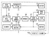
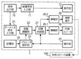
本発明の実施形態に係るテレビ1は、液晶ディスプレイ、プラズマディスプレイ、有機ELディスプレイなどの薄型テレビであり、内部にスピーカを有するとともに、外部にスピーカ装置を接続するための端子を有している。テレビ1の構成について、図1、図2を用いて説明する。図1は、テレビ1の構成を示すブロック図であり、図2は、テレビ1の外観を示す説明図である。なお、テレビ1は、図示しないCPU(Central Processing Unit)を有し、このCPUは、テレビ1の各部を制御している。<Embodiment>
A television 1 according to an embodiment of the present invention is a thin television such as a liquid crystal display, a plasma display, and an organic EL display, and has a speaker inside and a terminal for connecting a speaker device to the outside. The configuration of the television 1 will be described with reference to FIGS. FIG. 1 is a block diagram illustrating a configuration of the television 1, and FIG. 2 is an explanatory diagram illustrating an appearance of the television 1. The television 1 has a CPU (Central Processing Unit) (not shown), and this CPU controls each part of the television 1.
信号出力部10は、テレビチューナ、DVD(Digital Versatile Disc)再生装置などからのデータを受信することにより、また、図示しないCPUの制御に応じて、映像信号とオーディオ信号を生成し、映像信号については映像信号入力部11を介して表示部12へ、オーディオ信号についてはオーディオ信号入力部21を介して音質調整部22へ出力する。 The
表示部12は、液晶ディスプレイ、プラズマディスプレイ、有機ELディスプレイなどの表示デバイスであって、表示面12−Dに、映像信号入力部11から入力された映像信号に基づいた表示を行う。表示面12−Dは、図2に示すように、筐体50の正面に配置されている。 The
音質調整部22は、オーディオ信号入力部21から入力されたオーディオ信号について、後述するパラメータ設定部23から設定されるパラメータに基づいて音響特性の調整を行う。本実施形態においては、音響特性は周波数特性であって、音質調整部22は、設定されたパラメータに基づいてオーディオ信号の周波数特性を調整するイコライザである。そして、周波数特性が調整されたオーディオ信号を増幅部26に出力する。 The sound
操作部24は、リモコンなどを有し、テレビ1の利用者が操作部24を操作すると、その操作内容を表す情報が図示しないCPUへ出力される。操作部24は、テレビ1の内部スピーカ28から放音させるか、接続端子29に接続される外部スピーカ装置100から放音させるかを選択する操作により、パラメータ設定部23および切替供給部27に対して、内部スピーカまたは接続端子を示す切替情報を出力する。ここで、リモコンは、操作キーと、操作キーの操作に応じた信号を電波や赤外線などにより送信する無線通信手段とを有し、操作部24は、リモコンから送信される信号を受信する受信手段を有する。そして、操作部24は受信手段が受信した信号に基づいて操作内容を判別する。 The
また、操作部24の操作によって、接続端子29に接続される外部スピーカ装置100の種類を入力すると、この種類を示す種類情報をパラメータ設定部23に出力する。なお、これらの選択、入力時には、表示部12の表示面12−Dに、この選択内容、入力内容を示す表示を行なってもよい。また、後述する記憶部25に外部スピーカ用パラメータが記憶されている外部スピーカ装置100の種類を、表示面12−Dに表示させて、表示された中から選択することにより、接続される外部スピーカ装置100の種類を入力するようにしてもよい。 When the type of the
ここで、外部スピーカ装置100とは、様々なスピーカ装置が用いられるが、例えば、外部スピーカ装置100は、図3に示すように、スピーカ101が2つ設置されたテレビ台である。この外部スピーカ装置100は、オーディオ信号の周波数特性などの音響特性を調整する回路、アンプなどは有さず、各スピーカ101に供給されたオーディオ信号をそのまま放音する。このように、外部スピーカ装置100は、音響特性を調整する回路などを有さないため、低コストの装置とすることができる。 Here, various speaker devices are used as the
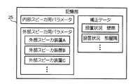
記憶部25は、音質調整部22に設定されるパラメータが記憶されている。図4に示すように、記憶部25には、内部スピーカ28の周波数特性に基づいて生成された内部スピーカ用パラメータと、外部スピーカ装置100が有する固有の周波数特性に基づいて生成された外部スピーカ用パラメータとが記憶されている。特に、外部スピーカ用パラメータについては、「外部スピーカ装置A」、「外部スピーカ装置B」、「外部スピーカ装置C」、・・・として、外部スピーカ装置の種類に対応した外部スピーカ用パラメータが記憶されている。すなわち、外部スピーカ用パラメータのうち、「外部スピーカ装置A」に対応したパラメータは、「外部スピーカ装置A」が有する固有の周波数特性に基づいて生成された「外部スピーカ装置A」専用のパラメータとなっている。このパラメータは、各周波数帯域において、どの程度のゲインを行うかを示すものであり、音質調整部22は、設定されるパラメータが示す内容に応じて、入力されたオーディオ信号の周波数特性の調整を行う。ここで、外部スピーカ装置の種類とは、本実施形態においては、外部スピーカ装置100の機種を示すものとする。なお、外部スピーカ装置の種類は、外部スピーカ装置100の同一機種内の個々を示すものとしてもよく、この場合には、各外部スピーカ用パラメータは、個々の周波数特性の個体差に応じたものとすることができる。また、外部スピーカ装置の種類は、外部スピーカ装置100の複数機種をまとめたものを示してもよく、同じ周波数特性をもつ機種は同一の種類とすることで、重複するパラメータを記憶しないようにすることもできる。このように、外部スピーカ装置の種類の分類は、固有の周波数特性が同一である、または同一とみなせる外部スピーカ装置100を1種類として行われるようにすればよい。 The
パラメータ設定部23は、操作部24から出力される切替情報および種類情報に基づいて、記憶部25からパラメータを読み出し、音質調整部22に設定する。パラメータ設定部23は、切替情報が入力されると、その切替情報が内部スピーカを示す場合には、内部スピーカから放音させるものとして、記憶部25から内部スピーカ用パラメータを読み出して音質調整部22に設定する。一方、切替情報が接続端子を示す場合には、記憶部25から外部スピーカ用パラメータを読み出すが、このときには、入力された種類情報が示す外部スピーカ装置の種類に対応した外部スピーカ用パラメータを読み出して、音質調整部22に設定する。例えば、種類情報が「外部スピーカ装置B」を示す場合には、外部スピーカ用パラメータのうち、「外部スピーカ装置B」に対応したパラメータを読み出して音質調整部22に設定する。 The
増幅部26は、入力されたオーディオ信号を所定の増幅率で増幅するアンプであって、増幅したオーディオ信号を切替供給部27に出力する。所定の増幅率は、操作部24、図示しないボリュームなどを操作することによって設定される音量値に応じて変化する。 The amplifying
切替供給部27は、入力されるオーディオ信号を、操作部24からの切替情報の内容に応じて、内部スピーカ28または接続端子29に出力する。すなわち、切替情報が内部スピーカを示している場合には、増幅部26から入力されたオーディオ信号を内部スピーカ28へ供給する。一方、切替情報が接続端子を示している場合には、増幅部26から入力されたオーディオ信号を接続端子29へ供給する。 The switching
内部スピーカ28は、供給されるオーディオ信号を放音する。このオーディオ信号は、音質調整部22において内部スピーカ用パラメータに基づいて周波数特性を調整済みのオーディオ信号となる。 The
内部スピーカ28は、図2に示すように、表示面12−Dの周辺部に配置され、本実施形態においては、筐体50の内部であって、表示面12−Dの左右に配置されている。また筐体50内の内部スピーカ28からの放音が筐体50の外部に放出される開口部が、筐体50の正面方向に設けられている。内部スピーカ28が配置される領域は、表示面12−Dの領域に比べて非常に小さく、筐体50の正面方向における表示面12−D以外の領域(以下、額縁という)の一部に設けられている。そして、この筐体50は、支持台51、回転軸体52によって支持されている。 As shown in FIG. 2, the
このように、テレビ1の全体の大きさに比べて表示面12−Dの領域の割合を大きくするデザインが用いられ、額縁が非常に狭くなっているため、この額縁の部分に配置しなくてはならないスピーカは、配置できる空間の容積が狭いために高品質な音質で放音可能なスピーカを用いることができない。なお、本実施形態は一例であって、内部スピーカ28は、表示面12−Dを有する筐体50内に配置されている場合に限られず、表示面12−Dを有する筐体50と接続された別の筐体に配置されていてもよい。また、開口部の方向、スピーカの配置方向などは、設計に応じて様々な態様とすることができる。 In this way, a design is used in which the proportion of the area of the display surface 12-D is larger than the overall size of the television 1, and the frame is very narrow. As a speaker that should not be used, a speaker that can emit sound with high quality sound quality cannot be used because the volume of the space in which it can be placed is small. The present embodiment is an example, and the
接続端子29は、様々な種類の外部スピーカ装置100が接続され、供給されるオーディオ信号を接続される外部スピーカ装置100に出力する。このオーディオ信号は、音質調整部22において外部スピーカ用パラメータに基づいて周波数特性を調整済みのオーディオ信号となる。以上が、テレビ1の構成の説明である。 The
次に、テレビ1の動作について説明する。テレビ1の接続端子29には、外部スピーカ装置100が接続されている。この外部スピーカ装置の種類は、「外部スピーカ装置C」とする。 Next, the operation of the television 1 will be described. An
テレビ1の利用者は、内部スピーカ28から放音させたいときに、操作部24を操作して内部スピーカを選択すると、操作部24から内部スピーカを示す切替情報がパラメータ設定部23および切替供給部27に出力される。そして、音質調整部22には内部スピーカ用パラメータが設定される。これにより、内部スピーカ用パラメータに基づいて周波数特性を調整済みのオーディオ信号が内部スピーカ28から放音される。 When the user of the television 1 wants to emit sound from the
続いて、外部スピーカ装置100から放音させたいときには、利用者は操作部24を操作して接続端子を選択するとともに、接続端子29に接続される外部スピーカ装置100の種類「外部スピーカ装置C」を入力する。これにより、操作部24から接続端子を示す切替情報がパラメータ設定部23および切替供給部27に出力される。パラメータ設定部23には、さらに「外部スピーカ装置C」を示す種類情報が出力される。そして、音質調整部22には、「外部スピーカ装置C」に対応する外部スピーカ用パラメータが設定され、この外部スピーカ用パラメータに基づいて周波数特性を調整済みのオーディオ信号が接続端子29に供給される。 Subsequently, when the user wants to emit sound from the
外部スピーカ装置100は、接続端子29からオーディオ信号が入力され、このオーディオ信号を放音する。ここで、内部スピーカ28にはオーディオ信号が供給されないから、内部スピーカ28からは放音されない。 The
ここでは、接続端子29に接続されている外部スピーカ装置100の種類は「外部スピーカ装置C」としたが、接続端子29に接続される外部スピーカ装置100の種類を変更して、例えば「外部スピーカ装置A」とする場合には、操作部24の操作により「外部スピーカ装置A」を入力し、音質調整部22に設定されるパラメータを「外部スピーカ装置A」に対応する外部スピーカ用パラメータに変更すればよい。 Here, the type of the
このように、本発明の実施形態に係るテレビ1は、音質調整部22に設定されるオーディオ信号の周波数特性調整時のパラメータについて、内部スピーカ用パラメータとは別に、外部スピーカ装置100の種類に対応した外部スピーカ用パラメータを記憶部25に複数記憶している。接続端子29に接続された外部スピーカ装置100の種類に対応した外部スピーカ用パラメータを選択して、音質調整部22に設定することにより、外部スピーカ装置100の種類が変わっても、同様な周波数特性の放音を行うことができる。 As described above, the television 1 according to the embodiment of the present invention is compatible with the type of the
そして、外部スピーカ装置100において、オーディオ信号の周波数特性の調整を行うかわりに、テレビ1において周波数特性の調整を行うから、外部スピーカ装置100には、音響特性の調整回路を用いる必要が無く、低コストの装置とすることができる。また、スピーカの配置により周波数特性の調整を行わなくてもよいから、外部スピーカ装置100のデザインの自由度を向上させることができる。 Then, instead of adjusting the frequency characteristic of the audio signal in the
さらに、外部スピーカ装置100自体の周波数特性を生かした放音をすることができる。すなわち、一般的な外部スピーカ装置100においては、周波数特性の調整が行われ、感度が低い周波数帯域にあわせるために、感度が高い周波数帯域の出力を抑える調整が行われる。一方、本発明の実施形態に係るテレビ1に接続される外部スピーカ装置100は、このような調整を行う必要がなく、感度の高い周波数帯域は、感度が高いまま放音することができるから、効率よく放音することができる。 Furthermore, sound can be emitted utilizing the frequency characteristics of the
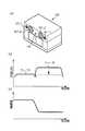
上記の効率よく放音することができるという効果について、具体例を図5、図6を用いて説明する。外部スピーカ装置100は、図5(a)に示すように、高周波数帯域を放音するツィータ101−1、低周波数帯域を放音するウーファ101−2を有している。ツィータ101−1とウーファ101−2とは、各周波数帯域において同じ出力レベルのオーディオ信号が入力されても、ツィータ101−1とウーファ101−2の能率の違いから図5(b)の実線で示すように、出力音圧が周波数帯域によって異なり、入力されるオーディオ信号に対する感度が異なる場合がある。従来は、この感度が周波数帯域によって異ならないように、能率の高いスピーカ(図5の場合にはツィータ101−1)の能率を下げ、破線で示すような特性になるようにしていた。これは、例えば、図6(a)に示すように、抵抗R1、R2を用いて実現していた。 A specific example of the effect that the sound can be emitted efficiently will be described with reference to FIGS. As shown in FIG. 5A, the
一方、本発明の実施形態に係るテレビ1は、音質調整部22において、接続端子29に接続される外部スピーカ装置100の種類に応じて、オーディオ信号に対する調整を行うことができる。外部スピーカ装置100が図5(b)の実線で示すような周波数特性を持っている場合には、この外部スピーカ装置100の種類に対応する外部スピーカ用パラメータは、図5(c)に示すように、低周波数帯域におけるオーディオ信号の出力レベルを相対的に増加させるようなパラメータとなっている。そして、音質調整部22は、このパラメータに応じてオーディオ信号の周波数特性の調整を行うから、外部スピーカ装置100は、図6(b)に示すように抵抗R1、R2を用いずに、能率の高いスピーカをそのまま用いても、出力音圧が周波数依存性を持たないようにすることができる。これにより、外部スピーカ装置100の駆動電力を少なくすることができ、効率のよい放音が可能となる。 On the other hand, the television 1 according to the embodiment of the present invention can adjust the audio signal in the sound
以上、本発明の実施形態について説明したが、本発明は以下のように、さまざまな態様で実施可能である。 As mentioned above, although embodiment of this invention was described, this invention can be implemented in various aspects as follows.
<変形例1>
上述した実施形態においては、外部スピーカ装置100が接続される端子は、増幅部26からのオーディオ信号が供給される接続端子29であったが、図7に示すように、増幅部26における増幅が行われる前のオーディオ信号、すなわち音質調整部22において周波数特性が調整されたオーディオ信号が供給される第2接続端子30を設けてもよい。この場合は、音質調整部22と増幅部26との間に切替供給部31を設け、操作部24からの切替情報が内部スピーカを示す場合には増幅部26に対して、接続端子を示す場合には増幅部26および第2接続端子30に対して、音質調整部22から入力される周波数特性が調整されたオーディオ信号を出力するようにすればよい。<Modification 1>
In the embodiment described above, the terminal to which the
なお、切替供給部31は、切替情報が接続端子を示すときには種類情報も取得して、種類情報が示す外部スピーカ装置100がアンプを有している場合には、第2接続端子にオーディオ信号を出力し、アンプを有していない場合には、増幅部26にオーディオ信号を出力するようにしてもよい。ここで、種類情報が示す外部スピーカ装置100がアンプを有しているか否かについては、操作部24の操作によって入力して種類情報にアンプ有無の情報が含まれるようにし、この情報に基づいて判断してもよいし、記憶部25に外部スピーカ装置100の種類とアンプの有無との対応テーブルを記憶させ、この種類情報と対応テーブルとを参照して判断してもよい。 The switching
このようにすると、外部スピーカ装置100が入力されたオーディオ信号を増幅するアンプを有している場合であっても、第2接続端子30に接続することができるから、アンプの有無にかかわらず外部スピーカ装置100をテレビ1に接続することができる。なお、外部スピーカ装置100がアンプを有し、さらに周波数特性を調整する回路を有している場合には、音質調整部22におけるオーディオ信号の調整が行われない、すなわちフラットな特性のまま出力するパラメータが設定されるようにしてもよい。周波数特性を調整する回路を有しているか否かの判断は、アンプの有無の判断と同様にして行えばよい。 In this way, even if the
<変形例2>
上述した実施形態においては、音質調整部22は、オーディオ信号の周波数特性を調整するイコライザとしていたが、外部スピーカ装置100におけるスピーカ101の配置の違い、特性の違いなどにより変化する音響特性を調整するものであれば、どのような特性を調整するようにしてもよい。例えば、サラウンド効果は、スピーカ101間の距離などに応じて変化する場合がある。このようなサラウンド効果を外部スピーカ装置100の種類が変わっても一定にするためのパラメータを外部スピーカ装置100の種類に対応して記憶部25に記憶させる。そして、音質調整部22は、設定されるパラメータに応じてサラウンド効果を与える調整を入力されるオーディオ信号に施すようにすればよい。<Modification 2>
In the above-described embodiment, the sound
<変形例3>
上述した実施形態においては、音質調整部22は、オーディオ信号の周波数特性を設定されたパラメータに基づいて調整し、外部スピーカ装置100の設置状況にかかわらず、同じ調整を行っていたが、設置状況に応じて調整内容を変更するようにしてもよい。この場合には、図8に示すように、記憶部25に壁際、部屋隅などの設置状況に対応する補正データを記憶させる。そして、操作部24の操作によって設置状況を入力すると、操作部24から設置状況情報がパラメータ設定部23に出力され、パラメータ設定部23は、設置状況情報が示す設置状況に対応する補正データを記憶部25から読み出す。そして、音質調整部22に設定する外部スピーカ用パラメータ、または設定されたパラメータを、読み出した補正データに基づいて補正するようにすればよい。<Modification 3>
In the embodiment described above, the sound
外部スピーカ装置100が壁際に設置されると、低音の壁面反射の効果が大きくなり、低音が強化された放音となる。これは部屋隅などに設置され、近くの壁面が増えるほど効果が大きくなる。補正データは、このような効果を抑えるために音質調整部22に設定されるパラメータを補正するデータであって、例えば低周波数帯域の出力を低下させるようなデータである。そして、外部スピーカ用パラメータに対して、この補正データによる補正を行うことによって、補正されない場合に比べ、オーディオ信号の低周波数帯域の出力が低下するような調整が行われることになる。これにより、壁面反射によって低音が強化される部分についても予め調整されたオーディオ信号となるから、外部スピーカ装置100は、設置状況が変わっても安定した周波数特性の放音を行うことができる。なお、周波数特性を補正するものであれば、設置状況に限られない。例えば、映画、音楽、ニュースなど視聴内容に応じて周波数特性を補正するようにしてもよく、あわせて映像信号を補正して、明るさ、コントラストなどを変化させるようにしてもよい。 When the
ここで、操作部24の操作によって、外部スピーカ装置100の設置状況を入力するときには、図示しないCPUは、記憶部25に記憶された補正データを参照して、表示部12の表示面12−Dに、図9に示すように、設置状況を示す表示を行うようにしてもよい。そして、操作部24の操作によってポインタPを動かし、入力したい設置状況を選択することにより、設置状況情報が出力されるようにしてもよい。 Here, when the installation status of the
<変形例4>
上述した実施形態においては、音質調整部22は、オーディオ信号の周波数特性を調整するイコライザであったが、さらに残響効果などの別の音響効果を付加する機能を設けてもよい。どのような音響効果を付加するかについては、操作部24の操作により決定すればよく、例えば変形例3と同様、図9に示したように表示面12−Dに表示させて選択するようにしてもよい。このとき、「部屋状況」を選択すると、部屋の状況として例えば部屋の広さ、形状、壁面の反射率などが選択できる表示が行われ、「音響効果」を選択すると、付加したい音響効果を選択できる表示が行われる。<Modification 4>
In the embodiment described above, the sound
<変形例5>
上述した実施形態においては、接続端子29に接続される外部スピーカ装置100の種類を示す種類情報は、外部スピーカ装置100の種類を利用者が判断し、操作部24を操作して外部スピーカ装置100の種類を入力することによって生成していたが、図10に示すように、外部スピーカ装置100の種類を識別する識別部41を設けて、操作部24は、識別部41によって識別された外部スピーカ装置100の種類を示す種類情報を生成するようにしてもよい。以下、この場合の構成の例を説明する。<Modification 5>
In the embodiment described above, the type information indicating the type of the
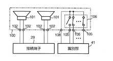
第1に、図11に示すように、外部スピーカ装置100に、その種類ごとに異なる抵抗値の識別抵抗体104を有するようにし、記憶部25は、抵抗値に対応した外部スピーカ用パラメータを複数記憶しておく。そして、識別部41は、測定端子105を介して識別抵抗104の抵抗値を測定して操作部24に出力し、操作部24は、その抵抗値を示す種類情報をパラメータ設定部23に出力する。そして、パラメータ設定部23は、種類情報が示す抵抗値に対応する外部スピーカ用パラメータを記憶部25から読み出して、音質調整部22に設定するようにすればよい。このように識別部41が、外部スピーカ装置100の識別抵抗体104の抵抗値を測定することにより外部スピーカ装置100の種類を識別することができる。 First, as shown in FIG. 11, the
なお、外部スピーカ装置100に対応する抵抗値については、ある程度の抵抗値のばらつきを考慮して、所定の範囲の抵抗値とすればよい。すなわち、記憶部25に記憶される複数の外部スピーカ用パラメータの各々に対応する抵抗値は所定の範囲をもって対応付けられているようにすることが望ましい。また、記憶部25に記憶される外部スピーカ用パラメータは実施形態と同様とし、外部スピーカ装置100の種類と抵抗値とを対応付ける対応テーブルを記憶部25に記憶させて、パラメータ設定部23は、この対応テーブルと種類情報とから読み出すべきパラメータを判断するようにしてもよい。 In addition, the resistance value corresponding to the
また、図12に示すように、識別抵抗体104と直列にLED(Light Emitting Diode)110などの発光素子を設けて、識別抵抗体104を測定しているときに、発光させるようにしてもよい。構成の一例として、識別部41は、識別抵抗体104およびLED110に電流icを供給する定電流源411と、2つの測定端子105間の電圧を測定する電圧判別部412を有するようにすればよい。そして、測定した電圧と電流icから抵抗値を算出すればよい。そして、図3に示すようにLED110を配置すれば、識別抵抗体104の抵抗値を測定中であるか否かを視認できる。なお、識別抵抗体104の抵抗値をLED110の発光時の抵抗値に比べて十分大きくするようにすれば、LED110における電圧降下を無視することができる。また、識別抵抗体104の抵抗値が低い場合には、LED110の発光時の抵抗値を加えた抵抗値が、外部スピーカ装置100の種類を示す抵抗値となるように各抵抗値を設定すればよい。 In addition, as shown in FIG. 12, a light emitting element such as an LED (Light Emitting Diode) 110 may be provided in series with the
第2に、図3に示すように、外部スピーカ装置100に、その種類ごとに異なるバーコード、2次元コードなどの図形107を描画しておくようにしておく。そして、識別部41は、外部スピーカ装置100に描画された図形107をLED、光センサ、CCD(Charge Coupled Device)などを用いたスキャナによって光学的に読み取って、外部スピーカ装置100の種類を識別するようにすればよい。なお、図形と種類との対応は上記のように対応テーブルを用意しておいてもよいし、外部スピーカ用パラメータと図形とを直接対応させるようにしておいてもよい。 Secondly, as shown in FIG. 3, a graphic 107 such as a bar code or a two-dimensional code which is different for each type is drawn on the
第3に、図13に示すように、外部スピーカ装置100に、その種類を識別する識別情報を記憶するフラッシュメモリ、ROM(Read Only Memory)などの識別情報記憶部106を設けておく。そして、識別部41は、この識別情報記憶部106に記憶された識別情報を取得して、外部スピーカ装置100の種類を識別するようにしてもよい。この識別情報が記憶される識別情報記憶部106が、例えば、RFID(Radio Frequency IDentification)技術を用いたタグの記憶手段に記憶されたものとし、識別手段にこのタグの記憶手段に記憶された情報を読み取るリーダを設ければ、無線で識別情報を取得することもできる。 Thirdly, as shown in FIG. 13, the
また、識別情報記憶部106は、図14に示すような構成としてもよい。すなわち、識別情報記憶部106は、複数の測定端子105および基準端子108に接続されている。複数の測定端子105の各々は、基準端子108と短絡状態または開放状態となっている。そして、測定端子105の位置と、各測定端子105に対応する短絡状態と開放状態との組み合わせを、外部スピーカ装置100の種類を識別する識別情報とすればよい。この場合、識別部41は、複数の測定端子105の各々について短絡状態であるか開放状態であるかについて、各測定端子105に微少電流を供給するなどして認識し、その組み合わせによって外部スピーカ装置100の種類を識別するようにすればよい。これにより、例えば測定端子105がn個である場合には、2n種類の外部スピーカ装置100を示すことができる。Further, the identification
上記のように、様々な方法によって外部スピーカ装置100の種類を識別することができる。なお、識別部41は、操作部24のリモコンなどに設けられることで、外部スピーカ装置100の種類を識別する処理を利用者が容易に行うことができる。この場合、リモコンは、無線通信手段を用いて操作部24の受信手段に識別した結果を送信するようにすればよい。また、外部スピーカ装置100に測定端子105が設けられている場合には、テレビ1の接続端子29と外部スピーカ装置100とを接続するラインと、識別部41と測定端子105とを接続するラインとを一つの接続コネクタにまとめて構成し、テレビ1と外部スピーカ装置100との接続を容易なものとしてもよい。 As described above, the type of the
<変形例6>
上述した実施形態において、接続端子29に接続される外部スピーカ装置100の種類に対応する外部スピーカ用パラメータが記憶部25に記憶されていない場合には、外部から取得して、外部スピーカ装置100の種類に対応させて、記憶部25に記憶されるようにしてもよい。この場合には、図15に示すように、様々な外部スピーカ装置100の種類に対応する外部スピーカ用パラメータを取得し、記憶部25に記憶させるデータ取得部40を設ければよい。<Modification 6>
In the above-described embodiment, when the external speaker parameters corresponding to the type of the
データ取得部40は、例えば、必要な外部スピーカ装置100の種類に対応する外部スピーカ用パラメータを、ネットワークを介して配信サーバなどから受信して取得するようにしてもよいし、外部の記憶媒体から読み出して取得するようにしてもよい。また、外部スピーカ装置100が、対応する外部スピーカ用パラメータが記憶された記憶手段を有する場合には、データ取得部40は、外部スピーカ装置100の記憶手段から外部スピーカ用パラメータを読み出して取得するようにすればよい。なお、データ取得部40によって外部スピーカ装置100の種類に対応する外部スピーカ用パラメータを取得することができない場合には、フラットな周波数特性のパラメータが音質調整部22に設定されるようにしてもよい。 For example, the data acquisition unit 40 may receive and acquire external speaker parameters corresponding to the required type of
<変形例7>
上述した実施形態においては、内部スピーカ28および接続端子に供給されるオーディオ信号は、双方同じ増幅部26において増幅されたオーディオ信号であったが、各々異なる増幅部26において増幅されたオーディオ信号を用いてもよい。この場合には、図16に示すように、切替供給部27と内部スピーカ28との間に増幅部26−1、切替供給部27と接続端子29との間に増幅部26−2を設けるようにすればよい。このようにすると、増幅部26−1は、内部スピーカ28に合わせた低出力のアンプとし、増幅部26−2は、様々な外部スピーカ装置100に対応するため、高出力のアンプとすることもできる。<Modification 7>
In the embodiment described above, the audio signals supplied to the
ここで、増幅部26−2については、接続端子29に接続される外部スピーカ装置100の種類によって入力インピーダンスが異なる場合に、入力インピーダンスに対応して出力インピーダンスが変更できるようにしてもよいし、出力インピーダンスごとに異なる接続端子29を設けてもよい。このように出力インピーダンスの変更を行う場合には、外部スピーカ装置100の種類と入力インピーダンスの対応を示す対応テーブルを記憶部25に記憶しておき、増幅部26−2は、操作部24から出力される種類情報と記憶部25に記憶された対応テーブルに基づいて、接続端子29に接続される外部スピーカ装置100の入力インピーダンスを認識するようにすればよい。なお、実施形態における増幅部26についても同様に出力インピーダンスを変更できるようにしてもよい。 Here, for the amplification unit 26-2, when the input impedance differs depending on the type of the
<変形例8>
上述した実施形態における記憶部25に記憶される外部スピーカ用パラメータは、各種類の外部スピーカ装置100について、これを放音させ、周波数特性などの音響特性を測定した測定結果を解析することによって生成したパラメータであってもよいし、外部スピーカ装置100のスピーカ、スピーカ配置、筐体、内部構造などからシミュレーションにより生成されたパラメータであってもよい。すなわち、外部スピーカ用パラメータは、外部スピーカ装置100の固有の周波数特性に基づいて生成されていれば、どのように生成されていてもよく、外部スピーカ装置の種類に対応する専用の外部スピーカ用パラメータとなっていればよい。<Modification 8>
The parameters for external speakers stored in the
<変形例9>
上述した実施形態におけるテレビ1は薄型化により内部スピーカ28の音質が悪化してしまうことになる。音質の向上を行うために、外部スピーカ装置100を設けている。したがって、外部スピーカ装置100の縦、横、奥行きのそれぞれの長さが、テレビ1の筐体50の奥行き(表示面12−Dと垂直方向)より大きいことが望ましい。また、外部スピーカ装置100のスピーカが格納されるエンクロージャの容積は、筐体50などの内部スピーカ28が格納されるエンクロージャの容積よりも広いことが望ましい。<Modification 9>
The sound quality of the
<変形例10>
上述した実施形態におけるテレビ1に接続される外部スピーカ装置100は、例えば図3に示すようなものとしていた。以下、テレビ1に接続される外部スピーカ装置100の他の例について説明する。<
The
第1の例とする外部スピーカ装置100は、図17(a)に示すように、筐体160の上面中心付近に回転台150を有している。この回転台150の上にテレビ1を乗せることにより、テレビ1の表示面12−Dの向きを容易に所望の方向に向けることができる。また、回転台150の中心部に円柱状の開口部151を設けてもよい。図17(b)は、開口部151を有する場合における回転台150の中心軸を通る面での断面形状を示す図である。回転支持部ローラ152は、回転台150と筐体160との間に設けられ、筐体160上で、回転台150を回転させることができるようになっている。また、回転台150の中心軸部分に対応する筐体160には凸部が設けられ、対応するように回転台150には凹部が設けられている。これにより回転軸体52を維持する。 As shown in FIG. 17A, the
そして、テレビ1の支持台51が回転軸体52から取り外しができる構成としておけば、テレビ1の回転軸体52を開口部151に挿入することにより、テレビ1の筐体50を支持することができる。このとき、回転軸体52と回転台150が結合状態となるように、開口部151の内部に回転軸体52と回転台150の相対位置関係を固定するための固定手段を設けるようにしてもよい。なお、回転台150の上面部、または開口部151内の面にテレビ1の接続端子29と接続するためのオーディオ信号入力端子102を設けてもよい。開口部151内の面に設ける場合には、テレビ1の回転軸体52に接続端子29が設けられていることが望ましい。このようにすれば、回転台150を回転してもテレビ1とオーディオ信号入力端子102との相対位置関係が変化しなくなるから、テレビ1と外部スピーカ装置100を接続する接続ケーブルなどの長さに制限されずに回転台150を回転させることができる。 If the
第2の例とする外部スピーカ装置100は、図18(a)に示すように、スピーカ101が1面に設けられた長方体の2つの筐体(以下、筐体170−A、170−Bという)、およびスピーカ101が設けられた面と反対側の面を通じて、この2つの筐体を接続する筐体(以下、筐体170−Cという)から構成されるU字型筐体170を有し、概ねU字型の形状となっている。このような形状とすることにより、テレビ1の支持台51および回転軸体52を避けて設置することができるから、テレビ1が設置されるテレビ台などの上面とテレビ1の筐体50との間にできる空間を有効に利用した外部スピーカ装置100とすることができる。なお、図18(a)においては、筐体170−A、170−Bと筐体170−Cの接続部分は角を持った形状となっているが、概ねU字型になっていればよく、角を落として曲面で接続されていてもよい。 As shown in FIG. 18A, an
このような外部スピーカ装置100は、筐体170−Cの領域に低周波数帯域の音を出力するサブウーファ180を設けることもできる。また、図18(a)に示すように、U字型筐体170の内側の面、すなわち筐体170−Aと筐体170−Bとが対向する各面およびに筐体170−Cにおける当該各面をつなぐ面のいずれかの面に、オーディオ信号入力端子102を設けるようにすることが望ましい。 Such an
さらに、このような外部スピーカ装置100は、図18(b)に示すように、U字型筐体170の下面側の一部に空間を設ける構造として、外部スピーカ装置100の一部を設置面から浮かせる構造とすることにより、テレビ1の支持台51の一部をこの空間に入れることができる。このようにすると、テレビ1の回転軸体52を避けることができる程度の筐体170−Aと筐体170−Bとの距離があればよいから、外部スピーカ装置100を小型化することもできる。また、図18(b)において破線で示すように、筐体170−Cの長さを伸縮させて筐体170−Aと筐体170−Bとの距離を可変とすることができるような伸縮部190を設けてもよい。このようにすると、テレビ1の筐体50、支持台51、回転軸体52の大きさに応じて、適切な大きさに調整することができる。なお、この伸縮部190は、筐体170−A、170−Bに設けられてもよい。 Further, as shown in FIG. 18B, such an
<変形例11>
上述した実施形態においては、映像信号入力部11、表示部12を有するテレビ1であったが、テレビ1の構成のうち映像信号入力部11、表示部12以外の構成を有するオーディオ信号供給装置としてもよい。すなわち、オーディオ信号供給装置、映像信号入力部11および表示部12によりテレビ1が構成されているものとしてもよい。また、オーディオ信号供給装置は、内部スピーカ28を有さず、放音は外部スピーカ装置100から行うものとしてもよい。この場合には、内部スピーカ用パラメータ、切替情報、切替供給部27は用いる必要がない。<
In the embodiment described above, the television 1 has the video
1…テレビ、10…信号出力部、11…映像信号入力部、12…表示部、12−D…表示面、21…オーディオ信号入力部、22…音質調整部、23…パラメータ設定部、24…操作部、25…記憶部、26,26−1,26−2…増幅部、27,31…切替供給部、28…内部スピーカ、29…接続端子、30…第2接続端子、40…データ取得部、41…識別部、411…定電流源、412…電圧判別部、50…筐体、51…支持台、52…回転軸体、100…外部スピーカ装置、101…スピーカ、101−1…ツィータ、101−2…ウーファ、102…オーディオ信号入力端子、103…パラメータ記憶部、104…識別抵抗体、105…測定端子、106…識別情報記憶部、107…図形、108…基準端子、110…LED、150…回転台、151…開口部、152…回転支持部ローラ、160…筐体、170…U字型筐体、170−A,170−B,170−C…筐体、180…サブウーファ、190…伸縮部DESCRIPTION OF SYMBOLS 1 ... Television, 10 ... Signal output part, 11 ... Video signal input part, 12 ... Display part, 12-D ... Display surface, 21 ... Audio signal input part, 22 ... Sound quality adjustment part, 23 ... Parameter setting part, 24 ... Operation unit, 25: storage unit, 26, 26-1, 26-2 ... amplification unit, 27, 31 ... switching supply unit, 28 ... internal speaker, 29 ... connection terminal, 30 ... second connection terminal, 40 ... data acquisition , 41, identification unit, 411, constant current source, 412, voltage determination unit, 50, housing, 51, support base, 52, rotating shaft body, 100, external speaker device, 101, speaker, 101-1 tweeter , 101-2 ... Woofer, 102 ... Audio signal input terminal, 103 ... Parameter storage unit, 104 ... Identification resistor, 105 ... Measurement terminal, 106 ... Identification information storage unit, 107 ... Figure, 108 ... Reference terminal, 110 ... LED , DESCRIPTION OF
Claims (8)
Translated fromJapanese前記表示面の周辺部に配置され、供給されるオーディオ信号を放音する内部スピーカと、
外部スピーカ装置が接続され、供給されるオーディオ信号を当該接続される外部スピーカ装置に出力する接続端子と、
内部スピーカ用パラメータを記憶する第1の記憶手段と、
前記外部スピーカ装置の種類に対応した外部スピーカ装置用パラメータを複数記憶する第2の記憶手段と、
オーディオ信号が入力される入力手段と、
前記入力手段に入力されるオーディオ信号に対して、設定されるパラメータに基づいて音響特性の調整を行う音響特性調整手段と、
前記内部スピーカまたは前記接続端子のいずれかを選択する出力選択手段と、
前記第2の記憶手段に記憶された複数の外部スピーカ装置用パラメータから、一の外部スピーカ装置用パラメータを選択するパラメータ選択手段と、
前記出力選択手段によって前記内部スピーカが選択された場合には、前記第1の記憶手段に記憶された前記内部スピーカ用パラメータを前記音響特性調整手段に設定し、前記接続端子が選択された場合には、前記パラメータ選択手段によって選択された前記外部スピーカ装置用パラメータを前記音響特性調整手段に設定する設定手段と、
前記外部スピーカ装置の設置状況に対応した補正データを複数記憶する第3の記憶手段と、
前記第3の記憶手段に記憶された補正データに対応する設置状況の中から、一の設置状況を選択する操作手段と、
前記操作手段によって選択された設置状況に対応する補正データを選択する補正データ選択手段と、
前記音響特性調整手段に設定されるパラメータを、前記補正データ選択手段によって選択された補正データによって補正するパラメータ補正手段と、
前記出力選択手段によって選択された前記内部スピーカまたは前記接続端子に対して、前記音響特性調整手段により音響特性を調整済みのオーディオ信号を供給する供給手段と
を具備することを特徴とするテレビ。Display means for displaying on the display surface based on the input video signal;
An internal speaker arranged on the periphery of the display surface for emitting a supplied audio signal;
A connection terminal for connecting an external speaker device and outputting the supplied audio signal to the connected external speaker device;
First storage means for storing internal speaker parameters;
Second storage means for storing a plurality of external speaker device parameters corresponding to the type of the external speaker device;
An input means for inputting an audio signal;
An acoustic characteristic adjusting means for adjusting an acoustic characteristic based on a set parameter for an audio signal input to the input means;
Output selecting means for selecting either the internal speaker or the connection terminal;
Parameter selecting means for selecting one external speaker device parameter from a plurality of external speaker device parameters stored in the second storage means;
When the internal speaker is selected by the output selection unit, the internal speaker parameter stored in the first storage unit is set in the acoustic characteristic adjustment unit, and the connection terminal is selected. Setting means for setting the external speaker device parameters selected by the parameter selection means in the acoustic characteristic adjustment means;
Third storage means for storing a plurality of correction data corresponding to the installation status of the external speaker device;
Operating means for selecting one installation situation from the installation situations corresponding to the correction data stored in the third storage means;
Correction data selection means for selecting correction data corresponding to the installation status selected by the operation means;
Parameter correction means for correcting the parameters set in the acoustic characteristic adjustment means by correction data selected by the correction data selection means;
And a supply means for supplying an audio signal whose acoustic characteristics are adjusted by the acoustic characteristics adjusting means to the internal speaker or the connection terminal selected by the output selecting means.
前記パラメータ選択手段は、前記識別手段によって識別された外部スピーカ装置の種類に対応するパラメータを選択する
ことを特徴とする請求項1に記載のテレビ。Further comprising identification means for identifying the type of external speaker device connected to the connection terminal;
The television according to claim 1, wherein the parameter selection unit selects a parameter corresponding to the type of the external speaker device identified by the identification unit.
ことを特徴とする請求項2に記載のテレビ。The said identification means identifies the kind of external speaker apparatus connected to the said connection terminal by measuring the resistance value of the identification resistor provided in the said external speaker apparatus. TV.
ことを特徴とする請求項2に記載のテレビ。The television according to claim 2, wherein the identification unit identifies the type of the external speaker device connected to the connection terminal by optically reading a figure drawn on the external speaker device.
ことを特徴とする請求項2に記載のテレビ。The said identification means identifies the kind of external speaker apparatus connected to the said connection terminal by acquiring the identification information memorize | stored in the memory | storage means of the said external speaker apparatus. TV set.
前記識別手段は、識別した外部スピーカ装置の種類を示す情報を、前記無線通信手段によって前記パラメータ選択手段に対して送信し、
前記パラメータ選択手段は、前記無線通信手段によって送信された情報を受信し、当該情報が示す外部スピーカ装置の種類に対応するパラメータを選択する
ことを特徴とする請求項2乃至請求項5のいずれかに記載のテレビ。The identification means includes wireless communication means,
The identification means transmits information indicating the type of the identified external speaker device to the parameter selection means by the wireless communication means,
The parameter selection unit receives the information transmitted by the wireless communication unit, and selects a parameter corresponding to the type of the external speaker device indicated by the information. TV described in.
内部スピーカ用パラメータを記憶する第1の記憶手段と、
前記外部スピーカ装置の種類に対応した外部スピーカ装置用パラメータを複数記憶する第2の記憶手段と、
オーディオ信号が入力される入力手段と、
前記入力手段に入力されるオーディオ信号に対して、設定されるパラメータに基づいて音響特性の調整を行う音響特性調整手段と、
前記内部スピーカまたは前記接続端子のいずれかを選択する出力選択手段と、
前記第2の記憶手段に記憶された複数の外部スピーカ装置用パラメータから、一の外部スピーカ装置用パラメータを選択するパラメータ選択手段と、
前記出力選択手段によって前記内部スピーカが選択された場合には、前記第1の記憶手段に記憶された前記内部スピーカ用パラメータを前記音響特性調整手段に設定し、前記接続端子が選択された場合には、前記パラメータ選択手段によって選択された前記外部スピーカ装置用パラメータを前記音響特性調整手段に設定する設定手段と、
前記外部スピーカ装置の設置状況に対応した補正データを複数記憶する第3の記憶手段と、
前記第3の記憶手段に記憶された補正データに対応する設置状況の中から、一の設置状況を選択する操作手段と、
前記操作手段によって選択された設置状況に対応する補正データを選択する補正データ選択手段と、
前記音響特性調整手段に設定されるパラメータを、前記補正データ選択手段によって選択された補正データによって補正するパラメータ補正手段と、
前記出力選択手段によって選択された前記内部スピーカまたは前記接続端子に対して、前記音響特性調整手段により音響特性を調整済みのオーディオ信号を供給する供給手段と
を具備することを特徴とするオーディオ信号供給装置。Based on the input video signal, display means for displaying on the display surface, an internal speaker arranged on the periphery of the display surface for emitting the supplied audio signal, and an external speaker device are connected and supplied An audio signal supply device used in a television having a connection terminal for outputting an audio signal to be connected to the external speaker device to be connected,
First storage means for storing internal speaker parameters;
Second storage means for storing a plurality of external speaker device parameters corresponding to the type of the external speaker device;
An input means for inputting an audio signal;
An acoustic characteristic adjusting means for adjusting an acoustic characteristic based on a set parameter for an audio signal input to the input means;
Output selecting means for selecting either the internal speaker or the connection terminal;
Parameter selecting means for selecting one external speaker device parameter from a plurality of external speaker device parameters stored in the second storage means;
When the internal speaker is selected by the output selection unit, the internal speaker parameter stored in the first storage unit is set in the acoustic characteristic adjustment unit, and the connection terminal is selected. Setting means for setting the external speaker device parameters selected by the parameter selection means in the acoustic characteristic adjustment means;
Third storage means for storing a plurality of correction data corresponding to the installation status of the external speaker device;
Operating means for selecting one installation situation from the installation situations corresponding to the correction data stored in the third storage means;
Correction data selection means for selecting correction data corresponding to the installation status selected by the operation means;
Parameter correction means for correcting the parameters set in the acoustic characteristic adjustment means by correction data selected by the correction data selection means;
An audio signal supply comprising: a supply unit configured to supply an audio signal having an acoustic characteristic adjusted by the acoustic characteristic adjustment unit to the internal speaker or the connection terminal selected by the output selection unit. apparatus.
オーディオ信号が入力される入力過程と、
前記入力過程において入力されるオーディオ信号に対して、設定されるパラメータに基づいて音響特性の調整を行う音響特性調整過程と、
前記内部スピーカまたは前記接続端子のいずれかを選択する出力選択過程と、
前記第2の記憶手段に記憶された複数の外部スピーカ装置用パラメータから、一の外部スピーカ装置用パラメータを選択するパラメータ選択過程と、
前記出力選択過程によって前記内部スピーカが選択された場合には、前記第1の記憶手段に記憶された前記内部スピーカ用パラメータを前記音響特性調整過程に設定し、前記接続端子が選択された場合には、前記パラメータ選択過程によって選択された前記外部スピーカ装置用パラメータを前記音響特性調整過程に設定する設定過程と、
前記第3の記憶手段に記憶された補正データに対応する設置状況の中から、一の設置状況を選択する操作過程と、
前記操作手段によって選択された設置状況に対応する補正データを選択する補正データ選択過程と、
前記音響特性調整手段に設定されるパラメータを、前記補正データ選択手段によって選択された補正データによって補正するパラメータ補正過程と、
前記出力選択過程によって選択された前記内部スピーカまたは前記接続端子に対して、前記音響特性調整過程により音響特性を調整済みのオーディオ信号を供給する供給過程と
を備えることを特徴とするオーディオ信号処理方法。Based on the input video signal, display means for displaying on the display surface, an internal speaker arranged on the periphery of the display surface for emitting the supplied audio signal, and an external speaker device are connected and supplied A connection terminal for outputting the audio signal to be connected to the connected external speaker device, a first storage means for storing parameters for the internal speaker, and a plurality of parameters for the external speaker device corresponding to the type of the external speaker device An audio signal processing method used for a television, comprising: a secondstorage unit configured to store a plurality of correction data corresponding to installation conditions of the external speaker device ;
An input process in which an audio signal is input;
An acoustic characteristic adjustment process for adjusting an acoustic characteristic based on a set parameter for an audio signal input in the input process;
An output selection process for selecting either the internal speaker or the connection terminal;
A parameter selection step of selecting one external speaker device parameter from a plurality of external speaker device parameters stored in the second storage means;
When the internal speaker is selected in the output selection process, the internal speaker parameter stored in the first storage means is set in the acoustic characteristic adjustment process, and the connection terminal is selected. A setting process for setting the external speaker device parameter selected in the parameter selection process in the acoustic characteristic adjustment process;
An operation process of selecting one installation situation from the installation situations corresponding to the correction data stored in the third storage means;
A correction data selection process for selecting correction data corresponding to the installation status selected by the operation means;
A parameter correction process for correcting the parameters set in the acoustic characteristic adjusting means by the correction data selected by the correction data selecting means;
An audio signal processing method comprising: supplying an audio signal having an acoustic characteristic adjusted by the acoustic characteristic adjustment process to the internal speaker or the connection terminal selected by the output selection process. .
Priority Applications (1)
| Application Number | Priority Date | Filing Date | Title |
|---|---|---|---|
| JP2007303725AJP5061864B2 (en) | 2007-11-22 | 2007-11-22 | Television, audio signal supply apparatus and audio signal processing method |
Applications Claiming Priority (1)
| Application Number | Priority Date | Filing Date | Title |
|---|---|---|---|
| JP2007303725AJP5061864B2 (en) | 2007-11-22 | 2007-11-22 | Television, audio signal supply apparatus and audio signal processing method |
Publications (2)
| Publication Number | Publication Date |
|---|---|
| JP2009130642A JP2009130642A (en) | 2009-06-11 |
| JP5061864B2true JP5061864B2 (en) | 2012-10-31 |
Family
ID=40821121
Family Applications (1)
| Application Number | Title | Priority Date | Filing Date |
|---|---|---|---|
| JP2007303725AExpired - Fee RelatedJP5061864B2 (en) | 2007-11-22 | 2007-11-22 | Television, audio signal supply apparatus and audio signal processing method |
Country Status (1)
| Country | Link |
|---|---|
| JP (1) | JP5061864B2 (en) |
Families Citing this family (6)
| Publication number | Priority date | Publication date | Assignee | Title |
|---|---|---|---|---|
| KR101089282B1 (en)* | 2009-08-20 | 2011-12-05 | 김서경 | Multi-amp audio module for multichannel speakers and prefabricated multi-amp audio module housing assembly for it |
| JP2015039081A (en)* | 2011-07-29 | 2015-02-26 | 株式会社東芝 | Electronic apparatus, electronic apparatus sound control method, and program |
| JP2014096657A (en)* | 2012-11-08 | 2014-05-22 | Yamaha Corp | Acoustic device |
| TWI599239B (en)* | 2013-06-13 | 2017-09-11 | 群邁通訊股份有限公司 | Amplifying device, portable electronic device and audio playing component |
| US20190158970A1 (en)* | 2015-12-25 | 2019-05-23 | Panasonic Intellectual Property Management Co., Ltd. | Sound reproduction device |
| WO2018173131A1 (en)* | 2017-03-22 | 2018-09-27 | ヤマハ株式会社 | Signal processing device |
Family Cites Families (6)
| Publication number | Priority date | Publication date | Assignee | Title |
|---|---|---|---|---|
| JPH02312370A (en)* | 1989-05-26 | 1990-12-27 | Mitsubishi Electric Corp | Television receiver |
| JP3538035B2 (en)* | 1997-09-12 | 2004-06-14 | パイオニア株式会社 | equalizer |
| JP2005117361A (en)* | 2003-10-08 | 2005-04-28 | Sanyo Electric Co Ltd | Acoustic device,and acoustic characteristic setting method for acoustic device |
| JP4269020B2 (en)* | 2003-12-10 | 2009-05-27 | 京セラ株式会社 | Mobile communication terminal |
| JP2006186571A (en)* | 2004-12-27 | 2006-07-13 | Clarion Co Ltd | Audio apparatus and control method thereof |
| JP2006339908A (en)* | 2005-05-31 | 2006-12-14 | Toshiba Corp | Information processing apparatus and sound output characteristic adjusting method |
- 2007
- 2007-11-22JPJP2007303725Apatent/JP5061864B2/ennot_activeExpired - Fee Related
Also Published As
| Publication number | Publication date |
|---|---|
| JP2009130642A (en) | 2009-06-11 |
Similar Documents
| Publication | Publication Date | Title |
|---|---|---|
| JP2009130643A (en) | Audio signal supplying apparatus, parameter providing system, television set, av system, speaker device and audio signal supplying method | |
| JP5061864B2 (en) | Television, audio signal supply apparatus and audio signal processing method | |
| US10499172B2 (en) | Audio apparatus adaptable to user position | |
| RU2534958C2 (en) | Electronic adapter for selective modification of audio or video data for use with output device | |
| CN103918282B (en) | The method and apparatus for processing audio signal | |
| CN106465031B (en) | Audio device, television receiver and sound signal adjustment method | |
| US7825986B2 (en) | Integrated multimedia signal processing system using centralized processing of signals and other peripheral device | |
| US10788946B2 (en) | Display apparatus, source apparatus, and methods of providing content | |
| JP2006191577A (en) | Integrated multimedia signal processing system using centralized processing of signal | |
| JP2013247456A (en) | Acoustic processing device, acoustic processing method, acoustic processing program, and acoustic processing system | |
| US9733884B2 (en) | Display apparatus, control method thereof, and display system | |
| CN109302525A (en) | A kind of method and multi-screen terminal playing sound | |
| US9241191B2 (en) | Method for auto-setting configuration of television type and television using the same | |
| KR101977329B1 (en) | Method and apparatus for controlling sound signal output | |
| KR101672210B1 (en) | Audio system and method of operating the same | |
| US8953825B2 (en) | Display apparatus and control method thereof | |
| US10992273B2 (en) | Electronic device and operation method thereof | |
| KR102608680B1 (en) | Electronic device and control method thereof | |
| US20220150654A1 (en) | Display device and surround sound system | |
| CN117319888A (en) | Sound effect control method, device and system | |
| CN107995562B (en) | Information processing method and device | |
| KR20240079795A (en) | Cleaner and method for controlling thereof | |
| WO2024211045A1 (en) | Systems and methods for applying equal-loudness correction | |
| KR20040106845A (en) | Message display apparatus for audio mode setting and the method thereof |
Legal Events
| Date | Code | Title | Description |
|---|---|---|---|
| A621 | Written request for application examination | Free format text:JAPANESE INTERMEDIATE CODE: A621 Effective date:20100423 | |
| A131 | Notification of reasons for refusal | Free format text:JAPANESE INTERMEDIATE CODE: A131 Effective date:20120117 | |
| A521 | Request for written amendment filed | Free format text:JAPANESE INTERMEDIATE CODE: A523 Effective date:20120316 | |
| TRDD | Decision of grant or rejection written | ||
| A01 | Written decision to grant a patent or to grant a registration (utility model) | Free format text:JAPANESE INTERMEDIATE CODE: A01 Effective date:20120710 | |
| A01 | Written decision to grant a patent or to grant a registration (utility model) | Free format text:JAPANESE INTERMEDIATE CODE: A01 | |
| A61 | First payment of annual fees (during grant procedure) | Free format text:JAPANESE INTERMEDIATE CODE: A61 Effective date:20120723 | |
| R150 | Certificate of patent or registration of utility model | Ref document number:5061864 Country of ref document:JP Free format text:JAPANESE INTERMEDIATE CODE: R150 Free format text:JAPANESE INTERMEDIATE CODE: R150 | |
| FPAY | Renewal fee payment (event date is renewal date of database) | Free format text:PAYMENT UNTIL: 20150817 Year of fee payment:3 | |
| LAPS | Cancellation because of no payment of annual fees |