JP5060476B2 - System and method for detecting respiratory phase of a patient undergoing radiation therapy - Google Patents
System and method for detecting respiratory phase of a patient undergoing radiation therapyDownload PDFInfo
- Publication number
- JP5060476B2 JP5060476B2JP2008522987AJP2008522987AJP5060476B2JP 5060476 B2JP5060476 B2JP 5060476B2JP 2008522987 AJP2008522987 AJP 2008522987AJP 2008522987 AJP2008522987 AJP 2008522987AJP 5060476 B2JP5060476 B2JP 5060476B2
- Authority
- JP
- Japan
- Prior art keywords
- patient
- radiation
- plan
- transmission data
- images
- Prior art date
- Legal status (The legal status is an assumption and is not a legal conclusion. Google has not performed a legal analysis and makes no representation as to the accuracy of the status listed.)
- Active
Links
Images


Classifications
- A—HUMAN NECESSITIES
- A61—MEDICAL OR VETERINARY SCIENCE; HYGIENE
- A61N—ELECTROTHERAPY; MAGNETOTHERAPY; RADIATION THERAPY; ULTRASOUND THERAPY
- A61N5/00—Radiation therapy
- A61N5/10—X-ray therapy; Gamma-ray therapy; Particle-irradiation therapy
- A—HUMAN NECESSITIES
- A61—MEDICAL OR VETERINARY SCIENCE; HYGIENE
- A61N—ELECTROTHERAPY; MAGNETOTHERAPY; RADIATION THERAPY; ULTRASOUND THERAPY
- A61N5/00—Radiation therapy
- A61N5/10—X-ray therapy; Gamma-ray therapy; Particle-irradiation therapy
- A61N5/1048—Monitoring, verifying, controlling systems and methods
- A61N5/1049—Monitoring, verifying, controlling systems and methods for verifying the position of the patient with respect to the radiation beam
- A61N2005/1061—Monitoring, verifying, controlling systems and methods for verifying the position of the patient with respect to the radiation beam using an x-ray imaging system having a separate imaging source
- A—HUMAN NECESSITIES
- A61—MEDICAL OR VETERINARY SCIENCE; HYGIENE
- A61N—ELECTROTHERAPY; MAGNETOTHERAPY; RADIATION THERAPY; ULTRASOUND THERAPY
- A61N5/00—Radiation therapy
- A61N5/10—X-ray therapy; Gamma-ray therapy; Particle-irradiation therapy
- A61N5/1042—X-ray therapy; Gamma-ray therapy; Particle-irradiation therapy with spatial modulation of the radiation beam within the treatment head
- A—HUMAN NECESSITIES
- A61—MEDICAL OR VETERINARY SCIENCE; HYGIENE
- A61N—ELECTROTHERAPY; MAGNETOTHERAPY; RADIATION THERAPY; ULTRASOUND THERAPY
- A61N5/00—Radiation therapy
- A61N5/10—X-ray therapy; Gamma-ray therapy; Particle-irradiation therapy
- A61N5/1048—Monitoring, verifying, controlling systems and methods
- A61N5/1064—Monitoring, verifying, controlling systems and methods for adjusting radiation treatment in response to monitoring
- A61N5/1065—Beam adjustment
- A61N5/1067—Beam adjustment in real time, i.e. during treatment
Landscapes
- Health & Medical Sciences (AREA)
- Engineering & Computer Science (AREA)
- Biomedical Technology (AREA)
- Pathology (AREA)
- Nuclear Medicine, Radiotherapy & Molecular Imaging (AREA)
- Radiology & Medical Imaging (AREA)
- Life Sciences & Earth Sciences (AREA)
- Animal Behavior & Ethology (AREA)
- General Health & Medical Sciences (AREA)
- Public Health (AREA)
- Veterinary Medicine (AREA)
- Radiation-Therapy Devices (AREA)
- Apparatus For Radiation Diagnosis (AREA)
- Magnetic Resonance Imaging Apparatus (AREA)
Abstract
Description
Translated fromJapanese本出願は、ともに参照によって本明細書に組み込まれる2005年7月22日出願の「SYSTEM AND METHOD OF DELIVERING RADIATION THERAPY TO A MOVING TARGET(移動ターゲットへ放射療法を施すシステムおよび方法)」という名称の米国特許仮出願第60/701541号、および2005年7月22日出願の「SYSTEM AND METHOD FOR FEEDBACK GUIDED QUALITY ASSURANCE AND ADAPTATIONS TO RADIATION THERAPY TREATMENT(放射療法治療へのフィードバック誘導品質保証および適用のためのシステムおよび方法)」という名称の米国特許仮出願第60/701580号の恩典を主張するものである。 This application is a United States application entitled “SYSTEM AND METHOD OF DELIVERING THERAPY TO A MOVING TARGET”, filed July 22, 2005, both incorporated herein by reference. Patent Provisional Patent Application No. 60/701541 and “SYSTEM AND METHOD FOR FEEDBACK GUIDED QUALITY ASSURANCE AND ADAPTATIONS TO RADIATION THERAPY TREATMENT for quality assurance and feedback to radiation therapy treatment US Patent Provisional Application No. 60/7015 entitled "Method)" Which claims the No. 0 of benefits.
最近、放射線療法の実践には、コンピュータおよびネットワーク化、放射線療法治療計画作成ソフトウェア、ならびに医療用画像化様式(コンピュータ断層撮影法(「CT」)、磁気共鳴画像法(「MRI」)、超音波法(「US」)、陽電子放射断層撮影法(「PET」)など)における改良が組み入れられてきた。場合によっては、放射線療法の計画作成および引渡しのための技法が使用される。例えば、肺の腫瘍など、移動するターゲットを治療するある方法は、ターゲットが指定された軌道窓の中にあるときにだけ、放射線を「ゲーティング」すなわち放出することを含む。この方法は、周期的時間間隔の間だけターゲットに照射されるため、非効率である。 Recently, radiation therapy practice includes computer and networking, radiation therapy treatment planning software, and medical imaging formats (computed tomography (“CT”), magnetic resonance imaging (“MRI”), ultrasound, Improvements in methods ("US"), positron emission tomography ("PET", etc.) have been incorporated. In some cases, techniques for radiotherapy planning and delivery are used. For example, one method of treating a moving target, such as a lung tumor, includes “gating” or emitting radiation only when the target is within a specified trajectory window. This method is inefficient because the target is illuminated only during periodic time intervals.
移動するターゲットを治療する別の1つの方法は、呼吸同期照射法(「BSD」)と呼ばれる。この技法は、治療中にターゲットがたどると予想されるトラック、すなわち予想される運動経路を利用する。そうするために、ターゲットがこの予想されるトラック上にとどまると仮定した計画が作成され、これは、治療計画の全体にわたって予想される周期および位相を有する。厳密に定義されたトラックに従うよう患者に促す音声および視覚誘導を使用することができる。しかし、放射線療法の患者の大部分にとって、厳密に定義されたパターンに従うことは難しい。 Another method of treating a moving target is called breath-synchronized irradiation (“BSD”). This technique takes advantage of the track that the target is expected to follow during treatment, i.e., the expected path of motion. To do so, a plan is created assuming that the target remains on this expected track, which has the expected period and phase throughout the treatment plan. Audio and visual guidance that prompts the patient to follow a strictly defined track can be used. However, for most radiation therapy patients, it is difficult to follow a strictly defined pattern.
領域の位置、周期および位相についてのプリオリ知識に依存することなく、移動する関心領域に放射線を放出することができる。患者の解剖学的運動の変化を反映させ、放射線治療をより効果的に適用するために、複数の計画間の動的切替え、または「治療中(on the fly)」の計画作成を使用することができる。 Radiation can be emitted to a moving region of interest without relying on priori knowledge about the position, period and phase of the region. Use dynamic switching between plans, or “on the fly” planning, to reflect changes in patient anatomy and more effectively apply radiation therapy Can do.
一実施形態では、本発明は、放射線療法を受けている患者の呼吸位相を検出する方法を提供する。この方法は、呼吸サイクルの位相を表す複数の患者画像を取得するステップと、患者に放射線を放出するステップと、放射線を放出するステップ中に、患者の伝送データを収集するステップと、伝送データを複数の患者画像と比較するステップとを含む。 In one embodiment, the present invention provides a method for detecting the respiratory phase of a patient undergoing radiation therapy. The method includes acquiring a plurality of patient images representing a phase of a respiratory cycle, emitting radiation to the patient, collecting patient transmission data during the radiation emitting step, and transmitting the transmission data. Comparing with a plurality of patient images.
他の実施形態では、本発明が、放射線療法を受けている患者の呼吸位相を検出するシステムを提供する。このシステムは、コンピュータプロセッサ、患者に放射線を放出するように動作可能な放射線源、および透過放射線を収集するように動作可能な放射線検出器を含む放射線療法装置を含む。このシステムはさらに、コンピュータプロセッサがアクセス可能なコンピュータ可読媒体に記憶されたソフトウェアプログラムを含む。このソフトウェアプログラムは、呼吸サイクルの位相を表す複数の患者画像を取得し、前記収集された透過放射線から前記患者の伝送データを取得し、前記伝送データを前記複数の患者画像と比較するように動作可能である。 In another embodiment, the present invention provides a system for detecting the respiratory phase of a patient undergoing radiation therapy. The system includes a radiation therapy device including a computer processor, a radiation source operable to emit radiation to a patient, and a radiation detector operable to collect transmitted radiation. The system further includes a software program stored on a computer readable medium accessible to the computer processor. The software program is operable to obtain a plurality of patient images representing a phase of a respiratory cycle, obtain transmission data of the patient from the collected transmitted radiation, and compare the transmission data with the plurality of patient images. Is possible.
本発明のその他の形態は、以下の詳細な説明および添付図面を検討することによって明らかとなろう。 Other aspects of the invention will become apparent by consideration of the following detailed description and accompanying drawings.
本発明の実施形態を詳細に説明する前に、本発明は、その適用において、以下の説明に記載された、または添付図面に示された構造および構成要素の配置の詳細に限定されないことを理解されたい。本発明は他の実施形態を有することができ、様々な方法で実践し、または実施することができる。さらに、本明細書で使用される語句および用語は、説明を目的としたものであり、それらを、限定するものと考えるべきではないことを理解されたい。「含む」、「備える」または「有する」およびそれらの変形の使用は以後に記載された項目およびそれらの均等物、ならびに追加の項目を包含することを意味する。特に指定されまたは限定されない限り、用語「取り付けられた」、「接続された」、「支持された」および「結合された」ならびに本明細書中のそれらの変形は幅広く使用され、直接と間接の両方の取付け、接続、支持および結合を包含する。さらに、「接続された」および「結合された」は、物理的または機械的な接続または結合に限定されない。 Before describing embodiments of the present invention in detail, it is understood that the present invention is not limited in its application to the details of construction and the arrangement of components set forth in the following description or illustrated in the accompanying drawings. I want to be. The invention may have other embodiments and may be practiced or carried out in various ways. Further, it should be understood that the terms and terms used herein are for illustrative purposes and should not be considered limiting. Use of “including”, “comprising” or “having” and variations thereof is meant to encompass the items listed thereafter and their equivalents, as well as additional items. Unless otherwise specified or limited, the terms “attached”, “connected”, “supported” and “coupled” and variations thereof herein are widely used, both direct and indirect Includes both attachment, connection, support and coupling. Further, “connected” and “coupled” are not limited to physical or mechanical connections or couplings.
本明細書では、図面を説明する際に、上、下、下方、上方、後方、底、前、後など、方向について言及される場合があるが、これらの言及は、便宜上、(普通に見たときの)図面に対してなされる。これらの方向は、文字通りに解釈されることを意図したものではなく、また、任意の形態に本発明を限定することを意図したものでもない。さらに、「第1」、「第2」、「第3」などの用語は、本明細書では説明の目的で使用され、相対的な重要性または有意性を指示しまたは暗示することを意図したものではない。 In this specification, in describing the drawings, reference may be made to directions, such as top, bottom, bottom, top, back, bottom, front, back, etc .; To the drawing. These directions are not intended to be interpreted literally, nor are they intended to limit the invention to any form. Furthermore, terms such as “first”, “second”, “third” are used herein for purposes of explanation and are intended to indicate or imply relative importance or significance. It is not a thing.
さらに、本発明の実施形態は、両方のハードウェア、ソフトウェア、電子構成要素またはモジュールを含み、それらは、議論の目的上、あたかも大部分の構成要素が単にハードウェアとして実現されるように図示され、説明されることがあることを理解された。しかし、当業者は、この詳細な説明を読むことによって、少なくとも1つの実装では、本発明の電子ベースの諸態様をソフトウェアとして実装することができることを理解するであろう。そのため、ハードウェアおよびソフトウェアベースの複数の装置、ならびに複数の様々な構造構成要素を利用して、本発明を実装することができることに留意されたい。さらに、後の段落で説明するように、図面に示された特定の機械的構成は、本発明の実施形態を例示することを意図したものであり、他の代替の機械的構成が可能である。 Furthermore, embodiments of the present invention include both hardware, software, electronic components or modules that are illustrated for the purposes of discussion as if most of the components were simply implemented as hardware. Understand that there may be an explanation. However, one of ordinary skill in the art will understand from reading this detailed description that in at least one implementation, the electronic-based aspects of the present invention can be implemented as software. Thus, it should be noted that the present invention can be implemented using multiple hardware and software based devices and multiple different structural components. Further, as will be described in later paragraphs, the specific mechanical configurations shown in the drawings are intended to exemplify embodiments of the invention, and other alternative mechanical configurations are possible. .
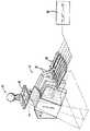
図1は、患者14に放射線療法を提供することができる放射線療法治療システム10を示す。放射線療法治療は、光子ベースの放射線療法、近接照射療法、電子線療法、陽子、中性子または粒子療法、あるいは他のタイプの治療法を含むことができる。放射線療法治療システム10は、ガントリ22を有する放射線療法装置18を含む。図面に示されたガントリ22は環形ガントリであり、すなわち360°の弧を描いて延び、完全な環または円を形成しているが、他のタイプの取付け構成を使用することもできる。例えば、C字型、部分環ガントリまたはロボットアームを使用することができる。 FIG. 1 shows a radiation
ガントリ22は、光子放射線ビーム34を生成するように動作可能な放射線源26と直線加速器30とを有する放射線モジュールを支持することができる。この放射線モジュールはさらに、放射線ビーム34を変更または変調するように動作可能な変調装置42を含むことできる。変調装置42は、放射線ビーム34を変調し、放射線ビーム34を患者14に向かって導く。具体的には、患者の一部分に向かって放射線ビーム34が導かれる。広く言えば、この患者の一部分には全身が含まれるかもしれないが、この部分は一般的には全身よりも小さく、2次元の面積および/または3次元の体積によって定義することができる。ターゲットまたはターゲット部位(54として示されている)と呼ぶことができる放射線を受け取らせたい部分は、関心領域の一例である。他のタイプの関心領域は危険を伴う領域である。ある1つの部分が危険を伴う領域を含む場合、放射線ビームは、その危険を伴う領域からそらされることが好ましい。患者14は、放射線療法を受け取る必要があるターゲット部位54を2つ以上有することがある。このような変調は時に、強度変調放射線療法(「IMRT」)と呼ばれる。 The
放射線モジュールを患者14に対して様々な回転方向位置および/または軸方向位置に配置することができる他の枠組みを使用してもよい。さらに、放射線モジュールは、ガントリ22の形状に従わない経路上を移動してもよい。例えば、図示されたガントリ22が全体に円形であるとしても、放射線モジュールは非円形経路上を移動することができる。 Other frameworks that allow the radiation module to be positioned at various rotational and / or axial positions relative to the
図2に示された一構造では、変調装置42がコリメーション装置を含む。このコリメーション装置は、一組のジョーを有する1次コリメータ38を含む。これらのジョーは、放射線ビームが通過することができる開口を画定し、この開口のサイズを調整する。このコリメーション装置はさらに、マルチリーフコリメータ(MLC)を含み、このMLCは、強度変調を提供するためにある位置から別の位置へ移動するように動作可能なインタレースされた複数のリーフ50を含む。リーフ50はまた、最小限に開いた位置と最大限に開いた位置との間のどの位置へも移動することができることに留意されたい。インタレースされた複数のリーフ50は、放射線ビーム34が患者14のターゲット54に到達する前に、放射線ビーム34の強度、サイズおよび形状を変調する。放射線の通過を許しまたは妨げるために各リーフ50を高速に開閉できるように、各リーフ50は、モータまたは空気弁など、アクチュエータ58によって独立に制御される。アクチュエータ58は、コンピュータ62および/またはコントローラによって制御することができる。 In one structure shown in FIG. 2, the
放射線療法治療システム10はさらに、放射線モジュールからまたは別個の放射線源から放射線ビームを受け取るように動作可能な検出器66、例えばキロボルテージまたはメガボルテージ検出器を含むことができる。放射線モジュールおよび検出器66は潜在的に、患者14のCT画像を生成するコンピュータ断層撮影(CT)システムとして動作することができる。放射線モジュールは、患者14のターゲット54に向かって放射線ビーム34を発射する。これらのCT画像は、扇形幾何形状、マルチスライス形幾何形状または円錐ビーム形幾何形状を有する放射線ビーム34を使用して取得することができる。さらに、CT画像は、メガボルテージエネルギーまたはキロボルテージエネルギーを引渡す直線加速器30を使用して取得することもできる。ターゲット54および周囲組織はこの放射線の一部を吸収する。 The radiation
放射線療法治療システム10はさらに、治療台70(図1に示されている)など、患者14を支持する患者サポートを含むことができる。治療台70は、少なくとも一軸に沿ってx、yまたはz方向に移動する。他の構造では、この患者サポートを、患者の体の任意の部分を支持するように適合された装置とすることができ、この患者サポートは、患者の全身を支持しなければならない装置に限定されない。システム10はさらに、治療台70の位置を操作するように動作可能な駆動システム74を含むことができる。駆動システム74はコンピュータ62によって制御することができる。 The radiation
コンピュータ62は、様々なソフトウェアプログラムおよび/または通信アプリケーションを実行するオペレーティングシステムを含む。具体的には、コンピュータ62は、放射線療法装置18と通信するように動作可能なソフトウェアプログラム78を含むことができる。コンピュータ62は、医療従事者によってアクセスされるように適合された適切な任意の入出力装置を含むことができる。コンピュータ62は、プロセッサ、I/Oインターフェース、記憶装置ないしメモリなどのハードウェアを含むことができる。コンピュータ62はさらに、キーボードやマウスなどの入力装置を含むことができる。コンピュータ62はさらに、モニタなどの出力装置を含むことができる。さらに、コンピュータ62は、プリンタやスキャナなどの周辺装置を含むことができる。
図3に示されているように、放射線療法装置18は、コンピュータ62と直接に通信し、かつ/またはネットワーク82を介して通信する。放射線療法装置18は、ネットワーク82を介して、他の放射線療法装置18とも通信することができる。同様に、それぞれの放射線療法装置18のコンピュータ62は、他の放射線療法装置18のコンピュータ62と通信することができる。コンピュータ62および放射線療法装置18はさらに、データベース86およびサーバ90と通信することができる。複数のデータベース86およびサーバ90がネットワーク82と通信することができる。ソフトウェアプログラム78はサーバ90上に存在することもできることに留意されたい。 As shown in FIG. 3, the
ネットワーク82は、任意のネットワーク化技術またはネットワーク化トポロジ、あるいはネットワーク化技術とトポロジの組合せに従って構築することができ、複数のサブネットワークを含むことができる。図3に示されたコンピュータ62と装置18の間の接続は、ローカルエリアネットワーク(「LAN」)、ワイドエリアネットワーク(「WAN」)、公衆電話交換網(「PSTN」)、無線ネットワーク、イントラネット、インターネットまたは他の適切なネットワークを介して実施することができる。病院または医療施設では、図3に示されたコンピュータ62と装置18の間の接続を、任意のバージョンおよび/または他の必要なプロトコルを有する、ヘルスレベルセブン(「HL7」)プロトコルまたは他のプロトコルを介して実施することができる。HL7は、健康管理環境における電子データ交換用の、ベンダが異なる2つのコンピュータアプリケーション(送信側と受信側)間のインターフェースの実施態様を指定する標準プロトコルである。HL7は、健康管理機関が、異なるアプリケーションシステムに由来する鍵となるデータセットを交換することを可能にする。具体的には、HL7は、交換されるデータ、相互交換のタイミング、およびアプリケーションへのエラーの伝達を定義することができる。フォーマットは一般に、事実上総称的であり、必要とするアプリケーションの要求を満たすように構成することができる。 The
図3に示されたコンピュータ62と放射線療法装置18との間の通信は、任意のバージョンおよび/または他の必要なプロトコルを有する医用画像通信規格(Digital Imaging and Communications in Medicine(医学におけるデジタル描写法および通信):「DICOM」)プロトコルによって実施することもできる。DICOMは、アメリカ電気製造業者協会(「NEMA」)によって策定された、異なる医療機器間で医療用画像関連データを引渡すのに使用されるフォーマットを定義した国際通信規格である。DICOM RTは、特に放射線療法データを対象とした規格を指す。 The communication between the
図3の双方向の矢印は概して、ネットワーク82と、任意の1つのコンピュータ62、放射線療法装置18および図3に示された他の構成要素との間の双方向通信および双方向情報転送を表す。しかし、医療機器によっては、一方向通信および一方向情報転送だけしか必要がない場合もある。 The bi-directional arrows in FIG. 3 generally represent bi-directional communication and bi-directional information transfer between the
様々な条件および関心領域に対応するために、前述のマルチリーフコリメータは、放射線ビーム34の強度変調を提供することができる。より具体的には、マルチリーフコリメータ46のリーフ50を移動することによって、放射線ビーム34の強度を増大または低減させることができる。しかし、動いているターゲット54(例えば、肺、心臓、消化トラックなどの腫瘍)は、しばしば繰返しパターンでは移動しないため、連続ビーム34で治療するのが難しい。 To accommodate various conditions and regions of interest, the multi-leaf collimator described above can provide intensity modulation of the
後述するように、ソフトウェアプログラム78は、患者14に引渡しされる放射線量を、関心領域の実際の運動に従って変更することによって、移動する関心領域に対応することができる。本発明の一実施形態に基づく例示的なソフトウェアプログラム78が、図4に概略的に示されている。このソフトウェアプログラムは、関心領域の位置、周期および位相についての演繹的な知識に依存することなく関心領域に放射線を放出する1つの解決策を提示する。1つの方法は、一群の放出計画の事前生成、および患者の解剖学的運動の変化を反映させるための計画間の機能的切替えを利用する。 As will be described below, the
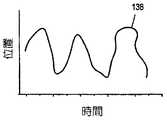
一実施態様は、最初に、ターゲットの軌道、呼吸の位相および治療全体の周期を仮定したBSD型の治療を最適化する。しかし、その1つの計画を最適化することに加えて、基本となるBSD計画とは異なる周期、呼吸位相または他のパラメータをそれぞれが潜在的に有する追加の計画セットを最適化することができる。次いで、治療中に、患者は最初に、BSD計画に示されたターゲットトレースに従うことを試みる。しかし、患者の呼吸が、指定されたしきい値を超えてこの計画から逸脱した場合には、その計画は自動的に、その時点の部位パラメータにより一致した1つの代替計画に切り替わる。患者の随意の呼吸トレースに対する引渡しが、図7の太線に示されている。したがって、この方法の1つの利益は、自動エラー訂正を有するBSD品質の引渡しが可能であり、患者に課せられる運動再現要求が低いことである。 One embodiment initially optimizes a BSD-type treatment that assumes the target trajectory, the phase of respiration, and the overall treatment period. However, in addition to optimizing that one plan, additional set of plans, each potentially having a different period, respiratory phase or other parameters than the underlying BSD plan, can be optimized. Then, during treatment, the patient first tries to follow the target trace indicated in the BSD plan. However, if the patient's breathing deviates from this plan beyond a specified threshold, the plan automatically switches to one alternative plan that is more consistent with the current site parameters. Delivery for the patient's optional breath trace is shown in bold lines in FIG. Thus, one benefit of this method is that it can deliver BSD quality with automatic error correction, and the motion reproduction requirements imposed on the patient are low.
他の実施態様では、基本の4次元(「4D」)計画に従うのではなく、引渡し中に患者が自由に呼吸すると、計画が自動的に切り替わる。所望ならば、咳などの特に不規則な呼吸を識別することができ、呼吸が指定された許容範囲に再び戻るまで、治療を一時的に遅らせることができる。同様に、関心領域の位置が明確に定義されていない呼吸位相または運動部位がある場合には、それらの位相の間、治療を意図的に回避することができる。このような判断は、計画作成時に実施することができるが、患者の解剖学的生理構造の知覚された変化に基づいて動的に実施することもできる。 In other embodiments, instead of following a basic four-dimensional (“4D”) plan, the plan automatically switches as the patient breathes freely during delivery. If desired, particularly irregular breathing, such as coughing, can be identified and treatment can be temporarily delayed until breathing returns to the specified tolerance. Similarly, if there are respiratory phases or motion sites where the location of the region of interest is not clearly defined, treatment can be intentionally avoided during those phases. Such a determination can be made at the time of planning, but can also be made dynamically based on perceived changes in the patient's anatomical physiology.
可能な様々な基準を使用して一連の計画が作成される。必要なときにいつでも転送されるように、これらのすべての計画、またはそれらの多くの可能な組合せがシステム10上に保持される。呼吸パターンは、適切な評価装置によって、リアルタイム判断に基づいて評価され、潜在的には、前の評価に関連して、予想される呼吸シナリオに基づいて評価される。システム10は、計画または計画の組合せを評価し、引渡しすべき計画または計画の組合せを選択する。選択された計画は、以前に施された治療の以前のフラクションまたは部分とともに蓄積することができる。その計画が転送されると、情報を記録する(または例えばリアルタイム線量再構成に関連して使用する)ことができ、潜在的には、この情報が、(その時点のセッションまたは将来のセッションの間に)将来の放射線を放出する計画を改良するために使用される。 A series of plans are created using the various criteria possible. All these plans, or many possible combinations thereof, are kept on the
図4は、ソフトウェアプログラム78とともに使用することができる様々なモジュールを開示する。これらのモジュールには、最適化モジュール95、計画選択モジュール142、取得モジュール94、受渡しモジュール97、患者フィードバックモジュール100および品質保証モジュール146が含まれる。次に、これらのモジュールの様々な実施態様が記載される。しかし、システム10のすべての構成で、これらのモジュールがすべて必要というわけではないこと、および図4に示されていない他のモジュールをソフトウェアプログラム78とともに使用することができることを理解されたい。また、これらのモジュールを結合して、図示された数よりも少ない数のモジュールとすることができること、それぞれのモジュールは、本明細書の説明の中に開示されていない追加の材料を含むことができること、およびモジュールの名称は説明を容易にするためのものであることは明白である。 FIG. 4 discloses various modules that can be used with
A.最適化モジュール
前述のとおり、1つの最適化法は、異なる運動位相(または周期など)をそれぞれが表す4D計画のセットを最適化する方法である。呼吸サイクルは、無限または有限フーリエ展開によって記述し、かつ/または近似することができる。最適化モジュールの95の可能な1つの実施態様では、特定の1つの呼吸サイクルが、時間どおりに変化する、異なる周波数、振幅、位相などを有する正弦型および余弦型関数の線形結合の時間の関数として記述される(例えば図7参照)。この条件下で、最適化モジュール95は、それぞれが特定の時刻の引渡しに対して許容される1つの計画を表す一組の計画を生成する。それらの計画または計画の組合せを使用可能にすることによって、より複雑な「規則正しい」または「不規則な」呼吸パターンに対する引渡しを生成することができる。A. Optimization Module As mentioned above, one optimization method is a method for optimizing a set of 4D plans, each representing a different motion phase (or period, etc.). The respiratory cycle can be described and / or approximated by an infinite or finite Fourier expansion. In one possible implementation of the
最適化モジュール95の他の実施態様では、それぞれの計画が、所与のパラメータ(例えば周期または軌道)に対する完全な4D計画を表す必要はないが、計画のセットがそれぞれ、運動サイクルの単一の位相に対して適切な静的引渡しを表す。関心領域がその異なる運動位相間で移動すると、計画は自動的に切り替わるであろう。同様に、より多くの画像を生成し、より多くの位相計画を最適化し、かつ/または特定の位相に対する計画を選択するために、位相間を補間することも可能である。 In other implementations of the
さらに、所与の位相またはパラメータのセットに対して使用可能な、異なる最適化基準を利用した複数の計画を有することが可能である。例えば、呼吸位相ごとに計画を1つだけ最適化するのではなしに、複数の計画セットを最適化することが可能である。これは、呼吸位相ごとに、余裕が小さい1つの計画と、より余裕の幅の広い(または他の制約が変化する)他の計画を有することを伴うかもしれない。治療が進むにつれて、関心領域の位置、周期および/または位相、ならびにその速度、不確実性および/または変形に基づいて、計画を動的に選択することができる。ターゲット54が明確に定義されている場合には、余裕の幅が狭いセットから計画を動的に選択することができ、確実性が低い場合には、余裕が大きな計画を選択することができる。 In addition, it is possible to have multiple plans utilizing different optimization criteria that can be used for a given phase or set of parameters. For example, rather than optimizing only one plan for each respiratory phase, it is possible to optimize multiple plan sets. This may involve having one plan with less margin and another plan with more margin (or other constraints change) for each respiratory phase. As treatment progresses, the plan can be selected dynamically based on the location, period and / or phase of the region of interest and its speed, uncertainty and / or deformation. When the
複数の位相画像にわたって線量を最適化する1つの方法は、最適化モジュール95が、位相ごとに線量ビームレットを計算し、次いで、画像を関係づける画像変形マップに従ってビームレットを変形させる方法である。この方法を適用することができるが、線量は位相ごとに計算することができ、次いで、変形が調整されたビームレットが必要ないように、変形を使用して追加することができるので、この方法は必要ない。 One way of optimizing dose across multiple phase images is where
B.計画選択モジュール
計画を選択する方法は、いくつかの可能な基準に基づくことができる。計画選択モジュール142の一実施態様では、計画が、関心領域の位置、周期および/または位相などの先に論じた基準に基づき、これらの基準はそれぞれ、運動検出装置89および取得モジュール94によって取得することができる。同様に、不確実性および/または解剖学的情報も組み込むことができる。測定値は、カメラシステム、レーザシステム、X線または透視システム、CT、MRI、PET、単一光子放射形コンピュータ断層撮影(「SPECT」)、オンラインCT、円錐ビームCT、埋込みマーカ、高周波(「RF」)ローカライザ、超音波、呼吸ベルトまたはカフ、埋込みX線源、音響センサ、歪みゲージ、RFエミッタおよび電極に基づくインピーダンス測定などの適用可能な装置から取得される。ただし、適用可能な装置はこれらに限定されるわけではない。B. The method of selecting aplan selection module plan can be based on several possible criteria. In one implementation of the
他の実施態様では、計画選択モジュール142が、線量測定特性に基づいて計画を選択する。より具体的には、最適化された計画セクションごとに所望の線量分布が定義される。次いで、治療中に、計画選択モジュール142が、患者のその時点の解剖学的情報およびターゲット情報を与えられた場合に、使用可能な計画のうちのどの計画が、計画線量と最もよく一致するのかを決定する。この計算は、リアルタイム線量計算を含むことができるが、単純化された計算または予め計算された計算によって近似することもできる。 In other implementations, the
他の実施態様では、計画選択モジュールが、予め計算された計算を使用した変形を組み込む。この実施態様は、物理空間内の線量を特定の組織/ターゲット内の線量に関係づける。変形を組み込むことによって、特定の部位における意図された線量分布と一致する計画の選択がより容易になる。変形技法および計算の例が、その内容の全体が参照によって本明細書で組み込まれる、2005年7月22日出願の「SYSTEM AND METHOD FOR FEEDBACK GUIDED QUALITY ASSURANCE AND ADAPTATIONS TO RADIATION THERAPY TREATMENT(放射療法治療へのフィードバック誘導品質保証および適用のためのシステムおよび方法)」という名称の米国特許仮出願第60/701580号に記載されている。 In other embodiments, the plan selection module incorporates variations using pre-calculated calculations. This embodiment relates the dose in physical space to the dose in a particular tissue / target. Incorporating variations makes it easier to select a plan that matches the intended dose distribution at a particular site. Examples of deformation techniques and calculations are incorporated herein by reference in their entirety, to the “SYSTEM AND METHOD FOR FEEDBACK GUIDED QUALITY ASSURANCE AND ADAPTATIONS TO RADIATION THERAPY THERAPY TREATMENT THERAPY” filed Jul. 22, 2005. System and Method for Feedback-Guided Quality Assurance and Application of US Patent Application No. 60/701580].
なお変形を伴う可能性がある他の実施態様では、所望の線量を計画線量に一致させようとするだけでなく、計画選択モジュール142は同時に、以前のフラクションまたは引渡し中のフラクションの初期との線量の不一致を矯正しようとする。 In other embodiments that may still be distorted, in addition to trying to match the desired dose to the planned dose, the
計画選択モジュール142の他の実施態様では、動的計画選択が、単に線量分布(または累積線量分布、変形線量分布、あるいは変形累積線量分布)との一致だけに基づくのではなく、ターゲット線量、敏感な構造の線量または線量−体積ヒストグラム(「DVH」)などの他の基準も使用する。同様に、計画選択はさらに、所与の生物学的結果を達成することに基づく。この実施態様では、生物学的推定量が、線量累積および/または計画選択プロセスに組み込まれる。計画選択モジュール142はさらに、より攻撃的な計画がより許容されると思われる部位、時刻または患者におけるそれらの使用、およびより敏感な位置、時刻または患者におけるより保守的な計画の使用を容易にするために、患者に関する生物学的および臨床的なフィードバックを組み込むことができる。 In other implementations of the
計画選択モジュールの動的計画選択は、患者のその時点の情報に基づく必要があるだけでなく、測定の遅れを考慮し、解剖学的変化の適切な予期の下に計画を引渡しして、測定および処理における遅延を補償するため、過去の情報を使用することもできる。 The dynamic plan selection of the plan selection module not only needs to be based on the patient's current information, but also takes into account measurement delays and delivers the plan with proper expectation of anatomical changes And past information can also be used to compensate for delays in processing.
ソフトウェアプログラム78の他の実施態様では、動的に選択可能な計画の一部または全部が事前に最適化されない。高速最適化プログラムを使用して、これらの計画のいくつかは、放射線療法の適用中に生成される。同様に、生理学的変化または解剖学的変化を反映させるために、放射線療法の適用中に既存の計画が変更される。言い換えると、最適化モジュール95と計画選択モジュール142は密接に相互作用して(または統合されて)、高速最適化プログラムおよび選択モジュールを提供する。 In other implementations of the
C.機械的追跡サブモジュールを含む取得モジュール
患者の呼吸位相または運動状態の追跡は、多数ある運動検出装置のうちの多くの装置、および患者の生理を追跡する関連取得ソフトウェアを使用して実行することができる。取得モジュール94は、運動または機械的追跡サブモジュール96を含むことができる。運動検出装置の例には、肺活量計、カメラシステム、立体カメラ、レーザシステム、蛍光透視法、X線システム、CT、埋込みマーカ、RFマーカ、MRI、歪みゲージおよび電極インピーダンス測定が含まれる。ただしこれらに限定されるわけではない。C. Acquisition module including mechanical tracking sub-module Tracking the respiratory phase or motion state of a patient can be performed using many of a number of motion detection devices and associated acquisition software that tracks patient physiology. it can. The
取得モジュール94の一実施態様では、上述の追跡法の代わりに、またはそれに加えて、引渡し中にメガボルテージCT、キロボルテージCTまたは円錐ビームCTシステムなどによって収集されたデータを使用した追跡が実行される。機械的追跡モジュール96は、これらのシステムからのデータを処理して、関心領域の場所、位相および位置、ならびに患者の呼吸位相および解剖学的変化を識別する。この情報は、復元画像から、投射データから、または復元データと投射データの混成物から抽出される。この実施態様はさらに、以前の画像または投射データセットから、あるいは総称画像または投射データセットからの演繹的な情報を組み込むことができる。 In one embodiment of the
例えば、腫瘍軌道の4Dのモデルは、計画作成画像から確立され、このモデルは、投射データを使用して検証され、患者のその時点の呼吸位相を識別する。関心の構造またはマーカの存在および位置に関してサイノグラムがチェックされる。この情報は、その時点のまたは最近の患者呼吸位相および腫瘍の位置を識別し、さらに、腫瘍が、予測される位置または時間トラックから外れているかどうか、および、他の如何なる計画が、その時点のまたは将来の解剖学的構造に線量を引渡すのに有用と思われるかを識別する。この情報を使用して、単一または直角門脈/CT投射における位置を、拡大によって検出することができる。 For example, a 4D model of the tumor trajectory is established from the planning image, which is verified using the projection data to identify the patient's current respiratory phase. The sinogram is checked for the presence and location of the structure or marker of interest. This information identifies the current or recent patient respiratory phase and the location of the tumor, and whether the tumor is out of the expected location or time track, and any other plans Or identify what seems to be useful in delivering doses to future anatomy. Using this information, the position in a single or right-angle portal / CT projection can be detected by magnification.
他の実装では、機械的追跡サブモジュール96がこの情報を使用して、計画選択において考慮することができる様々な遅延(位置の測定、治療台の測定など)を解析する。この情報はさらに、予想されるターゲット54(または関心領域)の軌道が有効なままであり、適切な補償量を推定するために高周波(雑音、不規則性)から低周波(基本運動)を区別することができるかどうかを検証することができる。機械的追跡サブモジュール96の一部の実装では、この補償が、治療台の動的補正によって部分的に達成される。 In other implementations, the
位相および/または位置の検出に透過放射線を使用するときには、不必要な放射線を最小限に抑えることが好ましい。この理由から、取得モジュール94の一実装は、治療の一部として引渡し中の放射線を使用する。治療は一般に、ターゲット部位54に放射線を放出することだけをその意図としているため、このデータの範囲は一般に限定的である。しかし、取得されるデータの量が、関心領域の必要な特徴、位置または位相を識別するのに十分である可能性もある。 When using transmitted radiation for phase and / or position detection, it is preferable to minimize unnecessary radiation. For this reason, one implementation of
他の実装では、取得モジュール94が、患者のより大きな部位に対する伝送データを生み出すために、追加のMLCリーフが短時間「フラッシング」開かれたときに得られる追加情報を取得する。これは、より多くのデータが必要なときには頻繁に、またはより大きな数のリーフを使用して実施し、あるいはこれを、より低い頻度で、またはより少ないリーフを使用して実施して、より少ない情報を取得し、線量を節約することができ、必要に応じて検証することができる。より少ない数のリーフまたは低い頻度を使用するのは例えば、大脳機能局在性がよく知られており、または他の装置も使用されており、または治療品質が検証中の変化にあまり依存しないときであり、あるいは他の理由からである。 In other implementations, the
この低線量の原理は、MLCが取り付けられていない画像化システムにも適用することができる。例えば、検証のために(X線源などの)追加の源および検出器が使用されている場合、当技術分野ではこのようなシステムは、蛍光透視モードでシステムを動作させることによって運動、場合によっては位相を追跡するために使用されることが知られている。しかし、これは、非常に高い線量を患者に与える。したがって、他の実施態様では、機械的追跡サブモジュール96が、連続使用とは対照的に、非常に遅いまたは離散的な蛍光透視法の使用によって位相および/または位置情報を検出し、検証する。例えば、ターゲット(または関心領域)の位置または位相を決定しまたは補強するのに、連続追跡を使用するのではなく、特定の時刻に蛍光透視フレームが撮影される。これらの時刻は、等間隔とすることができ、または他の患者フィードバックに基づいて間隔を置くことができ、または予想される運動位相または位置に基づいて間隔を置くことができる。そのため、この実施態様は、独立した測定に使用することができ、あるいは、外部検証装置または代用物ベースの検証装置を低線量内部画像で補強するために使用することができる。 This low dose principle can also be applied to imaging systems that do not have an MLC attached. For example, if additional sources (such as x-ray sources) and detectors are used for verification, such systems are articulated in the art by operating the system in fluoroscopic mode, possibly Is known to be used to track phase. However, this gives the patient a very high dose. Thus, in other embodiments, the
1.強度変調放射線療法(「IMRT」)によるリアルタイム呼吸運動監視
腫瘍位置のリアルタイム追跡または内臓運動の監視は、放射線療法を3次元(「3D」)から4次元(「4D」)に拡張するのに重要である。ゲーティング、追跡、BSDまたは自由呼吸出産(「FBD」)技法のいずれに基づくにせよ、4D放射線治療技法はすべて、呼吸状態または少なくとも腫瘍位置をリアルタイムで知ることを要求する。使用可能な呼吸監視技法には、マーカ法および空気流法が含まれる。これらの方法はともに、何らかの代用物によって呼吸運動を間接的に監視する。マーカ法は、外部または内部マーカを代用物として使用する。これらのマーカを追跡するためにカメラ(外部マーカ用)または蛍光透視装置(内部マーカ用)が使用される。空気流法は、呼吸している間の空気流を測定するために高温計を使用し、空気流は、呼吸運動の代用物として使用される。これらの代用物法の欠点には以下のものが含まれる:1)代用物が内部呼吸運動にどれくらいよく相関しているのか、およびどのような種類の相関であるのかが疑わしい;2)呼吸運動は複雑な4D変形プロセスであり、したがって、1つまたは少数のパラメータを有する代用物は、大きな身体部分の呼吸運動に対して非常に限定された表現を有する;3)代用物と呼吸運動の間に(潜在的に不安定な)遅延が存在する。1. Real-time respiratory motion monitoring with intensity-modulated radiation therapy (“IMRT”) Real-time tracking of tumor location or monitoring of visceral motion is important to extend radiation therapy from three dimensions (“3D”) to four dimensions (“4D”) It is. Whether based on gating, tracking, BSD or free breathing delivery (“FBD”) techniques, all 4D radiation therapy techniques require real-time knowledge of respiratory status or at least tumor location. Respiratory monitoring techniques that can be used include the marker method and the airflow method. Both of these methods indirectly monitor respiratory motion with some surrogate. The marker method uses external or internal markers as a substitute. A camera (for external markers) or a fluoroscope (for internal markers) is used to track these markers. The airflow method uses a pyrometer to measure airflow while breathing, and airflow is used as a surrogate for respiratory motion. Disadvantages of these surrogate methods include: 1) Suspected how well the surrogate correlates with internal respiratory motion and what kind of correlation it is; 2) Respiratory motion Is a complex 4D deformation process, so surrogates with one or a few parameters have a very limited representation for breathing motion of large body parts; 3) between surrogate and breathing motion There is a (potentially unstable) delay.
1つの代替法は、呼吸運動を監視する直接法を含む。この方法は、治療ビームに対する内臓運動を直接に監視する。この方法は、検出器システムを有するシステム10に直接に実装することができる。検出器システムの例は、TomoTherapy,Inc.社(ウェブサイトはwww.tomotherapy.com)によって提供されているHI−ARTブランドの放射線療法システムである。カメラ、肺活量計、または蛍光透視装置などの追加の装置は必要ない。余分な放射線も必要ない。 One alternative includes a direct method of monitoring respiratory motion. This method directly monitors visceral movement relative to the treatment beam. This method can be implemented directly in the
例えば、放射線療法治療システムは、完全な3D画像セットを有することができ、それぞれの3D画像は、ある呼吸状態(または位相)における患者のスナップショットである。治療の前に、計画作成フルエンスマップ(またはサイノグラム)が一般に使用可能である。患者の3D表現に基づいて、コンピュータ62は、計画作成サイノグラムの投射(線)ごとに、直接光線追跡またはモンテカルロシミュレーションによって、検出器応答(出力信号)を計算する。したがって、4D画像のN個のすべての位相に対して、システムは、投射ごとにN個の出力信号を事前に計算する。この事前計算を実行した後は、呼吸運動の監視は簡単である。このシステムは、実際の検出器信号を事前計算されたN個の検出器信号と比較するだけでよく、最も大きな類似性測度を有するものが、そのときの呼吸位相を与える。単純な相関を類似性測度として使用することができる。相関は以下のように定義することができる。 For example, a radiation therapy treatment system can have a complete 3D image set, where each 3D image is a snapshot of the patient in a certain respiratory state (or phase). Prior to treatment, a planning fluence map (or sinogram) is generally available. Based on the 3D representation of the patient, the

上式で、
siは、i番目の位相に対応する事前計算された検出信号、
sは、測定された検出信号、Where
si is a precomputed detection signal corresponding to the i th phase,
s is the measured detection signal,
は、N個の位相検出器信号の平均Is the average of the N phase detector signals
であり、この検出器信号は、すべての検出器から信号のベクトルを指す。This detector signal refers to a vector of signals from all detectors.
D.機械制御サブモジュールを含む受渡しモジュール
いくつかの構成では、機械的方法を、前述の自由呼吸技法を補正するために使用し、または従来の計画(例えば静的計画、呼吸停止計画など)とともに使用することができる。例えば、1次コリメータ38は、ビームを変調させる変調装置42とともに、関心領域の運動を追跡することができる。他の例として、治療台70を使用して、動的再配置を容易にすることができる。D. In some configurations,a delivery module that includes a machine control sub-module , the mechanical method is used to correct the aforementioned free breathing technique, or with a conventional plan (eg, static plan, breath stop plan, etc.) be able to. For example, the
一構成では、機械的追跡モジュール96が、引渡しの全体を通じて、患者位相を連続的に決定する。関連構造の計画作成位置からのオフセットが、受渡しモジュール97の機械制御サブモジュール99によって決定される。サブモジュール99は、このオフセットを横成分と縦成分とに分解する。治療中の(より一般的である)上下方向の運動の影響を受けるターゲット54は、1次コリメータ38を移動することによって考慮される。1次コリメータ38は、変調装置42の前に一組のジョーを含むことができる。これらのジョーは、放射線ビームが通過することができる開口を画定し、そのサイズを調整する。あるいは、セグメント化された1次コリメーションが、ターゲット54を追跡する形状を形成することを可能にし、ビームは、変調装置42によって変調される。他の運動を生み出し、または運動度を拡張するために、治療台運動を組み合わせて使用することもできる。 In one configuration,
運動を補正する他の機械的技法との違いは、ここで示された技法は、上下方向の運動を考慮するために変調装置42を使用しないことである。1次コリメータ38が、この方向の運動を単独でまたは治療台70との組合せで追跡するために使用される。利点の1つは、原則として、この運動を補正するのに計画の変更が必要ないことである(異なる方向の出力のいくつかの調整を除く)。しかし、この技法を、本明細書に記載された動的計画変更または切替え法に組み込むこともできる。さらに、異なるコリメータ位置が、異なるジョー位置に関連するビームの変化を組み込むように動的計画を最適化することができる。他の実装では、機械制御サブモジュール99が、別個の計画なしで変化をモデル化する。 The difference from other mechanical techniques that correct for motion is that the technique shown here does not use the
(上下でない)他の方向の運動に対する補正も考慮することができる。このビーム方向の補正は、治療台70を使用して、または逆2乗補正を考慮したMLC変調時刻の単純な変更によって補正される。この運動を単独でまたはMLC時刻の変更とともに考慮するために、治療台運動を使用することもできる。 Corrections for movement in other directions (not up and down) can also be considered. This correction of the beam direction is corrected using the treatment table 70 or by a simple change of the MLC modulation time taking into account inverse square correction. To consider this movement alone or with a change in MLC time, a tabletop movement can also be used.
ビームに垂直な平面上の(すなわち上下方向でない)運動は、リーフパターンを変更することによって、またはリーフパターンと治療台運動の組合せによって考慮することができる。コリメータ運動などの機械的運動は、計画作成プロセスに組み込み、または検出された運動に応答して実行することができることに留意されたい。すなわち、場合によっては、予想される患者呼吸トレースに基づいてコリメータ運動が事前にプログラムされる。さらに、患者の運動が予想されるトレースをたどらない場合には、コリメータ運動または計画が動的に変更される。その他の場合、コリメータ38の運動は、患者運動の偏差を純粋に補償する方法である。これらの条件の下で、ターゲット54および敏感な構造の運動はリアルタイムで考慮される。コリメータ38の運動の変更またはリーフパターンの変更によって、治療計画の再整理または治療計画のスケーリングが必要となる可能性があることが予想される。 Motion on a plane perpendicular to the beam (ie not up and down) can be taken into account by changing the leaf pattern or by a combination of leaf pattern and treatment table motion. Note that mechanical motion, such as collimator motion, can be incorporated into the planning process or performed in response to detected motion. That is, in some cases, collimator motion is pre-programmed based on expected patient breathing traces. Furthermore, if the patient's movement does not follow the expected trace, the collimator movement or plan is changed dynamically. In other cases, the movement of the
E.患者フィードバックモジュール
本明細書に記載された様々な技法は、必要な呼吸パターンの強制から患者を解放するように設計されているが、このことは、誘導システムの補助なしで、または「ターゲット」呼吸トレースなしで患者が呼吸することを要求しない。その代わりに、システム100のいくつかの構成では、たとえ患者が意図された呼吸トラックから外れたとしても、治療はそれに応じて動的に調整される。E. Patient Feedback Module The various techniques described herein are designed to free the patient from forcing the required breathing pattern, which can be done without the assistance of a guidance system or “target” breathing. Does not require the patient to breathe without a trace. Instead, in some configurations of the
この程度まで、患者フィードバックモジュール100は、それらの運動制御に関するフィードバック、および潜在的には誘導信号を患者に提供することができる。これは、ゴーグルシステム、ガントリの内側のまたはガントリから見ることができる(ミラー眼鏡または補助装置を通して潜在的に見ることができる)ビデオ映写、音声フィードバックなどを使用して実行することができる。 To this extent, the
患者フィードバックモジュール100はさらに、人工呼吸器による補助の下で患者に意図的に呼吸させることによって、患者の動きを助けることができる。人工呼吸器は、より再現可能な標準的な呼吸パターンに患者の呼吸を合わせるのに役立つが、それでも偏差は、複数の計画の使用および動的計画切替えによって理想的に処理されるであろう。いくつかのケースでは、人工呼吸器による患者の活発な呼吸が、3次元(「3D」)計画を引渡すのに適切である可能性もある。 The
F.品質保証モジュール
システム10のいくつかの構成の他の態様は、品質保証および検証のための様々な技法の準備である。例えば、ファントムでの妥当性検証に適用可能な品質保証モジュール146のこのような1つの技法は、意図的に異なる計画を作成して、引渡し中の計画が、電離箱、シンチレーション流体、フィルム、熱ルミネッセンス線量計(「TLD」)、ダイオード検出器、フラットパネルイメージャ、あるいは他の放射線検出器またはモニタなどの外部測定装置を使用して容易に決定されるようにする方法である。次いで、運動−応答曲線を変更することによって、システムは、計画変更がどのくらい高速かつ適切に応答するのかを検証する。F. Another aspect of some configurations of thequality
他の実装では、品質保証モジュール146が、治療による記録された運動トレースに基づいて4D画像セットの線量を再計算することによって、患者とファントムの両方に適用することができる妥当性検証を実行する。4D画像を横切って累積された線量は、理想的には変形のために調整された正味の放出線量を提供する。正味の線量測定効果の妥当性および移動する部位と移動しない部位の両方が正確に処理されることの妥当性を検証するために、この線量が、患者の内部、患者の体表または患者とは別個の点において測定された線量と比較される。測定された運動パターンに基づく4D線量計算のこの態様も同様に、本明細書で説明された自由呼吸調整引渡しの他の引渡しに適用することができる。 In other implementations, the quality assurance module 146 performs validation that can be applied to both the patient and the phantom by recalculating the dose of the 4D image set based on the recorded motion trace from the treatment. . The accumulated dose across the 4D image provides a net emission dose that is ideally adjusted for deformation. In order to verify the validity of the net dosimetric effect and the correctness of both moving and non-moving parts being processed correctly, this dose can be measured within the patient, on the patient's body surface or on the patient. Compared to the dose measured at a separate point. This aspect of 4D dose calculation based on measured motion patterns can be similarly applied to other deliveries of free breath adjustment delivery as described herein.
詳細な実施例
図9は、移動する関心領域に放射線療法を施す本発明の一実装に基づく方法の流れ図を示す。ソフトウェアプログラム78は、予想される運動(例えば患者の呼吸パターン)を表す複数のトラック102〜130(図5および6)を生成する(ブロック174)。治療計画は、最適化モジュール95によって、トラック102〜130に対応するように最適化される(ブロック178)。例えば、それぞれの治療計画を、トラック102〜130のうちの1つに対応するように最適化することができる。他の例として、複数の治療計画を最適化し、次いで、トラック102〜130のうちの1つに対応するように結合することができる。患者14は、トラック102〜130のうちの1つに従おうとする(ブロック182)。治療が施されている間に、取得モジュール94が、関心領域(例えばターゲット54)の運動に関係した運動データを取得する(ブロック186)。機械的追跡モジュール96が、運動検出装置89から(運動トラック138として示された)運動データを受け取る(ブロック190)。計画選択モジュール142が、その運動データが、患者14が従っている選択されたトラックから外れているかどうかを決定する(ブロック194)。その偏差が指定されたしきい値よりも大きいかどうかを決定するため、計画選択モジュール142は、その偏差をある範囲と比較することができる。計画選択モジュール142は、その運動がその時点で最も密接に対応しているトラック102〜130を決定する(ブロック198)。計画選択モジュール142は、識別されたトラック102〜130に対応する治療計画を選択する(ブロック202)。選択された計画は、患者の実際の運動に対応するために自動的に切り替わるため、患者の治療は、複数の治療計画のいくつかの部分の引渡しを含むことができる。これは、図7の線134として最もよく示されている。線134が別の運動トラック102〜130に移ると、対応する計画が選択される。より整合性があるトラック134を促進するため、患者フィードバックモジュール100から患者に、患者フィードバックを提供することができる。Detailed Example FIG. 9 shows a flow diagram of a method according to one implementation of the invention for applying radiation therapy to a moving region of interest. The
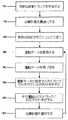
図10は、放射線療法治療の適用に含めることができるプロセスの流れ図を示す。このプロセスは計画の作成から始まる(ブロック300)。前述のとおり、計画および位相は、数学モデル、変形モデルおよび生理学的モデルを使用して決定することができる。複数の計画(ブロック304)が作成された後、それらを、放射線療法装置18へロードすることができる(ブロック308)。より具体的には、放射線療法装置18の構成要素および動作を(例えば受渡しモジュール97を介して)制御する能力を有するコンピュータ62へ、それらの計画をロードすることができる。 FIG. 10 shows a flow diagram of a process that can be included in the application of radiation therapy treatment. The process begins with the creation of a plan (block 300). As described above, the plan and phase can be determined using mathematical models, deformation models and physiological models. After multiple plans (block 304) have been created, they can be loaded into the radiation therapy device 18 (block 308). More specifically, those plans can be loaded into a
治療計画が放射線療法装置18(またはコンピュータ62)に記憶された後、患者14の放射線療法治療を始めることができる。治療の最初の段階では、運動パターンが監視され、評価される(ブロック312)。前述のとおり、運動パターンは、例えば運動検出装置89および取得モジュール94を使用して測定することができる。運動パターンを監視した後、その運動パターンに基づいて、潜在的な治療計画のリストを作成することができる(ブロック316)。治療計画は、計画と患者14の運動パターンとの間の時間関係および空間関係に従って評価することができる。潜在的な治療計画のリストが決定された後、治療計画または治療計画の組合せを選択することができる(ブロック320)。治療計画は、コンピュータ62に従って自動的に、または医師または他の専門家によって手動で選択することができる。一般に、関心領域の運動に最もよく一致した計画または計画の組合せが選択される。治療計画を選択した後、それを評価することができる(ブロック324)。評価パラメータには、関心領域の位置、関心領域の変形、投与されている線量、またはこれらの組合せに関する情報などが含まれる。いくつかの実装では、ブロック320で選択された計画が(例えば品質保証モジュール146によって)評価され、それが有効な治療であるとみなされない場合には、引渡す潜在的な治療計画を再評価するため、このプロセスはブロック316に戻ることができる。 After the treatment plan is stored in the radiation therapy device 18 (or computer 62), radiation therapy treatment of the patient 14 can begin. In the first stage of treatment, motion patterns are monitored and evaluated (block 312). As described above, the motion pattern can be measured using, for example, the motion detection device 89 and the
しかし、治療計画が評価され、それが、意図された結果を有すると見込まれた場合、その治療計画を、放射線療法装置18によって引渡すことができる(ブロック328)。計画の引渡し中に、このプロセスは戻ることができ、それ以降のステップを繰り返すことができる。他の実施態様では、計画が引渡しされた後、その計画が検証される(ブロック332)。引渡しの検証を使用して、患者14に実際に引渡しされた放射線の線量および起こった変形を決定することができる。前述のとおり、線量および変形の情報は、その後にどの計画を実施するのかに影響を及ぼすことができる。計画の引渡しが検証された後、このプロセスは、ブロック300の計画作成ステージに戻ることができ、プロセスを繰り返すことができる。他の実施態様では、プロセスが運動評価ブロック312に戻され、プロセスの残りステップが繰り返される。 However, if the treatment plan is evaluated and expected to have the intended result, the treatment plan can be delivered by the radiation therapy device 18 (block 328). During the delivery of the plan, the process can return and subsequent steps can be repeated. In other embodiments, after the plan is delivered, the plan is verified (block 332). Delivery verification can be used to determine the dose of radiation actually delivered to the
1.詳細な例:ターゲットを移動するためのらせん形共面IMRTビームの放出
前述のとおり、本発明を組み込むことができる放射線療法治療システムの例は、TomoTherapy,Inc.社(ウェブサイトはwww.tomotherapy.com)によって提供されているHI−ARTブランドの放射線療法システムである。TOMOTHERAPY HI−ARTブランドのシステムは、多くの態様で従来のIMRTに優るらせん形放射線療法治療システムの一例である。らせん形共面強度変調ビームの放出は利点の一例である。一実装では、このらせん形放出システムが一般に、以下の特徴を有する:1.固定されたジョー幅、2.固定されたジョー位置および向き、3.一定の治療台速度、4.一定のガントリ回転速度、ならびに5)強度変調のための1次元(1D)バイナリMLC。1. Detailed Example: Emission of a Helical Coplanar IMRT Beam to Move a Target As noted above, examples of radiation therapy treatment systems that can incorporate the present invention are described in TomoTherapy, Inc. (HI-ART brand radiation therapy system provided by the company (website: www.tomotherapy.com)). The TOMOTHERAPY HI-ART brand system is an example of a helical radiation therapy treatment system that in many ways is superior to the conventional IMRT. The emission of a helical coplanar intensity modulated beam is an example of an advantage. In one implementation, this helical delivery system generally has the following characteristics: 1. fixed jaw width; 2. fixed jaw position and orientation; 3. constant treatment table speed; Constant gantry rotation speed, as well as 5) one-dimensional (1D) binary MLC for intensity modulation.
しかし、一方で、この放出システムのこのような単純さは、移動する関心領域の状況(例えばターゲット運動は呼吸運動に起因する)においていくつかの限界も提示する。移動する関心領域の従来のゲーティングおよび追跡技法は、らせん形システムにおいて容易に実現することができない。例えば、ゲーティング技法は、ガントリの回転または治療台の運動を止めることを要求する。追跡技法は、リアルタイムジョー傾斜を要求する。患者が常に計画呼吸パターンに従う場合、BSDは魅力的である。しかし、らせん形システムが、位相外れの呼吸を補正することは難しい。 However, on the other hand, this simplicity of the release system also presents some limitations in the situation of the moving region of interest (eg the target motion is due to respiratory motion). Conventional gating and tracking techniques for moving regions of interest cannot be easily implemented in helical systems. For example, gating techniques require stopping gantry rotation or treatment table motion. The tracking technique requires real-time jaw tilt. BSD is attractive when a patient always follows a planned breathing pattern. However, it is difficult for a helical system to correct out-of-phase breathing.
修正らせん形システムの一構成に関して、このシステムは以下のことを仮定する:1.ターゲットの位置をリアルタイムで決定することができる;2.ターゲットの運動は剛体運動であり、変形は、たとえあったとしても、剛体運動に比べて無視することができる;3.1つの投射内のターゲット運動は無視することができる。仮定1は、治療前の患者の体の(4D CTなどの)4D表現と、(先に提示されたカメラ、肺活量計または治療ビームなどを使用した)リアルタイム位相決定技法との組合せによって実行可能である。仮定2は、大部分のケースに対して合理的である。これは、従来のIMRTで使用される追跡技法の基本的な仮定でもある。仮定3は実際に、TomoTherapy,Inc.社によって提供されるHI−ARTシステムなどのいくつかの引渡しシステムの時間分解能である。 For one configuration of a modified helical system, the system assumes the following: 1. Target location can be determined in real time; The target motion is a rigid motion and the deformation, if any, can be ignored compared to the rigid motion; 3. Target motion within one projection can be ignored.
いくつかの構成では、らせん形放出が投射状である。それぞれの投射は3つのパラメータによって指示される。
kは、回転インデックス(kは整数)、
φは、ガントリエンジェル(φ∈[0,2π])、
pは、MLCリーフインデックス p∈[−P/2,P/2]である。
対(k,φ)は投射インデックスからなる。時間tは、投射インデックスと線形比例する(t=t(k,φ))。In some configurations, the helical emission is projective. Each projection is indicated by three parameters.
k is the rotation index (k is an integer),
φ is the gantry angel (φ∈ [0,2π]),
p is the MLC leaf index pε [−P / 2, P / 2].
The pair (k, φ) consists of a projection index. The time t is linearly proportional to the projection index (t = t (k, φ)).
1回転あたりの治療台の進行をΔZとする。このとき、治療台位置は
[e2] ΔZ(k,φ)=(k+φ/(2π))ΔZ
である。Let the progression of the treatment table per rotation be ΔZ. At this time, the treatment table position is [e2] ΔZ (k, φ) = (k + φ / (2π)) ΔZ
It is.
計画作成サイノグラムをI=I(k,φ,p)とする。関数値I(k,φ,p)は、投射(k,φ)におけるリーフpに対するビームオン時間を表す。計画作成自体は、静的患者モデル(3D計画)またはBSDモデル(4D計画)に基づくことができる。 Let the planning sinogram be I = I (k, φ, p). The function value I (k, φ, p) represents the beam on time for the leaf p in the projection (k, φ). The planning itself can be based on a static patient model (3D plan) or a BSD model (4D plan).
引渡しサイノグラムをI’=I’(k,φ,p)とする。このサブセクションの1つの目的は、移動するターゲットの場合のI’=I’(k,φ,p)を決定することにある。
x=x(k,φ):投射(k,φ)における計画作成ターゲット位置。計画作成自体は、静的患者モデル(3D計画作成)またはBSDモデル(4D計画作成)に基づくことができる。x=(x,y,z)。Let the delivery sinogram be I ′ = I ′ (k, φ, p). One purpose of this subsection is to determine I ′ = I ′ (k, φ, p) for a moving target.
x = x (k, φ): Planned target position in projection (k, φ). The planning itself can be based on a static patient model (3D planning) or a BSD model (4D planning). x = (x, y, z).
x’=x’(k,φ):投射(k,φ)における放出ターゲット位置。これは、仮定1に従って決定される。
u=u(k,φ)=x’(k,φ)−x(k,φ):引渡しと計画作成の間のターゲットの変位。u=(ux,uy,uz)。x ′ = x ′ (k, φ): emission target position in projection (k, φ). This is determined according to
u = u (k, φ) = x ′ (k, φ) −x (k, φ): displacement of the target during delivery and planning. u = (ux , uy , uz ).
さらに、横ターゲット変位を、ビームに垂直な方向の(MLC線に平行な)成分u⊥と、ビームに平行な方向の成分u//とに分解することができる。結果は以下のとおりである。Furthermore, the horizontal target displacements, (parallel to MLC line) direction perpendicular to the beam and component u⊥, can be decomposed into the direction of the component u// parallel to the beam. The results are as follows.
[e3]u⊥(k,φ)=ux(k,φ)cosφ+uy(k,φ)sinφ
[e4]u//(k,φ)=ux(k,φ)sinφ+uy(k,φ)cosφ
ビームに平行な方向の運動成分u//に関しては、逆自乗補正および減衰補正が必要である。補正係数をrとする。[E3] u⊥ (k, φ) = ux (k, φ) cos φ + uy (k, φ) sin φ
[E4] u// (k, φ) = ux (k, φ) sin φ + uy (k, φ) cos φ
For the motion component u/// in the direction parallel to the beam, inverse square correction and attenuation correction are required. Let r be the correction coefficient.
[e5]r(k,φ)=r1(k,φ)r2(k,φ)
上式で、r1(k,φ)は逆自乗補正である。計画作成源−ターゲット距離をs(k,φ)とすると以下のとおり。[E5] r (k, φ) = r1 (k, φ) r2 (k, φ)
In the above equation, r1 (k, φ) is an inverse square correction. Assuming that the planning source-target distance is s (k, φ),
減衰補正をr2(k,φ)とすると以下のとおり。Assuming that the attenuation correction is r2 (k, φ), it is as follows.
式[e7]は、システムが4D CTを有する場合に限って実行可能であり、そうでなければ、システムは、他のいくつかの近似値を使用しなければならない。
ビームに垂直な方向の平面内運動成分u⊥は、MLCパターンをシフトすることによって補正可能である。すなわち以下のとおりである。Equation [e7] is feasible only if the system has 4D CT, otherwise the system must use some other approximation.
The in-plane motion component uの in the direction perpendicular to the beam can be corrected by shifting the MLC pattern. That is, it is as follows.
[e8]p’(k,φ)=p(k,φ)+u⊥(k,φ)
z成分の運動を補正するためには、投射をシフトする必要がある。さらに、RARが計画された最適の間隔を有するよう、計画作成サイノグラムと同じガントリ角度を保たなければならない。したがって、回転インデックスkを変更するだけでよい。[E8] p ′ (k, φ) = p (k, φ) + u⊥ (k, φ)
In order to correct the motion of the z component, it is necessary to shift the projection. In addition, the same gantry angle as the planning sinogram must be maintained so that the RAR has the optimal planned spacing. Therefore, it is only necessary to change the rotation index k.
[e10]φ’=φ
随意運動パターンのため、いくつかの投射が同じ投射にマップし、いくつかの投射がまったくマップされないことも起こりうる。随意に移動するターゲット54に対する放出戦略が、以下の擬似コードによって示されたとおりになるように、それぞれの投射に対する達成可能な最大ビームオン時間を、Imaxとすることを考えなければならない。[E10] φ ′ = φ
Because of the voluntary movement pattern, it is possible that some projections map to the same projection and some projections are not mapped at all. It should be considered that the maximum achievable beam-on time for each projection is Imax so that the emission strategy for the arbitrarily moving
図11は、横運動補正の表現である。点線は、計画ターゲット位置およびビーム強度であり、実線は、放出ターゲット位置およびビーム強度である。
図12は、移動するターゲット54用の静的計画を放出すらせん形システムを示す図である。実線は、それぞれの投射に対する計画ターゲット位置である。点線は、放出中の実際のターゲット位置である。正方形は、削られた投射を指示し、三角形は、ガントリおよび治療台がその位置にあるときの実際のターゲットを指示する。円は、その瞬間にどの投射を放出する必要があるかを指示する。円は通常、2つの回転間に位置する。ビーム強度を決定するために、一般に補間法を使用する必要がある。FIG. 11 is a representation of lateral motion correction. The dotted line is the planned target position and beam intensity, and the solid line is the emission target position and beam intensity.
FIG. 12 is a diagram illustrating a helical system emitting a static plan for a moving
図13は、ある呼吸運動パターンが計画され(BSD計画、実線)、実際のターゲット位置(点線)がBSD計画とは異なることを除き、図12と同様である。正方形は、削られた投射を指示し、三角形は、ガントリおよび治療台がその位置にあるときの実際のターゲットを指示する。円は、その瞬間にどの投射を放出する必要があるかを指示する。円は通常、2つの回転間に位置する。ビーム強度を決定するために、補間法を使用する必要がある。 FIG. 13 is similar to FIG. 12 except that a respiratory motion pattern is planned (BSD plan, solid line) and the actual target position (dotted line) is different from the BSD plan. The square indicates the sharpened projection, and the triangle indicates the actual target when the gantry and treatment table are in place. The circle indicates which projection needs to be emitted at that moment. A circle is usually located between two rotations. In order to determine the beam intensity, it is necessary to use an interpolation method.
したがって、本発明は特に、移動する関心領域に放射線療法を施す新規の有用なシステムおよび方法を提供する。前記特許請求の範囲には、本発明の様々な特徴および利点が記載されている。 Thus, the present invention particularly provides a new and useful system and method for applying radiation therapy to a moving region of interest. The following claims describe various features and advantages of the invention.
Claims (19)
Translated fromJapanese前記コンピュータプロセッサによりアクセス可能なコンピュータ可読媒体に記憶され、呼吸サイクルの異なる位相を表す複数の患者画像を取得し、前記複数の患者画像の少なくともひとつに対して前記検出器からの複数の予想される応答を計算し、前記収集された透過放射線から前記患者の伝送データを取得し、前記伝送データを前記複数の予想される検出器の応答と比較するように動作可能なソフトウェアプログラムと、
を備える放射線療法を受けている患者の呼吸位相を検出するシステム。A radiation therapy device comprising a computer processor, a radiation module operable to emit radiation to a patient, and a detector operable to collect transmitted radiation;
A plurality of patient images stored in a computer readable medium accessibleby the computer processor and representingdifferent phases of a respiratory cycle, and a plurality of expected from the detector for at least one of the plurality of patient images; A software program operableto calculate a response, obtain the patient transmission data from the collected transmitted radiation, and compare the transmission data withthe response of the plurality of expected detectors ;
A system for detecting the respiratory phase of a patient undergoing radiation therapy.
Applications Claiming Priority (5)
| Application Number | Priority Date | Filing Date | Title |
|---|---|---|---|
| US70154105P | 2005-07-22 | 2005-07-22 | |
| US70158005P | 2005-07-22 | 2005-07-22 | |
| US60/701,541 | 2005-07-22 | ||
| US60/701,580 | 2005-07-22 | ||
| PCT/US2006/028351WO2007014026A2 (en) | 2005-07-22 | 2006-07-21 | System and method of detecting a breathing phase of a patient receiving radiation therapy |
Publications (3)
| Publication Number | Publication Date |
|---|---|
| JP2009502245A JP2009502245A (en) | 2009-01-29 |
| JP2009502245A5 JP2009502245A5 (en) | 2009-09-10 |
| JP5060476B2true JP5060476B2 (en) | 2012-10-31 |
Family
ID=37683822
Family Applications (1)
| Application Number | Title | Priority Date | Filing Date |
|---|---|---|---|
| JP2008522987AActiveJP5060476B2 (en) | 2005-07-22 | 2006-07-21 | System and method for detecting respiratory phase of a patient undergoing radiation therapy |
Country Status (10)
| Country | Link |
|---|---|
| US (1) | US8229068B2 (en) |
| EP (1) | EP1906826A4 (en) |
| JP (1) | JP5060476B2 (en) |
| KR (2) | KR20080039916A (en) |
| CN (1) | CN101267768A (en) |
| AT (1) | ATE507879T1 (en) |
| CA (1) | CA2616272A1 (en) |
| DE (1) | DE602006021803D1 (en) |
| TW (2) | TW200722134A (en) |
| WO (1) | WO2007014026A2 (en) |
Cited By (1)
| Publication number | Priority date | Publication date | Assignee | Title |
|---|---|---|---|---|
| JP2014104360A (en)* | 2012-11-27 | 2014-06-09 | Ge Medical Systems Global Technology Co Llc | Synchronous radiotherapy method and system |
Families Citing this family (132)
| Publication number | Priority date | Publication date | Assignee | Title |
|---|---|---|---|---|
| US7609512B2 (en) | 2001-11-19 | 2009-10-27 | Otter Products, Llc | Protective enclosure for electronic device |
| US7957507B2 (en) | 2005-02-28 | 2011-06-07 | Cadman Patrick F | Method and apparatus for modulating a radiation beam |
| US8232535B2 (en) | 2005-05-10 | 2012-07-31 | Tomotherapy Incorporated | System and method of treating a patient with radiation therapy |
| WO2007014105A2 (en) | 2005-07-22 | 2007-02-01 | Tomotherapy Incorporated | Method and system for adapting a radiation therapy treatment plan based on a biological model |
| JP5060476B2 (en)* | 2005-07-22 | 2012-10-31 | トモセラピー・インコーポレーテッド | System and method for detecting respiratory phase of a patient undergoing radiation therapy |
| KR20080044251A (en) | 2005-07-22 | 2008-05-20 | 토모테라피 인코포레이티드 | How to place a constraint on a deformation map and system implementing the method |
| AU2006272746A1 (en) | 2005-07-22 | 2007-02-01 | Tomotherapy Incorporated | Method and system for evaluating delivered dose |
| WO2007014104A2 (en) | 2005-07-22 | 2007-02-01 | Tomotherapy Incorporated | System and method of evaluating dose delivered by a radiation therapy system |
| KR20080049716A (en)* | 2005-07-22 | 2008-06-04 | 토모테라피 인코포레이티드 | Methods and systems for evaluating quality assurance criteria associated with delivery of treatment plans |
| JP2009502250A (en) | 2005-07-22 | 2009-01-29 | トモセラピー・インコーポレーテッド | Method and system for processing data associated with radiation therapy treatment planning |
| CA2616296A1 (en) | 2005-07-22 | 2007-02-01 | Tomotherapy Incorporated | System and method of generating contour structures using a dose volume histogram |
| US8442287B2 (en) | 2005-07-22 | 2013-05-14 | Tomotherapy Incorporated | Method and system for evaluating quality assurance criteria in delivery of a treatment plan |
| CN101512547A (en) | 2005-07-22 | 2009-08-19 | 断层放疗公司 | Method of and system for predicting dose delivery |
| CN101267857A (en) | 2005-07-22 | 2008-09-17 | 断层放疗公司 | System and method of delivering radiation therapy to a moving region of interest |
| US9731148B2 (en) | 2005-07-23 | 2017-08-15 | Tomotherapy Incorporated | Radiation therapy imaging and delivery utilizing coordinated motion of gantry and couch |
| ATE538841T1 (en) | 2005-10-17 | 2012-01-15 | Alberta Health Services | INTEGRATED EXTERNAL BEAM RADIOTHERAPY AND MRI SYSTEM |
| CA2626536C (en) | 2005-10-17 | 2016-04-26 | Alberta Cancer Board | Real-time dose reconstruction using dynamic simulation and image guided adaptive radiotherapy |
| US8600528B2 (en)* | 2006-09-18 | 2013-12-03 | The Research Foundation Of State University Of New York | Real-time, packet-level quality assurance of electromechanical device control data |
| US7609810B2 (en)* | 2006-12-14 | 2009-10-27 | Byong Yong Yi | Treatment-speed regulated tumor-tracking |
| US20090030307A1 (en)* | 2007-06-04 | 2009-01-29 | Assaf Govari | Intracorporeal location system with movement compensation |
| CN101820948A (en)* | 2007-10-25 | 2010-09-01 | 断层放疗公司 | System and method for motion adaptive optimization of radiotherapy delivery |
| US7699522B2 (en)* | 2007-10-29 | 2010-04-20 | Vladmir Varchena | Four-dimensional computed tomography quality assurance device |
| WO2009056151A1 (en)* | 2007-10-30 | 2009-05-07 | Elekta Ab (Publ) | Radiotherapy apparatus |
| EP2070478B1 (en)* | 2007-12-13 | 2011-11-23 | BrainLAB AG | Detection of the position of a moving object and treatment method |
| US7720196B2 (en)* | 2008-01-07 | 2010-05-18 | Accuray Incorporated | Target tracking using surface scanner and four-dimensional diagnostic imaging data |
| KR100981781B1 (en)* | 2008-02-29 | 2010-09-10 | 재단법인 한국원자력의학원 | Collimator device for radiation therapy and radiation therapy device using the device |
| US8519365B2 (en) | 2008-05-22 | 2013-08-27 | Vladimir Balakin | Charged particle cancer therapy imaging method and apparatus |
| US9177751B2 (en) | 2008-05-22 | 2015-11-03 | Vladimir Balakin | Carbon ion beam injector apparatus and method of use thereof |
| US8624528B2 (en) | 2008-05-22 | 2014-01-07 | Vladimir Balakin | Method and apparatus coordinating synchrotron acceleration periods with patient respiration periods |
| US8129699B2 (en) | 2008-05-22 | 2012-03-06 | Vladimir Balakin | Multi-field charged particle cancer therapy method and apparatus coordinated with patient respiration |
| US8178859B2 (en) | 2008-05-22 | 2012-05-15 | Vladimir Balakin | Proton beam positioning verification method and apparatus used in conjunction with a charged particle cancer therapy system |
| US8710462B2 (en) | 2008-05-22 | 2014-04-29 | Vladimir Balakin | Charged particle cancer therapy beam path control method and apparatus |
| JP2011523169A (en) | 2008-05-22 | 2011-08-04 | エゴロヴィチ バラキン、ウラジミール | Charged particle beam extraction method and apparatus for use with a charged particle cancer treatment system |
| US9155911B1 (en) | 2008-05-22 | 2015-10-13 | Vladimir Balakin | Ion source method and apparatus used in conjunction with a charged particle cancer therapy system |
| US8975600B2 (en) | 2008-05-22 | 2015-03-10 | Vladimir Balakin | Treatment delivery control system and method of operation thereof |
| US9616252B2 (en) | 2008-05-22 | 2017-04-11 | Vladimir Balakin | Multi-field cancer therapy apparatus and method of use thereof |
| US9910166B2 (en) | 2008-05-22 | 2018-03-06 | Stephen L. Spotts | Redundant charged particle state determination apparatus and method of use thereof |
| US9095040B2 (en) | 2008-05-22 | 2015-07-28 | Vladimir Balakin | Charged particle beam acceleration and extraction method and apparatus used in conjunction with a charged particle cancer therapy system |
| US8718231B2 (en) | 2008-05-22 | 2014-05-06 | Vladimir Balakin | X-ray tomography method and apparatus used in conjunction with a charged particle cancer therapy system |
| US9855444B2 (en) | 2008-05-22 | 2018-01-02 | Scott Penfold | X-ray detector for proton transit detection apparatus and method of use thereof |
| US9682254B2 (en) | 2008-05-22 | 2017-06-20 | Vladimir Balakin | Cancer surface searing apparatus and method of use thereof |
| US8569717B2 (en) | 2008-05-22 | 2013-10-29 | Vladimir Balakin | Intensity modulated three-dimensional radiation scanning method and apparatus |
| US8188688B2 (en) | 2008-05-22 | 2012-05-29 | Vladimir Balakin | Magnetic field control method and apparatus used in conjunction with a charged particle cancer therapy system |
| US8642978B2 (en) | 2008-05-22 | 2014-02-04 | Vladimir Balakin | Charged particle cancer therapy dose distribution method and apparatus |
| US8598543B2 (en) | 2008-05-22 | 2013-12-03 | Vladimir Balakin | Multi-axis/multi-field charged particle cancer therapy method and apparatus |
| US10092776B2 (en) | 2008-05-22 | 2018-10-09 | Susan L. Michaud | Integrated translation/rotation charged particle imaging/treatment apparatus and method of use thereof |
| EP2283711B1 (en) | 2008-05-22 | 2018-07-11 | Vladimir Yegorovich Balakin | Charged particle beam acceleration apparatus as part of a charged particle cancer therapy system |
| US9937362B2 (en) | 2008-05-22 | 2018-04-10 | W. Davis Lee | Dynamic energy control of a charged particle imaging/treatment apparatus and method of use thereof |
| US8896239B2 (en) | 2008-05-22 | 2014-11-25 | Vladimir Yegorovich Balakin | Charged particle beam injection method and apparatus used in conjunction with a charged particle cancer therapy system |
| US8089054B2 (en) | 2008-05-22 | 2012-01-03 | Vladimir Balakin | Charged particle beam acceleration and extraction method and apparatus used in conjunction with a charged particle cancer therapy system |
| US8969834B2 (en) | 2008-05-22 | 2015-03-03 | Vladimir Balakin | Charged particle therapy patient constraint apparatus and method of use thereof |
| US10143854B2 (en) | 2008-05-22 | 2018-12-04 | Susan L. Michaud | Dual rotation charged particle imaging / treatment apparatus and method of use thereof |
| US7939809B2 (en) | 2008-05-22 | 2011-05-10 | Vladimir Balakin | Charged particle beam extraction method and apparatus used in conjunction with a charged particle cancer therapy system |
| US9981147B2 (en) | 2008-05-22 | 2018-05-29 | W. Davis Lee | Ion beam extraction apparatus and method of use thereof |
| US8907309B2 (en) | 2009-04-17 | 2014-12-09 | Stephen L. Spotts | Treatment delivery control system and method of operation thereof |
| US9737272B2 (en) | 2008-05-22 | 2017-08-22 | W. Davis Lee | Charged particle cancer therapy beam state determination apparatus and method of use thereof |
| US9782140B2 (en) | 2008-05-22 | 2017-10-10 | Susan L. Michaud | Hybrid charged particle / X-ray-imaging / treatment apparatus and method of use thereof |
| CA2725493C (en) | 2008-05-22 | 2015-08-18 | Vladimir Yegorovich Balakin | Charged particle cancer therapy beam path control method and apparatus |
| US9744380B2 (en) | 2008-05-22 | 2017-08-29 | Susan L. Michaud | Patient specific beam control assembly of a cancer therapy apparatus and method of use thereof |
| WO2009142549A2 (en) | 2008-05-22 | 2009-11-26 | Vladimir Yegorovich Balakin | Multi-axis charged particle cancer therapy method and apparatus |
| US8637833B2 (en) | 2008-05-22 | 2014-01-28 | Vladimir Balakin | Synchrotron power supply apparatus and method of use thereof |
| US9498649B2 (en) | 2008-05-22 | 2016-11-22 | Vladimir Balakin | Charged particle cancer therapy patient constraint apparatus and method of use thereof |
| US10029122B2 (en) | 2008-05-22 | 2018-07-24 | Susan L. Michaud | Charged particle—patient motion control system apparatus and method of use thereof |
| US9056199B2 (en) | 2008-05-22 | 2015-06-16 | Vladimir Balakin | Charged particle treatment, rapid patient positioning apparatus and method of use thereof |
| US9974978B2 (en) | 2008-05-22 | 2018-05-22 | W. Davis Lee | Scintillation array apparatus and method of use thereof |
| US8368038B2 (en) | 2008-05-22 | 2013-02-05 | Vladimir Balakin | Method and apparatus for intensity control of a charged particle beam extracted from a synchrotron |
| US8627822B2 (en) | 2008-07-14 | 2014-01-14 | Vladimir Balakin | Semi-vertical positioning method and apparatus used in conjunction with a charged particle cancer therapy system |
| US9262590B2 (en) | 2008-08-14 | 2016-02-16 | Koninklijke Philips N.V. | Prospective adaptive radiation therapy planning |
| US7796731B2 (en)* | 2008-08-22 | 2010-09-14 | Varian Medical Systems International Ag | Leaf sequencing algorithm for moving targets |
| WO2010052596A1 (en)* | 2008-11-04 | 2010-05-14 | Koninklijke Philips Electronics, N.V. | Method and system for ultrasound therapy |
| WO2010058863A1 (en)* | 2008-11-21 | 2010-05-27 | 国立大学法人東北大学 | Signal processing device, signal processing method, signal processing program, computer-readable recording medium on which is recorded a signal processing program, and radiation therapy device |
| BRPI0924903B8 (en)* | 2009-03-04 | 2021-06-22 | Zakrytoe Aktsionernoe Obshchestvo Protom | apparatus for generating a negative ion beam for use in charged particle radiation therapy and method for generating a negative ion beam for use with charged particle radiation therapy |
| US20120002780A1 (en)* | 2009-03-25 | 2012-01-05 | Koninklijke Philips Electronics N.V. | Method and apparatus for breathing adapted imaging |
| US20110019889A1 (en)* | 2009-06-17 | 2011-01-27 | David Thomas Gering | System and method of applying anatomically-constrained deformation |
| US8331532B2 (en)* | 2010-02-18 | 2012-12-11 | Varian Medical Systems International Ag | Method and system for treating moving target |
| EP2921205B1 (en) | 2010-03-26 | 2016-07-27 | Brainlab AG | Controlling a process of monitoring the position of a patient during a radiation treatment |
| US10179250B2 (en) | 2010-04-16 | 2019-01-15 | Nick Ruebel | Auto-updated and implemented radiation treatment plan apparatus and method of use thereof |
| US9737731B2 (en) | 2010-04-16 | 2017-08-22 | Vladimir Balakin | Synchrotron energy control apparatus and method of use thereof |
| US10086214B2 (en) | 2010-04-16 | 2018-10-02 | Vladimir Balakin | Integrated tomography—cancer treatment apparatus and method of use thereof |
| US10188877B2 (en) | 2010-04-16 | 2019-01-29 | W. Davis Lee | Fiducial marker/cancer imaging and treatment apparatus and method of use thereof |
| US8542797B2 (en)* | 2010-09-24 | 2013-09-24 | Elekta Ab (Publ) | Radiotherapy apparatus configured to track a motion of a target region using a combination of a multileaf collimator and a patient support |
| US8824630B2 (en)* | 2010-10-29 | 2014-09-02 | Accuray Incorporated | Method and apparatus for treating a target's partial motion range |
| CN102985137B (en) | 2010-11-16 | 2015-10-21 | 三菱电机株式会社 | Breathe guiding device, breathe boot and particle-beam therapeutic apparatus |
| US8503753B2 (en)* | 2010-12-02 | 2013-08-06 | Kabushiki Kaisha Toshiba | System and method for triangular interpolation in image reconstruction for PET |
| EP2653191B1 (en)* | 2011-02-17 | 2015-08-19 | Mitsubishi Electric Corporation | Particle beam therapy system |
| US8963112B1 (en) | 2011-05-25 | 2015-02-24 | Vladimir Balakin | Charged particle cancer therapy patient positioning method and apparatus |
| CN102847237B (en)* | 2011-06-28 | 2016-05-18 | 苏州雷泰医疗科技有限公司 | A kind of head stereotactic radiotherapeutic device |
| US8619945B2 (en)* | 2011-09-20 | 2013-12-31 | Siemens Medical Solutions Usa, Inc. | Prediction-based breathing control apparatus for radiation therapy |
| JP6140197B2 (en)* | 2012-03-08 | 2017-05-31 | ザ・ジョンズ・ホプキンス・ユニバーシティ | Method and apparatus for measuring quality accuracy of machine and dosimetry in radiotherapy in real time |
| KR101463681B1 (en)* | 2012-03-09 | 2014-11-20 | 성균관대학교산학협력단 | System for inducing respiration using biofeedback principle |
| KR101307673B1 (en)* | 2012-06-27 | 2013-09-26 | 주식회사 나노포커스레이 | Images obtaining method synchronized with respiration for computed tomography scanner |
| EP2962309B1 (en) | 2013-02-26 | 2022-02-16 | Accuray, Inc. | Electromagnetically actuated multi-leaf collimator |
| US9627098B2 (en)* | 2013-03-14 | 2017-04-18 | Varex Imaging Corporation | Real-time moving collimators made with X-ray filtering material |
| KR101464330B1 (en)* | 2013-04-26 | 2014-11-24 | 서울대학교병원 | Method of comparing preoperative respiratory level with intraoperative respiratory level |
| WO2014175608A1 (en)* | 2013-04-26 | 2014-10-30 | 재단법인 아산사회복지재단 | Method for comparing preoperative respiratory level with intraoperative respiratory level |
| JP6144114B2 (en)* | 2013-05-22 | 2017-06-07 | 住友重機械工業株式会社 | Neutron capture therapy device and irradiation object position correction method |
| CN105451817B (en)* | 2013-08-06 | 2019-01-11 | 皇家飞利浦有限公司 | Method and system for the effectiveness that automatic estimation self-adaptive radiation therapy is planned again |
| CN106170317B (en)* | 2013-08-07 | 2019-03-29 | 皇家飞利浦有限公司 | Treatment planning |
| KR101623834B1 (en)* | 2013-08-09 | 2016-05-24 | 삼성전자주식회사 | Apparatus and method for providing contents related to taking a medical image |
| WO2015038832A1 (en)* | 2013-09-11 | 2015-03-19 | The Board Of Trustees Of The Leland Stanford Junior University | Arrays of accelerating structures and rapid imaging for facilitating rapid radiation therapies |
| US9265971B2 (en)* | 2014-02-07 | 2016-02-23 | Varian Medical Systems, Inc. | Systems, methods, and devices for real-time treatment verification using an electronic portal imaging device |
| US9492685B2 (en) | 2014-06-13 | 2016-11-15 | Infinitt Healthcare Co., Ltd. | Method and apparatus for controlling and monitoring position of radiation treatment system |
| KR101617773B1 (en) | 2014-06-19 | 2016-05-03 | 주식회사 인피니트헬스케어 | Method and apparatus for monitoring position of radiation treatment system |
| US9472082B2 (en)* | 2014-06-23 | 2016-10-18 | Bruno Delean | Vision based system for detecting distress behavior |
| JP6334349B2 (en)* | 2014-09-19 | 2018-05-30 | 株式会社東芝 | Particle beam therapy system, particle beam therapy device operating method, and particle beam therapy program |
| DE102015200353B4 (en)* | 2015-01-13 | 2017-11-16 | Siemens Healthcare Gmbh | Method for recording a magnetic resonance image data set and magnetic resonance device |
| DE102016200433B4 (en)* | 2016-01-15 | 2024-05-23 | Siemens Healthineers Ag | Procedure for planning radiation treatment of a patient and radiation treatment planning unit |
| US9907981B2 (en) | 2016-03-07 | 2018-03-06 | Susan L. Michaud | Charged particle translation slide control apparatus and method of use thereof |
| KR102063271B1 (en)* | 2016-03-17 | 2020-01-07 | 사회복지법인 삼성생명공익재단 | Ultrasound treatment apparatus and driving method thereof |
| JP6925364B2 (en)* | 2016-03-30 | 2021-08-25 | コーニンクレッカ フィリップス エヌ ヴェKoninklijke Philips N.V. | Adaptive radiation therapy plan |
| KR101817423B1 (en)* | 2016-04-29 | 2018-01-10 | 주식회사 한빔테크놀로지 | Respiratory gating system |
| US9981144B2 (en)* | 2016-09-30 | 2018-05-29 | Varian Medical Systems Particle Therapy Gmbh | System and method for scanned ion beam interplay effect mitigation using random repainting |
| US11446520B2 (en)* | 2017-03-14 | 2022-09-20 | National Univ. Corporation Hokkaido Univ. | Radiation therapy apparatus configured to track a tracking object moving in an irradiation object |
| KR102024427B1 (en) | 2017-06-05 | 2019-09-23 | 경희대학교 산학협력단 | Training System for spontaneous breathing using MEMS sensor |
| GB2563256A (en)* | 2017-06-07 | 2018-12-12 | Vision Rt Ltd | Patient monitoring system |
| CN110678224B (en)* | 2017-06-19 | 2022-05-13 | 深圳市奥沃医学新技术发展有限公司 | Device for tracking and irradiating target spot by using radiotherapy equipment and radiotherapy equipment |
| US10426424B2 (en) | 2017-11-21 | 2019-10-01 | General Electric Company | System and method for generating and performing imaging protocol simulations |
| KR102457972B1 (en)* | 2018-04-24 | 2022-10-24 | 사회복지법인 삼성생명공익재단 | The apparatus for generating respiratory signals, the system and operating method for respiratory gated radiotherapy |
| CN108744313A (en)* | 2018-06-25 | 2018-11-06 | 西安大医数码科技有限公司 | Radiotherapy planning planing method, radiotherapy planning system and radiotherapy system |
| US20210121150A1 (en)* | 2018-07-09 | 2021-04-29 | William Beaumont Hospital | On-board charged particle therapy computed tomography system |
| US11083913B2 (en)* | 2018-10-25 | 2021-08-10 | Elekta, Inc. | Machine learning approach to real-time patient motion monitoring |
| DE102018008806A1 (en)* | 2018-11-09 | 2020-05-14 | Städtisches Klinikum Dessau | Procedure for the authenticity-related correction of the spatial position of the central beam of radiation therapy devices and the patient position |
| US12239852B2 (en)* | 2018-11-28 | 2025-03-04 | Steven Thomas, et al. | Motion synchronized arc radiotherapy |
| US20220212037A1 (en)* | 2019-04-22 | 2022-07-07 | Suzhou Linatech Medical Science and Technology Co.,Ltd. | Radiotherapy device and radiotherapy method |
| CN113727650B (en)* | 2019-04-26 | 2025-04-25 | 医科达有限公司 | Method for delivering proton radiation therapy using periodic motion |
| CN117083107A (en)* | 2021-01-26 | 2023-11-17 | 阿朵思有限责任公司 | System and method for dose guidance and repeated estimation of final delivered radiation dose for a radiation therapy system |
| WO2022170607A1 (en)* | 2021-02-10 | 2022-08-18 | 北京大学 | Positioning image conversion system |
| KR102568269B1 (en)* | 2021-06-09 | 2023-08-18 | 서울대학교산학협력단 | System for monitoring patient motion in radiation therapy based on inertial measurement unit sensor |
| US11992705B2 (en)* | 2021-09-29 | 2024-05-28 | Siemens Healthineers International Ag | On-line adaptive deep inspiration breath-hold treatment |
| CN114225236B (en)* | 2021-12-20 | 2025-02-25 | 联影(常州)医疗科技有限公司 | Radiotherapy guidance device, method, electronic device and storage medium |
| US11712584B1 (en)* | 2022-05-24 | 2023-08-01 | Accuray Incorporated | Prospective and retrospective on-line adaptive radiotherapy |
| CN115154924A (en)* | 2022-05-31 | 2022-10-11 | 深圳市奥沃医学新技术发展有限公司 | Radiation delivery control method, computer equipment and storage medium |
Family Cites Families (372)
| Publication number | Priority date | Publication date | Assignee | Title |
|---|---|---|---|---|
| US692203A (en)* | 1901-02-15 | 1902-01-28 | George E Le Clair | Machine for making wood fiber. |
| DE2302938C3 (en) | 1973-01-22 | 1979-07-12 | Polymer-Physik Gmbh & Co Kg, 2844 Lemfoerde | Multi-stage accelerator for charged particles with high vacuum insulation |
| US4189470A (en) | 1973-01-30 | 1980-02-19 | Bio-Response, Inc. | Method for the continuous removal of a specific antibody from the lymph fluid in animals and humans |
| US3964467A (en) | 1973-01-30 | 1976-06-22 | Bio Response Inc. | Methods and apparatus for augmentation of the production of anti-bodies in animals and humans and the collection thereof |
| CA990404A (en) | 1974-08-01 | 1976-06-01 | Stanley O. Schriber | Double pass linear accelerator operating in a standing wave mode |
| GB1503517A (en) | 1974-09-10 | 1978-03-15 | Science Res Council | Electrostatic accelerators |
| US4208185A (en) | 1976-08-16 | 1980-06-17 | Mitsubishi Chemical Industries Limited | Method and apparatus for the measurement of antigens and antibodies |
| US4149081A (en) | 1976-11-29 | 1979-04-10 | Varian Associates, Inc. | Removal of spectral artifacts and utilization of spectral effects in computerized tomography |
| FR2390069B1 (en) | 1977-05-05 | 1981-04-30 | Commissariat Energie Atomique | |
| DE2804393C2 (en) | 1978-02-02 | 1987-01-02 | Jens Prof. Dr. 8520 Buckenhof Christiansen | Method for generating and accelerating electrons or ions in a discharge vessel, as well as associated particle accelerator and further associated applications of the method |
| US4273867A (en) | 1979-04-05 | 1981-06-16 | Mallinckrodt, Inc. | Method and reagent for counteracting lipemic interference |
| US4314180A (en) | 1979-10-16 | 1982-02-02 | Occidental Research Corporation | High density ion source |
| US4395631A (en) | 1979-10-16 | 1983-07-26 | Occidental Research Corporation | High density ion source |
| US4426582A (en) | 1980-01-21 | 1984-01-17 | Oregon Graduate Center | Charged particle beam apparatus and method utilizing liquid metal field ionization source and asymmetric three element lens system |
| JPS5752967A (en) | 1980-09-17 | 1982-03-29 | Nec Corp | Device for immediately calculating and displaying dose distribution |
| US4393334A (en) | 1981-02-09 | 1983-07-12 | David Glaser | Electron acceleration in ionizable gas |
| US4388560A (en) | 1981-05-26 | 1983-06-14 | Hughes Aircraft Company | Filament dispenser cathode |
| US4401765A (en) | 1981-09-01 | 1983-08-30 | E. I. Du Pont De Nemours And Company | Covalently bonded high refractive index particle reagents and their use in light scattering immunoassays |
| US4480042A (en) | 1981-10-28 | 1984-10-30 | E. I. Du Pont De Nemours And Company | Covalently bonded high refractive index particle reagents and their use in light scattering immunoassays |
| US4446403A (en) | 1982-05-26 | 1984-05-01 | International Business Machines Corporation | Compact plug connectable ion source |
| US4570103A (en) | 1982-09-30 | 1986-02-11 | Schoen Neil C | Particle beam accelerators |
| NL8400845A (en) | 1984-03-16 | 1985-10-16 | Optische Ind De Oude Delft Nv | DEVICE FOR GAP RADIOGRAPHY. |
| US4703018A (en) | 1985-02-20 | 1987-10-27 | E. I. Du Pont De Nemours And Company | High refractive index haloalkyl-functional shell-core polymers and their use in light scattering immunoassays |
| US4752692A (en) | 1985-04-26 | 1988-06-21 | Hughes Aircraft Company | Liquid metal ion source |
| US4815446A (en) | 1985-05-09 | 1989-03-28 | Alpha Therapeutic Corporation | Process for treating metastasis of cancerous tumors |
| US4664869A (en) | 1985-07-01 | 1987-05-12 | The United States Of America As Represented By The United States Department Of Energy | Method for the simultaneous preparation of Radon-211, Xenon-125, Xenon-123, Astatine-211, Iodine-125 and Iodine-123 |
| US4868843A (en) | 1986-09-10 | 1989-09-19 | Varian Associates, Inc. | Multileaf collimator and compensator for radiotherapy machines |
| US4736106A (en) | 1986-10-08 | 1988-04-05 | Michigan State University | Method and apparatus for uniform charged particle irradiation of a surface |
| JPS63122923A (en) | 1986-11-13 | 1988-05-26 | Agency Of Ind Science & Technol | Ultrasonic thermometric apparatus |
| US4912731A (en) | 1987-04-13 | 1990-03-27 | Vittorio Nardi | Plasma focus apparatus with field distortion elements |
| US4818914A (en) | 1987-07-17 | 1989-04-04 | Sri International | High efficiency lamp |
| US4879518A (en) | 1987-10-13 | 1989-11-07 | Sysmed, Inc. | Linear particle accelerator with seal structure between electrodes and insulators |
| US4870287A (en) | 1988-03-03 | 1989-09-26 | Loma Linda University Medical Center | Multi-station proton beam therapy system |
| US5073913A (en) | 1988-04-26 | 1991-12-17 | Acctek Associates, Inc. | Apparatus for acceleration and application of negative ions and electrons |
| JPH01299537A (en) | 1988-05-27 | 1989-12-04 | Agency Of Ind Science & Technol | Acoustic characteristic and temperature measuring method and its device |
| US5250388A (en) | 1988-05-31 | 1993-10-05 | Westinghouse Electric Corp. | Production of highly conductive polymers for electronic circuits |
| US5124658A (en) | 1988-06-13 | 1992-06-23 | Adler Richard J | Nested high voltage generator/particle accelerator |
| JPH078300B2 (en) | 1988-06-21 | 1995-02-01 | 三菱電機株式会社 | Charged particle beam irradiation device |
| EP0371303B1 (en) | 1988-11-29 | 1994-04-27 | Varian International AG. | Radiation therapy apparatus |
| US4998268A (en) | 1989-02-09 | 1991-03-05 | James Winter | Apparatus and method for therapeutically irradiating a chosen area using a diagnostic computer tomography scanner |
| US5117829A (en) | 1989-03-31 | 1992-06-02 | Loma Linda University Medical Center | Patient alignment system and procedure for radiation treatment |
| US5003998A (en) | 1989-04-21 | 1991-04-02 | Collett Donald H | Method and apparatus for cleaning and sanitizing HVAC systems |
| US5008907A (en) | 1989-05-31 | 1991-04-16 | The Regents Of The University Of California | Therapy x-ray scanner |
| EP0405282A1 (en) | 1989-06-30 | 1991-01-02 | Siemens Aktiengesellschaft | Apparatus for treatment of a living body with focused shockwaves |
| JP2515022B2 (en) | 1989-08-22 | 1996-07-10 | 株式会社東芝 | Accelerator controller |
| US5065315A (en) | 1989-10-24 | 1991-11-12 | Garcia Angela M | System and method for scheduling and reporting patient related services including prioritizing services |
| US5474911A (en) | 1989-12-01 | 1995-12-12 | The Board Of Trustees Of Leland Stanford Jr. University | Promotion of high specificity molecular assembly |
| ES2079467T3 (en) | 1989-12-19 | 1996-01-16 | Ciba Geigy Ag | PROCEDURE AND DEVICE FOR THE GENETIC TRANSFORMATION OF CELLS. |
| US5346548A (en) | 1990-06-25 | 1994-09-13 | The Regents Of The University Of California | Highly durable cement products containing siliceous ashes |
| EP0489904B1 (en) | 1990-07-02 | 1998-03-04 | Varian Associates, Inc. | Radiation therapy x-ray simulator |
| US5084682A (en) | 1990-09-07 | 1992-01-28 | Science Applications International Corporation | Close-coupled RF power systems for linacs |
| US6405072B1 (en) | 1991-01-28 | 2002-06-11 | Sherwood Services Ag | Apparatus and method for determining a location of an anatomical target with reference to a medical apparatus |
| US5210414A (en) | 1991-03-29 | 1993-05-11 | The United States Of America As Represented By The Department Of Health And Human Services | Differential surface composition analysis by multiple-voltage electron beam X-ray spectroscopy |
| US5596653A (en) | 1991-04-09 | 1997-01-21 | Mitsubishi Denki Kabushiki Kaisha | Radiation therapy treatment planning system |
| US5317616A (en) | 1992-03-19 | 1994-05-31 | Wisconsin Alumni Research Foundation | Method and apparatus for radiation therapy |
| US5661773A (en) | 1992-03-19 | 1997-08-26 | Wisconsin Alumni Research Foundation | Interface for radiation therapy machine |
| US5351280A (en) | 1992-03-19 | 1994-09-27 | Wisconsin Alumni Research Foundation | Multi-leaf radiation attenuator for radiation therapy |
| US5335255A (en) | 1992-03-24 | 1994-08-02 | Seppi Edward J | X-ray scanner with a source emitting plurality of fan beams |
| US5332908A (en) | 1992-03-31 | 1994-07-26 | Siemens Medical Laboratories, Inc. | Method for dynamic beam profile generation |
| US5382914A (en) | 1992-05-05 | 1995-01-17 | Accsys Technology, Inc. | Proton-beam therapy linac |
| US5453310A (en) | 1992-08-11 | 1995-09-26 | E. Khashoggi Industries | Cementitious materials for use in packaging containers and their methods of manufacture |
| US5641584A (en) | 1992-08-11 | 1997-06-24 | E. Khashoggi Industries | Highly insulative cementitious matrices and methods for their manufacture |
| US5580624A (en) | 1992-08-11 | 1996-12-03 | E. Khashoggi Industries | Food and beverage containers made from inorganic aggregates and polysaccharide, protein, or synthetic organic binders, and the methods of manufacturing such containers |
| US5596619A (en) | 1992-08-21 | 1997-01-21 | Nomos Corporation | Method and apparatus for conformal radiation therapy |
| US5391139A (en) | 1992-09-03 | 1995-02-21 | William Beaumont Hospital | Real time radiation treatment planning system |
| KR940009563B1 (en) | 1992-09-04 | 1994-10-15 | 대우전자주식회사 | dish washer |
| US5405309A (en) | 1993-04-28 | 1995-04-11 | Theragenics Corporation | X-ray emitting interstitial implants |
| US5877192A (en) | 1993-05-28 | 1999-03-02 | Astra Aktiebolag | Method for the treatment of gastric acid-related diseases and production of medication using (-) enantiomer of omeprazole |
| EP0810005B1 (en) | 1993-06-09 | 2000-09-27 | Wisconsin Alumni Research Foundation | Radiation therapy system |
| DE69416587T2 (en) | 1993-06-09 | 1999-07-15 | Wisconsin Alumni Research Foundation, Madison, Wis. | RADIATION THERAPY MACHINE FOR GENERATING A DESIRED INTENSITY PROFILE |
| WO1995001448A1 (en) | 1993-06-30 | 1995-01-12 | Dcv Biologics L.P. | A method for introducing a biological substance into a target |
| US5576602A (en) | 1993-08-18 | 1996-11-19 | Hitachi, Ltd. | Method for extracting charged particle beam and small-sized accelerator for charged particle beam |
| US5446548A (en) | 1993-10-08 | 1995-08-29 | Siemens Medical Systems, Inc. | Patient positioning and monitoring system |
| US5432834A (en) | 1993-11-22 | 1995-07-11 | Hologic, Inc. | Whole-body dual-energy bone densitometry using a narrow angle fan beam to cover the entire body in successive scans |
| US5483122A (en) | 1994-02-18 | 1996-01-09 | Regents Of The University Of Michigan | Two-beam particle acceleration method and apparatus |
| EP0673661B1 (en) | 1994-03-25 | 2003-03-12 | Kabushiki Kaisha Toshiba | Radiotherapy system |
| US5537452A (en) | 1994-05-10 | 1996-07-16 | Shepherd; Joseph S. | Radiation therapy and radiation surgery treatment system and methods of use of same |
| FI942686A0 (en) | 1994-06-07 | 1994-06-07 | Alko Ab Oy | Composition of the starch acetate with a variety of compounds, for the production and distribution |
| US5528651A (en) | 1994-06-09 | 1996-06-18 | Elekta Instrument Ab | Positioning device and method for radiation treatment |
| US5836905A (en) | 1994-06-20 | 1998-11-17 | Lemelson; Jerome H. | Apparatus and methods for gene therapy |
| AU2866695A (en) | 1994-07-08 | 1996-02-09 | New England Medical Center Hospitals, Inc., The | E6 binding proteins |
| US5578909A (en) | 1994-07-15 | 1996-11-26 | The Regents Of The Univ. Of California | Coupled-cavity drift-tube linac |
| US6417178B1 (en) | 1994-07-19 | 2002-07-09 | University Of Pittsburgh | Amyloid binding nitrogen-linked compounds for the antemortem diagnosis of alzheimer's disease, in vivo imaging and prevention of amyloid deposits |
| US5627041A (en) | 1994-09-02 | 1997-05-06 | Biometric Imaging, Inc. | Disposable cartridge for an assay of a biological sample |
| US5622187A (en) | 1994-09-30 | 1997-04-22 | Nomos Corporation | Method and apparatus for patient positioning for radiation therapy |
| US5471516A (en) | 1994-10-06 | 1995-11-28 | Varian Associates, Inc. | Radiotherapy apparatus equipped with low dose localizing and portal imaging X-ray source |
| US5489780A (en) | 1994-11-02 | 1996-02-06 | Diamondis; Peter J. | Radon gas measurement apparatus having alpha particle-detecting photovoltaic photodiode surrounded by porous pressed metal daughter filter electrically charged as PO-218 ion accelerator |
| US5552605A (en) | 1994-11-18 | 1996-09-03 | Picker International, Inc. | Motion correction based on reprojection data |
| US5511549A (en) | 1995-02-13 | 1996-04-30 | Loma Linda Medical Center | Normalizing and calibrating therapeutic radiation delivery systems |
| US5661377A (en) | 1995-02-17 | 1997-08-26 | Intraop Medical, Inc. | Microwave power control apparatus for linear accelerator using hybrid junctions |
| US6500343B2 (en) | 1995-02-21 | 2002-12-31 | Iqbal W. Siddiqi | Method for mixing and separation employing magnetic particles |
| US5523578A (en) | 1995-03-22 | 1996-06-04 | Herskovic; Arnold | Electromagnetic radiation shielding arrangement and method for radiation therapy patients |
| ATE226842T1 (en) | 1995-04-18 | 2002-11-15 | Univ Loma Linda Med | SYSTEM FOR MULTIPLE PARTICLE THERAPY |
| US5842175A (en) | 1995-04-28 | 1998-11-24 | Therassist Software, Inc. | Therapy system |
| US5579358A (en) | 1995-05-26 | 1996-11-26 | General Electric Company | Compensation for movement in computed tomography equipment |
| US5668371A (en) | 1995-06-06 | 1997-09-16 | Wisconsin Alumni Research Foundation | Method and apparatus for proton therapy |
| US6345114B1 (en) | 1995-06-14 | 2002-02-05 | Wisconsin Alumni Research Foundation | Method and apparatus for calibration of radiation therapy equipment and verification of radiation treatment |
| US5754622A (en) | 1995-07-20 | 1998-05-19 | Siemens Medical Systems, Inc. | System and method for verifying the amount of radiation delivered to an object |
| US5621779A (en) | 1995-07-20 | 1997-04-15 | Siemens Medical Systems, Inc. | Apparatus and method for delivering radiation to an object and for displaying delivered radiation |
| US5591983A (en) | 1995-06-30 | 1997-01-07 | Siemens Medical Systems, Inc. | Multiple layer multileaf collimator |
| US5581156A (en) | 1995-07-31 | 1996-12-03 | The United States Of America As Represented By The Secretary Of The Army | HF sustained, DC discharge driven negative ion source with automatic control system |
| US6011825A (en) | 1995-08-09 | 2000-01-04 | Washington University | Production of 64 Cu and other radionuclides using a charged-particle accelerator |
| GB9520564D0 (en) | 1995-10-07 | 1995-12-13 | Philips Electronics Nv | Apparatus for treating a patient |
| SE505513C2 (en) | 1995-11-14 | 1997-09-08 | Elekta Ab | Device for repositioning a patient |
| US20010055812A1 (en) | 1995-12-05 | 2001-12-27 | Alec Mian | Devices and method for using centripetal acceleration to drive fluid movement in a microfluidics system with on-board informatics |
| US5721123A (en) | 1996-01-05 | 1998-02-24 | Microfab Technology, Inc. | Methods and apparatus for direct heating of biological material |
| US5647663A (en) | 1996-01-05 | 1997-07-15 | Wisconsin Alumni Research Foundation | Radiation treatment planning method and apparatus |
| JP3472657B2 (en) | 1996-01-18 | 2003-12-02 | 三菱電機株式会社 | Particle beam irradiation equipment |
| CA2195697A1 (en) | 1996-02-02 | 1997-08-03 | Masahumi Kitano | Novel substituted guanidine derivatives, process for production thereof, and pharmaceutical uses thereof |
| US5818902A (en) | 1996-03-01 | 1998-10-06 | Elekta Ab | Intensity modulated arc therapy with dynamic multi-leaf collimation |
| US5760395A (en) | 1996-04-18 | 1998-06-02 | Universities Research Assoc., Inc. | Method and apparatus for laser-controlled proton beam radiology |
| US5673300A (en) | 1996-06-11 | 1997-09-30 | Wisconsin Alumni Research Foundation | Method of registering a radiation treatment plan to a patient |
| US5734168A (en) | 1996-06-20 | 1998-03-31 | Siemens Medical Systems, Inc. | Monolithic structure with internal cooling for medical linac |
| US6331194B1 (en) | 1996-06-25 | 2001-12-18 | The United States Of America As Represented By The United States Department Of Energy | Process for manufacturing hollow fused-silica insulator cylinder |
| US5821705A (en) | 1996-06-25 | 1998-10-13 | The United States Of America As Represented By The United States Department Of Energy | Dielectric-wall linear accelerator with a high voltage fast rise time switch that includes a pair of electrodes between which are laminated alternating layers of isolated conductors and insulators |
| US5811944A (en) | 1996-06-25 | 1998-09-22 | The United States Of America As Represented By The Department Of Energy | Enhanced dielectric-wall linear accelerator |
| JPH1028742A (en) | 1996-07-18 | 1998-02-03 | Hitachi Medical Corp | Radioactive therapeutic apparatus |
| US5695443A (en) | 1996-07-26 | 1997-12-09 | Brent; Robert W. | High energy radiation emission shelter and method of making the same |
| US5823192A (en) | 1996-07-31 | 1998-10-20 | University Of Pittsburgh Of The Commonwealth System Of Higher Education | Apparatus for automatically positioning a patient for treatment/diagnoses |
| US5712482A (en) | 1996-08-05 | 1998-01-27 | Physics Technology, Inc. | Portable electronic radiographic imaging apparatus |
| US5820553A (en) | 1996-08-16 | 1998-10-13 | Siemens Medical Systems, Inc. | Identification system and method for radiation therapy |
| JP3690882B2 (en) | 1996-08-16 | 2005-08-31 | 富士写真フイルム株式会社 | Image enhancement processing method and apparatus |
| EP0826394B1 (en) | 1996-08-30 | 2004-05-19 | Hitachi, Ltd. | Charged particle beam apparatus |
| DE69634602T2 (en) | 1996-09-19 | 2006-02-09 | High Voltage Engineering Europa B.V. | Manufacturing method of an accelerator tube |
| EP0833549B1 (en) | 1996-09-25 | 2004-11-24 | High Voltage Engineering Europa B.V. | Particle accelerator with vacuum pump connected to the low voltage side |
| GB9620296D0 (en) | 1996-09-28 | 1996-11-13 | Carton Edge Ltd | Apparatus for mounting a cutting strip |
| DE69737508T2 (en) | 1996-10-24 | 2007-11-29 | The Nomos Corp. | PLANNING AND DEVICE FOR PLANTING THE IRRADIATION DOSING |
| US5920601A (en) | 1996-10-25 | 1999-07-06 | Lockheed Martin Idaho Technologies Company | System and method for delivery of neutron beams for medical therapy |
| US6200959B1 (en) | 1996-12-04 | 2001-03-13 | Powerject Vaccines Inc. | Genetic induction of anti-viral immune response and genetic vaccine for filovirus |
| US5870447A (en) | 1996-12-30 | 1999-02-09 | Brookhaven Science Associates | Method and apparatus for generating low energy nuclear particles |
| US5962995A (en) | 1997-01-02 | 1999-10-05 | Applied Advanced Technologies, Inc. | Electron beam accelerator |
| US5729028A (en) | 1997-01-27 | 1998-03-17 | Rose; Peter H. | Ion accelerator for use in ion implanter |
| WO1998035358A1 (en) | 1997-02-06 | 1998-08-13 | The University Of Miami | Iso-energetic intensity modulator for therapeutic electron beams, electron beam wedge and flattening filters |
| JP3178381B2 (en) | 1997-02-07 | 2001-06-18 | 株式会社日立製作所 | Charged particle irradiation device |
| CN1230865C (en) | 1997-03-14 | 2005-12-07 | 佳能株式会社 | imaging device |
| US6029079A (en) | 1997-05-22 | 2000-02-22 | Regents Of The University Of California | Evaluated teletherapy source library |
| JP4212128B2 (en) | 1997-07-02 | 2009-01-21 | 株式会社東芝 | Radiation therapy equipment |
| US6071748A (en) | 1997-07-16 | 2000-06-06 | Ljl Biosystems, Inc. | Light detection device |
| US6094760A (en) | 1997-08-04 | 2000-08-01 | Sumitomo Heavy Industries, Ltd. | Bed system for radiation therapy |
| US5963615A (en) | 1997-08-08 | 1999-10-05 | Siemens Medical Systems, Inc. | Rotational flatness improvement |
| US6218675B1 (en) | 1997-08-28 | 2001-04-17 | Hitachi, Ltd. | Charged particle beam irradiation apparatus |
| US6636622B2 (en) | 1997-10-15 | 2003-10-21 | Wisconsin Alumni Research Foundation | Method and apparatus for calibration of radiation therapy equipment and verification of radiation treatment |
| US6129670A (en) | 1997-11-24 | 2000-10-10 | Burdette Medical Systems | Real time brachytherapy spatial registration and visualization system |
| US6198957B1 (en) | 1997-12-19 | 2001-03-06 | Varian, Inc. | Radiotherapy machine including magnetic resonance imaging system |
| US6475994B2 (en) | 1998-01-07 | 2002-11-05 | Donald A. Tomalia | Method and articles for transfection of genetic material |
| WO1999040523A1 (en) | 1998-02-09 | 1999-08-12 | University Of Southampton | Treatment planning method and apparatus for radiation therapy |
| US6360116B1 (en) | 1998-02-27 | 2002-03-19 | Varian Medical Systems, Inc. | Brachytherapy system for prostate cancer treatment with computer implemented systems and processes to facilitate pre-operative planning and post-operative evaluations |
| JPH11253563A (en) | 1998-03-10 | 1999-09-21 | Hitachi Ltd | Charged particle beam irradiation method and apparatus |
| US6020135A (en) | 1998-03-27 | 2000-02-01 | Affymetrix, Inc. | P53-regulated genes |
| US6020538A (en) | 1998-05-01 | 2000-02-01 | Korea Kumho Petrochemical Co., Ltd. | Genetic transformation of orchids |
| US6393096B1 (en) | 1998-05-27 | 2002-05-21 | Nomos Corporation | Planning method and apparatus for radiation dosimetry |
| JP3448731B2 (en) | 1998-06-19 | 2003-09-22 | 住友イートンノバ株式会社 | Ion implanter |
| US6290839B1 (en) | 1998-06-23 | 2001-09-18 | Clinical Micro Sensors, Inc. | Systems for electrophoretic transport and detection of analytes |
| DE19829230A1 (en) | 1998-06-30 | 2000-03-23 | Brainlab Med Computersyst Gmbh | Method for detecting external contour of objects being treated; prepares flat image for section of area being treated while specifying external contour spots in image surface of section |
| DE19829224B4 (en) | 1998-06-30 | 2005-12-15 | Brainlab Ag | Method for localizing treatment goals in the area of soft body parts |
| GB9816138D0 (en) | 1998-07-24 | 1998-09-23 | Ciba Geigy Ag | Organic compounds |
| NZ509667A (en)* | 1998-08-06 | 2003-08-29 | Wisconsin Alumni Res Found | Delivery modification system for radiation therapy |
| KR20010072305A (en) | 1998-08-06 | 2001-07-31 | 리차드 에이취 리저 | Radiotherapy verification system |
| WO2000007668A1 (en) | 1998-08-06 | 2000-02-17 | Wisconsin Alumni Research Foundation | Method for preparing a radiation therapy plan |
| JP2000070389A (en) | 1998-08-27 | 2000-03-07 | Mitsubishi Electric Corp | Irradiation dose value calculation device, irradiation dose value calculation method and recording medium |
| US6605297B2 (en) | 1998-09-01 | 2003-08-12 | Janiftec, Inc. | Substances having antiobese and visceral fat-reducing functions and utilization thereof |
| IL141774A0 (en) | 1998-09-04 | 2002-03-10 | Powderject Res Ltd | Monitoring methods using particle delivery methods |
| AU765050B2 (en) | 1998-09-04 | 2003-09-04 | Powderject Research Limited | Immunodiagnostics using particle delivery methods |
| BR9913952A (en) | 1998-09-25 | 2001-06-12 | Warner Lambert Co | Cancer chemotherapy with acetildinalin in combination with gemcitabine, capecitabine or cisplatin |
| US6402689B1 (en) | 1998-09-30 | 2002-06-11 | Sicel Technologies, Inc. | Methods, systems, and associated implantable devices for dynamic monitoring of physiological and biological properties of tumors |
| US6152599A (en) | 1998-10-21 | 2000-11-28 | The University Of Texas Systems | Tomotherapy treatment table positioning device |
| ATE265253T1 (en) | 1998-10-23 | 2004-05-15 | Varian Med Sys Inc | METHOD AND SYSTEM FOR PHYSIOLOGICAL CONTROL OF RADIOTHERAPY |
| US8788020B2 (en) | 1998-10-23 | 2014-07-22 | Varian Medical Systems, Inc. | Method and system for radiation application |
| US6279579B1 (en) | 1998-10-23 | 2001-08-28 | Varian Medical Systems, Inc. | Method and system for positioning patients for medical treatment procedures |
| US6621889B1 (en) | 1998-10-23 | 2003-09-16 | Varian Medical Systems, Inc. | Method and system for predictive physiological gating of radiation therapy |
| US6980679B2 (en) | 1998-10-23 | 2005-12-27 | Varian Medical System Technologies, Inc. | Method and system for monitoring breathing activity of a subject |
| US6633686B1 (en) | 1998-11-05 | 2003-10-14 | Washington University | Method and apparatus for image registration using large deformation diffeomorphisms on a sphere |
| US6204510B1 (en) | 1998-12-18 | 2001-03-20 | Archimedes Technology Group, Inc. | Device and method for ion acceleration |
| US6535837B1 (en) | 1999-03-08 | 2003-03-18 | The Regents Of The University Of California | Correlated histogram representation of Monte Carlo derived medical accelerator photon-output phase space |
| US6144875A (en) | 1999-03-16 | 2000-11-07 | Accuray Incorporated | Apparatus and method for compensating for respiratory and patient motion during treatment |
| US6484144B2 (en) | 1999-03-23 | 2002-11-19 | Dental Medicine International L.L.C. | Method and system for healthcare treatment planning and assessment |
| ES2308069T3 (en) | 1999-03-26 | 2008-12-01 | Vical Incorporated | ADJUSTMENT COMPOSITIONS TO IMMUNE IMMUNORESPUESTAS TO POLINUCLEOTIDO-BASED VACCINES. |
| AU4180200A (en) | 1999-04-02 | 2000-10-23 | Wisconsin Alumni Research Foundation | Megavoltage computed tomography during radiotherapy |
| DE19917867B4 (en) | 1999-04-20 | 2005-04-21 | Brainlab Ag | Method and device for image support in the treatment of treatment objectives with integration of X-ray detection and navigation system |
| JP2001029490A (en) | 1999-07-19 | 2001-02-06 | Hitachi Ltd | Mixed irradiation evaluation support system |
| US6260999B1 (en) | 1999-07-26 | 2001-07-17 | Siemens Medical Systems, Inc. | Isocenter localization using electronic portal imaging |
| JP3602985B2 (en) | 1999-07-29 | 2004-12-15 | 株式会社日立製作所 | Method and apparatus for controlling circular accelerator |
| US6530873B1 (en) | 1999-08-17 | 2003-03-11 | Georgia Tech Research Corporation | Brachytherapy treatment planning method and apparatus |
| US6197328B1 (en) | 1999-08-20 | 2001-03-06 | Dott Research Laboratory | Nasally administrable compositions |
| US6497358B1 (en) | 1999-09-13 | 2002-12-24 | Christopher S. Walsh | Record and verification method and system for radiation therapy |
| US6455844B1 (en) | 1999-09-15 | 2002-09-24 | Lockheed Martin Energy Research | Single-atom detection of isotopes |
| US6466644B1 (en) | 1999-10-06 | 2002-10-15 | Siemens Medical Solutions Usa, Inc. | Method and system for verification of different types of beam limiting devices in a linear accelerator utilized for radiotherapy |
| US6291823B1 (en) | 1999-10-12 | 2001-09-18 | Sandia Corporation | Ion-induced electron emission microscopy |
| DE19953177A1 (en) | 1999-11-04 | 2001-06-21 | Brainlab Ag | Method to position patient exactly for radiation therapy or surgery; involves comparing positions in landmarks in X-ray image and reconstructed image date, to determine positioning errors |
| US6463814B1 (en) | 1999-11-05 | 2002-10-15 | Graftech | Bioaerosol slit impaction sampling device |
| US6546073B1 (en) | 1999-11-05 | 2003-04-08 | Georgia Tech Research Corporation | Systems and methods for global optimization of treatment planning for external beam radiation therapy |
| US7046762B2 (en) | 1999-11-05 | 2006-05-16 | Georgia Tech Research Corporation | Systems and methods for global optimization of treatment planning for external beam radiation therapy |
| DE19956814B4 (en) | 1999-11-25 | 2004-07-15 | Brainlab Ag | Shape detection of treatment devices |
| JP2001161839A (en) | 1999-12-09 | 2001-06-19 | Mitsubishi Electric Corp | Beam irradiation therapy equipment |
| DE19964016B4 (en) | 1999-12-30 | 2005-06-23 | Brainlab Ag | Method and device for positioning a body with a position sensor for irradiation |
| EP2311527B1 (en) | 2000-02-18 | 2019-08-28 | William Beaumont Hospital | Cone-beam computerized tomography with a flat-panel imager |
| US6723334B1 (en) | 2000-03-01 | 2004-04-20 | Iowa State University Research Foundation, Inc. | Biologically compatible bone cements and orthopedic methods |
| US6562376B2 (en) | 2000-03-07 | 2003-05-13 | The United States Of America As Represented By The Secretary Of The Army | DNA vaccines against poxviruses |
| EP1132388A3 (en) | 2000-03-09 | 2004-03-03 | Pfizer Products Inc. | Hexahydropyrazolo[4,3-c]pyridine metabolites |
| AU2001251222A1 (en) | 2000-03-31 | 2001-10-15 | University Of Maryland, Baltimore | Helical electron beam generating device and method of use |
| US6617768B1 (en) | 2000-04-03 | 2003-09-09 | Agilent Technologies, Inc. | Multi dynode device and hybrid detector apparatus for mass spectrometry |
| EP1149555A3 (en) | 2000-04-24 | 2002-04-17 | Fuji Photo Film Co., Ltd. | Fluorescent endoscope apparatus |
| CA2406697C (en) | 2000-04-27 | 2007-10-02 | Loma Linda University | Nanodosimeter based on single ion detection |
| US6484049B1 (en) | 2000-04-28 | 2002-11-19 | Ge Medical Systems Global Technology Company, Llc | Fluoroscopic tracking and visualization system |
| US6792073B2 (en) | 2000-05-05 | 2004-09-14 | Washington University | Method and apparatus for radiotherapy treatment planning |
| ES2180486T3 (en) | 2000-05-09 | 2003-02-16 | Brainlab Ag | METHOD OF RECORDING IMAGE DATA OF A PATIENT RESULTING FROM A NAVIGATION METHOD, FOR SURGICAL OPERATIONS WITH X-RAYS. |
| US6477229B1 (en) | 2000-05-12 | 2002-11-05 | Siemens Medical Solutions Usa, Inc. | Radiation therapy planning |
| JP2001340474A (en) | 2000-06-02 | 2001-12-11 | Mitsubishi Electric Corp | Radiation treatment planning method and medical device |
| DE10033063A1 (en) | 2000-07-07 | 2002-01-24 | Brainlab Ag | Respiration compensated radiation treatment tracks target volume using markers and switches beam |
| JP3705091B2 (en) | 2000-07-27 | 2005-10-12 | 株式会社日立製作所 | Medical accelerator system and operating method thereof |
| AU2001269450A1 (en) | 2000-08-07 | 2002-02-18 | Norio Akamatsu | Solar energy converter |
| WO2002024278A1 (en) | 2000-09-22 | 2002-03-28 | Numerix Llc | Improved radiation therapy treatment method |
| US6504899B2 (en) | 2000-09-25 | 2003-01-07 | The Board Of Trustees Of The Leland Stanford Junior University | Method for selecting beam orientations in intensity modulated radiation therapy |
| US6719683B2 (en) | 2000-09-30 | 2004-04-13 | Brainlab Ag | Radiotherapy treatment planning with multiple inverse planning results |
| DE10051370A1 (en) | 2000-10-17 | 2002-05-02 | Brainlab Ag | Method and appliance for exact positioning of patient for radiation therapy and radio surgery with which only one camera is used to determine and compensate for positional error |
| US6871171B1 (en) | 2000-10-19 | 2005-03-22 | Optimata Ltd. | System and methods for optimized drug delivery and progression of diseased and normal cells |
| ES2193030T3 (en) | 2000-11-22 | 2003-11-01 | Brainlab Ag | METHOD FOR DETERMINING THE VOLUME OF LUNGS. |
| JP2002177406A (en) | 2000-12-14 | 2002-06-25 | Mitsubishi Electric Corp | Radiation irradiation system, irradiation target movement monitoring method, and irradiation target localization method |
| FR2818428A1 (en) | 2000-12-19 | 2002-06-21 | Ge Med Sys Global Tech Co Llc | Adjustable collimator for medical X-ray use has four shutters that can be moved independently, using stepper motors, to create a rectangular aperture of any size |
| JP2002210029A (en) | 2001-01-19 | 2002-07-30 | Mitsubishi Electric Corp | Radiation therapy equipment |
| US6487274B2 (en) | 2001-01-29 | 2002-11-26 | Siemens Medical Solutions Usa, Inc. | X-ray target assembly and radiation therapy systems and methods |
| US7413873B2 (en) | 2001-01-30 | 2008-08-19 | The Regents Of The University Of California | Method of detection and treatment of colon cancer |
| US6407505B1 (en) | 2001-02-01 | 2002-06-18 | Siemens Medical Solutions Usa, Inc. | Variable energy linear accelerator |
| US6705984B1 (en) | 2001-02-15 | 2004-03-16 | Maktab Tarighe Oveyssi Shah Maghsoudi | Muon radiation therapy |
| US6697452B2 (en) | 2001-02-16 | 2004-02-24 | The Board Of Trustees Of The Leland Stanford Junior University | Verification method of monitor units and fluence map in intensity modulated radiation therapy |
| GB2372928B (en) | 2001-02-27 | 2005-04-20 | Elekta Ab | Radiotherapeutic apparatus |
| EP1238684B1 (en) | 2001-03-05 | 2004-03-17 | BrainLAB AG | Method for creating or updating a radiation treatment plan |
| DE50101703D1 (en) | 2001-03-05 | 2004-04-22 | Brainlab Ag | Procedure for creating or updating a treatment plan |
| US6493424B2 (en) | 2001-03-05 | 2002-12-10 | Siemens Medical Solutions Usa, Inc. | Multi-mode operation of a standing wave linear accelerator |
| US6661870B2 (en) | 2001-03-09 | 2003-12-09 | Tomotherapy Incorporated | Fluence adjustment for improving delivery to voxels without reoptimization |
| US7046831B2 (en) | 2001-03-09 | 2006-05-16 | Tomotherapy Incorporated | System and method for fusion-aligned reprojection of incomplete data |
| US7054413B2 (en) | 2001-03-15 | 2006-05-30 | Siemens Medical Solutions Usa, Inc. | Rotatable multi-element beam shaping device |
| US6646383B2 (en) | 2001-03-15 | 2003-11-11 | Siemens Medical Solutions Usa, Inc. | Monolithic structure with asymmetric coupling |
| ATE235187T1 (en) | 2001-05-22 | 2003-04-15 | Brainlab Ag | X-RAY IMAGE REGISTRATION DEVICE WITH A MEDICAL NAVIGATION SYSTEM |
| US6465957B1 (en) | 2001-05-25 | 2002-10-15 | Siemens Medical Solutions Usa, Inc. | Standing wave linear accelerator with integral prebunching section |
| US6637056B1 (en) | 2001-06-01 | 2003-10-28 | Analogic Corporation | Lifting apparatus and method for patient table |
| US6955464B1 (en) | 2001-06-01 | 2005-10-18 | Analogic Corporation | Horizontal drive apparatus and method for patient table |
| US20020193685A1 (en) | 2001-06-08 | 2002-12-19 | Calypso Medical, Inc. | Guided Radiation Therapy System |
| EP1265462A1 (en) | 2001-06-08 | 2002-12-11 | Ion Beam Applications S.A. | Device and method for the intensity control of a beam extracted from a particle accelerator |
| US6552338B1 (en) | 2001-06-14 | 2003-04-22 | Sandia Corporation | Ion photon emission microscope |
| EP2219049A3 (en) | 2001-06-18 | 2017-12-20 | Wisconsin Alumni Research Foundation | Radiation detector with converters |
| US7087200B2 (en) | 2001-06-22 | 2006-08-08 | The Regents Of The University Of Michigan | Controlled local/global and micro/macro-porous 3D plastic, polymer and ceramic/cement composite scaffold fabrication and applications thereof |
| US6510199B1 (en) | 2001-07-02 | 2003-01-21 | Siemens Medical Solutions Usa, Inc. | Method and system for providing radiation treatment to a patient |
| US6891178B2 (en) | 2001-07-19 | 2005-05-10 | The Board Of Trustees Of The Lealand Stanford Junior University | Method for checking positional accuracy of the leaves of a multileaf collimator |
| JP2003117010A (en)* | 2001-08-09 | 2003-04-22 | Mitsubishi Electric Corp | Radiotherapy apparatus, program, and computer-readable recording medium recording the program |
| US6914959B2 (en) | 2001-08-09 | 2005-07-05 | Analogic Corporation | Combined radiation therapy and imaging system and method |
| JP2003086400A (en) | 2001-09-11 | 2003-03-20 | Hitachi Ltd | Accelerator system and medical accelerator facility |
| US6473490B1 (en) | 2001-09-28 | 2002-10-29 | Siemens Medical Solutions Usa, Inc. | Intensity map reconstruction for radiation therapy with a modulating multi-leaf collimator |
| US7158692B2 (en) | 2001-10-15 | 2007-01-02 | Insightful Corporation | System and method for mining quantitive information from medical images |
| DE10151987C2 (en) | 2001-10-22 | 2003-11-06 | Fraunhofer Ges Forschung | Preparation of the selection of control variables for a dose distribution of a radiation device to be set in time and space |
| US20030105650A1 (en) | 2001-10-24 | 2003-06-05 | Lombardo Joseph S. | Cooperative planning system and method |
| US20030086527A1 (en) | 2001-11-02 | 2003-05-08 | Speiser Burton L | Radiation modulating apparatus and methods therefore |
| US6888919B2 (en) | 2001-11-02 | 2005-05-03 | Varian Medical Systems, Inc. | Radiotherapy apparatus equipped with an articulable gantry for positioning an imaging unit |
| EP1460938A4 (en) | 2001-11-05 | 2006-07-26 | Computerized Med Syst Inc | Apparatus and method for registration, guidance, and targeting of external beam radiation therapy |
| US6796164B2 (en) | 2001-11-06 | 2004-09-28 | The Johns Hopkins University | Integrated fluidics system for simplified analysis of aerosolized biological particles and particle detection ticket thereof |
| US7557353B2 (en) | 2001-11-30 | 2009-07-07 | Sicel Technologies, Inc. | Single-use external dosimeters for use in radiation therapies |
| WO2003051201A2 (en) | 2001-12-14 | 2003-06-26 | Wisconsin Alumni Research Foundation | Virtual spherical anode computed tomography |
| JP2003189646A (en) | 2001-12-14 | 2003-07-04 | Norio Akamatsu | Solar energy conversion device and system thereof |
| JP4071494B2 (en) | 2001-12-28 | 2008-04-02 | 松下電器産業株式会社 | Ion irradiation equipment |
| US7221733B1 (en) | 2002-01-02 | 2007-05-22 | Varian Medical Systems Technologies, Inc. | Method and apparatus for irradiating a target |
| US6922455B2 (en) | 2002-01-28 | 2005-07-26 | Starfire Industries Management, Inc. | Gas-target neutron generation and applications |
| US8406844B2 (en) | 2002-03-06 | 2013-03-26 | Tomotherapy Incorporated | Method for modification of radiotherapy treatment delivery |
| JP3801938B2 (en) | 2002-03-26 | 2006-07-26 | 株式会社日立製作所 | Particle beam therapy system and method for adjusting charged particle beam trajectory |
| US6882702B2 (en) | 2002-04-29 | 2005-04-19 | University Of Miami | Intensity modulated radiotherapy inverse planning algorithm |
| DE10221634B4 (en) | 2002-05-15 | 2005-08-18 | Siemens Ag | Device for local modulation of a two-dimensional X-ray field and X-ray image system with such a device, and their use |
| US6974254B2 (en) | 2002-06-12 | 2005-12-13 | Wisconsin Alumni Research Foundation | Radiation therapy volume phantom using film |
| US20040010418A1 (en) | 2002-07-10 | 2004-01-15 | Buonocore Marc A. | Method and system for increasing the efficacy of a clinical trial |
| US6929398B1 (en) | 2002-07-11 | 2005-08-16 | Analogic Corporation | Two-piece pallet assembly for patient table |
| KR20040010026A (en) | 2002-07-25 | 2004-01-31 | 가부시키가이샤 히타치세이사쿠쇼 | Field emission display |
| US6760402B2 (en) | 2002-08-01 | 2004-07-06 | Siemens Medical Solutions Usa, Inc. | Verification of mlc leaf position and of radiation and light field congruence |
| US6688187B1 (en) | 2002-09-10 | 2004-02-10 | The Regents Of The University Of California | Aerosol sampling system |
| US20040068182A1 (en) | 2002-09-18 | 2004-04-08 | Misra Satrajit Chandra | Digitally reconstruced portal image and radiation therapy workflow incorporating the same |
| US6882705B2 (en) | 2002-09-24 | 2005-04-19 | Siemens Medical Solutions Usa, Inc. | Tungsten composite x-ray target assembly for radiation therapy |
| US7289599B2 (en) | 2002-10-04 | 2007-10-30 | Varian Medical Systems Technologies, Inc. | Radiation process and apparatus |
| JP3961925B2 (en) | 2002-10-17 | 2007-08-22 | 三菱電機株式会社 | Beam accelerator |
| JP3785136B2 (en) | 2002-11-20 | 2006-06-14 | 三菱重工業株式会社 | Radiotherapy apparatus and method of operating radiotherapy apparatus |
| US6920203B2 (en) | 2002-12-02 | 2005-07-19 | General Electric Company | Method and apparatus for selectively attenuating a radiation source |
| ITMI20022608A1 (en) | 2002-12-09 | 2004-06-10 | Fond Di Adroterapia Oncologic A Tera | LINAC WITH DRAWING TUBES FOR THE ACCELERATION OF A BAND OF IONS. |
| US7077569B1 (en) | 2002-12-10 | 2006-07-18 | Analogic Corporation | Apparatus and method for supporting pallet extending from patient table |
| US7945021B2 (en) | 2002-12-18 | 2011-05-17 | Varian Medical Systems, Inc. | Multi-mode cone beam CT radiotherapy simulator and treatment machine with a flat panel imager |
| CN1742275A (en) | 2002-12-19 | 2006-03-01 | 皇家飞利浦电子股份有限公司 | Method and apparatus for selecting operating parameters for a medical imaging system |
| JP2004246317A (en) | 2002-12-20 | 2004-09-02 | Hitachi Ltd | Cold cathode flat panel display |
| ES2303915T3 (en) | 2003-01-02 | 2008-09-01 | Loma Linda University Medical Center | MANAGEMENT OF THE CONFIGURATION AND RECOVERY SYSTEM FOR A PROTONIC RAY THERAPEUTIC SYSTEM. |
| US6889695B2 (en) | 2003-01-08 | 2005-05-10 | Cyberheart, Inc. | Method for non-invasive heart treatment |
| ATE347719T1 (en)* | 2003-01-21 | 2006-12-15 | Elekta Ab | ILLUSTRATION OF INTERNAL STRUCTURES |
| US20050143965A1 (en) | 2003-03-14 | 2005-06-30 | Failla Gregory A. | Deterministic computation of radiation doses delivered to tissues and organs of a living organism |
| US20040254448A1 (en) | 2003-03-24 | 2004-12-16 | Amies Christopher Jude | Active therapy redefinition |
| US7092482B2 (en) | 2003-04-11 | 2006-08-15 | Fischer Imaging Corporation | Signal profiling for medical imaging systems |
| JP2004321408A (en) | 2003-04-23 | 2004-11-18 | Mitsubishi Electric Corp | Radiation irradiation device and radiation irradiation method |
| JP2004333321A (en) | 2003-05-08 | 2004-11-25 | Tokai Rika Co Ltd | Tension detection device |
| US7283610B2 (en) | 2003-05-14 | 2007-10-16 | Washington University In St. Louis | Enhanced micro-radiation therapy and a method of micro-irradiating biological systems |
| WO2004105574A2 (en) | 2003-05-21 | 2004-12-09 | William Beaumont Hospital | Image guided radiation therapy |
| US7778691B2 (en) | 2003-06-13 | 2010-08-17 | Wisconsin Alumni Research Foundation | Apparatus and method using synchronized breathing to treat tissue subject to respiratory motion |
| US7367955B2 (en) | 2003-06-13 | 2008-05-06 | Wisconsin Alumni Research Foundation | Combined laser spirometer motion tracking system for radiotherapy |
| US7513861B2 (en) | 2003-06-18 | 2009-04-07 | Xoft, Inc. | Real time verification in radiation treatment |
| EP1643901A4 (en) | 2003-06-19 | 2008-10-29 | Compumed Inc | Method and system for analyzing bone conditions using dicom compliant bone radiographic image |
| US6950492B2 (en) | 2003-06-25 | 2005-09-27 | Besson Guy M | Dynamic multi-spectral X-ray projection imaging |
| US7412029B2 (en) | 2003-06-25 | 2008-08-12 | Varian Medical Systems Technologies, Inc. | Treatment planning, simulation, and verification system |
| US6904125B2 (en) | 2003-07-14 | 2005-06-07 | Cancer Care Ontario | Phantom for evaluating nondosimetric functions in a multi-leaf collimated radiation treatment planning system |
| US6838676B1 (en) | 2003-07-21 | 2005-01-04 | Hbar Technologies, Llc | Particle beam processing system |
| WO2005018742A1 (en) | 2003-08-11 | 2005-03-03 | Nomos Corporation | Method and aparatus for optimization of collimator angles in intensity modulated radiation therapy treatment |
| US7112924B2 (en) | 2003-08-22 | 2006-09-26 | Siemens Medical Solutions Usa, Inc. | Electronic energy switch for particle accelerator |
| US6990167B2 (en) | 2003-08-29 | 2006-01-24 | Wisconsin Alumni Research Foundation | Image reconstruction method for divergent beam scanner |
| US6844689B1 (en) | 2003-08-29 | 2005-01-18 | Mevex Corporation | Multiple beam linear accelerator system |
| US6977984B2 (en) | 2003-10-07 | 2005-12-20 | Ge Medical Systems Global Technology Company, Llc | Methods and apparatus for dynamical helical scanned image production |
| US20050080332A1 (en) | 2003-10-10 | 2005-04-14 | Shiu Almon S. | Near simultaneous computed tomography image-guided stereotactic radiotherapy |
| US7154991B2 (en) | 2003-10-17 | 2006-12-26 | Accuray, Inc. | Patient positioning assembly for therapeutic radiation system |
| US20050171396A1 (en) | 2003-10-20 | 2005-08-04 | Cyberheart, Inc. | Method for non-invasive lung treatment |
| DE10348796B4 (en) | 2003-10-21 | 2007-09-27 | Siemens Ag | Device for spatial modulation of an X-ray beam and X-ray image system |
| US20050096515A1 (en) | 2003-10-23 | 2005-05-05 | Geng Z. J. | Three-dimensional surface image guided adaptive therapy system |
| WO2005041835A2 (en) | 2003-10-29 | 2005-05-12 | Tomotherapy Incorporated | System and method for calibrating and positioning a radiation therapy treatment table |
| US7496173B2 (en) | 2003-12-12 | 2009-02-24 | University Of Western Ontario | Method and system for optimizing dose delivery of radiation |
| US7444011B2 (en) | 2004-02-10 | 2008-10-28 | University Of Chicago | Imaging system performing substantially exact reconstruction and using non-traditional trajectories |
| US7853308B2 (en) | 2004-02-17 | 2010-12-14 | Siemens Medical Solutions Usa, Inc. | System and method for patient positioning for radiotherapy in the presence of respiratory motion |
| ATE503419T1 (en) | 2004-02-20 | 2011-04-15 | Univ Florida | SYSTEM FOR ADMINISTERING CONFORMAL RADIATION THERAPY WHILE IMAGING SOFT TISSUE |
| US7536219B2 (en) | 2004-02-20 | 2009-05-19 | Siemens Aktiengesellschaft | 4D imaging with a C-arm X-ray system |
| US7177386B2 (en) | 2004-03-15 | 2007-02-13 | Varian Medical Systems Technologies, Inc. | Breathing synchronized computed tomography image acquisition |
| US20050251029A1 (en) | 2004-04-21 | 2005-11-10 | Ali Khamene | Radiation therapy treatment plan |
| US7130372B2 (en) | 2004-06-08 | 2006-10-31 | Siemens Medical Solutions Usa, Inc. | Linear accelerator with X-ray imaging elements mounted on curved support |
| US8437449B2 (en) | 2004-07-23 | 2013-05-07 | Varian Medical Systems, Inc. | Dynamic/adaptive treatment planning for radiation therapy |
| US20060153330A1 (en) | 2004-08-19 | 2006-07-13 | Wong John W | System for radiation imaging and therapy of small animals |
| US7302038B2 (en) | 2004-09-24 | 2007-11-27 | Wisconsin Alumni Research Foundation | Correction of patient rotation errors in radiotherapy using couch translation |
| US8989349B2 (en) | 2004-09-30 | 2015-03-24 | Accuray, Inc. | Dynamic tracking of moving targets |
| US7280630B2 (en) | 2004-09-30 | 2007-10-09 | Wisconsin Alumni Research Foundation | Calculation of additional projection data from projection data acquired with a divergent beam |
| US7508967B2 (en) | 2004-10-14 | 2009-03-24 | Wisconsin Alumni Research Foundation | Radiation treatment planning using conformal avoidance |
| WO2006073584A2 (en) | 2004-11-24 | 2006-07-13 | Wisconsin Alumni Research Foundation | Cone-beam filtered backprojection image reconstruction method for short trajectories |
| JP2006141906A (en) | 2004-11-25 | 2006-06-08 | Ge Medical Systems Global Technology Co Llc | Radiographic apparatus |
| US7265356B2 (en) | 2004-11-29 | 2007-09-04 | The University Of Chicago | Image-guided medical intervention apparatus and method |
| US20060133568A1 (en) | 2004-12-17 | 2006-06-22 | Siemens Medical Solutions Usa, Inc. | System to provide megavoltage and kilovoltage radiation treatment |
| US7349730B2 (en) | 2005-01-11 | 2008-03-25 | Moshe Ein-Gal | Radiation modulator positioner |
| US7957507B2 (en) | 2005-02-28 | 2011-06-07 | Cadman Patrick F | Method and apparatus for modulating a radiation beam |
| JP4713920B2 (en) | 2005-04-15 | 2011-06-29 | 株式会社東芝 | X-ray computed tomography system |
| US20070003010A1 (en) | 2005-04-29 | 2007-01-04 | Varian Medical Systems Technologies, Inc. | Radiation systems with imaging capability |
| US8232535B2 (en) | 2005-05-10 | 2012-07-31 | Tomotherapy Incorporated | System and method of treating a patient with radiation therapy |
| US7492858B2 (en) | 2005-05-20 | 2009-02-17 | Varian Medical Systems, Inc. | System and method for imaging and treatment of tumorous tissue in breasts using computed tomography and radiotherapy |
| US7613501B2 (en) | 2005-06-16 | 2009-11-03 | Best Medical International, Inc. | System, tracker, and program product to facilitate and verify proper target alignment for radiation delivery, and related methods |
| WO2006138513A1 (en) | 2005-06-16 | 2006-12-28 | Nomos Corporation | Variance reduction simulation system, program product, and related methods |
| US7362848B2 (en) | 2005-06-27 | 2008-04-22 | Accuray Incorporated | Method for automatic anatomy-specific treatment planning protocols based on historical integration of previously accepted plans |
| US7302033B2 (en) | 2005-06-29 | 2007-11-27 | Accuray Incorporated | Imaging geometry for image-guided radiosurgery |
| CA2616296A1 (en) | 2005-07-22 | 2007-02-01 | Tomotherapy Incorporated | System and method of generating contour structures using a dose volume histogram |
| KR20080049716A (en) | 2005-07-22 | 2008-06-04 | 토모테라피 인코포레이티드 | Methods and systems for evaluating quality assurance criteria associated with delivery of treatment plans |
| JP2009502254A (en) | 2005-07-22 | 2009-01-29 | トモセラピー・インコーポレーテッド | Systems and methods for monitoring the operation of medical devices. |
| WO2007014104A2 (en) | 2005-07-22 | 2007-02-01 | Tomotherapy Incorporated | System and method of evaluating dose delivered by a radiation therapy system |
| JP5060476B2 (en) | 2005-07-22 | 2012-10-31 | トモセラピー・インコーポレーテッド | System and method for detecting respiratory phase of a patient undergoing radiation therapy |
| JP2009502250A (en) | 2005-07-22 | 2009-01-29 | トモセラピー・インコーポレーテッド | Method and system for processing data associated with radiation therapy treatment planning |
| WO2007014105A2 (en) | 2005-07-22 | 2007-02-01 | Tomotherapy Incorporated | Method and system for adapting a radiation therapy treatment plan based on a biological model |
| KR20080044251A (en) | 2005-07-22 | 2008-05-20 | 토모테라피 인코포레이티드 | How to place a constraint on a deformation map and system implementing the method |
| AU2006272746A1 (en) | 2005-07-22 | 2007-02-01 | Tomotherapy Incorporated | Method and system for evaluating delivered dose |
| CN101512547A (en) | 2005-07-22 | 2009-08-19 | 断层放疗公司 | Method of and system for predicting dose delivery |
| US20070041496A1 (en) | 2005-07-22 | 2007-02-22 | Olivera Gustavo H | System and method of remotely analyzing operation of a radiation therapy system |
| CN101267857A (en)* | 2005-07-22 | 2008-09-17 | 断层放疗公司 | System and method of delivering radiation therapy to a moving region of interest |
| US20090041200A1 (en) | 2005-07-23 | 2009-02-12 | Tomotherapy Incorporated | Radiation therapy imaging and delivery utilizing coordinated motion of jaws, gantry, and couch |
| US9731148B2 (en) | 2005-07-23 | 2017-08-15 | Tomotherapy Incorporated | Radiation therapy imaging and delivery utilizing coordinated motion of gantry and couch |
| US7450687B2 (en) | 2005-09-29 | 2008-11-11 | University Of Medicine And Dentistry Of New Jersey | Method for verification of intensity modulated radiation therapy |
| US20070156453A1 (en) | 2005-10-07 | 2007-07-05 | Brainlab Ag | Integrated treatment planning system |
| EP1934898A4 (en) | 2005-10-14 | 2009-10-21 | Tomotherapy Inc | Method and interface for adaptive radiation therapy |
| US7590440B2 (en) | 2005-11-14 | 2009-09-15 | General Electric Company | System and method for anatomy labeling on a PACS |
| EP1951120A2 (en) | 2005-11-18 | 2008-08-06 | Koninklijke Philips Electronics N.V. | Systems and methods using x-ray tube spectra for computed tomography applications |
| JP2007236760A (en) | 2006-03-10 | 2007-09-20 | Mitsubishi Heavy Ind Ltd | Radiotherapy equipment control device and radiation irradiation method |
| US8073104B2 (en) | 2006-05-25 | 2011-12-06 | William Beaumont Hospital | Portal and real time imaging for treatment verification |
| EP2026698A4 (en) | 2006-05-25 | 2016-10-05 | Beaumont Hospital William | REAL TIME, ONLINE AND ONLINE TRACKING OF A TREATMENT DOSE AND FEEDBACK METHOD FOR ADAPTIVE RADIOTHERAPY GUIDED BY VOLUMETRIC IMAGE |
| US7620144B2 (en) | 2006-06-28 | 2009-11-17 | Accuray Incorporated | Parallel stereovision geometry in image-guided radiosurgery |
| US7693257B2 (en) | 2006-06-29 | 2010-04-06 | Accuray Incorporated | Treatment delivery optimization |
| US7519150B2 (en) | 2006-07-26 | 2009-04-14 | Best Medical International, Inc. | System for enhancing intensity modulated radiation therapy, program product, and related methods |
| US7505559B2 (en) | 2006-08-25 | 2009-03-17 | Accuray Incorporated | Determining a target-to-surface distance and using it for real time absorbed dose calculation and compensation |
| US9451928B2 (en) | 2006-09-13 | 2016-09-27 | Elekta Ltd. | Incorporating internal anatomy in clinical radiotherapy setups |
| US7551717B2 (en) | 2007-08-21 | 2009-06-23 | Wisconsin Alumni Research Foundation | Virtual 4D treatment suite |
| CN101820948A (en) | 2007-10-25 | 2010-09-01 | 断层放疗公司 | System and method for motion adaptive optimization of radiotherapy delivery |
| US8467497B2 (en) | 2007-10-25 | 2013-06-18 | Tomotherapy Incorporated | System and method for motion adaptive optimization for radiation therapy delivery |
| US8803910B2 (en) | 2008-08-28 | 2014-08-12 | Tomotherapy Incorporated | System and method of contouring a target area |
| WO2010025399A2 (en) | 2008-08-28 | 2010-03-04 | Tomotherapy Incorporated | System and method of calculating dose uncertainty |
| US20110019889A1 (en) | 2009-06-17 | 2011-01-27 | David Thomas Gering | System and method of applying anatomically-constrained deformation |
- 2006
- 2006-07-21JPJP2008522987Apatent/JP5060476B2/enactiveActive
- 2006-07-21KRKR1020087004085Apatent/KR20080039916A/ennot_activeWithdrawn
- 2006-07-21ATAT08006234Tpatent/ATE507879T1/ennot_activeIP Right Cessation
- 2006-07-21CACA002616272Apatent/CA2616272A1/ennot_activeAbandoned
- 2006-07-21KRKR1020087004168Apatent/KR20080039919A/ennot_activeWithdrawn
- 2006-07-21DEDE602006021803Tpatent/DE602006021803D1/enactiveActive
- 2006-07-21WOPCT/US2006/028351patent/WO2007014026A2/enactiveApplication Filing
- 2006-07-21EPEP06788096Apatent/EP1906826A4/ennot_activeWithdrawn
- 2006-07-21CNCNA2006800346658Apatent/CN101267768A/enactivePending
- 2006-07-21USUS11/459,078patent/US8229068B2/enactiveActive
- 2006-07-24TWTW095126987Apatent/TW200722134A/enunknown
- 2006-07-24TWTW095127024Apatent/TW200730211A/enunknown
Cited By (1)
| Publication number | Priority date | Publication date | Assignee | Title |
|---|---|---|---|---|
| JP2014104360A (en)* | 2012-11-27 | 2014-06-09 | Ge Medical Systems Global Technology Co Llc | Synchronous radiotherapy method and system |
Also Published As
| Publication number | Publication date |
|---|---|
| JP2009502245A (en) | 2009-01-29 |
| KR20080039919A (en) | 2008-05-07 |
| KR20080039916A (en) | 2008-05-07 |
| US8229068B2 (en) | 2012-07-24 |
| US20070201613A1 (en) | 2007-08-30 |
| EP1906826A4 (en) | 2009-10-21 |
| CA2616272A1 (en) | 2007-02-01 |
| DE602006021803D1 (en) | 2011-06-16 |
| CN101267768A (en) | 2008-09-17 |
| WO2007014026A3 (en) | 2008-01-17 |
| TW200730211A (en) | 2007-08-16 |
| TW200722134A (en) | 2007-06-16 |
| ATE507879T1 (en) | 2011-05-15 |
| WO2007014026A2 (en) | 2007-02-01 |
| EP1906826A2 (en) | 2008-04-09 |
Similar Documents
| Publication | Publication Date | Title |
|---|---|---|
| JP5060476B2 (en) | System and method for detecting respiratory phase of a patient undergoing radiation therapy | |
| US8767917B2 (en) | System and method of delivering radiation therapy to a moving region of interest | |
| CN111408072B (en) | Device for evaluating radiation dose delivery and system for verifying radiation dose delivery | |
| Kilby et al. | The CyberKnife® robotic radiosurgery system in 2010 | |
| CN110913768B (en) | Sequential monoscopic tracking | |
| US7693257B2 (en) | Treatment delivery optimization | |
| CN103229178B (en) | Method and apparatus for treating partial range of motion of a target | |
| JP2019524418A (en) | Online angle selection in rotational imaging and tracking systems | |
| JP2019528149A (en) | Online angle selection in rotational imaging and tracking systems | |
| CN101268474A (en) | Method and system for estimating delivered dose | |
| JP2012501230A (en) | System and method for calculating dose uncertainty | |
| WO2008024463A2 (en) | Determining a target-to-surface distance and using it for real time absorbed dose calculation and compensation | |
| US9446264B2 (en) | System and method for patient-specific motion management | |
| JP2008080131A (en) | Radiation therapy planning using 4D imaging data | |
| EP1977788B1 (en) | System of delivering radiation therapy to a moving region of interest | |
| CN110678224B (en) | Device for tracking and irradiating target spot by using radiotherapy equipment and radiotherapy equipment | |
| WO2019169450A1 (en) | Radiation therapy systems and methods using an external signal | |
| Younkin et al. | Image‐Guided Particle Therapy and Motion Management | |
| Santos | Clinical Validation of an Optical Surface Detection System for Stereotactic Radiosurgery with Frameless Immobilization Device in CNS Tumors | |
| Wijesooriya et al. | Quality assurance of IGRT | |
| Shoujun et al. | Image-Guided Radiotherapy Toward Mobile Tumor | |
| Wiersma | Real-Time Tracking of Implanted Markers During Radiation Treatment by Use of Simultaneous kV and MV Imaging |
Legal Events
| Date | Code | Title | Description |
|---|---|---|---|
| A521 | Request for written amendment filed | Free format text:JAPANESE INTERMEDIATE CODE: A523 Effective date:20090721 | |
| A621 | Written request for application examination | Free format text:JAPANESE INTERMEDIATE CODE: A621 Effective date:20090721 | |
| RD04 | Notification of resignation of power of attorney | Free format text:JAPANESE INTERMEDIATE CODE: A7424 Effective date:20110914 | |
| A131 | Notification of reasons for refusal | Free format text:JAPANESE INTERMEDIATE CODE: A131 Effective date:20111115 | |
| A601 | Written request for extension of time | Free format text:JAPANESE INTERMEDIATE CODE: A601 Effective date:20120214 | |
| A602 | Written permission of extension of time | Free format text:JAPANESE INTERMEDIATE CODE: A602 Effective date:20120221 | |
| A601 | Written request for extension of time | Free format text:JAPANESE INTERMEDIATE CODE: A601 Effective date:20120315 | |
| A602 | Written permission of extension of time | Free format text:JAPANESE INTERMEDIATE CODE: A602 Effective date:20120323 | |
| A521 | Request for written amendment filed | Free format text:JAPANESE INTERMEDIATE CODE: A523 Effective date:20120511 | |
| TRDD | Decision of grant or rejection written | ||
| A01 | Written decision to grant a patent or to grant a registration (utility model) | Free format text:JAPANESE INTERMEDIATE CODE: A01 Effective date:20120706 | |
| A01 | Written decision to grant a patent or to grant a registration (utility model) | Free format text:JAPANESE INTERMEDIATE CODE: A01 | |
| A61 | First payment of annual fees (during grant procedure) | Free format text:JAPANESE INTERMEDIATE CODE: A61 Effective date:20120803 | |
| FPAY | Renewal fee payment (event date is renewal date of database) | Free format text:PAYMENT UNTIL: 20150810 Year of fee payment:3 | |
| R150 | Certificate of patent or registration of utility model | Ref document number:5060476 Country of ref document:JP Free format text:JAPANESE INTERMEDIATE CODE: R150 | |
| R250 | Receipt of annual fees | Free format text:JAPANESE INTERMEDIATE CODE: R250 | |
| R250 | Receipt of annual fees | Free format text:JAPANESE INTERMEDIATE CODE: R250 | |
| R250 | Receipt of annual fees | Free format text:JAPANESE INTERMEDIATE CODE: R250 | |
| R250 | Receipt of annual fees | Free format text:JAPANESE INTERMEDIATE CODE: R250 | |
| R250 | Receipt of annual fees | Free format text:JAPANESE INTERMEDIATE CODE: R250 | |
| R250 | Receipt of annual fees | Free format text:JAPANESE INTERMEDIATE CODE: R250 | |
| R250 | Receipt of annual fees | Free format text:JAPANESE INTERMEDIATE CODE: R250 | |
| R250 | Receipt of annual fees | Free format text:JAPANESE INTERMEDIATE CODE: R250 | |
| R250 | Receipt of annual fees | Free format text:JAPANESE INTERMEDIATE CODE: R250 | |
| R250 | Receipt of annual fees | Free format text:JAPANESE INTERMEDIATE CODE: R250 | |
| R250 | Receipt of annual fees | Free format text:JAPANESE INTERMEDIATE CODE: R250 |