JP5060177B2 - Video transmission apparatus and video transmission method - Google Patents
Video transmission apparatus and video transmission methodDownload PDFInfo
- Publication number
- JP5060177B2 JP5060177B2JP2007154487AJP2007154487AJP5060177B2JP 5060177 B2JP5060177 B2JP 5060177B2JP 2007154487 AJP2007154487 AJP 2007154487AJP 2007154487 AJP2007154487 AJP 2007154487AJP 5060177 B2JP5060177 B2JP 5060177B2
- Authority
- JP
- Japan
- Prior art keywords
- hot plug
- video data
- display device
- threshold value
- detection signal
- Prior art date
- Legal status (The legal status is an assumption and is not a legal conclusion. Google has not performed a legal analysis and makes no representation as to the accuracy of the status listed.)
- Expired - Fee Related
Links
Images


Classifications
- H—ELECTRICITY
- H04—ELECTRIC COMMUNICATION TECHNIQUE
- H04N—PICTORIAL COMMUNICATION, e.g. TELEVISION
- H04N5/00—Details of television systems
- H04N5/44—Receiver circuitry for the reception of television signals according to analogue transmission standards
- H—ELECTRICITY
- H04—ELECTRIC COMMUNICATION TECHNIQUE
- H04N—PICTORIAL COMMUNICATION, e.g. TELEVISION
- H04N21/00—Selective content distribution, e.g. interactive television or video on demand [VOD]
- H04N21/40—Client devices specifically adapted for the reception of or interaction with content, e.g. set-top-box [STB]; Operations thereof
- H04N21/43—Processing of content or additional data, e.g. demultiplexing additional data from a digital video stream; Elementary client operations, e.g. monitoring of home network or synchronising decoder's clock; Client middleware
- H04N21/436—Interfacing a local distribution network, e.g. communicating with another STB or one or more peripheral devices inside the home
- H04N21/4363—Adapting the video stream to a specific local network, e.g. a Bluetooth® network
- H04N21/43637—Adapting the video stream to a specific local network, e.g. a Bluetooth® network involving a wireless protocol, e.g. Bluetooth, RF or wireless LAN [IEEE 802.11]
- H—ELECTRICITY
- H04—ELECTRIC COMMUNICATION TECHNIQUE
- H04N—PICTORIAL COMMUNICATION, e.g. TELEVISION
- H04N21/00—Selective content distribution, e.g. interactive television or video on demand [VOD]
- H04N21/40—Client devices specifically adapted for the reception of or interaction with content, e.g. set-top-box [STB]; Operations thereof
- H04N21/43—Processing of content or additional data, e.g. demultiplexing additional data from a digital video stream; Elementary client operations, e.g. monitoring of home network or synchronising decoder's clock; Client middleware
- H04N21/442—Monitoring of processes or resources, e.g. detecting the failure of a recording device, monitoring the downstream bandwidth, the number of times a movie has been viewed, the storage space available from the internal hard disk
- H04N21/44227—Monitoring of local network, e.g. connection or bandwidth variations; Detecting new devices in the local network
Landscapes
- Engineering & Computer Science (AREA)
- Multimedia (AREA)
- Signal Processing (AREA)
- Computer Networks & Wireless Communication (AREA)
- Databases & Information Systems (AREA)
- Two-Way Televisions, Distribution Of Moving Picture Or The Like (AREA)
Description
Translated fromJapanese本発明は、無線信号によって映像データを表示装置に送信する映像送信装置および映像送信方法に関する。 The present invention relates to a video transmission device and a video transmission method for transmitting video data to a display device by a wireless signal.
近年、映像データを伝送するためのインタフェースとしてDVI(Digital Visual Interface)、HDMI(High-Definition Multimedia Interface)などのインタフェース規格が用いられている。DVI、HDMIなどのインタフェースは、デジタルテレビジョン信号のような映像データを、パーソナルコンピュータ、DVD(Digital Versatile Disc)プレーヤといった映像送信装置から、TVセット、モニタ、プロジェクタといった表示装置に送信するために使用される。 In recent years, interface standards such as DVI (Digital Visual Interface) and HDMI (High-Definition Multimedia Interface) have been used as interfaces for transmitting video data. Interfaces such as DVI and HDMI are used to transmit video data such as digital television signals from video transmission devices such as personal computers and DVD (Digital Versatile Disc) players to display devices such as TV sets, monitors, and projectors. Is done.
DVI、HDMIなどのインタフェースにおいては、ホットプラグ検出信号が規定されている。ホットプラグ検出信号は、表示装置が映像送信装置に接続され映像データを表示可能であることを示す信号であり、表示装置から映像送信装置に送られる。このホットプラグ検出信号を受信した時、映像送信装置は、表示装置への映像データの送信を開始することができる。 In an interface such as DVI or HDMI, a hot plug detection signal is defined. The hot plug detection signal is a signal indicating that the display device is connected to the video transmission device and can display video data, and is sent from the display device to the video transmission device. When receiving the hot plug detection signal, the video transmission device can start transmission of video data to the display device.
特許文献1には、HDMI規格のインタフェースを備えた装置が開示されている。この装置は、ホットプラグ検出信号がHighになると、表示装置との認証を開始し、HDMI信号を出力する。
ところで、DVI、HDMIなどのインタフェース規格は、sourceデバイスと称される映像送信装置と、sinkデバイスと称される表示装置との間をケーブルを介して接続することを前提としている。しかし、ケーブル接続は映像送信装置および表示装置それぞれの設置場所を制限するので、映像送信装置および表示装置をそれぞれ任意の場所に配置することは困難となる。 Incidentally, interface standards such as DVI and HDMI are based on the assumption that a video transmission device called a source device and a display device called a sink device are connected via a cable. However, since the cable connection restricts the installation locations of the video transmission device and the display device, it is difficult to place the video transmission device and the display device at arbitrary locations.
DVI、HDMIなどのインタフェースが無線化されたならば、映像送信装置および表示装置をそれぞれ任意の場所に配置することが可能となる。 If an interface such as DVI or HDMI is made wireless, the video transmission device and the display device can be arranged at arbitrary locations.
映像送信装置から表示装置に無線で映像データを伝送するためには、表示装置が映像データを表示可能であることを示すホットプラグ検出信号もエミュレートする必要がある。しかし、無線通信は、有線通信と異なって周辺環境や映像送信装置と表示装置との間の距離による影響を受ける。このため、無線接続環境の状態によって、表示装置からのホットプラグ検出信号が映像送信装置で受信できたり、受信できなかったりすることにより、ホットプラグ検出信号はイネーブル状態とディスエーブル状態を繰り返すという問題が発生する。この場合、映像送信装置は映像データの送信開始および送信停止を繰り返すので、表示装置の画面イメージがちらつくといったユーザにとって不快な現象を招くことになる。 In order to wirelessly transmit video data from the video transmission device to the display device, it is also necessary to emulate a hot plug detection signal indicating that the display device can display the video data. However, wireless communication, unlike wired communication, is affected by the surrounding environment and the distance between the video transmission device and the display device. Therefore, depending on the state of the wireless connection environment, the hot plug detection signal from the display device can be received or not received by the video transmission device, so that the hot plug detection signal repeats the enabled state and the disabled state. Will occur. In this case, the video transmission device repeats the start and stop of transmission of the video data, which causes an unpleasant phenomenon for the user that the screen image of the display device flickers.
本発明は上述の事情を考慮してなされたものであり、無線接続環境の瞬時的な変動に起因する画面イメージのちらつきを防止することが可能な映像送信装置および映像送信方法を提供することを目的とする。 The present invention has been made in consideration of the above-described circumstances, and provides a video transmission apparatus and a video transmission method capable of preventing flickering of a screen image caused by instantaneous fluctuation in a wireless connection environment. Objective.
上述の課題を解決するため、請求項1に係る映像送信装置は、表示装置が映像データの表示が可能であることを示すホットプラグ検出信号がイネーブル状態である場合、映像データを出力し、前記ホットプラグ検出信号がディスエーブル状態である場合、前記映像データの出力を停止する映像データ出力部と、前記表示装置との無線通信を実行し、前記映像データ出力部から出力される前記映像データを前記表示装置に送信する無線通信部と、前記表示装置と前記無線通信部との間を無線接続する無線通信チャネルの通信品質レベルを検出する通信品質検出手段と、前記表示装置から前記無線通信チャネルを介して送信される、前記表示装置が映像データの表示が可能であることを示すホットプラグ情報を受信する受信手段と、前記検出された通信品質レベルが第1の閾値を超え、且つ、前記ホットプラグ情報が受信された場合、前記ホットプラグ検出信号をイネーブル状態に設定することによって、前記映像データを前記無線通信チャネルを介して前記表示装置に送信する処理を開始する映像データ送信開始制御手段と、前記検出された通信品質レベルが前記第1の閾値よりも低い第2の閾値を下回った場合、前記ホットプラグ検出信号をディスエーブル状態に設定することによって、前記表示装置への前記映像データの送信を停止する映像データ送信停止制御手段とを具備することを特徴とする。In order to solve the above-described problem, thevideo transmission device according to claim 1 outputs video data when a hot plug detection signal indicating that the display device can display video data is in an enabled state. When the hot plug detection signal is in a disabled state, the video data output unit for stopping the output of the video data and wireless communication with the display device are executed, and the video data output from the video data output unit is A wireless communication unit that transmits to the display device; a communication quality detection unit that detects a communication quality level of a wireless communication channel that wirelessly connects the display device and thewireless communication unit; and the wireless communication channelfrom the display device. are transmitted via a receiving means for receiving a hot plug information indicating that the display device is capable of displaying video data, arepre-Symbol detection Communication quality level exceeds a first threshold, and,when the hot pluginformation is receivedby setting the hot plug detect signal to the enable state, the display of the video data over the wireless communication channel If the video data transmission start control means for starting the process of transmitting device, theprevious SL detected communication quality level falls below a second threshold lower than the first threshold,disabling the hot plug detection signal Video data transmission stop control means for stopping transmission of the video data to the display deviceby setting to a state .
また、請求項8に係る映像データ送信装置は、表示装置が映像データの表示が可能であることを示すホットプラグ検出信号がイネーブル状態である場合、映像データを出力し、前記ホットプラグ検出信号がディスエーブル状態である場合、前記映像データの出力を停止する映像データ出力部と、前記表示装置との無線通信を実行し、前記映像データ出力部から出力される前記映像データを、前記表示装置と前記無線通信部との間の無線通信チャネルを介して前記表示装置に送信する無線通信部と、前記無線通信チャネルの通信品質レベルを検出する通信品質検出手段と、前記表示装置から前記無線通信チャネルを介して送信される、前記表示装置が映像データの表示が可能であることを示すホットプラグ情報を受信する受信手段と、前記ホットプラグ検出信号がディスエーブル状態に設定されている場合、前記検出された通信品質レベルが前記ホットプラグ検出信号をイネーブルにするための第1の閾値を超えるまでは前記ホットプラグ情報の受信の有無に関係なく前記ホットプラグ検出信号をディスエーブル状態に維持し、前記検出された通信品質レベルが前記第1の閾値を超え且つ前記ホットプラグ情報が受信されるという条件が満たされた場合、前記映像データを前記無線通信チャネルを介して前記表示装置に送信するために、前記ホットプラグ検出信号をイネーブル状態に設定する処理を実行するホットプラグ検出信号イネーブル制御手段と、前記ホットプラグ検出信号がイネーブル状態に設定されている場合、前記検出された通信品質レベルが、前記第1の閾値よりも低い、前記ホットプラグ検出信号をディスエーブルするための第2の閾値を下回るまでは前記ホットプラグ情報の受信の有無に関係なく前記ホットプラグ検出信号をイネーブル状態に維持し、前記ホットプラグ検出信号がイネーブル状態に設定されている状態で、前記検出された通信品質レベルが前記第2の閾値を下回るという条件が満たされた場合、前記表示装置への前記映像データの送信を停止するために、前記ホットプラグ検出信号をディスエーブル状態に設定する処理を実行するホットプラグ検出信号ディスエーブル制御手段とを具備することを特徴とする。The video data transmitting device accordingto claim 8 outputs video data when the hot plug detection signal indicating that the display device can display the video data is enabled, and the hot plug detection signal is When in the disabled state, the video data output unit for stopping the output of the video data and wireless communication with the display device are executed, and the video data output from the video data output unit is transmitted to the display device. A wireless communication unit for transmitting to the display device via a wireless communication channel with the wireless communication unit, communication quality detecting means for detecting a communication quality level of the wireless communication channel, and the wireless communication channel from the display device Receiving means for receiving hot-plug information transmitted via the network and indicating that the display device is capable of displaying video data; When the plug detection signal is set to the disabled state, the presence or absence of the hot plug information is determined until the detected communication quality level exceeds a first threshold value for enabling the hot plug detection signal. Regardless of whether the hot plug detection signal is maintained in a disabled state, the condition that the detected communication quality level exceeds the first threshold and the hot plug information is received is satisfied, the video data In order to transmit the hot plug detection signal to the display device via the wireless communication channel, hot plug detection signal enable control means for executing processing for setting the hot plug detection signal to an enabled state, and the hot plug detection signal in the enabled state. If set, the detected communication quality level is lower than the first threshold value. The hot plug detect signal to below a second threshold value for disabling is kept in the enabled state the hot plug detect signal regardless of the reception of the hot pluginformation, the hot plug detect signal is enabled When the condition that the detected communication quality level is lower than the second threshold is satisfied in the state set to the state, the hot data is stopped to stop transmission of the video data to the display device. And hot plug detection signal disable control means for executing processing for setting the plug detection signal to a disabled state.
本発明によれば、無線接続環境の瞬時的な変動に起因する画面イメージのちらつきを防止することが可能となる。 According to the present invention, it is possible to prevent flickering of a screen image due to instantaneous fluctuation of a wireless connection environment.
以下、図面を参照して、本発明の実施形態を説明する。
図1には、本発明の一実施形態にかかる映像送信装置を含む映像データ無線伝送システムの構成例が示されている。映像送信装置は映像データを無線伝送することが可能な装置であり、パーソナルコンピュータ(PC)101もしくはDVDプレイヤー102から構成される。PC101やDVDプレイヤー102は映像信号をデジタルデータとしてTVセットやモニタから構成される表示装置100に対して無線信号によって送信することが可能である。映像送信装置101または102と表示装置100との間の無線インタフェースは、DVIやHDMIのケーブルを無線化したものと同等の能力を持つ。このシステムにおいて使用される無線通信方式は、無線LANと比較して高速なUWB(Ultra Wideband)が好適である。Hereinafter, embodiments of the present invention will be described with reference to the drawings.
FIG. 1 shows a configuration example of a video data wireless transmission system including a video transmission apparatus according to an embodiment of the present invention. The video transmission device is a device capable of wirelessly transmitting video data, and includes a personal computer (PC) 101 or a
上述したように、DVIやHDMI規格のケーブルおいては、ホットプラグ検出信号用の信号線が定義されている。ホットプラグ検出信号は、表示装置が映像送信装置に接続され映像データを表示可能であることを示す信号であり、表示装置から映像送信装置に送られる。本映像データ無線伝送システムでは、表示装置100と映像送信装置101または102との間はケーブルを介して有線接続されているわけではないため、表示装置100と映像送信装置101または102との間の無線接続後に、ホットプラグ検出信号をエミュレートして表示装置100から映像送信装置101または102に対してホットプラグ検出信号を無線信号によって送信する必要がある。 As described above, the signal line for the hot plug detection signal is defined in the cable of the DVI or HDMI standard. The hot plug detection signal is a signal indicating that the display device is connected to the video transmission device and can display video data, and is sent from the display device to the video transmission device. In the present video data wireless transmission system, the
無線通信においては、有線通信と異なって、周辺環境や、映像送信装置と表示装置との間の距離による影響を受ける。このため、無線接続環境の状態によって、表示装置100から送信されるホットプラグ検出信号が映像送信装置101または102で受信できたり、受信できなかったりすることにより、ホットプラグ検出信号はイネーブル状態とディスエーブル状態を繰り返すという問題が発生する。この問題が発生することにより、上述したように、映像送信装置101または102は映像データの送信開始および送信停止を繰り返すので、表示装置100の画面イメージがちらつくといったユーザにとって不快な現象を招くことになる。例えば、映像送信装置101または102と表示装置100との間に存在する人の動き等により無線接続環境は瞬時的に大きく変動し、これによりホットプラグ検出信号が一時的に途切れるという現象が何度も繰り返し発生し、この結果、画面イメージのちらつきが発生する。 Unlike wired communication, wireless communication is affected by the surrounding environment and the distance between the video transmission device and the display device. Therefore, depending on the state of the wireless connection environment, the hot plug detection signal transmitted from the
本実施形態の映像送信装置101または102は、無線接続環境の瞬時的な変動に起因する画面イメージのちらつきを防止する機能を有している。 The
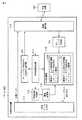
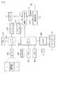
図2には、映像送信装置101または102の構成例が示されている。 FIG. 2 shows a configuration example of the
映像送信装置101または102は、表示装置100との無線通信を実行して映像データを表示装置100に送信する。この映像送信装置101または102は、映像データ出力部111、無線通信部112、通信品質検出部113、ホットプラグ受信部114、送信制御部115、映像データ送信開始制御部116、映像データ送信停止制御部117、変動回数検出部118、閾値変更部119、およびホットプラグ検出信号送信許可通知部120などを備えている。 The
映像データ出力部111は、表示装置100に表示されるべき画面イメージを形成する映像データ(デジタル映像データ)を出力する。映像データの出力は、ホットプラグ検出信号がイネーブル状態になったことに応答して開始される。イネーブル状態のホットプラグ検出信号は表示装置100が映像データを表示可能な状態であることを示し、ディスエーブル状態のホットプラグ検出信号は表示装置100が映像データを表示可能な状態ではないことを示す。映像データ出力部111は、ホットプラグ検出信号がイネーブル状態である場合、映像データを出力し、ホットプラグ検出信号がディスエーブル状態である場合、映像データの出力を停止する。 The video
無線通信部112は、表示装置100との無線通信を実行し、映像データ出力部111から出力される映像データを、表示装置100と無線通信部112との間の無線通信チャネルを介して表示装置100に送信する。無線通信部112は、例えば、UWBを用いて無線通信を実行するUWB無線通信デバイスから構成されている。 The
通信品質検出部113は、表示装置100と無線通信部112との間の無線通信チャネルの通信品質レベルを検出する。通信品質レベルは、無線通信チャネルの無線環境の良好度の程度を表す指標である。例えば、RSSI(Received Signal Strength Indication)レベルのような受信信号強度、リンククオリティ、パケットエラーレート、等を通信品質レベルとして使用することができる。 The communication
ホットプラグ受信部114は、表示装置100から無線通信チャネルを介して送信されるホットプラグ検出信号を受信する。表示装置100が映像送信装置101または102に無線接続された後に、表示装置100は、表示装置100が映像データを表示可能であることを示すホットプラグ検出信号を無線通信チャネルを介して映像送信装置101または102に送信する。この場合、ホットプラグ検出信号をエミュレートするための信号として、例えばビーコン内に属する特定の制御情報(ホットプラグ情報)が用いられる。表示装置100は、映像送信装置101または102に無線接続され、映像データを表示可能な状態になると、以降は、ホットプラグ情報を所定の時間間隔で繰り返し送信する。 The hot
送信制御部115は、映像データの送信開始および送信停止を制御する。映像データの送信開始および送信停止の制御は、映像データ出力部111に入力されるホットプラグ検出信号をイネーブルまたはディスエーブルすることによって行うことができる。送信制御部115は、無線接続環境の瞬時的な変動に起因して映像データの送信開始および送信停止が繰り返されるという事象の発生を防止するために、通信品質レベルに関する2つの独立した閾値(第1の閾値、および第2の閾値)を用いて、ホットプラグ検出信号のイネーブル/ディスエーブルを制御する。第1の閾値は、ホットプラグ検出信号をイネーブルにするための通信品質レベル閾値である。第2の閾値は、ホットプラグ検出信号をディスエーブルにするための通信品質レベル閾値である。換言すれば、第1の閾値はホットプラグ検出信号のディスエーブル状態からイネーブル状態への切り替えを許可する閾値であり、現在の通信品質レベルが第1の閾値を超えない限り、ホットプラグ検出信号のディスエーブル状態からイネーブル状態への切り替えは許可されない。第2の閾値はホットプラグ検出信号のイネーブル状態からディスエーブル状態への切り替えを許可する閾値であり、現在の通信品質レベルが第2の閾値を下回らない限り、ホットプラグ検出信号のイネーブル状態からディスエーブル状態への切り替えは許可されない。 The
第1の閾値と第2の閾値との間にはあるマージンが設けられており、第2の閾値は、第1の閾値よりも小さい。第2の閾値は、例えば、映像データの画質の一定以上の低下を引き起こす通信品質レベル程度の値に設定してもよい。 A margin is provided between the first threshold value and the second threshold value, and the second threshold value is smaller than the first threshold value. For example, the second threshold value may be set to a value of a communication quality level that causes a certain decrease in the image quality of the video data.
これら第1の閾値および第2の閾値を用いてホットプラグ検出信号のイネーブル/ディスエーブルを制御することにより、通信品質がマージンに対応する範囲内で変動している限りは、表示装置100からのホットプラグ情報の一時的な受信の有無による関係なく、ホットプラグ検出信号をイネーブル状態またはディスエーブル状態に維持することができ、無線接続環境の瞬時的な変動に起因して映像データの送信開始および送信停止が繰り返されるという事象の発生を防止することができる。 By controlling the enable / disable of the hot plug detection signal using the first threshold value and the second threshold value, as long as the communication quality varies within the range corresponding to the margin, the display from the
送信制御部115は、映像データ送信開始制御部116と映像データ送信停止制御部117とを備えている。 The
映像データ送信開始制御部116は、ホットプラグ検出信号をイネーブルにすることによって、映像データを無線通信チャネルを介して表示装置100に送信する処理を開始するための制御を行う。 The video data transmission
映像データ送信開始制御部116は、表示装置100への映像データの送信が停止されている状態つまりホットプラグ検出信号がディスエーブルである状態で、通信品質検出部113によって検出された通信品質レベルが第1の閾値を超え、且つ表示装置100から無線通信チャネルを介して送信される、表示装置100が映像データの表示が可能であることを示すホットプラグ検出信号(ホットプラグ情報)がホットプラグ受信部114によって受信された場合、映像データ出力部111に入力されるホットプラグ検出信号をイネーブルにすることによって、映像データを無線通信チャネルを介して表示装置100に送信する処理を開始する。 The video data transmission
すなわち、表示装置100への映像データの送信が停止されている場合には、映像データ送信開始制御部116は、検出された通信品質レベルが第1の閾値を超えるまでは、ホットプラグ受信部114によるホットプラグ検出信号の受信の有無に関係なく、映像データの送信を停止した状態、つまりホットプラグ検出信号をディスエーブル状態に維持する。そして、通信品質検出部113によって検出された通信品質レベルが第1の閾値を超え且つ表示装置100から送信されるホットプラグ検出信号(ホットプラグ情報)がホットプラグ受信部114によって受信されるという条件が満たされた時に、映像データ送信開始制御部116は、映像データ出力部111に入力されるホットプラグ検出信号をイネーブルにすることによって、映像データを無線通信チャネルを介して表示装置100に送信する処理を開始する。 That is, when transmission of video data to the
映像データ送信停止制御部117は、ホットプラグ検出信号をディスエーブルすることによって、映像データを無線通信チャネルを介して表示装置100に送信する処理を停止するための制御を行う。 The video data transmission
映像データ送信停止制御部117は、表示装置100へ映像データを送信する処理が行われている状態つまりホットプラグ検出信号がイネーブルである状態で、通信品質検出部によって検出された通信品質レベルが第2の閾値を下回った場合、映像データ出力部111に入力されるホットプラグ検出信号をディスエーブルにすることによって、表示装置100への映像データの送信を停止する。 The video data transmission
すなわち、表示装置100へ映像データを送信する処理が行われている場合には、映像データ送信停止制御部117は、通信品質検出部113によって検出された通信品質レベルが第2の閾値を下回るまではホットプラグ受信部114によるホットプラグ検出信号(ホットプラグ情報)の受信の有無に関係なく、映像データを送信する処理の実行をしている状態、つまりホットプラグ検出信号をイネーブル状態に維持する。そして、通信品質検出部113によって検出された通信品質レベルが第2の閾値を下回るという条件が満たされた時に、映像データ送信停止制御部117は、ホットプラグ検出信号をディスエーブルにすることによって、映像データを無線通信チャネルを介して表示装置100に送信する処理を停止する。 That is, when the process of transmitting the video data to the
変動回数検出部118および閾値変更部119は、通信品質レベルが短時間の間に激しく変動する場合に、第1の閾値と第2の閾値との間のマージンを自動的に調整するために用いられる。すなわち、変動回数検出部118は、通信品質検出部113によって検出された通信品質レベルが所定期間内に第1の閾値および第2の閾値の双方に跨って変動する回数を検出する。検出された回数が所定回数を超えた場合、閾値変更部119は、第1の閾値および第2の閾値の中から、所定期間内に検出された通信品質レベルの平均値に近い方の閾値を選択し、第1の閾値が選択された場合には第1の閾値を大きくし、第2の閾値が選択された場合には前記第2の閾値を小さくする。この場合、閾値変更部119は、第1の閾値が選択された場合には、第1の閾値を、例えば、所定期間内に検出された通信品質レベルの最大値に設定し、第2の閾値が選択された場合には、第2の閾値を、例えば、所定期間内に検出された通信品質レベルの最小値に設定する。 The fluctuation
ホットプラグ検出信号送信許可通知部120は、必要に応じて、映像送信装置101または102に設けられるオプションデバイスである。このホットプラグ検出信号送信許可通知部120は、表示装置100とのネゴシエーションを実行して、表示装置100によるホットプラグ検出信号の送信を制御する。すなわち、ホットプラグ検出信号送信許可通知部120は、表示装置100への映像データの送信が停止されている状態つまりホットプラグ検出信号がディスエーブルの状態で、通信品質検出部113によって検出された通信品質レベルが第1の閾値を超えた場合、ホットプラグ検出信号の送信の許可を指示する信号を、無線通信チャネルを介して表示装置100に送信する。表示装置100は、ホットプラグ検出信号の送信の許可を指示する信号を受信すると、ホットプラグ検出信号(ホットプラグ情報)の送信を開始する。 The hot plug detection signal transmission
このホットプラグ検出信号送信許可通知部120を設けることにより、表示装置100への映像データの送信が停止されている状態つまりホットプラグ検出信号がディスエーブルの状態においては、無線環境が良好になるまで、表示装置100がホットプラグ検出信号を送信するのを待機させることができる。 By providing the hot plug detection signal transmission
次に、ホットプラグ検出信号の制御方法の例を説明する。なお、以下では、通信品質レベルを示す指標として、RSSI値を使用する場合を想定する。 Next, an example of a method for controlling the hot plug detection signal will be described. In the following, it is assumed that an RSSI value is used as an index indicating the communication quality level.
図3はホットプラグ検出信号のイネーブル/ディスエーブル制御を単一のRSSI閾値Thを用いて行う場合の制御例を示し、図4はホットプラグ検出信号をホットプラグ検出信号のイネーブル/ディスエーブル制御を独立した2つのRSSI閾値Th1,Th2を用いて行う場合の制御例を示している。RSSI閾値Th1は、ホットプラグ検出信号をイネーブルにすることを許可するためのRSSI閾値であり、上述の第1の閾値に対応している。RSSI閾値Th2は、ホットプラグ検出信号をディスエーブルするためのRSSI閾値であり、上述の第2の閾値に対応している。 FIG. 3 shows an example of control when hot plug detection signal enable / disable control is performed using a single RSSI threshold Th, and FIG. 4 shows hot plug detection signal enable / disable control of the hot plug detection signal. The example of control in the case of performing using two independent RSSI threshold values Th1 and Th2 is shown. The RSSI threshold Th1 is an RSSI threshold for allowing the hot plug detection signal to be enabled, and corresponds to the above-described first threshold. The RSSI threshold Th2 is an RSSI threshold for disabling the hot plug detection signal, and corresponds to the above-described second threshold.
RSSI値が時間に対して激しく変動した場合、図3の制御例では、RSSI閾値が一つであるため、ホットプラグ検出信号のイネーブルとホットプラグ検出信号のディスエーブルとが何度も繰り返され、これによって表示装置100の表示画面がちらつくという上記の問題が生じてしまう。なお、RSSI閾値を用いない場合においても、RSSI値の激しく変動により、表示装置100からのホットプラグ検出信号が届いたり、届かなかったりするので、表示装置100の表示画面がちらつくという上記の問題が発生する。 When the RSSI value fluctuates with respect to time, since the RSSI threshold value is one in the control example of FIG. 3, the hot plug detection signal enable and the hot plug detection signal disable are repeated many times. This causes the above problem that the display screen of the
しかし、図4のように、ホットプラグ検出信号をイネーブルにするためのRSSI閾値Th1とホットプラグ検出信号をディスエーブルにするためのRSSI閾値Th2とを独立に設けると、RSSI値の変動を吸収することが可能となり、ホットプラグ検出信号のイネーブルとホットプラグ検出信号のディスエーブルとが何度も繰り返すことを防止することができる。結果として、表示装置100の表示画面のちらつきの発生を防ぐことができる。すなわち、RSSI閾値Th1とRSSI閾値Th2との間のマージンXに対応する範囲は、一種の不感帯として機能する。ホットプラグ検出信号のディスエーブルの状態においては、RSSI値がRSSI閾値Th1を越えない限り、ホットプラグ検出信号はディスエーブル状態に維持され続ける。同様に、ホットプラグ検出信号のイネーブルの状態においては、RSSI値がRSSI閾値Th2を下回らない限り、ホットプラグ検出信号はイネーブル状態に維持され続ける。 However, as shown in FIG. 4, if the RSSI threshold Th1 for enabling the hot plug detection signal and the RSSI threshold Th2 for disabling the hot plug detection signal are provided independently, the fluctuation of the RSSI value is absorbed. Therefore, it is possible to prevent the hot plug detection signal enable and the hot plug detection signal disable from being repeated many times. As a result, it is possible to prevent the display screen of the
次に、図5のフローチャートを参照して、映像送信装置によって実行されるホットプラグ検出信号制御処理の手順を説明する。 Next, the procedure of the hot plug detection signal control process executed by the video transmission apparatus will be described with reference to the flowchart of FIG.
先ず最初に、映像送信装置は、映像データ出力部111に入力されているホットプラグ検出信号の現在のステータスを取得する(ステップS301)。次に、映像送信装置は、現在のRSSI値を通信品質検出部113から取得する(ステップS302)。 First, the video transmission apparatus acquires the current status of the hot plug detection signal input to the video data output unit 111 (step S301). Next, the video transmission apparatus acquires the current RSSI value from the communication quality detection unit 113 (step S302).
上記で取得したホットプラグ検出信号のステータスがディスエーブルであるならば、つまり映像データの送信が停止されている状態であるならば(ステップS303のYES)、映像送信装置は、取得した現在のRSSI値がホットプラグ検出信号をイネーブルするためのRSSI閾値Th1よりも大きく、且つホットプラグ受信部114によって表示装置100からのホットプラグ検出信号(ホットプラグ情報)が受信されるという、ホットプラグ検出信号イネーブル条件が満たされたか否かを判別する(ステップS304)。ホットプラグ検出信号イネーブル条件が満たされたならば(ステップS304のYES)、映像送信装置は、映像データを無線通信チャネルを介して表示装置100に送信する処理を開始するために、映像データ出力部111に入力されるホットプラグ検出信号をイネーブル状態に設定する(ステップS305)。 If the status of the hot plug detection signal acquired above is disabled, that is, if the transmission of video data is stopped (YES in step S303), the video transmission device acquires the current RSSI acquired. The hot plug detection signal enable that the value is larger than the RSSI threshold Th1 for enabling the hot plug detection signal and the hot
上記で取得したホットプラグ検出信号のステータスがイネーブルであるならば、つまり映像データの送信が行われている状態であるならば(ステップS303のNO)、映像送信装置は、取得した現在のRSSI値が、ホットプラグ検出信号をディスエーブルするためのRSSI閾値Th2よりも小さいか否かを判別する(ステップS306)。取得した現在のRSSI値が、ホットプラグ検出信号をディスエーブルするためのRSSI閾値Th2よりも小さいならば(ステップS306のYES)、映像送信装置は、映像データを無線通信チャネルを介して表示装置100に送信する処理を停止するために、映像データ出力部111に入力されるホットプラグ検出信号をディスエーブル状態に設定する(ステップS307)。 If the status of the hot plug detection signal acquired above is enabled, that is, if the video data is being transmitted (NO in step S303), the video transmission apparatus acquires the current RSSI value acquired. Is smaller than the RSSI threshold Th2 for disabling the hot plug detection signal (step S306). If the acquired current RSSI value is smaller than the RSSI threshold Th2 for disabling the hot plug detection signal (YES in step S306), the video transmitting apparatus transmits the video data to the
次に、図6乃至図10を参照して、RSSIの変動の種類の例を説明する。 Next, an example of the type of RSSI variation will be described with reference to FIGS.
図6は、例えば映像送信装置101または102を表示装置100に近づけていく場合に対応するRSSIの変動を示している。このようにRSSIが時間に対して閾値Th2,Th1をまたがって単調増加する場合は、ホットプラグ検出信号をイネーブルするためのRSSI閾値Th1の方が有効となり、ホットプラグ検出信号がイネーブルされる。 FIG. 6 shows the RSSI fluctuation corresponding to the case where the
図7は、例えば映像送信装置101または102を表示装置100から遠ざけていく場合に対応するRSSIの変動を示している。このようにRSSIが時間に対して閾値Th1,Th2をまたがって単調減少する場合は、ホットプラグ検出信号をディスエーブルするためのRSSI閾値Th2の方が有効となり、ホットプラグ検出信号がディスエーブルされる。 FIG. 7 shows the RSSI fluctuation corresponding to the case where the
図8は、干渉などの外乱によってRSSIが単位時間当たりに激しく変動し、かつその変動がホットプラグ検出信号をディスエーブルするためのRSSI閾値Th2のみをまたがる場合を示している。この時は、一度ホットプラグ検出信号がディスエーブルされると、それ以降ホットプラグ検出信号に関して制御を行うことはない。つまり、一度ホットプラグ検出信号がディスエーブルされた後は、表示装置100から送信されるホットプラグ検出信号(ホットプラグ情報)の受信の有無に関係なく、ホットプラグ検出信号はディスエーブル状態に維持され続ける。 FIG. 8 shows a case where the RSSI fluctuates per unit time due to disturbances such as interference, and the fluctuation crosses only the RSSI threshold Th2 for disabling the hot plug detection signal. At this time, once the hot plug detection signal is disabled, the hot plug detection signal is not controlled thereafter. That is, once the hot plug detection signal is disabled, the hot plug detection signal is maintained in a disabled state regardless of whether or not the hot plug detection signal (hot plug information) transmitted from the
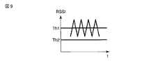
図9は、干渉などの外乱によってRSSIが単位時間当たりに激しく変動し、かつその変動がホットプラグ検出信号をイネーブルするためのRSSI閾値Th1のみをまたがる場合を示している。この時は、一度ホットプラグ検出信号がイネーブルされると、それ以降ホットプラグ検出信号に関して制御を行うことはない。つまり、一度ホットプラグ検出信号がイネーブルされた後は、表示装置100から送信されるホットプラグ検出信号(ホットプラグ情報)の受信の有無に関係なく、ホットプラグ検出信号はイネーブル状態に維持され続ける。 FIG. 9 shows a case where RSSI fluctuates violently per unit time due to disturbance such as interference, and the fluctuation crosses only the RSSI threshold Th1 for enabling the hot plug detection signal. At this time, once the hot plug detection signal is enabled, the hot plug detection signal is not controlled thereafter. That is, once the hot plug detection signal is enabled, the hot plug detection signal continues to be enabled regardless of whether or not the hot plug detection signal (hot plug information) transmitted from the
以上の図6〜図9のケースは、RSSIの変動に対してホットプラグ検出信号がenable/disableを繰り返すことなく安定した制御ができる。 In the cases of FIGS. 6 to 9 described above, stable control can be performed without repeating enable / disable of the hot plug detection signal with respect to the fluctuation of RSSI.
図10は、干渉などの外乱によってRSSIが単位時間当たりに激しく変動し、かつその変動がホットプラグ検出信号をイネーブルするためのRSSI閾値Th1、及びディスエーブルするためのRSSI閾値Th2の両方をまたがる場合を示している。この場合は、図4で示した各閾値間のマージンXを超えてRSSIが変動するために、ホットプラグ検出信号のenable/disableが繰り返されてしまい、結果として映像データの送信/停止が繰り返されてしまう。 FIG. 10 shows a case where RSSI fluctuates per unit time due to disturbances such as interference, and the fluctuation crosses both RSSI threshold Th1 for enabling the hot plug detection signal and RSSI threshold Th2 for disabling. Is shown. In this case, since RSSI fluctuates beyond the margin X between the threshold values shown in FIG. 4, enable / disable of the hot plug detection signal is repeated, and as a result, transmission / stop of video data is repeated. End up.
上記図10の状況を回避するためには、閾値間のマージンXを動的に変化させると良い。マージンXを動的に変化させる処理は、上述の変動回数検出部118および閾値変更部119によって実行される。 In order to avoid the situation of FIG. 10, the margin X between the threshold values may be dynamically changed. The process of dynamically changing the margin X is executed by the above-described variation
次に、図11乃至図13を参照して、RSSI閾値間のマージンを制御する方法の例を説明する。 Next, an example of a method for controlling a margin between RSSI thresholds will be described with reference to FIGS. 11 to 13.
RSSIが変動した時、図11に示すように、映像送信装置は、所定期間内における複数個のRSSIサンプルを取得して、RSSI値が所定期間内に閾値Th1,Th2の双方に跨って変動する回数を検出する。具体的には、映像送信装置は、所定期間内に幾つのRSSIサンプルがホットプラグ検出信号をイネーブルするための閾値Th1を上回り、幾つのRSSIサンプルがホットプラグ検出信号をディスエーブルするための閾値Th2を下回るかをカウントし、ホットプラグ検出信号のenable/disableが何回繰り返しているかを算出する。このenable/disableの繰り返しが基準回数以上ある場合には、この繰り返しを抑えるために、映像送信装置は、閾値間のマージンXを調整する。図11の例では、単位時間当たりに12個のRSSIサンプルを取っており、ホットプラグ検出信号をイネーブルするためのRSSI閾値Th1を4回上回り、ホットプラグ検出信号をディスエーブルするためのRSSI閾値Th2を5回下回っている。そして、結果として、計7回のホットプラグ検出信号のenable/disableの繰り返しが発生している。上記enable/disableの繰り返し回数の基準回数が4回とすると、これを上回っているため、閾値間のマージンXを調整する必要がある。 When the RSSI changes, as shown in FIG. 11, the video transmission apparatus acquires a plurality of RSSI samples within a predetermined period, and the RSSI value changes over both thresholds Th1 and Th2 within the predetermined period. Detect the number of times. Specifically, the video transmission apparatus has a threshold Th2 for disabling the hot plug detection signal and a number of RSSI samples exceeding the threshold Th1 for enabling the hot plug detection signal within a predetermined period. And count how many times the enable / disable of the hot plug detection signal is repeated. If the enable / disable repetition is greater than the reference number, the video transmission apparatus adjusts the margin X between the thresholds in order to suppress the repetition. In the example of FIG. 11, twelve RSSI samples are taken per unit time, which is four times higher than the RSSI threshold Th1 for enabling the hot plug detection signal and RSSI threshold Th2 for disabling the hot plug detection signal. Is 5 times below. As a result, the hot plug detection signal is repeatedly enabled / disabled seven times in total. If the reference number of repeats of enable / disable is 4 times, it exceeds this, so it is necessary to adjust the margin X between the thresholds.
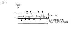
映像送信装置は、図11における単位時間当たりの複数のRSSIサンプルの平均値を算出する。図12は、RSSIサンプルの平均値を示している。図中の点線が平均値を示している。次に、映像送信装置は、平均値と各RSSI閾値Th1,Th2とを比較して、その差が小さい方の閾値を、ホットプラグ検出信号のenable/disableが発生しないように変化させる。具体的には、映像送信装置は、図12において算出した平均値とホットプラグ検出信号を制御するための各RSSI閾値Th1,Th2とを比較して、RSSI閾値Th1,Th2の中から、平均値に近い方の閾値を選択する。選択された閾値が、ホットプラグ検出信号をイネーブルするためのRSSI閾値Th1であった場合は、映像送信装置は、そのRSSI閾値Th1閾値を大きくする。この場合、RSSI閾値Th1を、所定期間内に取得されたRSSIサンプルの最大値に設定すると良い。一方、選択された閾値が、ホットプラグ検出信号をディスエーブルするためのRSSI閾値Th2であった場合は、映像送信装置は、そのRSSI閾値Th2を小さくする。この場合、図13に示すように、RSSI閾値Th2を下げて、RSSI閾値Th2を、所定期間内に取得されたRSSIサンプルの最小値に設定すると良い。 The video transmitting apparatus calculates an average value of a plurality of RSSI samples per unit time in FIG. FIG. 12 shows the average value of the RSSI samples. The dotted line in the figure shows the average value. Next, the video transmission device compares the average value with each RSSI threshold Th1, Th2, and changes the threshold with the smaller difference so that hot plug detection signal enable / disable does not occur. Specifically, the video transmitting apparatus compares the average value calculated in FIG. 12 with the RSSI threshold values Th1 and Th2 for controlling the hot plug detection signal, and determines the average value from the RSSI threshold values Th1 and Th2. The threshold value closer to is selected. When the selected threshold value is the RSSI threshold value Th1 for enabling the hot plug detection signal, the video transmission device increases the RSSI threshold value Th1 threshold value. In this case, the RSSI threshold Th1 may be set to the maximum value of the RSSI samples acquired within a predetermined period. On the other hand, when the selected threshold value is the RSSI threshold value Th2 for disabling the hot plug detection signal, the video transmission apparatus decreases the RSSI threshold value Th2. In this case, as shown in FIG. 13, the RSSI threshold Th <b> 2 may be lowered and the RSSI threshold Th <b> 2 may be set to the minimum value of the RSSI samples acquired within a predetermined period.
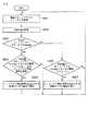
次に、図6のフローチャートを参照して、RSSI閾値間のマージンを制御するための処理を説明する。 Next, processing for controlling the margin between RSSI thresholds will be described with reference to the flowchart of FIG.
先ず、映像送信装置は、所定期間内のRSSIサンプルを複数個(A個)分取得する(ステップS601)。次に、映像送信装置は、取得したRSSIサンプルに基づいて、ホットプラグ検出信号のenable/disableが繰り返された回数、つまりRSSI値が所定期間内に閾値Th1およびTh2の双方に跨って変動した回数、を算出する(ステップS602)。 First, the video transmission apparatus acquires a plurality (A) of RSSI samples within a predetermined period (step S601). Next, the video transmission device, based on the acquired RSSI sample, the number of times the enable / disable of the hot plug detection signal is repeated, that is, the number of times that the RSSI value fluctuates over both thresholds Th1 and Th2 within a predetermined period. Are calculated (step S602).
ホットプラグ検出信号のenable/disableが繰り返された回数、つまりRSSI値が所定期間内に閾値Th1およびTh2の双方に跨って変動した回数が、所定回数(B回)未満ならば(ステップS603のNO)、映像送信装置は、ステップS601に戻り、(一定時間後)再びRSSIのサンプル取得を行う。 If the number of times the enable / disable of the hot plug detection signal is repeated, that is, the number of times the RSSI value fluctuates over both the thresholds Th1 and Th2 within a predetermined period is less than the predetermined number (B times) (NO in step S603) ), The video transmission apparatus returns to step S601, and again performs RSSI sample acquisition (after a certain period of time).
一方、ホットプラグ検出信号のenable/disableが繰り返された回数、つまりRSSI値が所定期間内に閾値Th1およびTh2の双方に跨って変動した回数がB回以上ならば(ステップS603のYES)、映像送信装置は、取得したRSSIサンプルの平均値Cを算出する(ステップS604)。次いで、映像送信装置は、平均値Cを、閾値Th1と閾値Th2との平均値と比較し、平均値Cが、閾値Th1と閾値Th2との平均値よりも大きいか否かを判別する(ステップS605)。 On the other hand, if the number of times the enable / disable of the hot plug detection signal is repeated, that is, the number of times that the RSSI value fluctuates across both the thresholds Th1 and Th2 within a predetermined period is B times or more (YES in step S603), the video The transmission device calculates an average value C of the acquired RSSI samples (step S604). Next, the video transmitting apparatus compares the average value C with the average value of the threshold value Th1 and the threshold value Th2, and determines whether or not the average value C is larger than the average value of the threshold value Th1 and the threshold value Th2 (step). S605).
平均値Cが閾値Th1と閾値Th2との平均値よりも大きいならば、つまり平均値Cに近い方の閾値が閾値Th1であるならば(ステップS605のYES)、映像送信装置は、閾値Th1を、取得したA個のRSSIサンプルの最大値まで上げる(ステップS606)。 If the average value C is larger than the average value of the threshold value Th1 and the threshold value Th2, that is, if the threshold value closer to the average value C is the threshold value Th1 (YES in step S605), the video transmitting apparatus sets the threshold value Th1. The acquired A RSSI samples are increased to the maximum value (step S606).
平均値Cが閾値Th1と閾値Th2との平均値よりも小さいならば、つまり平均値Cに近い方の閾値が閾値Th2であるならば(ステップS605のNO)、映像送信装置は、閾値Th2を、取得したA個のRSSIサンプルの最小値まで下げる(ステップS607)。 If the average value C is smaller than the average value of the threshold value Th1 and the threshold value Th2, that is, if the threshold value closer to the average value C is the threshold value Th2 (NO in step S605), the video transmitting apparatus sets the threshold value Th2. Then, it is lowered to the minimum value of the acquired A RSSI samples (step S607).
図14の処理は例えば一定時間毎に繰り返し実行される。これにより、ホットプラグ検出信号を制御するためのRSSI閾値間のマージンを適切に調整することが可能となる。 The process of FIG. 14 is repeatedly executed at regular time intervals, for example. This makes it possible to appropriately adjust the margin between RSSI thresholds for controlling the hot plug detection signal.
これまで、上記で述べてきたRSSI値及びRSSIサンプル値としては、スパイク的なRSSI値の変化による影響を避けるために、幾つかのRSSI値の平均値を用いてもよい。また、上記の実施例では、無線環境を表す指標としてRSSIを用いているが、パケットエラーレートやリンククオリィティ等無線環境を表す別の指標でも適用することができる。 Up to now, as the RSSI value and the RSSI sample value described above, an average value of several RSSI values may be used in order to avoid the influence due to the spiked RSSI value change. In the above embodiment, RSSI is used as an index representing the wireless environment. However, other indices representing the wireless environment such as a packet error rate and a link quality can be applied.
以上のように、本実施形態においては、ホットプラグ検出信号をenable/disableするためのRSSI閾値を独立に設け、さらにそれらの閾値間のマージンを動的に変動させることで、無線の接続状態によってホットプラグ検出用信号がenableとdisableを繰り返すという問題を解決することができる。これにより、映像データの送信と送信停止とが繰り返されて、表示装置100の画面イメージがちらつくといったユーザにとって不快な現象の発生を可能な限り避けることができる。 As described above, in the present embodiment, the RSSI threshold value for enabling / disabling the hot plug detection signal is independently provided, and the margin between the threshold values is dynamically changed to change the wireless connection state. The problem that the hot plug detection signal repeats enable and disable can be solved. As a result, it is possible to avoid the occurrence of a phenomenon unpleasant for the user, such as flickering of the screen image of the
なお、以上の説明では通信品質レベルとしてRSSI値を用いる場合を説明したが、RSSI値に限らず、リンククオリティーレベル、パケットエラーレート等を通信品質レベルとして使用しても良い。例えば、リンククオリティーレベルを通信品質レベルとして使用した場合には、ホットプラグ検出信号をイネーブルするための第1の閾値として第1のリンククオリティーレベル閾値が用いられ、またホットプラグ検出信号をディスエーブルするための第2の閾値として、第1のリンククオリティーレベル閾値よりも低い第2のリンククオリティーレベル閾値が用いられる。 In the above description, the RSSI value is used as the communication quality level. However, not only the RSSI value but also a link quality level, a packet error rate, and the like may be used as the communication quality level. For example, when the link quality level is used as the communication quality level, the first link quality level threshold is used as the first threshold for enabling the hot plug detection signal, and the hot plug detection signal is disabled. For this purpose, a second link quality level threshold value lower than the first link quality level threshold value is used.
次に、図15を参照して、本実施形態の映像送信装置をPC101によって実現した場合のハードウェア構成の例を説明する。 Next, with reference to FIG. 15, an example of a hardware configuration when the video transmission apparatus of the present embodiment is realized by the
PC101は、上述の映像データ出力部111および無線通信部112に加え、CPU211、ノースブリッジ212、主メモリ213、グラフィックスコントローラ214、サウンドコントローラ215、サウスブリッジ219、BIOS−ROM220、ハードディスクドライブ(HDD)221、光ディスクドライブ(ODD)222、およびエンベデッドコントローラ/キーボードコントローラIC(EC/KBC)225等を備えている。 In addition to the video
CPU211はPC101の動作を制御するプロセッサであり、ハードディスクドライブ(HDD)221から主メモリ113にロードされる、オペレーティングシステム(OS)および各種アプリケーション/ユーティリティプログラムを実行する。アプリケーション/ユーティリティプログラムには、通信制御プログラムが含まれている。この通信制御プログラムは、無線通信部112を制御するためのプログラムである。 The
またCPU111は、BIOS−ROM220に格納されたBIOS(Basic Input Output System)も実行する。BIOSはハードウェア制御のためのプログラムである。 The
ノースブリッジ212は、CPU211のローカルバスとサウスブリッジ219との間を接続するブリッジデバイスである。またノースブリッジ212は、グラフィクスコントローラ214との通信を実行する機能も有している。 The
グラフィクスコントローラ214は、PC101のディスプレイモニタとして使用されるLCD(Liquid Crystal Display)17を制御する表示コントローラである。このグラフィクスコントローラ214によって生成される映像信号はLCD17に送られる。また、グラフィクスコントローラ214は、映像データ出力部111にデジタル映像信号を送出することもできる。 The
サウスブリッジ219は各種I/Oデバイスを制御するブリッジデバイスである。サウスブリッジ219には、映像データ出力部111および無線通信部112がそれぞれ接続されている。エンベデッドコントローラ/キーボードコントローラIC(EC/KBC)225は、電力管理のためのエンベデッドコントローラと、キーボード(KB)13およびタッチパッド16を制御するためのキーボードコントローラとが集積された1チップマイクロコンピュータである。 The
映像データ出力部111は、グラフィクスコントローラ214から出力される映像信号を所定フォーマットの送信データDATAに変換し、その送信データDATAを無線通信部112に送出する。送信データDATAへの変換処理においては、必要に応じて、グラフィクスコントローラ214から出力される映像信号を圧縮符号化する処理を行うことも出来る。また、映像データ出力部111は、サウンドコントローラ215から出力されるオーディオ信号を送信データDATAとして無線通信部112に送出することもできる。 The video
例えば、図2で説明した通信品質検出部113、ホットプラグ受信部114、送信制御部115、変動回数検出部118、閾値変更部119、およびホットプラグ検出信号送信許可通知部120それぞれの機能は、CPU211によって実行される通信制御プログラムによって実現することができる。この場合、図5のフローチャートで説明した処理、および図14のフローチャートで説明した処理は、それぞれCPU211によって実行することが出来る。もちろん、図2で説明した通信品質検出部113、ホットプラグ受信部114、送信制御部115、変動回数検出部118、閾値変更部119、およびホットプラグ検出信号送信許可通知部120の機能をそれぞれ専用の回路によって実現したり、またこれら機能をマイクロコンピュータやDSP等によって実現してもよい。 For example, the functions of the communication
なお、本発明は、上記実施形態そのままに限定されるものではなく、実施段階ではその要旨を逸脱しない範囲で構成要素を変形して具体化できる。また、上記実施形態に開示されている複数の構成要素の適宜な組み合わせにより種々の発明を形成できる。例えば、実施形態に示される全構成要素から幾つかの構成要素を削除してもよい。更に、異なる実施形態に構成要素を適宜組み合わせてもよい。 Note that the present invention is not limited to the above-described embodiment as it is, and can be embodied by modifying the constituent elements without departing from the scope of the invention in the implementation stage. In addition, various inventions can be formed by appropriately combining a plurality of components disclosed in the embodiment. For example, some components may be deleted from all the components shown in the embodiment. Furthermore, you may combine a component suitably in different embodiment.
100…表示装置、101…PC、102…DVDプレーヤ、111…映像データ出力部、112…無線通信部、113…通信品質検出部、116…映像データ送信開始制御部、117…映像データ送信停止制御部。 DESCRIPTION OF
Claims (11)
Translated fromJapanese前記表示装置との無線通信を実行し、前記映像データ出力部から出力される前記映像データを前記表示装置に送信する無線通信部と、
前記表示装置と前記無線通信部との間を無線接続する無線通信チャネルの通信品質レベルを検出する通信品質検出手段と、
前記表示装置から前記無線通信チャネルを介して送信される、前記表示装置が映像データの表示が可能であることを示すホットプラグ情報を受信する受信手段と、
前記検出された通信品質レベルが第1の閾値を超え、且つ、前記ホットプラグ情報が受信された場合、前記ホットプラグ検出信号をイネーブル状態に設定することによって、前記映像データを前記無線通信チャネルを介して前記表示装置に送信する処理を開始する映像データ送信開始制御手段と、
前記検出された通信品質レベルが前記第1の閾値よりも低い第2の閾値を下回った場合、前記ホットプラグ検出信号をディスエーブル状態に設定することによって、前記表示装置への前記映像データの送信を停止する映像データ送信停止制御手段とを具備することを特徴とする映像送信装置。When the hot plug detection signal indicating that the display device can display the video data is enabled, the video data is output, and when the hot plug detection signal is disabled, the video data is output. The video data output section to stop,
A wireless communication unit that performs wireless communication with the display device and transmits the video data output from the video data output unit to the display device;
Communication quality detecting means for detecting a communication quality level of a wireless communication channel for wirelessly connecting the display device and thewireless communication unit ;
Receiving means for receiving hot plug information transmitted from the display device via the wireless communication channel and indicating that the display device is capable of displaying video data;
Before Symbol detected communication quality level exceeds a first threshold, and, whensaid hot pluginformation is received,the by setting the hot plug detect signal to the enable state, the image data the wireless communication channel Video data transmission start control means for starting processing to transmit to the display device via
Ifthe previous SL detected communication quality level is below the second threshold lower than the first threshold value,by setting the hot plug detect signal to the disable state, the image data to the display device A video transmission apparatus comprising: video data transmission stop control means for stopping transmission.
前記検出された回数が所定回数を超えた場合、前記第1の閾値の大きい値への変更、又は前記第2の閾値の小さい値への変更の少なくとも一方の閾値の変更を行う閾値変更手段とをさらに具備することを特徴とする請求項1記載の映像送信装置。A fluctuation number detecting means for detecting the number of times that the detected communication quality level fluctuates across both the first threshold value and the second threshold value within a predetermined period;
Threshold value changing means for changing the threshold value of at least one of changing the first threshold value to a larger value or changing the second threshold value to a smaller value when the detected number of times exceeds a predetermined number of times; The video transmission apparatus according to claim 1, further comprising:
前記表示装置との無線通信を実行し、前記映像データ出力部から出力される前記映像データを、前記表示装置と前記無線通信部との間の無線通信チャネルを介して前記表示装置に送信する無線通信部と、
前記無線通信チャネルの通信品質レベルを検出する通信品質検出手段と、
前記表示装置から前記無線通信チャネルを介して送信される、前記表示装置が映像データの表示が可能であることを示すホットプラグ情報を受信する受信手段と、
前記ホットプラグ検出信号がディスエーブル状態に設定されている場合、前記検出された通信品質レベルが前記ホットプラグ検出信号をイネーブルにするための第1の閾値を超えるまでは前記ホットプラグ情報の受信の有無に関係なく前記ホットプラグ検出信号をディスエーブル状態に維持し、前記検出された通信品質レベルが前記第1の閾値を超え且つ前記ホットプラグ情報が受信されるという条件が満たされた場合、前記映像データを前記無線通信チャネルを介して前記表示装置に送信するために、前記ホットプラグ検出信号をイネーブル状態に設定する処理を実行するホットプラグ検出信号イネーブル制御手段と、
前記ホットプラグ検出信号がイネーブル状態に設定されている場合、前記検出された通信品質レベルが、前記第1の閾値よりも低い、前記ホットプラグ検出信号をディスエーブルするための第2の閾値を下回るまでは前記ホットプラグ情報の受信の有無に関係なく前記ホットプラグ検出信号をイネーブル状態に維持し、前記ホットプラグ検出信号がイネーブル状態に設定されている状態で、前記検出された通信品質レベルが前記第2の閾値を下回るという条件が満たされた場合、前記表示装置への前記映像データの送信を停止するために、前記ホットプラグ検出信号をディスエーブル状態に設定する処理を実行するホットプラグ検出信号ディスエーブル制御手段とを具備することを特徴とする映像データ送信装置。When the hot plug detection signal indicating that the display device can display the video data is enabled, the video data is output, and when the hot plug detection signal is disabled, the video data is output. The video data output section to stop,
Wireless communication that executes wireless communication with the display device and transmits the video data output from the video data output unit to the display device via a wireless communication channel between the display device and the wireless communication unit. A communication department;
Communication quality detecting means for detecting a communication quality level of the wireless communication channel;
Receiving means for receiving hot plug information transmitted from the display device via the wireless communication channel and indicating that the display device is capable of displaying video data;
When the hot plug detection signal is set to a disabled state, reception of the hot plug information is not performed until the detected communication quality level exceeds a first threshold value for enabling the hot plug detection signal. The hot plug detection signal is maintained in a disabled state regardless of the presence or absence, and when the condition that the detected communication quality level exceeds the first threshold and the hot plug information is received is satisfied, Hot plug detection signal enable control means for executing processing for setting the hot plug detection signal to an enable state in order to transmit video data to the display device via the wireless communication channel;
When the hot plug detection signal is set to an enabled state, the detected communication quality level is lower than the first threshold and lower than a second threshold for disabling the hot plug detection signal. Until the hot plug detection signal is enabled regardless of whether or not the hot pluginformation is received, the detected communication quality level is the state in which the hot plug detection signal is set to the enabled state. A hot plug detection signal that executes processing for setting the hot plug detection signal to a disabled state in order to stop transmission of the video data to the display device when a condition that the value is lower than a second threshold is satisfied A video data transmitting apparatus comprising a disable control means.
前記表示装置が前記映像データの表示が可能であることを示すホットプラグ検出信号がイネーブル状態である場合、前記映像データを出力し、前記ホットプラグ検出信号がディスエーブル状態である場合、前記映像データの出力を停止するステップと、
前記出力される映像データを前記無線通信チャネルを介して前記表示装置に送信するステップと、
前記無線通信チャネルの通信品質レベルを検出するステップと、
前記表示装置から前記無線通信チャネルを介して送信される、前記表示装置が前記映像データの表示が可能であることを示すホットプラグ情報を受信するステップと、
前記検出された通信品質レベルが第1の閾値を超え、且つ前記ホットプラグ情報が受信された場合、前記ホットプラグ検出信号をイネーブル状態に設定することによって、前記映像データを前記無線通信チャネルを介して前記表示装置に送信する処理を開始するステップと、
前記検出された通信品質レベルが前記第1の閾値よりも低い第2の閾値を下回った場合、前記ホットプラグ検出信号をイネーブル状態に設定することによって、前記表示装置への前記映像データの送信を停止するステップとを具備することを特徴とする映像送信方法。A video transmission method for transmitting video data from the video transmission device to the display device via a wireless communication channel for wireless connection between the video transmission device and the display device,
When thehot plug detection signal indicating that the display device is capable of displaying the video data is enabled, the video data is output, and when the hot plug detection signal is disabled, the video data A step of stopping the output of
Transmitting the output video data to the display device via the wireless communication channel;
Detecting a communication quality level of the wireless communication channel;
Receiving hot plug information transmitted from the display device via the wireless communication channel and indicating that the display device is capable of displaying the video data;
Before Symbol detected communication quality level exceeds a first threshold value, and whensaid hot plug information is received,by setting the hot plug detect signal to the enable state, the wireless communication channel the video data Starting the process of transmitting to the display device via,
Ifthe previous SL detected communication quality level is below the second threshold lower than the first threshold value,by setting the hot plug detect signal to the enable state, the transmission of the image data to the display device And a step of stopping the transmission.
前記検出された回数が所定回数を超えた場合、前記第1の閾値および前記第2の閾値の中から、前記所定期間内に検出された通信品質レベルの平均値に近い方の閾値を選択し、前記第1の閾値が選択された場合には前記第1の閾値を大きくし、前記第2の閾値が選択された場合には前記第2の閾値を小さくする閾値変更ステップとをさらに具備することを特徴とする請求項9記載の映像送信方法。Detecting the number of times that the detected communication quality level fluctuates across both the first threshold and the second threshold within a predetermined period;
When the detected number of times exceeds a predetermined number of times, a threshold value closer to an average value of communication quality levels detected within the predetermined period is selected from the first threshold value and the second threshold value. A threshold value changing step of increasing the first threshold value when the first threshold value is selected and decreasing the second threshold value when the second threshold value is selected. The video transmission method according to claim9 .
Priority Applications (2)
| Application Number | Priority Date | Filing Date | Title |
|---|---|---|---|
| JP2007154487AJP5060177B2 (en) | 2007-06-11 | 2007-06-11 | Video transmission apparatus and video transmission method |
| US12/135,558US8223273B2 (en) | 2007-06-11 | 2008-06-09 | Video transmission apparatus and video transmission method |
Applications Claiming Priority (1)
| Application Number | Priority Date | Filing Date | Title |
|---|---|---|---|
| JP2007154487AJP5060177B2 (en) | 2007-06-11 | 2007-06-11 | Video transmission apparatus and video transmission method |
Related Child Applications (1)
| Application Number | Title | Priority Date | Filing Date |
|---|---|---|---|
| JP2012164623ADivisionJP2012231534A (en) | 2012-07-25 | 2012-07-25 | Wireless device and control method |
Publications (2)
| Publication Number | Publication Date |
|---|---|
| JP2008306687A JP2008306687A (en) | 2008-12-18 |
| JP5060177B2true JP5060177B2 (en) | 2012-10-31 |
Family
ID=40095528
Family Applications (1)
| Application Number | Title | Priority Date | Filing Date |
|---|---|---|---|
| JP2007154487AExpired - Fee RelatedJP5060177B2 (en) | 2007-06-11 | 2007-06-11 | Video transmission apparatus and video transmission method |
Country Status (2)
| Country | Link |
|---|---|
| US (1) | US8223273B2 (en) |
| JP (1) | JP5060177B2 (en) |
Families Citing this family (15)
| Publication number | Priority date | Publication date | Assignee | Title |
|---|---|---|---|---|
| JP4497332B2 (en)* | 2008-02-06 | 2010-07-07 | セイコーエプソン株式会社 | Digital signal processing device, display device, and program |
| US20100086279A1 (en)* | 2008-10-05 | 2010-04-08 | Harris Scott C | Video BoomBox |
| WO2010055697A1 (en) | 2008-11-17 | 2010-05-20 | パナソニック株式会社 | Wireless communication apparatus and wireless communication method |
| US9048947B2 (en)* | 2008-12-10 | 2015-06-02 | Verizon Patent And Licensing Inc. | Optical receiver having an automatic fiber optic signal adjustment circuit |
| WO2010131389A1 (en)* | 2009-05-11 | 2010-11-18 | パナソニック株式会社 | Receiver |
| TW201119437A (en)* | 2009-11-24 | 2011-06-01 | Grandex Internat Corp | Apparatus and method for automatic wireless link replacement |
| US8868811B2 (en)* | 2011-10-03 | 2014-10-21 | Via Technologies, Inc. | Systems and methods for hot-plug detection recovery |
| JP5853862B2 (en)* | 2012-05-23 | 2016-02-09 | ソニー株式会社 | Information processing apparatus, information processing system, and information processing method |
| DE102013201649A1 (en)* | 2013-01-31 | 2014-07-31 | Sennheiser Electronic Gmbh & Co. Kg | Wireless audio transmission system and method for wireless audio transmission |
| US20140320510A1 (en)* | 2013-04-24 | 2014-10-30 | Nvidia Corporation | Detection of a hot-plug event of coupling a target display in a standby mode to a source device to enable automatic transitioning of the target display to an active mode of operation thereof |
| US9257097B2 (en)* | 2013-12-23 | 2016-02-09 | Qualcomm Incorporated | Remote rendering for efficient use of wireless bandwidth for wireless docking |
| US10410511B2 (en)* | 2014-10-31 | 2019-09-10 | Siemens Aktiengesellschaft | Method, digital tool, device and system for detecting movements of objects and/or living beings in a radio range, in particular of an indoor area |
| US10397065B2 (en)* | 2016-12-16 | 2019-08-27 | General Electric Company | Systems and methods for characterization of transient network conditions in wireless local area networks |
| JP2022139156A (en)* | 2021-03-11 | 2022-09-26 | オムロン株式会社 | Receiver, transmitter, radio communication system, radio communication method, and program |
| CN114760429A (en)* | 2022-05-10 | 2022-07-15 | 宏晶微电子科技股份有限公司 | Video image transmission control method, device and system |
Family Cites Families (7)
| Publication number | Priority date | Publication date | Assignee | Title |
|---|---|---|---|---|
| JP4058834B2 (en)* | 1998-04-09 | 2008-03-12 | ソニー株式会社 | Digital broadcast receiver and reception control method |
| JP2001078180A (en)* | 1999-09-07 | 2001-03-23 | Hitachi Ltd | Digital broadcast receiver and transmission path decoder |
| JP4024776B2 (en)* | 2003-04-16 | 2007-12-19 | シャープ株式会社 | Wireless terminal, wireless system, wireless terminal control method, control program, and computer-readable recording medium recording the same |
| JP2004350168A (en)* | 2003-05-26 | 2004-12-09 | Sony Corp | Radio communication device, radio communication method, and computer program |
| US20060209892A1 (en)* | 2005-03-15 | 2006-09-21 | Radiospire Networks, Inc. | System, method and apparatus for wirelessly providing a display data channel between a generalized content source and a generalized content sink |
| CN101278268B (en)* | 2005-09-30 | 2010-09-29 | 松下电器产业株式会社 | wireless transmission system |
| JP4318050B2 (en)* | 2006-01-24 | 2009-08-19 | ソニー株式会社 | Wireless channel determination and selection method and access point device |
- 2007
- 2007-06-11JPJP2007154487Apatent/JP5060177B2/ennot_activeExpired - Fee Related
- 2008
- 2008-06-09USUS12/135,558patent/US8223273B2/ennot_activeExpired - Fee Related
Also Published As
| Publication number | Publication date |
|---|---|
| US20080303956A1 (en) | 2008-12-11 |
| JP2008306687A (en) | 2008-12-18 |
| US8223273B2 (en) | 2012-07-17 |
Similar Documents
| Publication | Publication Date | Title |
|---|---|---|
| JP5060177B2 (en) | Video transmission apparatus and video transmission method | |
| US8026924B2 (en) | Display system and method for displaying video signals | |
| US7523241B2 (en) | Hot-plug signal detecting apparatus, source device and repeater device | |
| US20060294230A1 (en) | Information processing apparatus and connection control method for the apparatus | |
| US8570241B2 (en) | Image display apparatus for controlling an external data transmitting device using a USB connector and a method thereof | |
| JP4768861B2 (en) | Information processing apparatus and audio output control method in information processing apparatus | |
| JP2010015403A (en) | Cec communication equipment, video acoustic device using the same and cec communication method | |
| EP3179332A1 (en) | Wireless docking station and method to connect to a docking station | |
| US20150126121A1 (en) | Display apparatus and method of controlling display apparatus | |
| TWI486786B (en) | Method and apparatus of data transfer dynamic adjustment in response to usage scenarios, and associated computer program product | |
| US8891015B2 (en) | Electronic apparatus and display control method | |
| US20140240202A1 (en) | Information processing method and apparatus for electronic device | |
| US20140099040A1 (en) | Image processing device and image processing method | |
| JP5193523B2 (en) | Information processing apparatus and output switching control method | |
| EP2560381A1 (en) | Wireless device and communication method | |
| CN107658924B (en) | A wireless charging method and mobile terminal | |
| JPWO2017158672A1 (en) | Image transmission apparatus, image transmission system, and image transmission apparatus control method | |
| JP2011019098A (en) | Communication system | |
| JP2012231534A (en) | Wireless device and control method | |
| US20160028357A1 (en) | Display device, body device, and information processing device | |
| US20180260013A1 (en) | Communication device, information processing device, and communication method | |
| JP2000322036A (en) | Computer monitor provided with two functional operation switch and method providing different functions for screen operation switch of computer monitor | |
| US8843067B2 (en) | Wireless communications apparatus and wireless communications method | |
| CN113491119A (en) | Image transmission control method and device, electronic equipment and image transmission system | |
| CN102955666B (en) | Method for automatically adjusting wireless display quality, display device and communication device thereof |
Legal Events
| Date | Code | Title | Description |
|---|---|---|---|
| A621 | Written request for application examination | Free format text:JAPANESE INTERMEDIATE CODE: A621 Effective date:20100224 | |
| A977 | Report on retrieval | Free format text:JAPANESE INTERMEDIATE CODE: A971007 Effective date:20120419 | |
| A131 | Notification of reasons for refusal | Free format text:JAPANESE INTERMEDIATE CODE: A131 Effective date:20120424 | |
| RD04 | Notification of resignation of power of attorney | Free format text:JAPANESE INTERMEDIATE CODE: A7424 Effective date:20120529 | |
| A521 | Request for written amendment filed | Free format text:JAPANESE INTERMEDIATE CODE: A523 Effective date:20120622 | |
| TRDD | Decision of grant or rejection written | ||
| A01 | Written decision to grant a patent or to grant a registration (utility model) | Free format text:JAPANESE INTERMEDIATE CODE: A01 Effective date:20120710 | |
| A01 | Written decision to grant a patent or to grant a registration (utility model) | Free format text:JAPANESE INTERMEDIATE CODE: A01 | |
| A61 | First payment of annual fees (during grant procedure) | Free format text:JAPANESE INTERMEDIATE CODE: A61 Effective date:20120803 | |
| FPAY | Renewal fee payment (event date is renewal date of database) | Free format text:PAYMENT UNTIL: 20150810 Year of fee payment:3 | |
| FPAY | Renewal fee payment (event date is renewal date of database) | Free format text:PAYMENT UNTIL: 20150810 Year of fee payment:3 | |
| LAPS | Cancellation because of no payment of annual fees |