JP5059304B2 - Apparatus and method for detecting and correcting failure trends in data storage arrays - Google Patents
Apparatus and method for detecting and correcting failure trends in data storage arraysDownload PDFInfo
- Publication number
- JP5059304B2 JP5059304B2JP2005202408AJP2005202408AJP5059304B2JP 5059304 B2JP5059304 B2JP 5059304B2JP 2005202408 AJP2005202408 AJP 2005202408AJP 2005202408 AJP2005202408 AJP 2005202408AJP 5059304 B2JP5059304 B2JP 5059304B2
- Authority
- JP
- Japan
- Prior art keywords
- data
- data storage
- storage devices
- log
- controller
- Prior art date
- Legal status (The legal status is an assumption and is not a legal conclusion. Google has not performed a legal analysis and makes no representation as to the accuracy of the status listed.)
- Expired - Fee Related
Links
Images


Classifications
- G—PHYSICS
- G06—COMPUTING OR CALCULATING; COUNTING
- G06F—ELECTRIC DIGITAL DATA PROCESSING
- G06F11/00—Error detection; Error correction; Monitoring
- G06F11/07—Responding to the occurrence of a fault, e.g. fault tolerance
- G06F11/0703—Error or fault processing not based on redundancy, i.e. by taking additional measures to deal with the error or fault not making use of redundancy in operation, in hardware, or in data representation
- G06F11/0751—Error or fault detection not based on redundancy
- G—PHYSICS
- G06—COMPUTING OR CALCULATING; COUNTING
- G06F—ELECTRIC DIGITAL DATA PROCESSING
- G06F11/00—Error detection; Error correction; Monitoring
- G06F11/07—Responding to the occurrence of a fault, e.g. fault tolerance
- G06F11/0703—Error or fault processing not based on redundancy, i.e. by taking additional measures to deal with the error or fault not making use of redundancy in operation, in hardware, or in data representation
- G06F11/0706—Error or fault processing not based on redundancy, i.e. by taking additional measures to deal with the error or fault not making use of redundancy in operation, in hardware, or in data representation the processing taking place on a specific hardware platform or in a specific software environment
- G06F11/0727—Error or fault processing not based on redundancy, i.e. by taking additional measures to deal with the error or fault not making use of redundancy in operation, in hardware, or in data representation the processing taking place on a specific hardware platform or in a specific software environment in a storage system, e.g. in a DASD or network based storage system
- G—PHYSICS
- G11—INFORMATION STORAGE
- G11B—INFORMATION STORAGE BASED ON RELATIVE MOVEMENT BETWEEN RECORD CARRIER AND TRANSDUCER
- G11B27/00—Editing; Indexing; Addressing; Timing or synchronising; Monitoring; Measuring tape travel
- G11B27/36—Monitoring, i.e. supervising the progress of recording or reproducing
- G—PHYSICS
- G06—COMPUTING OR CALCULATING; COUNTING
- G06F—ELECTRIC DIGITAL DATA PROCESSING
- G06F11/00—Error detection; Error correction; Monitoring
- G06F11/07—Responding to the occurrence of a fault, e.g. fault tolerance
- G06F11/0703—Error or fault processing not based on redundancy, i.e. by taking additional measures to deal with the error or fault not making use of redundancy in operation, in hardware, or in data representation
- G06F11/0793—Remedial or corrective actions
- G—PHYSICS
- G11—INFORMATION STORAGE
- G11B—INFORMATION STORAGE BASED ON RELATIVE MOVEMENT BETWEEN RECORD CARRIER AND TRANSDUCER
- G11B2220/00—Record carriers by type
- G11B2220/20—Disc-shaped record carriers
- G11B2220/25—Disc-shaped record carriers characterised in that the disc is based on a specific recording technology
- G11B2220/2508—Magnetic discs
- G11B2220/2516—Hard disks
- G—PHYSICS
- G11—INFORMATION STORAGE
- G11B—INFORMATION STORAGE BASED ON RELATIVE MOVEMENT BETWEEN RECORD CARRIER AND TRANSDUCER
- G11B2220/00—Record carriers by type
- G11B2220/40—Combinations of multiple record carriers
- G11B2220/41—Flat as opposed to hierarchical combination, e.g. library of tapes or discs, CD changer, or groups of record carriers that together store one title
Landscapes
- Engineering & Computer Science (AREA)
- Theoretical Computer Science (AREA)
- Quality & Reliability (AREA)
- Physics & Mathematics (AREA)
- General Engineering & Computer Science (AREA)
- General Physics & Mathematics (AREA)
- Debugging And Monitoring (AREA)
Description
Translated fromJapanese本請求になる発明は、一般的には、データ記憶システムの分野に関し、特に、限定する意図ではないが、データ記憶アレイにおけるパラメータ障害の傾向を検出し訂正する装置及び方法に関する。 The claimed invention generally relates to the field of data storage systems, and more particularly, but not exclusively, to an apparatus and method for detecting and correcting parameter failure trends in a data storage array.
マルチ・デバイス・アレイ(MDA)は、比較的大きなデータ空間記憶システムであり、デバイス相互のアドレス可能なメモリ空間を提供するように共に集められたハード・ディスク・ドライブ(HDD)のような多数のデータ記憶装置を有している。MDAは、多種類のデータ集中アプリケーション、ウエッブ・サーバ及び他のネットワーク・アクセス・システムでますます使用されている。 A multi-device array (MDA) is a relatively large data space storage system, such as a number of hard disk drives (HDDs) grouped together to provide a cross-device addressable memory space. It has a data storage device. MDA is increasingly used in many types of data intensive applications, web servers and other network access systems.
個々のデータ記憶装置は、早期の障害傾向検出能力を提供するために種々の動作パラメータを監視するルーチンを備えることができる。これにより、データ空間記憶システムの他の部分に悪影響を及ぼすシステム障害イベントより前にユーザは関連するデータ記憶装置の再配置または置換のような適切な訂正処置を取ることができる。 Individual data storage devices can include routines that monitor various operating parameters to provide early failure trend detection capabilities. This allows the user to take appropriate corrective action, such as relocation or replacement of the associated data storage device, prior to a system failure event that adversely affects other parts of the data space storage system.
MDAの信頼性及び使用が連続的に増大したために、実施可能ではあるが障害傾向を解析することができ、かつシステム障害イベントを回避することができる方法の要求が依然として続いている。 Due to the continuous increase in reliability and use of MDA, there is still a need for a method that can analyze failure trends, but avoid system failure events, although it is feasible.
本発明の好適な実施例は、一般的には、データ記憶アレイにおけるパラメータの障害傾向を検出して訂正する装置及び方法に関する。
好適な実施例に従って、ハード・ディスク・ドライブのような複数のデータ記憶装置は、マルチ・デバイスのアドレス可能なメモリ・アレイ空間を形成するように構成してある。コントローラは、そのメモリ・アレイ空間へのアクセスを制御するために設けられている。The preferred embodiment of the present invention relates generally to an apparatus and method for detecting and correcting parameter failure trends in a data storage array.
In accordance with a preferred embodiment, a plurality of data storage devices, such as hard disk drives, are configured to form a multi-device addressable memory array space. A controller is provided to control access to the memory array space.
コントローラは、各データ記憶装置から履歴ログへ動作性能データを累積するように構成されている。このコントローラの統計解析エンジンは、多数のデバイスにわたるデータの水平解析を含む、データ記憶装置の異常な動作を検出するためにデータを解析する。コントローラは、必要に応じて、その解析に応答してデータ記憶装置の特定の訂正動作イベントを開始するために訂正動作モジュールを利用する。 The controller is configured to accumulate operational performance data from each data storage device to a history log. The controller's statistical analysis engine analyzes the data to detect abnormal operation of the data storage device, including horizontal analysis of data across multiple devices. The controller utilizes the corrective action module to initiate a specific corrective action event of the data storage device in response to the analysis, if necessary.
統計解析エンジンによる解析は、個々の装置による解析のほかに、または、この解析の代わりに行うことができる。データ要求ブロックは、その解析を促進するために、一定のパラメータに関する追加のデータ・サンプルを要求する、すなわち、その解析を促進するために更に追加のパラメータ・データを要求する。グラフィック・ユーザ・インターフェイス(GUI)は、アラーム表示をシステム・ユーザに報告し、並びに、ユーザが特定したデータの集成及び解析を容易にする。
請求になる本発明を特徴付ける上記及び種々の他の特徴及び利点は、次の詳細な記載を読み、かつ、関連する図面を吟味した時に明らかとなろう。The analysis by the statistical analysis engine can be performed in addition to or in place of the analysis by the individual apparatus. The data request block requests additional data samples for certain parameters to facilitate its analysis, i.e., requests additional parameter data to facilitate its analysis. A graphic user interface (GUI) reports alarm indications to system users and facilitates the collection and analysis of user specified data.
These and various other features and advantages that characterize the claimed invention will become apparent upon reading the following detailed description and review of the associated drawings.
図1は、データ記憶装置100の分解図を示す。このデータ記憶装置100は、コンピュータ化されたデータを記憶し検索するために使用される種類の3.5インチフォームファクタのハード・ディスク・ドライブとして特徴付けることが好ましいが、これは、請求になる本主題の範囲を限定するものではない。
データ記憶装置100は、基部デッキ104と上カバー106から形成された硬質で環境制御式のハウジング102を有している。スピンドル・モータ108は、比較的高速度で多数のデータ記憶メディア110を回転するようハウジング102の中に取り付けられている。FIG. 1 shows an exploded view of the
The
データは、対応するデータ変換ヘッド112のアレイによりアクセスされるメディア110の同心形のトラック(図示せず)に配列されている。データ変換ヘッド112(トランスジューサ)は、アクチュエータ114により支持され、そして、音声コイル・モータVCM116への電流の印加によりメディア表面上を移動される。フレックス回路アセンブリ118は、アクチュエータ114と、外部取り付けのプリント回路板PCB120上の制御回路との間の通信を容易にする。
図2に示したように、制御回路は、適当なインターフェイス・プロトコルを使用してホスト装置と通信するインターフェイス回路124を有することが好ましい。トップ・レベル・プロセッサ126は、データ記憶装置100に対してトップ・レベル制御を行い、データ記憶装置100の動作を指示するために適当なプログラミングをもつプログラム可能な汎用プロセッサとして特徴付けることが好ましい。Data is arranged in concentric tracks (not shown) of
As shown in FIG. 2, the control circuit preferably includes an
読み取り/書き込みチャネル128は、ディスク110にデータを書き込み、このディスク110からデータを回復するためにプリアンプリファイヤ/ドライバ回路(プリアンプ)130と共に動作する。サーボ回路132は、ヘッド112のための閉ループ位置制御を行う。
トップ・レベル・プロセッサ126は、データ記憶装置100の動作中に障害傾向検出を行うためのプログラミング・ルーチンを有することができる。当業者が認識すると思われるが、データ記憶装置100の動作に関連した種々のパラメータは、オーバータイムを監視することができ、これらのパラメータの値の変化は、性能の低下または差し迫った障害の開始を信号で知らせることができる。この方法で監視できるパラメータは、読み取り誤り率、チャネル品質、ヘッド・バイアス電流の大きさ、サーボ位置決め時間、スピンドル・モータの速度、振動レベル、動作温度レベル、厳しい温度の発生またはメディアにおける他の成長欠陥などを含むが、これらに限定はされない。A read / write channel 128 operates with a preamplifier / driver circuit (preamplifier) 130 to write data to the
The
一つの試みでは、種々のパラメータの予め選択された閾値レベルが確立される。関連する閾値に到達すると、データ記憶装置100は、エンド・ユーザに警報を与えて、このデータ記憶装置100により記憶されたデータの再配置及び障害装置の新ユニットへの交換のようなシステム・データの完全性を確保するための適切な訂正処置を取らせることができる。
多数の組のデータ記憶装置100を、図3で140として一般的に示したようなマルチ・デバイス・アレイ(MDA)に組み込むことは、ますます一般化しつつある。MDA140は、単一の比較的大きなアドレス可能メモリ空間を提供するためにデータ記憶装置100のデータ記憶容量を共同利用する。公知のRAID技術は、種々のデータ記憶装置100にわたるデータの記録を分散するために使用することが好ましい。In one attempt, preselected threshold levels for various parameters are established. When the relevant threshold is reached, the
Increasing sets of
そのN個のデータ記憶装置100は、共通の入力/出力ブロック142と通信するように構成されている。電源ブロック114とバッテリ・バックアップ電源146は、MDA140の正常な要求及びスタンバイ要求を満足するように設けられている。
図4には示してないが、その構成要素は、ラックまたは他のシステム内へ組み込むことができる単一のプラグ−アンド−プレイ・ユニットを提供するように共通のハウジング内へ配列することが好ましい。冷却ファン及び相互連絡用のバックプレインのような追加の要素は、図示の明確化のために省略してあり、図4に示した冗長な組の要素(例えば、2つの電源、2つのバッテリ・バックアップなど)は、システムの信頼性及び利用性を高めるためにMDA140内に組み込むことが好ましい。The N
Although not shown in FIG. 4, the components are preferably arranged in a common housing to provide a single plug-and-play unit that can be incorporated into a rack or other system. . Additional elements such as cooling fans and backplanes for interconnection are omitted for clarity of illustration, and the redundant set of elements shown in FIG. 4 (eg, two power supplies, two battery Backup, etc.) is preferably incorporated into the MDA 140 to increase system reliability and usability.
図4は、140のような多数のMDAが組み込まれているネットワーク150を示す。各MDA140は、各それぞれのMDA140に対するアクセスを制御する関連のコントローラ152を有するように示してある。各コントローラ152は、MDA140に対する大規模なデータ転送を制御するために比較的強力な汎用プロセッサと比較的大きなキャッシュ・メモリ空間を有することが好ましい。
図示はしないが、2つのコントローラ152と2つのMDA140は、冗長性を得るために各場所で縦列的に動作される。コントローラ152は、ファブリック156を介して多数のホスト・コンピュータ154と通信をする。ファブリック156は、インターネット、広域ネットワークまたは他のネットワーク接続システムを含むことができる。FIG. 4 shows a network 150 in which a number of MDAs such as 140 are incorporated. Each MDA 140 is shown having an associated
Although not shown, two
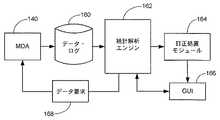
図5は、図4からの各コントローラ/MDAの組み合わせの好適な動作アーキテクチャを示す。以下に更に詳しく説明するように、MDA140における各データ記憶装置100からの動作パラメータのデータは、コントローラ152によりデータ・ログ160内へ累積される。
統計解析エンジン162は、データを解析し、該当する場合は、訂正処置モジュール164を使用してデータ記憶装置特定の訂正処置を開始する。訂正処置モジュール164は、ユーザに対して可視式及び/または可聴式アラーム表示器及び他の出力を提供するためにGUI166(グラフィック・ユーザ・インターフェイス)とインターフェイス接続されている。GUI166により、更に、ユーザ特定のデータ要求及び解析を開始するために、統計解析エンジン162へのアクセスが可能となる。統計解析エンジン162は、更に、要求に応じて、データ・ログ160へ供給されるパラメータ・データの種類及び/またはサンプリング周波数を調整するために、指令ブロック168を介してパラメータ監視データの要求を行う。FIG. 5 shows a preferred operating architecture for each controller / MDA combination from FIG. As described in more detail below, operational parameter data from each
The
データ・ログ160は、MDA140内のデータ記憶装置100により提供される不揮発性のメモリ空間の指定された一部に記憶されることが好ましい。ここからログ全体またはその選択された一部は、統計解析エンジン162によるアクセスを可能にするためにコントローラ152のキャッシュ・メモリ空間へアップロードされる。或いは、(専用アレイを有する)メモリ空間の別個の設備が、データ記憶装置100からのパラメータ・データを記憶するためにコントローラ152によりアクセス可能に設けられる。
データ・ログ160は、与えられたアプリケーションの必要条件に依存して、任意の数の形態をとることができる。特に有用なフォーマットは、図6により一般的に示してあるが、これは、各データ記憶装置100から個々のパラメータ・データを(経過時間のような)共通の指標を使用する別々の「列」で提供する。The
The
従って、例えば、装置1に関する列は、時間に関する履歴シーケンスで単一のパラメータ(例えば、チャネル品質)についてのデータの全てを含むことができ、後で得られるCQ測定値は終わりに添付される。同様なデータは、残りの装置2からNの各々に関する隣接する列で提供される。別々の「シート」は、監視される異なる動作パラメータの各々を追跡するために形成することができる。
しかし、同一のテーブル内へ全てのまたは関連する一部の組の相関パラメータをグループ化し、すなわち各装置当たり異なるシートを提供するフォーマットを備えた、データ・ログ160用の他の構成は容易に考えられる。それでも、データ・ログ160は、MDA140における関連のデータ記憶装置100の全てにわたる履歴のパラメータ・データを表す。Thus, for example, the column for
However, other configurations for the
これにより、垂直データ・ブロック170により示されるデータ記憶装置100の1つと関連したデータに対する統計解析エンジン162による垂直解析の実行、及び、水平データ・ブロック172により示される多数の装置にわたる統計解析エンジン162による水平解析の実行が容易となる。
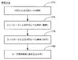
かくして、潜在的な解析モードの階層は、図7に示したように想像される。ある好適な実施例では、個々のデータ記憶装置100は、動作中に選択パラメータの別個の監視を実行するように元々構成されたままで動作を続行する。このことは、ブロック174により表される。この動作は、各装置におけるローカルのトップ・レベル・プロセッサ130(図2)により別個に実施される。This performs a vertical analysis by the
Thus, the hierarchy of potential analysis modes is imagined as shown in FIG. In one preferred embodiment, individual
この例では、特定のパラメータが処理禁止のものであるということがわかると、警報表示をローカルのインターフェイスブロック124を介してMDA入力/出力ブロック142に送ることができ、これはコントローラ152に知らされる。コントローラ152は、このイベントをログに記録するか、または訂正処置モジュール164とGUI166を介してユーザに知らせるような適切な処置をとる。適切な訂正処置は、そのイベントの厳しさに依存し、コントローラによる特定の命令制御入力に応答して装置により、またはユーザの介在により装置レベルで取られてもよい。
上記の動作の他に、個々のデータ記憶装置100により集められ解析されたパラメータ・データの全ては、履歴データをデータ・ログ160に累積するためにデータ・ログ160に送ることが好ましい。In this example, if a particular parameter is found to be prohibited, an alarm indication can be sent to the MDA input /
In addition to the above operations, all of the parameter data collected and analyzed by the individual
図7で提供された解析の他のレベルは、ブロック176で示した、統計解析エンジン162による上記の垂直解析である。個々のデータ記憶装置100が本来の場所でパラメータ解析を続行する上記の例を使用すると、パラメータ解析により別のレベルの検証能力が提供される。すなわち、統計解析エンジン162は、ローカルプロセッサ130と縦列的に同一解析を実行し、システムの信頼性を増し、誤りの存在を減少させることができる。 Another level of analysis provided in FIG. 7 is the vertical analysis described above by the
統計解析エンジン162は、第1のパス・フィルタ・スクリーンとして作用するように、あるいはローカルプロセッサ130に依存することができるので、個々のデータ記憶装置100により設定された警報は、コントローラ・レベルで調査及び解析を開始するために統計解析エンジン162への入力として役立つ。この場合、統計解析エンジン162は、現存のデータに対し高級な統計解析を行い、状況を評価して、障害傾向が実際に検出されたか否か、及び、もし行うとすれば、どんな訂正処置が取られるべきかに関する決定に到達するために、関連するデータ記憶装置100により以前は提供されなかった追加データ(すなわち、より大きなサンプルの周波数、他の利用可能ではあるが通常は報告されないパラメータの報告など)を要求する発見的方法を使用してもよい。 Since the
もう1つの他の実施例では、個々の装置レベルにおけるローカル化されたパラメータの最適化は除去されているが、これは、更に強力な統計解析エンジン162により代わって実行される。この場合、データ記憶装置100は、単に、関連する実行時間のパラメータ・データをデータ・ログ160にアップロードするが、その解析は全然行われないかまたは最小限に限られる。
この特定の試みの利点は、個々の装置の設計及びプログラミングの簡略化である。それは、この解析に要求されるパワーと資源は、設計から除去することができるからである。なお、当業者には、この簡略化により、装置あたりかなりのコスト節減を行うことができ、これに、MDA内に組み込まれた装置の途方もない量を掛算すると、かなりのコスト節減及びシステム利用の進歩をもたらすことができるということが理解されよう。In another alternative embodiment, the optimization of localized parameters at the individual device level has been eliminated, but this is performed on behalf of the more powerful
The advantage of this particular attempt is the simplification of individual device design and programming. This is because the power and resources required for this analysis can be removed from the design. It should be noted that those skilled in the art can achieve significant cost savings per device due to this simplification, which, when multiplied by the tremendous amount of devices incorporated in the MDA, can result in significant cost savings and system utilization. It will be understood that this can lead to progress.
または、その解析側における個々の装置レベルでのシステム資源の解放は、個々の装置がデータ・ログ160へより大きな量のデータ(より多くのサンプル及びより多くの数のパラメータ)を移動するために利用することができる。
従って、この別の試みでは、ブロック176により表される垂直解析は、個々のデータ記憶装置100により行われるローカルのパラメータ解析に置き換わるものと考えられる(ブロック174)。前述のように、コントローラ152の更に大きな処理能力のために、現在利用可能なよりも更に複雑な計算集中的統計処理をデータに対して加えることができる。更に、より多くのデータを得て解析品質を高めるために初期傾向の検出によりブロック168を介して関連するデータ記憶装置100に、適切なデータ要求をもたらすことができる。Alternatively, the release of system resources at the individual device level on the analysis side allows individual devices to move larger amounts of data (more samples and more parameters) to the data log 160. Can be used.
Thus, in this other attempt, the vertical analysis represented by
図7のブロック178は、MDA140における多数のデータ記憶装置100にわたる上記の水平解析を示す。この解析レベルは、例えば、時間ベースまたはパラメータ・ベースでブロック174及び/または176の水平解析の他に行われることが好ましい。なお、ブロック178の水平解析は、履歴ログ160における少なくとも一部のデータの組に対する解析に関わるもので、この一部の組は、MDA140におけるデータ記憶装置100の内の少なくとも複数個に関連している(すなわち、要求に応じてそのアレイにおける複数のデータ記憶装置または全ての装置にわたっている)。
GUI166を介して開始されたユーザ特定の質問及び解析は、ブロック180に示してある。なお、図7における種々のブロックは、単一でまたは組み合わせて利用することができ、その一つの出力は、他の実行の自動的なトリガとすることができる。
User specific questions and analysis initiated via
図8は、解析ブロックを好都合に利用することができる一つの方法を示す。図8は、指標x軸190と共通振幅y軸192に対してグラフでプロットした包括的な一連のパラメータ履歴曲線182、184、186、188を提供する。このパラメータの組のグラフ表示は、関連する処理を実行するために、統計解析エンジン162により必ずしも要求されるものではないが、これらのグラフは本記載を容易にし、所望によりGUI166を介してユーザに容易に提供することができるということが認識されよう。
第1の例では、パラメータ履歴曲線182、184、186、188は、特定のパラメータ、この場合には誤り率にそれぞれ関連した装置1、2、3、Nの各々のデータを表すということが想定される。このデータは、より低い値が「より良い」ものであり、より高い値が「より悪い」ものとなるように表されているが、これは単に一つの利用可能な処方である。関連するベースライン値は、破線により示してある。FIG. 8 illustrates one way in which the analysis block can be advantageously utilized. FIG. 8 provides a comprehensive set of parameter history curves 182, 184, 186, 188 plotted graphically against the
In the first example, it is assumed that the parameter history curves 182, 184, 186, 188 represent data for each of the
(194で局部的に示した)装置Nに対する誤り率におけるかなりの上昇傾向は、傾向解析(移動平均など)によるか、または、関連する閾値(図示せず)の交差により容易に検出することができるということが理解できる。
誤り率の増加は、それ自体必ずしも特定の原因を示唆するものではないが、システムの性能に対する障害傾向の影響を最小にするように影響を受けたデータの再配置のような即時の救済的な訂正処置を取ることを可能にする。しかし、更なる監視及び診断は1つ以上の原因を分離するために行うことができ、これによりシステムからの問題を除去することができる。例示的な訂正処置には、特定のヘッド/メディアの組み合わせの廃棄、MDA内における待機「スペア」の代わりとしての特定の装置の使用、別のRAIDまたはECCレベルの適用、ルーチンの予定保全の実行などが含まれる。A significant upward trend in error rate for device N (shown locally at 194) can be easily detected by trend analysis (such as a moving average) or by crossing associated thresholds (not shown). I understand that I can do it.
An increase in error rate does not necessarily suggest a specific cause per se, but it is an immediate remedy such as the relocation of affected data to minimize the impact of failure trends on system performance. Allows you to take corrective action. However, further monitoring and diagnosis can be performed to isolate one or more causes, thereby eliminating problems from the system. Exemplary corrective actions include discarding a specific head / media combination, using a specific device instead of a standby “spare” in the MDA, applying another RAID or ECC level, performing routine scheduled maintenance Etc. are included.
この例を続行すると、MDA140内における多数の装置にわたるデータの解析により、このイベントに関し更なる重要な情報が提供され、すなわち、装置Nのみが誤り率の局部的増大を現在経験していて、他の装置は明らかに該当する時間期間内において影響を受けないということが知られよう。換言すれば、この点において障害イベントは装置Nに分離されるように見える。 Continuing with this example, analysis of data across multiple devices in
読者は、同一の知識はブロック174の分離した個々の装置レベルの解析に単に頼ることによって利用可能になるように見えるが、事実はそうではなく、禁止条件の傾向を識別するためのアレイ内における他の装置のうちのいずれかの障害は、特定のデータが同時に各装置にとって何であるかを全体的に知ることと同一ではないということを知るであろう。従って、統合されたデータ・ログの試みにより、データ・イベントが単一の装置へ分離される時でも、そして、個々の装置レベルで行われるのと同一レベルの解析が行われる時でも優れた解析及び訂正処置動作が行われる。 The reader appears that the same knowledge can be made available simply by relying on the separate individual device level analysis of
図8を用いて他の例を続行すると、パラメータ履歴曲線182、184、186、188の各々は、例えば、同一または異なる装置に対してそれぞれチャネル品質、サーボ認定時間(servo qualification time)、回転振動及びトラック外れエラーのような種々のパラメータを表すということが考えられる。この場合、それぞれのパラメータの相互依存性への更なる洞察が可能となる196と198でのようなパラメータ間の相関関係を識別することができる。例えば、198における減少が194における対応の増大を誘導するようなタイム・ラグ関係を確立することもできる。この関係を識別すると、特定のイベントの真の原因を更によく分離することができる。 Continuing with the other example using FIG. 8, each of the parameter history curves 182, 184, 186, 188 is, for example, channel quality, servo qualification time, rotational vibration, respectively, for the same or different devices. And may represent various parameters such as an out of track error. In this case, correlations between parameters can be identified, such as at 196 and 198, which allow further insight into the interdependencies of the respective parameters. For example, a time lag relationship may be established such that a decrease in 198 induces a corresponding increase in 194. Identifying this relationship can better isolate the true cause of a particular event.
例えば、パラメータ履歴曲線184に関連した装置(装置2)は、パラメータ履歴曲線186により示される装置(装置3)に作用することでパラメータ履歴曲線188(装置N)にエラーを誘導するということを決定してもよい。従って、装置2の調整または置換により、装置3とNなどにより経験される動作上の難点が解決されよう。
今や、本明細書に示した本発明の好適な実施例は、従来技術に比較して利点を提供するということが理解されよう。いくつものデータ記憶装置100にわたり履歴データを累算するデータ・ログ160を使用することによりコスト節減とシステム資源の解放、装置単位でのパラメータ・データのより深い大規模な解析、及び多数の装置にわたるデータの解析を行うことができる。For example, the device associated with the parameter history curve 184 (device 2) determines that acting on the device (device 3) indicated by the
It will now be appreciated that the preferred embodiment of the present invention presented herein provides advantages over the prior art. Use of a
添付の請求項のために述べれば、列挙した第1の手段は、図5で示したコントローラの構造に対応するものと理解され、統計解析エンジンは、図6と図7に示した水平解析を実施するように構成されている。
なお、本発明の種々の実施例の数多くの特徴及び利点は、本発明の種々の実施例の構造及び機能の詳細と共に上記記載で示されたが、この詳細な記載は、単に例示的なものであって、種々の変更は、詳細に、特に、添付の請求項を表現する用語の広い一般的な意味により示される十分な程度まで本発明の原理内における部品の構成及び配置の点でなし得ようということは理解されるべきである。例えば、特定の要素は、本発明の主旨及び範囲から逸脱せずに特定の制御環境に依存して変化してもよい。For the purposes of the appended claims, it is understood that the listed first means correspond to the structure of the controller shown in FIG. 5, and the statistical analysis engine performs the horizontal analysis shown in FIGS. It is configured to be implemented.
Although numerous features and advantages of various embodiments of the invention have been presented above, together with details of the structure and function of the various embodiments of the invention, this detailed description is merely illustrative. However, various modifications may be made in detail, particularly in terms of the arrangement and arrangement of components within the principles of the present invention to the full extent indicated by the broad general meaning of the terms expressing the appended claims. It is to be understood that you will get. For example, the particular elements may vary depending on the particular control environment without departing from the spirit and scope of the present invention.
更に、ここに記載した実施例は、共通のアドレス可能なメモリ空間を提供するためのいくつものハード・ディスク・ドライブを使用するマルチ・ディスク・アレイに関するものであるが、当業者は、請求の主題はそのように制限されるものではなく、光ベースの固体データ記憶装置を含む種々の他のデータ記憶システムが請求になる本発明の主旨及び範囲から逸脱せずに容易に利用することができるということを理解するであろう。 Further, although the embodiments described herein relate to multi-disk arrays that use a number of hard disk drives to provide a common addressable memory space, those skilled in the art will Is not so limited, and various other data storage systems, including light-based solid state data storage devices, can be readily utilized without departing from the spirit and scope of the claimed invention. You will understand that.
100 データ記憶装置
102 ハウジング
104 基部デッキ
106 上カバー
108 スピンドル・モータ
110 メディア
112 データ変換ヘッド
114 アクチュエータ
116 音声コイル・モータVCM
118 フレックス回路アセンブリ
120 プリント回路板PCB
130 プリアンプDESCRIPTION OF
118
130 Preamplifier
Claims (20)
Translated fromJapanese前記コントローラは、チャネル品質、サーボ認定時間、回転振動、およびトラック外れエラーを含む複数のパラメータ間の相関関係を識別することで、前記データ記憶装置の動作性能データを解析する、装置。A plurality of data storage devices configured to form a multi-device memory array space; and a controller for controlling access to the multi-device memory array space, the controller comprising: A set of operational performance data from multiple data storage devices is used as an index into a single data log, and a plurality of indexes are used to indicate a vertical block of data in a single data log associated with one of the data storage devices, by analyzing at least one of the horizontal block of data in a single data log associated with the data storage deviceis configured to detect defects trends of one or more data storagedevices,
The apparatus, wherein the controller analyzes operational performance data of the data storage device by identifying a correlation between a plurality of parameters including channel quality, servo qualification time, rotational vibration, and off-track error .
前記複数のデータ記憶装置からの動作性能データの組を指標とし、前記指標とされたデータの一部ブロックの解析を行なうことによって、1以上のデータ蓄積装置の欠陥動向を検出する第1の手段とを備え、
前記第1の手段は、チャネル品質、サーボ認定時間、回転振動、およびトラック外れエラーを含む複数のパラメータ間の相関関係を識別することで、前記データ記憶装置の動作性能データを解析する、装置。A plurality of data storage devices configured to form a multi-device memory array space;
First means for detecting a defect trend of one or more data storage devices by using a set of operation performance data from the plurality of data storage devices as an index and analyzing a partial block of the indexed datafor example Bei thedoor,
The apparatus wherein the first means analyzes operational performance data of the data storage device by identifying a correlation between a plurality of parameters including channel quality, servo qualification time, rotational vibration, and off-track error .
前記複数のデータ記憶装置からの動作性能データの組を単一データログ内への指標とするステップと、
複数の指標でデータ記憶装置の1つと関連する単一データログにおけるデータの垂直ブロックと、1つの指標で複数のデータ記憶装置と関連する単一データログにおけるデータの水平ブロックとの少なくとも一方を解析することによって、1以上のデータ蓄積装置の欠陥動向を検出するステップとを有し、
前記欠陥動向を検出するステップは、チャネル品質、サーボ認定時間、回転振動、およびトラック外れエラーを含む複数のパラメータ間の相関関係を識別することで、前記データ記憶装置の動作性能データを解析するステップを含む、方法。Arranging a plurality of data storage devices to form a multi-device memory array space;
Using a set of operational performance data from the plurality of data storage devices as an index into a single data log;
Analyzing at least one of a vertical block of data in a single data log associated with one of the data storage devices with multiple indicators and a horizontal block of data in a single data log associated with multiple data storage devices with one indicator by,it possesses and detecting a defect trends of one or more data storagedevices,
The step of detecting the defect trend is a step of analyzing operation performance data of the data storage device by identifying a correlation between a plurality of parameters including channel quality, servo qualification time, rotational vibration, and off-track error. Including a method.
Applications Claiming Priority (2)
| Application Number | Priority Date | Filing Date | Title |
|---|---|---|---|
| US11/070942 | 2005-03-03 | ||
| US11/070,942US20060200726A1 (en) | 2005-03-03 | 2005-03-03 | Failure trend detection and correction in a data storage array |
Publications (2)
| Publication Number | Publication Date |
|---|---|
| JP2006244447A JP2006244447A (en) | 2006-09-14 |
| JP5059304B2true JP5059304B2 (en) | 2012-10-24 |
Family
ID=36945437
Family Applications (1)
| Application Number | Title | Priority Date | Filing Date |
|---|---|---|---|
| JP2005202408AExpired - Fee RelatedJP5059304B2 (en) | 2005-03-03 | 2005-07-12 | Apparatus and method for detecting and correcting failure trends in data storage arrays |
Country Status (2)
| Country | Link |
|---|---|
| US (2) | US20060200726A1 (en) |
| JP (1) | JP5059304B2 (en) |
Families Citing this family (32)
| Publication number | Priority date | Publication date | Assignee | Title |
|---|---|---|---|---|
| US7636872B2 (en)* | 2005-03-23 | 2009-12-22 | Microsoft Corporation | Threat event-driven backup |
| US7747907B2 (en)* | 2005-09-20 | 2010-06-29 | Seagate Technology Llc | Preventive recovery from adjacent track interference |
| US8271140B2 (en)* | 2006-08-25 | 2012-09-18 | International Business Machines Corporation | Periodic rotational vibration check for storage devices to compensate for varying loads |
| US8319613B2 (en)* | 2009-02-09 | 2012-11-27 | Steven Lazar | Smart cap with communication function |
| US8683456B2 (en)* | 2009-07-13 | 2014-03-25 | Apple Inc. | Test partitioning for a non-volatile memory |
| JP5468837B2 (en)* | 2009-07-30 | 2014-04-09 | 株式会社日立製作所 | Anomaly detection method, apparatus, and program |
| EP2523115B1 (en) | 2010-01-08 | 2020-05-06 | Nec Corporation | Operation management device, operation management method, and program storage medium |
| US8650446B2 (en)* | 2010-03-24 | 2014-02-11 | Apple Inc. | Management of a non-volatile memory based on test quality |
| US8645776B2 (en)* | 2010-03-24 | 2014-02-04 | Apple Inc. | Run-time testing of memory locations in a non-volatile memory |
| US8751903B2 (en) | 2010-07-26 | 2014-06-10 | Apple Inc. | Methods and systems for monitoring write operations of non-volatile memory |
| US8726095B2 (en) | 2010-12-02 | 2014-05-13 | Dell Products L.P. | System and method for proactive management of an information handling system with in-situ measurement of end user actions |
| US8707111B2 (en)* | 2011-02-09 | 2014-04-22 | Ebay Inc. | High-volume distributed script error handling |
| WO2014006701A1 (en)* | 2012-07-04 | 2014-01-09 | 富士通株式会社 | Information processing device, access control program, and access control method |
| US8970977B1 (en)* | 2012-09-28 | 2015-03-03 | Western Digital Technologies, Inc. | Disk drive logging failure analysis data when performing an emergency unload |
| US9720716B2 (en)* | 2013-03-12 | 2017-08-01 | Intel Corporation | Layered virtual machine integrity monitoring |
| US8908308B1 (en) | 2013-11-26 | 2014-12-09 | Seagate Technology Llc | Adaptive passive data track erasure healing |
| US10514978B1 (en) | 2015-10-23 | 2019-12-24 | Pure Storage, Inc. | Automatic deployment of corrective measures for storage arrays |
| US9384082B1 (en)* | 2015-10-23 | 2016-07-05 | Pure Storage, Inc. | Proactively providing corrective measures for storage arrays |
| US11360844B1 (en) | 2015-10-23 | 2022-06-14 | Pure Storage, Inc. | Recovery of a container storage provider |
| US10247565B2 (en) | 2016-04-11 | 2019-04-02 | State Farm Mutual Automobile Insurance Company | Traffic risk avoidance for a route selection system |
| US10233679B1 (en) | 2016-04-11 | 2019-03-19 | State Farm Mutual Automobile Insurance Company | Systems and methods for control systems to facilitate situational awareness of a vehicle |
| US10019904B1 (en) | 2016-04-11 | 2018-07-10 | State Farm Mutual Automobile Insurance Company | System for identifying high risk parking lots |
| US11851041B1 (en) | 2016-04-11 | 2023-12-26 | State Farm Mutual Automobile Insurance Company | System for determining road slipperiness in bad weather conditions |
| US10486708B1 (en) | 2016-04-11 | 2019-11-26 | State Farm Mutual Automobile Insurance Company | System for adjusting autonomous vehicle driving behavior to mimic that of neighboring/surrounding vehicles |
| US10222228B1 (en) | 2016-04-11 | 2019-03-05 | State Farm Mutual Automobile Insurance Company | System for driver's education |
| US10026309B1 (en) | 2016-04-11 | 2018-07-17 | State Farm Mutual Automobile Insurance Company | Networked vehicle control systems to facilitate situational awareness of vehicles |
| US10872379B1 (en) | 2016-04-11 | 2020-12-22 | State Farm Mutual Automobile Insurance Company | Collision risk-based engagement and disengagement of autonomous control of a vehicle |
| US11099924B2 (en) | 2016-08-02 | 2021-08-24 | International Business Machines Corporation | Preventative system issue resolution |
| US10621026B2 (en)* | 2017-06-04 | 2020-04-14 | Apple Inc. | Auto bug capture |
| US11237893B2 (en) | 2019-06-26 | 2022-02-01 | Western Digital Technologies, Inc. | Use of error correction-based metric for identifying poorly performing data storage devices |
| US10969969B2 (en) | 2019-06-26 | 2021-04-06 | Western Digital Technologies, Inc. | Use of recovery behavior for prognosticating and in-situ repair of data storage devices |
| US11150971B1 (en) | 2020-04-07 | 2021-10-19 | International Business Machines Corporation | Pattern recognition for proactive treatment of non-contiguous growing defects |
Family Cites Families (28)
| Publication number | Priority date | Publication date | Assignee | Title |
|---|---|---|---|---|
| US624890A (en)* | 1899-05-09 | Valve-controlling device | ||
| US5450609A (en)* | 1990-11-13 | 1995-09-12 | Compaq Computer Corp. | Drive array performance monitor |
| JPH0651915A (en)* | 1992-08-03 | 1994-02-25 | Hitachi Ltd | Disk device and disk array control system |
| US5774285A (en)* | 1995-09-06 | 1998-06-30 | Seagate Technology, Inc. | Selection of optimal read/write channel parameters in a hard disc drive |
| US5721816A (en)* | 1996-07-29 | 1998-02-24 | Kusbel; Paul F. | Adaptive recovery of read and write errors in a disc drive |
| JPH11345095A (en)* | 1998-06-02 | 1999-12-14 | Toshiba Corp | Disk array device and control method therefor |
| US6249890B1 (en)* | 1998-06-05 | 2001-06-19 | Seagate Technology Llc | Detecting head readback response degradation in a disc drive |
| US6980381B2 (en)* | 1998-09-21 | 2005-12-27 | William F. Gray | Apparatus and method for predicting failure of a disk drive |
| US6401214B1 (en)* | 1999-03-04 | 2002-06-04 | International Business Machines Corporation | Preventive recovery action in hard disk drives |
| JP2000305720A (en)* | 1999-04-15 | 2000-11-02 | Nec Software Hokkaido Ltd | Method for automatically resorting array disk and system therefor |
| US6606210B1 (en)* | 1999-04-21 | 2003-08-12 | Seagate Technology Llc | Intelligent sector recovery algorithm |
| US6738757B1 (en)* | 1999-06-02 | 2004-05-18 | Workwise, Inc. | System for database monitoring and agent implementation |
| US6832236B1 (en)* | 1999-07-08 | 2004-12-14 | International Business Machines Corporation | Method and system for implementing automatic filesystem growth monitor for production UNIX computer system |
| US6415189B1 (en)* | 1999-07-23 | 2002-07-02 | International Business Machines Corporation | Method and system for predicting disk drive failures |
| US6460151B1 (en)* | 1999-07-26 | 2002-10-01 | Microsoft Corporation | System and method for predicting storage device failures |
| US6611393B1 (en)* | 2001-04-30 | 2003-08-26 | Western Digital Technologies, Inc. | Disk drive employing field calibration based on marginal sectors |
| US6760174B2 (en)* | 2001-08-06 | 2004-07-06 | Seagate Technology Llc | Adaptive fly height for error recovery in a disc drive |
| US6771440B2 (en)* | 2001-12-18 | 2004-08-03 | International Business Machines Corporation | Adaptive event-based predictive failure analysis measurements in a hard disk drive |
| US7293003B2 (en)* | 2002-03-21 | 2007-11-06 | Sun Microsystems, Inc. | System and method for ranking objects by likelihood of possessing a property |
| US6732233B2 (en)* | 2002-05-21 | 2004-05-04 | International Business Machines Corporation | Hot spare reliability for storage arrays and storage networks |
| US6982842B2 (en)* | 2002-09-16 | 2006-01-03 | Seagate Technology Llc | Predictive disc drive failure methodology |
| US6892276B2 (en)* | 2002-11-26 | 2005-05-10 | Lsi Logic Corporation | Increased data availability in raid arrays using smart drives |
| JP2004227449A (en)* | 2003-01-27 | 2004-08-12 | Hitachi Ltd | Diagnosis device for failure in disk array device |
| US7317943B2 (en)* | 2003-01-31 | 2008-01-08 | Medtronic, Inc. | Capture threshold monitoring |
| US7373559B2 (en)* | 2003-09-11 | 2008-05-13 | Copan Systems, Inc. | Method and system for proactive drive replacement for high availability storage systems |
| US20080256397A1 (en)* | 2004-09-22 | 2008-10-16 | Xyratex Technology Limited | System and Method for Network Performance Monitoring and Predictive Failure Analysis |
| US7769975B2 (en)* | 2004-11-15 | 2010-08-03 | International Business Machines Corporation | Method for configuring volumes in a storage system |
| US20070079170A1 (en)* | 2005-09-30 | 2007-04-05 | Zimmer Vincent J | Data migration in response to predicted disk failure |
- 2005
- 2005-03-03USUS11/070,942patent/US20060200726A1/ennot_activeAbandoned
- 2005-07-12JPJP2005202408Apatent/JP5059304B2/ennot_activeExpired - Fee Related
- 2007
- 2007-10-04USUS11/867,543patent/US7765437B2/ennot_activeExpired - Lifetime
Also Published As
| Publication number | Publication date |
|---|---|
| US20080244316A1 (en) | 2008-10-02 |
| JP2006244447A (en) | 2006-09-14 |
| US20060200726A1 (en) | 2006-09-07 |
| US7765437B2 (en) | 2010-07-27 |
Similar Documents
| Publication | Publication Date | Title |
|---|---|---|
| JP5059304B2 (en) | Apparatus and method for detecting and correcting failure trends in data storage arrays | |
| US7526684B2 (en) | Deterministic preventive recovery from a predicted failure in a distributed storage system | |
| US6600614B2 (en) | Critical event log for a disc drive | |
| US7908526B2 (en) | Method and system for proactive drive replacement for high availability storage systems | |
| US10606722B2 (en) | Method and system for diagnosing remaining lifetime of storages in data center | |
| CN101131855B (en) | Method and system for monitoring rotary vibration | |
| US20180060192A1 (en) | Adaptive Failure Prediction Modeling for Detection of Data Storage Device Failures | |
| JP2005293594A (en) | Managed reliability storage system and method | |
| JP2005322399A (en) | Method for maintaining track data integrity in a magnetic disk storage device | |
| CN113179665B (en) | Using error correction based metrics to identify poor performing data storage devices | |
| Huang et al. | Characterizing disk health degradation and proactively protecting against disk failures for reliable storage systems | |
| CN113179657B (en) | Use of recovery behavior for prognosis and in-situ repair of data storage devices | |
| US7359134B2 (en) | Data save processing method for disk storage device and disk storage system | |
| US7457990B2 (en) | Information processing apparatus and information processing recovery method | |
| JP6079578B2 (en) | Storage control device, storage control program, and storage control method | |
| US10748582B1 (en) | Data storage device with recording surface resolution | |
| JP2019053486A (en) | Malfunction sign detecting device, malfunction sign detecting method, and, malfunction sign detecting program | |
| JP2003263703A5 (en) | ||
| JP2007048017A (en) | Storage system and storage control method | |
| JP7662198B2 (en) | Storage medium management device, storage medium management method, and storage medium management program | |
| CN109800134A (en) | A kind of method and system of the remaining life of diagnostic data central storage equipment | |
| CN117746924A (en) | Fault diagnosis method, disk device manufacturing method, and recording medium | |
| EP3486779A1 (en) | Method and system for diagnosing remaining lifetime of storages in data center | |
| HK40009917A (en) | Method and system for diagnosing remaining lifetime of storages in data center | |
| JP2025139173A (en) | Prediction system, prediction method, and program |
Legal Events
| Date | Code | Title | Description |
|---|---|---|---|
| A621 | Written request for application examination | Free format text:JAPANESE INTERMEDIATE CODE: A621 Effective date:20080709 | |
| RD03 | Notification of appointment of power of attorney | Free format text:JAPANESE INTERMEDIATE CODE: A7423 Effective date:20100526 | |
| A977 | Report on retrieval | Free format text:JAPANESE INTERMEDIATE CODE: A971007 Effective date:20101203 | |
| A131 | Notification of reasons for refusal | Free format text:JAPANESE INTERMEDIATE CODE: A131 Effective date:20101214 | |
| A131 | Notification of reasons for refusal | Free format text:JAPANESE INTERMEDIATE CODE: A131 Effective date:20111122 | |
| A601 | Written request for extension of time | Free format text:JAPANESE INTERMEDIATE CODE: A601 Effective date:20120221 | |
| A602 | Written permission of extension of time | Free format text:JAPANESE INTERMEDIATE CODE: A602 Effective date:20120224 | |
| A521 | Request for written amendment filed | Free format text:JAPANESE INTERMEDIATE CODE: A523 Effective date:20120321 | |
| TRDD | Decision of grant or rejection written | ||
| A01 | Written decision to grant a patent or to grant a registration (utility model) | Free format text:JAPANESE INTERMEDIATE CODE: A01 Effective date:20120731 | |
| A01 | Written decision to grant a patent or to grant a registration (utility model) | Free format text:JAPANESE INTERMEDIATE CODE: A01 | |
| A61 | First payment of annual fees (during grant procedure) | Free format text:JAPANESE INTERMEDIATE CODE: A61 Effective date:20120802 | |
| FPAY | Renewal fee payment (event date is renewal date of database) | Free format text:PAYMENT UNTIL: 20150810 Year of fee payment:3 | |
| R150 | Certificate of patent or registration of utility model | Free format text:JAPANESE INTERMEDIATE CODE: R150 | |
| LAPS | Cancellation because of no payment of annual fees |