JP5059301B2 - Synchronous playback apparatus and synchronous playback method - Google Patents
Synchronous playback apparatus and synchronous playback methodDownload PDFInfo
- Publication number
- JP5059301B2 JP5059301B2JP2005163147AJP2005163147AJP5059301B2JP 5059301 B2JP5059301 B2JP 5059301B2JP 2005163147 AJP2005163147 AJP 2005163147AJP 2005163147 AJP2005163147 AJP 2005163147AJP 5059301 B2JP5059301 B2JP 5059301B2
- Authority
- JP
- Japan
- Prior art keywords
- audio
- video
- data
- signal
- amount
- Prior art date
- Legal status (The legal status is an assumption and is not a legal conclusion. Google has not performed a legal analysis and makes no representation as to the accuracy of the status listed.)
- Expired - Fee Related
Links
Images


Classifications
- H—ELECTRICITY
- H04—ELECTRIC COMMUNICATION TECHNIQUE
- H04N—PICTORIAL COMMUNICATION, e.g. TELEVISION
- H04N21/00—Selective content distribution, e.g. interactive television or video on demand [VOD]
- H04N21/20—Servers specifically adapted for the distribution of content, e.g. VOD servers; Operations thereof
- H04N21/23—Processing of content or additional data; Elementary server operations; Server middleware
- H04N21/236—Assembling of a multiplex stream, e.g. transport stream, by combining a video stream with other content or additional data, e.g. inserting a URL [Uniform Resource Locator] into a video stream, multiplexing software data into a video stream; Remultiplexing of multiplex streams; Insertion of stuffing bits into the multiplex stream, e.g. to obtain a constant bit-rate; Assembling of a packetised elementary stream
- H04N21/2368—Multiplexing of audio and video streams
- G—PHYSICS
- G11—INFORMATION STORAGE
- G11B—INFORMATION STORAGE BASED ON RELATIVE MOVEMENT BETWEEN RECORD CARRIER AND TRANSDUCER
- G11B20/00—Signal processing not specific to the method of recording or reproducing; Circuits therefor
- G11B20/10—Digital recording or reproducing
- G11B20/10527—Audio or video recording; Data buffering arrangements
- G—PHYSICS
- G11—INFORMATION STORAGE
- G11B—INFORMATION STORAGE BASED ON RELATIVE MOVEMENT BETWEEN RECORD CARRIER AND TRANSDUCER
- G11B27/00—Editing; Indexing; Addressing; Timing or synchronising; Monitoring; Measuring tape travel
- G11B27/10—Indexing; Addressing; Timing or synchronising; Measuring tape travel
- H—ELECTRICITY
- H04—ELECTRIC COMMUNICATION TECHNIQUE
- H04N—PICTORIAL COMMUNICATION, e.g. TELEVISION
- H04N21/00—Selective content distribution, e.g. interactive television or video on demand [VOD]
- H04N21/40—Client devices specifically adapted for the reception of or interaction with content, e.g. set-top-box [STB]; Operations thereof
- H04N21/43—Processing of content or additional data, e.g. demultiplexing additional data from a digital video stream; Elementary client operations, e.g. monitoring of home network or synchronising decoder's clock; Client middleware
- H04N21/4302—Content synchronisation processes, e.g. decoder synchronisation
- H04N21/4307—Synchronising the rendering of multiple content streams or additional data on devices, e.g. synchronisation of audio on a mobile phone with the video output on the TV screen
- H04N21/43072—Synchronising the rendering of multiple content streams or additional data on devices, e.g. synchronisation of audio on a mobile phone with the video output on the TV screen of multiple content streams on the same device
- H—ELECTRICITY
- H04—ELECTRIC COMMUNICATION TECHNIQUE
- H04N—PICTORIAL COMMUNICATION, e.g. TELEVISION
- H04N21/00—Selective content distribution, e.g. interactive television or video on demand [VOD]
- H04N21/40—Client devices specifically adapted for the reception of or interaction with content, e.g. set-top-box [STB]; Operations thereof
- H04N21/43—Processing of content or additional data, e.g. demultiplexing additional data from a digital video stream; Elementary client operations, e.g. monitoring of home network or synchronising decoder's clock; Client middleware
- H04N21/434—Disassembling of a multiplex stream, e.g. demultiplexing audio and video streams, extraction of additional data from a video stream; Remultiplexing of multiplex streams; Extraction or processing of SI; Disassembling of packetised elementary stream
- H04N21/4341—Demultiplexing of audio and video streams
- H—ELECTRICITY
- H04—ELECTRIC COMMUNICATION TECHNIQUE
- H04N—PICTORIAL COMMUNICATION, e.g. TELEVISION
- H04N5/00—Details of television systems
- H04N5/76—Television signal recording
- G—PHYSICS
- G11—INFORMATION STORAGE
- G11B—INFORMATION STORAGE BASED ON RELATIVE MOVEMENT BETWEEN RECORD CARRIER AND TRANSDUCER
- G11B20/00—Signal processing not specific to the method of recording or reproducing; Circuits therefor
- G11B20/10—Digital recording or reproducing
- G11B20/10527—Audio or video recording; Data buffering arrangements
- G11B2020/1062—Data buffering arrangements, e.g. recording or playback buffers
- G11B2020/10629—Data buffering arrangements, e.g. recording or playback buffers the buffer having a specific structure
- G11B2020/10638—First-in-first-out memories [FIFO] buffers
- G—PHYSICS
- G11—INFORMATION STORAGE
- G11B—INFORMATION STORAGE BASED ON RELATIVE MOVEMENT BETWEEN RECORD CARRIER AND TRANSDUCER
- G11B20/00—Signal processing not specific to the method of recording or reproducing; Circuits therefor
- G11B20/10—Digital recording or reproducing
- G11B20/10527—Audio or video recording; Data buffering arrangements
- G11B2020/1062—Data buffering arrangements, e.g. recording or playback buffers
- G11B2020/10675—Data buffering arrangements, e.g. recording or playback buffers aspects of buffer control
- G11B2020/10694—Data buffering arrangements, e.g. recording or playback buffers aspects of buffer control output interface, i.e. the way data leave the buffer, e.g. by adjusting the clock rate
- H—ELECTRICITY
- H04—ELECTRIC COMMUNICATION TECHNIQUE
- H04N—PICTORIAL COMMUNICATION, e.g. TELEVISION
- H04N5/00—Details of television systems
- H04N5/04—Synchronising
- H—ELECTRICITY
- H04—ELECTRIC COMMUNICATION TECHNIQUE
- H04N—PICTORIAL COMMUNICATION, e.g. TELEVISION
- H04N9/00—Details of colour television systems
- H04N9/79—Processing of colour television signals in connection with recording
- H04N9/80—Transformation of the television signal for recording, e.g. modulation, frequency changing; Inverse transformation for playback
- H04N9/804—Transformation of the television signal for recording, e.g. modulation, frequency changing; Inverse transformation for playback involving pulse code modulation of the colour picture signal components
- H04N9/8042—Transformation of the television signal for recording, e.g. modulation, frequency changing; Inverse transformation for playback involving pulse code modulation of the colour picture signal components involving data reduction
- H—ELECTRICITY
- H04—ELECTRIC COMMUNICATION TECHNIQUE
- H04N—PICTORIAL COMMUNICATION, e.g. TELEVISION
- H04N9/00—Details of colour television systems
- H04N9/79—Processing of colour television signals in connection with recording
- H04N9/80—Transformation of the television signal for recording, e.g. modulation, frequency changing; Inverse transformation for playback
- H04N9/804—Transformation of the television signal for recording, e.g. modulation, frequency changing; Inverse transformation for playback involving pulse code modulation of the colour picture signal components
- H04N9/806—Transformation of the television signal for recording, e.g. modulation, frequency changing; Inverse transformation for playback involving pulse code modulation of the colour picture signal components with processing of the sound signal
- H04N9/8063—Transformation of the television signal for recording, e.g. modulation, frequency changing; Inverse transformation for playback involving pulse code modulation of the colour picture signal components with processing of the sound signal using time division multiplex of the PCM audio and PCM video signals
- H—ELECTRICITY
- H04—ELECTRIC COMMUNICATION TECHNIQUE
- H04N—PICTORIAL COMMUNICATION, e.g. TELEVISION
- H04N9/00—Details of colour television systems
- H04N9/79—Processing of colour television signals in connection with recording
- H04N9/80—Transformation of the television signal for recording, e.g. modulation, frequency changing; Inverse transformation for playback
- H04N9/82—Transformation of the television signal for recording, e.g. modulation, frequency changing; Inverse transformation for playback the individual colour picture signal components being recorded simultaneously only
- H04N9/8205—Transformation of the television signal for recording, e.g. modulation, frequency changing; Inverse transformation for playback the individual colour picture signal components being recorded simultaneously only involving the multiplexing of an additional signal and the colour video signal
Landscapes
- Engineering & Computer Science (AREA)
- Multimedia (AREA)
- Signal Processing (AREA)
- Television Signal Processing For Recording (AREA)
- Two-Way Televisions, Distribution Of Moving Picture Or The Like (AREA)
- Signal Processing For Digital Recording And Reproducing (AREA)
- Compression Or Coding Systems Of Tv Signals (AREA)
Description
Translated fromJapanese本発明は、ビデオデータ及びオーディオデータの同期再生装置及び同期再生方法に関し、特に複数のオーディオデータを含むデータのオーディオデータとビデオデータの同期再生に関する。 The present invention relates to a synchronized playback apparatus and synchronized playback method for video data and audio data, and more particularly to synchronized playback of audio data and video data of data including a plurality of audio data.
ビデオデータおよびオーディオデータの符号化、およびこれらのデータの多重化に関する国際規格として、MPEG(Moving Picture Expert Group)規格が広く知られている。MPEG規格に基づいて記録されたビデオデータ、オーディオデータにはPTS(Presentation Time Stamp)と呼ばれる時間同期を取るための情報が付加されている。例えば、ビデオデータに対応して複数のオーディオデータを持つようなストリームの場合、このPTSにより映像を再生したまま音声のみを切り替えることが出来る。 The MPEG (Moving Picture Expert Group) standard is widely known as an international standard for encoding video data and audio data and multiplexing the data. Information for obtaining time synchronization called PTS (Presentation Time Stamp) is added to video data and audio data recorded based on the MPEG standard. For example, in the case of a stream having a plurality of audio data corresponding to video data, it is possible to switch only the sound while reproducing the video by this PTS.
MPEG方式により記録された映像/音声の再生装置の普及に伴い、映像/音声をMPEG方式で記録する装置やパーソナルコンピュータを用いて記録を行うソフトウェアも普及している。しかしこれらの中にはMPEGの規格を独自に解釈したため、このPTSを含まないMPEGストリームを作成するものがある。このPTSを含まないMPEGストリームでは、映像と音声の同期を取るために映像と音声を共に停止した後に音声を切り替えて再生を再開しなければならない。 Accompanying the widespread use of video / audio playback devices recorded by the MPEG method, devices for recording video / audio by the MPEG method and software for recording using a personal computer have also become popular. However, some of them create an MPEG stream that does not include the PTS because the MPEG standard is uniquely interpreted. In the MPEG stream that does not include the PTS, in order to synchronize the video and the audio, both the video and the audio must be stopped and then the audio must be switched to resume the reproduction.
そこで、このようなMPEGストリームで同期を取る技術として特許文献1に記載された技術がある。特許文献1に記載の技術では、オーディオデータは常に一定間隔で挿入されることを前提としており、この前提と記録媒体であるCDの特性を利用してオーディオデータの仮想PTSを計算している。さらに、この仮想のPTSとビデオデータに付随するPTSの同期を取ることで、ビデオデータとオーディオデータの同期を行っている。
しかしながら、特許文献1に記載の技術では、オーディオデータの仮想のPTSを求めるために記録媒体の特性を利用しなければならなかった。 However, in the technique described in
本発明の実施態様に関わる同期再生装置は、ビデオデータ、オーディオデータを重畳した信号から映像信号、音声信号をそれぞれ出力する同期再生装置であって、ビデオデータ及びオーディオデータを分離するデータ分離部と、データ分離部により分離されたビデオデータを一時保持するビデオバッファと、データ分離部により分離されたオーディオデータを一時保持するオーディオバッファと、ビデオバッファに一時保持されたビデオデータをデコードし、映像信号を出力するビデオデコーダと、オーディオバッファに一時保持されたオーディオデータをデコードし、映像信号を出力するオーディオデコーダと、ビデオバッファに蓄積されているビデオデータの量を取得し、蓄積量信号を出力するビデオバッファ蓄積量取得部と、ビデオデコーダがデコードするビデオデータのビットレートを取得し、ビットレート信号を出力するビットレート取得部と、蓄積量信号およびビットレート信号に基づいてオーディオデコーダの出力する音声信号のタイミングを決定する同期制御部とを有する。 A synchronous playback apparatus according to an embodiment of the present invention is a synchronous playback apparatus that outputs a video signal and an audio signal from a signal on which video data and audio data are superimposed, and a data separation unit that separates video data and audio data; A video buffer that temporarily holds the video data separated by the data separation unit, an audio buffer that temporarily holds the audio data separated by the data separation unit, and a video signal that is temporarily held in the video buffer; The video decoder that outputs the video data, the audio data temporarily stored in the audio buffer, the audio decoder that outputs the video signal, the amount of video data stored in the video buffer is obtained, and the accumulated amount signal is output. Video buffer storage acquisition unit and video The bit rate acquisition unit that acquires the bit rate of the video data decoded by the decoder and outputs the bit rate signal, and the synchronization control that determines the timing of the audio signal output from the audio decoder based on the accumulation amount signal and the bit rate signal Part.
また、本発明の実施態様に関わる同期再生方法は、ビデオデータ、オーディオデータを重畳した信号から映像信号、音声信号をそれぞれ再生する同期再生方法であって、ビデオデータ及びオーディオデータを分離し、データ分離部により分離されたビデオデータを一時保持し、データ分離部により分離されたオーディオデータを一時保持し、一時保持されているビデオデータの量を取得し、ビデオデータをデコードするビットレートを取得し、一時保持されているビデオデータの量およびビットレートに基づいてオーディオデータをデコードして音声信号を出力するタイミングを決定する。 The synchronized playback method according to the embodiment of the present invention is a synchronized playback method for reproducing a video signal and an audio signal from a signal on which video data and audio data are superimposed. The video data separated by the separation unit is temporarily held, the audio data separated by the data separation unit is temporarily held, the amount of video data temporarily held is obtained, and the bit rate for decoding the video data is obtained. The audio data is decoded based on the amount of video data temporarily held and the bit rate, and the timing for outputting the audio signal is determined.
記録媒体によらず、PTSがオーディオデータに付随しないMPEGストリームであっても映像と音声を同期させた再生が可能である。 Regardless of the recording medium, even if the PTS is an MPEG stream that does not accompany audio data, playback in which video and audio are synchronized is possible.
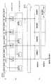
図1は、本発明の実施の形態に関わる同期再生装置のブロック図を示す。この実施の形態の同期再生装置は、MPEG2などの規格に基づいたストリームを受け取り、その映像信号と音声信号を同期させて再生するものである。 FIG. 1 shows a block diagram of a synchronized playback apparatus according to an embodiment of the present invention. The synchronous reproduction apparatus of this embodiment receives a stream based on a standard such as MPEG2 and reproduces the video signal and the audio signal in synchronization.
図1に示す同期再生装置は、基本的な再生装置の構成としてデマルチプレクサ10、ビデオバッファ11、ビデオデコーダ12、オーディオバッファ13、オーディオデコーダ14、システムデコーダ15を有している。本実施の形態の同期再生装置はさらに、ビデオバッファ蓄積量取得部21、ビットレート取得部22、PTS検出部23、同期制御部24、出力遅延制御部25を有している。 The synchronous playback apparatus shown in FIG. 1 has a demultiplexer 10, a video buffer 11, a
デマルチプレクサ10は、入力されるMPEGストリームを分離し、ビデオデータ、オーディオデータ、再生情報として出力する分離装置である。 The demultiplexer 10 is a separation device that separates an input MPEG stream and outputs it as video data, audio data, and reproduction information.
ビデオバッファ11は、デマルチプレクサから出力されたビデオデータを一時保持するバッファである。この実施の形態では、ビデオバッファ11は、FIFO(First In First Out)型である。 The video buffer 11 is a buffer that temporarily holds video data output from the demultiplexer. In this embodiment, the video buffer 11 is a FIFO (First In First Out) type.
ビデオデコーダ12は、ビデオバッファ11から出力されたビデオデータをデコードし、映像信号を出力する。 The
オーディオバッファ13は、デマルチプレクサから出力されたオーディオデータを一時保持するバッファである。この実施の形態では、オーディオバッファ13は、FIFO(First In First Out)型である。 The
オーディオデコーダ14は、オーディオバッファ13から出力されたオーディオデータをデコードし、音声信号を出力する。 The audio decoder 14 decodes the audio data output from the
システムデコーダ15は、デマルチプレクサ10から出力された再生情報からタイミングを制御するためのSTC(System Time Clock)が生成される。このSTCは、ビデオデータとオーディオデータの出力のタイミングを制御する。 The system decoder 15 generates an STC (System Time Clock) for controlling timing from the reproduction information output from the demultiplexer 10. This STC controls the output timing of video data and audio data.
ビデオバッファ蓄積量取得部21はビデオバッファ11内にあるビデオデータの蓄積量を取得し、蓄積量に対応する蓄積量信号S1を出力している。 The video buffer accumulation amount acquisition unit 21 acquires the accumulation amount of video data in the video buffer 11, and outputs an accumulation amount signal S1 corresponding to the accumulation amount.
ビットレート取得部22はビデオデコーダ12が映像信号を出力する際のビットレートを取得し、ビットレート信号S2を出力している。 The bit
PTS検出部23は、オーディオバッファ13を介してオーディオデコーダ14に入力されたオーディオデータから、PTSが検出できるかどうかを判定し、PTS検出信号S3を出力する。 The PTS detection unit 23 determines whether PTS can be detected from the audio data input to the audio decoder 14 via the
同期制御部24は、上記の蓄積量信号S1、ビットレート信号S2、PTS検出信号S3を元に、音声信号と映像信号の同期を図るために、音声信号の出力タイミングを決定する。 The
出力遅延制御部25は、同期制御部24が決定した音声信号の出力タイミングに従ってオーディオデコータ14が出力する音声信号の遅延制御を行う。 The output
以上のように構成された同期再生装置の動作について以下に説明する。ここでは、1つのビデオデータに対して、例えば二ヶ国語音声のように複数のオーディオデータが入力され、その音声を切り替える場合を例にして説明する。図2は、例えばオーディオデータAとオーディオデータBが入力されていた場合に、そのオーディオデータを切り替える場合を例にした音声切り替えのフローチャートを示す。 The operation of the synchronized playback apparatus configured as described above will be described below. Here, a case will be described as an example where a plurality of audio data such as bilingual audio is input to one video data and the audio is switched. FIG. 2 shows a flowchart of voice switching, for example, when the audio data is switched when audio data A and audio data B are input.
音声切り替えが指示された場合、まず、ステップS201において、オーディオデータの入力が停止され、オーディオデータAに基づいた音声出力が停止される。その後、ステップS202において、オーディオバッファ13が初期化される。この時、オーディオバッファ13内に保持されていたオーディオデータAは、廃棄される。 When voice switching is instructed, first, in step S201, input of audio data is stopped, and voice output based on the audio data A is stopped. Thereafter, in step S202, the
ステップS203において、入力されるオーディオデータを、オーディオデータBに切り替え、オーディオバッファ13にオーディオデータBが蓄積される。ステップS204において、オーディオデコーダ14が、オーディオバッファ13に蓄積されたオーディオデータBのデコードを開始する。 In step S 203, the input audio data is switched to audio data B, and the audio data B is stored in the
ステップS205において、デコードしたオーディオデータからPTSが付随されるかどうかの判定を行う。この判定はPTS検出手段23によって行われる。オーディオデータにPTSが付随していた場合は、PTS検出部23の出力するPTS検出信号S3がPTSが付随していることを示す。同期再生装置は、PTS検出信号S3がPTSが含まれていることを示した場合には以下の動作を行う。 In step S205, it is determined whether PTS is attached from the decoded audio data. This determination is made by the PTS detection means 23. When the audio data is accompanied by PTS, the PTS detection signal S3 output from the PTS detector 23 indicates that the PTS is attached. When the PTS detection signal S3 indicates that PTS is included, the synchronous playback device performs the following operation.
ステップS206において、オーディオデータBに付随するPTSをオーディオデコーダ14が取得する。また、オーディオデコーダ14は、システムデコーダ15からSTCを取得する(ステップS207)。オーディオデコーダ14は、オーディオデータBから取得したPTSと、システムデコーダ15から取得したSTCを比較し(ステップS208)、オーディオデータの出力タイミングにあわせた音声データ出力を開始する。 In step S206, the audio decoder 14 acquires the PTS associated with the audio data B. In addition, the audio decoder 14 acquires the STC from the system decoder 15 (step S207). The audio decoder 14 compares the PTS acquired from the audio data B with the STC acquired from the system decoder 15 (step S208), and starts audio data output in accordance with the audio data output timing.
ステップS205において、入力されるMPEGストリームのオーディオデータにPTSが付随していない場合、PTS検出部23は、PTSが付随していないことを検出し、PTSがついていないことを示すPTS検出信号S3を出力する。本実施の形態の同期再生装置は、この信号に応じて以下のような動作を行う。 In step S205, when the audio data of the input MPEG stream does not accompany PTS, the PTS detector 23 detects that no PTS accompanies and outputs a PTS detection signal S3 indicating that no PTS is attached. Output. The synchronized playback apparatus of the present embodiment performs the following operation in response to this signal.
ステップS210においてビデオバッファ蓄積量取得部21が、ビデオバッファ11に蓄積されているビデオデータの量を取得する。また、ビットレート取得部22は、ビデオデコーダ12が出力する映像信号のビットレートを取得する(ステップS211)。 In step S <b> 210, the video buffer accumulation amount acquisition unit 21 acquires the amount of video data accumulated in the video buffer 11. Further, the bit
ステップS212において、ビデオバッファ11内に蓄積されているデータの再生時間を以下の式により算出する。
ビデオバッファ11に蓄積されているデータ量(bit)/ビットレート(bit/s)
この式により、ビデオバッファ11に蓄積されているビデオデータの再生時間を求めることが出来る。In step S212, the reproduction time of the data stored in the video buffer 11 is calculated by the following equation.
Amount of data stored in video buffer 11 (bit) / bit rate (bit / s)
From this equation, the reproduction time of the video data stored in the video buffer 11 can be obtained.
ステップS213では、上記の式から切り替えたオーディオデータBの遅延時間を決定する。この遅延時間とは、MPEGストリームに含まれるビデオデータに対し、同時に出力すべきオーディオデータのタイミングを合わせるためにオーディオデータBのデコードを遅延すべき時間である。つまり、オーディオデータをオーディオデータAからオーディーデータBに切り替えた瞬間にオーディオデータBに基づいたデコード、音声出力を開始してしまうと、仮にビデオバッファに、未再生のビデオデータが蓄積されていた場合、映像出力と音声出力の再生がずれてしまう場合がある。そこで、本実施の形態では、映像出力と音声出力を出力する時刻を合わせるために、オーディオデータBのデコードを遅延すべき時間が求められる。そこで、上記のビデオの再生時間を元に、再生を中止したオーディオデータAの再生終了時点から、次に再生するオーディオデータの再生開始時点までの遅延時間を同期制御部24が設定する。出力遅延制御部25は、この同期制御部24が設定した遅延時間を元に音声信号の出力を遅延させて出力し、音声切り替えを終了する。 In step S213, the delay time of the audio data B switched from the above equation is determined. This delay time is a time to delay the decoding of the audio data B in order to match the timing of the audio data to be output simultaneously with the video data included in the MPEG stream. In other words, if decoding and audio output based on the audio data B are started at the moment when the audio data is switched from the audio data A to the audio data B, if unreproduced video data is accumulated in the video buffer. In some cases, the reproduction of the video output and the audio output is shifted. Therefore, in the present embodiment, in order to match the time for outputting the video output and the audio output, a time for delaying the decoding of the audio data B is obtained. Therefore, based on the playback time of the video, the
以下に図3および図4を用いて本実施の形態の詳細な動作について説明する。図3は、オーディオデータにPTSが付随している場合の同期再生の様子を示す模式図である。図3(a)は入力されるMPEGストリームを示している。図3(b)は、ビデオバッファ11、オーディオバッファ13に蓄積されるデータを示し、図3(c)は、出力される映像信号、音声信号を示しているとする。 The detailed operation of the present embodiment will be described below with reference to FIGS. FIG. 3 is a schematic diagram showing a state of synchronous reproduction when audio data is accompanied by PTS. FIG. 3A shows an input MPEG stream. 3B shows data accumulated in the video buffer 11 and the
図3(c)で、t1で示している時点でビデオバッファ11およびオーディオバッファ13にはすでにビデオデータ(VD)及びオーディオデータA(AD(A))がすでにPTS3に示す部分まで蓄えられていたとする。ここで音声切り替えが発生した場合、オーディオバッファ13にはPTS4に対応する部分からオーディオデータが蓄積される。ビデオバッファ11内のビデオデータは特に影響を受けず連続的に映像信号として出力される。一方、音声切り替えによりPTS2、PTS3のオーディオデータAは不要となる。そのためPTS2とPTS3のオーディオデータAは音声出力されない。そしてSTCがPTS4に相当するタイミングに合わせて、ビデオデータのPTS4に相当する部分と、オーディオデータBのPTS4に相当する部分をそれぞれ映像信号、音声信号として出力することで映像と音声の同期再生が行われ、音声切り替えを終了する。 In FIG. 3C, the video buffer 11 and the
図4は、オーディオデータにPTSが付随していない場合の音声切り替えを説明するための図である。図4(a)は入力されるMPEGストリームを示している。図4(b)は、ビデオバッファ11、オーディオバッファ13に蓄積されるデータを示し、図4(c)は、出力される映像信号、音声信号を示しているとする。本実施の形態では音声信号をオーディオデータBに対応する信号に切り替えて出力するタイミングを決定する方法がPTSが付随している場合と異なっている。 FIG. 4 is a diagram for explaining voice switching when PTS is not attached to audio data. FIG. 4A shows an input MPEG stream. FIG. 4B shows data stored in the video buffer 11 and the
図4(c)で、t2で示している時点でビデオバッファ11およびオーディオバッファ13にはすでにビデオデータ(VD)及びオーディオデータA(AD(A))がすでにPTS3に示す部分まで蓄えられていたとする。 In FIG. 4C, it is assumed that video data (VD) and audio data A (AD (A)) have already been stored up to the portion indicated by PTS3 in the video buffer 11 and the
例えば、このt2のタイミングで音声切り替えが発生した場合、FIFO型のオーディオバッファ13には、それまでに蓄積したオーディオデータAよりも後にオーディーデータBに対応するデータが蓄積されていく。ただし、PTSがない場合は、このオーディオデータBに対応する音声出力をどのタイミングで出力してよいかが不明なため、以下のような制御を行う。 For example, when audio switching occurs at the timing t2, data corresponding to the audio data B is accumulated in the FIFO
音声切り替え信号が外部より入力された場合、その時点でオーディオバッファ13に蓄積されているデータは不要なデータとなるため、音声切り替え信号が入力された瞬間までのデータは音声出力をしないものとする。 When the audio switching signal is input from the outside, the data stored in the
その後、音声切り替え信号に基づいて、オーディオデータBに対応するデータがオーディオバッファ13に入力される。このオーディオデータBに対応するデータがオーディオバッファ13に入力されたときに、上記したビデオバッファ蓄積量取得部21、ビットレート取得部22により、オーディオデータBに対応するデータが入力された時点でのビデオバッファ11の蓄積量、ビットレートが同期制御部24へと入力される。ここで言うビデオバッファ11の蓄積量とは、上記したオーディオデータAの出力が停止されオーディオデータBに切り替えられたときにビデオバッファに蓄積されまだ出力されていない映像信号の量である。図4で、具体的に示せばVD(PTS2)+VD(PTS3)の容量に相当する。同期制御部24では、この時の蓄積量信号S1、ビットレート信号S2から上述の式を用いて音声出力の遅延量を計算する。そして、出力遅延制御部25は、この同期制御部24が決定した遅延時間に基づいてオーディオデータBに対応するデータのデコード、音声出力を開始する。 Thereafter, data corresponding to the audio data B is input to the
このように制御することで映像信号と音声信号の同期を図ることが可能となる。また、記録媒体などに依存する仮想のPTSをオーディオデータに割り付けるものではなく、音声切り替えが行われた時点でのビデオバッファ蓄積量およびデコードのタイミングから映像出力と音声出力の同期を取るものであるため、仮にMPEGストリームがどのような媒体に記録されていたとしても、映像と音声の同期を図ることが可能となる。 By controlling in this way, it is possible to synchronize the video signal and the audio signal. In addition, a virtual PTS that depends on a recording medium or the like is not allocated to audio data, but video output and audio output are synchronized from the video buffer accumulation amount and decoding timing at the time of audio switching. Therefore, even if the MPEG stream is recorded on any medium, the video and audio can be synchronized.
また実施の形態においては音声切り替えの場合を例に説明したが、例えば再生速度の切り替えなどが行われた場合も本発明は適用可能である。 Further, in the embodiment, the case of voice switching has been described as an example. However, for example, the present invention can also be applied when a playback speed is switched.
10 デマルチプレクサ
11 ビデオバッファ
12 ビデオデコーダ
13 オーディオバッファ
14 オーディオデコーダ
15 システムデコーダ
21 ビデオバッファ蓄積量取得部
22 ビットレート取得部
23 PTS検出部
24 同期制御部
25 出力遅延制御部
S1 蓄積量信号
S2 ビットレート信号
S3 PTS検出信号DESCRIPTION OF SYMBOLS 10 Demultiplexer 11
Claims (7)
Translated fromJapanese前記ビデオデータとオーディオデータの分離をするデータ分離部と、
前記データ分離部により得られたビデオデータを一時保持するビデオバッファと、
前記データ分離部により得られた複数のオーディオデータのうちの再生される1つを一時保持するオーディオバッファと、
前記ビデオバッファに一時保持されたビデオデータをデコードし、映像信号を出力するビデオデコーダと、
前記オーディオバッファに一時保持されたオーディオデータをデコードし、音声信号を出力するオーディオデコーダと、
前記ビデオバッファに蓄積されているビデオデータの量を取得し、取得したビデオデータの量を示す蓄積量信号を出力するビデオバッファ蓄積量取得部と、
再生するオーディオデータの切換え時に、前記蓄積量信号に基づいて、該切換え後に前記オーディオバッファに蓄積されたオーディオデータを、前記オーディオデコーダが音声信号として出力するタイミングの遅延量を計算する同期制御部とを有する同期再生装置。A synchronized playback device that outputs a video signal and an audio signal from a video data and a signal in which a plurality of audio data are superimposed,
A data separator for separating the video data and the audio data;
A video buffer that temporarily holds video data obtained by the data separator;
An audio buffer that temporarily holds one of the plurality of audio data obtained by the data separator;
A video decoder for decoding video data temporarily stored in the video buffer and outputting a video signal;
An audio decoder for decoding audio data temporarily stored in the audio buffer and outputting an audio signal;
A video buffer accumulation amount acquisition unit for acquiring an amount of video data accumulated in the video buffer and outputting an accumulation amount signal indicating the amount of the acquired video data;
A synchronization control unitthat calculates a delay amount of a timing at whichthe audio decoder outputs audio data stored in the audio buffer as a sound signal based on the accumulated amount signal when the audio data to be reproduced is switched; Synchronous playback device.
前記同期制御部は前記蓄積量信号および前記ビットレート信号に基づいて前記遅延量を計算することを特徴とする請求項1に記載の同期再生装置。A bit rate acquisition unit for acquiring a bit rate of video data to be decoded by the video decoder and outputting a bit rate signal;
The synchronous reproduction apparatus according to claim 1, wherein the synchronization control unitcalculates thedelay amount based on the accumulation amount signal and the bit rate signal.
前記ビデオデータとオーディオデータの分離をし、 Separating the video data and audio data;
前記分離により得られたビデオデータを一時保持し、 Temporarily holds the video data obtained by the separation,
前記分離により得られた複数のオーディオデータのうちの再生される1つを一時保持し、 Temporarily holding one of the plurality of audio data obtained by the separation,
前記一時保持されているビデオデータの量を取得し、 Obtaining the amount of video data temporarily stored;
再生するオーディオデータの切換え時に、前記一時保持されているビデオデータの量に基づいて、該切換え後において一時保存されたオーディオデータをデコードして音声信号として出力するタイミングの遅延量を計算する同期再生方法。 Synchronous playback that calculates the amount of delay in the timing for decoding audio data temporarily stored after switching and outputting it as an audio signal based on the amount of video data temporarily stored when switching audio data to be played back Method.
再生するオーディオデータの切換え時に、前記一時保持されているビデオデータの量と前記ビットレートとに基づいて、前記遅延量を計算する請求項6に記載の同期再生方法。 7. The synchronous playback method according to claim 6, wherein when the audio data to be played back is switched, the delay amount is calculated based on the amount of the video data temporarily held and the bit rate.
Priority Applications (4)
| Application Number | Priority Date | Filing Date | Title |
|---|---|---|---|
| JP2005163147AJP5059301B2 (en) | 2005-06-02 | 2005-06-02 | Synchronous playback apparatus and synchronous playback method |
| US11/435,776US8130844B2 (en) | 2005-06-02 | 2006-05-18 | Apparatus and method for synchronized playback |
| EP20060114644EP1729522A3 (en) | 2005-06-02 | 2006-05-29 | Apparatus and method for synchronized playback |
| CNB2006100886747ACN100565693C (en) | 2005-06-02 | 2006-06-02 | The apparatus and method that are used for synchronized playback |
Applications Claiming Priority (1)
| Application Number | Priority Date | Filing Date | Title |
|---|---|---|---|
| JP2005163147AJP5059301B2 (en) | 2005-06-02 | 2005-06-02 | Synchronous playback apparatus and synchronous playback method |
Publications (3)
| Publication Number | Publication Date |
|---|---|
| JP2006340102A JP2006340102A (en) | 2006-12-14 |
| JP2006340102A5 JP2006340102A5 (en) | 2007-06-07 |
| JP5059301B2true JP5059301B2 (en) | 2012-10-24 |
Family
ID=37025133
Family Applications (1)
| Application Number | Title | Priority Date | Filing Date |
|---|---|---|---|
| JP2005163147AExpired - Fee RelatedJP5059301B2 (en) | 2005-06-02 | 2005-06-02 | Synchronous playback apparatus and synchronous playback method |
Country Status (4)
| Country | Link |
|---|---|
| US (1) | US8130844B2 (en) |
| EP (1) | EP1729522A3 (en) |
| JP (1) | JP5059301B2 (en) |
| CN (1) | CN100565693C (en) |
Families Citing this family (13)
| Publication number | Priority date | Publication date | Assignee | Title |
|---|---|---|---|---|
| CN101340589B (en)* | 2007-07-03 | 2010-10-20 | 明基电通股份有限公司 | Video and audio shunting and synchronizing data transmission method and video and audio system |
| JP5247573B2 (en)* | 2009-04-21 | 2013-07-24 | 三菱電機株式会社 | Digital audio playback device |
| KR20120035406A (en)* | 2010-10-05 | 2012-04-16 | 삼성전자주식회사 | Method and apparatus for playing moving picuture files |
| US20130141643A1 (en)* | 2011-12-06 | 2013-06-06 | Doug Carson & Associates, Inc. | Audio-Video Frame Synchronization in a Multimedia Stream |
| KR20140021231A (en)* | 2012-08-09 | 2014-02-20 | 한국전자통신연구원 | Apparatus for transmitting the augmented broadcasting metadata, user terminal, method for transmitting and displaying the augmented broadcasting metadata |
| JP6066712B2 (en)* | 2012-12-19 | 2017-01-25 | キヤノン株式会社 | Recording apparatus, recording method, and program |
| CN103577146B (en)* | 2013-10-29 | 2017-01-04 | 上海明泰照明电器有限公司 | Embedded laser method for controlling projection with the output of MP3 audio frequency and controller thereof |
| US9979970B2 (en)* | 2014-08-08 | 2018-05-22 | Qualcomm Incorporated | System and method for determining buffer fullness for display stream compression |
| US11184648B2 (en) | 2019-08-30 | 2021-11-23 | Rovi Guides, Inc. | Systems and methods for providing content during reduced streaming quality |
| US10986378B2 (en)* | 2019-08-30 | 2021-04-20 | Rovi Guides, Inc. | Systems and methods for providing content during reduced streaming quality |
| US11005909B2 (en) | 2019-08-30 | 2021-05-11 | Rovi Guides, Inc. | Systems and methods for providing content during reduced streaming quality |
| CN114095784B (en)* | 2021-11-19 | 2024-02-09 | 浩云科技股份有限公司 | Method, system, equipment and medium for transcoding and playing H.265 format video stream |
| JP7658540B2 (en)* | 2022-03-29 | 2025-04-08 | サイレックス・テクノロジー株式会社 | Imaging system, recording device, recording method and program |
Family Cites Families (18)
| Publication number | Priority date | Publication date | Assignee | Title |
|---|---|---|---|---|
| JP3134588B2 (en)* | 1993-03-23 | 2001-02-13 | 日本ビクター株式会社 | Synchronous playback method of compressed image data and compressed sound data |
| JP3500667B2 (en)* | 1993-08-18 | 2004-02-23 | ソニー株式会社 | Video conference system and synchronization method |
| JP3622235B2 (en)* | 1994-08-26 | 2005-02-23 | 三菱電機株式会社 | Multiplexed data decoding apparatus |
| US5543853A (en)* | 1995-01-19 | 1996-08-06 | At&T Corp. | Encoder/decoder buffer control for variable bit-rate channel |
| JPH08223483A (en)* | 1995-02-14 | 1996-08-30 | Aidamu:Kk | Information storing method and information reproducing method |
| JP3986147B2 (en)* | 1998-02-04 | 2007-10-03 | 松下電器産業株式会社 | Acoustic signal processing apparatus and audio high-speed playback method |
| JP3063838B2 (en) | 1997-10-02 | 2000-07-12 | 日本電気株式会社 | Audio / video synchronous playback apparatus and method |
| IL123906A0 (en) | 1998-03-31 | 1998-10-30 | Optibase Ltd | Method for synchronizing audio and video streams |
| JP3094999B2 (en)* | 1998-10-15 | 2000-10-03 | 日本電気株式会社 | Audio / video synchronous playback device |
| JP2002262214A (en)* | 2001-02-28 | 2002-09-13 | Sanyo Electric Co Ltd | Video reproducing device |
| JP4380930B2 (en)* | 2001-03-19 | 2009-12-09 | 株式会社東芝 | Audio / video decoding / playback apparatus and synchronized playback method thereof |
| JP2002290767A (en)* | 2001-03-27 | 2002-10-04 | Toshiba Corp | Video and audio time adjustment device and time adjustment method |
| US7012650B2 (en) | 2001-06-14 | 2006-03-14 | Sony Corporation | Start/stop audio encoder apparatus and method for synchronizing digital audio and video signals |
| JP2003046949A (en)* | 2001-07-30 | 2003-02-14 | Hitachi Ltd | Data multiplexing method, data recording medium, data recording device, and data recording program |
| US6906755B2 (en)* | 2002-01-04 | 2005-06-14 | Microsoft Corporation | Method and apparatus for synchronizing audio and video data |
| JP3920125B2 (en)* | 2002-03-27 | 2007-05-30 | 三菱電機株式会社 | Decoding device and decoding method |
| JP2004088366A (en)* | 2002-08-26 | 2004-03-18 | Matsushita Electric Ind Co Ltd | Digital broadcast receiver and digital broadcast system |
| JP2004253022A (en)* | 2003-02-18 | 2004-09-09 | Matsushita Electric Ind Co Ltd | Video playback control device |
- 2005
- 2005-06-02JPJP2005163147Apatent/JP5059301B2/ennot_activeExpired - Fee Related
- 2006
- 2006-05-18USUS11/435,776patent/US8130844B2/ennot_activeExpired - Fee Related
- 2006-05-29EPEP20060114644patent/EP1729522A3/ennot_activeWithdrawn
- 2006-06-02CNCNB2006100886747Apatent/CN100565693C/ennot_activeExpired - Fee Related
Also Published As
| Publication number | Publication date |
|---|---|
| US20060274827A1 (en) | 2006-12-07 |
| CN1873821A (en) | 2006-12-06 |
| CN100565693C (en) | 2009-12-02 |
| EP1729522A3 (en) | 2007-09-12 |
| US8130844B2 (en) | 2012-03-06 |
| JP2006340102A (en) | 2006-12-14 |
| EP1729522A2 (en) | 2006-12-06 |
Similar Documents
| Publication | Publication Date | Title |
|---|---|---|
| US8130844B2 (en) | Apparatus and method for synchronized playback | |
| JP3255308B2 (en) | Data playback device | |
| JP3427416B2 (en) | Multiplexed data separation apparatus and method | |
| JP3039624B2 (en) | Audio / video synchronous playback device | |
| KR100290331B1 (en) | Synchronous playback device for audio-video signals | |
| US7881584B2 (en) | Reproducing apparatus and method, and recording medium | |
| CN100446109C (en) | Apparatus for decoding data for providing browsable slide show | |
| JP4536659B2 (en) | Data processing apparatus and data processing method | |
| JP4589120B2 (en) | Information storage medium on which stop video is recorded, reproducing apparatus and method thereof | |
| JP4439468B2 (en) | Data processing device | |
| KR100629093B1 (en) | Decoding apparatus and decoding method | |
| JPH0863884A (en) | Digital information coding / decoding device | |
| JP4690965B2 (en) | Data recording / reproducing device | |
| JP3833571B2 (en) | Data decoder and data decoding method | |
| JP3975503B2 (en) | Information reproducing apparatus and reproducing method | |
| JP5168105B2 (en) | Audio reproduction device and audio reproduction method | |
| JP2006352587A (en) | Information processing device | |
| JP2006319552A (en) | Multimedia playback device | |
| JP2005303816A (en) | Movie playback device | |
| JP4390666B2 (en) | Method and apparatus for decoding and reproducing compressed video data and compressed audio data | |
| JP2005168048A (en) | Digital information encoding / decoding device | |
| JPH10262219A (en) | Digital signal reproducing method and device therefor | |
| JP2008166965A (en) | Compressed data transfer apparatus and compressed data transfer method | |
| JP2008102974A (en) | Synchronous reproducing system and its synchronous reproducing method | |
| JP2006054728A (en) | Device and method for decoding and reproducing data |
Legal Events
| Date | Code | Title | Description |
|---|---|---|---|
| A521 | Request for written amendment filed | Free format text:JAPANESE INTERMEDIATE CODE: A523 Effective date:20070412 | |
| A621 | Written request for application examination | Free format text:JAPANESE INTERMEDIATE CODE: A621 Effective date:20080513 | |
| A977 | Report on retrieval | Free format text:JAPANESE INTERMEDIATE CODE: A971007 Effective date:20101201 | |
| A131 | Notification of reasons for refusal | Free format text:JAPANESE INTERMEDIATE CODE: A131 Effective date:20101207 | |
| A521 | Request for written amendment filed | Free format text:JAPANESE INTERMEDIATE CODE: A523 Effective date:20110121 | |
| A131 | Notification of reasons for refusal | Free format text:JAPANESE INTERMEDIATE CODE: A131 Effective date:20110809 | |
| A521 | Request for written amendment filed | Free format text:JAPANESE INTERMEDIATE CODE: A523 Effective date:20111004 | |
| A131 | Notification of reasons for refusal | Free format text:JAPANESE INTERMEDIATE CODE: A131 Effective date:20120508 | |
| A521 | Request for written amendment filed | Free format text:JAPANESE INTERMEDIATE CODE: A523 Effective date:20120709 | |
| TRDD | Decision of grant or rejection written | ||
| A01 | Written decision to grant a patent or to grant a registration (utility model) | Free format text:JAPANESE INTERMEDIATE CODE: A01 Effective date:20120731 | |
| A01 | Written decision to grant a patent or to grant a registration (utility model) | Free format text:JAPANESE INTERMEDIATE CODE: A01 | |
| A61 | First payment of annual fees (during grant procedure) | Free format text:JAPANESE INTERMEDIATE CODE: A61 Effective date:20120802 | |
| FPAY | Renewal fee payment (event date is renewal date of database) | Free format text:PAYMENT UNTIL: 20150810 Year of fee payment:3 | |
| R150 | Certificate of patent or registration of utility model | Ref document number:5059301 Country of ref document:JP Free format text:JAPANESE INTERMEDIATE CODE: R150 Free format text:JAPANESE INTERMEDIATE CODE: R150 | |
| S531 | Written request for registration of change of domicile | Free format text:JAPANESE INTERMEDIATE CODE: R313531 | |
| R350 | Written notification of registration of transfer | Free format text:JAPANESE INTERMEDIATE CODE: R350 | |
| LAPS | Cancellation because of no payment of annual fees |