JP5058815B2 - Optical system for cell imaging - Google Patents
Optical system for cell imagingDownload PDFInfo
- Publication number
- JP5058815B2 JP5058815B2JP2007543079AJP2007543079AJP5058815B2JP 5058815 B2JP5058815 B2JP 5058815B2JP 2007543079 AJP2007543079 AJP 2007543079AJP 2007543079 AJP2007543079 AJP 2007543079AJP 5058815 B2JP5058815 B2JP 5058815B2
- Authority
- JP
- Japan
- Prior art keywords
- optical
- fixed
- test tube
- light
- objective lens
- Prior art date
- Legal status (The legal status is an assumption and is not a legal conclusion. Google has not performed a legal analysis and makes no representation as to the accuracy of the status listed.)
- Expired - Fee Related
Links
- 230000003287optical effectEffects0.000titleclaimsdescription84
- 238000003384imaging methodMethods0.000titleclaimsdescription14
- 238000005286illuminationMethods0.000claimsdescription23
- 238000009826distributionMethods0.000claimsdescription20
- 230000003068static effectEffects0.000claimsdescription10
- 239000004065semiconductorSubstances0.000claimsdescription3
- 239000003638chemical reducing agentSubstances0.000claims3
- 230000008878couplingEffects0.000claims3
- 238000010168coupling processMethods0.000claims3
- 238000005859coupling reactionMethods0.000claims3
- 230000000007visual effectEffects0.000claims1
- 238000012360testing methodMethods0.000description144
- 210000004027cellAnatomy0.000description63
- 238000000034methodMethods0.000description48
- 239000000523sampleSubstances0.000description41
- 238000004458analytical methodMethods0.000description40
- 230000008569processEffects0.000description16
- 238000012545processingMethods0.000description16
- 239000007850fluorescent dyeSubstances0.000description10
- 238000005096rolling processMethods0.000description10
- 238000005070samplingMethods0.000description9
- 230000008901benefitEffects0.000description8
- 239000013060biological fluidSubstances0.000description7
- 238000013519translationMethods0.000description7
- 238000012795verificationMethods0.000description7
- 238000010521absorption reactionMethods0.000description5
- 210000004369bloodAnatomy0.000description5
- 239000008280bloodSubstances0.000description5
- 238000009792diffusion processMethods0.000description5
- 230000006872improvementEffects0.000description5
- 206010028980NeoplasmDiseases0.000description4
- 239000000975dyeSubstances0.000description4
- 230000004044responseEffects0.000description4
- 238000007619statistical methodMethods0.000description4
- 230000005540biological transmissionEffects0.000description3
- 201000011510cancerDiseases0.000description3
- 239000011248coating agentSubstances0.000description3
- 238000000576coating methodMethods0.000description3
- 238000001514detection methodMethods0.000description3
- 210000002919epithelial cellAnatomy0.000description3
- 210000003743erythrocyteAnatomy0.000description3
- 238000001914filtrationMethods0.000description3
- 230000006870functionEffects0.000description3
- 230000001788irregularEffects0.000description3
- 238000012986modificationMethods0.000description3
- 230000004048modificationEffects0.000description3
- 210000002381plasmaAnatomy0.000description3
- 230000002829reductive effectEffects0.000description3
- 230000003595spectral effectEffects0.000description3
- XKRFYHLGVUSROY-UHFFFAOYSA-NArgonChemical compound[Ar]XKRFYHLGVUSROY-UHFFFAOYSA-N0.000description2
- 238000005119centrifugationMethods0.000description2
- 230000001427coherent effectEffects0.000description2
- 238000004624confocal microscopyMethods0.000description2
- 230000007423decreaseEffects0.000description2
- 239000012530fluidSubstances0.000description2
- 238000000799fluorescence microscopyMethods0.000description2
- 230000033001locomotionEffects0.000description2
- 238000005259measurementMethods0.000description2
- 238000000691measurement methodMethods0.000description2
- 230000007246mechanismEffects0.000description2
- 230000002093peripheral effectEffects0.000description2
- 238000003672processing methodMethods0.000description2
- 230000005855radiationEffects0.000description2
- 238000007789sealingMethods0.000description2
- 239000007787solidSubstances0.000description2
- 238000001228spectrumMethods0.000description2
- 241000894006BacteriaSpecies0.000description1
- 239000000654additiveSubstances0.000description1
- 230000002411adverseEffects0.000description1
- 239000003146anticoagulant agentSubstances0.000description1
- 229940127219anticoagulant drugDrugs0.000description1
- 229910052786argonInorganic materials0.000description1
- 238000004166bioassayMethods0.000description1
- 239000012472biological sampleSubstances0.000description1
- 210000001754blood buffy coatAnatomy0.000description1
- 230000008859changeEffects0.000description1
- 150000001875compoundsChemical class0.000description1
- 238000012937correctionMethods0.000description1
- 239000006059cover glassSubstances0.000description1
- 230000003247decreasing effectEffects0.000description1
- 230000007547defectEffects0.000description1
- 238000010586diagramMethods0.000description1
- 230000000694effectsEffects0.000description1
- 238000005516engineering processMethods0.000description1
- 238000011156evaluationMethods0.000description1
- 239000007789gasSubstances0.000description1
- 238000010348incorporationMethods0.000description1
- 238000007373indentationMethods0.000description1
- 238000011835investigationMethods0.000description1
- 210000000265leukocyteAnatomy0.000description1
- 230000000670limiting effectEffects0.000description1
- 125000005647linker groupChemical class0.000description1
- 238000004020luminiscence typeMethods0.000description1
- 238000010339medical testMethods0.000description1
- 238000000386microscopyMethods0.000description1
- 238000012544monitoring processMethods0.000description1
- 238000009828non-uniform distributionMethods0.000description1
- 238000011275oncology therapyMethods0.000description1
- 230000036961partial effectEffects0.000description1
- 238000003825pressingMethods0.000description1
- 230000000717retained effectEffects0.000description1
- 238000012216screeningMethods0.000description1
- 238000000926separation methodMethods0.000description1
- 239000000758substrateSubstances0.000description1
- 229910052724xenonInorganic materials0.000description1
- FHNFHKCVQCLJFQ-UHFFFAOYSA-Nxenon atomChemical compound[Xe]FHNFHKCVQCLJFQ-UHFFFAOYSA-N0.000description1
Images


Classifications
- G—PHYSICS
- G01—MEASURING; TESTING
- G01N—INVESTIGATING OR ANALYSING MATERIALS BY DETERMINING THEIR CHEMICAL OR PHYSICAL PROPERTIES
- G01N33/00—Investigating or analysing materials by specific methods not covered by groups G01N1/00 - G01N31/00
- G01N33/48—Biological material, e.g. blood, urine; Haemocytometers
- G01N33/50—Chemical analysis of biological material, e.g. blood, urine; Testing involving biospecific ligand binding methods; Immunological testing
- G01N33/5005—Chemical analysis of biological material, e.g. blood, urine; Testing involving biospecific ligand binding methods; Immunological testing involving human or animal cells
- G01N33/5094—Chemical analysis of biological material, e.g. blood, urine; Testing involving biospecific ligand binding methods; Immunological testing involving human or animal cells for blood cell populations
- B—PERFORMING OPERATIONS; TRANSPORTING
- B01—PHYSICAL OR CHEMICAL PROCESSES OR APPARATUS IN GENERAL
- B01L—CHEMICAL OR PHYSICAL LABORATORY APPARATUS FOR GENERAL USE
- B01L9/00—Supporting devices; Holding devices
- B01L9/06—Test-tube stands; Test-tube holders
- G—PHYSICS
- G02—OPTICS
- G02B—OPTICAL ELEMENTS, SYSTEMS OR APPARATUS
- G02B21/00—Microscopes
- G02B21/0004—Microscopes specially adapted for specific applications
- G02B21/002—Scanning microscopes
- G—PHYSICS
- G02—OPTICS
- G02B—OPTICAL ELEMENTS, SYSTEMS OR APPARATUS
- G02B21/00—Microscopes
- G02B21/06—Means for illuminating specimens
- G—PHYSICS
- G02—OPTICS
- G02B—OPTICAL ELEMENTS, SYSTEMS OR APPARATUS
- G02B21/00—Microscopes
- G02B21/24—Base structure
- G02B21/248—Base structure objective (or ocular) turrets
- G—PHYSICS
- G02—OPTICS
- G02B—OPTICAL ELEMENTS, SYSTEMS OR APPARATUS
- G02B21/00—Microscopes
- G02B21/36—Microscopes arranged for photographic purposes or projection purposes or digital imaging or video purposes including associated control and data processing arrangements
- G02B21/365—Control or image processing arrangements for digital or video microscopes
- G—PHYSICS
- G02—OPTICS
- G02B—OPTICAL ELEMENTS, SYSTEMS OR APPARATUS
- G02B27/00—Optical systems or apparatus not provided for by any of the groups G02B1/00 - G02B26/00, G02B30/00
- G02B27/09—Beam shaping, e.g. changing the cross-sectional area, not otherwise provided for
- G02B27/0938—Using specific optical elements
- G02B27/095—Refractive optical elements
- G—PHYSICS
- G02—OPTICS
- G02B—OPTICAL ELEMENTS, SYSTEMS OR APPARATUS
- G02B27/00—Optical systems or apparatus not provided for by any of the groups G02B1/00 - G02B26/00, G02B30/00
- G02B27/48—Laser speckle optics
- B—PERFORMING OPERATIONS; TRANSPORTING
- B01—PHYSICAL OR CHEMICAL PROCESSES OR APPARATUS IN GENERAL
- B01L—CHEMICAL OR PHYSICAL LABORATORY APPARATUS FOR GENERAL USE
- B01L2200/00—Solutions for specific problems relating to chemical or physical laboratory apparatus
- B01L2200/02—Adapting objects or devices to another
- B01L2200/025—Align devices or objects to ensure defined positions relative to each other
Landscapes
- Physics & Mathematics (AREA)
- Chemical & Material Sciences (AREA)
- General Physics & Mathematics (AREA)
- Optics & Photonics (AREA)
- Health & Medical Sciences (AREA)
- Engineering & Computer Science (AREA)
- Analytical Chemistry (AREA)
- Life Sciences & Earth Sciences (AREA)
- Immunology (AREA)
- Biomedical Technology (AREA)
- Multimedia (AREA)
- Hematology (AREA)
- Molecular Biology (AREA)
- Urology & Nephrology (AREA)
- Cell Biology (AREA)
- Food Science & Technology (AREA)
- Medicinal Chemistry (AREA)
- Microbiology (AREA)
- Biochemistry (AREA)
- General Health & Medical Sciences (AREA)
- Biotechnology (AREA)
- Pathology (AREA)
- Clinical Laboratory Science (AREA)
- Chemical Kinetics & Catalysis (AREA)
- Tropical Medicine & Parasitology (AREA)
- Computer Vision & Pattern Recognition (AREA)
- Ecology (AREA)
- Microscoopes, Condenser (AREA)
- Investigating, Analyzing Materials By Fluorescence Or Luminescence (AREA)
Description
Translated fromJapanese本出願は、2004年11月24日に出願された米国特許仮出願第60/631,025号の利益を請求し、この出願は、その全体が参照により本明細書に組み込まれる。また、本出願は、2004年11月24日に出願された米国特許仮出願第60/631,026号の利益を請求し、この出願は、その全体が参照により本明細書に組み込まれる。また、本出願は、2004年11月24日に出願された米国特許仮出願第60/631,027号の利益を請求し、この出願は、その全体が参照により本明細書に組み込まれる。 This application claims the benefit of US Provisional Application No. 60 / 631,025, filed Nov. 24, 2004, which is hereby incorporated by reference in its entirety. This application also claims the benefit of US Provisional Application No. 60 / 631,026, filed Nov. 24, 2004, which is hereby incorporated by reference in its entirety. This application also claims the benefit of US Provisional Application No. 60 / 631,027, filed Nov. 24, 2004, which is hereby incorporated by reference in its entirety.
以下に述べることは、撮像技術に関する。遠心分離機にかけられた血液サンプルのバフィーコート(Buffy Coat)の中の上皮細胞などの希少細胞(Rare Cell)を撮像することに関係する実施形態例を特に参照して、本発明は説明される。しかし、以下に述べることは、より一般的には、大きな視野全体にわたって実質的に均一な静的照明を生成する照明システム、および、これを使用する顕微鏡に関する。 The following relates to imaging technology. The present invention will be described with particular reference to example embodiments relating to imaging rare cells such as epithelial cells in a buffy coat of a blood sample that has been centrifuged. . However, what follows is more generally related to an illumination system that generates substantially uniform static illumination over a large field of view, and a microscope using the same.
定量的なバフィーコート分析の技術では、全血液サンプルが採取され、抗凝血性添加剤や遠心分離等を利用した処理により、白血球を主成分とするバフィーコート成分等の成分に血液が分離される。特定の癌に関連した特定の上皮細胞などの、バフィーコート中に存在する関心のある希少細胞は、適切な蛍光染料を使用して標識付けされ、次に、関心のある蛍光染料標識付き細胞を数えるために、蛍光顕微鏡撮像が使用される。定量的なバフィーコート分析は、特定の癌の選別、癌治療の監視、その他のために有望な非侵襲技術である。 In the technique of quantitative buffy coat analysis, whole blood samples are collected, and blood is separated into components such as buffy coat components mainly composed of leukocytes by processing using anticoagulant additives, centrifugation, etc. . Rare cells of interest present in the buffy coat, such as specific epithelial cells associated with a particular cancer, are labeled using the appropriate fluorescent dye, and then the fluorescent dye labeled cells of interest are labeled. Fluorescence microscopy imaging is used to count. Quantitative buffy coat analysis is a promising non-invasive technique for screening specific cancers, monitoring cancer therapy, and more.
バフィーコート中の蛍光染料標識付き希少細胞の濃度は低い。光学的走査蛍光顕微鏡は、顕微鏡の視野をバフィーコート・サンプルに対して走査して大面積のバフィーコート・サンプルを評価することを可能にする。バフィーコート・サンプルに対して顕微鏡を動かすことによって、または顕微鏡に対してバフィーコート・サンプルを動かすことによって、若しくはこれらのある組合せによって、走査を実現することができる。高強度の均一な光で照明された大きな視野は、バフィーコート・サンプル中の蛍光染料標識付き希少細胞を素早く正確に分析するのに有利である。また、希少細胞の蛍光と散乱照明のスペクトルの区別を容易にするために、照明は、単色光または狭帯域幅光を好ましく使用することができる。 The concentration of rare cells labeled with fluorescent dye in the buffy coat is low. An optical scanning fluorescence microscope allows the microscope field of view to be scanned against a buffy coat sample to evaluate a large area buffy coat sample. Scanning can be accomplished by moving the microscope relative to the buffy coat sample, or moving the buffy coat sample relative to the microscope, or some combination thereof. A large field illuminated with high intensity uniform light is advantageous for rapid and accurate analysis of rare cells labeled with fluorescent dyes in buffy coat samples. Moreover, in order to facilitate the distinction between the fluorescence of rare cells and the spectrum of scattered illumination, monochromatic light or narrow bandwidth light can be preferably used for illumination.
しかし、大きな視野にわたって均一な照明を高強度で実現することは困難である。 However, it is difficult to achieve uniform illumination over a large field of view with high intensity.
白色光光源の場合には、単色光照明または少なくともスペクトルの制限された照明を実現するために、一般に、フィルタ処理が必要である。スペクトル・フィルタ処理は、選ばれたスペクトル範囲以外にある光出力の大部分を遮断する。したがって、白色光光源による照明は、光学的に効率がよくない。また、キセノン・ランプのような高強度白熱白色光光源は、かなりの熱を発生し、この熱は、定量的なバフィーコート分析に悪影響を及ぼすことがある。 In the case of white light sources, filtering is generally necessary to achieve monochromatic illumination or at least spectrally limited illumination. Spectral filtering blocks most of the light output outside the selected spectral range. Therefore, illumination with a white light source is not optically efficient. In addition, high intensity incandescent white light sources such as xenon lamps generate significant heat, which can adversely affect quantitative buffy coat analysis.
レーザ光光源は、スペクトルの狭い光を発生して光学的により効率的である。例えば、アルゴン・レーザは、488nmおよび514nmで高強度の狭いスペクトル線を出力し、他の波長でより弱い線を出力する。これらの波長は、約550nmでルミネセンスを示す特定の標識付け染料の発光を励起するのに適している。 Laser light sources generate light with a narrow spectrum and are optically more efficient. For example, an argon laser outputs high intensity narrow spectral lines at 488 nm and 514 nm and weaker lines at other wavelengths. These wavelengths are suitable for exciting the emission of certain labeled dyes that exhibit luminescence at about 550 nm.
しかし、一般に、レーザは、狭いビーム断面積にわたって非常に不均一なガウス強度プロファイルすなわち分布を有する厳しく平行化されたビームを出力する。さらに、レーザビームは可干渉性であり、一般に、波面間の干渉によるスペックル・パターンを示す。スペックル・パターンは、希少細胞の一般的なサイズと重なる空間周波数を持つことがある。また、スペックル・パターンは、視野が走査されるときに移動するか、変化することがある。レーザ光のこれらの態様は、検出された発光特徴が蛍光染料標識付き希少細胞であるか、または照明の産物であるかの決定を実質的に困難にする。 In general, however, the laser outputs a tightly collimated beam with a very non-uniform Gaussian intensity profile or distribution over a narrow beam cross-sectional area. Furthermore, the laser beam is coherent and generally exhibits a speckle pattern due to interference between wavefronts. Speckle patterns may have spatial frequencies that overlap with the general size of rare cells. Also, the speckle pattern may move or change as the field of view is scanned. These aspects of the laser light make it substantially difficult to determine if the detected emission feature is a rare cell labeled with a fluorescent dye or the product of illumination.
空間的な均一性は、ビーム・ホモジナイザ(Homogenizer)を使用して改善することができる。ビーム・ホモジナイザの1つの型は、ガウス・ビーム分布を実質的に相殺する逆ガウス吸収プロファイルを実現して、動作する。ビーム・ホモジナイザの他の型は、2以上のレンズ(または、複合レンズ)を使用して、光を平らな空間プロファイルに再分配する方法でガウス・ビームを屈折させる。しかし、顕微鏡蛍光撮像においてビーム・ホモジナイザを使用することには、問題がある。というのは、均質化されたビームを顕微鏡対物レンズで集束させると、他のビーム不均一が発生することがあるからである。さらに、ビーム・ホモジナイザは、一般に、スペックル不均一を実質的に減少させない。 Spatial uniformity can be improved using a beam homogenizer. One type of beam homogenizer operates by implementing an inverse Gaussian absorption profile that substantially cancels the Gaussian beam distribution. Another type of beam homogenizer uses two or more lenses (or compound lenses) to refract a Gaussian beam in a manner that redistributes the light into a flat spatial profile. However, the use of beam homogenizers in microscope fluorescence imaging has problems. This is because when the homogenized beam is focused with a microscope objective, other beam non-uniformities may occur. Furthermore, beam homogenizers generally do not substantially reduce speckle non-uniformity.
共焦点顕微鏡として知られている他の方法では、視野全体にわたって、レーザビームが高速でラスタ走査されるか、または走査される。視野は、全体として撮像されるのではなく、サンプリングされる。この動的な方法で、時間の任意の瞬間に照明されたサンプルの部分は、視野よりも遥かに小さい。視野にわたって集束レーザビームを高速ラスタ走査することによって、取得したサンプル点から画像を構築することができる。視野の高速サンプリングによって、事実上、均一な照明が動的にシミュレートされる。 In another method known as a confocal microscope, the laser beam is rastered or scanned at high speed over the entire field of view. The field of view is sampled rather than imaged as a whole. In this dynamic way, the portion of the sample illuminated at any moment in time is much smaller than the field of view. Images can be constructed from acquired sample points by fast raster scanning a focused laser beam across the field of view. High speed sampling of the field of view dynamically simulates virtually uniform illumination.
共焦点顕微鏡法は、確立された技術である。しかし、ビーム・ラスタ走査は、顕微鏡システムに実質的な複雑さおよびコストを追加する。また、共焦点顕微鏡法は、レンズまたは他の光学部品の小さな欠陥に非常に敏感である。したがって、非常に高品質の光学部品が使用されるべきであり、このことが、さらにまた、システムのコストを高くする。 Confocal microscopy is an established technique. However, beam raster scanning adds substantial complexity and cost to the microscope system. Confocal microscopy is also very sensitive to small defects in lenses or other optical components. Therefore, very high quality optical components should be used, which also increases the cost of the system.
[参照による援用]
2002年10月3日に出願され、2004年4月8日に米国特許出願公開第2004/0067162A1号として公開された米国特許出願第10/263,974号は、その全体が参照により本明細書に組み込まれる。
2002年10月3日に出願され、2004年4月8日に米国特許出願公開第2004/0067536A1号として公開された米国特許出願第10/263,975号は、その全体が参照により本明細書に組み込まれる。
発明者:Albert E. Weller, III、名称「Method and Apparatus for Detection of Rare Cells」で代理人整理番号BATZ 2 00009に対応する、本出願と同時に出願された米国特許出願は、その全体が参照により本明細書に組み込まれる。
発明者:Steve Grimes、Thomas D. Haubert、Eric R. Navin、名称「Sample Tube Handling Apparatus」の、代理人整理番号BATZ 2 00010に対応する、本出願と同時に出願された米国特許出願は、その全体が参照により本明細書に組み込まれる。[Incorporation by reference]
US patent application Ser. No. 10 / 263,974, filed Oct. 3, 2002 and published on Apr. 8, 2004 as U.S. Patent Application Publication No. 2004 / 0067162A1, is hereby incorporated by reference in its entirety. Incorporated into.
US patent application Ser. No. 10 / 263,975 filed Oct. 3, 2002 and published as U.S. Patent Application Publication No. 2004 / 0067536A1 on Apr. 8, 2004 is hereby incorporated by reference in its entirety. Incorporated into.
Inventor: Albert E. Weller, III, US patent application filed at the same time as this application with the name “Method and Apparatus for Detection of Rare Cells” and corresponding to the Attorney Docket Number BATZ 2 00009 is incorporated by reference in its entirety. Incorporated herein.
Inventor: Steve Grimes, Thomas D. Haubert, Eric R. Navin, US patent application filed at the same time as this application, corresponding to Attorney Docket number BATZ 2 00010, named “Sample Tube Handling Apparatus” Is incorporated herein by reference.
1つの態様によれば、顕微鏡視野を撮像する光学システムが開示される。対物レンズは、顕微鏡視野に焦点を合わせられている。光学素子列は、不均一な空間分布を有する光源光を受け取り、さらに、対物レンズによって顕微鏡視野に焦点を合わされたとき実質的に顕微鏡視野全体にわたって実質的に均一な静的照明を実現する補正された空間分布を、対物レンズに出力するように構成された1または複数の固定光学部品を含む。 According to one aspect, an optical system for imaging a microscopic field is disclosed. The objective lens is focused on the microscope field. The optical element array receives source light having a non-uniform spatial distribution, and is further corrected to provide substantially uniform static illumination across the entire microscope field when focused on the microscope field by the objective lens. Including one or more fixed optical components configured to output the spatial distribution to the objective lens.
他の態様によれば、顕微鏡システムが開示される。レーザ、半導体レーザ・ダイオードまたは発光ダイオードが、不均一な空間分布を有する光源光を発生する。光学システムは、(i)視野を画定する対物レンズと、(ii)光源光を拡大された直径の平行光に変換し、拡大された直径の平行光を空間的に均質化し、さらに均質化された拡大された直径の平行光を対物レンズに結合して、視野の実質的に均一な静的照明を実現するように構成された光学素子列と、を含む。カメラシステムは、対物レンズによって、視野の少なくとも大部分と静的に光学的に結合されている。 According to another aspect, a microscope system is disclosed. Lasers, semiconductor laser diodes or light emitting diodes generate source light having a non-uniform spatial distribution. The optical system includes (i) an objective lens that defines a field of view, and (ii) transforms the source light into expanded diameter parallel light, spatially homogenizing and further homogenizing the expanded diameter parallel light And an array of optical elements configured to couple the expanded diameter parallel light to the objective lens to achieve substantially uniform static illumination of the field of view. The camera system is statically optically coupled to at least a majority of the field of view by an objective lens.
他の態様によれば、顕微鏡視野を撮像する光学システムが開示される。対物レンズは、顕微鏡視野に焦点を合わせられている。固定ディフューザ(Diffuser)は、不均一な空間分布を有する光源光を受け取り、空間的均一性を改善するように光源光を拡散する。拡散光は、対物レンズを通して顕微鏡視野の少なくとも大部分にわたって実質的に均一な静的照明を実現するように使用される。 According to another aspect, an optical system for imaging a microscopic field is disclosed. The objective lens is focused on the microscope field. A fixed diffuser receives source light having a non-uniform spatial distribution and diffuses the source light to improve spatial uniformity. Diffuse light is used to achieve substantially uniform static illumination through at least the majority of the microscope field through the objective lens.
好ましい実施形態についての以下の詳細な説明を読むと、本発明の非常に多くの有利点および利益が当業者に明らかになるであろう。 Upon reading the following detailed description of the preferred embodiments, numerous advantages and benefits of the present invention will become apparent to those skilled in the art.
本発明は、様々な部品および部品の配列で、および様々な処理工程および処理工程の配列で具体化することができる。図面は、好ましい実施形態を例示する目的のためだけのものであり、本発明を限定するものとして解釈されるべきでない。 The present invention can be embodied in various parts and arrangements of parts, and in various processing steps and arrangements of processing steps. The drawings are only for the purpose of illustrating preferred embodiments and are not to be construed as limiting the invention.
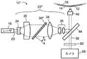
図1に示すように、顕微鏡システム10は、光透過試験管壁14と試験管中に配置されたフロートのフロート壁16との間の環状ギャップ12のおおむね平面の部分に配置されたバフィーコート・サンプルと一致する顕微鏡視野を撮像する。そのようなバフィーコート・サンプルを取得し準備するための適切な方法および装置は、例えば、米国特許出願公開第2004/0067162A1号および米国特許出願公開第2004/0067536A1号に開示されている。 As shown in FIG. 1, the
顕微鏡の視野は、試験管およびフロートの湾曲にもかかわらずおおむね平面である。というのは、顕微鏡の視野は、一般に、試験管壁14およびフロート壁16の曲率半径よりもサイズが遥かに小さいからである。視野は実質的に平面であるが、光透過試験管壁14とフロート壁16の間に配置されたバフィーコート・サンプルは、顕微鏡システム10の視野深度よりも実質的に大きな厚さであることがある。 The field of view of the microscope is generally flat despite the curvature of the test tube and float. This is because the field of view of the microscope is generally much smaller in size than the radius of curvature of the
試験管は、環状ギャップを横切って顕微鏡視野を走査するのに適した方法で、顕微鏡システム10に対して固定された位置に取り付けられている。これから述べるように、好ましくは、バフィーコート・サンプルを含む環状ギャップにわたって視野の相対的な回転走査および/または平行移動走査を実現するために適した機構が設けられる。 The test tube is mounted in a fixed position relative to the
顕微鏡システム10は、ガスレーザ、固体レーザ、半導体レーザ・ダイオードなどのレーザ18を含み、このレーザ18は、照明波長と、形状が一般にガウス状またはほぼガウス状の不均一空間分布とを有するレーザビームの形態の光源光20(図1に破線で図示されている)を発生する。上記不均一空間分布は、ビームの中心領域で最高強度を有し、ビームの中心からの距離の増加と共に強度が減少している。光学素子列22は、空間的に不均一な光源光20を受け取りかつ補正された空間分布を出力するように構成されている。 The
ビーム・スプレッダ(Beam Spreader)は、レーザビームをおおむね発散させる凹レンズ24と、ビーム・ホモジナイザ30のガウス空間特性の直径に実質的に整合するより大きな直径の広がったビームを平行にするコリメーティング・レンズ26と、を含む。ビーム・ホモジナイザ30は、光源光のガウスまたは他の不均一分布を実質的に均質化することによって、広がったレーザビームを平らにして、改善された空間的均一性を有する出力光を生成する。 A beam spreader collimates a
いくつかの実施形態では、ビーム・ホモジナイザ30は、逆ガウス・プロファイルに対応する空間的に不均一な吸収プロファイルを有して動作する。そのような実施形態では、ビーム・ホモジナイザは、広がったレーザビームの最高強度の中心領域に対応する中心領域で最大吸収を有し、広がったレーザビームのより低強度の外周領域に対応する周辺でより低い吸収を有するか、または吸収を有しない。 In some embodiments, the
他の実施形態では、ビーム・ホモジナイザ30は、例えば適切なレンズ対を使用して、広がったレーザビームの面積全体にわたって光強度を均質化するように、屈折により光を再分配する。屈折ビーム・ホモジナイザは、広がったレーザビームの高強度の中心領域からより低強度の周辺領域に光を屈折する。 In other embodiments, the
集束レンズ34および協働レンズ(Cooperating Lenses)36は、広がって平らになったレーザビーム或いは均質化されたレーザビームを、焦点を顕微鏡視野に合わされた対物レンズ40に入力するために望ましいビーム直径まで減少させる。ダイクロイック・ミラー44は、レーザビームの波長または波長範囲の光を実質的に反射し、かつバフィーコート・サンプル中の希少細胞に標識付けするために使用される蛍光染料の蛍光波長または波長範囲の光を実質的に透過するように選ばれる。 Focusing
固定光学部品24、26、30、34、36を含む光学素子列22は、対物レンズ40で顕微鏡視野に焦点を合わされたとき実質的に顕微鏡視野全体にわたって実質的に均一な静的照明を実現する補正された空間分布を、対物レンズ40に出力するように構成されている。対物レンズ40は、補正された照明を顕微鏡視野に集束させる。対物レンズ40は、単一の対物レンズを含んでもよく、または2以上の対物レンズを含んでもよい。顕微鏡システム10の焦点深度は、例えば、対物レンズ40と光透過試験管壁14の間の距離を調整することによって、調整可能である。追加して、または代わりに、対物レンズ40の中の2以上のレンズまたはレンズ要素を相対的に動かすことによって、焦点深度が調整されてもよい。 The
ビーム・ホモジナイザ30は、補正された直径のガウス入力ビームに対して実質的に均一な均質化ビームを出力するように設計されている。しかし、対物レンズ40は、一般に、いくらかの空間的不均一を生じさせる。したがって、拡大レンズ24、コリメーティング・レンズ26、集束レンズ34、および/または集束レンズ36などの固定光学部品の1または複数は、場合によっては、対物レンズ40で焦点を合わせたときビームが顕微鏡視野の実質的に均一な静的照明を実現するように、空間的不均一を空間分布の中に生じさせるように構成される。いくつかの考えられる実施形態では、この補正空間不均一は、その目的のために光学素子列22に含まれる1または複数の専用光学部品(図示省略)が生じさせる。 The
顕微鏡視野の実質的に均一な静的照明は、顕微鏡視野内に配置された任意の蛍光染料標識付き上皮細胞の蛍光発光を引き起こす。さらに、蛍光染料は、一般に、バフィーコートに低強度の背景蛍光を与える。この蛍光は、対物レンズ40で捕らえられ、捕らえられた蛍光50(図1に点線で図示される)は、ダイクロイック・ミラー44を通過し、さらに、光源のどんな迷光も除去する光学フィルタ52を通過して、カメラシステム56で撮像される。カメラシステム56は、例えば、後の画像処理のためにコンピュータ、メモリ・カード、または他の不揮発性メモリに格納することができる電子画像を取得する電荷結合デバイス(CCD)カメラを含んでもよい。 The substantially uniform static illumination of the microscopic field causes the fluorescence emission of any fluorescent dye-labeled epithelial cells placed in the microscopic field. In addition, fluorescent dyes generally give the buffy coat a low intensity background fluorescence. This fluorescence is captured by the
図2および3を参照して、他の適切な顕微鏡システムを説明する。 With reference to FIGS. 2 and 3, another suitable microscope system will be described.
図2は、図1の固定ビーム・ホモジナイザ30が固定ディフューザ30’に置換されて光学素子列22’が異なっている点を除いて、図1の顕微鏡システム10と同様の顕微鏡システム10’を示す。ディフューザ30’は、例えば、フィジカル・オプティックス社(Physical Optics Corporation:カリフォルニア州、トランス)から入手可能なホログラフィック・ディフューザであってもよい。そのようなホログラフィック・ディフューザは、改善された空間的均一性を与えるように光を拡散するランダム化非周期光学構造を実現するホログラムを使用する。しかし、光の拡散は、いくらかの付随したビーム発散も与える。一般に、光の拡散が強いほど、より多くの空間的均一性を与える傾向があるが、また、より大きなビーム発散を生じさせる傾向がある。ホログラフィック・ディフューザは、発散角の半値全幅(FWHM)に従って適切に分類され、一般に発散角が大きいほど、拡散が大きくなり光均一性が大きくなるが、ビーム発散の増加のために顕微鏡システム10’の光損失の増加をもたらす。 FIG. 2 shows a
顕微鏡システム10’のいくつかの実施形態では、ディフューザ30’は、約10°以下のFWHMを有する低角度ディフューザである。低角度ディフューザは、一般に、比較的少ない発散、したがって照明処理能力の比較的優れた効率を実現するのに好ましい。しかし、発散FWHMが小さ過ぎる場合には、ディフューザは、十分なビーム均一性を与えるのに十分な光拡散を実現しない。低拡散は、ガウス分布を均質化するディフューザ30’の能力を低下させ、また、スペックルを除去するディフューザ30’の能力を低下させる。 In some embodiments of the microscope system 10 ', the diffuser 30' is a low angle diffuser having a FWHM of about 10 degrees or less. Low angle diffusers are generally preferred to achieve relatively low divergence and thus relatively good efficiency of lighting throughput. However, if the divergence FWHM is too small, the diffuser does not achieve sufficient light diffusion to provide sufficient beam uniformity. Low diffusion reduces the ability of the diffuser 30 'to homogenize the Gaussian distribution and reduces the ability of the diffuser 30' to remove speckle.
図3に示すように、他の実施形態の顕微鏡システム10''は、顕微鏡システム10’と同様のものであり、顕微鏡システム10’のディフューザ30’と同様のディフューザ30''を使用した光学素子列22''を備える。しかし、ディフューザ30''は、光源光20のスペックル・パターンを実質的に減少させるために、光学素子列22''の光路に対して角度θで傾斜している。どんな特定の動作理論にも限定されることなく、傾斜させることで、スペックル・パターンはより高い空間周波数にシフトし、実際上、スペックル・サイズがより小さくなる。周波数シフトしたスペックルが撮像ピクセル・サイズよりも実質的に小さくなるように傾斜させることで、スペックル・サイズは、空間的にシフトする。 As shown in FIG. 3, a
いくつかの実施形態では、光学素子列22''の光路に対して少なくとも約30°の傾斜角θが使用され、これによって、約5°程度の低いFWHMを有するディフューザ30''のスペックルが実質的に減少することが分かった。他方で、約45°を超える傾斜角θは、5°のFWHMを有する低角度ディフューザの場合でも、散乱の増加のために照明処理能力の効率を低下させることが分かった。 In some embodiments, a tilt angle θ of at least about 30 ° with respect to the optical path of the
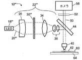
図4に示すように、本明細書で開示された顕微鏡システムは、試験管中に含まれた、または試験管で支持されたサンプルの撮像以外に、他の顕微鏡検査の用途にも適している。図4において、顕微鏡システム10'''は、前の顕微鏡システム10、10’、10''で使用されたレーザ18ではなく、発光ダイオード(LED)18'''を光源として含む。LED18'''は、平行レーザビームではなく発散する光源光20'''を出力するので、図4に示すように、光学素子列22'''は、ビームを広げる凹レンズ24が適切に省略される点で、変更されている。代わりに、レンズ24の位置にレンズが含まれてもよいが、このレンズは、コリメーティング・レンズ26によるコリメーションのために適切な発散角調整を行うように選ばれる。光学素子列10'''は、ディフューザ30’、30''に似たディフューザ30'''を使用する。LED18'''は、非可干渉光を出力するので、スペックルはおおむね存在しない。しかし、LED18'''の出力は、一般に、非ガウス分布、例えばランベルト分布を有している。光源光20'''のこれらの特性を考慮してディフューザ30'''は傾斜していないが、いくつかの場合には、ディフューザ30'''は、図2の顕微鏡システム10’でレーザビーム光源光20に空間的均一性を与えるために使用される無傾斜ディフューザ30’よりも小さな発散角FWHMを有することができる。 As shown in FIG. 4, the microscope system disclosed herein is suitable for other microscopic applications besides imaging of samples contained in or supported by a test tube . In FIG. 4, the
図4の顕微鏡システム10'''は、顕微鏡システム10'''が平面スライド60の上に配置されたサンプルを撮像する点で、顕微鏡システム10、10’、10''とさらに異なっており、この平面スライド60は、場合によっては、随意のカバー・ガラス62で覆われる。スライド60は、サンプル全体にわたった走査を可能にするようにx−y平行移動平面ステージ64の上に配置される。当然ながら、LED18'''および光学素子列22'''は、また、図1〜3に示された光透過試験管壁14とフロート壁16の間の環状ギャップ12に配置されたバフィーコート・サンプルを撮像するのにも適している。一方、レーザ18および光学素子列22、22’、22''は、また、図4に示されたスライド60の上の平面サンプルを撮像するのにも適している。 The
光学素子列22、22’、22''、22'''は、その部品が回転しない、相対的に振動しない、またはそうでなければ相対的に動かないという意味で固定された部品を有している。しかし、サンプルに対する視野の相対的な走査を可能にするように、光学素子列および対物レンズ40を全体として動かすこと、および/またはビーム・ステアリング要素を含むことなどは考えられる。 The
試験管中に含まれた、または試験管で支持された環状サンプルを撮像する適切な顕微鏡システムは、説明した通りである。環状ギャップ12は、一般に、顕微鏡対物レンズ40の視野深度よりも実質的に大きな厚さである。試験管壁12およびフロート壁16は、一般に、試験管またはフロートの全表面にわたって均一でない。顕微鏡対物レンズ40は、一般に、調整可能な焦点深度を有するが(内部光学部品を動かすことによって、および/または対物レンズ40を試験管壁14の方に、または試験管壁14から離すように動かすことによって調整される)、調整範囲は限定されている。したがって、試験管が回転するときに、および対物レンズ40または試験管が管軸に沿って平行移動するときに、対物レンズ40に近い表面が対物レンズ40から所定距離、離れた位置にあるように、試験管は保持されるべきである。 A suitable microscope system for imaging an annular sample contained in or supported by a test tube is as described. The
次に、それを実現するのに適当な試験管ホルダについて説明する。 Next, a test tube holder suitable for realizing this will be described.
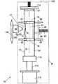
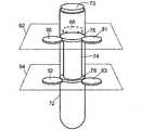
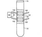
図5〜図10に示すように、試験管ホルダ70は、試験管栓73で密閉された試験管72をその中に取り付けている。密閉された試験管72は、フロート74と、例えば米国特許出願公開第2004/0067162A1号および第2004/0067536A1号に記載されているように、赤血球、血漿、およびバフィーコートを含む成分を分離するように適切に処理され遠心分離機にかけられた血液と、を含む。フロート74は、濃縮赤血球成分の密度(1.090g/ml)よりも小さく、かつ血漿成分のそれよりも大きな密度(1.028g/ml)を有している。したがって、遠心分離機にかけた後で、フロート74は、図6に示す試験管軸75に沿って、濃縮赤血球層と血漿層の間、すなわちバフィーコートと対応する位置に配置される。その結果、バフィーコートは、遠心分離機にかけた後、試験管壁14とフロート壁16の間の環状ギャップ12に配置される(図6の表示を参照されたい)。フロート74の両端部の環状密閉突出部76、78は、試験管が静止しているときに試験管72の内壁に係合して環状ギャップ12を密閉している。しかしながら、試験管72は、遠心分離処理中に拡径して、流体が突出部76、78を通過・流通できる状態となり、これにより、バフィーコートを環状ギャップ12に実質的に集めることができるようになっている。 As shown in FIGS. 5 to 10, the
少なくとも1つの第1のアライメント軸受、すなわち、実施例の試験管ホルダ70において放射状に間隔を開けて配列された2つの第1のアライメント軸受80、81は、環状サンプリング領域12の第1の側に配置されている。少なくとも1つの第2のアライメント軸受、すなわち、実施例の試験管ホルダ70において放射状に間隔を開けて配列された2つの第2のアライメント軸受82、83は、試験管軸75に沿って環状サンプリング領域12の第1の側と反対の第2の側に配置されている。アライメント軸受80、81、82、83は、止め部材85(図8にだけ図示されている)によってハウジング84に固定された固定転がり軸受である。 At least one first alignment bearing, i.e. two
少なくとも1つのバイアス軸受、すなわち、実施例の試験管ホルダ70の2つのバイアス軸受86、87は、アライメント軸受80、81、82、83から放射状に間隔を開けて配置され、さらに、バネ90に付勢されて試験管72をアライメント軸受80、81、82、83に押し付けることにより、対物レンズ40に近い環状サンプリング領域12の側をアライメント軸受80、81、82、83に対して位置合わせするようになっている。実施例の試験管ホルダ70では、2つの第1のアライメント軸受80、81および第1のバイアス軸受86は、放射状に120°の間隔を開けて配置され、環状サンプリング領域12の第1の側の第1の共通平面92に置かれている。同様に、2つの第2のアライメント軸受82、83および第2のバイアス軸受87は、放射状に120°の間隔を開けて配置され、環状サンプリング領域12の第2の側の第2の共通平面94に置かれている。バネ90は、ハウジング84に固定され、部材98によってバイアス軸受86、87と接続している。 At least one bias bearing, i.e., two
より一般的には、軸受80、81、86および軸受82、83、87は、120°以外の放射間隔を有することができる。例えば、バイアス軸受86は、アライメント軸受80、81の各々から等しい放射角の間隔で配置されてもよい。特定の実施例として、バイアス軸受86は、アライメント軸受80、81から135°の間隔で配置されてもよく、この特定の実施例では、2つのアライメント軸受80、81は、90°の間隔で配置される。 More generally, the
場合によっては、第1の共通平面92は、軸受80、81、86が突出部76のところで試験管72を押し付けるようにフロート突出部76を含み、同様に、第2の共通平面94もまた、場合によっては、軸受82、83、87が突出部78のところで試験管72を押し付けるようにフロート突出部78を含む。この方法によって、環状サンプル領域12を変形させる可能性が減少する。バイアス軸受86、87は、試験管72をアライメント軸受80、81、82、83に押し付ける方向に付勢する付勢力96を与える。 In some cases, the first
ハウジングは、試験管軸75に沿って延びる覗き窓100を含む。対物レンズ40は、覗き窓100を通して、対物レンズ40に近い環状サンプル領域12の側部を見る。いくつかの実施形態では、平行移動範囲の両方向矢印104で示されるように、対物レンズ40は、試験管軸75に沿って直線的に平行移動可能である。これは、例えば、試験管ホルダ70に対して平行移動可能な共通基板に対物レンズ40および光学素子列22、22’、22''、または22'''を取り付けることによって、達成することができる。他の方法では、顕微鏡システム10、10’、10''、10'''は固定され、窓100を横切って対物レンズ40を相対的に平行移動させるように、ハウジング84を含む試験管ホルダ70がユニットとして平行移動される。さらに他の実施形態では、光学素子列22、22’、22''、または22'''を固定したままで、対物レンズ40が移動し、ビームを対物レンズ40に入力するように適切なビーム・ステアリング部品(図示省略)が設けられる。また、例えば、試験管72の方に向けて、または試験管72から遠ざかるように対物レンズ40を焦点調節範囲106にわたって動かすことによって、対物レンズ40の焦点を合わせることができる(平行移動範囲104および焦点調節範囲106は、図6のみに示されている)。 The housing includes a
環状サンプリング領域12の走査は、試験管軸に沿った平行移動と、試験管軸75のまわりの試験管72の回転との両方を必要とする。回転動作を実現するために、回転継手110は、シャフト114を介して回転継手110と接続されたモータ114によって選択的に加えられるトルクに応答して、試験管軸75のまわりに試験管72を回転させるように構成されている。実施例の試験管ホルダ70の回転継手110は、試験管72の一端または底部で試験管と接続している。試験管72の他端で、バネ荷重キャップ116が試験管72の栓73を押圧して、上記回転に付随して試験管72に試験管軸75に沿った平行移動すべりが生じるのを防止している。 Scanning the
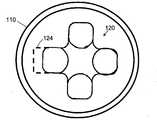
特に図9および10に示すように、いくつかの実施形態では、回転継手110は、試験管72の凹凸付き底部122と噛み合うように構成された凹凸120を有する凹凸付き継手である。図9および10の例示の実施例では、継手110の凹凸120は、試験管72の凹凸付き底部122の4つの先端部を受け入れる4つのくぼみを含む。他の凹凸形状を使用することもできる。 9 and 10, in some embodiments, the rotary joint 110 is a concavo-convex joint having a concavo-convex 120 configured to mate with the concavo-
いくつかの実施形態では、試験管72の凹凸付き底部122が回転継手110の凹凸120と噛み合ったときに、継手110および試験管底部122それぞれの適当な回転非対称な形状部分124、126(図9および10に透過表示されている)によって凹凸120と凹凸付き底部122が結合して、試験管72の絶対的な回転位置を決定する。このため、試験管72を試験管ホルダ70から取り外して、再び取り付けた場合でも、絶対回転位置(例えば、絶対角度値として度の単位で測定される)を維持することができる。 In some embodiments, when the concavo-
絶対角度位置を実現する他の方法では、試験管は、場合によっては、試験管の絶対回転位置を示す基準の目印、例えば光学的に読取り可能な反射基準目印(図示省略)を含む。 In other ways of achieving absolute angular position, the test tube optionally includes a reference landmark indicating the absolute rotational position of the test tube, for example, an optically readable reflective reference landmark (not shown).
いくつかの実施形態では、第2の側のアライメント転がり軸受82、83は省略され、回転継手110が、試験管軸75に沿って環状サンプリング領域12の第1の側と反対の第2の側に配置された少なくとも1つの第2のアライメント軸受を規定する。そのような実施形態では、回転継手は、機械的に駆動されるアライメント軸受として作用して、試験管72の位置決めと回転の両方を行う。場合によっては、いくつかの実施形態で、第2の側のバイアス軸受87は、対応する転がり軸受82、83と共に省略される。 In some embodiments, the second side
他方で、いくつかの他の考えられる実施形態では、回転継手110が省略され、1または複数の転がり軸受81、82、83、84、86、87は、試験管72を回転させるように機械的に駆動される。そのような実施形態では、駆動される転がり軸受は、回転継手として作用する。駆動される軸受は、1または複数のアライメント軸受81、82、83、84であってもよく、または1または複数のバイアス軸受86、87であってもよい。 On the other hand, in some other possible embodiments, the rotary joint 110 is omitted, and the one or more
ハウジング84は、試験管72を試験管ホルダ70に取り付けるための開き蓋または開き戸130を備える(図5は開いた状態、図6は閉じた状態をそれぞれ示している)。開き蓋または開き戸130が開いているとき、バネ荷重キャップ116は、試験管72の栓73から持ち上げられる。場合によっては、ホルダ70への試験管72の取付けまたは取外しを容易にするために、バイアス軸受86、87を支える支持部材98は、バネ90の付勢力に逆らって試験管72からバイアス軸受86、87を手操作で引き離すための手操作ハンドルまたはレバー(図示省略)を含む。 The
有利なことには、試験管ホルダ70は、真っ直ぐな側面を有する例示の試験管72を位置合わせすることができる。また、試験管ホルダ70は、僅かに先細りした試験管を収容し位置合わせすることができる。先細の試験管の保持位置は、図6に破線134で示され、この破線134は、先細の試験管の傾斜した縁部を示している。例示の傾斜134によって、回転継手110に最も近い試験管の端部が、バネ荷重キャップ116に最も近い試験管の端部より小径になっている。図6に示すように、バイアス軸受86、87は、試験管をアライメント軸受81、82、83、84に押し付けて、傾斜134にもかかわらず、対物レンズ40に近い環状サンプル領域12の部分の位置合わせを維持する。当然のことながら、ホルダ70は、回転継手110に最も近い端部の直径がバネ荷重キャップ116に最も近い端部よりも大きい逆の傾斜を有する試験管を同様に収容し位置合わせすることができる。 Advantageously, the
大きな傾斜がある場合、または非常に偏心した断面または非円形断面を有する試験管の場合には、アライメント軸受81、82、83、84に押し付ける付勢では、傾斜または断面偏心率または楕円率に完全に対応することはできない。その理由は、第1のアライメント軸受81と82の放射間隔および第2のアライメント軸受83と84の放射間隔によって、もっと細い管が第1のアライメント軸受81と82の間のギャップの中に、また第2のアライメント軸受83と84の間のギャップの中にいっそう深くに至ることができるようになるからである。 In the case of a large inclination, or in the case of a test tube with a very eccentric or non-circular cross section, the biasing against the
図11Aおよび図11Bに示すように、楕円断面を有する変形試験管72’は、支持フロート突出部ごとに1組の3個の軸受を使用してより正確に位置合わせされている。この場合に、3個の軸受は、1つのアライメント軸受81’および2以上のバイアス軸受86’を含む。アライメント軸受81’は、対物レンズ40と同じ放射位置にある(図11Aおよび図11Bに透過表示されている)。楕円試験管12’が回転するときに、撮像される側が楕円試験管72’の短軸に対応していようと(図11A)、または撮像される側が楕円試験管72’の長軸に対応していようと(図11B)、アライメント軸受81’に押し付けるように付勢された撮像される側は、放射方向の一致した対物レンズ40と正確に位置合わせされた状態にある。 As shown in FIGS. 11A and 11B, the
図12に示すように、他の変形例では、試験管軸75と平行な力成分を与えて試験管72を回転継手110の中に押し込むように、軸受140は、試験管72の管軸75に対して傾斜している。この配列では、バネ荷重キャップ116は場合によっては省略される。というのは、軸受140を傾斜させることにより、回転中の試験管72の平行移動すべりを妨げるからである。 As shown in FIG. 12, in another modification, the
図13に示すように、他の変形例では、フロート74’は螺旋状の突出部76’を含み、傾斜軸受142は、試験管72の回転に対して密閉突出部76’に追従するように、試験管軸75に沿って螺旋ピッチに従った間隔で配置されている。この方法では、傾斜軸受142は、試験管72を管軸75に沿って平行移動させる力を与え、その結果、対物レンズ40は、環状ギャップ12’を走査しながら、平行移動することなしに固定位置に維持されることが可能になる。この方法では、転がり軸受142は、試験管72の回転を生じさせるように適切にモータが取り付けられている。すなわち、転がり軸受142は、回転継手としても作用する。 As shown in FIG. 13, in another variation, the
図14に示すように、他の変形例では、機械的付勢力はバイアス軸受以外の機構によって与えられてもよい。図14の実施例では、試験管72はアライメント軸受181、182、183、184の上に載って水平に配置され、対物レンズ40は試験管72の下に取り付けられている。フロート74を含んだ試験管72の重さ186(図14に下向きの矢印186で図示された重さ)が、試験管72をアライメント軸受181、182、183、184に押し付ける機械的付勢力として作用する。他の考えられる実施形態では、真空チャック、プラスの空気圧、磁力または他の機械的付勢力が、試験管をアライメント軸受に押し付けるために使用される。アライメント軸受181、182、183、184は、アライメント軸受181、182、183、184が回転継手として作用するように機械的に回転されてもよく、または別個の回転継手が設けられてもよい。 As shown in FIG. 14, in other variations, the mechanical biasing force may be provided by a mechanism other than the bias bearing. In the embodiment of FIG. 14, the
図15に示すように、軸受は、転がり軸受以外であってもよい。例えば、ローラ、玉軸受、またはブッシュ面であってもよい。図15に示される変形試験管ホルダでは、1組の玉軸受204を試験管72に押し付けて、ハウジング200のブッシュ面で構成されたアライメント軸受211、212に試験管72を押し付けるバネ202の固定部を、ハウジング200が実現している。試験管が回転するときに試験管を支えるバイアス軸受および/またはアライメント軸受として、他の型の軸受が使用されてもよい。 As shown in FIG. 15, the bearing may be other than a rolling bearing. For example, it may be a roller, a ball bearing, or a bush surface. In the deformed test tube holder shown in FIG. 15, a fixed portion of a
図13の実施形態以外の例示の実施形態では、試験管が試験管ホルダの中で平行移動されないで、代わりに、対物レンズ40を平行移動させることによって、または、試験管と試験管ホルダをユニットとして平行移動させることによって、走査の平行移動部分が実現されている。他の考えられる実施形態では、例えば、試験管72を試験管軸75に沿って平行移動させるために、モータ112を回転継手112と接続するシャフト114に直線平行移動機能を持たせることによって、対物レンズを固定された状態に保ちかつ試験管を試験管ハウジングの中で平行移動させることが考えられる。 In an exemplary embodiment other than the embodiment of FIG. 13, the test tube is not translated in the test tube holder, but instead by translating the
試験管中に含まれた、または試験管で支持された環状サンプル領域を撮像するための適切な顕微鏡システムおよび試験管ホルダは、説明した通りである。なお、環状サンプリング領域は、試験管壁14とフロート壁16の間のギャップ12に含まれた例示の流体サンプル以外であってもよい。例えば、環状サンプル領域は、試験管の外面に付着された膜または塗膜であってもよく、或いは試験管の内面に付着された膜または塗膜であってもよい。さらに、「試験管」という用語は、例示の従来の試験管72以外の他の管状サンプル容器を含むものとして広く解釈されるべきである。例えば、試験管は、関心のある対象のサンプルを円柱状のロッドの外側に塗布するために、含有ボリューム、固体物体、または関心のある他の対象の中に挿入された円柱状のロッドであるかもしれないし、または、試験管は、地質学上の円柱状コア・サンプルなどであってもよい。 Suitable microscope systems and test tube holders for imaging an annular sample region contained in or supported by a test tube are as described. The annular sampling region may be other than the exemplary fluid sample included in the
環状スライドまたは、試験管中に含まれるか試験管で支持された環状サンプル領域からデータを取得するための適切な顕微鏡システムおよび試験管ホルダは、説明した通りである。以下に、環状生体液層の蛍光染料標識付き細胞を識別または定量化する適切な処理方法を説明する。 Suitable microscope systems and test tube holders for acquiring data from an annular slide or an annular sample region contained in or supported by a test tube are as described. In the following, an appropriate processing method for identifying or quantifying the fluorescent dye-labeled cells in the annular biological fluid layer will be described.
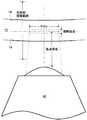
図16には、特定の測定パラメータが図示されている。対物レンズ40は、視野(FOV)にわたって、また焦点深度にある視野深度にわたって像を形成する。図16において、焦点深度は、対物レンズ40に対して示されている。しかし、焦点深度は、他の基準に対して示されてもよい。いくつかの実施形態では、対物レンズ40の焦点深度は約20ミクロンであり、一方で、試験管壁14とフロート壁16の間の環状ギャップ12は、約50ミクロンである。しかし、環状ギャップ12に対応する焦点深度は、試験管および/またはフロートまたは他の要素の不均一のために実質的に変化することがある。予期されることであるが、環状ギャップ12は、周囲を取り囲む深度範囲(Encompassing Depth Range:以下、包括的深度範囲と称する。)の中のどこかにある。いくつかの実施形態では、300ミクロンの包括的深度範囲が適切であることが分かった。この寸法は例であって、特定の対物レンズ40、光透過試験管、フロート、使用される遠心分離の態様または他のサンプル処理などに依存して、特定の実施形態に関して実質的に異なることがある。 FIG. 16 shows specific measurement parameters. The
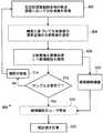
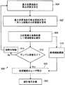
図17には、1つの適切なデータ取得方法300が図示されている。処理工程302で、包括的深度範囲に亘る複数の焦点深度で分析画像が取得される。深度方向にズレが生じないようにするために、工程302で取得される分析画像の数は、少なくとも包括的深度範囲を対物レンズ40の視野深度で割ったものに対応すべきである。 FIG. 17 illustrates one suitable
いくつかの実施形態では、分析画像は、随意の工程304で処理され、画像の明るさに基づいて、生体液層(バフィーコート層のような)の深度付近で1または複数の分析画像が特定される。この随意選択は、蛍光染料が一般に背景蛍光を引き起こすという観察結果を利用する。背景蛍光は、取得分析画像で全体的な画像明るさの増加として検出される。画像の明るさは、平均ピクセル強度、二乗平均ピクセル強度などの様々な方法で推定することができる。 In some embodiments, the analysis image is processed in
画像処理工程306で、分析画像、または随意選択工程304で選択された1または複数の分析画像は、観察された特徴部分を候補細胞として識別するために、フィルタ処理、閾値化などのような適切な技術を使用して処理される。生体液層の染料標識付き細胞の密度は、一般に、1視野当たりに染料標識付き細胞が約1未満である。したがって、識別される候補細胞の割合は一般に低い。候補細胞が画像処理306で識別されたとき、適切な候補細胞標識が1組の候補細胞標識310に加えられる。例えば、候補細胞標識は、適切な索引システムおよび候補細胞の特徴部分のx−y座標に基づいて画像を識別することができる。希少細胞の密度は一般に低いが、それにもかかわらず、画像処理306が、時々、単一の分析画像で2以上の候補細胞を識別することがあることは予想される。他方で、いくつかの分析画像で、候補細胞が識別されない可能性もある。 In the
判断点312で、サンプル走査が完了したかどうかが決定される。完了していないときには、工程314で視野が動かされる。例えば、試験管72の回転と試験管軸75に沿った対物レンズ40の平行移動との組合せで、環状ギャップ12の生体液サンプル全体にわたって、視野を相対的に走査することができる。代わりに、図13の管ホルダを使用して、試験管72を螺旋状に動かすことによって走査が行われる。新しい視野ごとに、処理工程302、304、306が繰り返される。 At
サンプル走査が完了したことを判断点312が示すと、使用者検証処理320が随意に行われ、かかる処理において人間の分析者が各細胞候補を確認または却下することができる。画像処理306が十分に正確である場合には、使用者検証処理320は省略するようにしてもよい。 When
人間分析者によって確認された細胞の適切な統計を計算するために、統計分析322が行われる。例えば、生体液サンプルの体積または質量が分かっている場合には、単位体積または単位重さ当たりの希少細胞の密度(例えば、細胞/ミリメートルまたは細胞/グラム)を計算することができる。他の統計分析方法では、確認された細胞の数が合計される。標準試験管、標準フロート、標準全血液サンプル量、および標準化された遠心分離処理などの標準バフィーコート・サンプル構成が使用されるとき、これは適切な計量である。また、統計分析322は、閾値警報を含むことがある。例えば、細胞数または密度計量が第1の閾値よりも大きい場合、この警報は、さらに進んだ医療検査を必要とする癌の高い可能性を示してもよく、一方で、細胞数または密度が第2のより高い閾値を超えた場合には、この警報は、緊急の医療対応処置を必要とする癌の高い確率を示してもよい。
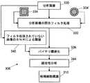
図18には、部分的に変更した取得方法300’が図示されている。処理工程304’で、分析画像以外の入力を使用して、最初に、最大背景蛍光強度の焦点深度が決定され、その後に、最大背景蛍光の焦点深度付近で1または数個の分析画像を取得する処理302’が行われる。例えば、様々な深度で低分解能画像を取得して、探索処理304’が行われてもよい。深度方向にズレが生じないようにするために、工程304’で取得される低分解能画像の数は、少なくとも包括的深度範囲を対物レンズ40の視野深度で割ったものに対応すべきである。他の方法では、大面積の輝度センサ(図示省略)が捕えられた蛍光50に結合されることがあり(例えば、カメラ56の部分ミラーを使用して、またはカメラ56に組み込まれた強度計量器を使用して)、さらに対物レンズ40の焦点が、包括的深度範囲全体にわたって掃引されることがある。この掃引中のセンサまたは計量器のピーク信号は、最高明るさを与える焦点を示す。 FIG. 18 illustrates a partially modified acquisition method 300 '. In
処理工程304’で測定された生体液サンプルの深度を用いて、取得処理302’は、最高明るさの識別された焦点深度近傍で僅か1つまたは数個の分析画像を取得する。生体液層を完全にカバーすることを保証するために、取得される分析画像の数は、少なくとも環状ギャップ12の厚さを対物レンズ40の視野深度で割ったものであるべきである。例えば、環状ギャップ12が約50ミクロンの厚さであり、視野深度が約20ミクロンである場合には、3つの分析画像が適切に取得される。すなわち、最高明るさの焦点深度で1つ、約15〜25ミクロンだけ大きい焦点深度で1つ、さらに、約15〜25ミクロンだけ小さい焦点深度で1つである。 Using the biological fluid sample depth measured in process step 304 ', acquisition process 302' acquires only one or several analysis images near the identified depth of focus at the highest brightness. In order to ensure complete coverage of the biological fluid layer, the number of analysis images acquired should be at least the thickness of the
部分的に変更した取得方法300’の有利点は、分析画像を取得するより前に焦点深度が決定されるので、取得される高分解能分析画像の数が少なくなることである。決定された焦点深度、僅かに大きな焦点深度および僅かに小さな焦点深度で分析画像を取得して、決定された焦点深度の範囲を確定することは有利である。この方法は、蛍光背景が最大である深度から外れた深度で希少細胞が最適に撮像されることがある可能性を明らかにする。 An advantage of the partially modified acquisition method 300 'is that the number of high resolution analysis images acquired is reduced because the depth of focus is determined prior to acquiring the analysis images. It is advantageous to acquire an analysis image with a determined depth of focus, a slightly larger depth of focus and a slightly smaller depth of focus to determine the range of determined depth of focus. This method reveals the possibility that rare cells may be optimally imaged at depths outside the depth at which the fluorescent background is maximum.
図19を参照して、画像処理306の適切な実施形態を説明する。この実施形態は、分析画像330の任意の細胞候補を識別するために、予想される希少細胞サイズについての演繹的知識(Priori Knowledge)を活用する。照合フィルタ処理332で、適切なフィルタカーネル(Filter Kernel)が画像と共に畳み込まれる。照合フィルタ処理332は、分析画像330中の希少細胞の画像の予想サイズと同等のサイズを有するフィルタカーネルを使用する。 A suitable embodiment of the
引き続き図19を参照し、さらに図20および21を簡単にさらに参照して、いくつかの実施形態では、正方形フィルタカーネル334が使用される。このカーネル334は、各々+1の値を有するピクセルの中心正領域、および各々−1の値を有するピクセルの外側負領域を含む。正領域の面積は、負領域の面積とおおよそ同じ大きさであるべきである。内側領域か外側領域かのどちらか以外の点は、ゼロのピクセル値を有する。フィルタに僅かに正または僅かに負の応答を与えるために、+1および−1以外の他のピクセル値が、内側および外側領域にそれぞれ使用されてもよい。 With continued reference to FIG. 19 and with further reference briefly to FIGS. 20 and 21, in some embodiments, a
さらに図19に示すように、照合フィルタ処理は、背景照明によって生じたオフセットを除去するか、減少させ、また、希少細胞の信号対雑音比(SNR)を改善する。信号は、正照合面積にある点の数だけ増加し、一方で、雑音は、正照合面積と負照合面積の両方にある点の数だけ増加する。SNRの利得は、信号が直接増すことから生じ、一方で、組み合わされたサンプルの数の二乗平均(RMS)値または平方根として増す。N個の正点およびN個の負点を有するフィルタでは、N/√(2N)または√(N/2)の利得が得られる。 Furthermore, as shown in FIG. 19, the matching filter process removes or reduces the offset caused by background illumination and improves the signal-to-noise ratio (SNR) of rare cells. The signal increases by the number of points in the positive verification area, while the noise increases by the number of points in both the positive and negative verification areas. The SNR gain results from a direct increase in signal, while increasing as the root mean square (RMS) value or square root of the number of combined samples. A filter with N positive points and N negative points can provide a gain of N / √ (2N) or √ (N / 2).
正方形フィルタカーネル334は、そのエッジ(縁)が分析画像330のx−y座標方向と並んでいるので、計算上有利である。場合によっては、丸いフィルタカーネル334’またはそれ以外の形をしたカーネルが、正方形フィルタカーネル334の代わりに使用される。しかし、丸いフィルタカーネル334’は、正方形フィルタカーネル334よりも計算的に費用がかかる。丸いフィルタカーネル334’と比べて正方形フィルタカーネル334の他の有利点は、正方形フィルタ334のフィルタ・エッジ長さの合計が、検出サイズの2倍から検出サイズの1.414倍に減少することである。このことで、エッジ効果が減少し、分析画像330のエッジに比較的近いデータを使用することが可能になる。 The
フィルタカーネルのサイズは、最良のSNR改善を実現するために、分析画像330中の染料標識付き細胞の予想画像サイズに実質的に整合するように選ばれるべきである。例えば、全体に10個のピクセルがある正(+1)領域を有する正方形フィルタカーネル334は、約10ピクセルの直径を有する細胞画像に対して最良のSNR改善を実現すると予想される。このような整合の場合には、信号は、約78倍に増加すると予想され、一方で、雑音は約14倍に増加すると予想され、約5.57:1のSNR改善が実現される。他方で、同じ正方形フィルタを使用するより小さな8ピクセル直径の細胞の場合のSNR改善は、約3.59:1であると予想される。同じ正方形フィルタを使用するより大きな14ピクセル直径の細胞の場合のSNR改善は、約3.29:1であると予想される。 The size of the filter kernel should be chosen to substantially match the expected image size of the dye labeled cells in the
照合フィルタ処理332は、様々な方法で実現することができる。1つの方法では、入力画像の各点は、正内側領域にある出力画像の全ての点に合計される。次に、外側の負領域にあるが内側の正領域にない出力画像の全ての点が、減算される。入力画像の各点には一度タッチ(Touch)するだけであるが、出力画像の各点には、外側ボックスのピクセル面積数の回数だけタッチする。 The
他の適切な方法では、出力画像の点ごとに、正の内側ボックスの中にある入力画像からの全ての点が読み取られ、合計される。次に、正の内側ボックスの外であるが負の外側ボックス内にある全ての点が、減算される。各出力画像ピクセルは僅か一度だけタッチするが、各入力画像ピクセルは、外側ボックスのピクセル数だけタッチする。 In another suitable method, for each point in the output image, all points from the input image that are in the positive inner box are read and summed. Next, all points outside the positive inner box but within the negative outer box are subtracted. Each output image pixel touches only once, but each input image pixel touches the number of pixels in the outer box.
他の適切な方法では、入力画像の現在行について2つの内部値、すなわち、負の外側ボックス距離(Negative outer box distance)の行の全ての点の合計値と、内側正ボックス距離(Inner positive box distance)の行の全ての点の合計値が作られる。現在行の全ての出力画像列点は、それらから除かれた外側ボックスの全ての点の入力画像合計を有する。内側正ボックス内の全ての出力画像列点は、内側正ボックス距離の入力画像行点の合計を2回加えられる。行合計は、1つの加算と1つの減算によって、行の次の点のために更新される。これによって、実施コストが減少してフィルタ・ボックスのほぼ高さであるようになる。 Another suitable method is that for the current row of the input image, there are two internal values: the total value of all points in the negative outer box distance row, and the inner positive box distance (inner positive box distance). The sum of all points in the (distance) line is created. All output image sequence points in the current row have the input image sum of all points in the outer box removed from them. All output image sequence points in the inner positive box are added twice the sum of the input image row points for the inner positive box distance. The row total is updated for the next point in the row by one addition and one subtraction. This reduces the cost of implementation so that it is approximately the height of the filter box.
照合フィルタ処理332においては、様々なエッジ条件を使用することができる。例えば、1つの方法では、分析画像330のエッジに重なるフィルタを有するどんな点に対しても出力が生成されない。この方法は、エッジのアーチファクト(Artifacts)を回避するが、有用な面積の減少した出力画像を生成する。他の適切なエッジ条件例では、エッジの全ての点にデフォルト値(例えば、ゼロまたは計算された平均レベルなど)が使用される。 In the matching
さらに、図19に示すように、照合フィルタ処理332の後でバイナリ(Binary)閾値化処理338が適用される。閾値化338を行う際の困難さは、適切な閾値の選択である。閾値選択は、いくつかの分析画像が細胞を含まないか、または1つの細胞だけ含むか、または数個すなわち2〜3個の細胞だけを含むか、という可能性によって複雑になる。1つの方法では、閾値は、フィルタ処理されたデータに見られるピーク・ピクセル強度より下の選択されたたパーセント値として選択される。しかし、その場合にピーク・ピクセル値は雑音の中にあるので、この閾値によって、細胞が存在しないとき雑音が検出されるようになる。他の方法は、固定閾値を使用することである。しかし、バックグラウンド強度が分析画像間で実質的に変化する場合、または、照合フィルタ処理がピクセル強度の動的範囲を実質的に変える場合には、固定閾値は、決して最適でない可能性がある。 Further, as shown in FIG. 19, a
例示の方法では、閾値は、フィルタ処理されない分析画像330のSNRに基づいた処理340によって決定される。最初に入力画像の標準偏差を決定することによって、フィルタ出力の予想雑音を計算することができる。雑音は、一般に、合計されたピクセルの数の平方根で大きくなり、このピクセル数は、ピクセル計数の外側ボックス面積である。いくつかの実施形態では、閾値は、この雑音レベルのほぼ7−シグマに設定される。このフィルタは、正確なゼロ直流応答を有しないので、適切な平均レベルが閾値に適切に合計される。 In the exemplary method, the threshold is determined by a
閾値化338はバイナリ画像を生成し、このバイナリ画像では、細胞画像の部分であるピクセルが一般に第1の2進値(例えば、「1」)を有し、一方で、細胞画像の部分でないピクセルが一般に第2の2進値(例えば、「0」)を有している。したがって、連結性処理344は、ある細胞に対応する第1の2進値のピクセルの連結グループを識別するために行われる。結合性分析344は、結合グループの全ての第1の2進値のピクセルを、ユニットとして調査されるべき細胞候補として集めるか、関連付ける。この連結グループまたはユニットの中心は、候補細胞標識の細胞位置座標として決定し、使用することができる。
図22を参照して、随意のユーザ照合処理320の適切な実施形態を説明する。標識は、選択工程350で照合のために選ばれる。ディスプレイ工程352で、候補細胞標識を含む分析画像の範囲が表示される。また、必要に応じて、候補細胞を含む分析画像に深度方向に隣接した分析画像の対応する範囲と共にディスプレイされる。深度方向に隣接した分析画像をディスプレイすることで、自動化処理306で細胞候補が検出された分析画像よりも多くの判別可能な細胞画像を偶然に含む可能性がある追加の視野が、調査する人間分析者に与えられる。人間分析者は、工程354で候補を確認するか、却下するかのどちらかである。ループ工程356は、全ての候補細胞標識を通して、各候補細胞についての人間分析者による調査を実現するように機能する。統計分析322は、人間分析者によって確認されたそれら細胞候補標識に基づいて動作する。 With reference to FIG. 22, a suitable embodiment of the optional
実施例のデータ取得および分析処理は、試験管壁14とフロート壁16の間の環状ギャップ12の環状サンプルを使用する定量的なバフィーコート分析のところで、図16〜22を参照して説明した通りである。しかし、本処理は、図4に示した平面サンプル・スライド60の走査など、他のサンプル走査方法に容易に適用される。 The data acquisition and analysis process of the examples is as described with reference to FIGS. 16-22 for quantitative buffy coat analysis using an annular sample of the
実施例の形態は、基本的に、定量的なバフィーコート分析に関している。しかし、当然のことながら、本明細書で開示された装置および方法は、他の型の生物学的検定に応用可能である。例えば、細胞は、蛍光標識付けされるのではなく、色付けされてもよく、または、細胞は、光学顕微鏡による評価を可能にする固有の光学的特徴(蛍光、コントラストなど)を有するものであってもよい。評価される特徴は、希少細胞以外であってもよい。例えば、評価される特徴は、細胞の破片、バクテリア、または、多細胞構造であってもよい。サンプルは、バフィーコート・サンプル以外の生物学的なサンプルであってもよい。 The form of the example basically relates to quantitative buffy coat analysis. However, it will be appreciated that the devices and methods disclosed herein are applicable to other types of biological assays. For example, the cells may be colored rather than fluorescently labeled, or the cells may have unique optical characteristics (fluorescence, contrast, etc.) that allow evaluation by light microscopy. Also good. The feature to be evaluated may be other than rare cells. For example, the feature being evaluated may be a cell debris, bacteria, or multicellular structure. The sample may be a biological sample other than a buffy coat sample.
本発明は、好ましい実施形態を参照して説明された。明らかに、先の詳細な説明を読み理解すると、修正物および変更物が他の人達の心に浮かぶだろう。本発明は、添付の特許請求の範囲の範囲内に入る限りで全てのそのような修正物および変更物または同等物を含むものとして解釈される意図である。
このように好ましい実施形態を説明したので、今や、本発明は、添付の特許請求の範囲のように特許請求される。The invention has been described with reference to the preferred embodiments. Obviously, after reading and understanding the detailed description above, modifications and changes will come to mind in others. The present invention is intended to be construed as including all such modifications and variations or equivalents as long as they fall within the scope of the appended claims.
Having thus described a preferred embodiment, the present invention is now claimed as claimed.
10 顕微鏡システム
22 光学素子列
40 対物レンズ10
Claims (13)
Translated fromJapanese上記顕微鏡視野に焦点を合わせた対物レンズと、
1または複数の固定光学部品を含む光学素子列とを備え、
上記1または複数の固定光学部品は、不均一な空間分布を有する光源光を受光するとともに、上記対物レンズによって上記顕微鏡視野に焦点を合わせたときに上記顕微鏡視野のほぼ全域に亘ってほぼ均一な静的照明を与える補正された空間分布を、上記対物レンズに出力するとともに、
上記光学素子列は、
平行光を受光するとともに、当該平行光の空間的均一性を改善して平行光として出力する大面積固定光学部品と、
上記光学素子列において上記大面積固定光学部品の前に配置された固定コリメータであって、上記大面積固定光学部品に結合するのに適した直径を有する上記平行光に、上記光源光を変換して上記大面積固定光学部品に出力する固定コリメータと、
上記光学素子列において上記大面積固定光学部品の後に配置された1または複数の結合光学部品であって、上記大面積固定光学部品から出力された上記平行光の直径を少なくとも減少させて、得られた上記平行光を上記対物レンズに結合させる1または複数の結合光学部品とを備えることを特徴とする光学システム。An optical system for imaging a microscopic field,
An objective lens focused on the microscope field;
An optical element array including one or a plurality of fixed optical components,
The one or more fixed optical components receive light source light having a non-uniform spatial distribution, and are substantially uniform over substantially the entire area of the microscope field when focused on the microscope field by the objective lens. Output the corrected spatial distribution giving static illumination to the objective lens,
The optical element row is
A large-area fixed optical componentthat receives parallel light andoutputs theparallel light by improving the spatial uniformity ofthe parallel light ;
A fixed collimator positioned in front of the large area stationary optical component in the optical element array, withthe parallel light with a diameter suitable for binding to the large-area stationary optical component,and converting the source light A fixed collimatorthat outputs to thelarge area fixed optical component ,
One or a plurality of coupled optical components arranged after the large area fixed optical component in the optical element array,and obtained by at least reducing the diameter of the parallel lightoutput from the large area fixed optical component.optical system, characterized in that it comprises a one or more coupling optical components of the collimated light is coupled to the objective lens.
上記不均一空間分布を実質的に平坦化して、改善された空間的均一性を有する出力光を生成する固定ビーム・ホモジナイザと、
上記対物レンズによって焦点を合わせたときに上記視野のほぼ均一な静的照明を与える空間分布に、空間不均一性を導入する少なくとも1の他の固定光学部品とを備えることを特徴とする請求項1に記載の光学システム。Thelarge area fixed optical component is
A fixed beam homogenizer that substantially flattens the non-uniform spatial distribution to produce output light having improved spatial uniformity;
And at least one other fixed optical component that introduces spatial non-uniformity in a spatial distribution that provides substantially uniform static illumination of the field of view when focused by the objective lens. 2. The optical system according to 1.
上記カメラシステムは、少なくとも上記対物レンズによって静的に照明された全顕微鏡視野と、静的に光学的に結合されていることを特徴とする請求項1に記載の光学システム。Further comprising a camera system for imaging the microscope field of view illuminated substantially uniformly and statically,
The optical system according to claim 1, wherein the camera system is statically optically coupled with at least a whole microscope field statically illuminated by the objective lens.
上記大面積固定光学部品は、上記小径のレーザビームの直径よりも実質的に大きな直径を有するとともに、
上記光学素子列は、当該光学素子列において上記大面積固定光学部品の前に配置された固定ビーム・エキスパンダ(Beam Expander)であって、上記小径のレーザビームを広げて、上記大面積固定光学部品に結合するのに適した実質的により大きな直径を有する平行光を生成する固定ビーム・エキスパンダと、
上記光学素子列において上記大面積固定光学部品の後に配置された固定ビーム・レジューサ(Beam Reducer)であって、上記平行光を上記対物レンズに結合する固定ビーム・レジューサとを備えることを特徴とする請求項1に記載の光学システム。The light source light having the non-uniform spatial distribution is a small-diameter laser beam,
Thelarge area fixed optical component has a diameter substantially larger than the diameter of the small diameter laser beam,
The optical element array is a fixed beam expander (Beam Expander) disposed in front of the large-area fixed optical component in the optical element array, and expands the small-diameter laser beam so as to expand the large-area fixed optical element. A fixed beam expander that produces collimated light having a substantially larger diameter suitable for coupling to a component;
A fixed beam reducer (Beam Reducer) disposed after the large-area fixed optical component in the optical element array, the fixed beam reducer coupling the parallel light to the objective lens. The optical system according to claim 1.
Applications Claiming Priority (7)
| Application Number | Priority Date | Filing Date | Title |
|---|---|---|---|
| US63102504P | 2004-11-24 | 2004-11-24 | |
| US63102604P | 2004-11-24 | 2004-11-24 | |
| US63102704P | 2004-11-24 | 2004-11-24 | |
| US60/631,027 | 2004-11-24 | ||
| US60/631,025 | 2004-11-24 | ||
| US60/631,026 | 2004-11-24 | ||
| PCT/US2005/039146WO2006057768A2 (en) | 2004-11-24 | 2005-10-27 | Optical system for cell imaging |
Publications (2)
| Publication Number | Publication Date |
|---|---|
| JP2008522215A JP2008522215A (en) | 2008-06-26 |
| JP5058815B2true JP5058815B2 (en) | 2012-10-24 |
Family
ID=35638175
Family Applications (1)
| Application Number | Title | Priority Date | Filing Date |
|---|---|---|---|
| JP2007543079AExpired - Fee RelatedJP5058815B2 (en) | 2004-11-24 | 2005-10-27 | Optical system for cell imaging |
Country Status (7)
| Country | Link |
|---|---|
| US (6) | US7397601B2 (en) |
| EP (3) | EP2278383A1 (en) |
| JP (1) | JP5058815B2 (en) |
| CN (3) | CN101099104B (en) |
| AU (1) | AU2005309950B2 (en) |
| CA (1) | CA2588126C (en) |
| WO (1) | WO2006057768A2 (en) |
Cited By (1)
| Publication number | Priority date | Publication date | Assignee | Title |
|---|---|---|---|---|
| KR101936821B1 (en) | 2017-06-05 | 2019-01-11 | 굿아이텍주식회사 | Laser searchlight |
Families Citing this family (92)
| Publication number | Priority date | Publication date | Assignee | Title |
|---|---|---|---|---|
| EP2278383A1 (en)* | 2004-11-24 | 2011-01-26 | Battelle Memorial Institute | A test tube handling apparatus |
| MX2007009124A (en)* | 2005-01-31 | 2007-10-08 | Univ Illinois | Methods and devices for characterizing particles in clear and turbid media. |
| DE102005027312A1 (en)* | 2005-06-13 | 2006-12-14 | Sensovation Ag | microscope |
| DE102006047531A1 (en)* | 2006-10-07 | 2008-04-10 | Carl Zeiss Ag | Arrangement for speckle reduction |
| DE102007015061A1 (en)* | 2007-03-29 | 2008-10-02 | Carl Zeiss Microimaging Gmbh | Sample holder for a microscope |
| US8088593B2 (en) | 2007-10-02 | 2012-01-03 | Theranos, Inc. | Modular point-of-care devices, systems, and uses thereof |
| CN101226279B (en)* | 2007-12-05 | 2011-03-02 | 中国科学院理化技术研究所 | Digital control light reaction system |
| US8170271B2 (en)* | 2008-06-25 | 2012-05-01 | Jadak Llc | System and method for test tube and cap identification |
| ES2809179T3 (en) | 2008-11-14 | 2021-03-03 | Becton Dickinson Co | Universal container holder |
| US8284386B2 (en) | 2008-11-26 | 2012-10-09 | Parata Systems, Llc | System and method for verifying the contents of a filled, capped pharmaceutical prescription |
| US8345989B1 (en) | 2009-02-16 | 2013-01-01 | Parata Systems, Llc | Illumination station for use in pharmaceutical identification system and methods therefor |
| CN101694547B (en)* | 2009-03-04 | 2014-03-26 | 王晓明 | Technical theory, device and photography method for object external outline nonlinear multi-stage amplification optical imaging |
| US8383419B2 (en)* | 2009-06-16 | 2013-02-26 | Robert A. Levine | Harvesting target materials from centrifuged suspensions |
| JP2011022131A (en)* | 2009-06-18 | 2011-02-03 | Olympus Corp | Medical diagnosis support device, image processing method, image processing program, and virtual microscope system |
| DE102009031231A1 (en)* | 2009-06-26 | 2010-12-30 | Carl Zeiss Microlmaging Gmbh | Methods and arrangements for fluorescence microscopy |
| WO2011025724A1 (en) | 2009-08-27 | 2011-03-03 | Dolby Laboratories Licensing Corporation | Optical mixing and shaping system for display backlights and displays incorporating the same |
| CN115060882A (en) | 2009-10-21 | 2022-09-16 | 斯克里普斯研究所 | Method for detecting rare cells by using non-rare cells |
| US20110097816A1 (en)* | 2009-10-23 | 2011-04-28 | Goodwin Paul C | Methods for changing densities of non-target particles of a suspension |
| US8511148B2 (en)* | 2009-11-24 | 2013-08-20 | Agilent Technologies, Inc. | Dissolution test vessel with integral centering |
| US9494783B2 (en)* | 2010-11-30 | 2016-11-15 | Etaluma Inc. | Compact, high-resolution fluorescence and brightfield microscope and methods of use |
| JP5945282B2 (en) | 2011-01-21 | 2016-07-05 | セラノス, インコーポレイテッド | System and method for maximizing sample usage |
| CN102289066A (en)* | 2011-08-12 | 2011-12-21 | 北京航空航天大学 | Automatic microscopic imaging system for multicellutar culture course |
| WO2013095691A1 (en) | 2011-12-20 | 2013-06-27 | Rarecyte, Inc. | Tube and reflective float systems for analyzing suspensions |
| WO2013103982A1 (en) | 2012-01-06 | 2013-07-11 | Rarecyte, Inc. | Float and tube system for separating a suspension with an internal trap |
| US12260023B2 (en) | 2012-01-17 | 2025-03-25 | Ultrahaptics IP Two Limited | Systems and methods for machine control |
| US10691219B2 (en) | 2012-01-17 | 2020-06-23 | Ultrahaptics IP Two Limited | Systems and methods for machine control |
| US9501152B2 (en) | 2013-01-15 | 2016-11-22 | Leap Motion, Inc. | Free-space user interface and control using virtual constructs |
| US8693731B2 (en) | 2012-01-17 | 2014-04-08 | Leap Motion, Inc. | Enhanced contrast for object detection and characterization by optical imaging |
| US8638989B2 (en) | 2012-01-17 | 2014-01-28 | Leap Motion, Inc. | Systems and methods for capturing motion in three-dimensional space |
| US20150253428A1 (en) | 2013-03-15 | 2015-09-10 | Leap Motion, Inc. | Determining positional information for an object in space |
| US9679215B2 (en) | 2012-01-17 | 2017-06-13 | Leap Motion, Inc. | Systems and methods for machine control |
| US9070019B2 (en) | 2012-01-17 | 2015-06-30 | Leap Motion, Inc. | Systems and methods for capturing motion in three-dimensional space |
| US11493998B2 (en) | 2012-01-17 | 2022-11-08 | Ultrahaptics IP Two Limited | Systems and methods for machine control |
| US20130315466A1 (en)* | 2012-05-25 | 2013-11-28 | Metavi Labs Inc. | Automated detection, tracking and analysis of cell migration in a 3-d matrix system |
| TW201404878A (en)* | 2012-07-27 | 2014-02-01 | Hsian-Chang Chen | Device for automatically rapidly analyzing biological cells and related method thereof |
| EP2698624A1 (en)* | 2012-08-16 | 2014-02-19 | Siemens Healthcare Diagnostics Products GmbH | Reaction container |
| US9541749B2 (en)* | 2012-08-30 | 2017-01-10 | Raytheon Bbn Technologies Corp. | Systems and methods for random intensity illumination microscopy |
| US9285893B2 (en) | 2012-11-08 | 2016-03-15 | Leap Motion, Inc. | Object detection and tracking with variable-field illumination devices |
| DK2920511T3 (en)* | 2012-11-14 | 2020-07-27 | Coelux Srl | ARTIFICIAL LIGHTING DEVICE FOR GENERATING NATURAL LIGHT |
| US10609285B2 (en) | 2013-01-07 | 2020-03-31 | Ultrahaptics IP Two Limited | Power consumption in motion-capture systems |
| US9465461B2 (en) | 2013-01-08 | 2016-10-11 | Leap Motion, Inc. | Object detection and tracking with audio and optical signals |
| US9459697B2 (en) | 2013-01-15 | 2016-10-04 | Leap Motion, Inc. | Dynamic, free-space user interactions for machine control |
| US9632658B2 (en) | 2013-01-15 | 2017-04-25 | Leap Motion, Inc. | Dynamic user interactions for display control and scaling responsiveness of display objects |
| US10231626B2 (en)* | 2013-03-15 | 2019-03-19 | The Regents Of The University Of California | Imaging system and method for fluorescence guided surgery |
| US10620709B2 (en) | 2013-04-05 | 2020-04-14 | Ultrahaptics IP Two Limited | Customized gesture interpretation |
| US9916009B2 (en) | 2013-04-26 | 2018-03-13 | Leap Motion, Inc. | Non-tactile interface systems and methods |
| WO2014181871A1 (en)* | 2013-05-10 | 2014-11-13 | 三菱電機株式会社 | Communication device |
| US9747696B2 (en) | 2013-05-17 | 2017-08-29 | Leap Motion, Inc. | Systems and methods for providing normalized parameters of motions of objects in three-dimensional space |
| US10281987B1 (en) | 2013-08-09 | 2019-05-07 | Leap Motion, Inc. | Systems and methods of free-space gestural interaction |
| EP2842629B1 (en) | 2013-08-27 | 2020-04-15 | F. Hoffmann-La Roche AG | Device for reading of an identification code carried by tubular containers using a tube rotator |
| US10846942B1 (en) | 2013-08-29 | 2020-11-24 | Ultrahaptics IP Two Limited | Predictive information for free space gesture control and communication |
| US9632572B2 (en) | 2013-10-03 | 2017-04-25 | Leap Motion, Inc. | Enhanced field of view to augment three-dimensional (3D) sensory space for free-space gesture interpretation |
| US10168873B1 (en) | 2013-10-29 | 2019-01-01 | Leap Motion, Inc. | Virtual interactions for machine control |
| US9996797B1 (en) | 2013-10-31 | 2018-06-12 | Leap Motion, Inc. | Interactions with virtual objects for machine control |
| US9996638B1 (en) | 2013-10-31 | 2018-06-12 | Leap Motion, Inc. | Predictive information for free space gesture control and communication |
| US9613262B2 (en) | 2014-01-15 | 2017-04-04 | Leap Motion, Inc. | Object detection and tracking for providing a virtual device experience |
| EP3100047B1 (en) | 2014-01-27 | 2021-08-11 | Epic Sciences, Inc. | Circulating tumor cell diagnostics for prostate cancer biomarkers |
| WO2015127008A1 (en) | 2014-02-21 | 2015-08-27 | Epic Sciences, Inc. | Methods for analyzing rare circulating cells |
| US9785247B1 (en) | 2014-05-14 | 2017-10-10 | Leap Motion, Inc. | Systems and methods of tracking moving hands and recognizing gestural interactions |
| US9741169B1 (en) | 2014-05-20 | 2017-08-22 | Leap Motion, Inc. | Wearable augmented reality devices with object detection and tracking |
| WO2015182025A1 (en)* | 2014-05-30 | 2015-12-03 | Sony Corporation | Illumination apparatus, method and medical imaging system |
| KR101591775B1 (en) | 2014-08-06 | 2016-02-05 | 원도연 | Equipment of education for vascular photography |
| CN204480228U (en) | 2014-08-08 | 2015-07-15 | 厉动公司 | motion sensing and imaging device |
| JP6599094B2 (en)* | 2014-11-13 | 2019-10-30 | 株式会社ミツトヨ | Optical device |
| US10656720B1 (en) | 2015-01-16 | 2020-05-19 | Ultrahaptics IP Two Limited | Mode switching for integrated gestural interaction and multi-user collaboration in immersive virtual reality environments |
| US9696795B2 (en) | 2015-02-13 | 2017-07-04 | Leap Motion, Inc. | Systems and methods of creating a realistic grab experience in virtual reality/augmented reality environments |
| US10429923B1 (en) | 2015-02-13 | 2019-10-01 | Ultrahaptics IP Two Limited | Interaction engine for creating a realistic experience in virtual reality/augmented reality environments |
| US10268031B2 (en)* | 2015-03-19 | 2019-04-23 | Koninklijke Philips N.V. | Illumination in digital pathology scanning |
| US20170241911A1 (en)* | 2016-02-22 | 2017-08-24 | Miltenyi Biotec Gmbh | Automated analysis tool for biological specimens |
| DE102016116100A1 (en)* | 2016-08-30 | 2018-03-01 | B. Braun Avitum Ag | Detecting device for a medium in a hose section |
| DE112016007200T5 (en)* | 2016-09-06 | 2019-06-06 | Olympus Corporation | observer |
| EP3538941B1 (en) | 2016-11-10 | 2025-04-23 | The Trustees of Columbia University in the City of New York | Rapid high-resolution imaging methods for large samples |
| US10289071B2 (en)* | 2016-11-17 | 2019-05-14 | Akonia Holographics, Llc | Incoherent light treatment |
| CN106767414B (en)* | 2016-12-27 | 2019-06-11 | 哈尔滨工业大学 | Single-particle magnetic field-guided micro-size measurement device based on magnetic fluorescent microspheres and measurement method based on the device |
| CN106643497B (en)* | 2016-12-27 | 2019-01-22 | 哈尔滨工业大学 | Micro-dimension measurement method of random reconfiguration micro-dimension measurement device based on magnetic fluorescent microspheres |
| US10706258B2 (en)* | 2017-02-22 | 2020-07-07 | University Of Connecticut | Systems and methods for cell identification using lens-less imaging |
| CN107192713A (en)* | 2017-05-27 | 2017-09-22 | 中国科学院上海技术物理研究所 | A kind of automatic micro imaging method of space science experimentation |
| CN111094938B (en)* | 2017-09-01 | 2024-09-03 | 生物辐射实验室股份有限公司 | High Power Lasers for Western Blotting |
| US11566993B2 (en) | 2018-01-24 | 2023-01-31 | University Of Connecticut | Automated cell identification using shearing interferometry |
| US11269294B2 (en) | 2018-02-15 | 2022-03-08 | University Of Connecticut | Portable common path shearing interferometry-based holographic microscopy system with augmented reality visualization |
| US11875012B2 (en) | 2018-05-25 | 2024-01-16 | Ultrahaptics IP Two Limited | Throwable interface for augmented reality and virtual reality environments |
| US11461592B2 (en) | 2018-08-10 | 2022-10-04 | University Of Connecticut | Methods and systems for object recognition in low illumination conditions |
| CA3117562A1 (en)* | 2018-10-24 | 2020-04-30 | Perkinelmer Health Sciences Canada, Inc | Sample vials, rack mounts and sampling devices using them |
| CN110286108A (en)* | 2019-05-21 | 2019-09-27 | 山东大学 | An image filter intensity enhancement device for biological spectrum scanning technology |
| US11200691B2 (en) | 2019-05-31 | 2021-12-14 | University Of Connecticut | System and method for optical sensing, visualization, and detection in turbid water using multi-dimensional integral imaging |
| US11106044B2 (en)* | 2019-07-02 | 2021-08-31 | GM Global Technology Operations LLC | Eye height based virtual image alignment for head-up display |
| TW202208828A (en)* | 2020-01-31 | 2022-03-01 | 安盟生技股份有限公司 | Illumination system with etendue-squeezing module and method thereof |
| EP4151986A4 (en)* | 2020-05-15 | 2023-07-05 | FUJIFILM Corporation | Inspection device |
| CN113238388A (en)* | 2021-05-11 | 2021-08-10 | 北京指真生物科技有限公司 | Beam shaping system and method for flow cytometer |
| WO2023032320A1 (en)* | 2021-09-03 | 2023-03-09 | ソニーグループ株式会社 | Particle analysis system, particle analysis method, and flow cytometer system |
| CN117929322A (en)* | 2023-11-29 | 2024-04-26 | 汕头大学 | A method for measuring liquid concentration based on calculation and focusing |
| CN117606851B (en)* | 2024-01-23 | 2024-03-26 | 云南阿姆德电气工程有限公司 | Mineral layering ore belt sampling detection device and application method thereof |
Family Cites Families (116)
| Publication number | Priority date | Publication date | Assignee | Title |
|---|---|---|---|---|
| US3415361A (en)* | 1966-12-22 | 1968-12-10 | Miles Lab | Test device and container therefor |
| US2635194A (en)* | 1949-05-27 | 1953-04-14 | Rca Corp | Method of and apparatus for ampoule inspection |
| US2677304A (en) | 1951-02-26 | 1954-05-04 | Mallinckrodt Chemical Works | Device for use in inspecting contents of vessels |
| US2902151A (en)* | 1955-09-21 | 1959-09-01 | Brockway Glass Co Inc | Automatic inspection apparatus for glass containers and the like |
| US3030516A (en)* | 1958-09-15 | 1962-04-17 | Comstock & Wescott | Transparent container inspection |
| US3027798A (en)* | 1958-10-03 | 1962-04-03 | Owens Illinois Glass Co | Method of and apparatus for the detection of flaws in translucent articles |
| US3160760A (en) | 1960-07-25 | 1964-12-08 | Owens Illinois Glass Co | Inspecting containers for offset seams |
| US3245529A (en) | 1964-04-24 | 1966-04-12 | Ball Brothers Co Inc | Flaw detection method and apparatus |
| US3262561A (en)* | 1964-06-15 | 1966-07-26 | Owens Illinois Inc | Inspecting and assorting glass containers |
| US3529169A (en)* | 1967-12-06 | 1970-09-15 | Fmc Corp | Photoelectric apparatus for detecting shape of bottles |
| US3814248A (en)* | 1971-09-07 | 1974-06-04 | Corning Glass Works | Method and apparatus for fluid collection and/or partitioning |
| US4156570A (en)* | 1977-04-18 | 1979-05-29 | Robert A. Levine | Apparatus and method for measuring white blood cell and platelet concentrations in blood |
| US4577964A (en)* | 1978-09-06 | 1986-03-25 | Ortho Diagnostics, Inc. | Apparatus and method for detecting platelets in whole blood |
| US4717660A (en)* | 1984-01-26 | 1988-01-05 | Becton, Dickinson And Company | Detection of bacteria by fluorescent staining in an expanded buffy coat |
| US4744615A (en) | 1986-01-29 | 1988-05-17 | International Business Machines Corporation | Laser beam homogenizer |
| US4828716A (en)* | 1987-04-03 | 1989-05-09 | Andronic Devices, Ltd. | Apparatus and method for separating phases of blood |
| US5101295A (en) | 1988-09-14 | 1992-03-31 | Washington University | Rotating slit aperture for scanning microscopy |
| US5166813A (en) | 1988-05-31 | 1992-11-24 | Nygene Corporation | Optical evaluation using a hologram barrier filter |
| US4952054A (en)* | 1989-01-30 | 1990-08-28 | Levine Robert A | Correction of blood count tube readings |
| CA2011100C (en)* | 1989-05-24 | 1996-06-11 | Stephen C. Wardlaw | Centrifuged material layer measurements taken in an evacuated tube |
| US5067805A (en) | 1990-02-27 | 1991-11-26 | Prometrix Corporation | Confocal scanning optical microscope |
| JPH0774772B2 (en) | 1990-12-31 | 1995-08-09 | エイ. レビン ロバート | Blood sampling assembly, target cell collection method and target component collection method |
| EP0500315B1 (en) | 1991-02-18 | 1999-07-21 | Sumitomo Cement Co. Ltd. | Method of optical recognition and classification of pattern |
| US5133602A (en)* | 1991-04-08 | 1992-07-28 | International Business Machines Corporation | Particle path determination system |
| US5548661A (en) | 1991-07-12 | 1996-08-20 | Price; Jeffrey H. | Operator independent image cytometer |
| US5790710A (en) | 1991-07-12 | 1998-08-04 | Jeffrey H. Price | Autofocus system for scanning microscopy |
| US5252460A (en) | 1991-10-28 | 1993-10-12 | Fiedler Paul N | In vitro detection of ova, parasites, and other formed elements in stool |
| US5224200A (en) | 1991-11-27 | 1993-06-29 | The United States Of America As Represented By The Department Of Energy | Coherence delay augmented laser beam homogenizer |
| US5251474A (en) | 1992-01-16 | 1993-10-12 | Wardlaw Stephen C | Centrifuged material layer measurement in an evacuated tube |
| US5282981A (en)* | 1992-05-01 | 1994-02-01 | E. I. Du Pont De Nemours And Company | Flow restrictor-separation device |
| JP3485583B2 (en)* | 1992-07-08 | 2004-01-13 | 株式会社トプコン | Medical microscope system |
| US5502598A (en)* | 1992-11-12 | 1996-03-26 | Olympus Optical Co., Ltd. | Lens frame supporting mechanism |
| US5331468A (en)* | 1992-11-27 | 1994-07-19 | Eastman Kodak Company | Intensity redistribution for exposure correction in an overfilled symmetrical laser printer |
| US5556764A (en)* | 1993-02-17 | 1996-09-17 | Biometric Imaging, Inc. | Method and apparatus for cell counting and cell classification |
| AU6812994A (en) | 1993-07-27 | 1995-02-28 | Physical Optics Corporation | Light source destructuring and shaping device |
| WO1995004303A1 (en) | 1993-07-27 | 1995-02-09 | Physical Optics Corporation | High-brightness directional viewing screen |
| US5377004A (en) | 1993-10-15 | 1994-12-27 | Kaiser Optical Systems | Remote optical measurement probe |
| CH687482A5 (en) | 1994-01-19 | 1996-12-13 | Martin Lehmann | A method of inspecting a rotationally symmetrical, in particular cylindrical containers and inspection arrangement here for. |
| US5578832A (en)* | 1994-09-02 | 1996-11-26 | Affymetrix, Inc. | Method and apparatus for imaging a sample on a device |
| US5631734A (en)* | 1994-02-10 | 1997-05-20 | Affymetrix, Inc. | Method and apparatus for detection of fluorescently labeled materials |
| US5610733A (en) | 1994-02-28 | 1997-03-11 | Digital Optics Corporation | Beam-homogenizer |
| US5850300A (en) | 1994-02-28 | 1998-12-15 | Digital Optics Corporation | Diffractive beam homogenizer having free-form fringes |
| US5790692A (en) | 1994-09-07 | 1998-08-04 | Jeffrey H. Price | Method and means of least squares designed filters for image segmentation in scanning cytometry |
| JPH10506202A (en)* | 1994-09-20 | 1998-06-16 | ネオパス,インク. | Equipment for stabilizing and homogenizing lighting |
| AU3490695A (en) | 1994-09-20 | 1996-04-09 | Neopath, Inc. | Cytological slide scoring apparatus |
| WO1996009594A1 (en) | 1994-09-20 | 1996-03-28 | Neopath, Inc. | Apparatus for automated identification of thick cell groupings on a biological specimen |
| US5757954A (en)* | 1994-09-20 | 1998-05-26 | Neopath, Inc. | Field prioritization apparatus and method |
| AU3371395A (en)* | 1994-09-20 | 1996-04-19 | Neopath, Inc. | Biological specimen analysis system processing integrity checking apparatus |
| US5978497A (en)* | 1994-09-20 | 1999-11-02 | Neopath, Inc. | Apparatus for the identification of free-lying cells |
| CA2227177A1 (en)* | 1995-07-19 | 1997-02-06 | Morphometrix Technologies Inc. | Automated scanning of microscope slides |
| EP0852716B1 (en)* | 1995-09-19 | 2005-11-30 | Cornell Research Foundation, Inc. | Multi-photon laser microscopy |
| EP1300713A3 (en)* | 1995-11-30 | 2004-11-03 | Chromavision Medical Systems, Inc. | Method and apparatus for automated image analysis of biological specimens |
| US6330349B1 (en)* | 1995-11-30 | 2001-12-11 | Chromavision Medical Systems, Inc. | Automated method for image analysis of residual protein |
| JP3722547B2 (en)* | 1996-04-08 | 2005-11-30 | オリンパス株式会社 | Illumination optics |
| GB9609367D0 (en)* | 1996-05-03 | 1996-07-10 | Pilkington Perkin Elmer Ltd | Lens mounting |
| US5804813A (en)* | 1996-06-06 | 1998-09-08 | National Science Council Of Republic Of China | Differential confocal microscopy |
| US5889584A (en) | 1997-03-10 | 1999-03-30 | Robert A. Levine | Assembly for rapid measurement of cell layers |
| DE19714221A1 (en) | 1997-04-07 | 1998-10-08 | Zeiss Carl Fa | Confocal microscope with a motorized scanning table |
| US6081740A (en)* | 1997-04-23 | 2000-06-27 | Accumed International, Inc. | Method and apparatus for imaging and sampling diseased tissue |
| US5999844A (en) | 1997-04-23 | 1999-12-07 | Accumed International, Inc. | Method and apparatus for imaging and sampling diseased tissue using autofluorescence |
| US6259807B1 (en)* | 1997-05-14 | 2001-07-10 | Applied Imaging Corp. | Identification of objects of interest using multiple illumination schemes and finding overlap of features in corresponding multiple images |
| FR2764704B1 (en)* | 1997-06-16 | 1999-08-20 | Stago Diagnostica | DEVICE FOR THE AUTOMATIC READING OF AN IDENTIFICATION CODE CARRIED BY TUBULAR CONTAINERS |
| US5943129A (en) | 1997-08-07 | 1999-08-24 | Cambridge Research & Instrumentation Inc. | Fluorescence imaging system |
| US6197523B1 (en) | 1997-11-24 | 2001-03-06 | Robert A. Levine | Method for the detection, identification, enumeration and confirmation of circulating cancer and/or hematologic progenitor cells in whole blood |
| CA2253965C (en)* | 1997-11-22 | 2003-01-21 | Robert A. Levine | Method for the detection, identification, enumeration and confirmation of circulating cancer cells and/or hematologic progenitor cells in whole blood |
| US6911315B2 (en)* | 1997-11-24 | 2005-06-28 | David L. Rimm | Method for the detection, identification, enumeration and confirmation of virally infected cells and other epitopically defined cells in whole blood |
| US6670197B2 (en)* | 1997-11-24 | 2003-12-30 | David L. Rimm | Method for assaying whole blood for the presence or absence of circulating cancer or other target cell fragments |
| CA2318892A1 (en)* | 1998-01-27 | 1999-07-29 | Wisconsin Alumni Research Foundation | Signal enhancement for fluorescence microscopy |
| SE9800360D0 (en)* | 1998-02-06 | 1998-02-06 | Goeteborg University Science I | Method, apparatus and flow cell for high sensitivity detection of fluorescent molecules |
| US6285450B1 (en)* | 1998-03-02 | 2001-09-04 | Bradley S. Thomas | Blood centrifugation device with movable optical reader |
| US6002474A (en)* | 1998-03-02 | 1999-12-14 | Becton Dickinson And Company | Method for using blood centrifugation device with movable optical reader |
| US6185030B1 (en) | 1998-03-20 | 2001-02-06 | James W. Overbeck | Wide field of view and high speed scanning microscopy |
| US6175420B1 (en)* | 1998-05-20 | 2001-01-16 | Zymequest, Inc. | Optical sensors for cell processing systems |
| JPH11352409A (en)* | 1998-06-05 | 1999-12-24 | Olympus Optical Co Ltd | Fluorescence detector |
| US6153148A (en)* | 1998-06-15 | 2000-11-28 | Becton, Dickinson And Company | Centrifugal hematology disposable |
| US6072631A (en) | 1998-07-09 | 2000-06-06 | 3M Innovative Properties Company | Diffractive homogenizer with compensation for spatial coherence |
| US6246524B1 (en) | 1998-07-13 | 2001-06-12 | Semiconductor Energy Laboratory Co., Ltd. | Beam homogenizer, laser irradiation apparatus, laser irradiation method, and method of manufacturing semiconductor device |
| US6157756A (en)* | 1998-08-21 | 2000-12-05 | Ishiwata; Samford P. | Laser beam expander and beam profile converter |
| US6154282A (en)* | 1998-10-26 | 2000-11-28 | Cytotelesis Inc. | Semiconductor based excitation illuminator for fluorescence and phosphorescence microscopy |
| US6081381A (en)* | 1998-10-26 | 2000-06-27 | Polametrics, Inc. | Apparatus and method for reducing spatial coherence and for improving uniformity of a light beam emitted from a coherent light source |
| US6236459B1 (en)* | 1998-11-05 | 2001-05-22 | University Of Miami | Thin film measuring device and method |
| US6455861B1 (en)* | 1998-11-24 | 2002-09-24 | Cambridge Research & Instrumentation, Inc. | Fluorescence polarization assay system and method |
| US6352502B1 (en)* | 1998-12-03 | 2002-03-05 | Lightouch Medical, Inc. | Methods for obtaining enhanced spectroscopic information from living tissue, noninvasive assessment of skin condition and detection of skin abnormalities |
| US6429411B1 (en)* | 1998-12-08 | 2002-08-06 | Fuji Photo Film Co., Ltd. | Magnetic tape processing method and magnetic tape processing apparatus having an optical system |
| US6330058B1 (en)* | 1999-04-14 | 2001-12-11 | University Of South Florida | Spectrophotometric method and apparatus for blood typing |
| US6236881B1 (en) | 1999-04-26 | 2001-05-22 | Contec Medical Ltd. | Method and apparatus for differentiating and processing images of normal benign and pre-cancerous and cancerous lesioned tissues using mixed reflected and autofluoresced light |
| US6221596B1 (en) | 1999-05-17 | 2001-04-24 | Motobit Ltd. | System and method for identifying and isolating rare cells from a mixed population of cells |
| US6365104B1 (en)* | 1999-06-25 | 2002-04-02 | Becton Dickinson And Company | Assembly for analyzing blood samples |
| US6239871B1 (en) | 1999-08-24 | 2001-05-29 | Waters Investments Limited | Laser induced fluorescence capillary interface |
| US6672739B1 (en) | 1999-08-30 | 2004-01-06 | International Business Machines Corp. | Laser beam homogenizer |
| US6294094B1 (en)* | 1999-09-03 | 2001-09-25 | Baxter International Inc. | Systems and methods for sensing red blood cell hematocrit |
| US6284142B1 (en)* | 1999-09-03 | 2001-09-04 | Baxter International Inc. | Sensing systems and methods for differentiating between different cellular blood species during extracorporeal blood separation or processing |
| US6459484B1 (en)* | 1999-10-21 | 2002-10-01 | Olympus Optical Co., Ltd. | Scanning optical apparatus |
| US6295168B1 (en) | 1999-12-15 | 2001-09-25 | International Business Machines Corporation | Refractive optical system that converts a laser beam to a collimated flat-top beam |
| US6444436B1 (en)* | 2000-02-22 | 2002-09-03 | David L. Rimm | Evacuated container assembly for analysis of a blood sample for the presence or absence of rare events |
| DE10031719A1 (en)* | 2000-06-29 | 2002-01-10 | Leica Microsystems | Illumination device and coordinate measuring device with an illumination device |
| US6606173B2 (en)* | 2000-08-01 | 2003-08-12 | Riake Corporation | Illumination device and method for laser projector |
| US6841388B2 (en)* | 2000-12-05 | 2005-01-11 | Vysis, Inc. | Method and system for diagnosing pathology in biological samples by detection of infrared spectral markers |
| US6747781B2 (en)* | 2001-06-25 | 2004-06-08 | Silicon Light Machines, Inc. | Method, apparatus, and diffuser for reducing laser speckle |
| US6572327B1 (en)* | 2001-08-02 | 2003-06-03 | Raytheon Company | Method for positioning a cylindrical article |
| JP2003059799A (en)* | 2001-08-10 | 2003-02-28 | Nikon Corp | Illumination optical system, exposure apparatus, and micro device manufacturing method |
| US6594090B2 (en) | 2001-08-27 | 2003-07-15 | Eastman Kodak Company | Laser projection display system |
| EP1425696A2 (en)* | 2001-09-12 | 2004-06-09 | Burstein Technologies, Inc. | Methods for differential cell counts including related apparatus and software for performing same |
| KR20030046616A (en)* | 2001-12-06 | 2003-06-18 | 삼성전자주식회사 | Micro-bubble analyzing apparatus for high-purity glass tube using laser light scattering |
| DE10160172B4 (en) | 2001-12-07 | 2016-06-09 | Carl Zeiss Microscopy Gmbh | Laser scanning microscope and laser scanning microscopy method |
| US7197355B2 (en)* | 2002-04-19 | 2007-03-27 | Visiongate, Inc. | Variable-motion optical tomography of small objects |
| US20030205538A1 (en) | 2002-05-03 | 2003-11-06 | Randel Dorian | Methods and apparatus for isolating platelets from blood |
| WO2003097088A2 (en)* | 2002-05-15 | 2003-11-27 | The Regents Of The University Of Colorado | Methods to detect, isolate, target and manipulate hiv-infected t cells |
| AUPS313802A0 (en)* | 2002-06-25 | 2002-07-18 | Riancorp Pty Ltd | Laser beam homogenisers in medical applications |
| US7074577B2 (en) | 2002-10-03 | 2006-07-11 | Battelle Memorial Institute | Buffy coat tube and float system and method |
| US7220593B2 (en) | 2002-10-03 | 2007-05-22 | Battelle Memorial Institute | Buffy coat separator float system and method |
| DE10317615B4 (en)* | 2003-04-11 | 2005-10-06 | Carl Zeiss Jena Gmbh | Fluorescence microscope arrangement |
| DE10324104B4 (en)* | 2003-05-27 | 2014-01-16 | Byk Gardner Gmbh | Apparatus and method for determining surface properties |
| US7413868B2 (en)* | 2003-11-05 | 2008-08-19 | Trellis Bioscience, Inc. | Use of particulate labels in bioanalyte detection methods |
| US7001055B1 (en)* | 2004-01-30 | 2006-02-21 | Kla-Tencor Technologies Corporation | Uniform pupil illumination for optical inspection systems |
| EP2278383A1 (en)* | 2004-11-24 | 2011-01-26 | Battelle Memorial Institute | A test tube handling apparatus |
- 2005
- 2005-10-27EPEP10181409Apatent/EP2278383A1/ennot_activeWithdrawn
- 2005-10-27USUS11/261,105patent/US7397601B2/ennot_activeExpired - Fee Related
- 2005-10-27WOPCT/US2005/039146patent/WO2006057768A2/enactiveApplication Filing
- 2005-10-27JPJP2007543079Apatent/JP5058815B2/ennot_activeExpired - Fee Related
- 2005-10-27CNCN2005800463642Apatent/CN101099104B/ennot_activeExpired - Fee Related
- 2005-10-27EPEP10181525.6Apatent/EP2264512B1/ennot_activeNot-in-force
- 2005-10-27CNCN2010101530435Apatent/CN101900668B/ennot_activeExpired - Fee Related
- 2005-10-27CNCN201010153044XApatent/CN101907622A/enactivePending
- 2005-10-27EPEP05815047.5Apatent/EP1825317B1/ennot_activeNot-in-force
- 2005-10-27AUAU2005309950Apatent/AU2005309950B2/ennot_activeCeased
- 2005-10-27CACA2588126Apatent/CA2588126C/ennot_activeExpired - Fee Related
- 2006
- 2006-09-12USUS11/519,526patent/US7495827B2/ennot_activeExpired - Fee Related
- 2006-09-12USUS11/519,533patent/US7560277B2/ennot_activeExpired - Fee Related
- 2008
- 2008-07-07USUS12/168,373patent/US7978405B2/ennot_activeExpired - Fee Related
- 2009
- 2009-07-07USUS12/498,533patent/US8450082B2/ennot_activeExpired - Fee Related
- 2011
- 2011-03-21USUS13/052,504patent/US20110194174A1/ennot_activeAbandoned
Cited By (1)
| Publication number | Priority date | Publication date | Assignee | Title |
|---|---|---|---|---|
| KR101936821B1 (en) | 2017-06-05 | 2019-01-11 | 굿아이텍주식회사 | Laser searchlight |
Also Published As
| Publication number | Publication date |
|---|---|
| WO2006057768A2 (en) | 2006-06-01 |
| US20110194174A1 (en) | 2011-08-11 |
| CN101900668B (en) | 2012-05-16 |
| EP1825317A2 (en) | 2007-08-29 |
| CA2588126C (en) | 2014-01-07 |
| AU2005309950B2 (en) | 2011-04-21 |
| US7495827B2 (en) | 2009-02-24 |
| CN101099104B (en) | 2010-10-27 |
| US7978405B2 (en) | 2011-07-12 |
| US20080266658A1 (en) | 2008-10-30 |
| EP1825317B1 (en) | 2013-04-17 |
| US8450082B2 (en) | 2013-05-28 |
| JP2008522215A (en) | 2008-06-26 |
| CA2588126A1 (en) | 2006-06-01 |
| CN101099104A (en) | 2008-01-02 |
| CN101900668A (en) | 2010-12-01 |
| US7560277B2 (en) | 2009-07-14 |
| EP2264512B1 (en) | 2014-06-04 |
| EP2264512A1 (en) | 2010-12-22 |
| US20070035820A1 (en) | 2007-02-15 |
| CN101907622A (en) | 2010-12-08 |
| US20060114553A1 (en) | 2006-06-01 |
| WO2006057768A3 (en) | 2006-08-24 |
| EP2278383A1 (en) | 2011-01-26 |
| AU2005309950A1 (en) | 2006-06-01 |
| US20090279770A1 (en) | 2009-11-12 |
| US20070042346A1 (en) | 2007-02-22 |
| US7397601B2 (en) | 2008-07-08 |
Similar Documents
| Publication | Publication Date | Title |
|---|---|---|
| JP5058815B2 (en) | Optical system for cell imaging | |
| US7589315B2 (en) | Confocal imaging methods and apparatus | |
| JP6513802B2 (en) | Laser light coupling for nanoparticle detection | |
| JP2008502929A (en) | Inspection apparatus or inspection method for fine structure by reflected or transmitted infrared light | |
| US11860350B2 (en) | Method and device for microscopy-based imaging of samples | |
| JP6869435B2 (en) | Slide rack carousel | |
| WO2004015388A2 (en) | Subsystem based optical interrogation of sample | |
| WO2017005909A1 (en) | Spectroscopy and especially raman spectroscopy device and associated method | |
| JPWO2018081037A5 (en) | ||
| US20060170916A1 (en) | Method and apparatus for variable-field illumination | |
| US20170138861A1 (en) | Optical and chemical analytical systems and methods | |
| Arnold et al. | Development of a particle analysis system for the process water of the petrochemical industry using hyperspectral imaging, white-light imaging, and fluorescence imaging | |
| EP4091010A1 (en) | Microscope for high-resolution and specific analysis of biological substances, and method of analysis |
Legal Events
| Date | Code | Title | Description |
|---|---|---|---|
| A621 | Written request for application examination | Free format text:JAPANESE INTERMEDIATE CODE: A621 Effective date:20081022 | |
| A131 | Notification of reasons for refusal | Free format text:JAPANESE INTERMEDIATE CODE: A131 Effective date:20110802 | |
| A601 | Written request for extension of time | Free format text:JAPANESE INTERMEDIATE CODE: A601 Effective date:20111027 | |
| A602 | Written permission of extension of time | Free format text:JAPANESE INTERMEDIATE CODE: A602 Effective date:20111107 | |
| A521 | Request for written amendment filed | Free format text:JAPANESE INTERMEDIATE CODE: A523 Effective date:20111125 | |
| A131 | Notification of reasons for refusal | Free format text:JAPANESE INTERMEDIATE CODE: A131 Effective date:20111227 | |
| A601 | Written request for extension of time | Free format text:JAPANESE INTERMEDIATE CODE: A601 Effective date:20120326 | |
| A602 | Written permission of extension of time | Free format text:JAPANESE INTERMEDIATE CODE: A602 Effective date:20120402 | |
| A521 | Request for written amendment filed | Free format text:JAPANESE INTERMEDIATE CODE: A523 Effective date:20120416 | |
| TRDD | Decision of grant or rejection written | ||
| A01 | Written decision to grant a patent or to grant a registration (utility model) | Free format text:JAPANESE INTERMEDIATE CODE: A01 Effective date:20120717 | |
| A01 | Written decision to grant a patent or to grant a registration (utility model) | Free format text:JAPANESE INTERMEDIATE CODE: A01 | |
| A61 | First payment of annual fees (during grant procedure) | Free format text:JAPANESE INTERMEDIATE CODE: A61 Effective date:20120801 | |
| FPAY | Renewal fee payment (event date is renewal date of database) | Free format text:PAYMENT UNTIL: 20150810 Year of fee payment:3 | |
| R150 | Certificate of patent or registration of utility model | Free format text:JAPANESE INTERMEDIATE CODE: R150 | |
| R250 | Receipt of annual fees | Free format text:JAPANESE INTERMEDIATE CODE: R250 | |
| LAPS | Cancellation because of no payment of annual fees |