JP5057741B2 - Storage device - Google Patents
Storage deviceDownload PDFInfo
- Publication number
- JP5057741B2 JP5057741B2JP2006278237AJP2006278237AJP5057741B2JP 5057741 B2JP5057741 B2JP 5057741B2JP 2006278237 AJP2006278237 AJP 2006278237AJP 2006278237 AJP2006278237 AJP 2006278237AJP 5057741 B2JP5057741 B2JP 5057741B2
- Authority
- JP
- Japan
- Prior art keywords
- storage device
- controller
- storage apparatus
- disk drive
- disk drives
- Prior art date
- Legal status (The legal status is an assumption and is not a legal conclusion. Google has not performed a legal analysis and makes no representation as to the accuracy of the status listed.)
- Expired - Fee Related
Links
Images


Classifications
- G—PHYSICS
- G06—COMPUTING OR CALCULATING; COUNTING
- G06F—ELECTRIC DIGITAL DATA PROCESSING
- G06F11/00—Error detection; Error correction; Monitoring
- G06F11/07—Responding to the occurrence of a fault, e.g. fault tolerance
- G06F11/16—Error detection or correction of the data by redundancy in hardware
- G06F11/1658—Data re-synchronization of a redundant component, or initial sync of replacement, additional or spare unit
- G06F11/1662—Data re-synchronization of a redundant component, or initial sync of replacement, additional or spare unit the resynchronized component or unit being a persistent storage device
- G—PHYSICS
- G06—COMPUTING OR CALCULATING; COUNTING
- G06F—ELECTRIC DIGITAL DATA PROCESSING
- G06F11/00—Error detection; Error correction; Monitoring
- G06F11/008—Reliability or availability analysis
- G—PHYSICS
- G06—COMPUTING OR CALCULATING; COUNTING
- G06F—ELECTRIC DIGITAL DATA PROCESSING
- G06F11/00—Error detection; Error correction; Monitoring
- G06F11/07—Responding to the occurrence of a fault, e.g. fault tolerance
- G06F11/16—Error detection or correction of the data by redundancy in hardware
- G06F11/20—Error detection or correction of the data by redundancy in hardware using active fault-masking, e.g. by switching out faulty elements or by switching in spare elements
- G06F11/2053—Error detection or correction of the data by redundancy in hardware using active fault-masking, e.g. by switching out faulty elements or by switching in spare elements where persistent mass storage functionality or persistent mass storage control functionality is redundant
- G06F11/2094—Redundant storage or storage space
Landscapes
- Engineering & Computer Science (AREA)
- Theoretical Computer Science (AREA)
- Quality & Reliability (AREA)
- Physics & Mathematics (AREA)
- General Engineering & Computer Science (AREA)
- General Physics & Mathematics (AREA)
- Debugging And Monitoring (AREA)
- Techniques For Improving Reliability Of Storages (AREA)
- Hardware Redundancy (AREA)
Description
Translated fromJapanese本発明はホスト計算機(以下単にホストという)からのデータを記憶する複数のディスクドライブを搭載したストレージ装置に関するものである。The present invention relates to a storage apparatus equipped with a plurality of disk drives for storing data from a host computer (hereinafter simply referred to as a host).
ストレージ装置として、例えば特許文献1に記載されているように、ディスクドライブ、コントローラ、電源ユニットが搭載されている。このような構成において、従来のストレージ装置は、障害が発生した場合には、部品単位に容易に交換可能なようにしている。 As a storage device, for example, as described in
このように、部品単位に容易に交換可能な構成を前提とした場合、障害が発生するたびに保守員が、現地で出向いて部品を交換する必要が生じる。ストレージ装置は、複数のディスクドライブ、コントローラ、電源ユニットといったように多数の部品が搭載されているが、各部品の寿命は一律ではないこともあり、保守員は何度も現地に出向く必要がある。 As described above, assuming a configuration that can be easily replaced in units of parts, it is necessary for maintenance personnel to visit the site and replace the parts each time a failure occurs. The storage device is equipped with a large number of components such as multiple disk drives, controllers, and power supply units, but the life of each component may not be uniform, and maintenance personnel need to visit the site many times. .
本発明は、上記課題に鑑みてなされたものであり、保守員の作業負荷を軽減するストレージ装置を提供することを目的とするものである。 The present invention has been made in view of the above problems, and an object of the present invention is to provide a storage device that reduces the workload of maintenance personnel.
かかる課題を解決するため本発明においては、複数のディスクドライブとスペアディスクドライブと複数のコントローラとを備えるストレージ装置において、障害が発生した際に、障害情報に基いてストレージ装置としての動作継続可否を判断し、動作継続可能であれば部品交換の保守を行うことなく動作継続し、不可能であればストレージ装置自体を交換する。ストレージ装置の交換においては、交換用のデータ移行先のストレージ装置が、障害の発生したデータ移行元ストレージ装置の構成情報を取得し、取得した構成情報を元にして論理構成を設定した上でデータ移行を実行し、処理を引継ぐ。 In order to solve such a problem, in the present invention, when a failure occurs in a storage device including a plurality of disk drives, spare disk drives, and a plurality of controllers, whether or not to continue operation as a storage device is determined based on the failure information. If it is determined that the operation can be continued, the operation can be continued without performing maintenance for replacing the components. When replacing a storage device, the replacement data migration destination storage device acquires the configuration information of the failed data migration source storage device, sets the logical configuration based on the acquired configuration information, and then the data Perform migration and take over processing.
本発明によれば、保守員の作業負荷が軽減されるストレージ装置を提供することができる。 According to the present invention, it is possible to provide a storage apparatus that can reduce the workload of maintenance personnel.
以下、図面を用いて説明する。
本発明の第1の実施例においては、ストレージ装置はディスクドライブ、コントローラ、ファン、電源ユニットを備える。ディスクドライブは、例えばハードディスクドライブ(以下HDDという)、DVDドライブ又は磁気テープドライブを採用することが出来る。またディスクドライブに代えて、フラッシュメモリを採用することもできる。
ディスクドライブ、コントローラ、ファン、電源ユニットの各部品はそれぞれ、代替部品を備える構成とすることができる。代替部品とは、障害発生時まで動作せず、障害発生時に障害が発生した部品の代替として処理を引き継ぎ動作を始めるもの、及び障害発生時前にも動作し障害発生の後には障害発生時までに行っていた処理に加えて障害発生部品の処理をも行うものの両者を含むものとする。
具体的にはディスクドライブ障害時に動作するスペアディスクドライブを前者の代替部品とし、二重化されたコントローラ、ファン、電源ユニットを後者の代替部品とすることができる。以下この構成の具体例について述べる。
ストレージ措置は、RAID(Redundant Array of Inexpensive Disks)技術を適用してディスクドライブの記憶領域上に複数のLU(Logical Unit)を設定する。LUとはディスクドライブの物理的な記憶領域の上に設定される論理的な記憶領域であり、コントローラがホストに対して記憶領域の単位として提供することができる。RAIDを適用してLUを設定する複数のディスクドライブをRAIDグループとする。RAIDグループを構成するディスクドライブの中でいずれかのディスクドライブの障害時にはRAIDグループを構成する他のディスクドライブのデータを用いて障害ディスクドライブのデータを復元することができる。これによって、ディスクドライブの障害に対して信頼性を向上させる。復元したデータはスペアディスクドライブに格納される。
ストレージ装置は第1のコントローラと第2のコントローラとを備える構成をとることができる。例えば、第1コントローラ及び第2コントローラ夫々は、別のLUに関するデータ転送を担当している場合において、第1のコントローラと第2のコントローラとは障害が発生していないときはそれぞれのコントローラが担当するLUへのデータ転送を制御し、第1のコントローラに障害が発生したときには第2のコントローラが第1のコントローラの担当LU及び第2のLUの担当LUの両方のLUのデータ転送を制御する。
ファン、電源ユニットについてもコントローラと同様に、障害発生時にはそれまで動作していた他のファンによって、障害発生部品の分の処理も行う構成とすることができる。
尚、上記構成は一例でありディスクドライブを後者の代替部品、即ち障害発生時前にも動作しており障害発生の後には障害発生時までに行っていた処理に加えて障害発生部品の処理をも行う構成とし、コントローラ、ファン、電源ユニットを前者の代替部品、即ち障害発生時までは動作しておらず障害発生時に障害が発生した部品の代替として処理を引き継ぎ動作を始めるものとする構成とすることもできる。ディスクドライブの代替部品を後者の代替部品とする場合には、障害ディスクドライブの記憶していたデータは、RAIDグループによって復元された後に障害発生前から動作しているディスクドライブのデータ未格納領域に格納することとなる。
<外観構成>
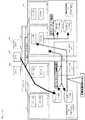
図1はストレージ装置の構成の一例を示したものである。
図1(a)は立体図、図1(b)は図1(a)のストレージ装置の断面図を示したものである。
ストレージ装置100は、HDD12、ファン13、電源ユニット14、コントローラ110、ホストポート15、ストレージ装置ポート16を有し、これらが筐体17によって覆われた構成となっている。なお、筐体17は、部品交換が容易にできないようにする構成とするもので、必ずしも密封状態とする必要はなく、他装置との接続部分、スイッチ等の操作部分、冷却のための空気口といった部分が存在する。このように容易に部品交換をできないようにすることで、例えば規定以外のHDDを誤って接続することを防止することができる。また、部品交換を前提としないことにより、部品配置の自由度が増加し、部品の搭載密度を従来よりも高くすることも可能となる。Hereinafter, it demonstrates using drawing.
In the first embodiment of the present invention, the storage apparatus includes a disk drive, a controller, a fan, and a power supply unit. As the disk drive, for example, a hard disk drive (hereinafter referred to as HDD), a DVD drive, or a magnetic tape drive can be adopted. Further, a flash memory can be employed instead of the disk drive.
Each component of the disk drive, controller, fan, and power supply unit can be configured to include alternative components. Replacement parts are those that do not operate until a failure occurs, start processing as a replacement for the failed component when a failure occurs, and operate even before the failure occurs and until the failure occurs after the failure occurs In addition to the processing performed in the above, both of the processing of the faulty component are included.
Specifically, a spare disk drive that operates in the event of a disk drive failure can be used as the former substitute part, and a duplicated controller, fan, and power supply unit can be used as the latter substitute part. A specific example of this configuration will be described below.
As a storage measure, a RAID (Redundant Array of Inexpensive Disks) technology is applied to set a plurality of LUs (Logical Units) on the storage area of the disk drive. An LU is a logical storage area set on a physical storage area of a disk drive, and can be provided to the host as a unit of storage area by the controller. A plurality of disk drives to which an LU is set by applying RAID are defined as a RAID group. When one of the disk drives constituting the RAID group fails, the data of the failed disk drive can be restored using the data of the other disk drives constituting the RAID group. This improves reliability against disk drive failures. The restored data is stored in the spare disk drive.
The storage device can be configured to include a first controller and a second controller. For example, when each of the first controller and the second controller is in charge of data transfer related to another LU, and the first controller and the second controller are not in trouble, the respective controllers are in charge. The data transfer to the LU to be controlled is controlled, and when a failure occurs in the first controller, the second controller controls the data transfer of both the LU in charge of the first controller and the LU in charge of the second LU. .
Similarly to the controller, the fan and the power supply unit can be configured to perform processing corresponding to the faulty component by another fan that has been operating until the time of the fault.
The above configuration is an example, and the disk drive is operated even before the latter, that is, before the occurrence of the failure, and after the failure occurs, the processing of the failed component is performed in addition to the processing performed until the failure occurs. The controller, the fan, and the power supply unit are replaced with the former replacement parts, that is, the parts that have not been operated until the time of the failure, and the processing is taken over as the replacement of the part that has failed when the failure occurs. You can also When the replacement part of the disk drive is used as the latter replacement part, the data stored in the failed disk drive is restored to the data non-storage area of the disk drive that has been operating before the failure after being restored by the RAID group. Will be stored.
<Appearance configuration>
FIG. 1 shows an example of the configuration of a storage apparatus.
1A is a three-dimensional view, and FIG. 1B is a cross-sectional view of the storage device of FIG. 1A.
The
図1(b)は、ストレージ装置の断面図であり、前面から後面に対して、コントローラ110、ファン13、HDD12、HDD12といった配列で基板の両面に実装した構成としている。ストレージ装置を小型化するために、HDD12を横置とし、更に、前面から後面に向かってHDDを2列に配置することで、容量を稼ぐ構成としている。
一方、図1(a)に示すように、HDDを横置きにし、X方向に4台ならべた配置とすると、これまで3.5インチHDDを縦置きでx方向に並べた標準的な寸法とほぼ一致させることができる。そのため、これまで利用していたストレージ装置を置くためのラックを同様に利用することができる。
また、ファン13についても、冷却効率の良い箇所に配置することができ、冷却効率を高めることができる。本ストレージ装置では、図1(b)に示すようにコントローラ110と、HDD12との間にファンを設ける構成とし、コントローラ110の熱をHDD側に送るようにしている。
なお、筐体17で覆うことにより防塵効果を得ることができ、各部品の障害発生確率を下げることも可能になる。電源ユニット14は、図1(a)に示すように2つの電源ユニット14を搭載している。この2つの電源ユニット14のうち、上側(プラスZ方向)に配置される電源ユニット14が、図1(b)に示す、基板10より上側にあるコントローラ110、ファン13、HDD12、に電力を供給し、下側(マイナスZ方向)に配置される電源ユニット14が、基板10の下側に配置されるコントローラ120、ファン13、HDD12に電力を供給する。また、2つの電源ユニット14は、それぞれ基板10の上側/下側両方の第1コントローラ110、ファン13、HDD12と接続されており、一方の電源ユニット14に障害が発生した際にはもう一方の電源ユニット14によって全てのコントローラ110、120、ファン13、HDD12に電力を供給する。電源ユニット14の配置は、図1(a)に示すように上下方向(z方向)に並べて配置する構成の他に、前後方向(x方向)に並べて配置することや図1(c)に示す配置してもよい。図1(a)及び図1(c)の配置とすることで、上側の部品配置と下側の部品配置とを対称となる構成となり、上下対称に配置されたファン13によって上下同様に冷却することができ、同じファンを採用した場合に冷却効率を向上させることができる。また、上下対象とすることで、設計、製造も容易になる。一方、電源ユニットの上下方向の寸法が3.5インチのHDD12を図1(a)のように2台上下並べた寸法と近く、前後方向(x方向)の寸法が一般的なコントローラ110の前後方向の半分の寸法に近い場合には、電源ユニット14を前後方向(x方向)にならべた配置を取ることで、ストレージ装置を小型化することができる。
<全体構成>
図2(a)は、ストレージ装置を利用したシステム全体の構成を示したものである。本システムは、ストレージ装置100、ホスト192a〜c、管理端末198、管理サーバ197とを有し、ストレージ装置100とホスト192a〜cが第1のネットワーク190、ストレージ装置100と管理端末198、管理サーバ197、ホスト192a〜cが第2のネットワーク191で接続されている。第1、第2のネットワークは、どのようなネットワークでも良い。例えば、SCSI、IPプロトコル等を利用したネットワークであってもよい。FIG. 1B is a cross-sectional view of the storage apparatus, which is configured to be mounted on both sides of the substrate in an array of a
On the other hand, as shown in FIG. 1A, when the HDDs are placed horizontally and arranged in a row in the X direction, the standard dimensions of 3.5 inch HDDs placed vertically in the x direction so far are as follows. Can be almost matched. Therefore, the rack for placing the storage device that has been used can be used in the same manner.
Moreover, the
In addition, a dustproof effect can be acquired by covering with the housing |
<Overall configuration>
FIG. 2A shows the configuration of the entire system using the storage apparatus. This system includes a
ストレージ装置100は、複数のコントローラ110、120、ディスクユニット165、構成要素管理部180a、180b、バックエンドインタフェース(I/F)部117、マスタ/スレーブ切替スイッチ185を有している。 The
ディスクユニット165は複数のディスクドライブ160を備えている。各ディスクドライブ160は、図示しないディスクと、半導体メモリ167とを有している。
コントローラ110、120は、いずれも同じ構成であり、ここではコントローラ110を例に説明する。コントローラ110は、ホスト192から送られてくる書込み又は読み出しといったアクセス要求に対して、ホスト192とディスクドライブ間のデータ転送を制御する。コントローラ110は、CPU112、複数のホストインタフェース(I/F)部114、116、ディスクインタフェース(I/F)部118、管理端末インタフェース部119並びにメモリ105を有し、これらが内部バス111を介して相互に通信可能に接続されている。ここでは、ストレージ装置100が2つのコントローラを有している構成を示しているが、1つのコントローラを有する構成であっても、あるいは3つ以上のコントローラを有する構成であってもよい。The disk unit 165 includes a plurality of disk drives 160. Each disk drive 160 has a disk (not shown) and a
The
CPU112は、メモリ105に格納されたプログラムを実行するものであり、これにより、ホストI/F部114、116、ディスクドライブ160、キャッシュ領域の間でのデータ転送を制御する。ここでは、1つのCPU112を有する構成を示しているが、複数のCPUを設けたものであってもよい。また、CPU112は、マルチコアといったように、CPUの中心となる処理部を複数有するものであっても良い。 The CPU 112 executes a program stored in the
ホストI/F部114、116は、いずれも、ネットワーク190と内部バス111とのインタフェースとして機能する。 Both the host I /
ディスクI/F部118は、データを記憶するディスクドライブ160と通信可能に接続されて内部バス111とディスクドライブ160のインタフェースとして機能し、ディスクドライブ160へのデータ入出力を制御する。
管理端末I/F部119は、ストレージ装置100と、管理端末198及びネットワーク191とのインタフェースとして機能する。
バックエンドインタフェース部117は、ディスクドライブ160と他のストレージ装置400とのインタフェースとして機能する。コントローラ110、120内に配置されずにディスクドライブと接続されることで、ストレージ装置100に障害が発生した場合に、構成情報170の読み出し、データ移行処理を実行することができる。
第1〜第3のホスト192a〜cは、ストレージ装置100を利用するホストである。第1〜第3のホスト192a〜cはスイッチを介してストレージ装置100に接続されても、スイッチを介さずにネットワーク190を介してストレージ装置100に接続されても、ネットワーク190を介さずに、直接ストレージ装置100に接続されても良い。
管理端末198は、例えばノート型パソコンにより構成され、論理ユニット作成やセキュリティの設定など、構成情報140の変更に関わる保守員の作業に必要なGUI(Graphical User Interface)やCLI(Common Line Interface)等のユーザインタフェースを提供する。
管理サーバ197は第1〜第3のホスト192a〜cとネットワーク191を介して通信可能に接続され、ホストに対する設定作業を行う。
図2(b)は、メモリ105が記憶する情報を示したものである。メモリ105には、プログラム130、ストレージ装置100の構成情報140、障害情報テーブル155が格納されている。メモリ105には更にホスト192とディスクドライブ160間で転送されるキャッシュデータ150を一時的に保存するためのキャッシュ領域が設けられる。The disk I /
The management terminal I /
The back
The first to
The
The
FIG. 2B shows information stored in the
プログラム130としては、ホスト192からのアクセス要求を処理する入出力処理プログラム132、構成情報140を管理する構成情報管理プログラム134、他のストレージ装置からデータ移行処理を実行するデータ移行プラグラム136等がある。
入出力処理プログラム132は、コントローラ110の基本機能を実行するためのプログラムであり、第1又は第2のホストインタフェース部114、116が受信したホスト192からのコマンドを解釈し、これが入出力に関するコマンドである場合には、このコマンドに応答するため、ディスクドライブ160に含まれる記憶媒体とキャッシュ領域との間のデータ転送や、キャッシュ領域とホスト192との間のデータ転送を実施する。
ホスト192からは、入出力要求の対象となるデータの格納場所が、LUN(Logical Unit Number。以下LU番号ともいう)と論理ブロックアドレス(LBA(logical Block Adress))の組で指定されるのに対して、ディスクドライブ160に対する入出力はディスクドライブの識別子と当該記憶媒体内のLBAで指定されるので、入出力処理プログラム132は構成情報140に含まれるLU構成テーブル142に基づいてアドレスを変換する処理を行い、データ格納先のディスクドライブにアクセスを実行する。
構成情報管理プログラム134は上述した図2に記載の構成情報140を構成する各テーブルの管理・更新を行うプログラムである。
データ移行プログラム136は、後述するデータ移行を実行するプログラムである。このデータ移行プログラム136は、ストレージ装置の交換が必要となった際に、利用していたストレージ装置内に記憶されているデータ/構成情報を取得して記憶する処理を実行する。
構成情報140は、LU構成テーブル142の他、ホスト接続モードパラメータテーブル144、実装ディスクドライブテーブル146、実装コントローラテーブル147、稼動ディスクドライブテーブル148、稼動コントローラテーブル149、ディスクドライブ管理テーブル141、ストレージ装置交換要否設定テーブル143等から構成される。Examples of the program 130 include an input /
The input /
From the host 192, the storage location of the data subject to the input / output request is specified by a combination of LUN (Logical Unit Number; also referred to as LU number) and logical block address (LBA (logical Block Address)). On the other hand, since the input / output to / from the disk drive 160 is specified by the identifier of the disk drive and the LBA in the storage medium, the input /
The configuration
The data migration program 136 is a program for executing data migration described later. The data migration program 136 executes a process of acquiring and storing data / configuration information stored in the storage apparatus that has been used when the storage apparatus needs to be replaced.
The configuration information 140 includes an LU configuration table 142, a host connection mode parameter table 144, a mounted disk drive table 146, a mounted controller table 147, an operating disk drive table 148, an operating controller table 149, a disk drive management table 141, and storage device replacement. It includes a necessity setting table 143 and the like.
複数のディスクドライブ160の中で、一部のディスクドライブ160はデータLU162と、データLU164との両方のLUを構成し、それ以外のディスクドライブ160はデータLU164を構成する。システムLU162は構成情報140のコピーである構成情報170、データ移行先/データ移行元を示すマスタ/スレーブ情報175を格納する。尚、マスタは、データ移行先ストレージ装置を示し、スレーブはデータ移行元ストレージ装置を示す。データLUはホスト192から送信されるデータ169を格納する。また、ディスクドライブ160は論理ドライブ番号168を記憶するメモリ167を備える。
構成要素管理部180は、基板10上に配置されるLSI、メモリ181から構成され、ディスクドライブ160の閉塞処理、電源ユニット14及びファン13の制御などの、ストレージ装置の構成要素の管理を行う。論理ドライブ番号については、図13−図15を用いて後述する。Among the plurality of disk drives 160, some of the disk drives 160 constitute both the
The component management unit 180 includes an LSI and a
図2(c)は、システムLU162が記憶する構成情報170を示したものである。構成情報170には、メモリ105に記憶される構成情報140の各テーブルのコピーが格納される。
次に、各種テーブルついて説明する。
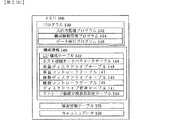
図3は、LU構成テーブルを示したものである。LU構成テーブル142には、LU毎に、LU番号、LUサイズ、RAIDグループ番号、LU設定順番、RAIDレベル、物理ドライブ番号が設定される。LU番号は、ストレージ装置100内のLUを一意に識別する番号である。LUサイズはLUの容量を示す。RAIDグループは、RAIDを構成するためにグループ化された複数のディスクドライブであり、RAIDグループ番号は、このグループに対して付された番号である。LU設定順番は、LUが設定された順番を示す。RAIDレベルは、各LUに適用されているRAIDレベルを示す。物理ドライブ番号は、各LUに記憶領域を提供しているディスクドライブの物理番号を示している。
図4は、ホスト接続モードパラメータテーブルを示したものである。コントローラ番号は第1コントローラ110と第2コントローラ120とを識別する番号である。ポート番号は、各コントローラの備えるホスト192a〜cと接続されるポートを識別する番号である。各ポート毎に、LUが割り当てられているかどうかを示すLU割当有無、割り当てられている場合にはLU番号が管理される。夫々ホストOS0、ホストOS1、…は各ポートが、どの種類のホストOSに対応するモードに設定されているかを示す。
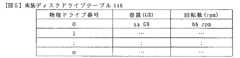
図5は、実装ディスクドライブテーブルを示したものである。実装ディスクドライブテーブル146は、ストレージ装置100に備えられている各ディスクドライブを識別する物理ドライブ番号、容量、回転数が設定される。
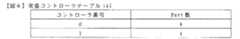
図6は、実装コントローラテーブルを示したものである。実装コントローラテーブル147は、第1コントローラ110(例えばコントローラ番号0)及び第2コントローラ(例えばコントローラ番号1)毎に、備えるポートの数が設定される。
図7は、ディスクドライブ管理テーブルを示したものである。ディスクドライブ管理テーブル141は、図5等にて管理されるディスクドライブの識別子である物理ドライブ番号と、コントローラ110及び120からアクセスする最に指定される論理ドライブ番号とを対応付けて設定される。ディスクドライブ管理テーブル141において、自装置物理ドライブ番号は自装置内の物理ドライブ番号/論理ドライブ番号の対応付けを管理しているものであり、他装置物理ドライブ番号は他のストレージ装置からのデータ移行時に使用する管理領域である。詳細は、図13―図15に示すストレージ装置間バックエンド接続処理にて説明する。
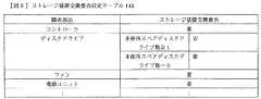
図8は、ストレージ装置交換要否設定テーブルを示したものである。ストレージ装置交換要否設定テーブル143は、ストレージ装置100を構成するコントローラ110及び120、ディスクドライブ160、スペアディスクドライブ、ファン、電源ユニットといった各部品に障害が発生した際に、動作継続するか、ストレージ装置の交換を行うかを各部品毎に設定する。尚、本実施例ではストレージ装置交換要否設定テーブル143にコントローラ、ディスクドライブ、スペアディスクドライブ、ファン、電源ユニット夫々に障害発生時にデータ移行要否を設定する例について記載しているが、例えばディスクドライブについてのみストレージ装置交換の要否を設定し、他の部品については管理せず、全てストレージ装置の交換を要とする例を取ることも可能である。
図9は、障害情報テーブル155を示したものである。
障害情報テーブル155は、コントローラ、ディスクドライブ、スペアディスクドライブ、ファン、電源ユニットの各部品の障害状況を設定するものである。障害が検出された際には、この障害情報テーブル155に検出された障害情報が追加される。図9では、第1コントローラ及び第2ディスクドライブに障害が発生しており、第1スペアディスクドライブが使用中であるとの状況を示している。
尚、稼動ディスクドライブテーブル148、稼動コントローラテーブル149については、図18、19を用いて後述する。
<ストレージ装置交換処理>
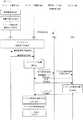
図10(a)−(c)は、本実施例におけるストレージ装置交換処理のイメージ図である。本実施例ではデータ移行元となるストレージ装置100(以降、移行元ストレージ装置ともいう)と、移行先となるストレージ装置400(以降、移行先ストレージともいう)が同じ構成のストレージ装置である場合について説明する。しかしながら、移行元ストレージ装置、移行先ストレージ装置の構成、性能が異なっていても、後述する処理が行えるCPUや、インタフェースを備えていれば、同じようにデータ移行を行うことが可能である。
ここでは、ストレージ装置100のコントローラ120に障害が発生した場合を例に説明する。図10(a)−(c)で示す処理内容は以下の通りである。(1)コントローラ120に障害が発生し、(2)コントローラ120からコントローラ110に引継ぎを行い、(3)コントローラ110がストレージ装置100の交換要否を要と判断し、(4)移行元ストレージ装置100と移行先ストレージ装置400との間でバックエンド接続を行い、(5)移行先ストレージ装置400のコントローラ410が移行元ストレージ装置100のシステムLUから構成情報を取得・格納し、(6)移行先ストレージ装置400が取得した構成情報を基にして移行先ストレージ装置400のLU(システムLU・データLU)に論理構成を設定し、(7)ホスト192のアクセス経路を移行元ストレージ装置から移行先ストレージ装置へと切り替え、(8)移行元ストレージ装置100のLUから論理構成の設定された移行先ストレージ装置400のLUにデータをコピーする。このように上記の処理では、移行先のストレージ装置400によって、移行元ストレージ装置100の構成情報を引継ぎ、論理構成の設定、更にデータコピーが行われるため、データ移行処理に掛かる保守員の負担を軽減させることができる。
尚、ホストアクセスに関しては、図10(a)−(c)で示す(2)の引継ぎ処理の後から(7)のアクセス経路切替処理の前までは、コントローラ110を介して、ディスクドライブ160から構成されるデータLU164に対して行われ、(7)のアクセス経路切替後は、コントローラ410を介して、ディスクドライブ160から構成されるデータLU164、ディスクドライブ460から構成されるデータLU464に行われる。
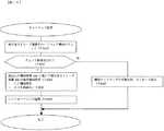
図11は図10(a)−(c)で示した、ストレージ装置に障害が発生した場合のストレージ装置交換処理の流れを示したものである。構成要素管理部180は、ディスクドライブ160、コントローラ110、120、ファン13、電源ユニット14等の部品の状態を監視し、状態に変化があった場合には障害と判断する。例えば、各部品から構成要素管理部180に対してハートビート信号を送るようにすれば、この信号が検知できなくなったときに障害と判断する。(S100)。
構成要素管理部180は障害と判断した場合に障害が発生した旨の通知をCPU112に行い、CPU112は当該障害に関する情報をメモリ105の障害情報テーブル155に設定する。尚、コントローラ110に障害が発生した場合には、コントローラ120のCPUに障害が発生した旨の通知が為され、当該障害に関する情報はコントローラ120内のメモリ125の障害情報テーブルに格納される。この際、構成要素管理部180は、部品に障害が発生したことを認識し、該障害が発生した部品の代替部品があれば、代替部品による引継ぎ処理を実行する。図10(a)に示すようにコントローラに障害が発生した場合には、処理を引き継ぐコントローラ及びホスト192との間で、ホストアクセス経路の切り替えが行われる(S200)。この後、ストレージ装置100のコントローラ110のCPU112(コントローラ110に障害が発生した場合においてはコントローラ120のCPU122)によって、ストレージ装置100での運用が継続可能か否かが判断される。運用が継続不可能と判断された場合には、他のストレージ装置による運用、つまり、ストレージ装置の交換が必要であることを意味する。(S300)。ストレージ装置交換が必要である場合には、コントローラ110若しくはコントローラ120から、管理サーバ197にその旨通知されて保守員に対して交換用のストレージ装置400の接続が促される。尚、管理サーバ197に代えて管理端末198に通知しても良い(S400)。通知にしたがってストレージ装置100とストレージ装置400が接続された後、バックエンド接続(S500)、ストレージ装置400による構成情報読み出し(S600、700)、セットアップ処理(S800)が実行される。セットアップ処理が完了した後は、移行先ストレージ装置400から管理サーバ197にセットアップが終了し、ホストからのIOコマンドの受領が可能である旨が通知され(S900)、S900通知の受領に基づいて管理サーバ197からホスト192に対してホストアクセス切替要求が送信される(S1000)。ホスト192からは、移行先ストレージ装置ストレージ装置400に対して接続確認コマンドが送信され(S1100)、移行先ストレージ装置400からの応答を受領すると(S1200)、アクセス経路の切替が行われる(S1300)。これでホスト192からIOコマンドが送信されるアクセス経路が移行元ストレージ装置100から移行先ストレージ装置400に切りかえられ、移行先ストレージ装置400にIOコマンドが送信される(S1400)。アクセス経路の切り替え後は、ストレージ装置400によって、アクセス経路切替後IO処理が実行される(S1500)。この後、ストレージ装置400によって、ストレージ装置100のデータをストレージ装置400にコピーするデータ移行処理が実行される(S1600)。尚、S1600のデータ移行処理は、S900−S1500の処理と平行して実行することも可能であるし、S900―S1500の処理の間に実行することも可能である。例えば、S800のセットアップ処理が終了した後、S900に代えてすぐにS1600の処理を実行しても良い。データ移行処理によって、ストレージ装置100のデータのコピーが完了した後に、ストレージ装置400がストレージ装置100のデータを削除するデータ消去処理が実行される(S1700)。
移行、S100〜S1700の処理について詳述する。先ず、S300のストレージ装置交換の要否判断処理について詳述する。FIG. 2C shows configuration information 170 stored in the
Next, various tables will be described.
FIG. 3 shows an LU configuration table. In the LU configuration table 142, an LU number, LU size, RAID group number, LU setting order, RAID level, and physical drive number are set for each LU. The LU number is a number that uniquely identifies an LU in the
FIG. 4 shows a host connection mode parameter table. The controller number is a number for identifying the
FIG. 5 shows a mounted disk drive table. In the mounted disk drive table 146, a physical drive number, a capacity, and a rotational speed for identifying each disk drive provided in the
FIG. 6 shows the mounting controller table. In the mounting controller table 147, the number of ports provided is set for each of the first controller 110 (for example, controller number 0) and the second controller (for example, controller number 1).
FIG. 7 shows a disk drive management table. The disk drive management table 141 is set in association with the physical drive number, which is the identifier of the disk drive managed in FIG. 5 and the like, and the logical drive number specified at the time of access from the
FIG. 8 shows a storage apparatus replacement necessity setting table. The storage device replacement necessity setting table 143 indicates whether the operation is continued when a failure occurs in each component such as the
FIG. 9 shows the failure information table 155.
The failure information table 155 sets the failure status of each component of the controller, disk drive, spare disk drive, fan, and power supply unit. When a failure is detected, the detected failure information is added to the failure information table 155. FIG. 9 shows a situation in which a failure has occurred in the first controller and the second disk drive, and the first spare disk drive is in use.
The operation disk drive table 148 and the operation controller table 149 will be described later with reference to FIGS.
<Storage device replacement processing>
FIGS. 10A to 10C are image diagrams of the storage device replacement processing in this embodiment. In the present embodiment, a case where the
Here, a case where a failure occurs in the controller 120 of the
Regarding host access, from the takeover process (2) shown in FIGS. 10A to 10C to the access path switching process (7) from the disk drive 160 via the
FIG. 11 shows the flow of the storage device replacement process when a failure occurs in the storage device shown in FIGS. 10 (a)-(c). The component management unit 180 monitors the status of components such as the disk drive 160, the
If the component management unit 180 determines that a failure has occurred, the component management unit 180 notifies the CPU 112 that a failure has occurred, and the CPU 112 sets information regarding the failure in the failure information table 155 of the
The process of migration and S100 to S1700 will be described in detail. First, the storage device replacement necessity determination process in S300 will be described in detail.
<ストレージ装置交換の要否判断>
図12はストレージ装置交換の要否判断の処理の詳細を示したものである。S300のストレージ装置交換の要否判断では、先ず、障害情報テーブル155とストレージ装置交換要否設定テーブル143とに基づいて、ストレージ装置100での運用が継続可能かが判断される(コントローラ110に障害が発生した場合においてはコントローラ120のCPU122によって、メモリ125内の障害情報テーブルとストレージ装置交換要否設定テーブルとに基づいて、ストレージ装置100での運用が継続可能かどうかが判断される)。
図9の障害情報テーブル155と、図8のストレージ装置交換要否設定テーブル143より、コントローラ120に障害が発生しているので、ストレージ装置交換は必要と判断される(S310)。図9、図8の情報によってコントローラ120に障害が発生したため、ストレージ装置交換が必要と判断された場合にはコントローラ110のCPU122は、ストレージ装置の交換においてストレージ装置100がデータの移行元となる様にシステムLU162内のマスタ/スレーブ情報175に“スレーブ”と設定する。これによって、ストレージ装置100はデータ移行元のストレージ装置となり、ストレージ装置400と接続された際に、データ移行先のストレージ装置が行う処理を実行することがなくなる(S320)。
S320の処理が終わると、S300のバックエンド接続処理は完了する。この後、ストレージ装置の交換が必要であれば、管理サーバ197にその旨通知された後、S500のっ句エンド接続処理(S500)が実行される。以下、S500のバックエンド接続処理について詳述する。
<バックエンド接続処理>
図13はバックエンド接続処理の詳細を示したものである。S500のバックエンド接続処理は図11のフローで示したS400での通知に従って保守員によってストレージ装置100とストレージ装置400とが接続されたことを、ストレージ装置400のコントローラ410のCPU412が検出する。この検出は、例えば、保守員によって移行先ストレージ装置400にインタフェースケーブル80が接続された後にバックエンドインタフェースケーブル417が接続先に対して信号を送信し、インタフェースケーブル80が移行元ストレージ装置100のバックエンドインタフェース部117と接続されることで応答が返ってきた場合に、その旨CPU412に報告することで、ストレージ装置100とストレージ装置400とが接続したことを検出することとすれば良い(S510a)。S510aと同様の処理が、移行元ストレージ装置100でも行われて、CPU112によってバックエンド接続が検出される(S510b)。S510bの処理は、移行元ストレージ装置100と移行先ストレージ装置400とが同じ構成をとっている場合に、バックエンド接続によって移行元ストレージ装置100にも発生する処理である。
移行先ストレージ装置400のCPU412はS510の検出の後、システムLU462のマスタ/スレーブ情報に“スレーブ”と設定されていない場合に “マスタ”と設定する。移行元ストレージ装置100のCPU112は、S320にて“スレーブ”と設定されているため、バックエンド接続を検出しても“マスタ”と設定しない(S520)。
この後、設定確認処理が行われる。ストレージ装置100、400は手動で切り替えるマスタ/スレーブ切り替えスイッチを備えており、保守員によってストレージ装置100のマスタ/スレーブ切り替えスイッチは“スレーブ”に、ストレージ装置400のマスタ/スレーブ切り替えスイッチは“マスタ”に切りかえられてから、インタフェースケーブル80によってストレージ装置100とストレージ装置400とが接続される。S520のマスタ設定処理の後、CPU412は、バックエンドインタフェース417を介してマスタ/スレーブ切り替えスイッチの切り替えと、S520で設定したシステムLU462のマスタ/スレーブ情報とを比較し、一致していない場合には管理端末198に通知して保守員がマスタ/スレーブの切り替えスイッチの切り替えを確認するように表示させる(S525a)。このマスタ/スレーブの設定は誤って設定するとデータを失う危険性があるため、S320及びS520の処理と、マスタ/スレーブ切り替えスイッチによる手動の切り替えとで二重チェックする仕組みとなっている。尚、S520においてシステムLU462のマスタ/スレーブ情報に“スレーブ”と設定されていない場合に“マスタ”と設定するようにする他、CPU412がストレージ装置400のメモリ405及び425内の構成情報を参照し、例えばLU設定テーブルについて、設定されている情報がない場合に “マスタ”と設定するようにしても良い。<Determining if storage device needs to be replaced>
FIG. 12 shows the details of the processing for determining whether or not the storage device needs to be replaced. In determining whether or not the storage device needs to be replaced in S300, first, based on the failure information table 155 and the storage device replacement necessity setting table 143, it is determined whether or not the operation in the
From the failure information table 155 in FIG. 9 and the storage device replacement necessity setting table 143 in FIG. 8, it is determined that the storage device needs to be replaced because a failure has occurred in the controller 120 (S310). When the controller 120 has failed due to the information in FIGS. 9 and 8, and it is determined that the storage device needs to be replaced, the CPU 122 of the
When the process of S320 ends, the back-end connection process of S300 is completed. Thereafter, if the storage apparatus needs to be replaced, the
<Backend connection processing>
FIG. 13 shows the details of the back-end connection processing. In the back-end connection process of S500, the CPU 412 of the controller 410 of the
After the detection of S510, the CPU 412 of the migration
Thereafter, a setting confirmation process is performed. The
次に、マスタに設定されている移行先ストレージ装置400内の構成要素管理部480は、バックエンドインタフェース部117、417、及びインタフェースケーブル80から成るバックエンドインタフェース上に障害が発生していないかどうかをチェックする(S530)。チェックの結果障害が発生していない場合には、構成要素管理部480がその旨を、スレーブに設定されている移行元ストレージ装置100内の構成要素管理部180に通知する(S535)。通知を受領した後、構成要素管理部180は、移行元ストレージ装置100の各ディスクドライブ160のメモリ167の論理ドライブ番号168をスレーブ設定時のものに変更する(S540)。論理ドライブ番号168は、ディスクドライブ160にディスクインタフェース部118からアクセスする際に、ディスクドライブ160を識別する為の識別子である。各ディスクドライブ160がFCループ(Fibre Channel loop)で接続された構成をとる場合には、ディスクインタフェース部118は、ループ番号及び論理ドライブ番号を指定してアクセスする。
S540の処理の後、各ディスクドライブ160の論理ドライブ番号を管理する構成要素管理部180内のメモリ181のディスクドライブ管理テーブル182が、S540の変更内容に更新される。この後、構成要素管理部180は、CPU112に通知してコントローラ110内のメモリ105のディスクドライブ管理テーブル141をディスクドライブ管理テーブル182と同じ内容に更新する(S550)。
また、S550の処理の後に構成要素管理部180は、構成要素管理部480に移行元ストレージ装置100の各ディスクドライブ160の論理ドライブ番号を変更した旨を通知した後(S555)、更新後のメモリ181内のディスクドライブ管理テーブル182を提供する。構成要素管理部480、CPU412及び422は、更新後のディスクドライブ管理テーブル182から各ディスクドライブ160の変更後の論理ドライブ番号を取得して、メモリ481、405及び425のディスクドライブ管理テーブルを更新する(S560)。このS540−S560の処理(以降、スレーブのディスクドライブ論理番号変更処理という)における、論理デバイス番号168の変更及びディスクドライブ管理テーブルの変更について図14、図15(a)、(b)にて示す。
<スレーブのディスクドライブ論理番号変更処理>
図14は、ディスクドライブ160の論理ドライブ番号168の変更前と変更後のイメージを示したブロック図である。
図13のフローS540において、スレーブである移行元ストレージ装置100の構成要素管理部180は、図14に示す様に、各ディスクドライブ160のメモリ167の論理ドライブ番号168を変更する。具体的には、「0」「1」…などの数値で表されていたものを、「A」「B」…などのアルファベットの表現に変更する。この変更によって、マスタである移行先ストレージ装置400のディスクドライブの論理デバイス番号と、スレーブである移行元ストレージ装置100のディスクドライブの論理デバイス番号とが重複することがなくなる。この変更によって、マスタである移行先ストレージ装置400のコントローラ410、420は、各ディスクドライブ160、460の両方のディスクドライブを一意に指定してアクセスすることが可能となる。Next, the component management unit 480 in the migration
After the process of S540, the disk drive management table 182 of the
After the processing of S550, the component management unit 180 notifies the component management unit 480 that the logical drive number of each disk drive 160 of the migration
<Slave disk drive logical number change processing>
FIG. 14 is a block diagram showing images before and after the
In the flow S540 of FIG. 13, the component management unit 180 of the migration
図15(a)は、マスタである移行先ストレージ装置400のメモリ405、425、481内の、変更後のディスクドライブ管理テーブルを示したものである。図15(b)は、スレーブである移行元ストレージ装置100のメモリ105、181内の、変更後のディスクドライブ管理テーブルを示したものである。S550、S560の処理によって図15の様に変更される。尚、本実施例においてはコントローラ120に障害が発生した例について説明しているため、コントローラ120のメモリ125について述べていないが、ストレージ装置100において他の部品に障害が発生した場合にはメモリ125内のディスクドライブ管理テーブルも変更される。マスタである移行先ストレージ装置400は、図15(a)に示すテーブルを用いて、ディスクドライブ160と460との両方のディスクドライブにアクセスし、スレーブである移行元ストレージ装置100は図15(b)に示すディスクドライブ管理テーブルを用いて、ディスクドライブ160にアクセスする。 FIG. 15A shows the disk drive management table after the change in the
このS540−S560後、CPU412は管理端末にバックエンド接続が成功した旨をメッセージ表示し、バックエンド接続処理S500が完了する(S570)。
上述した処理によって、バックエンド接続処理S500が完了した後は、図11のフローで示した、S600−S700の処理(以降、構成情報参照処理という)が実行される。
以降、構成情報参照処理について詳述する。
<構成情報参照処理>
移行先ストレージ装置400のCPU412は移行元ストレージ装置100のディスクドライブ160のうち、システムLU162を構成するディスクドライブにアクセスし、移行元ストレージ装置100の構成情報170を読み出す(S600、S700)。移行元ストレージ装置100の構成情報170は、例えば、システムLU162を構成する5台のディスクドライブの所定の領域に5重に記憶された構成とすることができる。この5台のディスクドライブ160のスレーブ設定時の論理ドライブ番号と、構成情報170が格納された所定の領域とは予めコントローラ410内のメモリ405内のデータ移行プログラムに設定されており、CPU412は移行元ストレージ装置のシステムLUを構成するディスクドライブにアクセスして構成情報170を読みだし、取得することができる。これによって構成情報参照処理が完了する。After this S540-S560, the CPU 412 displays a message to the effect that the back-end connection is successful on the management terminal, and the back-end connection process S500 is completed (S570).
After the back-end connection processing S500 is completed by the above-described processing, the processing of S600 to S700 (hereinafter referred to as configuration information reference processing) shown in the flow of FIG. 11 is executed.
Hereinafter, the configuration information reference process will be described in detail.
<Configuration information reference processing>
The CPU 412 of the migration
読み出される構成情報170は、図2(c)に示す、LU構成情報テーブル172、ホスト接続モードパラメータテーブル174、実装ディスクドライブテーブル176、実装コントローラテーブル177、稼動ディスクドライブテーブル178、稼動コントローラテーブル179、ストレージ装置交換要費設定テーブル173である。 The read configuration information 170 includes an LU configuration information table 172, a host connection mode parameter table 174, a mounted disk drive table 176, a mounted controller table 177, an operating disk drive table 178, an operating controller table 179, as shown in FIG. This is a storage device replacement cost setting table 173.
上述のように、構成情報参照処理S600−S700が完了した後は、図11のフローで示した、S800のセットアップ処理が実行される。以降、セットアップ処理について詳述する。
<セットアップ実施>
図16は、セットアップ処理を示したものである。コントローラ410は、S700で取得した移行元ストレージ装置100の構成情報170と移行先ストレージ装置400の構成情報440とを比較し、移行先ストレージ装置が移行元ストレージ装置の移行先として十分なハードウェア構成を有しているか否かをチェックし、十分なハードウェア構成を有している場合にはCPU412は、ストレージ装置400を移行先のデータストレージ装置として適切なものとし、チェック結果を“OK”に設定する。(S810)。S810の移行先ストレージ装置のハードウェア構成のチェック処理は、図17(a)−(c)を用いて後述する。
このS810のチェックの結果がOKであれば、(S820でY)ストレージ装置400をストレージ装置100の処理の引き継ぎ先とし、S700で取得した構成情報140を基にして、ストレージ装置400に論理構成を設定する。論理構成設定においては、LU構成テーブル172、ホスト接続モードパラメータテーブル174を使用して、ストレージ装置400に、ストレージ装置100と同じように、RAID構成を含んだLU構成の設定、各LUと各Portとの論理経路設定、コントローラの各ホスト192(a)−(c)毎のモード設定が行われる(S830)。この後、移行先ストレージ装置400のLUフォーマット起動処理が行われる。この、LUフォーマット起動処理はS830の処理完了後、自動的に実施される。(S840)。一方、S830のチェックで、チェック結果が“NG”だった場合には、管理端末にエラーメッセージにてその旨を通知する(S850)。これによって、セットアップ処理S800が完了する。このセットアップ処理S800の一部の処理である移行先ストレージ装置のハードウェア構成のチェック処理S810について、以下詳述する。
<移行先ストレージ装置のハードウェア構成のチェック処理>
図17(a)は、移行先ストレージ装置のハードウェア構成のチェック処理について示したものである。このチェック処理は、上述のようにストレージ装置400が、ストレージ装置100のデータ移行先として十分なハードウェア構成を備えているかを判断するためのものである。先ず、移行先ストレージ装置400のハードウェア構成を移行元ストレージ装置100の全てのハードウェア構成と比較するか否かを判断する(S811)。このS811の処理では、移行先ストレージ装置400のハードウェア構成のスペックが障害発生前のストレージ装置100において稼動していたハードウェア構成のスペック以上であればストレージ装置の引継ぎ先として良いか、それとも移行先ストレージ装置400のハードウェア構成のスペックが、移行元ストレージ装置100において稼動していたディスクドライブ/コントローラ/ポート等のハードウェアも障害発生前に稼動していなかったハードウェアも含めた全てのハードウェア構成のスペック以上でなければ、ストレージ装置の引継ぎ先としては不十分とするか、を設定する。
移行元ストレージ装置100と移行先ストレージ装置400とのハードウェア構成のスペックの比較は、S700にて移行先ストレージ装置400が取得した構成情報170の中の、実装ディスクドライブテーブル176、実装コントローラテーブル177、稼動ディスクドライブテーブル178、稼動コントローラテーブル179の各テーブルと、メモリ405に設定されている移行先ストレージ装置400の対応する各テーブル(移行先ストレージ装置400の対応する各テーブルを実装ディスクドライブテーブル446、実装コントローラテーブル447、稼動ディスクドライブテーブル448、稼動コントローラテーブル449とする)とに基づいて、ディスクディスクドライブの数、容量、コントローラの数、ポートの数等の各値を比較することで行われる。
この判断は、CPU412から、管理端末に問い合わせをメッセージ表示して、保守員から得た回答に基づいても良いし、ストレージ装置400とストレージ装置100との接続前に、予め管理端末からメモリ405、425に設定しておいても良い。S811にて、YESと判断されると、図17(b)にて示す移行元ストレージ装置100の全ハードウェア構成と、移行先ストレージ装置400のハードウェア構成との比較処理(S812)が実行される。一方、S811にて、NOと判断されると、図17(c)にて示す移行元ストレージ装置100の稼動ハードウェア構成と移行先ストレージ装置400のハードウェア構成との比較処理 (S813)が実行される。これによって、移行先ストレージ装置のハードウェア構成のチェック処理S810の処理が完了する。次に、移行先ストレージ装置のハードウェア構成のチェック処理S810の一部の処理である移行元ストレージ装置100の全ハードウェア構成と移行先ストレージ装置400のハードウェア構成との比較処理S812について、詳述する。
図17(b)は、移行元ストレージ装置100の全ハードウェア構成と、移行先ストレージ装置400のハードウェア構成との比較処理S812を示したものである。
S812の処理は、ストレージ装置400に読み出された移行元ストレージ装置100の実装ディスクドライブテーブル176及び実装コントローラテーブル177と、移行先ストレージ装置の実装ディスクドライブテーブルと実装コントローラテーブルとを比較することで為される。本処理では図5に示す内容の実装ディスクドライブテーブル176及び446のディスクドライブの数(物理ドライブ番号から比較)及び各ディスクドライブの容量、図6に示す内容の実装コントローラテーブル177及び447のコントローラ数(コントローラ番号から比較)、各コントローラにおけるport数のそれぞれについて比較し、実装ディスクドライブテーブル446のディスクドライブ数(物理ドライブ番号)、各ディスクドライブの容量、実装コントローラテーブル447のコントローラ数(コントローラ番号)、各コントローラのport数、の全ての要素が移行元ストレージ装置100の実装ディスク装置テーブル176、実装コントローラテーブル177以上であれば、チェック結果を“OK”とし、そうでなければチェック結果を“NG”とする。以下CPU412の処理について具体的に説明する。
先ず、ディスクドライブ数について比較する(S812−1)。先ず、実装ディスクドライブテーブル446のディスクドライブの数が実装ディスクドライブテーブル176のドライブ数よりも少ない場合にはNと判断され、そうでない場合にはYと判断される。
次に、ディスクドライブ容量について比較する(S812−2)。実装ディスクドライブテーブル446のドライブ数が実装ディスクドライブテーブル176のドライブ数以上の場合には、実装ディスク装置テーブル446と実装ディスク装置テーブル146との各ドライブとの対応付けにおいて、ドライブの容量が、実装ディスク装置テーブル446のドライブが実装ディスクドライブテーブル176のドライブ以上となるように対応付けられる場合にはディスクドライブについてYと判断しこのように対応付けられない場合にはNと判断する。
S812−2の処理の次に、コントローラ数について比較する(S812−3)。
ディスクドライブについてYと判断された場合には、引き続いて実装コントローラテーブル447と実装コントローラテーブル177との比較作業が行われる。
実装コントローラテーブル177と実装コントローラテーブル447との比較作業においては、それぞれのテーブルのコントローラ数(コントローラ番号)の大小を比較し、実装コントローラテーブル447のコントローラ数が実装コントローラテーブル177のコントローラ数よりも少ない場合には、Nと判断される。そうでない場合にはYと判断される。
次にポート数について比較する(S812−4)。
実装コントローラテーブル447のコントローラ数が実装コントローラテーブル177のコントローラ数以上である場合には引き続いて実装コントローラテーブル447と実装コントローラテーブル177との各コントローラとの対応付けにおいて、実装コントローラテーブル447のコントローラのport数が実装コントローラテーブル177のコントローラのport数以上となるように対応付けられる場合にはコントローラのPort数についてYと判断し、このように対応付けられない場合にはNと判断する。
S812−4でもYと判断された場合、S812−5にて、CPU812はチェック結果を”OK”とする。一方、S812−1〜S812−4にて、Nと判断した場合には、チェック結果を”NG”とする。
尚、ディスクドライブの容量のみならずディスクドライブの回転数を判断のパラメータとしてこのS812−1〜S812−4の処理に加えても良い。この場合、ストレージ装置400のディスクドライブについて、ディスクドライブ数及びディスクドライブ容量及びディスクドライブの回転数がストレージ装置100を上回っている場合にのみ、Yと判断される。この場合、実装ドライブテーブル446と実装ドライブテーブル176との各ドライブの対応付けにおいて、ディスクドライブの容量及びディスクドライブの回転数ともに、実装ドライブテーブル446のドライブが実装ドライブテーブル176のドライブ以上となる組み合わせが存在するかどうかを確認し、存在する場合にはドライブについてYと判断し、存在しない場合にはNと判断する。これによって、移行元ストレージ装置100の全ハードウェア構成と移行先ストレージ装置400のハードウェア構成との比較処理S812が完了する。次に、移行先ストレージ装置400のハードウェア構成を移行元ストレージ装置100の全てのハードウェア構成と比較するかの判断処理S811にてNOと判断された場合の、移行元ストレージ装置100の稼動ハードウェア構成と移行先ストレージ装置400のハードウェア構成との比較処理 (S813)について詳述する。
図17(c)は、移行元ストレージ装置100の稼動ハードウェア構成と、移行先ストレージ装置400のハードウェア構成との比較処理S813を示したものである。
S813の処理においては、LU構成テーブル142及びホスト接続モードパラメータ設定テーブル144、実装ドライブテーブル146を元に設定されているテーブルである、図19に示す内容の稼動ディスクドライブテーブル178、図20に示す稼動コントローラテーブル179を用いて、比較処理がなされる。稼動ディスクドライブテーブル178のLUへの割当量は、LU構成テーブルのLU容量及びRAIDレベルから算出される。S813−1〜S813−4の処理においては、ディスクドライブについては、上述したS812−1〜S812−4の処理における実装ドライブテーブル176の代わりに稼動ディスクドライブテーブル178と、ストレージ装置400の実装ディスクドライブテーブル446とを比較する処理を行う。この稼動ディスクドライブテーブル148と実装ディスクドライブテーブル446との比較処理においては、稼動ディスクドライブテーブル148の、ドライブ番号と割当容量(回転数)について、S812にて行った実装ディスクドライブテーブル176と実装ディスクドライブテーブル446との比較処理と同様の処理を行う。コントローラ及びコントローラに備えられるport数についても実装コントローラテーブル177と実装コントローラテーブル447の比較処理と同様に、稼動コントローラテーブル179と実装コントローラテーブル447との比較処理を行う。この、S813−1〜S813−4の処理にて、Yと判断された場合には、チェック結果を“OK”とし(S813−5)、Nと判断された場合には、チェック結果を“NG”とする(S813−6)。
上述の処理によって、移行先ストレージ装置400は、移行元ストレージ装置100の移行先として十分なハードウェア構成を備えているかどうかのチェックS810の処理が終了する。As described above, after the configuration information reference processing S600 to S700 is completed, the setup processing of S800 shown in the flow of FIG. 11 is executed. Hereinafter, the setup process will be described in detail.
<Setup execution>
FIG. 16 shows the setup process. The controller 410 compares the configuration information 170 of the migration
If the result of the check in S810 is OK (Y in S820), the
<Hardware configuration check processing of migration destination storage device>
FIG. 17A shows the hardware configuration check process of the migration destination storage apparatus. This check process is for determining whether the
The comparison of the hardware configuration specifications between the migration
This determination may be based on an answer obtained from the maintenance staff by displaying a message from the CPU 412 to the management terminal, or before the connection between the
FIG. 17B shows a comparison process S812 between the entire hardware configuration of the migration
The processing of S812 is performed by comparing the mounted disk drive table 176 and mounted controller table 177 of the migration
First, the number of disk drives is compared (S812-1). First, when the number of disk drives in the mounted disk drive table 446 is smaller than the number of drives in the mounted disk drive table 176, it is determined as N, and otherwise it is determined as Y.
Next, the disk drive capacities are compared (S812-2). If the number of drives in the mounted disk drive table 446 is equal to or greater than the number of drives in the mounted disk drive table 176, the drive capacity is determined by the mounting disk device table 446 and the mounted disk device table 146 in association with each drive. When the drive of the disk device table 446 is associated so as to be equal to or greater than the drive of the mounted disk drive table 176, it is determined that the disk drive is Y, and when it is not correlated in this way, it is determined N.
Following the processing of S812-2, the number of controllers is compared (S812-3).
If it is determined that the disk drive is Y, then the mounting controller table 447 and the mounting controller table 177 are compared.
In the comparison work between the mounting controller table 177 and the mounting controller table 447, the number of controllers (controller numbers) in each table is compared, and the number of controllers in the mounting controller table 447 is smaller than the number of controllers in the mounting controller table 177. In this case, it is determined as N. Otherwise, it is determined as Y.
Next, the number of ports is compared (S812-4).
When the number of controllers in the mounted controller table 447 is equal to or greater than the number of controllers in the mounted controller table 177, the controller port of the mounted controller table 447 is subsequently associated with each controller in the mounted controller table 447 and the mounted controller table 177. If the number is associated with the number of controller ports in the mounted controller table 177, the controller port number is determined to be Y. If the number is not correlated in this way, N is determined.
If it is also determined as Y in S812-4, the CPU 812 sets the check result to “OK” in S812-5. On the other hand, if it is determined as N in S812-1 to S812-4, the check result is “NG”.
Note that not only the capacity of the disk drive but also the rotational speed of the disk drive may be added to the processing of S812-1 to S812-4 as a determination parameter. In this case, regarding the disk drive of the
FIG. 17C shows a comparison process S813 between the operating hardware configuration of the migration
In the process of S813, the active disk drive table 178 having the contents shown in FIG. 19 and the table shown in FIG. 20 are set based on the LU configuration table 142, the host connection mode parameter setting table 144, and the mounted drive table 146. Comparison processing is performed using the operation controller table 179. The allocation amount of the active disk drive table 178 to the LU is calculated from the LU capacity and RAID level of the LU configuration table. In the processing of S813-1 to S813-4, for the disk drive, the active disk drive table 178 and the mounted disk drive of the
With the above-described processing, the migration
なお、本実施例では、障害発生前のストレージ装置100の稼動状況に拠らずに、移行先ストレージ装置400のハードウェア構成のスペックが、移行元ストレージ装置100のハードウェア構成のスペック以上であるか否か(ハードディスクの数、容量、コントローラの数、コントローラの備えるポート数といった各数値が移行先ストレージ装置400が移行元ストレージ装置100と同じ若しくは上回っているか否か)についての比較処理(S812)と、移行先ストレージ装置400のハードウェア構成のスペックが、障害発生前に移行元ストレージ装置100にて稼動していたハードウェア構成のスペック以上であるか否かについての比較処理(S813)とのいずれか、一方を選択する例について記載したが、先ず、S812の比較処理を行い、S812の比較処理の結果、“NG”となった場合に、S813で“OK”ならばストレージ装置400を移行先ストレージとして良いか否か保守員に問い合わせを行った上で、S813を開始することとしても良い。 In this embodiment, the specification of the hardware configuration of the migration
以上、セットアップ処理S800について詳述した。セットアップ処理S800が完了した後、移行先ストレージ装置400のCPU412は、管理サーバ197にセットアップが終了し、ホストからのアクセスが受領可能である旨の通知を送信する(S900)。通知を受信すると、管理サーバ197は管理している移行元ストレージ装置100のホストポートのWWN(World Wide Name:ネットワーク上でポートを一意に識別する識別子)及び、移行先ストレージ装置のホストポートのWWNとを対応付けてホスト192に通知し、ホスト192の備えるアクセス経路切替アプリケーションに、移行元ストレージ装置100から移行先ストレージ装置400へのアクセス経路の切替を促す(S1000)。ホスト192のアクセス経路切替アプリケーションは、管理サーバ192から送信された移行元ストレージ装置100のホストポートと対応付けられた移行先ストレージ装置400のホストポートのWWNを認識した後、接続が可能であるかを確認するために認識したWWNを指定してネットワーク190を介して移行先ストレージ装置400に接続確認コマンドを送信する(S1100)。これに対して、ストレージ装置400が応答することで(S1200)、アクセス経路切替アプリケーションによって、アクセス経路の切替が実行される(S1300)。
尚、S900−S1300の処理は、管理サーバ197及びホスト192内のアクセス経路アプリケーションを用いることなく、以下の方法で行うこともできる。S800のセットアップ処理が終了した後、移行先ストレージ装置400は管理端末に、セットアップ処理が終了して、ホストからのアクセス経路を受領可能である旨表示する。これを受けて、保守員が、ホスト192のIO処理を一旦中断して、アクセス経路の設定を入力作業を行う。入力作業において、アクセス経路が、移行元ストレージ装置100から移行先ストレージ装置に切替られ、この後IO処理が再開されるようにすれば良い。
この後、IOコマンドは、移行先ストレージ装置400に対して送信される(S1400)。この後、IOコマンドが移行先ストレージ装置400に対して送信されたときのストレージ装置400が実行するアクセス経路切替後IO処理S1500について、以下詳述する。
<アクセス経路切替後IO処理>
図20は、アクセス経路切替後のIO処理について示したものである。
移行先ディスクアレイ装置400は、切り替えられたアクセス経路を介して、ホスト192から送信されるIOコマンドを受領する(S1510)。CPU412は受領したIOコマンドを解析して、IOコマンドが読み出し要求であるか否かを判断する(S1520)。読み出し要求である場合には(S1520でY)、CPU412は、バックエンド接続インタフェース部417を介して、IOコマンドで指定されるLU番号(及びLBA)に従って移行元ストレージ装置100のデータLU164を構成するディスクドライブ160からデータを読み出し(S1530)、ホスト192に送信する(S1540)。
一方、受領したIOコマンドが読み出し要求でなく、書き込み要求である場合には(S1530でN)、CPU412は、IOコマンドで指定されるLU番号(及びLBA)にしたがって、自装置内のデータLU464を構成するディスクドライブ460に書き込み処理を行うとともに、バックエンドインタフェース417を介して移行元ストレージ装置100のデータLU164を構成するディスクドライブ160に書き込み処理を行う(S1550)。書き込み処理が完了したら、ホスト192に対して完了通知を行う(S1560)。
尚、図11のフローの説明にて記載したように、S1600のデータ移行処理はS900−S1500の間に実行することもできる。この前提において、S1530の読み出し処理について移行元ストレージ装置100のドライブから読み出しが行われる理由はストレージ装置間データ移行処理が既に為されたデータについての読み出し処理の場合には移行元ストレージ装置100、移行先ストレージ装置400のどちらのディスクドライブから読み出しても問題ないが、データ移行が未だ為されていないデータについての読み出し処理の場合には読み出し処理の要求するデータが移行先ストレージ装置400のディスクドライブ460には存在せず、移行元ストレージ装置100のディスクドライブ160にのみ存在するためである。
また、書き込み処理が移行元ストレージ装置100及び移行先ストレージ装置400の双方のディスクドライブに書き込まれる理由を下述する。移行元ストレージ装置のドライブに書き込まれる理由は、データ移行が完了されるまでの間、ホスト192からの読み出し処理はすべて移行元ストレージ装置のドライブに対して為されるため、ホスト192からの書き込みデータを反映している必要があるためである。また、移行先ストレージ装置400のディスクドライブ460についても書き込まれる理由は、データ移行処理が為されていないデータについての書き込み処理であれば、移行元ストレージ装置100のディスクドライブ160にのみ書き込み処理を行ったとしても、後に書き込み処理が反映されたデータが移行元ストレージ装置100のディスクドライブ160から移行先ディスクドライブ460にコピーされるので問題ないが、データ移行が既に為されたデータについては、移行先ストレージ装置400のディスクドライブ460に書き込まれない場合には書き込み処理が反映されたデータがコピーされない為、書き込み処理を反映したデータが移行先ストレージ装置400のディスクドライブに存在しない事態が生じる為である。上記の事態を避ける為に、書き込み処理については移行元ストレージ装置100、移行先ストレージ装置400の両方のドライブに書き込み処理が実行される。上述した様に、読み出し処理については移行元ストレージ装置100のディスクドライブから読み出しを行い、書き込み処理については移行元ストレージ装置100のディスクドライブ160及び移行先ストレージ装置400のディスクドライブ460の両方のドライブに書き込みを行うことで、データ移行処理S1600の進捗によることなく、ホスト192からの読み出し要求及び書き込み要求を、漏れなく処理することができる。
尚、例えばデータ移行の進捗を所定領域ごとに管理するビットマップをメモリ405内に備え、書き込み処理を移行先ディスクアレイ装置400のディスクドライブ460及び移行先ディスクアレイ装置100のディスクドライブ160の両方に行うことなく、データ移行済みであれば移行元ストレージ100と移行先ストレージ400との両方のドライブに書き込み、データ移行が未だなされていない領域への書き込み処理であれば移行元ストレージ装置100のディスクドライブ160にのみ書き込む構成とすることもできる。この場合、ストレージ装置間データ移行の進捗を管理する必要が生じるが、ストレージ装置400におけるホストIO処理にかかる処理負担を軽減することができる。
以上、アクセス経路切り替え後IO処理S1500について詳述した。続いて、アクセス経路切り替え後IO処理1500の後若しくはS900―S1500の処理の間に実行されるデータ移行処理S1600について詳述する。
<データ移行処理>
図21は、データ移行処理を示すものである。The setup process S800 has been described in detail above. After the setup process S800 is completed, the CPU 412 of the migration
Note that the processing of S900 to S1300 can also be performed by the following method without using the access path application in the
Thereafter, the IO command is transmitted to the migration destination storage apparatus 400 (S1400). Thereafter, the post-access path switching IO processing S1500 executed by the
<IO processing after switching access path>
FIG. 20 shows the IO processing after switching the access path.
The migration destination
On the other hand, if the received IO command is not a read request but a write request (N in S 1530), the CPU 412 stores the data LU 464 in its own device according to the LU number (and LBA) specified by the IO command. Write processing is performed on the disk drive 460 constituting the disk drive, and write processing is performed on the disk drive 160 constituting the
Note that, as described in the description of the flow in FIG. 11, the data migration processing in S1600 can also be executed between S900 and S1500. Under this premise, the reason for reading from the drive of the migration
The reason why the write process is written to the disk drives of both the migration
For example, a bitmap that manages the progress of data migration for each predetermined area is provided in the
The IO processing S1500 after switching the access path has been described in detail above. Next, the data migration processing S1600 executed after the IO processing 1500 after switching the access path or during the processing of S900 to S1500 will be described in detail.
<Data migration processing>
FIG. 21 shows the data migration process.
移行先ストレージ装置400のCPU412は、S700で取得した構成情報170のLU管理テーブルを元にデータコピーを行うデータLU162を特定し、当該データLU162を構成するディスクドライブ160の物理ドライブ番号を特定する。この後、セットアップ処理S830の論理設定において当該LUに対応して論理設定した移行先ストレージ装置400のLUを構成するディスクドライブの物理ドライブ番号を特定する。(S1610,S1620)。この後、メモリ105内のディスクドライブ管理テーブルに基づいて、当該ディスクドライブ160、460の論理ドライブ番号を特定する(S1630)。この後、ディスクドライブ160からデータを読み出し、ディスクドライブ460にデータを書き込む(SS1630、S1640)。このS1610−S1640の処理を、全てのLUが完了するまで実行し、全てのLUが完了したらデータ移行処理が完了する。 The CPU 412 of the migration
尚、例えば、ディスクドライブ160の障害によって、RAIDグループによるコレクションコピーが必要な状況で、本データ移行処理が行われる場合には、ディスクドライブ160からデータを読み出して、コレクションコピーによってデータを復旧して、ディスクドライブ460に格納することもできる。
S1600の処理完了を認識すると、移行先ストレージ装置400のCPU412は移行元ストレージ装置100の全ディスクドライブ160のデータを消去する。これは、移行元ストレージ装置100が、ストレージ装置間処理完了時に、廃棄若しくは回収される場合に、データ漏洩が発生する危険を回避するためである。
以上、説明したように、本発明によれば、ディスクドライブ、コントローラ、ファン、電源ユニットといった各部品及び各部品の代替部品を備えるストレージ装置において、各部品に障害が発生しても、ストレージ装置間の交換が必要とされるときまで代替部品による障害部品の処理の引継ぎが行われ部品単位の交換が行われずに動作を継続し、ストレージ装置の交換が必要となったときには、他のストレージ装置に処理を引き継ぐことのできるストレージ装置を提供することができる。
本発明によれば、ストレージ装置の各部品(特にコントローラ)に障害が発生し、ストレージ装置として動作を継続できない状況においても、他のストレージ装置に簡易に処理を引き継ぐストレージ装置を提供することができる。尚、本発明のS500以降の処理によれば、障害発生時に限らず保守員の負担を軽減して、データの移行処理を実現することができる。
かくして、本発明に拠れば、ストレージ装置を構成する部品に障害が発生した際にも、部品交換作業を行うことなく、長時間稼動し続けるストレージ装置を提供することができ、従来のものに比べて保守にかかる負担を軽減することができる。
尚、本実施例では、ディスクドライブ、コントローラ、ファン、電源ユニットの各部品は、それぞれ代替部品を含むものとしたが、必ずしも各部品全てが代替部品を含むものに限定されない。例えば、ファンは代替部品を備えていない構成とすることもできる。この場合、複数のファンのうち1つのファンに障害が発生したとき、障害が発生せず動作しているファンの数が所定数以上(例えば4つのファンを備えている場合に、所定数を3とする。)であれば、CPU112は動作継続と判断し、更にもう1つのファンに障害が発生して、動作しているファンが所定数以下となった場合に、ストレージ装置の交換が必要と判断し(S300)、管理サーバに通知(S400)することもできる。尚、この場合にはストレージ装置の温度が所定温度以上に上昇した際にもCPU112がストレージ装置の交換を必要と判断するようにしても良い。
尚、本実施例では、例えば処理能力の高いサーバである管理サーバ197、例えばノートパソコンである管理端末198とを分けて記載したが、いずれにしても管理用コンピュータであり、例えば、管理端末198を備えず、管理端末198の処理を管理サーバ197が行うようにしても良いし、逆に管理サーバ197の処理を管理端末198が行うようにしても良い。Note that, for example, when this data migration processing is performed in a situation where a collection copy by a RAID group is required due to a failure of the disk drive 160, the data is read from the disk drive 160 and the data is recovered by the collection copy. It can also be stored in the disk drive 460.
When recognizing the completion of the processing in S1600, the CPU 412 of the migration
As described above, according to the present invention, even if a failure occurs in each component in the storage device including each component such as a disk drive, a controller, a fan, and a power supply unit and a substitute component for each component, Until the replacement of the storage device is required, the replacement of the failed component is taken over by the replacement component, and the operation is continued without replacing the component unit. When the storage device needs to be replaced, It is possible to provide a storage apparatus that can take over processing.
According to the present invention, it is possible to provide a storage apparatus that can easily take over processing to another storage apparatus even in a situation where a failure occurs in each component (particularly a controller) of the storage apparatus and the operation as the storage apparatus cannot be continued. . In addition, according to the processing after S500 of the present invention, it is possible to realize data migration processing by reducing the burden on maintenance personnel as well as when a failure occurs.
Thus, according to the present invention, it is possible to provide a storage apparatus that can be operated for a long time without replacing parts even when a failure occurs in the components constituting the storage apparatus. This reduces the burden of maintenance.
In the present embodiment, each component of the disk drive, controller, fan, and power supply unit includes an alternative component. However, all the components are not necessarily limited to those including an alternative component. For example, the fan may be configured without any substitute part. In this case, when a failure occurs in one of the plurality of fans, the number of fans operating without a failure is equal to or greater than a predetermined number (for example, when four fans are provided, the predetermined number is set to 3). Then, the CPU 112 determines that the operation is continued, and when a failure occurs in another fan and the number of operating fans becomes a predetermined number or less, the storage device needs to be replaced. It is possible to determine (S300) and notify the management server (S400). In this case, the CPU 112 may determine that the storage device needs to be replaced even when the temperature of the storage device rises above a predetermined temperature.
In this embodiment, for example, the
1……記憶システム、10……基盤、12……HDD、13……ファン、15……ホストポート、16……ストレージ装置ポート、17……筐体、14……電源ユニット、100,400……ストレージ装置、110,120,410、420……コントローラ、112、412……CPU、111……内部バス、117、417……バックエンドインタフェース部、114、116……ホストインタフェース部、119……管理端末インタフェース部、160……ディスクドライブ、180、480……構成要素管理部、198……管理端末、192a〜c……ホスト、190……ネットワーク、191…ネットワーク DESCRIPTION OF
Claims (13)
Translated fromJapaneseデータを記憶する複数のディスクドライブと、
前記ホスト計算機から入出力要求を受信する共に、前記複数のディスクドライブに複数の論理ユニットを設定する複数のコントローラと、
前記複数の論理ユニットと前記複数のディスクドライブとの関係を示す構成情報と、前記ストレージ装置を構成する各部品の障害状況を記録する障害情報と、前記各部品の障害発生時における動作継続の可否又は前記ストレージ装置の交換の要否が前記部品毎に設定されたストレージ装置交換要否設定情報とを記憶するメモリと、
他のストレージ装置に接続される接続インタフェース部と、を有し、
前記コントローラは、
前記障害情報を基に前記各部品のいずれかに障害が発生したと判断した場合、前記ストレージ装置交換要否設定情報を基に前記ストレージ装置の動作継続の可否を判定し、前記判定で肯定の判定結果を得た場合、前記障害の発生した部品の代替部品による引継ぎ処理を実行し、前記判定で否定の判定結果を得た場合、前記ディスクドライブに記憶されたデータと前記メモリに記憶された構成情報を前記他のストレージ装置に移行する処理を実行することを特徴とする、ストレージ装置。A storage device connected to a host computer,
Multiple disk drivesfor storing data ;
A plurality of controllers for receiving input / output requests from the host computerand setting a plurality of logical units in the plurality of disk drives ;
Configuration information indicating the relationship between the plurality of logical units and the plurality of disk drives, failure information for recording a failure status of each component constituting the storage apparatus, and whether or not operation can be continued when a failure occurs in each component Or a memory for storing storage device replacement necessity setting information in which the necessity of replacement of the storage device is set for each component;
A connection interface unit connected to another storage device,
Wherein thecontroller,
When it is determined that a failure has occurred in any of the components based on the failure information, it is determined whether the operation of the storage device can be continued based on the storage device replacement necessity setting information. If a determination result is obtained, a takeover process using a substitute part of the failed part is executed. If a negative determination result is obtained in the determination, the data stored in the disk drive and the memory are stored in the memory. A storage apparatus characterizedby executing a process of transferring configuration information to the other storage apparatus.
前記コントローラは、前記障害が発生した部品が前記ディスクドライブであると判断した場合、前記障害の発生したディスクドライブの代替部品となるディスクドライブの数が閾値以上であることを条件に、前記代替部品による引継ぎ処理を実行することを特徴とするストレージ装置。When the controller determines that the failed component is the disk drive, the replacement component is provided on the condition that the number of disk drives that are the replacement components of the failed disk drive is equal to or greater than a threshold value. A storage apparatus that executes a takeover process according to the above.
管理用コンピュータと接続され、
前記コントローラは、ストレージ装置の交換を前記管理用コンピュータに通知することを特徴とする、ストレージ装置。The storage device according to claim1 ,
Connected to the administrator computer,
The storage device according to claim 1, wherein the controller notifies the management computer of replacement of the storage device.
前記閾値は1であることを特徴とするストレージ装置。The storage device according to claim 2,
The storage apparatus according to claim 1, wherein the threshold is 1.
前記コントローラと前記複数のディスクドライブとは第1経路で接続され、
前記接続インタフェース部と前記複数のディスクドライブとは第2経路で接続されていることを特徴とするストレージ装置。The storage device according to claim1,
The controller and the plurality of disk drives are connected by a first path,
The storage apparatus, wherein the connection interface unit and the plurality of disk drives are connected through a second path.
前記コントローラを冷却する複数のファンを備え、
前記コントローラは、前記複数のファンのいずれかに障害が発生した場合に、障害が発生しているファンの数に基づいて、ストレージ装置の交換を外部に通知することを特徴とする、ストレージ装置。The storage device according to claim1 ,
A plurality of fans for cooling the controller;
The controller, when a failure occurs in any of the plurality of fans, notifies the outside of the replacement of the storage device based on the number of fans in which the failure has occurred.
前記コントローラ及び前記複数のディスクドライブとを格納する筐体を備え、
前記筐体は、前記複数のディスクドライブの交換口を有していないことを特徴とするストレージ装置。The storage device according to claim1 ,
A housing for storing the controller and the plurality of disk drives;
The storage apparatus according to claim 1, wherein the housing does not have an exchange port for the plurality of disk drives.
前記ホスト計算機と前記第1ストレージ装置に接続される第2ストレージ装置と、を有するシステムであって、
前記第1ストレージ装置は、
データを記憶する複数の第1ディスクドライブと、
前記ホスト計算機から入出力要求を受信する共に、前記複数の第1ディスクドライブの記憶領域に複数の第1論理ユニットを設定する複数の第1コントローラと、
前記複数の第1論理ユニットと前記複数の第1ディスクドライブとの関係を示す構成情報、前記第1ストレージ装置を構成する各部品の障害状況を記録する障害情報と、前記各部品の障害発生時における動作継続の可否又は前記ストレージ装置の交換の要否が前記部品毎に設定されたストレージ装置交換要否設定情報とを記憶する第1メモリと、
前記第2ストレージ装置に接続される第1接続インタフェース部と、から構成され、
前記第2ストレージ装置は、
データを記憶する複数の第2ディスクドライブと、
前記複数の第2ディスクドライブの記憶領域に複数の第2論理ユニットを設定する複数の第2コントローラと、
前記複数の第2論理ユニットと前記複数の第2ディスクドライブとの関係を示す構成情報を記憶する第2メモリと、
前記第1接続インタフェース部に接続される第2接続インタフェース部と、から構成され、
前記第1コントローラは、
前記障害情報を基に前記各部品のいずれかに障害が発生したと判断した場合、前記ストレージ装置交換要否設定情報を基に前記ストレージ装置の動作継続の可否を判定し、前記判定で肯定の判定結果を得た場合、前記障害の発生した部品の代替部品による引継ぎ処理を実行し、前記判定で否定の判定結果を得た場合、前記第1ディスクドライブに記憶されたデータと前記第1メモリに記憶された構成情報を、前記第1接続インタフェース部を介して前記第2ストレージ装置に移行する処理を実行し、
前記第2コントローラは、
前記第1ストレージ装置から前記第2接続インタフェース部を介して前記構成情報を取得し、前記取得した構成情報と前記第2メモリに記憶された構成情報とを比較し、前記第2メモリに記憶された構成情報が、前記取得した構成情報に適合することを条件に、前記取得した前記構成情報を基に前記第2ストレージ装置に論理構成を設定し、前記ホスト計算機と前記第1ストレージ装置とを結ぶアクセス経路が、前記ホスト計算機と前記第2ストレージ装置とを結ぶアクセス経路に切り替わったことを条件に、当該アクセス経路を介して前記ホスト計算機から入出力要求を受信し、その後前記第1ディスクドライブに記憶されたデータを前記第1ストレージ装置から取得し、前記取得したデータを前記第2ディスクドライブに格納することを特徴とするシステム。A first storage device that will be connected to the hostcomputer,
A system having the host computer and a second storage device connected to the first storage device,
The first storage device
A plurality of first disk drivesfor storing data ;
A plurality of first controllersthat receive input / output requests from the host computer and set a plurality offirst logical units in storage areas of the plurality of first disk drives;
Configuration information indicating the relationship between the plurality of first logical units and the plurality of first disk drives, failure information for recording a failure status of each component constituting the first storage device, and when a failure occurs in each component A first memory that stores storage device replacement necessity setting information in which whether or not to continue the operation or whether or not the storage device needs to be replaced is set for each component;
A first connection interface unit connected to the second storage device,
The second storage device
A plurality of second disk drivesfor storing data ;
A plurality of second controllersfor setting a plurality of second logical units in storage areas of the plurality of second disk drives ;
A second memory for storing configuration information indicating a relationship between the plurality of second logical units and the plurality of second disk drives;
A second connection interface unit connected to the first connection interface unit,
The first controller includes:
When it is determined that a failure has occurred in any of the components based on the failure information, it is determined whether the operation of the storage device can be continued based on the storage device replacement necessity setting information. If a determination result is obtained, a takeover process using a substitute part of the failed part is executed, and if a negative determination result is obtained in the determination, the data stored in the first disk drive and the first memory The configuration information stored in is transferred to the second storage device via the first connection interface unit,
Said secondcontroller,
The configuration information is acquired from the first storage device via the second connection interface unit, the acquired configuration information is compared with the configuration information stored in the second memory, and stored in the second memory. On the condition that the acquired configuration information matches the acquired configuration information, a logical configuration is set in the second storage device based on the acquired configuration information, and the host computer and the first storage device are On the condition that the connecting access path is switched to the access path connecting the host computer and the second storage device, an input / output request is received from the host computer via the access path, and then the first disk drive the stored data acquired from the first storage device, the storage of the acquired data to the second disk drive System to butterflies.
前記第2コントローラは、前記第2メモリに予め設定された記憶領域のアドレス情報に基づいて、前記構成情報を前記一部の第1ディスクデバイスから読み出し、前記構成情報に基づいて、前記複数の第1ディスクデバイスのデータを前記第2ディスクデバイスにコピーすることを特徴とするシステム。9. The system of claim 8, wherein
The secondcontroller, on the basis of thepreset serial憶領area address information in thesecond memory, reading out the configuration information from the first disk device of said portion, based on the configuration information, the plurality of A system for copying data of a first disk device to the second disk device.
前記第2ストレージ装置は管理部を備え、
前記管理部は、前記第1ストレージ装置と前記第2ストレージ装置との接続を検出した後、前記第1コントローラ及び前記第2コントローラから前記複数の第1ディスクドライブを識別する識別子である複数の第1論理デバイス番号を変更する、ことを特徴とするシステム。9. The system of claim8 , wherein
The second storage device includes a management unit,
The management unit detects a connection between the first storage device and the second storage device, and then identifies a plurality of first disk drives that identify the plurality of first disk drives from the first controller and the second controller.A system characterized by changing one logical device number.
前記第1コントローラと前記複数の第1ディスクドライブとの経路と、前記第1接続インタフェース部と前記複数の第1ディスクドライブとの経路は異なっており、
前記第2コントローラと前記複数の第2ディスクドライブとの経路と、前記第2接続インタフェース部と前記複数の第2ディスクドライブとの経路は異なっていることを特徴とするシステム。9. The system of claim8, wherein
The path between the first controller and the plurality of first disk drives is different from the path between the first connection interface unit and the plurality of first disk drives,
The system is characterized in that a path between the second controller and the plurality of second disk drives is different from a path between the second connection interface unit and the plurality of second disk drives.
前記構成情報は、前記複数の第1ディスクデバイスの数及び容量を示すハードウェア情報を含み、
前記第2コントローラは、前記ハードウェア情報に基づいて、前記複数の第1ディスクドライブのデータを前記複数の第2ディスクドライブにコピーするか否かを判断することを特徴とするシステム。9. The system of claim8 , wherein
The configuration information includes hardware information indicating the number and capacity of the plurality of first disk devices,
The second controller determines whether to copy data of the plurality of first disk drives to the plurality of second disk drives based on the hardware information.
前記第2コントローラは、The second controller is
前記取得した構成情報と前記第2メモリに記憶された構成情報とを比較する場合、前記第2メモリに記憶された構成情報のうち、前記複数の第2ディスクデバイスの数及び容量を示すハードウェア構成のスペックが、前記取得した構成情報のうち、障害発生前に前記第1ストレージ装置において稼働していたハードウェアであって、前記複数の第1ディスクドライブの数及び容量を示すハードウェア構成のスペック以上であることを条件に、前記第2メモリに記憶された構成情報が、前記取得した構成情報に適合すると判断することを特徴とするシステム。 When comparing the acquired configuration information with the configuration information stored in the second memory, hardware indicating the number and capacity of the plurality of second disk devices among the configuration information stored in the second memory The configuration specification is hardware that has been operating in the first storage device before the occurrence of the failure in the acquired configuration information, and indicates the number and capacity of the plurality of first disk drives. A system characterized in that it is determined that the configuration information stored in the second memory is compatible with the acquired configuration information on condition that the specification information is equal to or higher than a specification.
Priority Applications (4)
| Application Number | Priority Date | Filing Date | Title |
|---|---|---|---|
| JP2006278237AJP5057741B2 (en) | 2006-10-12 | 2006-10-12 | Storage device |
| US11/702,495US7707456B2 (en) | 2006-10-12 | 2007-02-06 | Storage system |
| EP07251627AEP1914633A3 (en) | 2006-10-12 | 2007-04-18 | Storage apparatus |
| CN2007101046727ACN101162421B (en) | 2006-10-12 | 2007-05-28 | Storage apparatus |
Applications Claiming Priority (1)
| Application Number | Priority Date | Filing Date | Title |
|---|---|---|---|
| JP2006278237AJP5057741B2 (en) | 2006-10-12 | 2006-10-12 | Storage device |
Publications (2)
| Publication Number | Publication Date |
|---|---|
| JP2008097318A JP2008097318A (en) | 2008-04-24 |
| JP5057741B2true JP5057741B2 (en) | 2012-10-24 |
Family
ID=39156700
Family Applications (1)
| Application Number | Title | Priority Date | Filing Date |
|---|---|---|---|
| JP2006278237AExpired - Fee RelatedJP5057741B2 (en) | 2006-10-12 | 2006-10-12 | Storage device |
Country Status (4)
| Country | Link |
|---|---|
| US (1) | US7707456B2 (en) |
| EP (1) | EP1914633A3 (en) |
| JP (1) | JP5057741B2 (en) |
| CN (1) | CN101162421B (en) |
Families Citing this family (23)
| Publication number | Priority date | Publication date | Assignee | Title |
|---|---|---|---|---|
| US7373559B2 (en)* | 2003-09-11 | 2008-05-13 | Copan Systems, Inc. | Method and system for proactive drive replacement for high availability storage systems |
| DE102007017174A1 (en)* | 2007-04-12 | 2008-10-16 | Bayerische Motoren Werke Aktiengesellschaft | Car navigation system |
| JP2010049637A (en) | 2008-08-25 | 2010-03-04 | Hitachi Ltd | Computer system, storage system and configuration management method |
| US20100070722A1 (en)* | 2008-09-16 | 2010-03-18 | Toshio Otani | Method and apparatus for storage migration |
| JP2010079678A (en) | 2008-09-26 | 2010-04-08 | Hitachi Ltd | Device for controlling storage switching |
| US20100274966A1 (en)* | 2009-04-24 | 2010-10-28 | Hitachi, Ltd. | High availabilty large scale it systems with self recovery functions |
| US8782469B2 (en)* | 2009-09-01 | 2014-07-15 | Hitachi, Ltd. | Request processing system provided with multi-core processor |
| US8407516B2 (en)* | 2009-12-23 | 2013-03-26 | Intel Corporation | Controlling memory redundancy in a system |
| US8930745B2 (en)* | 2012-04-16 | 2015-01-06 | Hitachi, Ltd. | Storage subsystem and data management method of storage subsystem |
| US9135124B2 (en)* | 2012-04-30 | 2015-09-15 | Hewlett-Packard Development Company, L.P. | Sequence indicator for command communicated to a sequential access storage device |
| JP6040612B2 (en)* | 2012-07-24 | 2016-12-07 | 富士通株式会社 | Storage device, information processing device, information processing system, access control method, and access control program |
| US9317467B2 (en) | 2012-09-27 | 2016-04-19 | Hewlett Packard Enterprise Development Lp | Session key associated with communication path |
| US9268493B2 (en)* | 2012-11-28 | 2016-02-23 | Dell Products L.P. | Systems and methods for smart storage interconnection in a heterogeneous storage environment |
| US20140281306A1 (en)* | 2013-03-14 | 2014-09-18 | Hitachi, Ltd. | Method and apparatus of non-disruptive storage migration |
| US9063667B2 (en)* | 2013-08-13 | 2015-06-23 | Utah State University | Dynamic memory relocation |
| JP6383112B2 (en)* | 2015-09-25 | 2018-08-29 | 株式会社東芝 | Control device |
| CN107273043A (en)* | 2017-04-28 | 2017-10-20 | 中国人民解放军国防科学技术大学 | Date storage method and device |
| JP2019009638A (en)* | 2017-06-26 | 2019-01-17 | ルネサスエレクトロニクス株式会社 | Radio communication device, system, and method |
| CN109213429B (en)* | 2017-06-30 | 2021-07-23 | 伊姆西Ip控股有限责任公司 | Storage management method and device |
| CN107861691B (en)* | 2017-11-22 | 2021-04-27 | 北京腾凌科技有限公司 | A load balancing method and device for a multi-controller storage system |
| US11126358B2 (en)* | 2018-12-14 | 2021-09-21 | EMC IP Holding Company LLC | Data migration agnostic of pathing software or underlying protocol |
| JP7319514B2 (en)* | 2019-01-15 | 2023-08-02 | 富士通株式会社 | Storage device and data allocation method |
| US11405426B2 (en) | 2019-11-04 | 2022-08-02 | Salesforce.Com, Inc. | Comparing network security specifications for a network to implement a network security policy for the network |
Family Cites Families (24)
| Publication number | Priority date | Publication date | Assignee | Title |
|---|---|---|---|---|
| US5371882A (en)* | 1992-01-14 | 1994-12-06 | Storage Technology Corporation | Spare disk drive replacement scheduling system for a disk drive array data storage subsystem |
| JPH08273345A (en)* | 1995-03-31 | 1996-10-18 | Hitachi Ltd | Magnetic disk unit |
| JPH08328760A (en)* | 1995-06-01 | 1996-12-13 | Hitachi Ltd | Disk array device |
| US6098119A (en)* | 1998-01-21 | 2000-08-01 | Mylex Corporation | Apparatus and method that automatically scans for and configures previously non-configured disk drives in accordance with a particular raid level based on the needed raid level |
| JPH11353819A (en)* | 1998-06-08 | 1999-12-24 | Nec Software Hokkaido Ltd | Disk device and its prevention maintenance method |
| JP3741345B2 (en)* | 1999-03-24 | 2006-02-01 | 株式会社日立製作所 | Network connection disk unit |
| TW454120B (en) | 1999-11-11 | 2001-09-11 | Miralink Corp | Flexible remote data mirroring |
| JP3918394B2 (en)* | 2000-03-03 | 2007-05-23 | 株式会社日立製作所 | Data migration method |
| US6598174B1 (en)* | 2000-04-26 | 2003-07-22 | Dell Products L.P. | Method and apparatus for storage unit replacement in non-redundant array |
| WO2002061737A2 (en) | 2001-01-29 | 2002-08-08 | Snap Appliance Inc. | Dynamically distributed file system |
| US6845465B2 (en)* | 2001-09-17 | 2005-01-18 | Sun Microsystems, Inc. | Method and system for leveraging spares in a data storage system including a plurality of disk drives |
| JP2003345531A (en)* | 2002-05-24 | 2003-12-05 | Hitachi Ltd | Storage system, management server, and application management method |
| JP2004038380A (en)* | 2002-07-01 | 2004-02-05 | Hitachi Software Eng Co Ltd | Optical disk library system |
| US7093069B2 (en)* | 2002-09-30 | 2006-08-15 | Sun Microsystems, Inc. | Integration of a RAID controller with a disk drive module |
| JP2004227449A (en)* | 2003-01-27 | 2004-08-12 | Hitachi Ltd | Diagnosis device for failure in disk array device |
| JP4060235B2 (en)* | 2003-05-22 | 2008-03-12 | 株式会社日立製作所 | Disk array device and disk array device control method |
| GB0320494D0 (en)* | 2003-09-02 | 2003-10-01 | Ibm | Methods apparatus and controllers for a raid storage system |
| JP4426262B2 (en)* | 2003-11-26 | 2010-03-03 | 株式会社日立製作所 | Disk array device and failure avoiding method for disk array device |
| US7249277B2 (en)* | 2004-03-11 | 2007-07-24 | Hitachi, Ltd. | Disk array including plural exchangeable magnetic disk unit |
| JP4426939B2 (en)* | 2004-03-11 | 2010-03-03 | 株式会社日立製作所 | Storage device |
| US7533292B2 (en)* | 2004-07-15 | 2009-05-12 | International Business Machines Corporation | Management method for spare disk drives in a raid system |
| JP4728717B2 (en)* | 2004-12-03 | 2011-07-20 | 国立大学法人東京工業大学 | Autonomous storage apparatus, autonomous storage system, distributed storage system, load distribution program, and load distribution method |
| JP2006278237A (en) | 2005-03-30 | 2006-10-12 | Toyota Motor Corp | Membrane / electrode assembly, fuel cell including the same, and method for producing electrolyte membrane |
| JP2007233903A (en)* | 2006-03-03 | 2007-09-13 | Hitachi Ltd | Storage controller and data recovery method for storage controller |
- 2006
- 2006-10-12JPJP2006278237Apatent/JP5057741B2/ennot_activeExpired - Fee Related
- 2007
- 2007-02-06USUS11/702,495patent/US7707456B2/ennot_activeExpired - Fee Related
- 2007-04-18EPEP07251627Apatent/EP1914633A3/ennot_activeWithdrawn
- 2007-05-28CNCN2007101046727Apatent/CN101162421B/ennot_activeExpired - Fee Related
Also Published As
| Publication number | Publication date |
|---|---|
| CN101162421A (en) | 2008-04-16 |
| EP1914633A2 (en) | 2008-04-23 |
| JP2008097318A (en) | 2008-04-24 |
| US7707456B2 (en) | 2010-04-27 |
| CN101162421B (en) | 2010-09-01 |
| EP1914633A3 (en) | 2008-08-06 |
| US20080091972A1 (en) | 2008-04-17 |
Similar Documents
| Publication | Publication Date | Title |
|---|---|---|
| JP5057741B2 (en) | Storage device | |
| US8307158B2 (en) | Storage controller, storage control system, and storage control method | |
| JP5124103B2 (en) | Computer system | |
| US7457916B2 (en) | Storage system, management server, and method of managing application thereof | |
| JP4555040B2 (en) | Storage device and storage device write access processing method | |
| JP4646526B2 (en) | Storage control system and control method thereof | |
| US7895287B2 (en) | Clustered storage system with external storage systems | |
| JP5511960B2 (en) | Information processing apparatus and data transfer method | |
| JP4949088B2 (en) | Remote mirroring between tiered storage systems | |
| EP1580656B1 (en) | Storage control system and control method therefor | |
| US7660946B2 (en) | Storage control system and storage control method | |
| JP2006107080A (en) | Storage device system | |
| JP2006031630A (en) | Storage device and power consumption control method for storage device | |
| JP2005222404A (en) | Storage control subsystem with virtual storage unit | |
| JP2009026240A (en) | Storage control system and storage control method | |
| US7478267B2 (en) | Access control device and interface installed in same | |
| JP2009163562A (en) | Storage system, storage system control unit, and storage system control method | |
| US20050228946A1 (en) | Disk array device and reservation cancellation control method for disk array device | |
| US20060190747A1 (en) | Disk array system | |
| JPWO2015045149A1 (en) | Information system, host system, and access control method | |
| JP2008016028A (en) | Distributed storage system with wide area replication |
Legal Events
| Date | Code | Title | Description |
|---|---|---|---|
| RD04 | Notification of resignation of power of attorney | Free format text:JAPANESE INTERMEDIATE CODE: A7424 Effective date:20090217 | |
| A621 | Written request for application examination | Free format text:JAPANESE INTERMEDIATE CODE: A621 Effective date:20090805 | |
| A977 | Report on retrieval | Free format text:JAPANESE INTERMEDIATE CODE: A971007 Effective date:20110822 | |
| A131 | Notification of reasons for refusal | Free format text:JAPANESE INTERMEDIATE CODE: A131 Effective date:20111004 | |
| A521 | Request for written amendment filed | Free format text:JAPANESE INTERMEDIATE CODE: A523 Effective date:20111201 | |
| TRDD | Decision of grant or rejection written | ||
| A01 | Written decision to grant a patent or to grant a registration (utility model) | Free format text:JAPANESE INTERMEDIATE CODE: A01 Effective date:20120703 | |
| A01 | Written decision to grant a patent or to grant a registration (utility model) | Free format text:JAPANESE INTERMEDIATE CODE: A01 | |
| A61 | First payment of annual fees (during grant procedure) | Free format text:JAPANESE INTERMEDIATE CODE: A61 Effective date:20120731 | |
| FPAY | Renewal fee payment (event date is renewal date of database) | Free format text:PAYMENT UNTIL: 20150810 Year of fee payment:3 | |
| R150 | Certificate of patent or registration of utility model | Free format text:JAPANESE INTERMEDIATE CODE: R150 | |
| LAPS | Cancellation because of no payment of annual fees |